Embed Size (px)
Citation preview

Avenger Quiet Self-Contained Extractor
Model: AV 12QX
NOTE: As with all electrical equipment, care and attention must be exercised at all times during its use,in addition to ensuring that routine and preventative maintenance is carried out periodically in order toensure its safe operation. In particular the electrical supply cable should be regularly inspected by acompetent person and immediate action taken to rectify any faults found. Failure to carry outmaintenance as necessary, including replacement of parts to the correct standard, could render theequipment unsafe and the manufacturer can accept no responsibility in this respect. See the enclosedexploded drawings for correct replacement parts.
____________________________________________________
Before using your machine, you must familiarize yourself with all its components.
____________________________________________________

2
MACHINE COMPONENTS
Vacuum Dome
The vacuum dome is located on top of the recovery tank. It is held in place by vacuum suction when inoperation. Just underneath the vacuum dome there is a screen to prevent debris from entering thevacuum tube leading to the vacuum motor.
Recovery Tank
The recovery tank is located on the top of the machine. It is attached to the solution tank (lower) by fourlatches. It is possible to remove the recovery tank from the solution tank – but – you must first disconnectthe electrical connector at the rear of the machine. This connector has a swivel lock. To remove thisconnector you should first disconnect the power cord from the wall outlet. Then simply rotate theconnector ring counterclockwise and gently pull down. Remove the black sound dampening plate andvacuum hose from the rear of the solution tank. The solution tank can now be removed.
When using accessory cleaning attachments, the hose leading from the floor vacuum shoe should beremoved from the rear of the recovery tank and replaced with the accessory vacuum hose.
At the lower left side of the tank is the recovery drain hose. It is held in place with a hose clip. To removethe cap, unscrew in a counterclockwise direction.
NOTE: When reconnecting the electrical connector to the recovery tank it is very important tomake sure the connection is secure – but do not over-tighten the connector ring. Do not force theconnector when re-attaching.
Solution Tank
The solution tank is the lower unit. It can be filled with water via the front spout using a clean bucket orwith a hose direct from the faucet. The solution tank has water conduit with an inlet filter and weight. Theweight must be at the inlet filter end of the hose to keep it submerged.
At the rear of the machine beneath the handle is a panel that encloses the pump. Exiting from this panelis a quick coupler. For normal use, the short water hose from the water valve should be connected to thequick coupler.
There is a water flow valve on the side of the unit that will allow the water volume to be adjusted frommaximum flow to zero. To locate this, follow the solution line from the coupler to the side of the machine.When adjusting this flow, it is useful to remove the spraybar from the machine and start the pump toensure that water flow is sufficient to give a uniform spray pattern.
If accessory cleaning attachments are used, disconnect the solution line at the rear of the machine andreplace it with the accessory solution hose.
NOTE: Never fill the unit using a dirty bucket. This may cause damage to the pump system.
Brush Housing
The brush housing is located in centre of the machine under the solution tank. To adjust the brush heightthere is a round knob on the lower left-hand side at the rear of the machine. There are several drilledholes in the knob to allow different brush height settings for different carpet types. To adjust the brushheight, simply pull the knob and rotate to the desired setting. The storage position is with the knobrotated fully clockwise and locked in place.
NOTE: When the machine is not in use the brush must be stored in the storage position to preventdamage (flattening) of the brush roll.

3
Vacuum Shoe Assembly
To raise and lower the floor vacuum shoe, depress the foot pedal and move it slightly to the right thenrelease. This will lower the shoe so that it touches the floor. To raise the shoe, depress foot pedal andmove slightly to the left to lock it in place.
For cleaning and for transporting the machine from site to site, the vacuum shoe can be removed bylifting up the securing pin knob on the top of the vacuum shoe assembly. Take care not to lose the brassspacer/bushing.
Vacuum Shoe Pressure
The pressure on the vacuum shoe can be increased of deceased by rotating the adjustment knob locatedat the rear of the machine next to the brush height adjustment knob.
OPERATION
To operate the machine as a carpet automatic, follow the instructionsbelow.
Fill: Fill the machine with hot clean water using a clean bucket or hose direct from thefaucet. Then, pour into the solution tank an appropriate quantity of a good quality extraction chemical.Note: This agent should be low foaming to avoid vacuum motor damage.
Plug In: Plug the machine into the wall outlet.
Water Volume Adjust the water output volume to the desired level by turning the water volumeknob. Turn the solution switch to “on” to check the spray. The maximum volume is with the knob rotatedfully counterclockwise (marked “+”). The minimum setting (zero flow) is with the knob rotated fullyclockwise (marked “-“). The range of settings varies from max. to min. over approximately 4 _ turns of theknob.
Brush Height: Set the brush height. To do this, start the brush motor with the switch marked“Brush” by rocking it to the “ON” position. With the brush height adjustment knob, lower the brush heightby one setting hole at a time until the brush is just touching the carpet, then lower by one more settinghole. This should give adequate brush pressure for proper agitation. A setting that is too low can reducethe life of the brush, decrease performance and cause the brush drive motor to work harder thannecessary. Once the brush is set, turn the brush off.
Vacuum: Locate the vacuum motor switch marked “Vacuum” .
Solution: Set the “Solution” switch to the “On” position. Note: the solution will not flowunless the solution release lever is depressed.Note: In some instances it is useful to have continuous water flow without holding down the solutionrelease lever. To do this, simply set the “Solution” switch to “Accessory Only”. This will give continuouswater flow until the solution switch is turned off.
Cleaning: Once you are prepared to clean, turn the brush on, turn the vacuum on anddepress the solution lever with your finger. Give the machine a gently push to start the forward motion.Once moving, little effort should be required to maintain movement as the brush rotation helps to propelthe machine.
NOTE: If the machine is too hard to push the brush might be too high or too low – or – the vacuum shoepressure might be excessive.

4
To operate the machine as a box extractor, follow the instructions below.
Note: This feature requires the purchase of optional accessory tools.
Fill the machine and plug in as above, remove the vacuum hose from the vacuum shoe where it entersthe recovery tank. Remove the solution hose leading from the rear panel at the quick coupler.
Install the accessory solution hose at the female quick disconnect exiting the rear panel. Install theaccessory vacuum hose at the rear of the recovery tank. Attach to the other end your choice ofaccessory tool. Turn the vacuum motor on with the “Vacuum” switch and turn on the solution pump bysetting the switch in the “Accessory Only” position. Water will flow when the valve on your accessory toolis depressed.
IMPORTANT: Watch the recovery dome for signs of excess foaming. If excess foam develops, turn themachine off immediately and empty the recovery tank. Use a defoamer to cut down on foam generationin the recovery tank.
MAINTENANCE
After Every Use
1) Empty solution tank using the short vacuum hose provided. Simply remove the floor tool hosewhere it connects to the recovery tank and attach the short vacuum hose instead. Turn thevacuum switch on and vacuum out the solution tank. Caution: If there is a large volume ofsolution left, watch for excessive foaming in the recovery tank.
2) Put some fresh water in the solution tank and pump this through the system. This will help keepthe pump system clean.
3) Clean the recovery dome and gasket.4) Clean any lint or debris from the vacuum inlet screen inside the recovery tank.5) Thoroughly rinse and drain the recovery tank to prevent odours from developing.6) Check the brush roll and vacuum shoe to remove any loose debris or strands.7) Check that the brush in the storage position8) Run the vacuum motor for 1 to 2 minutes. This will help remove any moisture from the motor
fans and fan casing.
Periodically
1) Inspect power cord and plug for damage.2) Flush the pump system with an acidic de-calcifying solution to remove deposits.3) Check the brush height adjustment cable for fraying / wear. Replace if necessary.4) Check the spray jets water dispersion pattern. Clean or replace jets if pattern is erratic.5) Check & clean the water inlet filter in the solution tank.

5
TECHNICAL SPECIFICATIONS
Power 115V, 50/60Hz
Consumption 12 amps
Solution Capacity 12 gallons
Recovery Capacity 12 gallons
Pump Pressure 100 psi (max.)
Pump Type diaphragm, with bypass
Water Volume 0 – 1.2 gpm (max.)
Cleaning Width 20 inches
Brush Motor 100W, 0.13 HpDC rectified
Brush Speed 1,000 rpm
Vacuum Motor 3 stage, bypass1,250W, 1.7 Hp
Airflow 95 cfm (max.)
Waterlift 115 inches (max.)
Power Cord 50’
Weight 121 lbs.
WARNINGSDo not use for any potentially hazardous or health endangering material recovery.Do not use the machine in corrosive or flammable environments.
ServicingOnly qualified personnel should perform service on this product. This machine is fitted with a groundedpower cord. Only use with a properly grounded electrical outlet. Always use the appropriate parts whenmaking any repairs. Failure to do so may compromise the safety of the product.
Always use genuine NORTH AMERICAN parts for any repairs required.
1205 Britannia Rd. E., Mississauga, Ontario, Canada L4W 1C4Tel: (905) 795-0122 Fax: (905) 795-0038
Toll Free Tel: 1-800-387-3210Toll Free Fax: 1-800-709-2896

Avenger 12QX1205 Britannia Rd. E. Mississauga, Ontario, Canada L4W 1C4
Tel.: 1-800-387-3210 Fax: 1-800-709-2896 Schematic Drawing # 1www.naceinc.com E-mail: [email protected]
Avenger 12QX1205 Britannia Rd. E. Mississauga, Ontario, Canada L4W 1C4
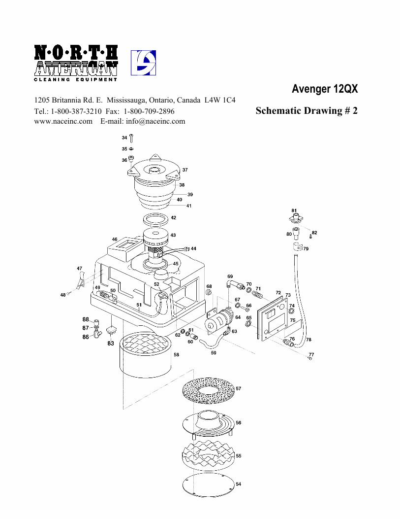
Tel.: 1-800-387-3210 Fax: 1-800-709-2896 Schematic Drawing # 2www.naceinc.com E-mail: [email protected]

Avenger 12QX1205 Britannia Rd. E. Mississauga, Ontario, Canada L4W 1C4Tel.: 1-800-387-3210 Fax: 1-800-709-2896 Parts List - Drawings 1 & 2www.naceinc.com E-mail: [email protected] Page 1 of 2
Item # Part # DESCRIPTION
1 SP-15178 COVERSP-15178C COVER WITH GASKET
2 SP-15179 GASKET3 SP-15188 FILTER4 SP-15131 ELBOW5 SP-15153 ELBOW6 SP-15551 SCREW TC+ 4x167 SP-15217 2 POSITION SWITCH
SP-15220 3 POSITION SWITCH8 SP-15119 PANEL LABEL9 SP-15177 CONTROL PANEL10 SP-15236 CONNECTING TERMINAL11 SP-15109 PLATE FOR FAIRLEAD12 SP-15190 BLUE UPPER TANK13 SP-15295 FAIRLEAD WITH NUT14 SP-15215 CABLE 3 x 14 AWG x 15m15 SP-15192 SOUNDPROOFING PANEL16 SP-15161 HOSE NIPPLE17 SP-15541 TIE18 SP-15544 SCREW 4,2 x 2219 SP-15160 CLIP20 SP-15161 HOSE NIPPLE21 SP-15159 CAP22 SP-15162 TIE23 SP-15358 DRAIN HOSE24 SP-15363 HOSE CUFF – D.3825 SP-125364 HOSE D.3826 SP-15334 HOSE CUFF – D.3827 SP-15193 SOUNDPROOFING PANEL28 SP-15514 NUT29 SP-15231 MICROSWITCH SUPPORT + 2 NUTS (SP-15514)
SP-15277 MICRO-SWITCH29A SP-15231C MICRO-SWITCH, COMPLETE WITH SUPPORT
AND 2 NUTS (SP-15277+ SP-15231)30 SP-15457 CONTROL LEVER31 SP-15599 PIN32 SP-155021 CIRCULAR CAP33 SP-155020 CAP34 SP-15560 SCREW – STAINLESS STEEL TC+ 5x3035 SP-15517I STAINLESS STEEL WASHER DIAM.5x1536 SP-157361 VIBRATION DAMPER37 SP-15194 ALUMINIUM SILENCER FLANGE38 SP-15195 SOUNDPROOFING FILTER39 SP-15196 SOUNDPROOFING FILTER40 SP-15197 SOUNDPROOFING FILTER41 SP-15198 SOUNDPROOFING FILTER42 SP-15825 MOTOR GASKET – 3mm43 SP-15809 3 STAGE MOTOR 1200W 120V 50/60Hz
Avenger 12QX1205 Britannia Rd. E. Mississauga, Ontario, Canada L4W 1C4Tel.: 1-800-387-3210 Fax: 1-800-709-2896 Parts List - Drawings 1 & 2www.naceinc.com E-mail: [email protected] Page 2 of 2
Item # Part # DESCRIPTION
44 SP-15234 CONNECTOR45 SP-15825 MOTOR GASKET – 3mm46 SP-15191 BLUE LOWER TANK47 SP-15142 COUPLER48 SP-15542 COUPLER SCREW49 SP-15608 FILTER50 SP-15747 BALLAST51 SP-15745 EXTRAFLEX PIPE52 SP-15724 CONNECTING PART
SP-15702B HOSE CUFF53 SP-15530 SCREW54 SP-15199 CIRCULAR LOWER PANEL55 SP-15200 LOWER SOUNDPROOFING DISC56 SP-15201 LOWER MOTOR FLANGE57 SP-15202 LOWER SOUNDPROOFING FILTER58 SP-15132 LOWER SOUNDPROOFING CILINDER59 SP-15746 RILSAN PIPE60 SP-15714 QUICK DISCONNECT - FEMALE61 SP-15540 METAL WASHER62 SP-15147 NEOPRENE WASHER63 SP-15622 ELBOW64 SP-15644 PUMP COMPLETE 100-120V 50-60 Hz 100 PSI65 SP-15564 RING NUT66 SP-15546 SCREW 5x25 (SHURFLO)67 SP-15517 WASHER68 SP-157360 VIBRATION DAMPING69 SP-15720 ELBOW
SP-15753 EXTENSION FOR METAL COUPLING70 SP-15137 O-RING71 SP-15687 METAL QUICK DISC. FEMALE72 SP-15186 PANEL GASKET73 SP-15148G PANEL74 SP-15163 BUSH75 SP-151190 LOWER PANEL LABEL76 SP-15262 CONNECTING PART77 SP-15536 SCREW78 SP-15291 CABLE SHEATH SP-15291C CABLE SHEATH WITH WIRES + SP-15260 + SP-1526579 SP-15265 TIE80 SP-15260 PLUG81 SP-15259 SOCKET82 SP-15538 SCREW TC+ 3.9x1383 SP-15279 RECTIFIER84 SP-15292 CIRCUIT BREAKER FOR BRUSH MOTOR (2 A)85 SP-15294 CAP FOR CIRCUIT BREAKER86 SP-15752 CONNECTING PART87 SP-15521 LOCK WASHER88 SP-15751 DRAIN VALVE

Ave
nger
12Q
X
Sc
hem
atic
Dra
win
g #
3
1205
Bri
tann
ia R
d. E
. M
issi
ssau
ga, O
ntar
io, C
anad
a L
4W 1
C4
Tel
.: 1-
800-
387-
3210
Fax
: 1-
800-
709-
2896
ww
w.n
acei
nc.c
om
E-m
ail:
info
@na
cein
c.co
m

Avenger 12QX1205 Britannia Rd. E. Mississauga, Ontario, Canada L4W 1C4Tel.: 1-800-387-3210 Fax: 1-800-709-2896 Parts List – Drawing 3www.naceinc.com E-mail: [email protected] Page 1 of 3
Item # Part # DESCRIPTION1 SP-15425 SLIDING BLOCK COVER2 SP-15538 SCREW TC+ 3,9x13 SCREW TC+ 3,9x133 SP-15567 SCREW TE 8x404 SP-15426N WHEEL5 SP-15568 NUT – DIAM.86 SP-154272 FRONT WHEELS SUPPORT7 SP-151151 FRONT WHEEL8 SP-15569 COTTER PIN9 SP-15428 SHAFT10 SP-15570 SCREW TC+ 5x1611 SP-15571 SCREW TC+ 5x4512 SP-15429 BELT COVER CARTER13 SP-15430 BELT14 SP-15572 SCREW TE 5x1615 SP-15431 PULLEY16 SP-15573 STOP DOWEL17 SP-15517 STAINLESS STEEL WASHER18 SP-15575 SCREW TE 5x1219 SP-15576 SCREW TE 10x1620 SP-15432 BEARING WITH SUPPORT21 SP-15433 BRUSH PULLEY22 SP-15434 SLIDING BLOCK23 SP-15455 BRUSH MOTOR 100-120V24 SP-15759C WATER PIPE25 SP-15766 NIPPLE 3/8”–1/8”26 SP-15757 MANIFOLD
SP-15757C MANIFOLD COMPLETE WITH NOZZLES & END FITTINGS27 SP-15758 CAP28 SP-15741 LOCKING NUT FOR NOZZLE29 SP-15617C REGULATION VALVE COMPLETE30 SP-15743 MESH SCREEN W/ CHECK VALVE31 SP-1570501 BRASS NOZZLE 0.1/11032 SP-15742 LOCKING NUT FOR NOZZLE33 SP-155650 MANIFOLD LOCK34 SP-15237 FAIRLEAD35 SP-15436 STEEL WIRE36 SP-15546 SCREW TC+ 5x25
SP-155172 WASHER DIAM. 5x20SP-15517 WASHER DIAM. 5x15SP-15461 SPRINGSP-155651 BUSH
37 SP-15605 ELBOW FOR 6/8 PIPE38 SP-15437 SHAFT FOR BRUSH39 SP-15438 PULLEY40 SP-15369 BRUSH41 SP-15517 WASHER 5x1542 SP-15577 WASHER 8x3243 SP-15578 SEEGER

Avenger 12QX1205 Britannia Rd. E. Mississauga, Ontario, Canada L4W 1C4Tel.: 1-800-387-3210 Fax: 1-800-709-2896 Parts List – Drawing 3www.naceinc.com E-mail: [email protected] Page 2 of 3
Item # Part # DESCRIPTION
44 SP-15580 WASHER 15,2x2745 SP-15461 SPRING46 SP-154391 SHAFT47 SP-15575 SCREW TE 5x1248 SP-15582 SCREW TE 6x849 SP-15422 WHEEL50 SP-15423 WHEEL COVER51 SP-154660 METAL HOUSING52 SP-154670 PEDAL53 SP-154671 RUBBER COVER FOR PEDAL54 SP-15585 SCREW TE 10x3555 SP-155401 WASHER 10x3056 SP-154712 SPRING57 SP-15526A LOCKING NUT D.1058 SP-155841 LOCK SCREW59 SP-155871 SPACER59A SP-15550 SCREW TC BRUGOLA 6x2060 SP-15576 SCREW TE 10x1661 SP-15549 SCREW TE 8x1662 SP-15456 KNOB63 SP-15588 ELASTIC PIN64 SP-154713 PRESSURE REGULATION KNOB65 SP-154716 ROD FOR KNOB66 SP-154711 SPRING FOR VACUUM PRESSURE67 SP-154680 CILINDER, COMPLETE WITH BRACKETS68 SP-154710 SPRING69 SP-154690 SUPPORT FOR VACUUM HEAD70 SP-15580 BRASS WASHER 15,2x27x171 SP-15569 COTTER PIN72 SP-15598 SCREW TE 10x5073 SP-15526B NUT D.10 H=874 SP-1547003 PAWL PIN75 SP-15607 PAWL SPRING76 SP-1547002 PAWL BODY77 SP-1547001 PAWL HAND GRIP
SP-154700C COMPLETE PAWL78 SP-15580 WASHER 15,2 x 2779 SP-154714 SUPPORT FOR VACUUM HEAD80 SP-15549 SCREW TE 8x1681 SP-15585 SCREW TE 10x3582 SP-15471 SUPPORT FOR VAC.HEAD ORIENTATION83 SP-15449C VACUUM HEAD WITH HOSE D.38 AND SUPPORT
(ITEMS 79,80,81,82,83)84 SP-154181 SHAFT FOR WHEELS

Avenger 12QX1205 Britannia Rd. E. Mississauga, Ontario, Canada L4W 1C4Tel.: 1-800-387-3210 Fax: 1-800-709-2896 Parts List – Drawing 3www.naceinc.com E-mail: [email protected] Page 3 of 3
Item # Part # DESCRIPTION
85 SP-1557820 SEEGER DIAM. 2086 SP-15583 SCREW TE 8x2087 SP-15421 LOWER BEARING FLANGE88 SP-15419 PILLOW BLOCK89 SP-15420 UPPER BEARING FLANGE90 SP-154270 DISTANCE PLATE FOR WHEELS91 SP-15334 HOSE COUPLING92 SP-15370 VACUUM HOSE93 SP-15709 METAL QUICK DISC. MALE + SPRING94 SP-155670 SCREW95 SP-15568 DIE96 SP-15 5080 STOP PLATE97 SP-155091 SCREW98 SP-155081 ROPE LOCK