Embed Size (px)
Citation preview
350Z
D748_746_744_Quick_V1.1
Installation Guide
Intelligent Video Surveillance GUI Display with USB Mouse Control
Please read instructions thoroughly before operation and retain it for future reference.
For the actual display & operation, please refer to your DVR in hand.
IMPORTANT SAFEGUARD
CAUTION
RISK OF ELECTRIC SHOCK
CAUTION: To reduce the risk of electric shock, do not expose this apparatus to rain or moisture. Only operate this apparatus from the type of power source indicated on the label. The company shall not be liable for any damages arising out of any improper use, even if we have been advised of the possibility of such damages.
The lightning flash with arrowhead symbol, within an equilateral triangle, is intended to alert the user to the presence of uninsulated “dangerous voltage” within the product’s enclosure that may be of sufficient magnitude to constitute a risk of electric shock to persons.
This exclamation point within an equilateral triangle is intended to alert the user to the presence of important operating and maintenance (servicing) instructions in the literature accompanying the appliance.
All lead-free products offered by the company comply with the requirements of the European law on the Restriction of Hazardous Substances (RoHS) directive, which means our manufacture processes and products are strictly “lead-free” and without the hazardous substances cited in the directive.
The crossed-out wheeled bin mark symbolizes that within the European Union the product must be collected separately at the product end-of-life. This applies to your product and any peripherals marked with this symbol. Do not dispose of these products as unsorted municipal waste. Contact your local dealer for procedures for recycling this equipment.
This apparatus is manufactured to comply with the radio interference requirements.
Trademark Acknowledgements
and (EagleEyes) - The trademark application is filed and under process in the U.S. and other countries.
iPhone® is the registered trademark of Apple Inc., and Apple holds the intelligential property rights to the iPhone content.
Disclaimer The information in this manual was current when released. We reserve the right to revise or remove any content in this manual at any time. We do not warrant or assume any legal liability or responsibility for the accuracy, completeness, or usefulness of this manual. For the actual display & operation, please refer to your DVR in hand. The content of this manual is subject to change without notice.
Grounding This is a Safety Class 1 Product (provided with a protective earthing ground incorporated in the power cord). The mains plug shall only be inserted in a socket outlet provided with a protective earth contact. Any interruption of the protective conductor inside or outside of the instrument is likely to make the instrument dangerous. Intentional interruption is prohibited.
Water & Moisture Do not expose this product to dripping or splashing and that no objects filled with liquids, such as vases, shall be placed on the product.
MPEG4 Licensing THIS PRODUCT IS LICENSED UNDER THE MPEG-4 VISUAL PATENT PORTFOLIO LICENSE FOR THE PERSONAL AND NON-COMMERCIAL USE OF A CONSUMER FOR (i) ENCODING VIDEO IN COMPLIANCE WITH THE MPEG-4 VISUAL STANDARD (“MPEG-4 VIDEO”) AND/OR (ii) DECODING MPEG-4 VIDEO THAT WAS ENCODED BY A CONSUMER ENGAGED IN A PERSONAL AND NON-COMMERCIAL ACTIVITY AND/OR WAS OBTAINED FROM A VIDEO PROVIDER LICENSED BY MPEG LA TO PROVIDE MPEG-4 VIDEO. NO LICENSE IS GRANTED OR SHALL BE IMPLIED FOR ANY OTHER USE. ADDITIONAL INFORMATION INCLUDING THAT RELATING TO PROMOTIONAL INTERNAL AND COMMERCIAL USES AND LICENSING MAY BE OBTAINED FROM MPEG LA, LLC. SEE HTTP://WWW.MPEGLA.COM.
GPL Licensing
This product contains codes which are developed by Third-Party-Companies and which are subject to the GNU General Public License (“GPL”) or the GNU Lesser Public License (“LGPL”). The GPL Code used in this product is released without warranty and is subject to the copyright of the corresponding author. Further source codes which are subject to the GPL-licenses are available upon request. We are pleased to provide our modifications to the Linux Kernel, as well as a few new commands, and some tools to get you into the code. The codes are provided on the FTP site, and please download them from the following site or you can refer to your distributor: ftp://ftp.dvrtw.com.tw/GPL/AV074/
TABLE OF CONTENTS
1. PRODUCT OVERVIEW............................................................................................................ 1
2. CONNECTION AND SETUP .................................................................................................... 2
2.1 Prerequisites....................................................................................................................................................2 2.2 SATA HDD Installation .....................................................................................................................................2 2.3 Installing DCCS Camera..................................................................................................................................3 2.4 Connecting DCCS Camera..............................................................................................................................3 2.5 DVR Power On ................................................................................................................................................4 2.6 Date and Time Setting .....................................................................................................................................4 2.7 Clear Hard Disk ...............................................................................................................................................4 2.8 Password Setting.............................................................................................................................................5 2.9 Examining Signal Transmission .......................................................................................................................5 2.10 Configuring DCCS Camera............................................................................................................................6
2.10.1 For a PTZ camera................................................................................................................................6 2.10.2 For a zoom lens control camera ..........................................................................................................6
3. GUI DISPLAY WITH USB MOUSE CONTROL........................................................................ 7
3.1 Connect USB Mouse .......................................................................................................................................7 3.2 Quick Menu Bar ...............................................................................................................................................7 3.3 Main Menu.......................................................................................................................................................8
Main Menu Structure ......................................................................................................................................8
4. FRONT AND REAR PANELS ................................................................................................ 10
4.1 Front Panel ....................................................................................................................................................10 4.2 Rear Panel.....................................................................................................................................................11
5. BASIC OPERATION............................................................................................................... 12
5.1 Live Page.......................................................................................................................................................12 5.2 Record Icon ...................................................................................................................................................12 5.3 Playback ........................................................................................................................................................12
Playback Control ..........................................................................................................................................13 Event Search ................................................................................................................................................13 Audio Playback.............................................................................................................................................13
5.4 User Level Switch ..........................................................................................................................................13 5.5 Video Output Switch ......................................................................................................................................14
APPENDIX 1. SET IPHONE PUSH NOTIFICATION.................................................................. 15
A1.1 Prerequisite .................................................................................................................................................15 A1.2 Set iPhone...................................................................................................................................................15
A1.2.1 Program Download............................................................................................................................15 A1.2.2 Program Setup ..................................................................................................................................16 A1.2.3 Push Notification On..........................................................................................................................17
APPENDIX 2. SET FLOW COUNTING / VIRTUAL FENCE / ONE-WAY PASS........................ 18
A2.1 IVS APPLICATION ......................................................................................................................................19 A2.1.1 FLOW COUNTING............................................................................................................................19 A2.1.2 VIRTUAL FENCE and ONE WAY PASS............................................................................................20
A2.2 IVS STATISTICS .........................................................................................................................................21
1
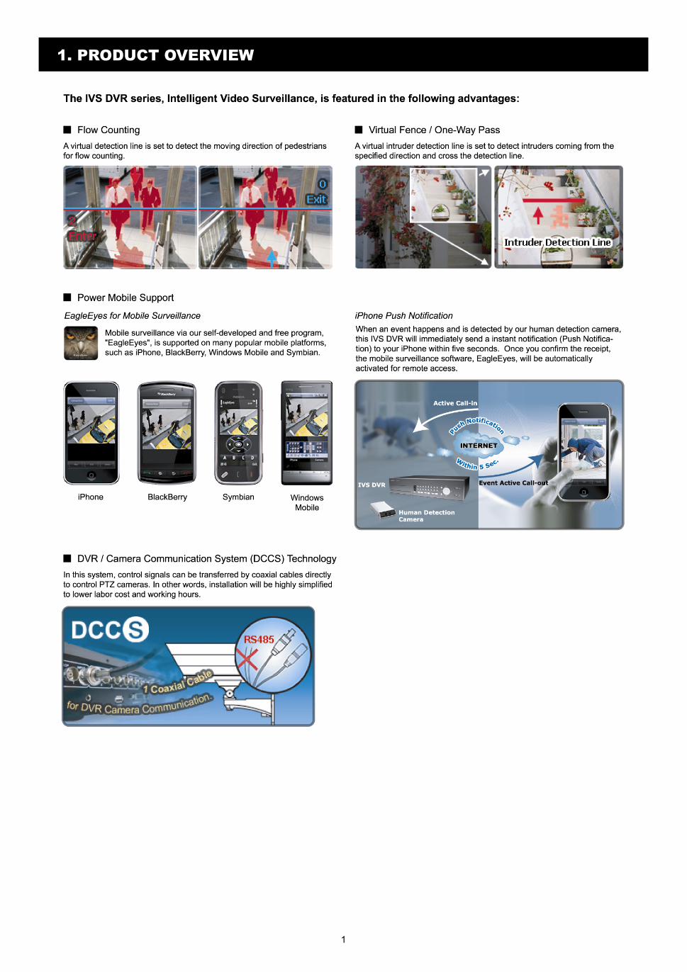
1. PRODUCT OVERVIEW
2
2. CONNECTION AND SETUP
Before the DVR is powered on, make sure you have installed a hard disk, connected at least one camera and a monitor. For details, please refer to the following sections.
Note: The DVR is designed to automatically detect the video system of the connected cameras (NTSC or PAL). To make sure the system detection is correct, please check if the cameras are connected to the DVR and power-supplied before the DVR is powered on.
Note: The connection and setup described below are for DCCS devices only. For details about connecting cameras other than DCCS ones, please refer to the DVR user manual.
2.1 Prerequisites
Make sure your cameras support the DCCS function. For details, please check with your distributor or installer.
To ensure the signal transmission, the recommended distance between this DVR and cameras should not exceed 200 meters by using 3C2V coaxial cables (112 braids).
However, different materials used in 3C2V coaxial cables with different connection distance may cause some effects for the availability and fluency of signal transmission.
Therefore, please do the DCCS test as instructed in “2.9 Examining Signal Transmission” at page 5 when the connection is completed to ensure this system can work normally.
It’s not allowed to use a signal booster or modem to amplify signals and extend the connection distance.
The DCCS function doesn’t support the channel which is looped from a DCCS camera connected to the same DCCS DVR or to other DCCS DVR.
2.2 SATA HDD Installation
A SATA HDD must be installed before the DVR is powered on.
Note: It’s recommended to clear all data in the hard disk when the DVR is powered on and the date & time are set correctly to ensure the recorded data are not mixed with other data previously saved in the same hard disk. For details, please refer to “2.7 Clear Hard Disk” at page 4.
For 16CH & 8CH Models
Step1: Loose the screws on the upper cover and open the upper cover of the DVR.
Note: The DVR cover is made of metal. Please be careful with its edge when you remove the cover.
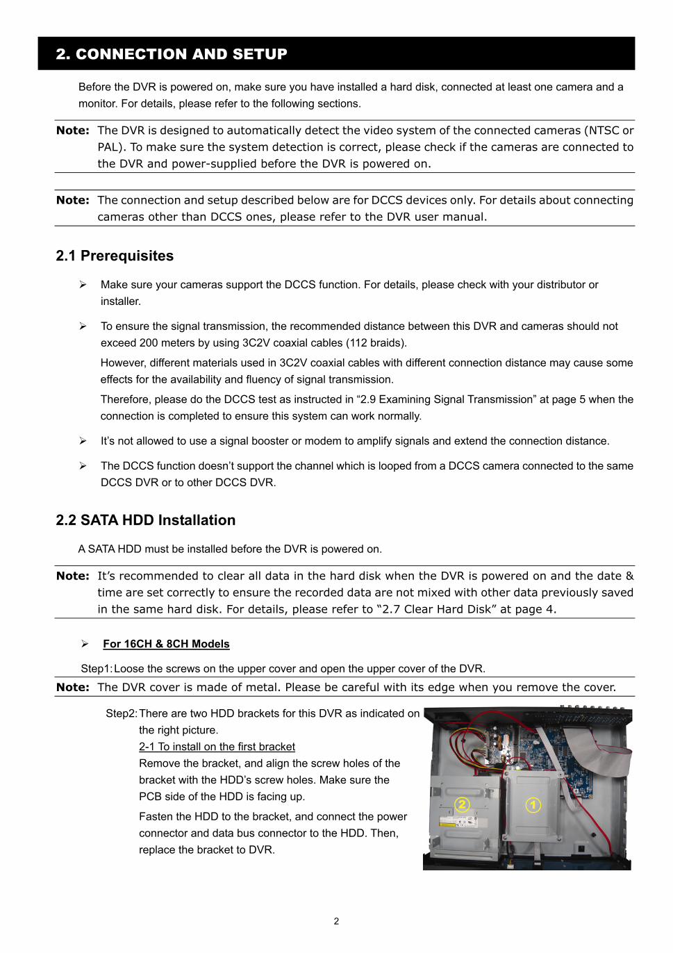
Step2: There are two HDD brackets for this DVR as indicated on the right picture. 2-1 To install on the first bracket Remove the bracket, and align the screw holes of the bracket with the HDD’s screw holes. Make sure the PCB side of the HDD is facing up.
Fasten the HDD to the bracket, and connect the power connector and data bus connector to the HDD. Then, replace the bracket to DVR.
3
2-2 To install on the second bracket Connect the power connector and data bus connector to the HDD.
When connecting the power cable, make sure the cable is passed through the power cable of DVD writer. This is to prevent the HDD power cable from interfering with the fan spinning.
Align the screw holes of the bracket with the HDD’s screw holes. Make sure the PCB side of the HDD is facing up. Then, fasten the HDD to the bracket.
Step3: Close the upper cover of the DVR, and fasten all the screws you loosened in Step1.
For 4CH Model
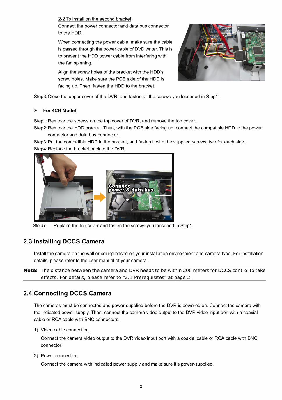
Step1: Remove the screws on the top cover of DVR, and remove the top cover. Step2: Remove the HDD bracket. Then, with the PCB side facing up, connect the compatible HDD to the power
connector and data bus connector. Step3: Put the compatible HDD in the bracket, and fasten it with the supplied screws, two for each side. Step4: Replace the bracket back to the DVR.
Step5: Replace the top cover and fasten the screws you loosened in Step1.
2.3 Installing DCCS Camera
Install the camera on the wall or ceiling based on your installation environment and camera type. For installation details, please refer to the user manual of your camera.
Note: The distance between the camera and DVR needs to be within 200 meters for DCCS control to take effects. For details, please refer to “2.1 Prerequisites” at page 2.
2.4 Connecting DCCS Camera
The cameras must be connected and power-supplied before the DVR is powered on. Connect the camera with the indicated power supply. Then, connect the camera video output to the DVR video input port with a coaxial cable or RCA cable with BNC connectors.
1) Video cable connection
Connect the camera video output to the DVR video input port with a coaxial cable or RCA cable with BNC connector.
2) Power connection
Connect the camera with indicated power supply and make sure it’s power-supplied.
4
2.5 DVR Power On
This device should be operated only with the type of power source indicated on the manufacturer’s label. Connect the indicated AC power cord to the power adapter, and plug into an electrical outlet. The power LED will be on.
Note: Before the DVR is powered on, make sure (1) the cameras are connected and power-supplied for the detection of the camera video system to be correct, and (2) a monitor (either LCD or CRT monitor) is connected to the DVR for correct video output detection.
Note: To ensure that your DVR works constantly and properly, it's recommended to use an UPS,
Uninterruptible Power Supply (Optional), for continuously operation.
2.6 Date and Time Setting
Before operating your DVR, please set the date and time on your DVR FIRST.
Note: Please DO NOT change the date or time of your DVR after the recording function is activated. Otherwise, the recorded data will be disordered and you will not be able to find the recorded file to backup by time search. If users change the date or time accidentally when the recording function is activated, it’s recommended to clear all HDD data, and start recording again.
Note: For the first time to use the DVR, please power it on for at least 48 hours continuously after the date & time is set correctly. It helps to prevent DVR time from resetting after the disconnecting of DVR power. If the DVR time resets after the disconnecting of DVR power, for example, caused by a power outage, the battery might run out and please replace the battery as described in “APPENDIX 6” in the DVR user manual.
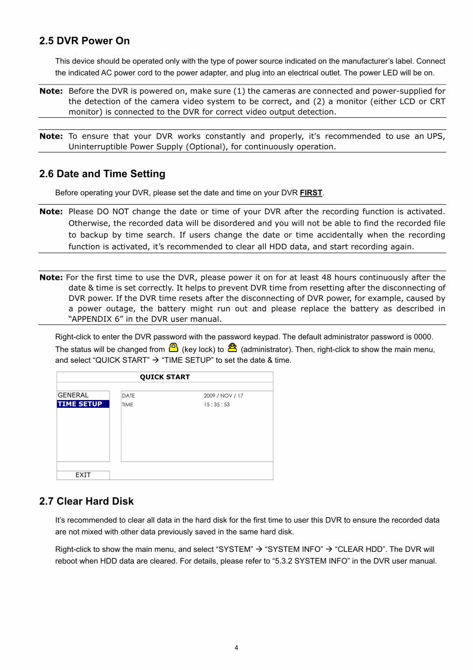
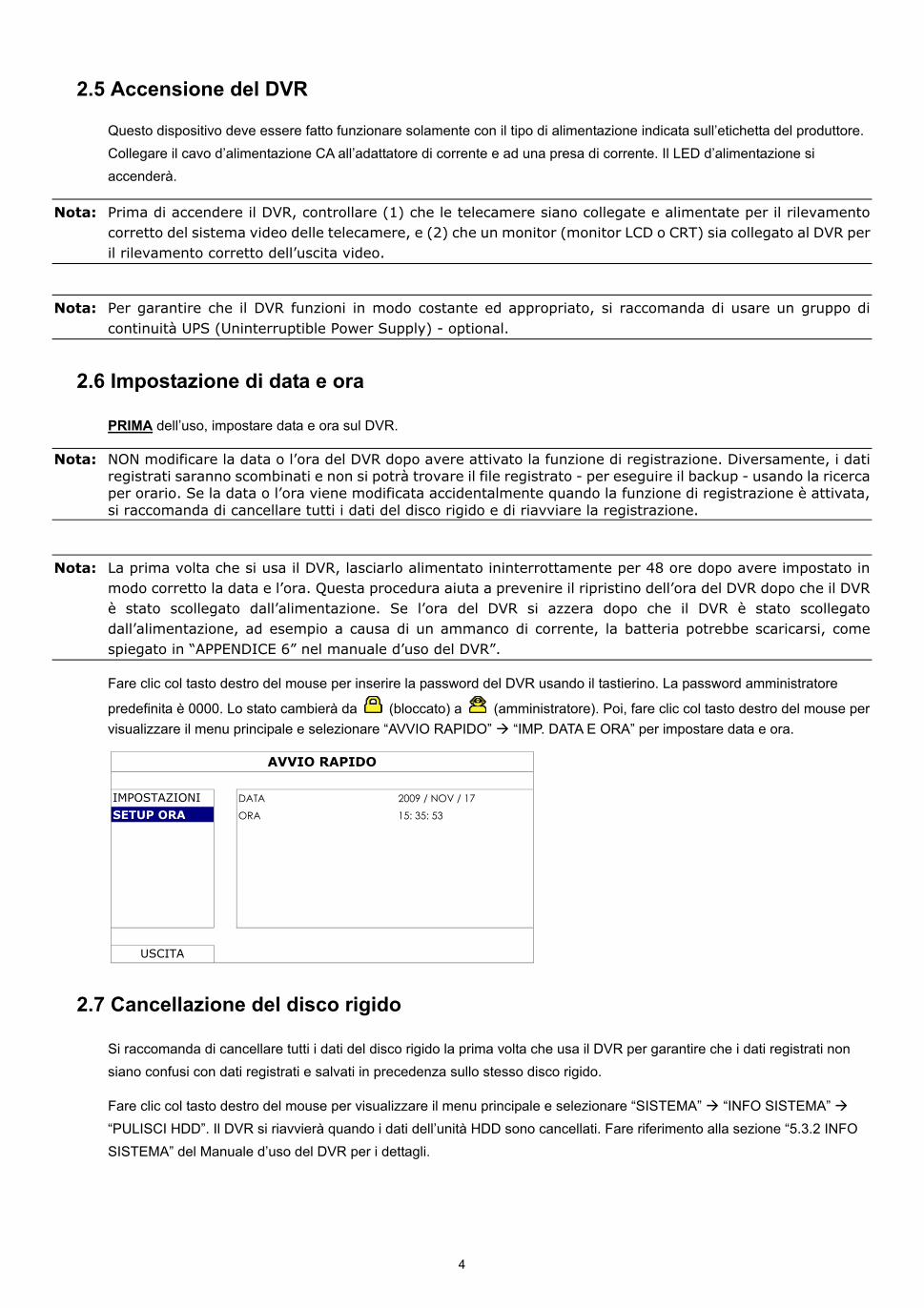
Right-click to enter the DVR password with the password keypad. The default administrator password is 0000. The status will be changed from (key lock) to (administrator). Then, right-click to show the main menu, and select “QUICK START” “TIME SETUP” to set the date & time.
QUICK START
GENERAL DATE 2009 / NOV / 17 TIME SETUP TIME 15 : 35 : 53
EXIT
2.7 Clear Hard Disk It’s recommended to clear all data in the hard disk for the first time to user this DVR to ensure the recorded data are not mixed with other data previously saved in the same hard disk.
Right-click to show the main menu, and select “SYSTEM” “SYSTEM INFO” “CLEAR HDD”. The DVR will reboot when HDD data are cleared. For details, please refer to “5.3.2 SYSTEM INFO” in the DVR user manual.
5
SYSTEM
TOOLS BAUD RATE 2400 SYSTEM INFO HOST ID 000 USB BACKUP R.E.T.R 5 DVD BACKUP AUTO KEY LOCK NEVER CLEAR HDD HDD-0 RESET DEFAULT SUBMIT REMOTE CONTROL ID 000 SERIAL TYPE RS485 VIDEO FORMAT NTSC VERSION 1019-1008-1010-1010
EXIT
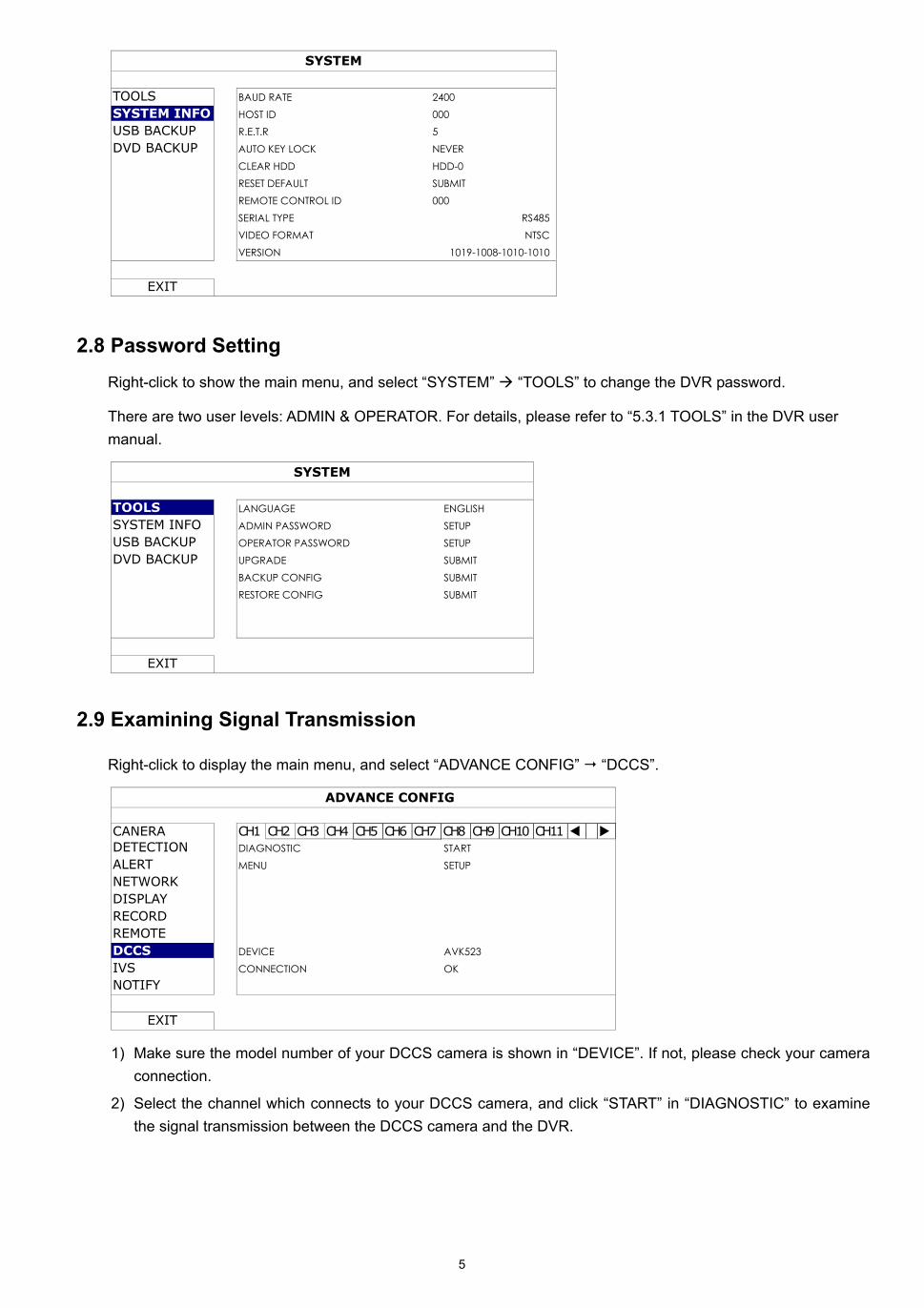
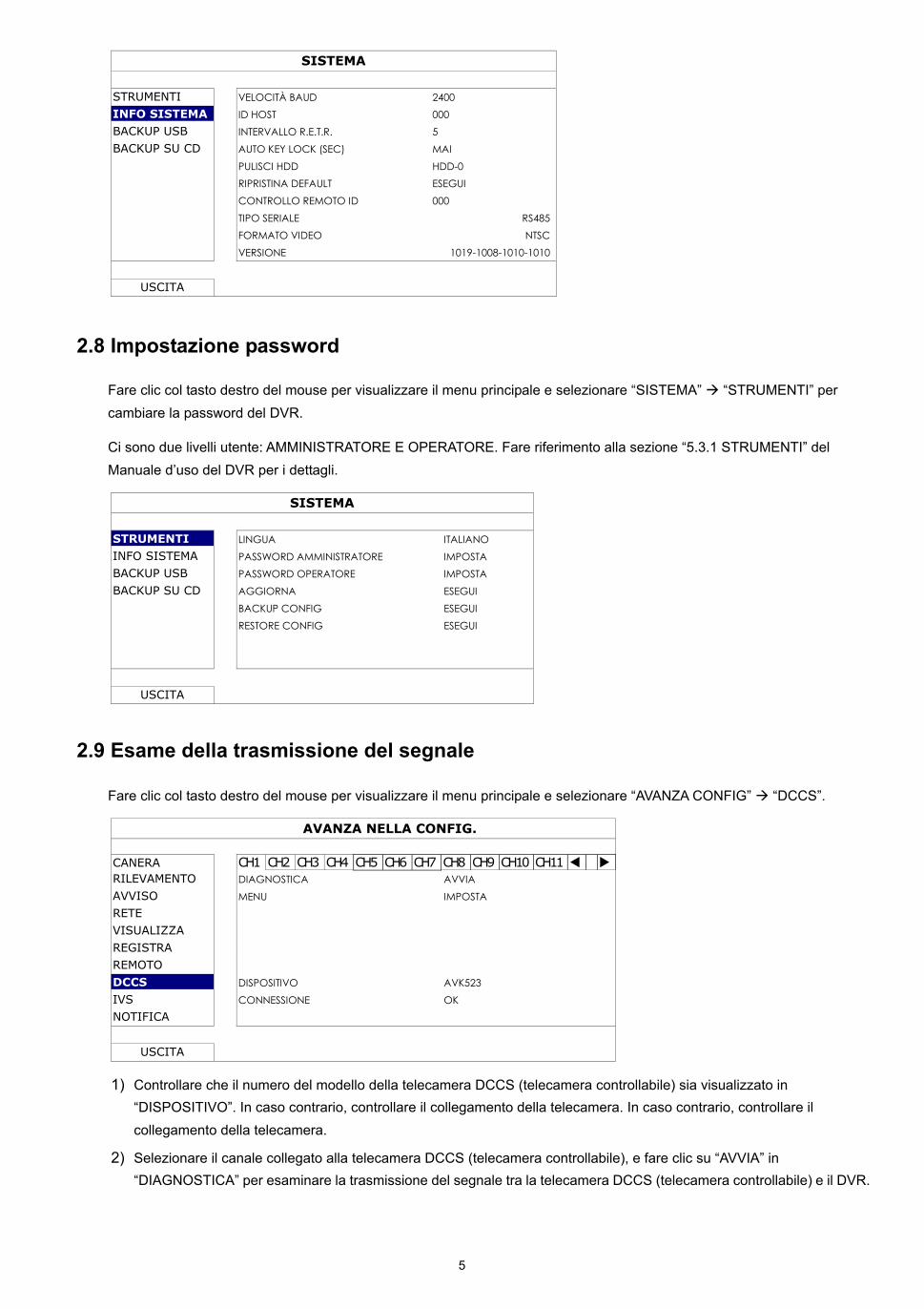
2.8 Password Setting Right-click to show the main menu, and select “SYSTEM” “TOOLS” to change the DVR password.
There are two user levels: ADMIN & OPERATOR. For details, please refer to “5.3.1 TOOLS” in the DVR user manual.
SYSTEM
TOOLS LANGUAGE ENGLISH SYSTEM INFO ADMIN PASSWORD SETUP USB BACKUP OPERATOR PASSWORD SETUP DVD BACKUP UPGRADE SUBMIT BACKUP CONFIG SUBMIT RESTORE CONFIG SUBMIT
EXIT
2.9 Examining Signal Transmission
Right-click to display the main menu, and select “ADVANCE CONFIG” “DCCS”.
ADVANCE CONFIG
CANERA CH1 CH2 CH3 CH4 CH5 CH6 CH7 CH8 CH9 CH10 CH11 DETECTION DIAGNOSTIC START ALERT MENU SETUP NETWORK DISPLAY RECORD REMOTE DCCS DEVICE AVK523 IVS CONNECTION OK NOTIFY
EXIT
1) Make sure the model number of your DCCS camera is shown in “DEVICE”. If not, please check your camera connection.
2) Select the channel which connects to your DCCS camera, and click “START” in “DIAGNOSTIC” to examine the signal transmission between the DCCS camera and the DVR.
6
3) In “CONNECTION”, it shows the examining result for DCCS signal transmission between the DVR and camera. The message is as follows:
MESSAGE SHOWN MEANING
CHECKING The DVR is checking the DCCS signal transmission between the DVR and camera.
OK The signal transmission is fine and the DCCS function works properly.
FAIL The signal transmission is too weak or not available for the DCCS function to work properly.
2.10 Configuring DCCS Camera
DCCS cameras have three types: PTZ cameras, zoom lens control cameras, and human detection cameras. Based on the camera type, different camera settings are needed as described below.
Note: iPhone Push Notification is available only when a human detection camera is connected properly to the correct channel which supports DCCS. For iPhone Push Notification to work properly, please refer to “APPENDIX 1. SET IPHONE PUSH NOTIFICATION” at page 15.
2.10.1 For a PTZ camera
Switch to the channel which connects to your PTZ camera, and click “ ” on the quick menu bar to
display the PTZ control panel.
Configure the camera by clicking “ ”. For camera configuration details, please refer to its user manual.
2.10.2 For a zoom lens control camera
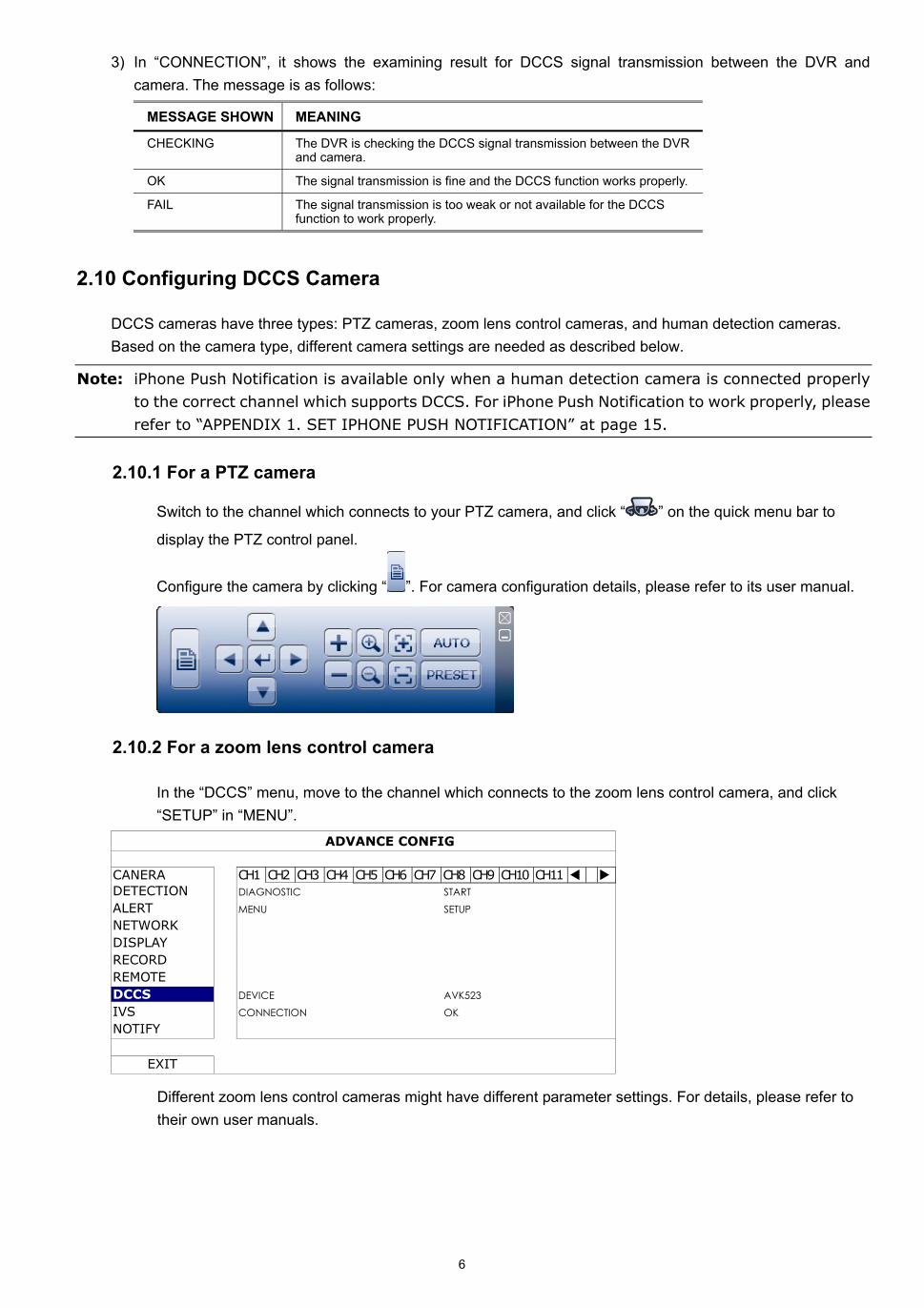
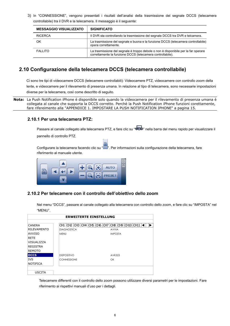
In the “DCCS” menu, move to the channel which connects to the zoom lens control camera, and click “SETUP” in “MENU”.
ADVANCE CONFIG
CANERA CH1 CH2 CH3 CH4 CH5 CH6 CH7 CH8 CH9 CH10 CH11 DETECTION DIAGNOSTIC START ALERT MENU SETUP NETWORK DISPLAY RECORD REMOTE DCCS DEVICE AVK523 IVS CONNECTION OK NOTIFY
EXIT
Different zoom lens control cameras might have different parameter settings. For details, please refer to their own user manuals.
7
3. GUI DISPLAY WITH USB MOUSE CONTROL
3.1 Connect USB Mouse
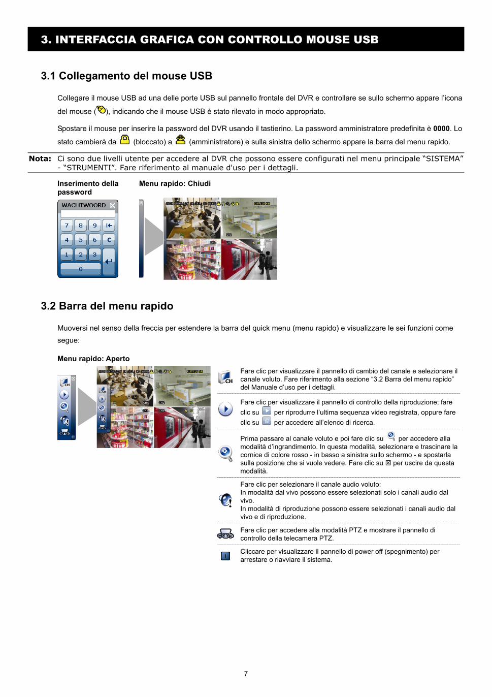
Connect your USB mouse to one of the USB ports on the DVR front panel, and check if there’s a mouse icon ( ) on the screen, indicating the USB mouse is detected properly.
Move your mouse to enter the DVR password with the password keypad. The default administrator password is 0000. The status will be changed from (key lock) to (administrator), and the quick menu bar appears on the left side of the screen.
Note: There are two user levels for DVR access which can be set in the main menu “SYSTEM” “TOOLS”.
For details, please refer to your user manual.
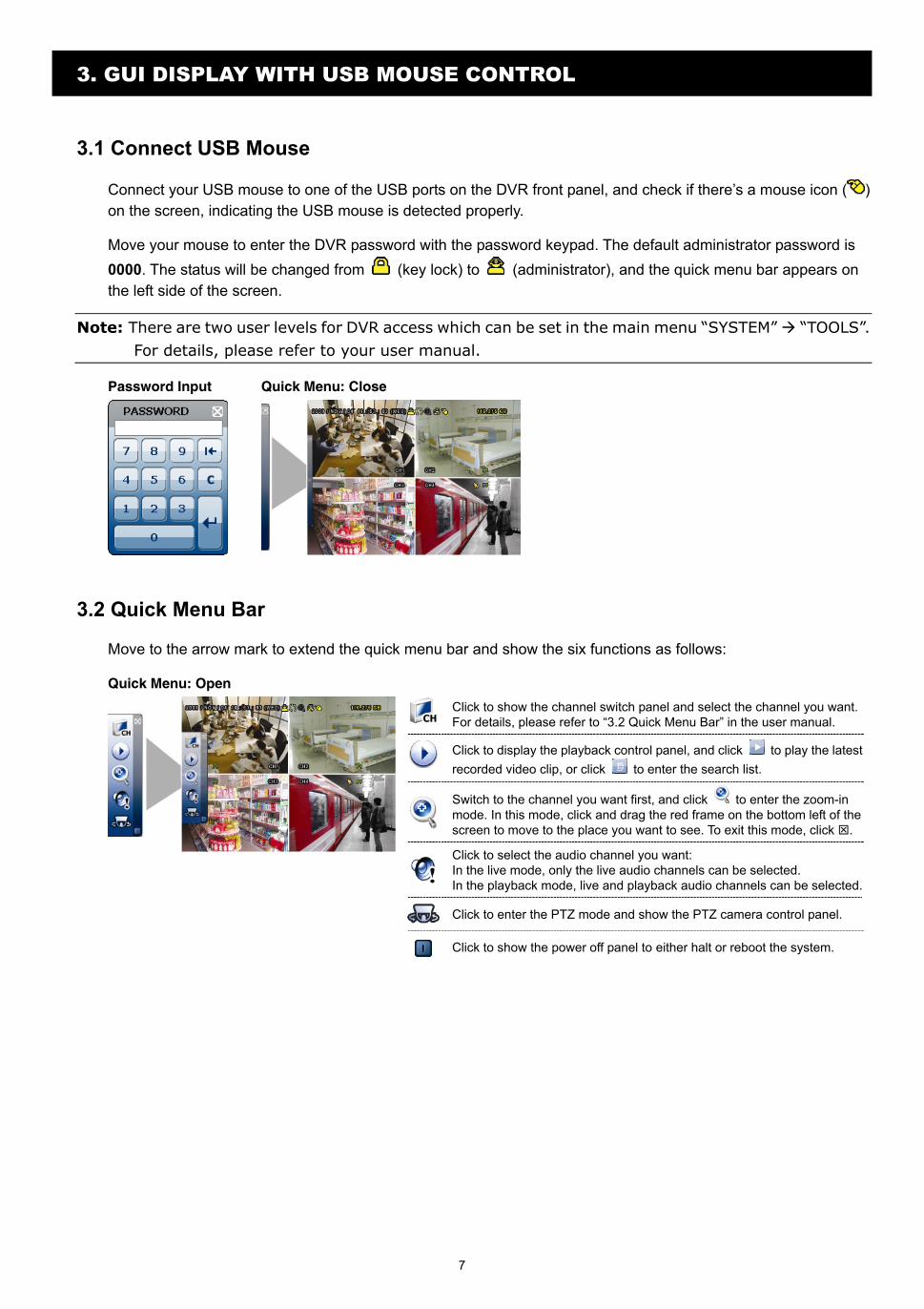
Password Input Quick Menu: Close
3.2 Quick Menu Bar
Move to the arrow mark to extend the quick menu bar and show the six functions as follows:
Quick Menu: Open
Click to show the channel switch panel and select the channel you want. For details, please refer to “3.2 Quick Menu Bar” in the user manual.
Click to display the playback control panel, and click to play the latest recorded video clip, or click to enter the search list.
Switch to the channel you want first, and click to enter the zoom-in mode. In this mode, click and drag the red frame on the bottom left of the screen to move to the place you want to see. To exit this mode, click .
Click to select the audio channel you want: In the live mode, only the live audio channels can be selected. In the playback mode, live and playback audio channels can be selected.
Click to enter the PTZ mode and show the PTZ camera control panel.
Click to show the power off panel to either halt or reboot the system.
8
3.3 Main Menu
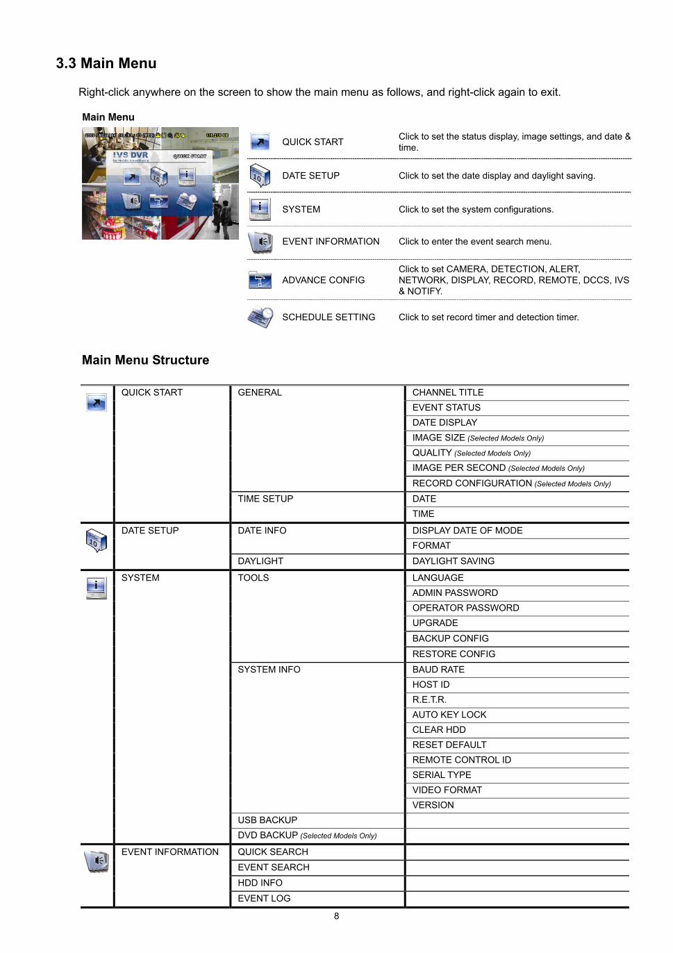
Right-click anywhere on the screen to show the main menu as follows, and right-click again to exit.
Main Menu
QUICK START Click to set the status display, image settings, and date & time.
DATE SETUP Click to set the date display and daylight saving.
SYSTEM Click to set the system configurations.
EVENT INFORMATION Click to enter the event search menu.
ADVANCE CONFIG Click to set CAMERA, DETECTION, ALERT, NETWORK, DISPLAY, RECORD, REMOTE, DCCS, IVS & NOTIFY.
SCHEDULE SETTING Click to set record timer and detection timer.
Main Menu Structure
QUICK START GENERAL CHANNEL TITLE EVENT STATUS DATE DISPLAY IMAGE SIZE (Selected Models Only) QUALITY (Selected Models Only) IMAGE PER SECOND (Selected Models Only)
RECORD CONFIGURATION (Selected Models Only)
TIME SETUP DATE
TIME
DATE SETUP DATE INFO DISPLAY DATE OF MODE FORMAT DAYLIGHT DAYLIGHT SAVING
SYSTEM TOOLS LANGUAGE ADMIN PASSWORD OPERATOR PASSWORD UPGRADE
BACKUP CONFIG
RESTORE CONFIG
SYSTEM INFO BAUD RATE HOST ID R.E.T.R. AUTO KEY LOCK CLEAR HDD RESET DEFAULT REMOTE CONTROL ID SERIAL TYPE VIDEO FORMAT VERSION USB BACKUP
DVD BACKUP (Selected Models Only)
EVENT INFORMATION QUICK SEARCH
EVENT SEARCH
HDD INFO
EVENT LOG
9
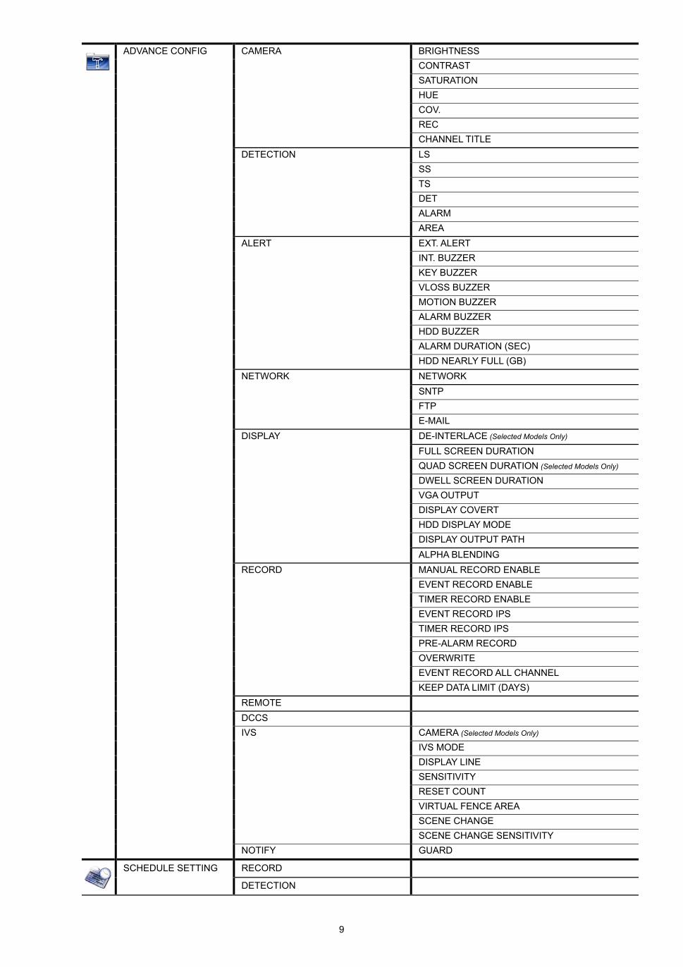
ADVANCE CONFIG CAMERA BRIGHTNESS CONTRAST SATURATION HUE COV. REC CHANNEL TITLE DETECTION LS SS TS DET ALARM AREA ALERT EXT. ALERT INT. BUZZER KEY BUZZER VLOSS BUZZER MOTION BUZZER ALARM BUZZER HDD BUZZER ALARM DURATION (SEC) HDD NEARLY FULL (GB) NETWORK NETWORK SNTP FTP E-MAIL DISPLAY DE-INTERLACE (Selected Models Only) FULL SCREEN DURATION QUAD SCREEN DURATION (Selected Models Only) DWELL SCREEN DURATION VGA OUTPUT DISPLAY COVERT HDD DISPLAY MODE DISPLAY OUTPUT PATH ALPHA BLENDING RECORD MANUAL RECORD ENABLE EVENT RECORD ENABLE TIMER RECORD ENABLE EVENT RECORD IPS TIMER RECORD IPS PRE-ALARM RECORD OVERWRITE EVENT RECORD ALL CHANNEL KEEP DATA LIMIT (DAYS) REMOTE DCCS IVS CAMERA (Selected Models Only) IVS MODE DISPLAY LINE SENSITIVITY RESET COUNT VIRTUAL FENCE AREA SCENE CHANGE SCENE CHANGE SENSITIVITY
NOTIFY GUARD
SCHEDULE SETTING RECORD
DETECTION
10
4. FRONT AND REAR PANELS
4.1 Front Panel
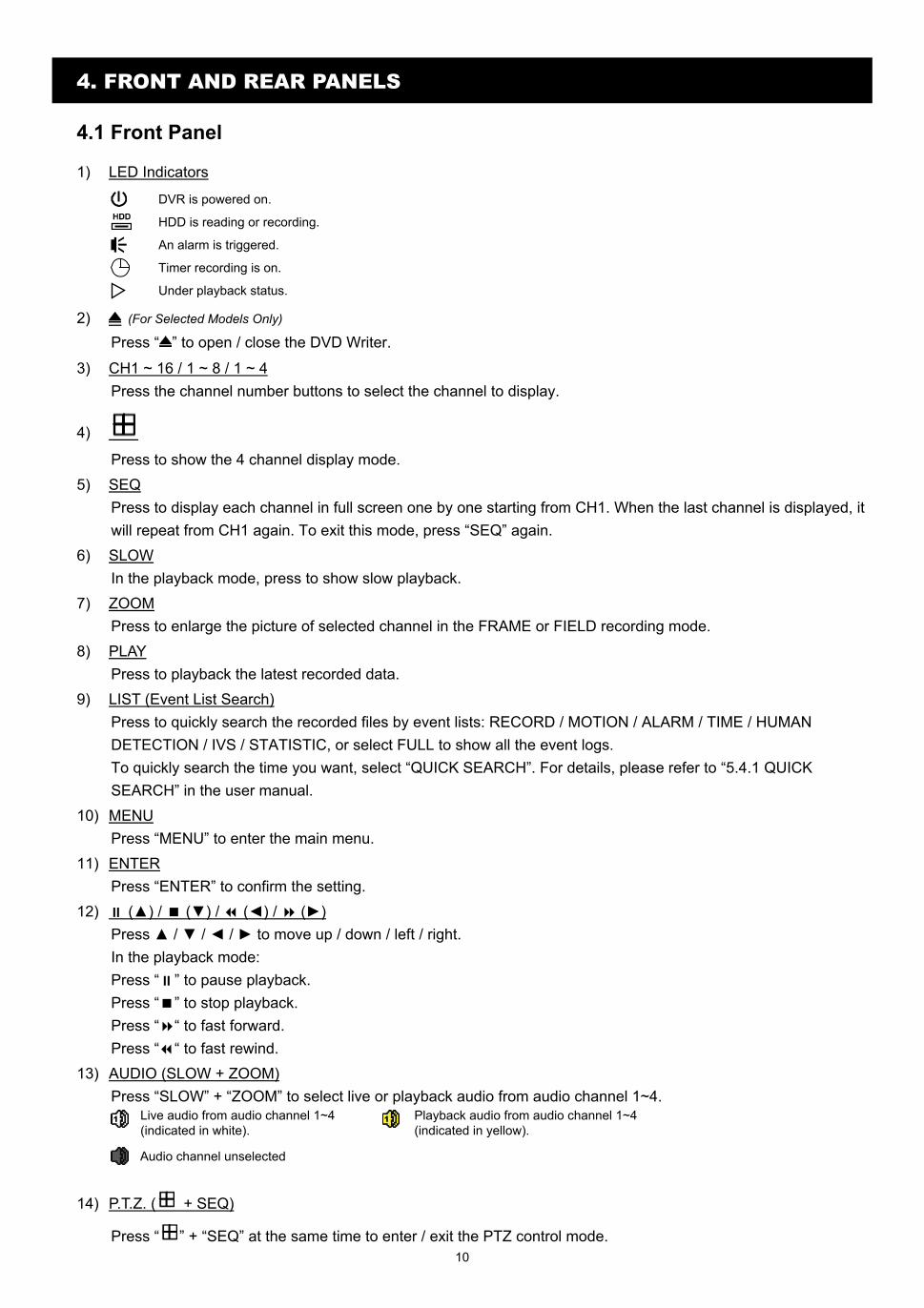
1) LED Indicators
DVR is powered on.
HDD is reading or recording.
An alarm is triggered.
Timer recording is on.
Under playback status.
2) (For Selected Models Only) Press “ ” to open / close the DVD Writer.
3) CH1 ~ 16 / 1 ~ 8 / 1 ~ 4 Press the channel number buttons to select the channel to display.
4)
Press to show the 4 channel display mode. 5) SEQ
Press to display each channel in full screen one by one starting from CH1. When the last channel is displayed, it will repeat from CH1 again. To exit this mode, press “SEQ” again.
6) SLOW In the playback mode, press to show slow playback.
7) ZOOM Press to enlarge the picture of selected channel in the FRAME or FIELD recording mode.
8) PLAY Press to playback the latest recorded data.
9) LIST (Event List Search) Press to quickly search the recorded files by event lists: RECORD / MOTION / ALARM / TIME / HUMAN DETECTION / IVS / STATISTIC, or select FULL to show all the event logs. To quickly search the time you want, select “QUICK SEARCH”. For details, please refer to “5.4.1 QUICK SEARCH” in the user manual.
10) MENU Press “MENU” to enter the main menu.
11) ENTER Press “ENTER” to confirm the setting.
12) () / () / () / () Press / / / to move up / down / left / right. In the playback mode: Press “ ” to pause playback. Press “ ” to stop playback. Press “ “ to fast forward. Press “ “ to fast rewind.
13) AUDIO (SLOW + ZOOM) Press “SLOW” + “ZOOM” to select live or playback audio from audio channel 1~4.
Live audio from audio channel 1~4 (indicated in white).
Playback audio from audio channel 1~4 (indicated in yellow).
Audio channel unselected
14) P.T.Z. ( + SEQ)
Press “ ” + “SEQ” at the same time to enter / exit the PTZ control mode.
11
15) USB port There are two USB ports on the front panel, one for connecting your USB mouse for mouse control, and the other one for connecting your USB flash drive for video backup.
Note: It’s not allowed to have two USB mice or two USB flash drives connected on the front panel.
Note: For the compatible USB flash drive list, please refer to “APPENDIX 3” in the user manual.
4.2 Rear Panel
1) 75Ω / HI-IMPEDANCE (For Selected Models Only) When using Loop function, please switch to HI-IMPEDANCE. When you don’t use Loop function, please switch to 75Ω.
2) VIDEO IN (1 ~ 16 / 1 ~ 8 / 1 ~ 4): Connect to the video connector of a camera. VIDEO LOOP (1 ~ 16 / 1 ~ 8): Video output connector.
Note: The DVR will automatically detect the video system of the camera, please make sure that the cameras are properly connected to the DVR and power-supplied before the DVR is turned on.
3) AUDIO IN (1~4) Connect to the audio connector of a camera if the camera supports audio recording.
Note: To make a video backup with audio, make sure the camera which supports the audio function is connected to the video-in channel and audio-in channel. For example, the audio data from audio CH1 will be recorded with the video data from video CH1.
4) AUDIO OUT Connect to a speaker with 1 mono audio output.
Note: To know how many audio outputs your DVR supports, please refer to its specifications.
5) MONITOR Connect to a CRT monitor for video output.
Note: When both MONITOR and VGA are connected, press the left key on the DVR front panel during DVR power-on to force the video output via MONITOR. For details, please refer to “5.5 Video Output Switch”.
6) CALL (For Selected Models Only) Connect to a monitor specific for sequence display.
7) VGA Connect to a LCD monitor directly.
Note: When both MONITOR and VGA are connected, press the right key on the DVR front panel during DVR power-on to force the video output via VGA. For details, please refer to “5.5 Video Output Switch”.
8) IR (For Selected Models Only) Connect the IR receiver extension line for remote control.
9) EXTERNAL I/O This port is used to connect external devices (such as speed dome cameras or external alarm, etc).
10) LAN Connect to Internet by LAN cable.
11) DC 19V Connect to the supplied adapter.
12) Power Switch Switch to “ ” to turn on the power, and “ ” to turn off the power.
12
5. BASIC OPERATION
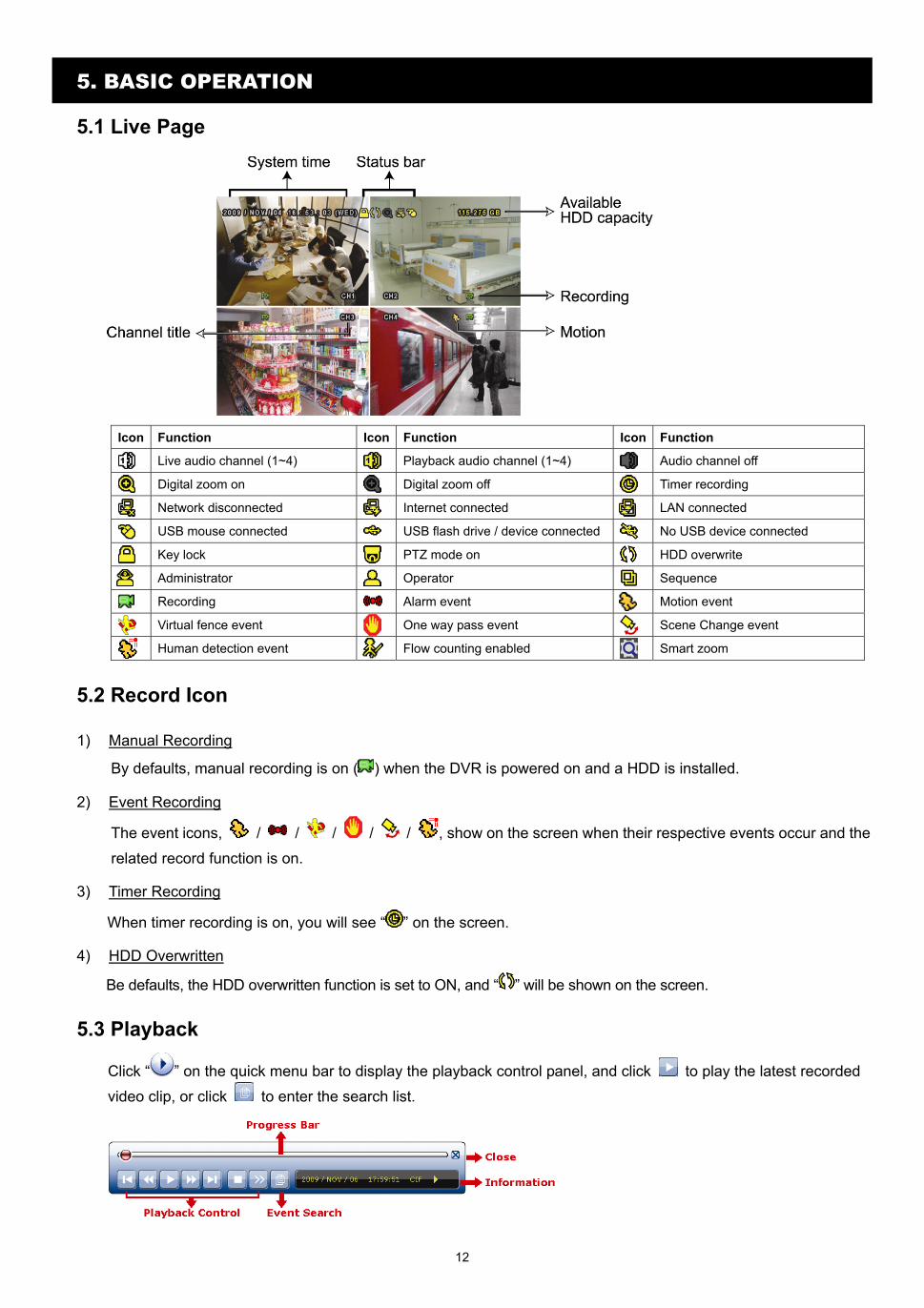
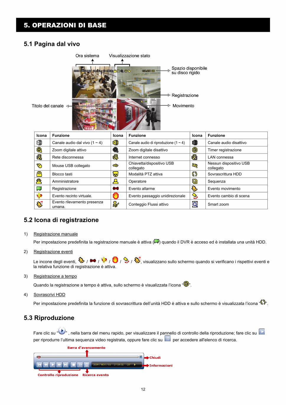
5.1 Live Page
Icon Function Icon Function Icon Function
Live audio channel (1~4) Playback audio channel (1~4) Audio channel off
Digital zoom on Digital zoom off Timer recording
Network disconnected Internet connected LAN connected
USB mouse connected USB flash drive / device connected No USB device connected
Key lock PTZ mode on HDD overwrite
Administrator Operator Sequence
Recording Alarm event Motion event
Virtual fence event One way pass event Scene Change event
Human detection event Flow counting enabled Smart zoom
5.2 Record Icon
1) Manual Recording
By defaults, manual recording is on ( ) when the DVR is powered on and a HDD is installed.
2) Event Recording
The event icons, / / / / / , show on the screen when their respective events occur and the
related record function is on.
3) Timer Recording
When timer recording is on, you will see “ ” on the screen.
4) HDD Overwritten
Be defaults, the HDD overwritten function is set to ON, and “ ” will be shown on the screen.
5.3 Playback
Click “ ” on the quick menu bar to display the playback control panel, and click to play the latest recorded
video clip, or click to enter the search list.
13
Note: There must be at least 8192 images of recorded data for playback to work properly. If not, the device will stop playback. For example, if the IPS is set to 30, the recording time should be at least 273 seconds (8192 images / 30 IPS) for the playback to work properly.
Note: During playback, the image size of the recording (FRAME, FIELD or CIF) will be shown on the
screen.
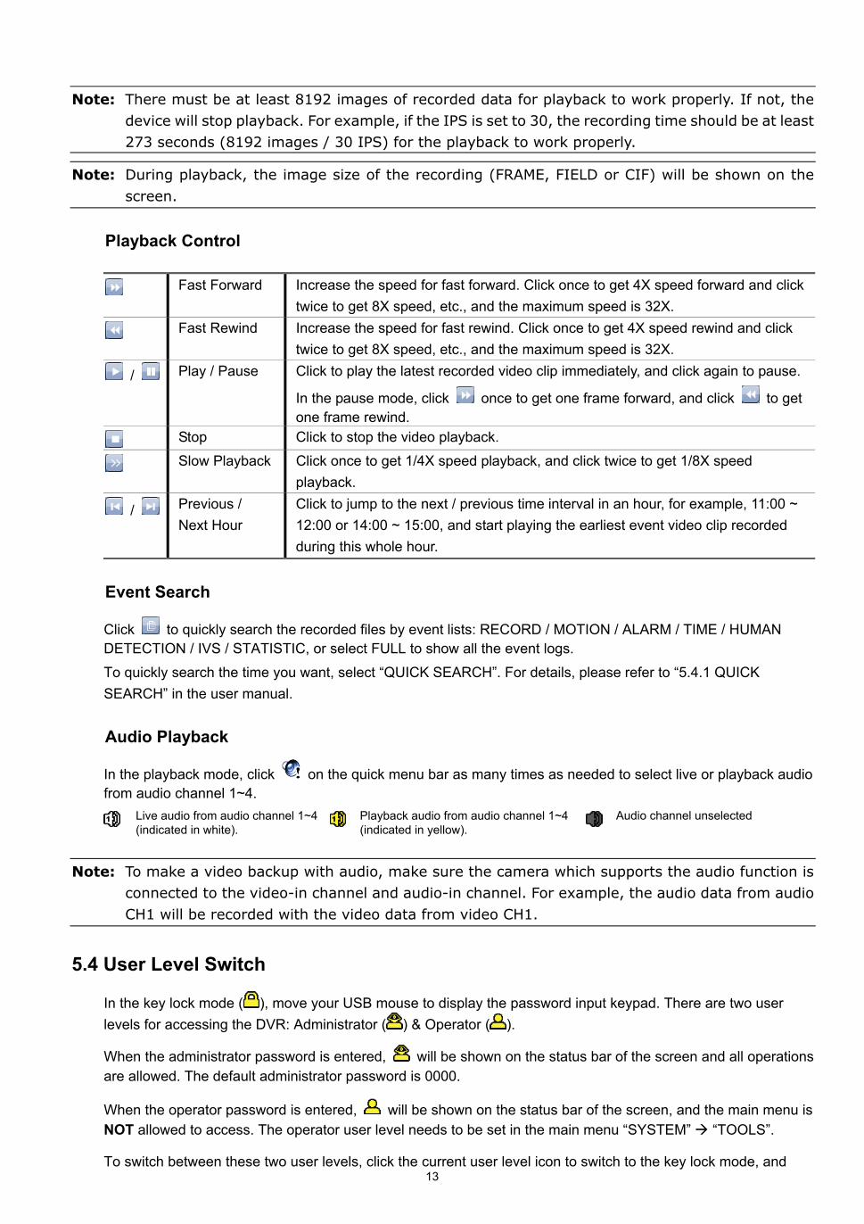
Playback Control
Fast Forward Increase the speed for fast forward. Click once to get 4X speed forward and click twice to get 8X speed, etc., and the maximum speed is 32X.
Fast Rewind Increase the speed for fast rewind. Click once to get 4X speed rewind and click twice to get 8X speed, etc., and the maximum speed is 32X.
/ Play / Pause Click to play the latest recorded video clip immediately, and click again to pause.
In the pause mode, click once to get one frame forward, and click to get one frame rewind.
Stop Click to stop the video playback.
Slow Playback Click once to get 1/4X speed playback, and click twice to get 1/8X speed playback.
/ Previous / Next Hour
Click to jump to the next / previous time interval in an hour, for example, 11:00 ~ 12:00 or 14:00 ~ 15:00, and start playing the earliest event video clip recorded during this whole hour.
Event Search
Click to quickly search the recorded files by event lists: RECORD / MOTION / ALARM / TIME / HUMAN DETECTION / IVS / STATISTIC, or select FULL to show all the event logs.
To quickly search the time you want, select “QUICK SEARCH”. For details, please refer to “5.4.1 QUICK SEARCH” in the user manual.
Audio Playback
In the playback mode, click on the quick menu bar as many times as needed to select live or playback audio from audio channel 1~4.
Live audio from audio channel 1~4 (indicated in white).
Playback audio from audio channel 1~4 (indicated in yellow).
Audio channel unselected
Note: To make a video backup with audio, make sure the camera which supports the audio function is
connected to the video-in channel and audio-in channel. For example, the audio data from audio CH1 will be recorded with the video data from video CH1.
5.4 User Level Switch
In the key lock mode ( ), move your USB mouse to display the password input keypad. There are two user levels for accessing the DVR: Administrator ( ) & Operator ( ).
When the administrator password is entered, will be shown on the status bar of the screen and all operations are allowed. The default administrator password is 0000.
When the operator password is entered, will be shown on the status bar of the screen, and the main menu is NOT allowed to access. The operator user level needs to be set in the main menu “SYSTEM” “TOOLS”.
To switch between these two user levels, click the current user level icon to switch to the key lock mode, and
14
move your mouse to show the password input keypad, and enter the password of the user level you want.
5.5 Video Output Switch
It’s not allowed to have video output simultaneously on a CRT monitor (connected to MONITOR) and LCD monitor (connected to VGA).
The default video output setting is “AUTO”, meaning the DVR will automatically detect the video output source. When VGA and MONITOR are both connected, the default monitor output is VGA.
To change the video output setting manually: To force the video output via MONITOR, press the left key on the DVR front panel at DVR power-on. To force the video output via VGA, press the right key on the DVR front panel at DVR power-on.
The setting is changed when you hear a short beep sound.
OR:
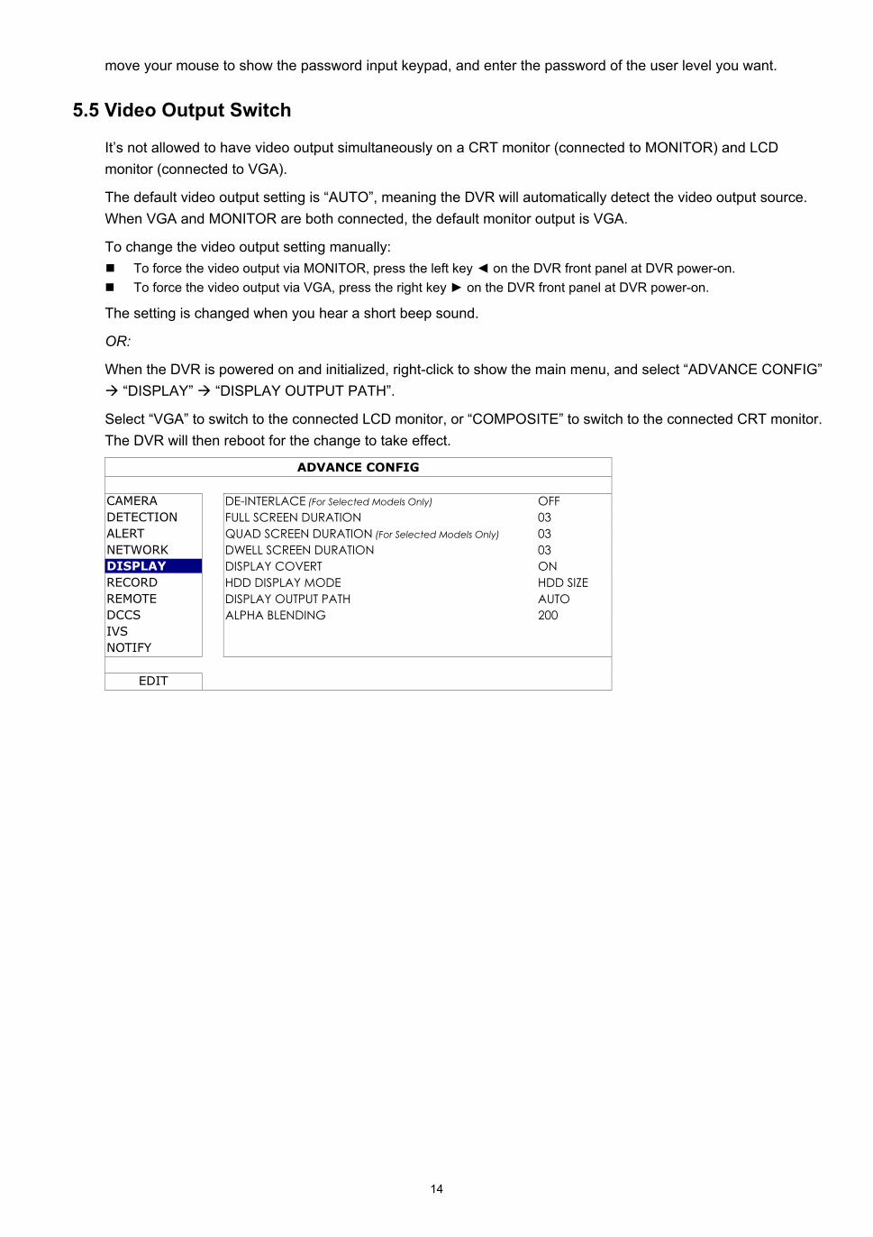
When the DVR is powered on and initialized, right-click to show the main menu, and select “ADVANCE CONFIG” “DISPLAY” “DISPLAY OUTPUT PATH”.
Select “VGA” to switch to the connected LCD monitor, or “COMPOSITE” to switch to the connected CRT monitor. The DVR will then reboot for the change to take effect.
ADVANCE CONFIG
CAMERA DE-INTERLACE (For Selected Models Only) OFF DETECTION FULL SCREEN DURATION 03 ALERT QUAD SCREEN DURATION (For Selected Models Only) 03 NETWORK DWELL SCREEN DURATION 03 DISPLAY DISPLAY COVERT ON RECORD HDD DISPLAY MODE HDD SIZE REMOTE DISPLAY OUTPUT PATH AUTO DCCS ALPHA BLENDING 200 IVS NOTIFY
EDIT
15
APPENDIX 1. SET IPHONE PUSH NOTIFICATION
This IVS DVR series supports instant event notifications to your iPhone with our self-developed program, “EagleEyes”, installed. When a man is detected by a human detection camera, the DVR will immediately receive alarm signals and send to your iPhone.
Note: iPhone is the registered trademark of Apple Inc.
Note: EagleEyes is a powerful mobile surveillance program developed by AV TECH Corporation. For more
operations details about EagleEyes, please visit http://www.eagleeyescctv.com. For any comment or question about this program, please send to [email protected]. Your feedback is always welcomed.
You need to finish some settings in your iPhone for this function to work properly. For details, please refer to “A1.2.2 Program Setup” at page 16.
A1.1 Prerequisite
Before setting this function, make sure you have checked the following:
You have an iPhone with our self-developed program, “EagleEyes”, installed. For details, please refer to “A1.2.1 Program Download” at page 15.
A human detection camera is connected to your IVS DVR.
The event record function of your IVS DVR is not disabled.
The motion detection function of your IVS DVR is not disabled.
Your IVS DVR is connected to Internet. For details, please refer to
http://www.surveillance-download.com/user/CMS.pdf.
A1.2 Set iPhone
A1.2.1 Program Download
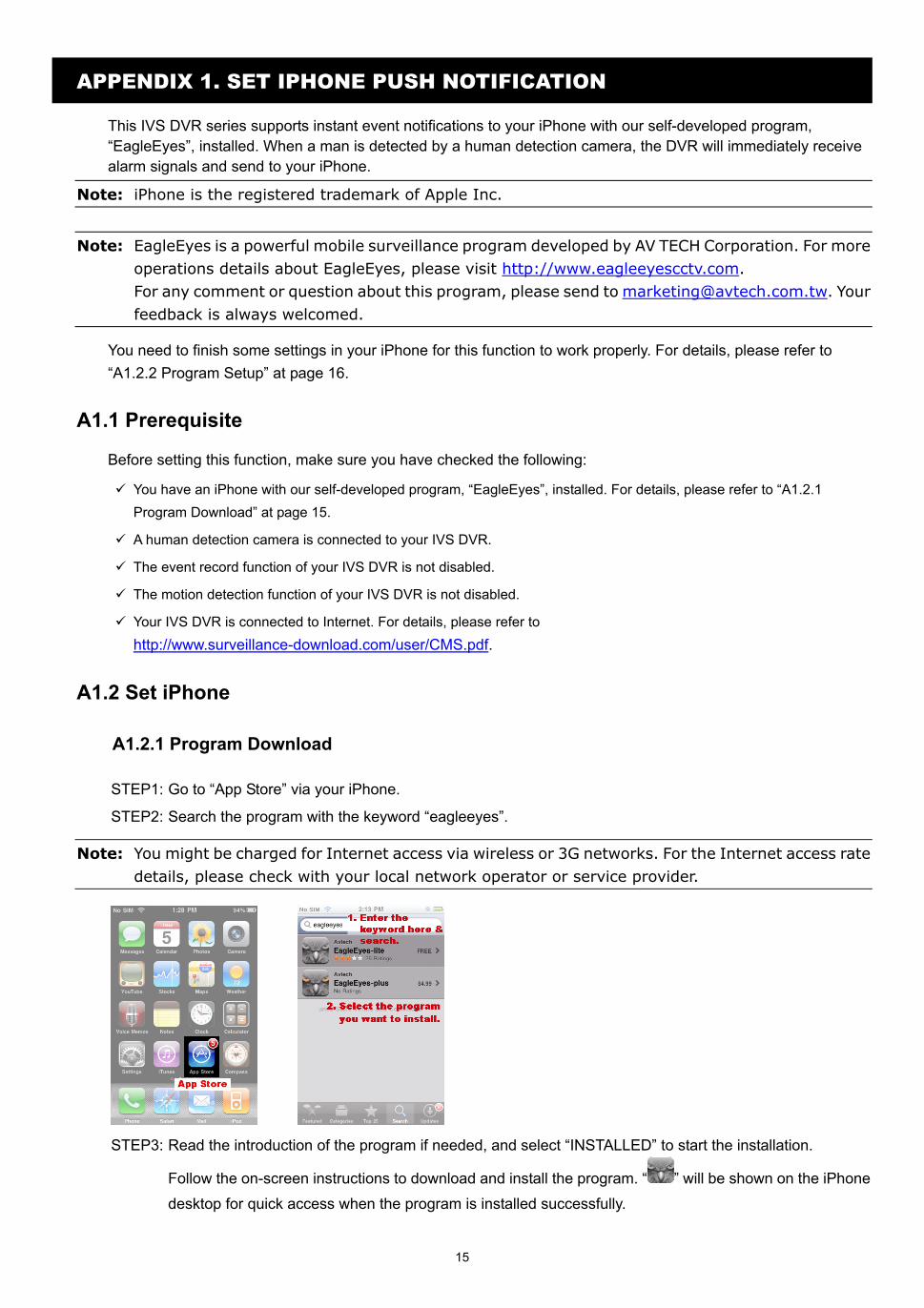
STEP1: Go to “App Store” via your iPhone.
STEP2: Search the program with the keyword “eagleeyes”.
Note: You might be charged for Internet access via wireless or 3G networks. For the Internet access rate
details, please check with your local network operator or service provider.
STEP3: Read the introduction of the program if needed, and select “INSTALLED” to start the installation.
Follow the on-screen instructions to download and install the program. “ ” will be shown on the iPhone
desktop for quick access when the program is installed successfully.
16
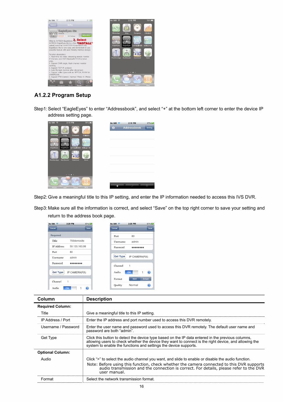
A1.2.2 Program Setup
Step1: Select “EagleEyes” to enter “Addressbook”, and select “+” at the bottom left corner to enter the device IP address setting page.
Step2: Give a meaningful title to this IP setting, and enter the IP information needed to access this IVS DVR.
Step3: Make sure all the information is correct, and select “Save” on the top right corner to save your setting and
return to the address book page.
Column Description Required Column:
Title Give a meaningful title to this IP setting.
IP Address / Port Enter the IP address and port number used to access this DVR remotely.
Username / Password Enter the user name and password used to access this DVR remotely. The default user name and password are both “admin”.
Get Type Click this button to detect the device type based on the IP data entered in the previous columns, allowing users to check whether the device they want to connect is the right device, and allowing the system to enable the functions and settings the device supports.
Optional Column:
Audio Click “>” to select the audio channel you want, and slide to enable or disable the audio function. Note: Before using this function, check whether the camera connected to this DVR supports
audio transmission and the connection is correct. For details, please refer to the DVR user manual.
Format Select the network transmission format.
17
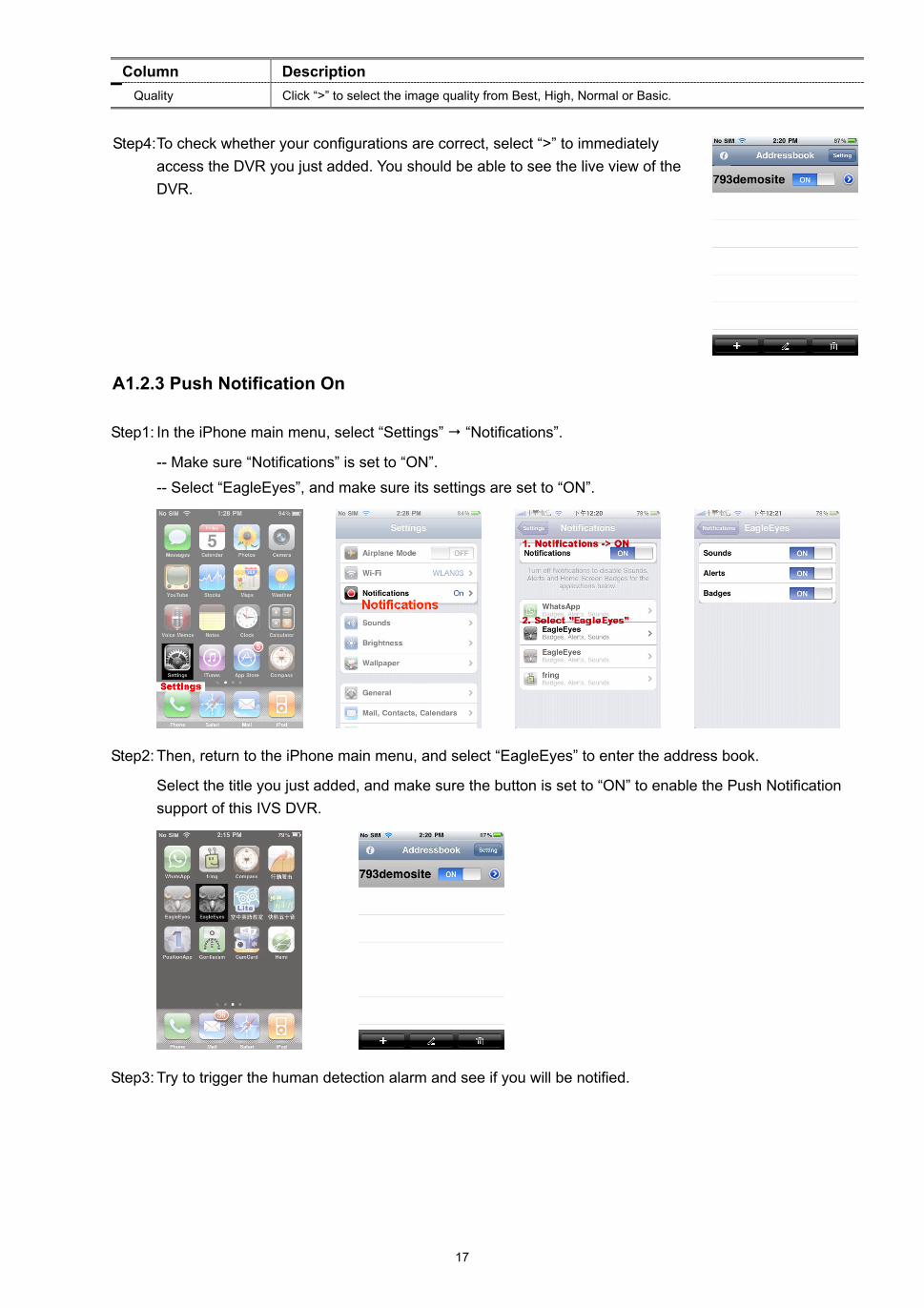
Column Description Quality Click “>” to select the image quality from Best, High, Normal or Basic.
Step4: To check whether your configurations are correct, select “>” to immediately
access the DVR you just added. You should be able to see the live view of the DVR.
A1.2.3 Push Notification On
Step1: In the iPhone main menu, select “Settings” “Notifications”.
-- Make sure “Notifications” is set to “ON”.
-- Select “EagleEyes”, and make sure its settings are set to “ON”.
Step2: Then, return to the iPhone main menu, and select “EagleEyes” to enter the address book.
Select the title you just added, and make sure the button is set to “ON” to enable the Push Notification support of this IVS DVR.
Step3: Try to trigger the human detection alarm and see if you will be notified.
18
APPENDIX 2. SET FLOW COUNTING / VIRTUAL FENCE / ONE-WAY PASS
IVS, Intelligent Video Surveillance, is the advanced application for motion detection, but more precise and smarter. It can be applied to different situations with one of the following three modes: FLOW COUNTING, VIRTUAL FENCE, and ONE WAY PASS.
Note: Four camera channels are supported for this function. For 16CH and 8CH models, users are allowed to select four camera channels randomly to use this function; for 4CH models, all the four camera channels are supported.
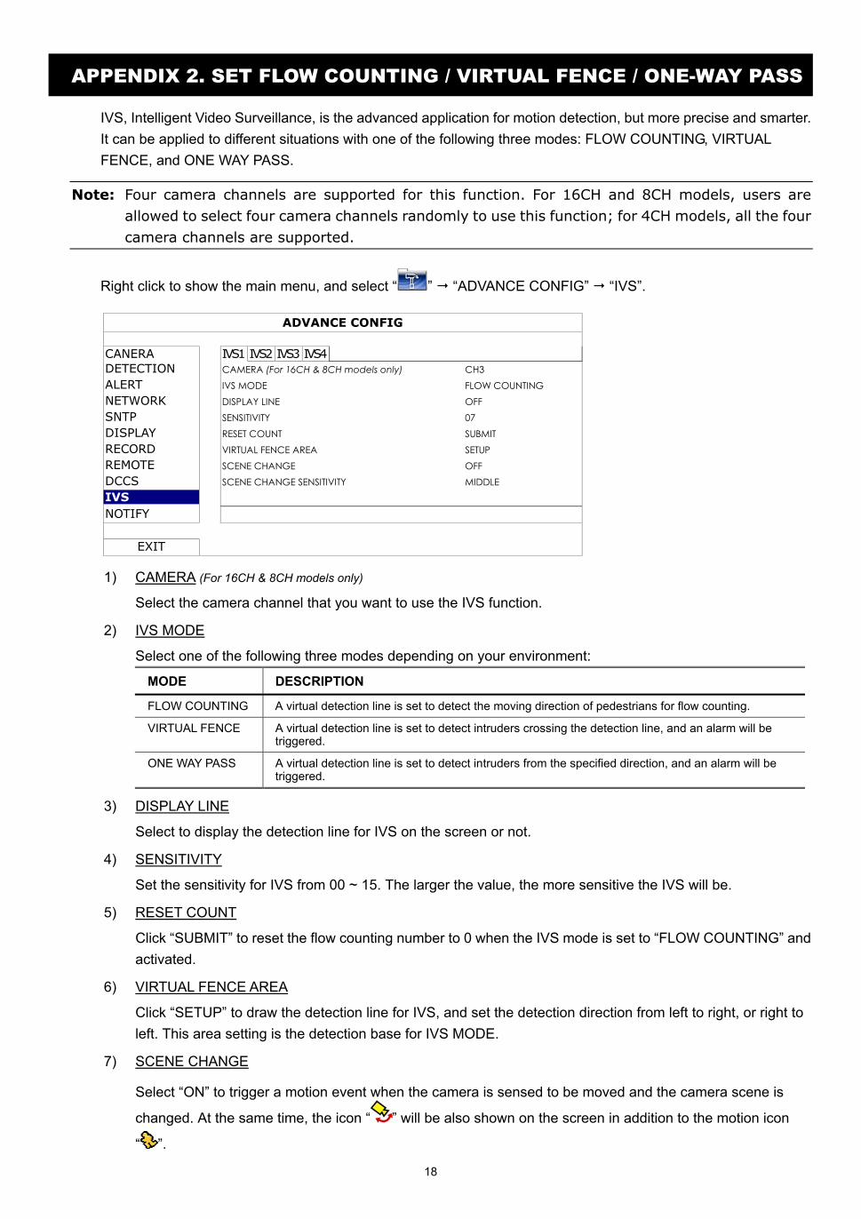
Right click to show the main menu, and select “ ” “ADVANCE CONFIG” “IVS”.
ADVANCE CONFIG
CANERA IVS1 IVS2 IVS3 IVS4 DETECTION CAMERA (For 16CH & 8CH models only) CH3 ALERT IVS MODE FLOW COUNTING NETWORK DISPLAY LINE OFF SNTP SENSITIVITY 07 DISPLAY RESET COUNT SUBMIT RECORD VIRTUAL FENCE AREA SETUP REMOTE SCENE CHANGE OFF DCCS SCENE CHANGE SENSITIVITY MIDDLE IVS
NOTIFY
EXIT
1) CAMERA (For 16CH & 8CH models only)
Select the camera channel that you want to use the IVS function.
2) IVS MODE
Select one of the following three modes depending on your environment:
MODE DESCRIPTION
FLOW COUNTING A virtual detection line is set to detect the moving direction of pedestrians for flow counting.
VIRTUAL FENCE A virtual detection line is set to detect intruders crossing the detection line, and an alarm will be triggered.
ONE WAY PASS A virtual detection line is set to detect intruders from the specified direction, and an alarm will be triggered.
3) DISPLAY LINE
Select to display the detection line for IVS on the screen or not.
4) SENSITIVITY
Set the sensitivity for IVS from 00 ~ 15. The larger the value, the more sensitive the IVS will be.
5) RESET COUNT
Click “SUBMIT” to reset the flow counting number to 0 when the IVS mode is set to “FLOW COUNTING” and activated.
6) VIRTUAL FENCE AREA
Click “SETUP” to draw the detection line for IVS, and set the detection direction from left to right, or right to left. This area setting is the detection base for IVS MODE.
7) SCENE CHANGE
Select “ON” to trigger a motion event when the camera is sensed to be moved and the camera scene is
changed. At the same time, the icon “ ” will be also shown on the screen in addition to the motion icon
“ ”.
19
8) SCENE CHANGE SENSITIVITY
Set the detection sensitivity for “SCENE CHANGE” to “HIGH”, “MIDDLE” or “LOW”.
A2.1 IVS APPLICATION
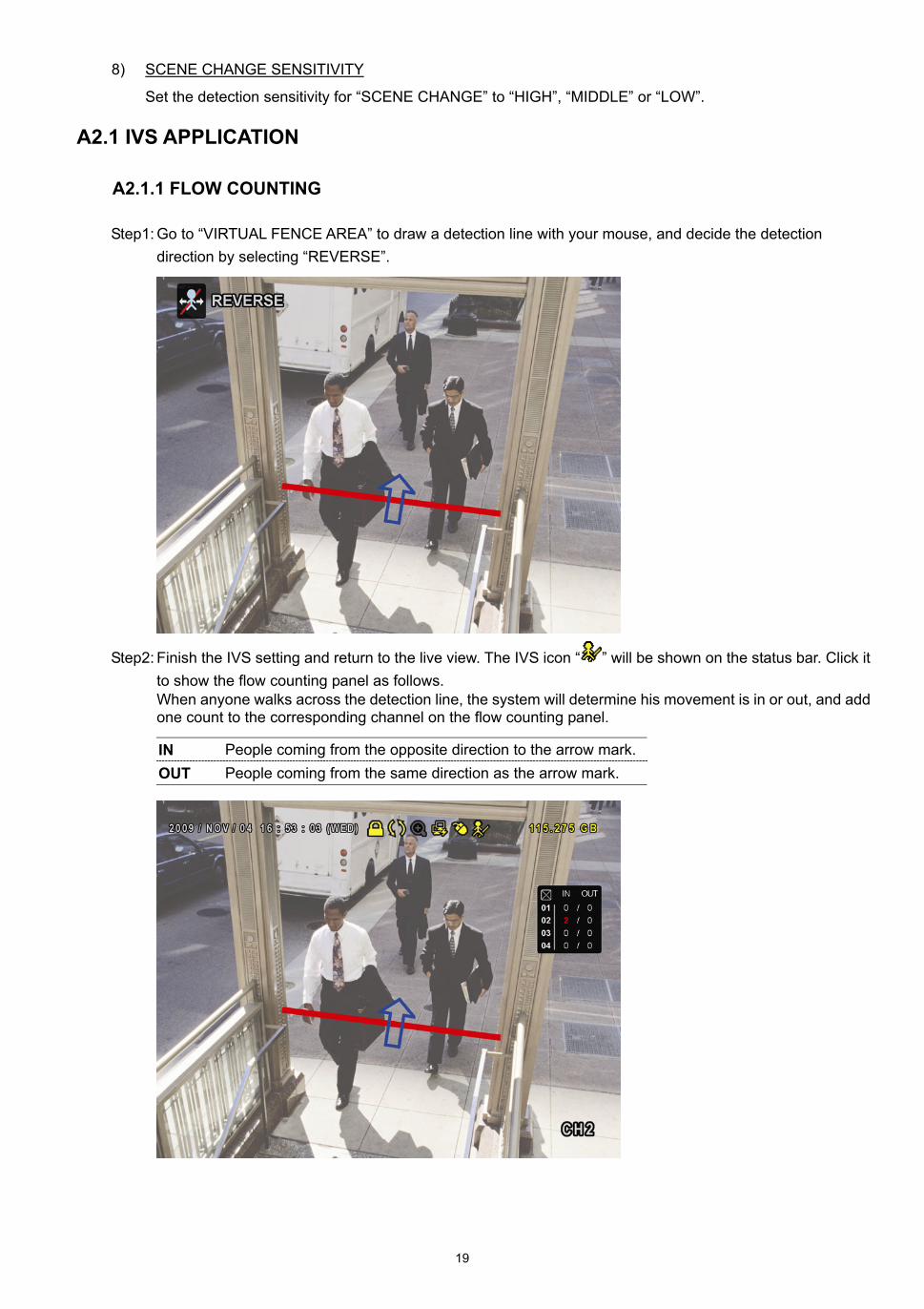
A2.1.1 FLOW COUNTING
Step1: Go to “VIRTUAL FENCE AREA” to draw a detection line with your mouse, and decide the detection direction by selecting “REVERSE”.
Step2: Finish the IVS setting and return to the live view. The IVS icon “ ” will be shown on the status bar. Click it to show the flow counting panel as follows. When anyone walks across the detection line, the system will determine his movement is in or out, and add one count to the corresponding channel on the flow counting panel.
IN People coming from the opposite direction to the arrow mark.OUT People coming from the same direction as the arrow mark.
20
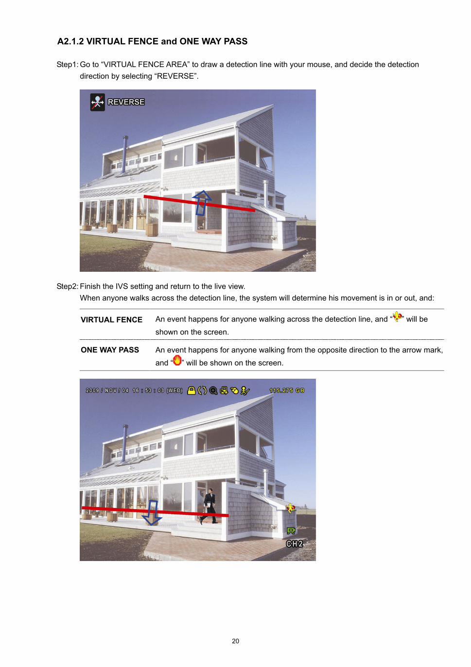
A2.1.2 VIRTUAL FENCE and ONE WAY PASS
Step1: Go to “VIRTUAL FENCE AREA” to draw a detection line with your mouse, and decide the detection direction by selecting “REVERSE”.
Step2: Finish the IVS setting and return to the live view. When anyone walks across the detection line, the system will determine his movement is in or out, and:
VIRTUAL FENCE An event happens for anyone walking across the detection line, and “ ” will be
shown on the screen.
ONE WAY PASS An event happens for anyone walking from the opposite direction to the arrow mark,
and “ ” will be shown on the screen.
21
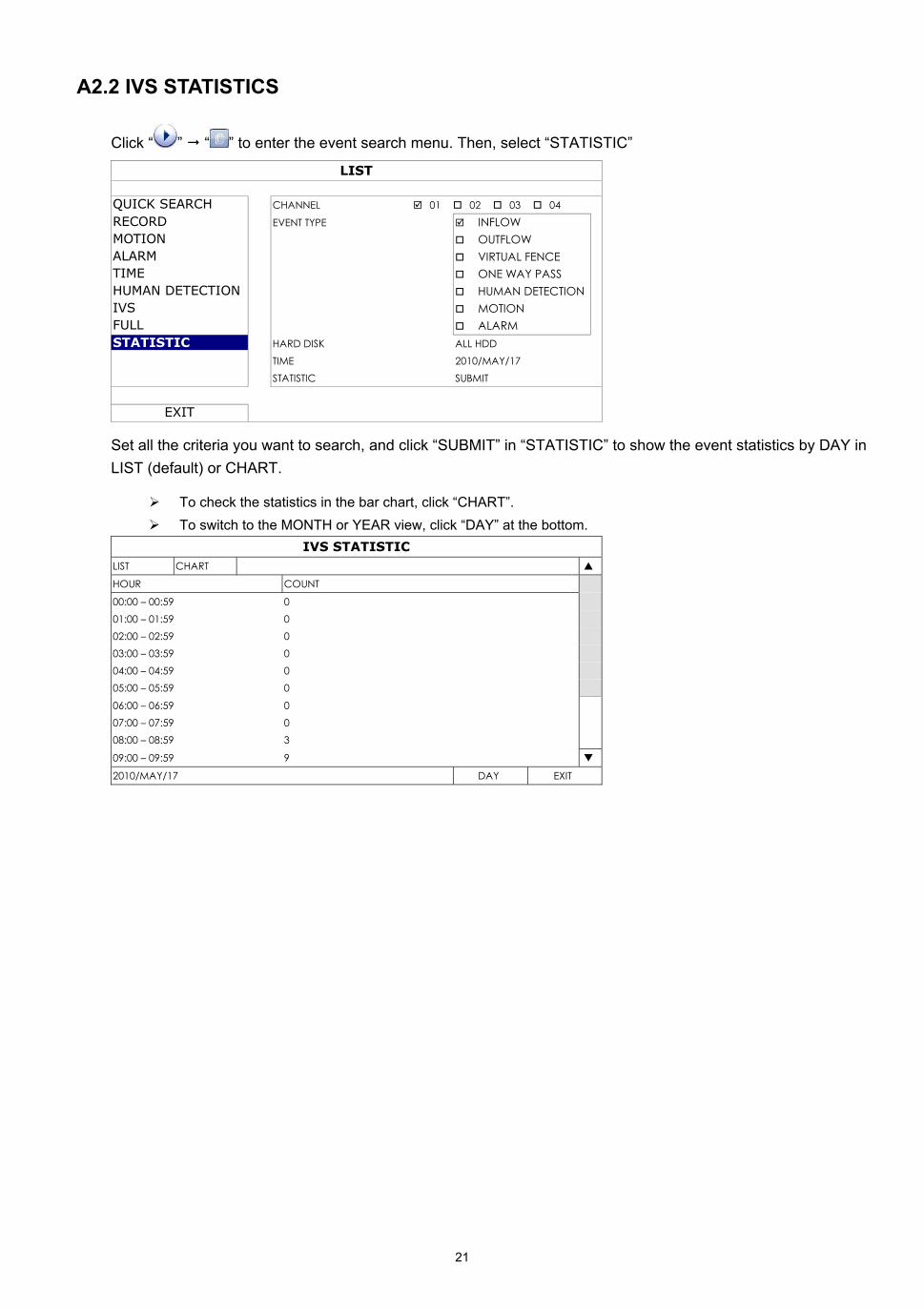
A2.2 IVS STATISTICS
Click “ ” “ ” to enter the event search menu. Then, select “STATISTIC”
LIST
QUICK SEARCH CHANNEL 01 02 03 04
RECORD EVENT TYPE INFLOW MOTION OUTFLOW ALARM VIRTUAL FENCE TIME ONE WAY PASS HUMAN DETECTION HUMAN DETECTION IVS MOTION FULL ALARM
STATISTIC HARD DISK ALL HDD TIME 2010/MAY/17 STATISTIC SUBMIT
EXIT
Set all the criteria you want to search, and click “SUBMIT” in “STATISTIC” to show the event statistics by DAY in LIST (default) or CHART.
To check the statistics in the bar chart, click “CHART”. To switch to the MONTH or YEAR view, click “DAY” at the bottom.
IVS STATISTIC LIST CHART
HOUR COUNT
00:00 – 00:59 0 01:00 – 01:59 0 02:00 – 02:59 0 03:00 – 03:59 0 04:00 – 04:59 0 05:00 – 05:59 0
06:00 – 06:59 0 07:00 – 07:59 0 08:00 – 08:59 3
09:00 – 09:59 9
2010/MAY/17 DAY EXIT
353Z
Italian_D748_746_744_Guida all’installazione_V1.1
Guida all’installazione
Video Sorveglianza Intelligente Interfaccia grafica con controllo mouse USB
Leggere accuratamente le istruzioni prima dell’uso e conservarle per riferimenti futuri.
Fare riferimento al DVR impiegato per le schermate e le operazioni effettive.
IMPORTANTI ISTRUZIONI DI SICUREZZA
ATTENZIONE
RISCHIO DI FOLGORAZIONE
ATTENZIONE: Per ridurre il rischio di folgorazione, non esporre l’apparecchio a pioggia o umidità. Usare solo con il tipo di alimentazione elettrica indicata sull’etichetta. La società non deve essere ritenuta responsabile di qualsiasi danno derivante da uso improprio, anche se siamo stati avvisati della possibilità di tali danni.
Il simbolo del fulmine all’interno di un triangolo equilatero serve per avvertire l’utente della presenza di “tensioni pericolose” non isolate all’interno del prodotto, che possono essere di magnitudine tale da costituire un rischio scosse elettriche per le persone.
Il punto esclamativo, all’interno di un triangolo equilatero, e inteso per avvisare l’utente della presenza di importanti istruzioni operative e di manutenzione (riparazioni) nella documentazione che accompagna l’attrezzatura.
Tutti i prodotti senza piombo forniti dall’azienda sono conformi ai requisiti delle Leggi Europee in materia di restrizione dell’uso di determinate sostanze pericolose all’interno delle apparecchiature elettriche ed elettroniche (RoHS), questo significa che le nostre procedure di produzione ed in nostri prodotti sono rigorosamente “senza piombo” e privi delle sostanze citate nella Direttiva.
Il simbolo del bidone della spazzatura annullato da una croce, indica che all’interno dell’Unione Europea il prodotto deve essere smaltito separatamente dai rifiuti urbani al termine della sua durata utile. Questo vale per il prodotto e per tutte le periferiche marcate con questo simbolo. Non smaltire questi prodotti indistintamente insieme ai rifiuti urbani. Contattare il proprio rivenditore locale per le procedure di riciclaggio dell’apparecchio
Questo apparato e prodotto in conformità ai requisiti sulle interferenze radio.
Informazioni sui Marchi
e (EagleEyes) - La richiesta di registrazione del marchio è stata completata ed è attaualmente in corso negli Stati Uniti ed in altri paesi.
iPhone® è un marchio registrato di Apple Inc., e Apple detiene i diritti sulla proprietà intellettuale dei contenuti di iPhone.
Limitazione delle responsabilità
Le informazioni di questo Manuale erano aggiornate al momento della pubblicazione. Ci riserviamo il diritto di rivedere o rimuovere, in qualsiasi momento, qualsiasi contenuto di questo manuale. Non facciamo garanzie, né ci assumiamo alcuna responsabilità legale nei riguardi dell’accuratezza, completezza o utilità di questo manuale. Fare riferimento al DVR impiegato per le schermate e le operazioni effettive. I contenuti di questo manuale sono soggetti a modifica senza preavviso.
Messa a terra
Questo è un prodotto di sicurezza di Classe 1 (dotato di messa a terra protettiva incorporata nel cavo d’alimentazione). La spina elettrica deve essere inserita esclusivamente in una presa di corrente dotata di contatto di messa a terra. Qualsiasi interruzione del conduttore protettivo, all’interno o all’esterno dello strumento, lo renderà pericoloso. L’interruzione intenzionale è proibita.
Acqua e Umidità
Non esporre questo prodotto a gocciolamenti o spruzzi; inoltre, sul prodotto non devono essere collocati oggetti riempiti con liquidi, come vasi.
Licenza MPEG4
QUESTO PRODOTTO È SOTTO LA LICENZA DEL PORTAFOGLIO LICENZE DI BREVETTI MPEG-4 VISUAL PER USO PERSONALE NON COMMERCIALE DEGLI UTENTI PER LA (i) CODIFICA VIDEO IN CONFORMITÀ ALLO STANDARD MPEG-4 VISUAL (“VIDEO MPEG-4”) E/O (ii) LA DECODIFICA VIDEO MPEG-4 CHE È STATO CODIFICATO DA UN UTENTE IMPEGNATO IN UNA ATTIVITÀ PERSONALE E NON COMMERCIALE E/O CHE È STATO OTTENUTO DA UN FORNITORE VIDEO AUTORIZZATO DA MPEG LA A FORNIRE VIDEO MPEG-4. NESSUNA ALTRA LICENZA E GARANTITA, NE DEVE CONSIDERASI IMPLICITA, PER QUALSIASI ALTRO USO. ALTRE INFORMAZIONI, INCLUDENDO QUELLE RELATIVE AD USI PROMOZIONALI INTERNI E COMMERCIALI ED ALLE CONCESSIONI DI LICENZA, POSSONO ESSERE OTTENUTE DALLA MPEG LA, LLC. VISITARE IL SITO HTTP://WWW.MPEGLA.COM.
Licenza GPL
Questo prodotto contiene codici che sono sviluppati da Terze Parti e che sono soggette a GNU General Public License (“GPL”) o a GNU Lesser Public Licence (“LGPL”). Il codice GPL utilizzato in questo prodotto viene rilasciato senza alcuna garanzia ed è soggetto al copyright dell’autore.Ulteriori codici sorgente soggetti a licenze GPL, sono disponibili su richiesta. Siamo lieti di fornire le nostre modifiche al Linux Kernel, oltre ad alcuni comandi nuovi, ed alcuni strumenti per accedere al codice. I codici sono disponibili sul sito FTP, si raccomanda di scaricarli dal seguente sito oppure consultare il proprio distributore: ftp://ftp.dvrtw.com.tw/GPL/AV074/
CONTENUTI
1. DESCRIZIONE DEL PRODOTTO............................................................................................ 1
2. COLLEGAMENTI E CONFIGURAZIONE ................................................................................ 2
2.1 Prerequisiti .........................................................................................................................................................................2 2.2 Installazione di un disco rigido SATA.................................................................................................................................2 2.3 Installazione della telecamera DCCS (telecamera controllabile) .......................................................................................3 2.4 Collegamento della telecamera DCCS (telecamera controllabile) .....................................................................................3 2.5 Accensione del DVR ..........................................................................................................................................................4 2.6 Impostazione di data e ora.................................................................................................................................................4 2.7 Cancellazione del disco rigido............................................................................................................................................4 2.8 Impostazione password .....................................................................................................................................................5 2.9 Esame della trasmissione del segnale...............................................................................................................................5 2.10 Configurazione della telecamera DCCS (telecamera controllabile) .................................................................................6
2.10.1 Per una telecamera PTZ: .....................................................................................................................................6 2.10.2 Per telecamere con il controllo dell’obiettivo dello zoom......................................................................................6
3. INTERFACCIA GRAFICA CON CONTROLLO MOUSE USB ................................................. 7
3.1 Collegamento del mouse USB ...........................................................................................................................................7 3.2 Barra del menu rapido........................................................................................................................................................7 3.3 Menu Principale .................................................................................................................................................................8
Struttura del menu principale...........................................................................................................................................8
4. PANNELLO FRONTALE E POSTERIORE ............................................................................ 10
4.1 Pannello frontale ..............................................................................................................................................................10 4.2 Pannello posteriore ..........................................................................................................................................................11
5. OPERAZIONI DI BASE.......................................................................................................... 12
5.1 Pagina dal vivo.................................................................................................................................................................12 5.2 Icona di registrazione .......................................................................................................................................................12 5.3 Riproduzione ....................................................................................................................................................................12
Controllo riproduzione ...................................................................................................................................................13 Ricerca evento ..............................................................................................................................................................13 Riproduzione Audio .......................................................................................................................................................13
5.4 Cambio di livello dell’utente..............................................................................................................................................13 5.5 Cambio dell’uscita video ..................................................................................................................................................14
APPENDICE 1. IMPOSTARE LA PUSH NOTIFICATION IPHONE ........................................... 15
A1.1 Prerequisito....................................................................................................................................................................15 A1.2 Impostare iPhone...........................................................................................................................................................15
A1.2.1 Download del Programma..................................................................................................................................15 A1.2.2 Setup Programma..............................................................................................................................................16 A1.2.3 Push Notification On (Notifica Immediata Abilitata)............................................................................................17
APPENDICE 2. IMPOSTARE CONTEGGIO FLUSSI / PASSAGGIO VIRTUALE / PASSAGGIO UNIDIREZIONALE..................................................................... 18
A2.1 APPLICAZIONE IVS......................................................................................................................................................19 A2.1.1 CONTEGGIO FLUSSI........................................................................................................................................19 A2.1.2 PASSAGGIO VIRTUALE e PASSAGGIO UNIDIREZIONALE ...........................................................................20
A2.2 STATISTICHE IVS.........................................................................................................................................................21
1
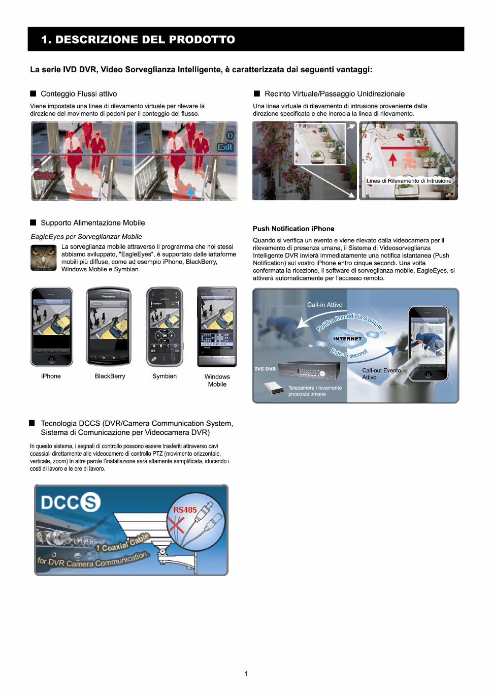
1. DESCRIZIONE DEL PRODOTTO
2
2. COLLEGAMENTI E CONFIGURAZIONE Prima di accendere il DVR, assicurarsi di avere installato il disco rigido, e di avere collegato almeno una telecamera e un monitor. Fare riferimento alle sezioni che seguono per i dettagli.
Nota: Il DVR è progettato per rilevare automaticamente il sistema video delle telecamere collegate (NTSC o PAL). Per accertarsi che il rilevamento del sistema sia corretto, controllare che le telecamere siano collegate al DVR e che siano alimentate prima di accendere il DVR.
Nota: I collegamenti e la configurazione descritti di seguito si riferiscono esclusivamente a dispositivi DCCS (Telecamere controllabili). Per informazioni sul collegamento di altre telecamere, non DCCS (telecamere controllabili), fare riferimento al manuale utente del DVR.
2.1 Prerequisiti
Controllare la le telecamere supportanto la funzione DCCS (telecamera controllabile). Per avere informazioni rivolgersi all’installatore o al distributore.
Per garantire la trasmissione del segnale, la distanza consigliata tra questo DVR e le telecamere non deve essere superiore ai 200 metri usando cavi coassiali 3C2V (112 fili).
Tuttavia, i materiali diversi utilizzati nei cavi coassiali 3C2V, in relazione alle diverse distanze di collegamento, possono influenzare la disponibilità e la fluidità della trasmissione del segnale.
Pertanto, eseguire il test DCCS (telecamera controllabile) come da istruzioni in “2,9 Esame della trasmissione del segnale” a pagina 5 una volta completata la connessione per accertarsi che il sistema possa funzionare in modo corretto.
Non è possibile utilizzare un amplificatore del segnale o un modem per amplificare i segnali e aumentare la distanza di collegamento.
La funzione DCCS (telecamera controllabile) non supporta il canale che è in loop da una telecamera DCCS (telecamera controllabile) colelgata allo stesso DCCS DVR o a un altro DCCS DVR.
2.2 Installazione di un disco rigido SATA
Prima di accendere il DVR deve essere installata una unità HDD SATA.
Nota: Si raccomanda di cancellare tutti i dati del disco rigido quando il DVR è acceso e di accertarsi che la data e l’ora siano impostate correttamente per garantire che i dati registrati non siano confusi con dati registrati e salvati in precedenza sullo stesso disco rigido. Fare riferimento alla sezione “2,7 Cancellazione del disco rigido”, a pagina 4, per i dettagli.
Per il modelli a 16 CH e 8 CH
Fase 1: Allentare le viti sulla copertura superiore del DVR ed aprirla.
Nota: La copertura del DVR è di metallo. Prestare attenzione ai bordi quando si rimuove la copertura.
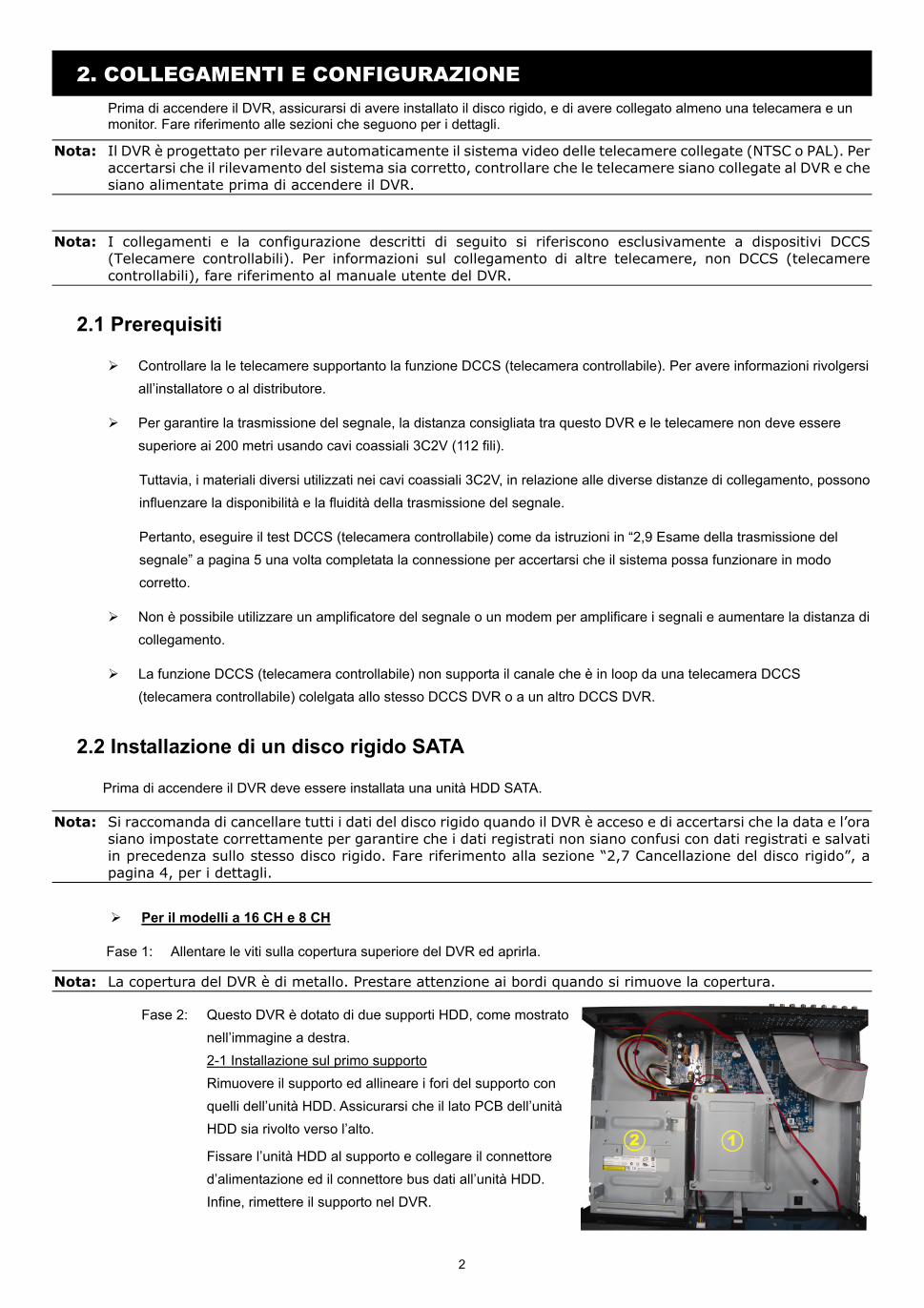
Fase 2: Questo DVR è dotato di due supporti HDD, come mostrato nell’immagine a destra. 2-1 Installazione sul primo supporto Rimuovere il supporto ed allineare i fori del supporto con quelli dell’unità HDD. Assicurarsi che il lato PCB dell’unità HDD sia rivolto verso l’alto.
Fissare l’unità HDD al supporto e collegare il connettore d’alimentazione ed il connettore bus dati all’unità HDD. Infine, rimettere il supporto nel DVR.
3
2-2 Installazione sul secondo supporto Collegare il connettore d’alimentazione ed il connettore bus dati all’unità HDD.
Quando si collega il cavo d’alimentazione, assicurarsi di farlo passare attraverso il cavo d’alimentazione del masterizzatore DVD. Questo impedisce al cavo d’alimentazione dell’unità HDD di interferire col movimento della ventola.
Allineare i fori del supporto con quelli dell’unità HDD. Assicurarsi che il lato PCB dell’unità HDD sia rivolto verso l’alto. Infine, fissare l’unità HDD al supporto.
Fase 3: Chiudere la copertura superiore del DVR e stringere tutte le viti allentate nella Fase 1.
Per il modello 4 CH
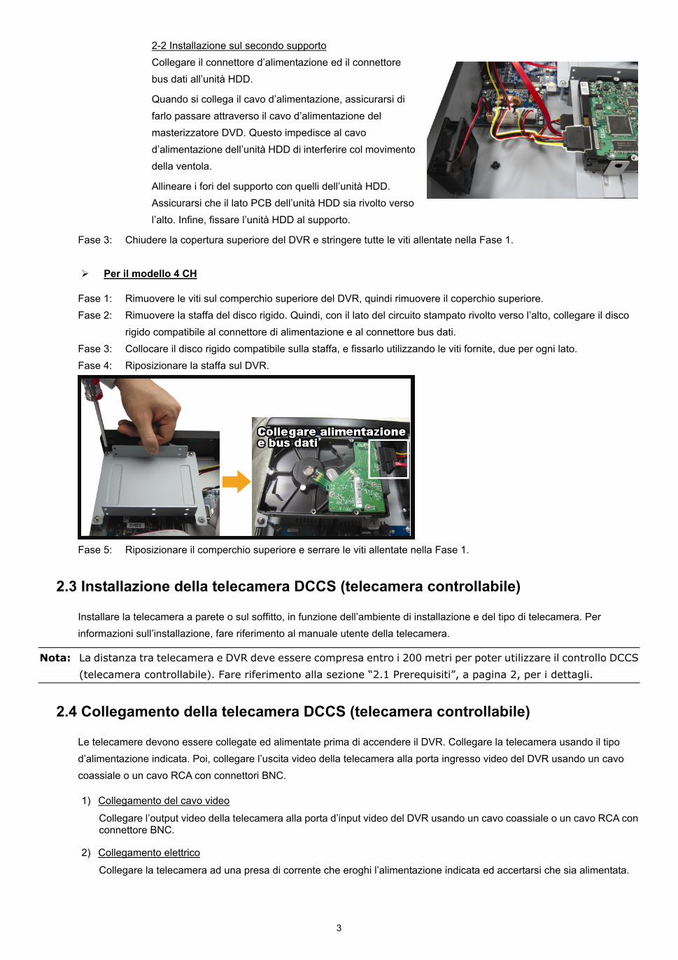
Fase 1: Rimuovere le viti sul comperchio superiore del DVR, quindi rimuovere il coperchio superiore. Fase 2: Rimuovere la staffa del disco rigido. Quindi, con il lato del circuito stampato rivolto verso l’alto, collegare il disco
rigido compatibile al connettore di alimentazione e al connettore bus dati. Fase 3: Collocare il disco rigido compatibile sulla staffa, e fissarlo utilizzando le viti fornite, due per ogni lato. Fase 4: Riposizionare la staffa sul DVR.
Fase 5: Riposizionare il comperchio superiore e serrare le viti allentate nella Fase 1.
2.3 Installazione della telecamera DCCS (telecamera controllabile)
Installare la telecamera a parete o sul soffitto, in funzione dell’ambiente di installazione e del tipo di telecamera. Per informazioni sull’installazione, fare riferimento al manuale utente della telecamera.
Nota: La distanza tra telecamera e DVR deve essere compresa entro i 200 metri per poter utilizzare il controllo DCCS
(telecamera controllabile). Fare riferimento alla sezione “2.1 Prerequisiti”, a pagina 2, per i dettagli.
2.4 Collegamento della telecamera DCCS (telecamera controllabile)
Le telecamere devono essere collegate ed alimentate prima di accendere il DVR. Collegare la telecamera usando il tipo d’alimentazione indicata. Poi, collegare l’uscita video della telecamera alla porta ingresso video del DVR usando un cavo coassiale o un cavo RCA con connettori BNC.
1) Collegamento del cavo video
Collegare l’output video della telecamera alla porta d’input video del DVR usando un cavo coassiale o un cavo RCA con connettore BNC.
2) Collegamento elettrico
Collegare la telecamera ad una presa di corrente che eroghi l’alimentazione indicata ed accertarsi che sia alimentata.
4
2.5 Accensione del DVR
Questo dispositivo deve essere fatto funzionare solamente con il tipo di alimentazione indicata sull’etichetta del produttore. Collegare il cavo d’alimentazione CA all’adattatore di corrente e ad una presa di corrente. Il LED d’alimentazione si accenderà.
Nota: Prima di accendere il DVR, controllare (1) che le telecamere siano collegate e alimentate per il rilevamento corretto del sistema video delle telecamere, e (2) che un monitor (monitor LCD o CRT) sia collegato al DVR per il rilevamento corretto dell’uscita video.
Nota: Per garantire che il DVR funzioni in modo costante ed appropriato, si raccomanda di usare un gruppo di continuità UPS (Uninterruptible Power Supply) - optional.
2.6 Impostazione di data e ora
PRIMA dell’uso, impostare data e ora sul DVR.
Nota: NON modificare la data o l’ora del DVR dopo avere attivato la funzione di registrazione. Diversamente, i dati registrati saranno scombinati e non si potrà trovare il file registrato - per eseguire il backup - usando la ricerca per orario. Se la data o l’ora viene modificata accidentalmente quando la funzione di registrazione è attivata, si raccomanda di cancellare tutti i dati del disco rigido e di riavviare la registrazione.
Nota: La prima volta che si usa il DVR, lasciarlo alimentato ininterrottamente per 48 ore dopo avere impostato in modo corretto la data e l’ora. Questa procedura aiuta a prevenire il ripristino dell’ora del DVR dopo che il DVR è stato scollegato dall’alimentazione. Se l’ora del DVR si azzera dopo che il DVR è stato scollegato dall’alimentazione, ad esempio a causa di un ammanco di corrente, la batteria potrebbe scaricarsi, come spiegato in “APPENDICE 6” nel manuale d’uso del DVR”.
Fare clic col tasto destro del mouse per inserire la password del DVR usando il tastierino. La password amministratore
predefinita è 0000. Lo stato cambierà da (bloccato) a (amministratore). Poi, fare clic col tasto destro del mouse per visualizzare il menu principale e selezionare “AVVIO RAPIDO” “IMP. DATA E ORA” per impostare data e ora.
AVVIO RAPIDO
IMPOSTAZIONI DATA 2009 / NOV / 17 SETUP ORA ORA 15: 35: 53
USCITA
2.7 Cancellazione del disco rigido
Si raccomanda di cancellare tutti i dati del disco rigido la prima volta che usa il DVR per garantire che i dati registrati non siano confusi con dati registrati e salvati in precedenza sullo stesso disco rigido.
Fare clic col tasto destro del mouse per visualizzare il menu principale e selezionare “SISTEMA” “INFO SISTEMA” “PULISCI HDD”. Il DVR si riavvierà quando i dati dell’unità HDD sono cancellati. Fare riferimento alla sezione “5.3.2 INFO SISTEMA” del Manuale d’uso del DVR per i dettagli.
5
SISTEMA
STRUMENTI VELOCITÀ BAUD 2400 INFO SISTEMA ID HOST 000 BACKUP USB INTERVALLO R.E.T.R. 5 BACKUP SU CD AUTO KEY LOCK (SEC) MAI PULISCI HDD HDD-0 RIPRISTINA DEFAULT ESEGUI CONTROLLO REMOTO ID 000 TIPO SERIALE RS485 FORMATO VIDEO NTSC VERSIONE 1019-1008-1010-1010
USCITA
2.8 Impostazione password
Fare clic col tasto destro del mouse per visualizzare il menu principale e selezionare “SISTEMA” “STRUMENTI” per cambiare la password del DVR.
Ci sono due livelli utente: AMMINISTRATORE E OPERATORE. Fare riferimento alla sezione “5.3.1 STRUMENTI” del Manuale d’uso del DVR per i dettagli.
SISTEMA
STRUMENTI LINGUA ITALIANO INFO SISTEMA PASSWORD AMMINISTRATORE IMPOSTA BACKUP USB PASSWORD OPERATORE IMPOSTA BACKUP SU CD AGGIORNA ESEGUI BACKUP CONFIG ESEGUI RESTORE CONFIG ESEGUI
USCITA
2.9 Esame della trasmissione del segnale
Fare clic col tasto destro del mouse per visualizzare il menu principale e selezionare “AVANZA CONFIG” “DCCS”.
AVANZA NELLA CONFIG.
CANERA CH1 CH2 CH3 CH4 CH5 CH6 CH7 CH8 CH9 CH10 CH11 RILEVAMENTO DIAGNOSTICA AVVIA AVVISO MENU IMPOSTA RETE VISUALIZZA REGISTRA REMOTO DCCS DISPOSITIVO AVK523 IVS CONNESSIONE OK NOTIFICA
USCITA
1) Controllare che il numero del modello della telecamera DCCS (telecamera controllabile) sia visualizzato in “DISPOSITIVO”. In caso contrario, controllare il collegamento della telecamera. In caso contrario, controllare il collegamento della telecamera.
2) Selezionare il canale collegato alla telecamera DCCS (telecamera controllabile), e fare clic su “AVVIA” in “DIAGNOSTICA” per esaminare la trasmissione del segnale tra la telecamera DCCS (telecamera controllabile) e il DVR.
6
3) In “CONNESSIONE”, vengono presentati i risultati dell’analisi della trasmissione del segnale DCCS (telecamera controllabile) tra il DVR e la telecamera. Il messaggio è il seguente:
MESSAGGIO VISUALIZZATO SIGNIFICATO
RICERCA Il DVR sta controllando la trasmissione del segnale DCCS tra DVR e telcamera.
OK La trasmissione del segnale e buona e la funzione DCCS (telecamera controllabile) opera correttamente.
FALLITO La trasmissione del segnale è troppo debole o non è disponibile per la far operare correttamente la funzione DCCS (telecamera controllabile).
2.10 Configurazione della telecamera DCCS (telecamera controllabile)
Ci sono tre tipi di videocamere DCCS (telecamere controllabili): Videocamere PTZ, videocamere con controllo zoom della lente, e videocamere per il rilevamento di presenza umana. In relazione al tipo di telecamera, sono necessarie impostazioni diverse per la telecamera, così come descritto di seguito.
Nota: La Push Notification iPhone è disponibile solo quando la videocamera per il rilevamento di presenza umana è collegata al canale che supporta la DCCS corretto. Perchè la Push Notification iPhone funzioni corettamente, fare rifereimento alla "APPENDICE 1. IMPOSTARE LA PUSH NOTIFICATION IPHONE" a pagina 15.
2.10.1 Per una telecamera PTZ:
Passare al canale collegato alla telecamera PTZ, e fare clic su “ ” nella barra del menu rapido per visualizzare il
pannello di controllo PTZ.
Configurare la telecamera facendo clic su “ ”. Per informazioni sulla configurazione della telecamera, fare riferimento al manuale utente.
2.10.2 Per telecamere con il controllo dell’obiettivo dello zoom
Nel menu “DCCS”, passare al canale collegato alla telecamera con controllo dello zoom, e fare clic su “IMPOSTA” nel “MENU”.
ERWEITERTE EINSTELLUNG
CANERA CH1 CH2 CH3 CH4 CH5 CH6 CH7 CH8 CH9 CH10 CH11 RILEVAMENTO DIAGNOSTICA AVVIA AVVISO MENU IMPOSTA RETE VISUALIZZA REGISTRA REMOTO DCCS DISPOSITIVO AVK523 IVS CONNESSIONE OK NOTIFICA
USCITA
Telecamere differenti con il controllo dello zoom possono utilizzare diversi parametri per le impostazioni. Fare riferimento ai rispettivi manuali d’uso per i dettagli.
7
3. INTERFACCIA GRAFICA CON CONTROLLO MOUSE USB
3.1 Collegamento del mouse USB
Collegare il mouse USB ad una delle porte USB sul pannello frontale del DVR e controllare se sullo schermo appare l’icona
del mouse ( ), indicando che il mouse USB è stato rilevato in modo appropriato.
Spostare il mouse per inserire la password del DVR usando il tastierino. La password amministratore predefinita è 0000. Lo
stato cambierà da (bloccato) a (amministratore) e sulla sinistra dello schermo appare la barra del menu rapido.
Nota: Ci sono due livelli utente per accedere al DVR che possono essere configurati nel menu principale “SISTEMA” - “STRUMENTI”. Fare riferimento al manuale d'uso per i dettagli.
Inserimento della password
Menu rapido: Chiudi
3.2 Barra del menu rapido
Muoversi nel senso della freccia per estendere la barra del quick menu (menu rapido) e visualizzare le sei funzioni come segue:
Menu rapido: Aperto
Fare clic per visualizzare il pannello di cambio del canale e selezionare il canale voluto. Fare riferimento alla sezione “3.2 Barra del menu rapido” del Manuale d’uso per i dettagli.
Fare clic per visualizzare il pannello di controllo della riproduzione; fare clic su per riprodurre l’ultima sequenza video registrata, oppure fare clic su per accedere all’elenco di ricerca.
Prima passare al canale voluto e poi fare clic su per accedere alla modalità d’ingrandimento. In questa modalità, selezionare e trascinare la cornice di colore rosso - in basso a sinistra sullo schermo - e spostarla sulla posizione che si vuole vedere. Fare clic su per uscire da questa modalità.
Fare clic per selezionare il canale audio voluto: In modalità dal vivo possono essere selezionati solo i canali audio dal vivo. In modalità di riproduzione possono essere selezionati i canali audio dal vivo e di riproduzione.
Fare clic per accedere alla modalità PTZ e mostrare il pannello di controllo della telecamera PTZ.
Cliccare per visualizzare il pannello di power off (spegnimento) per arrestare o riavviare il sistema.
8
3.3 Menu Principale
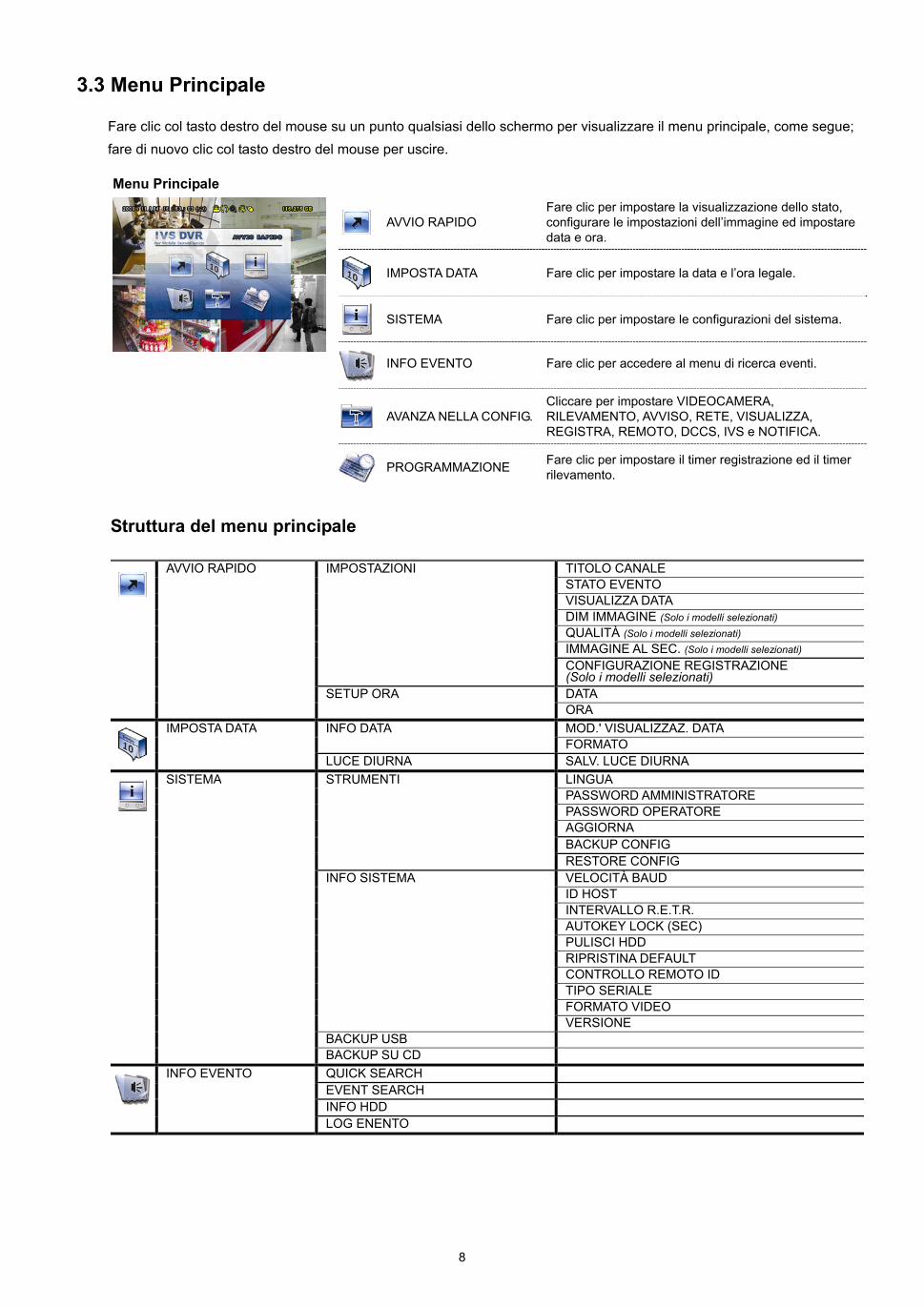
Fare clic col tasto destro del mouse su un punto qualsiasi dello schermo per visualizzare il menu principale, come segue; fare di nuovo clic col tasto destro del mouse per uscire.
Menu Principale
AVVIO RAPIDO Fare clic per impostare la visualizzazione dello stato, configurare le impostazioni dell’immagine ed impostare data e ora.
IMPOSTA DATA Fare clic per impostare la data e l’ora legale.
SISTEMA Fare clic per impostare le configurazioni del sistema.
INFO EVENTO Fare clic per accedere al menu di ricerca eventi.
AVANZA NELLA CONFIG.Cliccare per impostare VIDEOCAMERA, RILEVAMENTO, AVVISO, RETE, VISUALIZZA, REGISTRA, REMOTO, DCCS, IVS e NOTIFICA.
PROGRAMMAZIONE Fare clic per impostare il timer registrazione ed il timer
rilevamento.
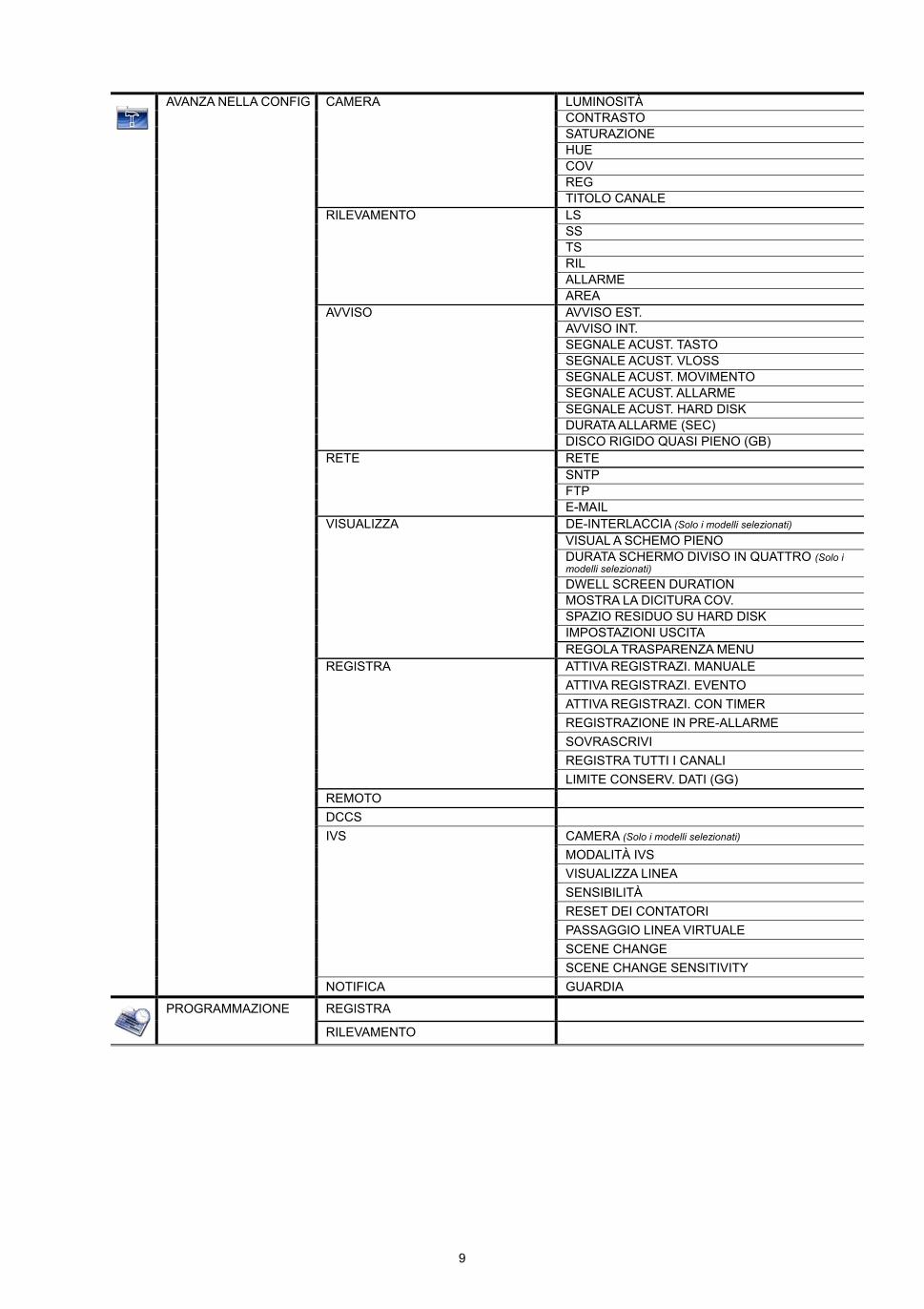
Struttura del menu principale
AVVIO RAPIDO IMPOSTAZIONI TITOLO CANALE STATO EVENTO VISUALIZZA DATA DIM IMMAGINE (Solo i modelli selezionati) QUALITÀ (Solo i modelli selezionati) IMMAGINE AL SEC. (Solo i modelli selezionati)
CONFIGURAZIONE REGISTRAZIONE (Solo i modelli selezionati)
SETUP ORA DATA
ORA IMPOSTA DATA INFO DATA MOD.' VISUALIZZAZ. DATA FORMATO
LUCE DIURNA SALV. LUCE DIURNA SISTEMA STRUMENTI LINGUA PASSWORD AMMINISTRATORE PASSWORD OPERATORE AGGIORNA BACKUP CONFIG RESTORE CONFIG INFO SISTEMA VELOCITÀ BAUD ID HOST INTERVALLO R.E.T.R. AUTOKEY LOCK (SEC) PULISCI HDD RIPRISTINA DEFAULT CONTROLLO REMOTO ID TIPO SERIALE FORMATO VIDEO VERSIONE BACKUP USB
BACKUP SU CD INFO EVENTO QUICK SEARCH EVENT SEARCH INFO HDD
LOG ENENTO
9
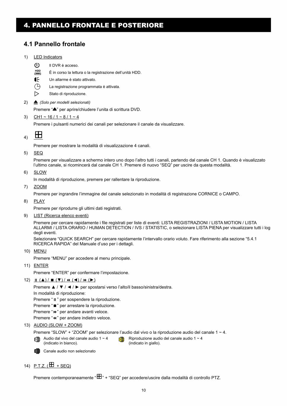
CAMERA LUMINOSITÀAVANZA NELLA CONFIG CONTRASTO
SATURAZIONE HUE COV REG TITOLO CANALE RILEVAMENTO LS SS TS RIL ALLARME AREA AVVISO AVVISO EST. AVVISO INT. SEGNALE ACUST. TASTO SEGNALE ACUST. VLOSS SEGNALE ACUST. MOVIMENTO SEGNALE ACUST. ALLARME SEGNALE ACUST. HARD DISK DURATA ALLARME (SEC) DISCO RIGIDO QUASI PIENO (GB) RETE RETE SNTP FTP E-MAIL VISUALIZZA DE-INTERLACCIA (Solo i modelli selezionati) VISUAL A SCHEMO PIENO
DURATA SCHERMO DIVISO IN QUATTRO (Solo i modelli selezionati)
DWELL SCREEN DURATION MOSTRA LA DICITURA COV. SPAZIO RESIDUO SU HARD DISK IMPOSTAZIONI USCITA
REGOLA TRASPARENZA MENU REGISTRA ATTIVA REGISTRAZI. MANUALE ATTIVA REGISTRAZI. EVENTO
ATTIVA REGISTRAZI. CON TIMER
REGISTRAZIONE IN PRE-ALLARME
SOVRASCRIVI REGISTRA TUTTI I CANALI LIMITE CONSERV. DATI (GG) REMOTO DCCS IVS CAMERA (Solo i modelli selezionati) MODALITÀ IVS VISUALIZZA LINEA SENSIBILITÀ RESET DEI CONTATORI PASSAGGIO LINEA VIRTUALE SCENE CHANGE
SCENE CHANGE SENSITIVITY
NOTIFICA GUARDIA
PROGRAMMAZIONE REGISTRA
RILEVAMENTO
10
4. PANNELLO FRONTALE E POSTERIORE
4.1 Pannello frontale
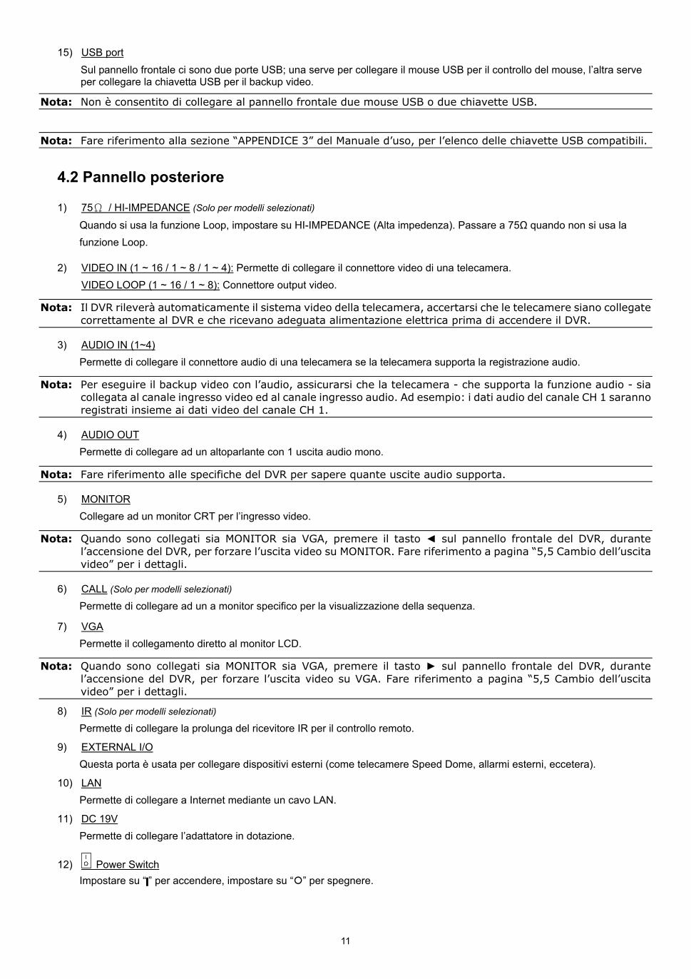
1) LED Indicators
Il DVR è acceso.
È in corso la lettura o la registrazione dell’unità HDD.
Un allarme è stato attivato.
La registrazione programmata è attivata.
Stato di riproduzione.
2) (Solo per modelli selezionati)
Premere “ ” per aprire/chiudere l’unita di scrittura DVD.
3) CH1 ~ 16 / 1 ~ 8 / 1 ~ 4
Premere i pulsanti numerici dei canali per selezionare il canale da visualizzare.
4)
Premere per mostrare la modalità di visualizzazione 4 canali.
5) SEQ
Premere per visualizzare a schermo intero uno dopo l’altro tutti i canali, partendo dal canale CH 1. Quando è visualizzato l’ultimo canale, si ricomincerà dal canale CH 1. Premere di nuovo “SEQ” per uscire da questa modalità.
6) SLOW
In modalità di riproduzione, premere per rallentare la riproduzione.
7) ZOOM
Premere per ingrandire l’immagine del canale selezionato in modalità di registrazione CORNICE o CAMPO.
8) PLAY
Premere per riprodurre gli ultimi dati registrati.
9) LIST (Ricerca elenco eventi)
Premere per cercare rapidamente i file registrati per liste di eventi: LISTA REGISTRAZIONI / LISTA MOTION / LISTA ALLARMI / LISTA ORARIO / HUMAN DETECTION / IVS / STATISTIC, o selezionare LISTA PIENA per visualizzare tutti i log degli eventi. Selezionare “QUICK SEARCH” per cercare rapidamente l’intervallo orario voluto. Fare riferimento alla sezione “5.4.1 RICERCA RAPIDA” del Manuale d’uso per i dettagli.
10) MENU
Premere “MENU” per accedere al menu principale.
11) ENTER
Premere “ENTER” per confermare l’impostazione.
12) () / () / () / ()
Premere / / / per spostarsi verso l’alto/il basso/sinistra/destra. In modalità di riproduzione: Premere “ ” per sospendere la riproduzione. Premere “ ” per arrestare la riproduzione. Premere “ ” per andare avanti veloce. Premere “ ” per andare indietro veloce.
13) AUDIO (SLOW + ZOOM)
Premere “SLOW” + “ZOOM” per selezionare l’audio dal vivo o la riproduzione audio del canale 1 ~ 4.
Audio dal vivo del canale audio 1 ~ 4 (indicato in bianco).
Riproduzione audio del canale audio 1 ~ 4 (indicato in giallo).
Canale audio non selezionato
14) P.T.Z. ( + SEQ)
Premere contemporaneamente “ ” + “SEQ” per accedere/uscire dalla modalità di controllo PTZ.
11
15) USB port
Sul pannello frontale ci sono due porte USB; una serve per collegare il mouse USB per il controllo del mouse, l’altra serve per collegare la chiavetta USB per il backup video.
Nota: Non è consentito di collegare al pannello frontale due mouse USB o due chiavette USB.
Nota: Fare riferimento alla sezione “APPENDICE 3” del Manuale d’uso, per l’elenco delle chiavette USB compatibili.
4.2 Pannello posteriore
1) 75Ω / HI-IMPEDANCE (Solo per modelli selezionati)
Quando si usa la funzione Loop, impostare su HI-IMPEDANCE (Alta impedenza). Passare a 75Ω quando non si usa la funzione Loop.
2) VIDEO IN (1 ~ 16 / 1 ~ 8 / 1 ~ 4): Permette di collegare il connettore video di una telecamera. VIDEO LOOP (1 ~ 16 / 1 ~ 8): Connettore output video.
Nota: Il DVR rileverà automaticamente il sistema video della telecamera, accertarsi che le telecamere siano collegate correttamente al DVR e che ricevano adeguata alimentazione elettrica prima di accendere il DVR.
3) AUDIO IN (1~4) Permette di collegare il connettore audio di una telecamera se la telecamera supporta la registrazione audio.
Nota: Per eseguire il backup video con l’audio, assicurarsi che la telecamera - che supporta la funzione audio - sia collegata al canale ingresso video ed al canale ingresso audio. Ad esempio: i dati audio del canale CH 1 saranno registrati insieme ai dati video del canale CH 1.
4) AUDIO OUT Permette di collegare ad un altoparlante con 1 uscita audio mono.
Nota: Fare riferimento alle specifiche del DVR per sapere quante uscite audio supporta.
5) MONITOR Collegare ad un monitor CRT per l’ingresso video.
Nota: Quando sono collegati sia MONITOR sia VGA, premere il tasto sul pannello frontale del DVR, durante l’accensione del DVR, per forzare l’uscita video su MONITOR. Fare riferimento a pagina “5,5 Cambio dell’uscita video” per i dettagli.
6) CALL (Solo per modelli selezionati) Permette di collegare ad un a monitor specifico per la visualizzazione della sequenza.
7) VGA Permette il collegamento diretto al monitor LCD.
Nota: Quando sono collegati sia MONITOR sia VGA, premere il tasto sul pannello frontale del DVR, durante l’accensione del DVR, per forzare l’uscita video su VGA. Fare riferimento a pagina “5,5 Cambio dell’uscita video” per i dettagli.
8) IR (Solo per modelli selezionati) Permette di collegare la prolunga del ricevitore IR per il controllo remoto.
9) EXTERNAL I/O Questa porta è usata per collegare dispositivi esterni (come telecamere Speed Dome, allarmi esterni, eccetera).
10) LAN Permette di collegare a Internet mediante un cavo LAN.
11) DC 19V Permette di collegare l’adattatore in dotazione.
12) Power Switch Impostare su “ ” per accendere, impostare su “ ” per spegnere.
12
5. OPERAZIONI DI BASE
5.1 Pagina dal vivo
Icona Funzione Icona Funzione Icona Funzione
Canale audio dal vivo (1 ~ 4) Canale audio di riproduzione (1 ~ 4) Canale audio disattivo
Zoom digitale attivo Zoom digitale disattivo Timer registrazione
Rete disconnessa Internet connesso LAN connessa
Mouse USB collegato Chiavetta/dispositivo USB collegato
Nessun dispositivo USB collegato
Blocco tasti Modalità PTZ attiva Sovrascrittura HDD
Amministratore Operatore Sequenza
Registrazione Evento allarme Evento movimento
Evento recinto virtuale. Evento passaggio unidirezionale Evento cambio di scena
Evento rilevamento presenza umana. Conteggio Flussi attivo Smart zoom
5.2 Icona di registrazione
1) Registrazione manuale
Per impostazione predefinita la registrazione manuale è attiva ( ) quando il DVR è acceso ed è installata una unità HDD.
2) Registrazione eventi
Le incone degli eventi, / / / / / , visualizzano sullo schermo quando si verificano i rispettivi eventi e la relativa funzione di registrazione è attiva.
3) Registrazione a tempo
Quando la registrazione a tempo è attiva, sullo schermo è visualizzata l’icona “ ”.
4) Sovrascrivi HDD
Per impostazione predefinita la funzione di sovrascrittura dell’unità HDD è attiva e sullo schermo è visualizzata l’icona “ ”.
5.3 Riproduzione
Fare clic su “ ” , nella barra del menu rapido, per visualizzare il pannello di controllo della riproduzione; fare clic su per riprodurre l’ultima sequenza video registrata, oppure fare clic su per accedere all'elenco di ricerca.
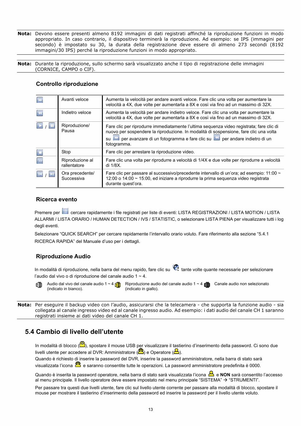
13
Nota: Devono essere presenti almeno 8192 immagini di dati registrati affinché la riproduzione funzioni in modo appropriato. In caso contrario, il dispositivo terminerà la riproduzione. Ad esempio: se IPS (immagini per secondo) è impostato su 30, la durata della registrazione deve essere di almeno 273 secondi (8192 immagini/30 IPS) perché la riproduzione funzioni in modo appropriato.
Nota: Durante la riproduzione, sullo schermo sarà visualizzato anche il tipo di registrazione delle immagini (CORNICE, CAMPO o CIF).
Controllo riproduzione
Avanti veloce Aumenta la velocità per andare avanti veloce. Fare clic una volta per aumentare la velocità a 4X, due volte per aumentarla a 8X e così via fino ad un massimo di 32X.
Indietro veloce Aumenta la velocità per andare indietro veloce. Fare clic una volta per aumentare la velocità a 4X, due volte per aumentarla a 8X e così via fino ad un massimo di 32X.
/ Riproduzione/ Pausa
Fare clic per riprodurre immediatamente l’ultima sequenza video registrata; fare clic di nuovo per sospendere la riproduzione. In modalità di sospensione, fare clic una volta su per avanzare di un fotogramma e fare clic su per andare indietro di un fotogramma.
Stop Fare clic per arrestare la riproduzione video.
Riproduzione al rallentatore
Fare clic una volta per riprodurre a velocità di 1/4X e due volte per riprodurre a velocità di 1/8X.
/ Ora precedente/ Successiva
Fare clic per passare al successivo/precedente intervallo di un’ora; ad esempio: 11:00 ~ 12:00 o 14:00 ~ 15:00, ed iniziare a riprodurre la prima sequenza video registrata durante quest’ora.
Ricerca evento
Premere per cercare rapidamente i file registrati per liste di eventi: LISTA REGISTRAZIONI / LISTA MOTION / LISTA ALLARMI / LISTA ORARIO / HUMAN DETECTION / IVS / STATISTIC, o selezionare LISTA PIENA per visualizzare tutti i log degli eventi.
Selezionare “QUICK SEARCH” per cercare rapidamente l’intervallo orario voluto. Fare riferimento alla sezione “5.4.1 RICERCA RAPIDA” del Manuale d’uso per i dettagli.
Riproduzione Audio
In modalità di riproduzione, nella barra del menu rapido, fare clic su tante volte quante necessarie per selezionare l’audio dal vivo o di riproduzione del canale audio 1 ~ 4.
Audio dal vivo del canale audio 1 ~ 4 (indicato in bianco).
Riproduzione audio del canale audio 1 ~ 4 (indicato in giallo).
Canale audio non selezionato
Nota: Per eseguire il backup video con l’audio, assicurarsi che la telecamera - che supporta la funzione audio - sia collegata al canale ingresso video ed al canale ingresso audio. Ad esempio: i dati audio del canale CH 1 saranno registrati insieme ai dati video del canale CH 1.
5.4 Cambio di livello dell’utente
In modalità di blocco ( ), spostare il mouse USB per visualizzare il tastierino d’inserimento della password. Ci sono due livelli utente per accedere al DVR: Amministratore ( ) e Operatore ( ). Quando è richiesto di inserire la password del DVR, inserire la password amministratore, nella barra di stato sarà visualizzata l’icona e saranno consentite tutte le operazioni. La password amministratore predefinita è 0000.
Quando è inserita la password operatore, nella barra di stato sarà visualizzata l’icona e NON sarà consentito l’accesso al menu principale. Il livello operatore deve essere impostato nel menu principale “SISTEMA” “STRUMENTI”. Per passare tra questi due livelli utente, fare clic sul livello utente corrente per passare alla modalità di blocco, spostare il mouse per mostrare il tastierino d’inserimento della password ed inserire la password per il livello utente voluto.
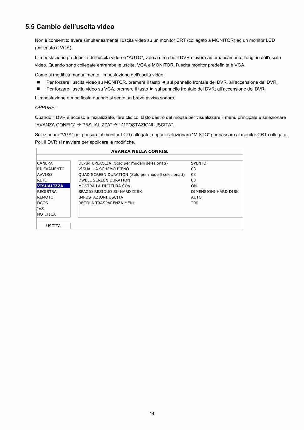
14
5.5 Cambio dell’uscita video
Non è consentito avere simultaneamente l’uscita video su un monitor CRT (collegato a MONITOR) ed un monitor LCD (collegato a VGA).
L’impostazione predefinita dell’uscita video è “AUTO”, vale a dire che il DVR rileverà automaticamente l’origine dell’uscita video. Quando sono collegate entrambe le uscite, VGA e MONITOR, l’uscita monitor predefinita è VGA.
Come si modifica manualmente l’impostazione dell’uscita video: Per forzare l’uscita video su MONITOR, premere il tasto sul pannello frontale del DVR, all’accensione del DVR. Per forzare l’uscita video su VGA, premere il tasto sul pannello frontale del DVR, all’accensione del DVR.
L’impostazione è modificata quando si sente un breve avviso sonoro.
OPPURE:
Quando il DVR è acceso e inizializzato, fare clic col tasto destro del mouse per visualizzare il menu principale e selezionare “AVANZA CONFIG” “VISUALIZZA” “IMPOSTAZIONI USCITA”.
Selezionare “VGA” per passare al monitor LCD collegato, oppure selezionare “MISTO” per passare al monitor CRT collegato. Poi, il DVR si riavvierà per applicare le modifiche.
AVANZA NELLA CONFIG.
CANERA DE-INTERLACCIA (Solo per modelli selezionati) SPENTO
RILEVAMENTO VISUAL. A SCHEMO PIENO 03
AVVISO QUAD SCREEN DURATION (Solo per modelli selezionati) 03
RETE DWELL SCREEN DURATION 03 VISUALIZZA MOSTRA LA DICITURA COV. ON
REGISTRA SPAZIO RESIDUO SU HARD DISK DIMENSIONI HARD DISK
REMOTO IMPOSTAZIONI USCITA AUTO DCCS REGOLA TRASPARENZA MENU 200
IVS NOTIFICA
USCITA
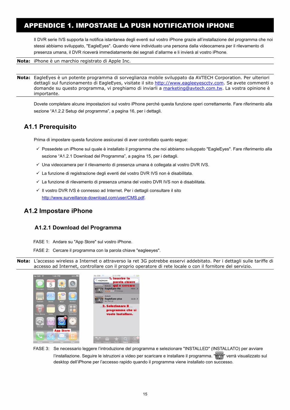
15
APPENDICE 1. IMPOSTARE LA PUSH NOTIFICATION IPHONE
Il DVR serie IVS supporta la notifica istantanea degli eventi sul vostro iPhone grazie all’installazione del programma che noi stessi abbiamo sviluppato, "EagleEyes". Quando viene individuato una persona dalla videocamera per il rilevamento di presenza umana, il DVR riceverà immediatamente dei segnali d’allarme e li invierà al vostro iPhone.
Nota: iPhone è un marchio registrato di Apple Inc.
Nota: EagleEyes è un potente programma di sorveglianza mobile sviluppato da AVTECH Corporation. Per ulteriori dettagli sul funzionamento di EagleEyes, visitate il sito http://www.eagleeyescctv.com. Se avete commenti o domande su questo programma, vi preghiamo di inviarli a [email protected]. La vostra opinione è importante.
Dovete completare alcune impostazioni sul vostro iPhone perché questa funzione operi correttamente. Fare riferimento alla sezione “A1.2.2 Setup del programma”, a pagina 16, per i dettagli.
A1.1 Prerequisito
Prima di impostare questa funzione assicurasi di aver controllato quanto segue:
Possedete un iPhone sul quale è installato il programma che noi abbiamo sviluppato "EagleEyes". Fare riferimento alla sezione “A1.2.1 Download del Programma”, a pagina 15, per i dettagli.
Una videocamera per il rilevamento di presenza umana è collegata al vostro DVR IVS.
La funzione di registrazione degli eventi del vostro DVR IVS non è disabilitata.
La funzione di rilevamento di presenza umana del vostro DVR IVS non è disabilitata.
Il vostro DVR IVS è connesso ad Internet. Per i dettagli consultare il sito http://www.surveillance-download.com/user/CMS.pdf.
A1.2 Impostare iPhone
A1.2.1 Download del Programma
FASE 1: Andare su "App Store" sul vostro iPhone.
FASE 2: Cercare il programma con la parola chiave "eagleeyes".
Nota: L’accesso wireless a Internet o attraverso la ret 3G potrebbe esservi addebitato. Per i dettagli sulle tariffe di accesso ad Internet, controllare con il proprio operatore di rete locale o con il fornitore del servizio.
FASE 3: Se necessario leggere l’introduzione del programma e selezionare "INSTALLED" (INSTALLATO) per avviare
l’installazione. Seguire le istruzioni a video per scaricare e installare il programma. " " verrà visualizzato sul desktop dell’iPhone per l’accesso rapido quando il programma viene installato con successo.
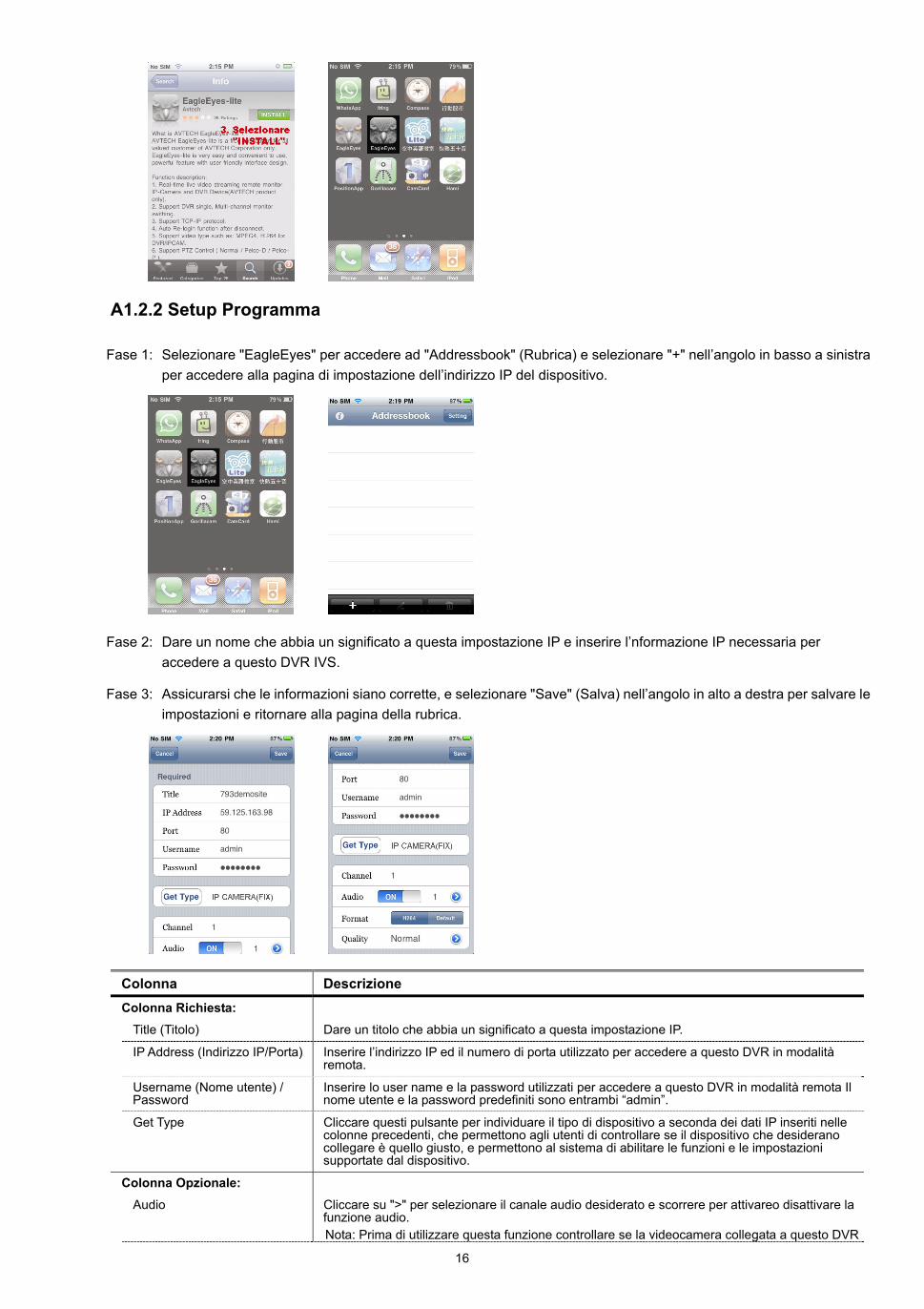
16
A1.2.2 Setup Programma
Fase 1: Selezionare "EagleEyes" per accedere ad "Addressbook" (Rubrica) e selezionare "+" nell’angolo in basso a sinistra per accedere alla pagina di impostazione dell’indirizzo IP del dispositivo.
Fase 2: Dare un nome che abbia un significato a questa impostazione IP e inserire l’nformazione IP necessaria per accedere a questo DVR IVS.
Fase 3: Assicurarsi che le informazioni siano corrette, e selezionare "Save" (Salva) nell’angolo in alto a destra per salvare le impostazioni e ritornare alla pagina della rubrica.
Colonna Descrizione Colonna Richiesta:
Title (Titolo) Dare un titolo che abbia un significato a questa impostazione IP.
IP Address (Indirizzo IP/Porta) Inserire l’indirizzo IP ed il numero di porta utilizzato per accedere a questo DVR in modalità remota.
Username (Nome utente) / Password
Inserire lo user name e la password utilizzati per accedere a questo DVR in modalità remota Il nome utente e la password predefiniti sono entrambi “admin”.
Get Type Cliccare questi pulsante per individuare il tipo di dispositivo a seconda dei dati IP inseriti nelle colonne precedenti, che permettono agli utenti di controllare se il dispositivo che desiderano collegare è quello giusto, e permettono al sistema di abilitare le funzioni e le impostazioni supportate dal dispositivo.
Colonna Opzionale:
Audio Cliccare su ">" per selezionare il canale audio desiderato e scorrere per attivareo disattivare la funzione audio. Nota: Prima di utilizzare questa funzione controllare se la videocamera collegata a questo DVR
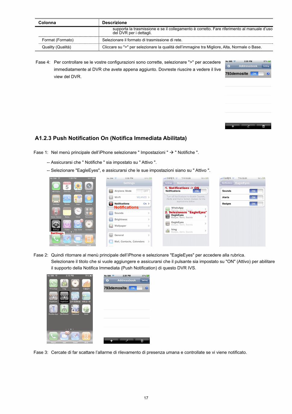
17
Colonna Descrizione supporta la trasmissione e se il collegamento è corretto. Fare riferimento al manuale d’uso del DVR per i dettagli.
Format (Formato) Selezionare il formato di trasmissione di rete.
Quality (Qualità) Cliccare su ">" per selezionare la qualità dell’immagine tra Migliore, Alta, Normale o Base.
Fase 4: Per controllare se le vostre configurazioni sono corrette, selezionare ">" per accedere
immediatamente al DVR che avete appena aggiunto. Dovreste riuscire a vedere il live view del DVR.
A1.2.3 Push Notification On (Notifica Immediata Abilitata)
Fase 1: Nel menù principale dell’iPhone selezionare " Impostazioni " " Notifiche ".
-- Assicurarsi che " Notifiche " sia impostato su " Attivo ".
-- Selezionare "EagleEyes", e assicurarsi che le sue impostazioni siano su " Attivo ".
Fase 2: Quindi ritornare al menù principale dell’iPhone e selezionare "EagleEyes" per accedere alla rubrica. Selezionare il titolo che si vuole aggiungere e assicurarsi che il pulsante sia impostato su "ON" (Attivo) per abilitare il supporto della Notifica Immediata (Push Notification) di questo DVR IVS.
Fase 3: Cercate di far scattare l’allarme di rilevamento di presenza umana e controllate se vi viene notificato.
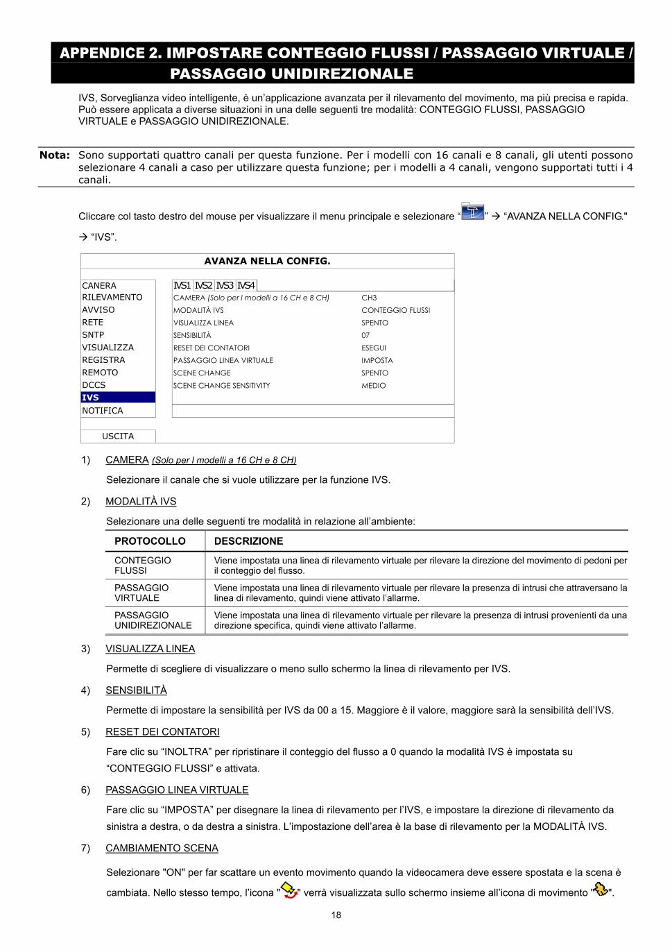
18
APPENDICE 2. IMPOSTARE CONTEGGIO FLUSSI / PASSAGGIO VIRTUALE / PASSAGGIO UNIDIREZIONALE
IVS, Sorveglianza video intelligente, è un’applicazione avanzata per il rilevamento del movimento, ma più precisa e rapida. Può essere applicata a diverse situazioni in una delle seguenti tre modalità: CONTEGGIO FLUSSI, PASSAGGIO VIRTUALE e PASSAGGIO UNIDIREZIONALE.
Nota: Sono supportati quattro canali per questa funzione. Per i modelli con 16 canali e 8 canali, gli utenti possono selezionare 4 canali a caso per utilizzare questa funzione; per i modelli a 4 canali, vengono supportati tutti i 4 canali.
Cliccare col tasto destro del mouse per visualizzare il menu principale e selezionare “ ” “AVANZA NELLA CONFIG."
“IVS”.
AVANZA NELLA CONFIG.
CANERA IVS1 IVS2 IVS3 IVS4 RILEVAMENTO CAMERA (Solo per l modelli a 16 CH e 8 CH) CH3 AVVISO MODALITÀ IVS CONTEGGIO FLUSSI RETE VISUALIZZA LINEA SPENTO SNTP SENSIBILITÀ 07 VISUALIZZA RESET DEI CONTATORI ESEGUI REGISTRA PASSAGGIO LINEA VIRTUALE IMPOSTA REMOTO SCENE CHANGE SPENTO DCCS SCENE CHANGE SENSITIVITY MEDIO IVS
NOTIFICA
USCITA
1) CAMERA (Solo per l modelli a 16 CH e 8 CH)
Selezionare il canale che si vuole utilizzare per la funzione IVS.
2) MODALITÀ IVS
Selezionare una delle seguenti tre modalità in relazione all’ambiente:
PROTOCOLLO DESCRIZIONE
CONTEGGIO FLUSSI
Viene impostata una linea di rilevamento virtuale per rilevare la direzione del movimento di pedoni per il conteggio del flusso.
PASSAGGIO VIRTUALE
Viene impostata una linea di rilevamento virtuale per rilevare la presenza di intrusi che attraversano la linea di rilevamento, quindi viene attivato l’allarme.
PASSAGGIO UNIDIREZIONALE
Viene impostata una linea di rilevamento virtuale per rilevare la presenza di intrusi provenienti da una direzione specifica, quindi viene attivato l’allarme.
3) VISUALIZZA LINEA
Permette di scegliere di visualizzare o meno sullo schermo la linea di rilevamento per IVS.
4) SENSIBILITÀ
Permette di impostare la sensibilità per IVS da 00 a 15. Maggiore è il valore, maggiore sarà la sensibilità dell’IVS.
5) RESET DEI CONTATORI
Fare clic su “INOLTRA” per ripristinare il conteggio del flusso a 0 quando la modalità IVS è impostata su “CONTEGGIO FLUSSI” e attivata.
6) PASSAGGIO LINEA VIRTUALE
Fare clic su “IMPOSTA” per disegnare la linea di rilevamento per l’IVS, e impostare la direzione di rilevamento da sinistra a destra, o da destra a sinistra. L’impostazione dell’area è la base di rilevamento per la MODALITÀ IVS.
7) CAMBIAMENTO SCENA
Selezionare "ON" per far scattare un evento movimento quando la videocamera deve essere spostata e la scena è
cambiata. Nello stesso tempo, l’icona " " verrà visualizzata sullo schermo insieme all’icona di movimento " ".
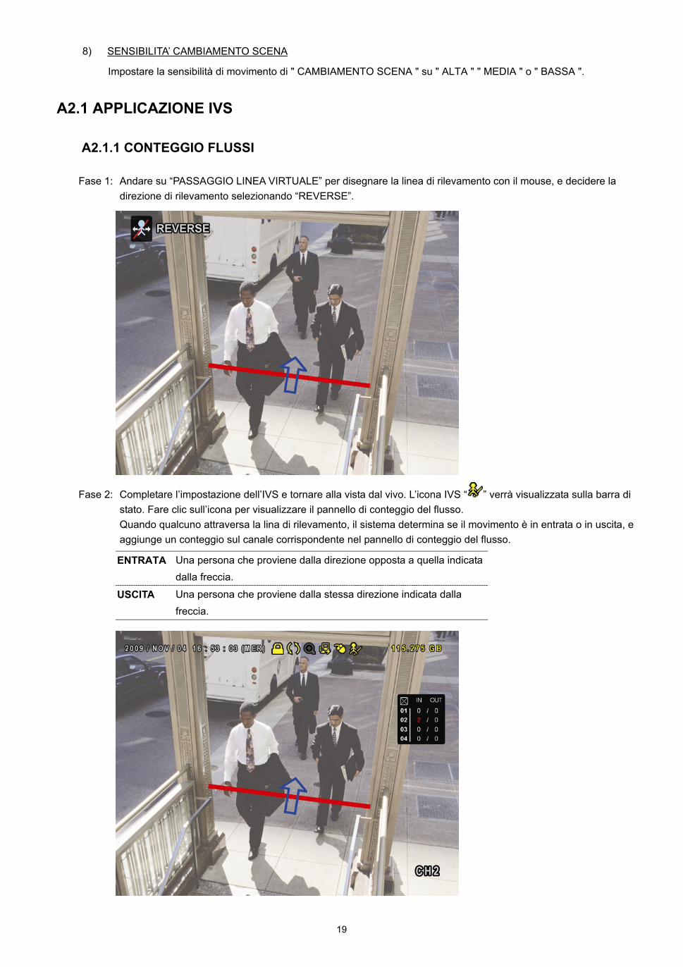
19
8) SENSIBILITA’ CAMBIAMENTO SCENA
Impostare la sensibilità di movimento di " CAMBIAMENTO SCENA " su " ALTA " " MEDIA " o " BASSA ".
A2.1 APPLICAZIONE IVS
A2.1.1 CONTEGGIO FLUSSI
Fase 1: Andare su “PASSAGGIO LINEA VIRTUALE” per disegnare la linea di rilevamento con il mouse, e decidere la direzione di rilevamento selezionando “REVERSE”.
Fase 2: Completare l’impostazione dell’IVS e tornare alla vista dal vivo. L’icona IVS “ ” verrà visualizzata sulla barra di stato. Fare clic sull’icona per visualizzare il pannello di conteggio del flusso. Quando qualcuno attraversa la lina di rilevamento, il sistema determina se il movimento è in entrata o in uscita, e aggiunge un conteggio sul canale corrispondente nel pannello di conteggio del flusso.
ENTRATA Una persona che proviene dalla direzione opposta a quella indicata dalla freccia.
USCITA Una persona che proviene dalla stessa direzione indicata dalla freccia.
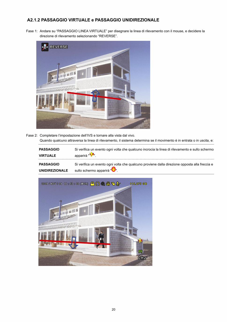
20
A2.1.2 PASSAGGIO VIRTUALE e PASSAGGIO UNIDIREZIONALE
Fase 1: Andare su “PASSAGGIO LINEA VIRTUALE” per disegnare la linea di rilevamento con il mouse, e decidere la direzione di rilevamento selezionando “REVERSE”.
Fase 2: Completare l’impostazione dell’IVS e tornare alla vista dal vivo. Quando qualcuno attraversa la linea di rilevamento, il sistema determina se il movimento è in entrata o in uscita, e:
PASSAGGIO
VIRTUALE
Si verifica un evento ogni volta che qualcuno incrocia la linea di rilevamento e sullo schermo
apparirà " ".
PASSAGGIO
UNIDIREZIONALE
Si verifica un evento ogni volta che qualcuno proviene dalla direzione opposta alla freccia e
sullo schermo apparirà " ".
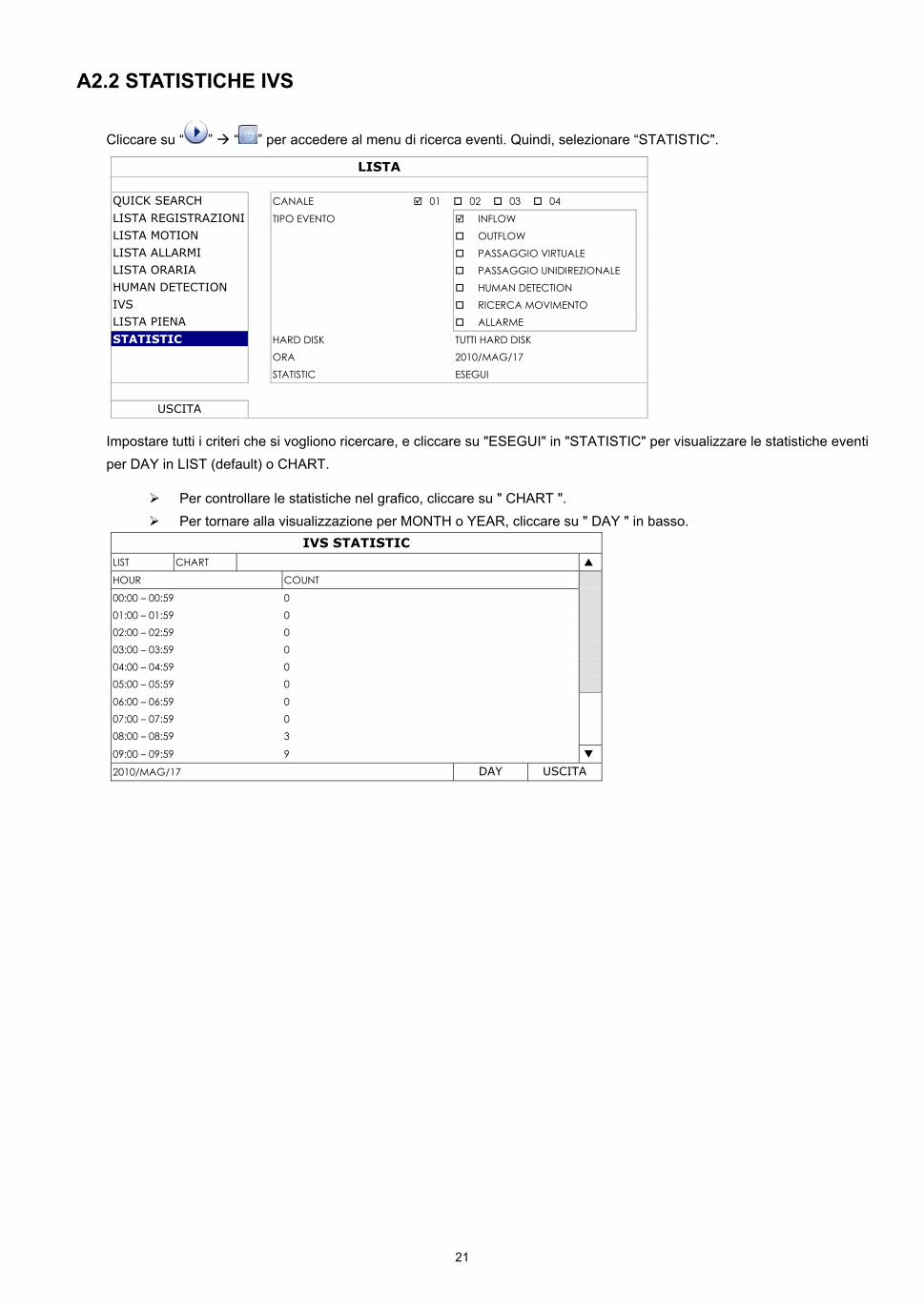
21
A2.2 STATISTICHE IVS
Cliccare su “ ” “ ” per accedere al menu di ricerca eventi. Quindi, selezionare “STATISTIC".
LISTA
QUICK SEARCH CANALE 01 02 03 04
LISTA REGISTRAZIONI TIPO EVENTO INFLOW LISTA MOTION OUTFLOW LISTA ALLARMI PASSAGGIO VIRTUALE LISTA ORARIA PASSAGGIO UNIDIREZIONALE HUMAN DETECTION HUMAN DETECTION IVS RICERCA MOVIMENTO LISTA PIENA ALLARME
STATISTIC HARD DISK TUTTI HARD DISK ORA 2010/MAG/17 STATISTIC ESEGUI
USCITA
Impostare tutti i criteri che si vogliono ricercare, e cliccare su "ESEGUI" in "STATISTIC" per visualizzare le statistiche eventi per DAY in LIST (default) o CHART.
Per controllare le statistiche nel grafico, cliccare su " CHART ". Per tornare alla visualizzazione per MONTH o YEAR, cliccare su " DAY " in basso.
IVS STATISTIC LIST CHART
HOUR COUNT
00:00 – 00:59 0 01:00 – 01:59 0 02:00 – 02:59 0 03:00 – 03:59 0 04:00 – 04:59 0 05:00 – 05:59 0
06:00 – 06:59 0 07:00 – 07:59 0 08:00 – 08:59 3
09:00 – 09:59 9
2010/MAG/17 DAY USCITA