Embed Size (px)
Citation preview
6
AVC Using a Backstepping Design Technique
R. Ferreiro García, F. Fraguela Diaz, A. De Miguel Catoira University of A Coruna
Spain
1. Introduction
This chapter deals with the vibration attenuation or vibration suppression by means of feedback control techniques applied to decrease the dynamic response of a rotor assumed as active magnetic dynamic damping which is common in rotating machinery supported by active magnetic bearings. Position control systems applied on active magnetic bearings are using sometimes nonlinear robust control techniques. Backstepping control algorithms have been successfully applied to control active magnetic bearings in recent industrial applications. Consequently, when such an algorithm is being applied to control the radial shaft position, active vibration control should be performed taking advantage of the use of the same control algorithm. In the proposed methodology it is applied the Backstepping algorithm in cascade with a master conventional PID controller. The main functions of the cascade strategy are summarized as, desired radial shaft trajectory and radial position generation, rotor stabilization and vibration attenuation. Backstepping methodology provides a rather straightforward way to design the slave or cascade controller suitable for an unstable nonlinear system such as a magnetic bearing. Stabilization of the closed-loop system is achieved by incorporating appropriate Lyapunov functions which are inherent to the Backstepping algorithm. The global asymptotic stability is ensured when the derivative of the Lyapunov function is rendered negative definite by the control law. The closed loop damping or vibration attenuation is achieved according requirements by on-line determining and selecting the appropriate gains and parameters for the implemented control strategy as function of the fundamental vibration characteristics. The aim to continue with research activities on this technologic field after more then three decades of intensive work, obeys to the fact that some modern machines require the characteristics and advantages of applying such technology (Gerhard Schweitzer, Eric H. Maslen Editors, 2009). The main characteristics of AMB based machines where the rotor is supported by radial active magnetic bearings are summarized as follows: The unbalance compensation.- The most relevant characteristic of an AMB deals with the active compensation of shaft disturbances, such vibration due to residual unbalance which can be effectively measured and identified by the AMB control system. The signal is used to either generate counteracting and compensating bearing forces or to shift the rotor axis in such away that the rotor is rotating force-free. The positioning precision.- The radial precision with which the position of the rotor can be controlled, is mainly determined by the precision or quality of the measurement signal within the control loop. Conventional inductive sensors, (eddy current based sensors) for example, have a measurement resolution of about 1/100 to 1/1000 of a millimetre.
Source: Vibration Control, Book edited by: Dr. Mickaël Lallart, ISBN 978-953-307-117-6, pp. 380, September 2010, Sciyo, Croatia, downloaded from SCIYO.COM
www.intechopen.com
Vibration Control
160
Diagnostics.- On the basis of acquired data inherent to the position and vibration suppression control, diagnostics are readily performed, as the states and dynamic condition of the rotor are measured for the operation of the AMB anyway, and this information can be used to monitor and check operating conditions and performance. Even active diagnostics are feasible, by using the AMB as actuators in model analysis mode for generating well defined test signals simultaneously with their bearing function. The results of the design technique are evaluated on a vertical test rig where real-time data is analysed and compared with conventional control results.
1.1 The backstepping based AVC background
Active vibration control (AVC) applied on rotating machinery continues being after more than three decades of intensive research an area of primary interest (Tao Yang et al., 2009). AVC applied on active magnetic bearings (AMB) continues also being an important and active research area motivated by the demand of efficiency in the industrial production system. It deals essentially with nonlinear systems and nonlinear control theory, where among a vast range of applied nonlinear control strategies and algorithms, backstepping theory can definitely contribute positively to AVC of AMB. Nonlinear control theory has been the subject of very strong development during the last two decades (Hassan K. Khalil, 2002), (Krstic, M., I. Kanellakopoulos, & P. Kokotovic, 1995). The existing problems with regard to the control of unstable nonlinear systems, has been the amount of difficulties encountered in achieving a systematic way to ensure closed loop stability (Krstic M., & H. Deng, 1998). The tools developed in this area suddenly made the design and implementation of controllers to be applied on nonlinear systems, significantly more structured and rather straightforward with the incorporation of Backstepping theory. One of the concepts, which are well known today to overcome some of the mentioned difficulties with nonlinear control algorithms, is Backstepping theory. Some interesting applications to AVC have recently been reported. Hence, in (Guang Lia & Amir Khajepour, 2005) a robust controller is developed to regulate both flexural vibrations and rigid body motion of a hydraulically driven flexible arm. The proposed controller combines backstepping, sliding mode, and pole placement techniques to arrive at a controller capable of dealing with a nonlinear system with uncertainties. The sliding mode technique is used to achieve an asymptotic joint angle and vibration regulation. (Qinglei Hu, 2009) proposes an angular velocity bounded robust adaptive control design for attitude maneuver and vibration reduction in the presence of external disturbances and uncertainties in the inertia matrix. (V. Mañosa, F. Ikhouane, J. Rodellar, 2005) presents a backstepping-based adaptive control designed for a class of one degree-of-freedom uncertain non-linear systems. The efficiency of the approach has been tested by numerical simulations on Duffing oscillators and systems with non-linear and hysteretic stiffness under external loads. In (Francesc Pozo et al., 2006) it is used an adaptive backstepping approach for vibration control of a hybrid seismic control system. (In Tao Yang et al., 2009), a backstepping control approach is applied to solve the active vibration isolation problem using a Stewart platform. They demonstrated that the controller can effectively attenuate low frequency vibrations in six degrees of freedom achieving satisfactory vibration isolation performance. The work presented in this chapter is focused on the successfully application of the Backstepping theory on a typical unstable nonlinear system such as the active vibration control (vibration attenuation but not vibration suppression) on AMB’s.
www.intechopen.com
AVC Using a Backstepping Design Technique
161
1.2 The backstepping background
The backstepping algorithm can be applied on control problems where a strict feedback state space model of the plant or process is available. The application presented in this chapter is one of those nonlinear systems, which have been subject to intensive studies in order to find fully stabilizing controllers. The Backstepping theory provides a tool for the recursive design of the control law based on the Lyapunov theory for stabilizing the controlled system (Hassan K. Khalil, 2002) and (Krstic, M., I. Kanellakopoulos, & P. Kokotovic, 1995). Control systems have one main goal to achieve, and that is the stability of the controlled system. An important topic with regard to the stability of dynamical systems concerns to the stability of equilibrium points, which is verified by Lyapunov Stability and LaSalle-Yoshizawa theorems (LaSalle J. P., 1960), (LaSalle, J.P., 1966), (Sontag E. D., A, 1989), (Yoshizawa, T., 1968). The stability of nonlinear systems is verified by means of the following analytical background: Theorem 1 (LaSalle-Yoshizawa) Assuming the system
( ( ))x f x t=$ (1)
with the initial condition x(0), let x=0 be an equilibrium point for (1); let V(x) be a scalar, continuously differentiable function of the state x such that
• V(x) is positive definite • V(x) is radially unbounded
• ( ) ( ) ( ) ( )xV x V x f x W x= ≤ −$ , where W(x) is positive semi-definite
Then, all solutions of (1) satisfy
lim ( ( )) 0W x t
t
=→∞
Furthermore, if W(x) is positive definite, then the equilibrium x = 0 is globally uniformly asymptotically stable (GUAS). For proof, see (Hassan K. Khalil, 2002) and (Krstic, M., I. Kanellakopoulos, & P. Kokotovic, 1995) and (LaSalle J. P., 1960), (LaSalle, J.P., 1968), (Sontag E. D., A, 1989), (Sontag E.D., & Sussman, 1998), (Yoshizawa, T, 1966), (Yoshizawa, T., 1968).
Note that any equilibrium under investigation can be mapped to the origin by substituting x with z= x xe. Therefore, there is no loss of generality in standardizing results for the zero solution z ≡ 0. But demanding V$ to be negative definite, in order to claim stability, may not perform successfully. Now that it is stated the foundation of Lyapunov stability, the main question arising is how to find these functions. The theorems above do not provide any systematic method of finding these functions. In the case of electrical or mechanical systems there are natural Lyapunov function candidates like total energy functions. In other cases, it is basically a matter of trial and error. The Backstepping approach is so far the only systematic and recursive method for
constructing a Lyapunov function, along the design of the stabilizing control law. Yet, the
system must have a lower triangular structure in order to apply the method. Before we can
explore this state-of-the-art technique in control of nonlinear systems, it is convenient extend
the systems handled so far to those including a control input.
www.intechopen.com
Vibration Control
162
1.3 Control Lyapunov Functions (CLF)
Since an objective is to develop closed-loop systems with desirably stability properties, let us now add a control input to the considered system
( , ), , , (0,0) 0nx f x u x R u R f= ∈ ∈ =$ (2)
It is necessary to introduce an extension of the Lyapunov function concept, the CLF. Given
the stability results from the previous section, the objective is to find a control law ( )u xα=
such that the desired state of the closed-loop system ( , ( ))x f x xα=$ be Globally Asymptotic
Stable (GAS) equilibrium point. Once again it is considered the origin to be the goal state for
simplicity. It can be chosen a function V(x) as a Lyapunov candidate, and require that its
derivative along the solutions of (2) satisfy ( ) ( )V x W x≤ −$ , where W(x) is positive definite
function. Then closed-loop stability follows from Theorem (1). It is necessary therefore to
find ( )xα to guarantee that for all nx R∈ .
( ) ( ) ( , ( )) ( )V
V x x f x x W xx
α∂= ≤ −∂$ (3)
The pair V and W must be chosen carefully otherwise (4) will not be solvable. This motivates the following definition, which can be found in (Krstic, M., I. Kanellakopoulos, & P. Kokotovic, 1995). Definition 1.(CLF) A smooth positive definite and radially unbounded function V: Rn →R is a CLF if for(2) and every
x ≠ 0
( ) ( ) ( , ) 0 0xV x V x f x u x and for some u= < ∀ ≠$ (4)
The significance of this definition concerns to the fact that, the existence of a globally asymptotic stabilizing control law is equivalent to the existence of a CLF. If exists a CLF for the system, then it is certainly possible to find a globally stabilizing control law. The reverse is also true. This is known as Artestin’s theorem and can be found in (Sontag E. D., 1989). Now that the concept CLF is defined, it is necessary to move on and explore the Backstepping theory, which is the main tool we must deal with.
1.4 The backstepping algorithm
The main drawback of the CLF concept as a design tool is that for most nonlinear systems the proper CLF is not known. The task of finding an appropriate CLF may be complex as well as that of designing a stabilizing feedback law. The Backstepping procedure solves both problems simultaneously. The standard procedure can be found in (Hassan K. Khalil,2002), (Krstic, M., I. Kanellakopoulos, & P. Kokotovic, 1995). To spare the reader from the effort to understand the main ideas of Backstepping by a theorem, it helps more by starting from the description of the general procedure, which will clarify such concepts
1.5 General backstepping procedure
Given a SISO nonlinear, non-minimum phase process described under a street feedback state space model, and assuming Yr to be a tracking reference trajectory, the following sequence is to be performed under a systematic procedure according the generic following steps:
www.intechopen.com
AVC Using a Backstepping Design Technique
163
Step 1: Error step 1:
1 1rZ Y X= − (5a)
Lyapunov Function 1st step:
21 1
1
2V Z= (5b)
Derivative of V1:
1 1 1 1 2( )rV Z Z Z Y X= = −$$ $ (5c)
Stabilizing function 1st step:
1 2 1 1d rX Y P Zα = = −$ (5d)
with P1 >0 Step 2: Error step 2
2 2 2 2 1dZ X X X α= − = − (5e)
Lyapunov Function 2d step:
2 22 1 2
1 1
2 2V Z Z= + (5f)
With
1 1 2 1 1 2r rZ Y X Y X P Z Z= − = − = −$ $$ $ (5g)
erivative of V2:
22 1 1 2 1 2 1( )V P Z Z Z X α= − + −$ $ $ (5h)
2 22 1 1 2 1 1 1 2 3(1 ) rV P Z Z P Z P Z X Y⎡ ⎤= − − + + −⎣ ⎦$$$ (5i)
Stabilizing function 2d step:
22 3 1 1 1 2 2( 1) ( )d rX P Z P P Z Yα = = − − + + $$ (5j)
with P2 >0 Step i: Error step i
1i i id i iZ X X X α −= − = − (5k)
Lyapunov Function ith step:
2
1
1
2
i
i jj
V Z=
= ∑ (5l)
With
www.intechopen.com

Vibration Control
164
1 1 1 2i i i i iZ Z P Z Z− − − −= − −$ (5m)
Derivative of Vi:
1
21 1
1
i
i j j i i i ij
V P Z Z Z X α−− −=
⎡ ⎤= − + + −⎣ ⎦∑$ $ $ (5n)
Stabilizing function ith step:
1 1 1i i i i i iX PZ Zα α+ − −= = − − + $ (5o)
where Pi > 0, are positive constants. The corresponding notation is shown in figure 1, in which it is illustrated a generic process state space representation corrected with stabilizing functions by means of Backstepping procedure. In order to avoid static control errors for systems type 0, an integrator must be added in series with the plant model. Then, at the end of the design procedure, this integrator is moved from the plant model to the control equation (Hassan K. Khalil, 2002), (Krstic, M., I. Kanellakopoulos, & P. Kokotovic, 1995). An alternative to such generalized technique consists in adding a cascade Backstepping algorithm following the setpoint generated by a feedback conventional controller.
Fig. 1. General process representation stabilized by means of the Backstepping procedure
Assumption 1. Assuming the system
( ) ( ) , (0) 0,x f x g x u f= + =$ (6)
where x ∈ Rn is the state and u ∈ Rn is the control input, the there exists a continuous differentiable feedback control law
( ), (0) 0,u xα α= = (7)
and a smooth, positive definite, radially unbounded function V: Rn →R such that
( ) ( ) ( ) ( ) 0,V
f x g x x W x x Rx
α∂ + ≤ − ≤ ∀ ∈⎡ ⎤⎣ ⎦∂ (8)
where W: Rn→R is positive semi-definite.
∫ ∫ ∫ ∫ -X1
X’X’2X’i
α1 α2 αi
u
Y’r
X’i+ Z1 Z2 Z3 Z4
θi
: θ3
θ2
θ1
-Xi+1 -X2 -X3
www.intechopen.com

AVC Using a Backstepping Design Technique
165
By means of this assumption, the control (7) applied to the system (6) guarantees global boundedness of x(t). Let the system (6) be augmented by an integrator according the expression
( ) ( )x f x g x
u
ξξ= +=
$$ (9)
and suppose that satisfies the above assumption with ξ Є ˚ as its control variable.
Lemma 1
Being W(x) positive definite, then
21
( , ) ( ) ( )2
aV x V x xξ ξ α= + −⎡ ⎤⎣ ⎦ (10)
is a CLF for the complete system (9). That means, there exists a feedback control ( , )au xα ξ=
which renders ( , ) (0,0)x ξ = the GAS equilibrium of (9). Such control results in
( ( )) ( ) ( ) ( ), 0V
u c x f x g x g x cx x
αξ α ξ∂ ∂= − − + + −⎡ ⎤⎣ ⎦∂ ∂ B Z (11)
Up to now it has been introduced the methodology and tools to design a stabilizing control law and determine its stability properties. In the next section a brief description of active magnetic bearings is presented.
2. The AMB control environment
2.1 Background
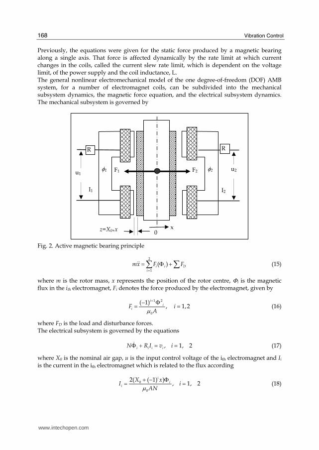
From a control viewpoint, an AMB is a nonlinear unstable process. The simplest model is represented with figure 2. The application of AMB’s is based upon the principle that an electromagnet will attract ferromagnetic material. A ferromagnetic rotor can thus be supported in a magnetic field generated in the bearing electromagnet stator, as shown in the figure 2. Since the natural tendency of the stator is to attract the rotor until it makes contact, some control action is required to modulate the magnetic field and maintain the rotor in the desired position. The most common type of control involves the feedback of shaft position. This information is then used by the control system to modulate the magnetic field through power amplifiers, so that the desired rotor position is maintained even under changing shaft load conditions. An active magnetic bearing system consists of electromagnet bearing actuators, position sensors, a control system and power amplifiers. The bearing actuators and sensors are located in the machine, while the control system and amplifiers are generally located remotely. A typical system consists of two radial bearings and a thrust bearing. Each radial bearing has a stator and sensor system mounted over a ferromagnetic rotor installed on the shaft. The rotor consists of a stack of lamination rings mounted on a sleeve that fits onto the shaft. Laminations are used to reduce eddy current losses and to improve the response of the bearing. The stator is made of a stack of lamination rings with poles on the internal diameter. Coils are wound around each pole so that the bearing is divided into four
www.intechopen.com
Vibration Control
166
quadrants. The coils in each quadrant are wound in series making each quadrant function as one electromagnet. Typically on horizontal machines, the quadrants are aligned 45 degrees from vertical. Opposing quadrants constitute an axis and therefore each radial bearing can be described by two axes. A set of sensors that measure shaft position are mounted as close to the bearing as possible. As the results shown along a couple of years indicate, digital control provides capabilities for adaptive control which can be used to greatly alleviate the unbalance vibration of rotating machinery. This is often the worst vibration problem encountered during operation. The source of this vibration is the discrepancy between the geometric axis of the rotor and its inertial axis. When the rotor is spinning, this imbalance results in a centrifugal force which causes synchronous vibration throughout the machine. This problem is managed on conventional machinery through mechanical balancing by means of the addition or removal of a small amount of mass from the shaft to reduce the residual imbalance. Rotor balancing in the field, unfortunately, is usually time consuming and costly. The down-time incurred can also be very expensive in terms of lost production. Also for some machines where the imbalance changes often during operation, such as centrifuges, mechanical balancing will have a limited benefit. Magnetic bearings, being active devices, offer the capability to establish new and beneficial relationships between rotor and casing vibration and applied bearing force. This capability has been employed by a considerable number of researchers investigating the control of unbalance response. One method to achieve unbalance response attenuation is through design of the feedback compensation. This has been achieved via the addition of filters to stabilizing controllers (Habermann & M. Brunet, 1994), (Larsonneur & R. Herzog, 1994) or through the addition of pseudo-states in observer based controllers (T. Higuchi, T. Mizuno, & M. Tsukamoto, 1990), (F. Matsumura, M. Fujita, & K. Okawa, 1990). Other researchers (C.R. Burrows & M.N. Sahinkaya, 1983), (C.R. Burrows, M.N. Sahinkaya, & S. Clements, 1989), (T. Higuchi et al., 1990), (R. Larsonneur, 1988), (Larsonneur & R. Herzog, 1994), (B. Shafai et al., 1994), (C.R. Knospe et al., 1993), have employed methods which the authors refer to as adaptive open loop control. These methods, as pointed out by (R. Larsonneur, 1988), (Larsonneur & R. Herzog, 1994) and Shafai et. al., 1994), have the advantage that they may be added to feedback controllers that have been designed for optimum transient response without altering system stability or performance. These methods were first employed on a magnetic bearing supported rotor by (C.R. Burrows & M.N. Sahinkaya, 1983) who solved a least-squares-balancing problem for the proper forces to apply using an off-line theoretical model. They later extended this work to obtain an estimate of an influence coefficient matrix through trial forces and the use of a recursive control law (C.R. Burrows, M.N. Sahinkaya, & S. Clements, 1989). (Higuchi et. al., 1990) applied an adaptive open loop method (periodic learning control) employing an estimate of the inverse transfer function in a recursive procedure. This method can only be applied on systems with square influence coefficient matrices (number of actuators equals number of vibration sensors). Following references (C.R. Burrows, M.N. Sahinkaya, & S. Clements, 1989), (Higuchi et. al., 1990) are very similar to the convergent control algorithm presented by Knospe et. al., 1993) which uses a look-up table of influence coefficients obtained through off-line testing. (Shafai et. al., 1994) apply a distinct method of adapting the open loop forces to cancel a synchronous signal. In such a method, only one Fourier coefficient of the open loop signal is changed per adaptation cycle in such a mode as to decrease the residual error. This method, originally developed for SISO systems, was extended to square MIMO systems. Stability and performance robustness of
www.intechopen.com
AVC Using a Backstepping Design Technique
167
this method (convergence to optimal open loop control) is ensured. This is in contrast to most of the model-based methods where stability and performance robustness is being studied now. The transient performance of the adaptive open loop algorithms to changes in imbalance or rotor speed has to be considered because of its practical importance.
2.2 Modeling a generic AMB
A typical magnetic bearing comprises a set of radially positioned electromagnets located in opposing pairs around a laminated magnetic bearing journal. For instance, for a magnetic bearing with four electromagnets as depicted in figure 2, there is one opposing pair for each perpendicular axis. Each electromagnet consists of a laminated core and one or more coil windings. The force produced by a single two pole electromagnet can be shown to be given by the following equation:
2 2
024
AN IF
z
μ= (12)
where I is the total current in the magnet coils, z is the gap distance, μ0 is the permeability of free space, A is the pole face area, and N is the number of coil turns The force in (8) is attractive and increases as the gap decreases. This attractive force produces an unstable system for an open loop magnetic bearing configuration. The net force, Fn produced by an opposing pair of identical two-pole electromagnets on a single shaft is the sum of the forces produced by each electromagnet. Taking account of the sign convention (see Fig. 2), the net force equation is given by:
2 2 2
0 2 12 2
2 14n
AN I IF
z z
μ ⎡ ⎤= −⎢ ⎥⎣ ⎦ (13)
Ii is the current in magnet j, and zi is the gap distance for magnet j. A dynamical mathematical model for the AMB is shown in Fig. 2, where disturbances and external forces can be established as follows:
2
2 20 2 1
0 0
( ) ( )4
AN I Imx F
X x X x
μ ⎡ ⎤= − +⎢ ⎥− +⎣ ⎦$$ (14)
where z2 X0-x air gap 2 z1 X0+x air gap 1 m mass of the rotor (kg); x position displacement of the rotor (m); X0 nominal air gap (m); μ0 permeability of free space H/m; A total pole-face area of each electromagnet (m ); N number of turns on each electromagnet coil; I1, I2 electromagnet coil currents (A); F some known force acting on the rotor such as load disturbances and/or the rotor weight (N). mg the rotor weight
www.intechopen.com
Vibration Control
168
Previously, the equations were given for the static force produced by a magnetic bearing along a single axis. That force is affected dynamically by the rate limit at which current changes in the coils, called the current slew rate limit, which is dependent on the voltage limit, of the power supply and the coil inductance, L. The general nonlinear electromechanical model of the one degree-of-freedom (DOF) AMB system, for a number of electromagnet coils, can be subdivided into the mechanical subsystem dynamics, the magnetic force equation, and the electrical subsystem dynamics. The mechanical subsystem is governed by
Fig. 2. Active magnetic bearing principle
2
1
( )i i Di
mx F F=
= Φ +∑ ∑$$ (15)
where m is the rotor mass, x represents the position of the rotor centre, Φi is the magnetic flux in the ith electromagnet, Fi denotes the force produced by the electromagnet, given by
1 2
0
( 1), 1,2
ii
iF iAμ+− Φ= = (16)
where FD is the load and disturbance forces. The electrical subsystem is governed by the equations
, 1, 2i i i iN R I v iΦ + = =$ (17)
where X0 is the nominal air gap, u is the input control voltage of the ith electromagnet and Ii is the current in the ith electromagnet which is related to the flux according
0
0
2( ( 1) ), 1, 2
ii
i
X xI i
ANμ+ − Φ= = (18)
I2
F2
z=X0+x
u1 F1
R R
u2 φ1 φ2
I1
0
x
www.intechopen.com
AVC Using a Backstepping Design Technique
169
3. Backstepping based control strategy
3.1 Introduction Since Backstepping based control strategies are model-based techniques, one of the first tasks to be carried out concerns to AMB modelling. A practical useful AMB needs at least four pairs of active magnetic coils. Nevertheless, with regard to modelling and analysis tasks, a single pair of active magnetic coils is sufficient without lost of generality. Consequently, starting from (13-14) with reference to figure 2, a strict feedback state space model is achieved, which will be used in the design procedure. The strict feedback state space model of a vertical mechanical shaft equipped with a single pair of magnetic coils, is then developed according to
1 2
2 22 2 12 2
0 0
1 1
( ) ( )N
x x
C C Cx F I I
m m X x m X x
== = −− +
$
$ (19)
where a constant parameter C is being defined as 200.25C A Nμ= ⋅ ⋅ ⋅
3.2 Control strategy
The control objective is to determine the manipulated variables MV1 and MV2 to supply a stabilizing net force FN = F1-F2 such that the closed loop system yields a stable response under possible load disturbances with an acceptable performance. In order to manipulate a street feedback state space model, the manipulated variables are selected such that
21 1MV I= and 2
2 2MV I= . Consequently, (19) is expressed as
1 2
2 2 12 20 0
1 1
( ) ( )
x x
C Cx MV MV
m X x m X x
== −− +
$
$ (20)
If the effect of gravity is considered, then
2 2 12 20 0
1 1
( ) ( )
C Cx MV MV g
m X x m X x= − −− +$ or 2 N
Cx F g
m= −$
According the Backstepping procedure shown by the sequence of expressions (5a) to (5i), a CLF is achieved as
22 2 1 2 1 1( ) (1 )rx Y Z P P Z P= + + + −$$$ (21)
which will render GAS for the equilibrium points according definition 1 and equation (4), where
1 1
2 1 1 2
r
r
Z Y x
Z Y P Z x
= −= + −$ (22)
with (P1, P2) >0 will assume real values, which must be selected according required speed and accuracy of the closed loop response. Combining (20) and (21) yields the manipulated variables MV1 and MV2 that satisfies the closed loop stability criteria.
www.intechopen.com
Vibration Control
170
22 1 2 1 2 1 12 2
0 0
1 1( ) (1 )
( ) ( )N r
C C CF MV MV Y Z P P Z P
m m X x m X x= − = + + + −− + $$ (23)
The expression (23) establishes the stabilizing control function which depends on the net
force FN which can be generated by the two manipulated variables MV1 and MV2, consisting
in a squared current supplied to the coils by means of appropriate power amplifiers.
According expression (23), such manipulated variables are both interdependent functions, yielding
21 0 2 2 2
0
22 0 2 1 2
0
1( ) [ ]
( )
1( ) [ ]
( )
mMV X x x MV
C X x
mMV X x x MV
C X x
= + − + −= − + +
$
$ (24)
where 2x$ is defined by (20).
3.3 Scheduling the backstepping controller output signal
The task of generating the stabilizing net force FN from the manipulated variables MV1 and
MV2 according the conventional Backstepping algorithm given by expression (24), yields a
rather ambiguous results, since it provide only the net force but nothing about how to
generate such stabilizing force from the availability of two unknown manipulated variables.
In order to implement a deterministic control action, an output signal scheduler is proposed.
In order to avoid superfluous current consumption, controller outputs must be scheduled so that only a coil of two is active at any time. Scheduling the controller outputs must be subjected to the condition by which system stability ensured by the Backstepping procedure will not be altered. In order to satisfy such condition, the Backstepping algorithm is modified with an output scheduler based on a split range procedure. Since (21) is CLF for the controlled AMB, follows that in the setpoint position, winch
coincides with equilibrium point, is also GAS. As a direct consequence, from (23) and (24)
follows that the net force on the shaft exerted by a set of two opposite coils is defined by the
backstepping algorithm as
2 2
22 12 2 1 2 1 12 2
0 0
[ ] ( ) (1 )( ) ( )
r
C I Ix g Y Z P P Z P
m X x X x= − − = + + + −− + $$$ (25)
and hence, the net force exerted by a unique manipulated variable (NMV), defined as
2 2
22 12 1 2 1 12 2
0 0
[ ] ( ) (1 )( ) ( )
r
C I INMV Y Z P P Z P g
m X x X x= − = + + + − +− + $$ (26)
is also GAS, where NMV is the net manipulated variable necessary to satisfy (25) which is
also GAS and g is the acceleration of local gravity. Lemma 2. The total force necessary to stabilize the system is based on the fact by which the net force
exerted by a set of two opposite coils is equivalent to the unique force exerted by feeding an
independent coil with a current such that
www.intechopen.com
AVC Using a Backstepping Design Technique
171
2 2 22 2 1
2 2 20 0 0
22 1 2 1 1
0 [ ]( ) ( ) ( )
( ) (1 )
N
r
C I C I IIF NMV NMV
m X x m X x X x
Y Z P P Z P g
> → = = − =− − += + + + − +$$
(27)
which means that 2
2 11 2
0
0, 0( )
II
X x= =+
2 2 21 2 1
2 2 20 0 0
22 1 2 1 1
0 [ ]( ) ( ) ( )
( ) (1 )
N
r
C I C I IIF NMV NMV
m X x m X x X x
Y Z P P Z P g
< → = = − =+ − += + + + − +$$
(28)
meaning that
2
2 22 2
0
0, 0( )
II
X x= =− (29)
where I2iN in (36) and (24) is the net current to the coil i , with i = 1, 2. Consequently, from (27) and (28) follows that
For NMV > 0, 2 22 0( )N
mI NMV X x
C= ⋅ ⋅ − with I1 = 0 (30)
which yields the final result as
2 2 22 2 1 2 1 1 0[ ( ) (1 ) ] ( )N r
mI Y Z P P Z P g X x
C= ⋅ + + + − + ⋅ −$$ (31)
2 2 21 2 1 2 1 1 0[ ( ) (1 ) ] ( )N r
mI Y Z P P Z P g X x
C= ⋅ + + + − + ⋅ +$$ (32)
Since the range of application of I2 and I1 is such that
1 1 2 20 0LIM LIMI I AND I I≤ ≤ ≤ ≤ (33)
where I1LIM and I2LIM are the maximum allowable current to the coils, follows that the set of control outputs is restricted by
1 2 2
2 1 1
( 0 0 )
( 0 0 )LIM
LIM
I AND I I OR
I AND I I
= < <= < < (34)
constraints that satisfy the conditions established with regard to GAS in the equilibrium point. From expressions (27-34) follows that the manipulated variables must actuate alternatively under a logic exclusive OR function, instead of actuate simultaneously in opposition to each other. Consequently, in order to schedule the manipulated variables in such a way that any active variable could not actuate in opposition to each other, it is necessary to propose and schedule the controller outputs according the following restrictions.
2 2
1 0
2 22 0
( )0 0
( )
N
N
I X x CNMV NMV NMV
mI X x
⎡ ⎤ ⎡ ⎤+= < >⎡ ⎤⎢ ⎥ ⎢ ⎥⎣ ⎦ −⎢ ⎥ ⎢ ⎥⎣ ⎦ ⎣ ⎦ (35)
www.intechopen.com
Vibration Control
172
which yields definitely
2 2
1 0 22 1 2 1 12 2
2 0
( )0 0 [ ( ) (1 ) ]
( )
N
r
N
I X x CNMV NMV Y Z P P Z P g
mI X x
⎡ ⎤ ⎡ ⎤+= < > + + + − +⎡ ⎤⎢ ⎥ ⎢ ⎥⎣ ⎦ −⎢ ⎥ ⎢ ⎥⎣ ⎦ ⎣ ⎦$$ (36)
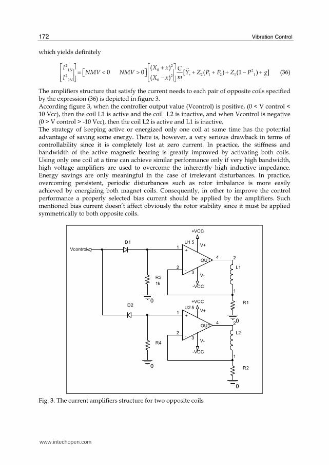
The amplifiers structure that satisfy the current needs to each pair of opposite coils specified by the expression (36) is depicted in figure 3. According figure 3, when the controller output value (Vcontrol) is positive, (0 < V control < 10 Vcc), then the coil L1 is active and the coil L2 is inactive, and when Vcontrol is negative (0 > V control > -10 Vcc), then the coil L2 is active and L1 is inactive. The strategy of keeping active or energized only one coil at same time has the potential advantage of saving some energy. There is, however, a very serious drawback in terms of controllability since it is completely lost at zero current. In practice, the stiffness and bandwidth of the active magnetic bearing is greatly improved by activating both coils. Using only one coil at a time can achieve similar performance only if very high bandwidth, high voltage amplifiers are used to overcome the inherently high inductive impedance. Energy savings are only meaningful in the case of irrelevant disturbances. In practice, overcoming persistent, periodic disturbances such as rotor imbalance is more easily achieved by energizing both magnet coils. Consequently, in other to improve the control performance a properly selected bias current should be applied by the amplifiers. Such mentioned bias current doesn’t affect obviously the rotor stability since it must be applied symmetrically to both opposite coils.
D1
D2
0
R2
-VCC
+VCC
U2
+1
-2
V+5
V-3
OUT4
R3
1k
R4
0
0
L1
1
2
L2
1
20
R1
+VCC
Vcontrol
-VCC
U1
+1
-2
V+5
V-3
OUT4
Fig. 3. The current amplifiers structure for two opposite coils
www.intechopen.com
AVC Using a Backstepping Design Technique
173
4. Implementation task
4.1 System description
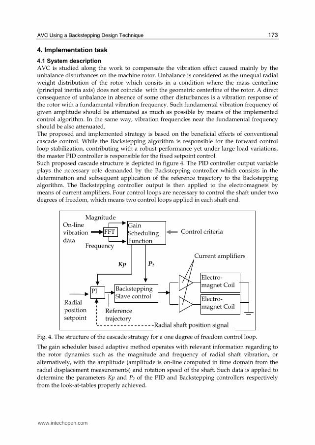
AVC is studied along the work to compensate the vibration effect caused mainly by the unbalance disturbances on the machine rotor. Unbalance is considered as the unequal radial weight distribution of the rotor which consits in a condition where the mass centerline (principal inertia axis) does not coincide with the geometric centerline of the rotor. A direct consequence of unbalance in absence of some other disturbances is a vibration response of the rotor with a fundamental vibration frequency. Such fundamental vibration frequency of given amplitude should be attenuated as much as possible by means of the implemented control algorithm. In the same way, vibration frequencies near the fundamental frequency should be also attenuated. The proposed and implemented strategy is based on the beneficial effects of conventional cascade control. While the Backstepping algorithm is responsible for the forward control loop stabilization, contributing with a robust performance yet under large load variations, the master PID controller is responsible for the fixed setpoint control. Such proposed cascade structure is depicted in figure 4. The PID controller output variable plays the necessary role demanded by the Backstepping controller which consists in the determination and subsequent application of the reference trajectory to the Backstepping algorithm. The Backstepping controller output is then applied to the electromagnets by means of current amplifiers. Four control loops are necessary to control the shaft under two degrees of freedom, which means two control loops applied in each shaft end.
Fig. 4. The structure of the cascade strategy for a one degree of freedom control loop.
The gain scheduler based adaptive method operates with relevant information regarding to
the rotor dynamics such as the magnitude and frequency of radial shaft vibration, or
alternatively, with the amplitude (amplitude is on-line computed in time domain from the
radial displacement measurements) and rotation speed of the shaft. Such data is applied to
determine the parameters Kp and P2 of the PID and Backstepping controllers respectively
from the look-at-tables properly achieved.
Magnitude
Radial shaft position signal
FFTOn-line vibrationdata
Frequency
Gain Scheduling Function
Control criteria
PI
Radial positionsetpoint
Referencetrajectory
Backstepping Slave control
Kp P2
Electro-magnet Coil
Current amplifiers
Electro-magnet Coil
www.intechopen.com

Vibration Control
174
Since the backstepping control algorithm is a model based technique, modelling errors are present when the values of parameters are not precisely determined. As consequence, the system control implementation must be performed under the set of selected model parameters matching the values of the test rig parameters. Such values are shown in table 1. The values selected for such set of model parameters are closely approached from the test rig data. Large modelling error parameter values yields dramatic results in terms of rotor stabilization and active vibration control performance. Applied backstepping theory is robust under no relevant modelling errors. Consequently, the rotor mass and inertia moment as well as magnetic field parameters must be acquired and applied to the control algorithm as much accurately as possible.
Parameter/Notation Value/Unit
Nominal air gap (X0) 0.001m
Number of turns of each coil (n) 400
Coils resistance (R) 2 Ohms
Cross sectional area of air gap (A) 0.000625m2
Rotor mass (m) 11 kg
Initial position of rotor (X0) -0.0008 m
Magnetic permeability of air gap (µ0) 1.256E-6
Table 1. Backstepping model parameters
As shown in figure 4, the closed loop system is controlled by means of a master PID controller, followed by the slave cascade Backstepping controller. Thus, the types of disturbances for which the combination of a cascade with a PID feedback control system exhibit effectiveness, are those generated by the unbalance effect of the rotor, the impeller or turbine shaft assembled to the rotor, which operates producing an abnormal radial force. Such radial force will be accurately detected measured and compensated. Consequently, such events will be compensated by the control current scheduled by the cascade Backstepping controller.
Fig. 5. The controller algorithm based on Agilent data acquisition hardware implemented under real time Matlab-Simulink software.
HWChannel0 agilentu2300 0
U2353A HWChannel1
HWChannel0 agilentu2300 0
U2353A HWChannel1
Analog Input (Single Sample)1
Analog Output (Single Sample)1
Cascade backstepping algorithm: Control Loop 1 Cascade backstepping algorithm: Control Loop 2
www.intechopen.com

AVC Using a Backstepping Design Technique
175
The implemented control type is based on a decentralized control structure (also called
“side-by side” or “local” control). In such type of control structure, every degree of freedom
to be controlled requires a feedback control loop. The control system applies the force
commands to attenuate shaft vibration while keeping the shaft into the desired radial
position, commonly symmetrically centred. The implementation of a shaft end vibration and
position control scheme is shown in figure 5. It consists of Agilent Technologies based I/O
hardware programmed under Matlab-Simulink.
The implemented test rig is considered as the traditional Jeffcott rotor as shown in figure 6 (a). The shaft turns around de bearing centreline and all rotating elements are concentric. This condition is depicted in detail (b) of figure 6. At very lo speeds, unbalance forces are negligible. As rotor speed increases, the straight shaft will deflect into the predictable mode shape according expression (37).
Fig. 6. The Jeffcott type rotor of the test rig: (a) rotor disk with unbalanced mass (M). (b) mass eccentricity (e) on the disc.
The only driving force in the system is the centrifugal force Fc due to the unbalance mass M. located at a radial distance e. The maximum bending deflection of the shaft is identified by r and the mass eccentricity by e. By inspection of the figure 6 it can be noted that the shaft and
disk are rotating at the operating speed ω. Simultaneously, the deflected shaft is whirling in the magnetic bearings at this speed. The mechanism driving this whirl is the centrifugal force generated by the eccentric mass on the disc. As rotor speed increases, the outward force increases in accordance with the normal centrifugal force Fc equation
2( )Fc M r e ω= ⋅ + ⋅ (37)
With regard to expression (37), the total radius of the mass unbalance M is composed of the
shaft bending r, and the eccentricity of the mass with respect to the shaft centreline e. Such
centrifugal forces will be attenuated by the active magnetic forces developed by the control
algorithm. Into the range of experimental rotating speeds, (0< ω < 50 rad/sec.) the bending
deflection is considered negligible and the only centrifugal force is due to the mass
eccentricity e. The unbalance characteristics for tests purposes consists of an unbalance mass
M of 1 kg. radially located with an eccentricity of 0.1 m.
Unbalance mass (M)
Uniform, masless shaft, flexible with stiffness
Rigid, frictionless bearings, no damping
e
G
ω
Shaft and disc center
Mass center
Bearing center
(a) (b)
www.intechopen.com
Vibration Control
176
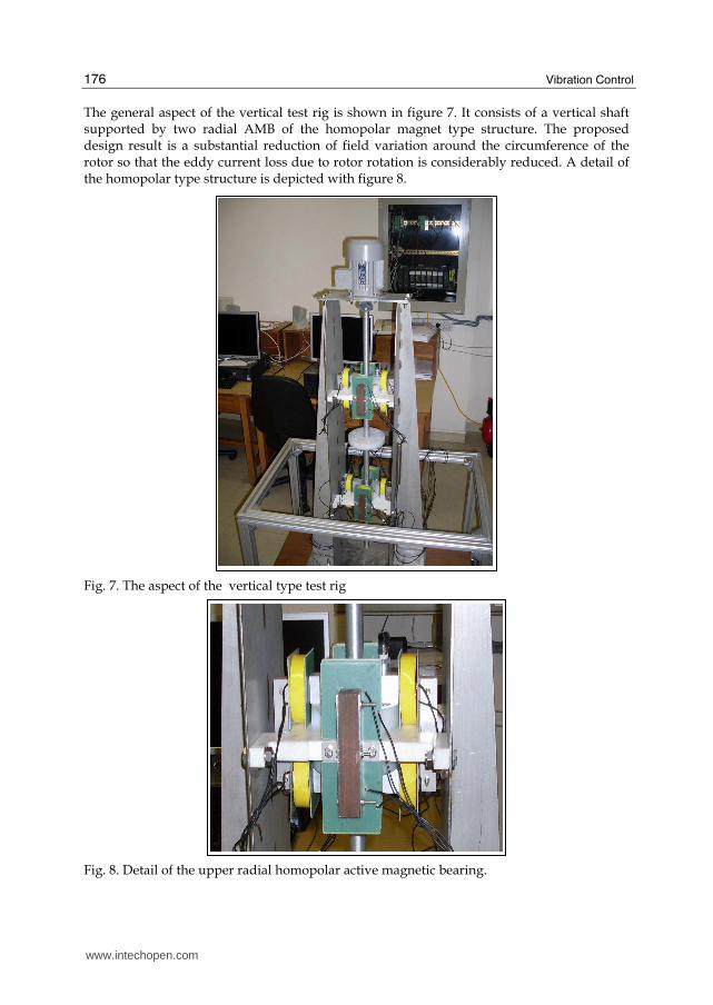
The general aspect of the vertical test rig is shown in figure 7. It consists of a vertical shaft supported by two radial AMB of the homopolar magnet type structure. The proposed design result is a substantial reduction of field variation around the circumference of the rotor so that the eddy current loss due to rotor rotation is considerably reduced. A detail of the homopolar type structure is depicted with figure 8.
Fig. 7. The aspect of the vertical type test rig
Fig. 8. Detail of the upper radial homopolar active magnetic bearing.
www.intechopen.com
AVC Using a Backstepping Design Technique
177
A detail of the upper radial magnetic bearing is shown in figure 8. The homopolar structures, being more complicated and expensive, exhibit the advantage that it produces much lower rotational losses since the rotor experiences less field variation when spinning and consequently has lower induced eddy currents. This property is of great importance in vacuum applications because any heat generated on the rotor must be removed by radiation transfer to the housing (rather than by convection as in non-vacuum AMB systems or conduction as in rolling element bearing systems): there is a high premium on rotor losses. The advantage of four-pole radial bearings, as illustrated in figures 7 and 8, is the fact that two pole pairs each can be assigned to the Cartesian coordinates x and y which are often used in mechanics. To drive the test rig, an electric motor is assembled at the upper shaft end, driven by a variable sped drive in order to test the AVC system at different rotation speeds.
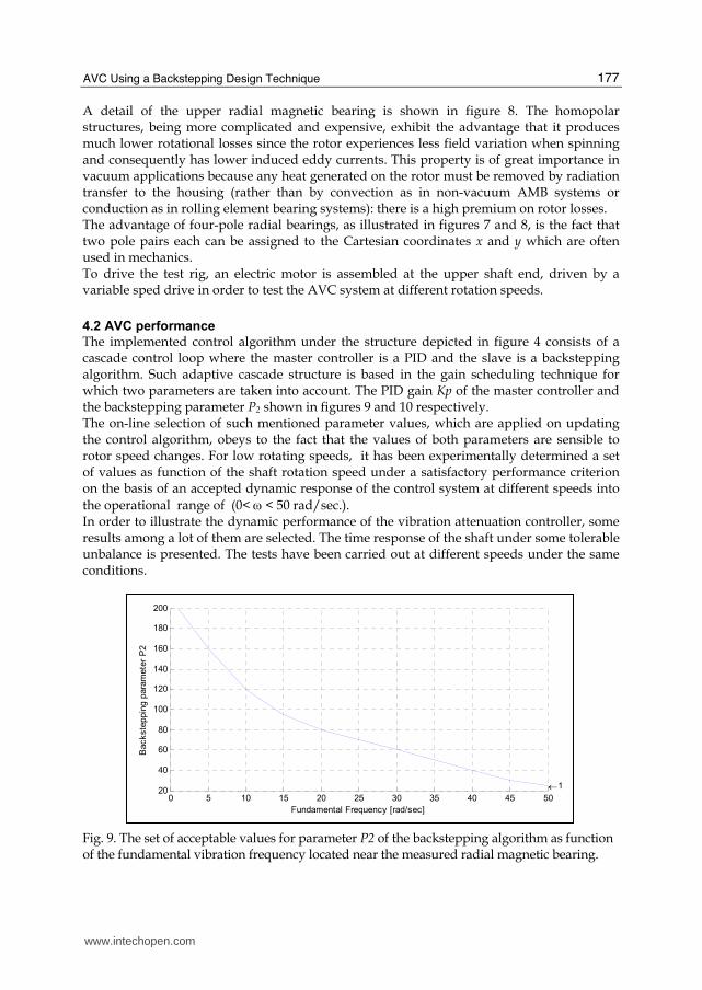
4.2 AVC performance
The implemented control algorithm under the structure depicted in figure 4 consists of a cascade control loop where the master controller is a PID and the slave is a backstepping algorithm. Such adaptive cascade structure is based in the gain scheduling technique for which two parameters are taken into account. The PID gain Kp of the master controller and the backstepping parameter P2 shown in figures 9 and 10 respectively. The on-line selection of such mentioned parameter values, which are applied on updating the control algorithm, obeys to the fact that the values of both parameters are sensible to rotor speed changes. For low rotating speeds, it has been experimentally determined a set of values as function of the shaft rotation speed under a satisfactory performance criterion on the basis of an accepted dynamic response of the control system at different speeds into the operational range of (0< ω < 50 rad/sec.). In order to illustrate the dynamic performance of the vibration attenuation controller, some results among a lot of them are selected. The time response of the shaft under some tolerable unbalance is presented. The tests have been carried out at different speeds under the same conditions.
Fig. 9. The set of acceptable values for parameter P2 of the backstepping algorithm as function of the fundamental vibration frequency located near the measured radial magnetic bearing.
0 5 10 15 20 25 30 35 40 45 5020
40
60
80
100
120
140
160
180
200
←1
Backste
ppin
g p
ara
mete
r P
2
Fundamental Frequency [rad/sec]
www.intechopen.com
Vibration Control
178
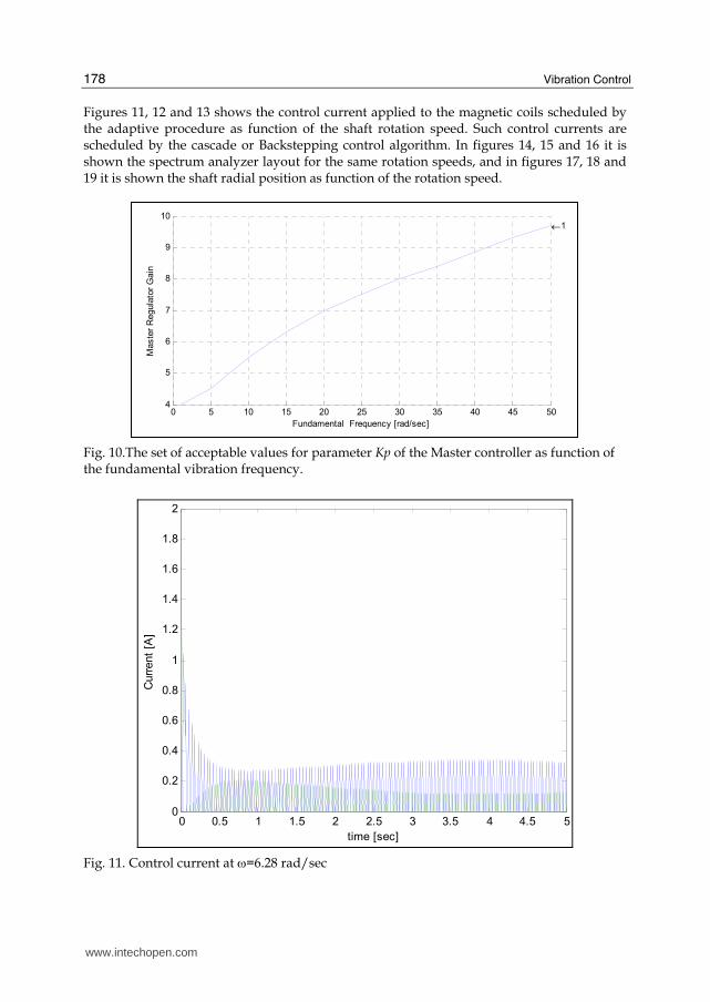
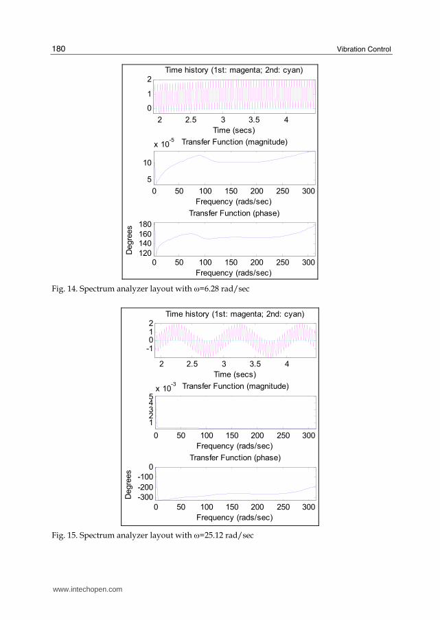
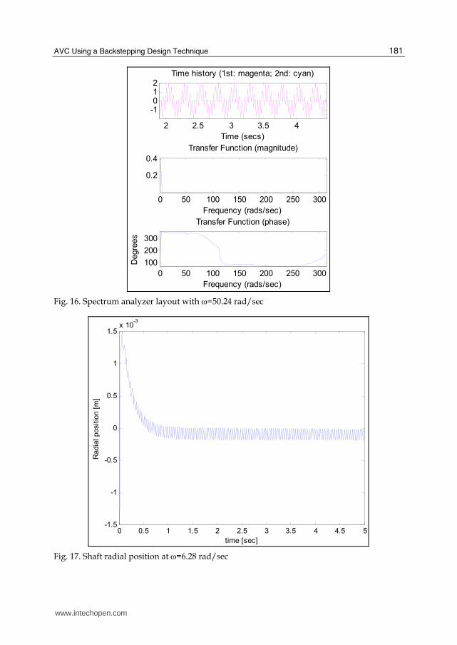
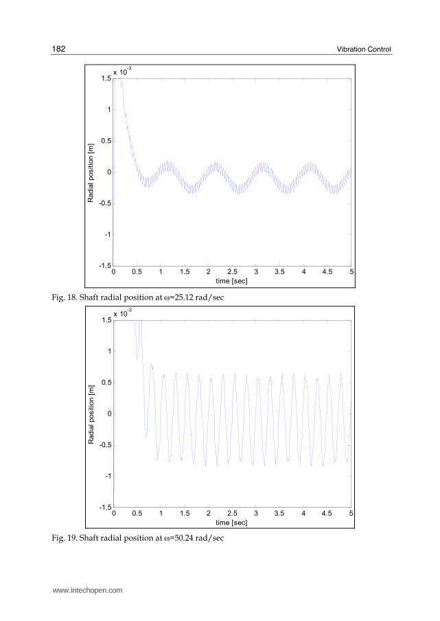
Figures 11, 12 and 13 shows the control current applied to the magnetic coils scheduled by the adaptive procedure as function of the shaft rotation speed. Such control currents are scheduled by the cascade or Backstepping control algorithm. In figures 14, 15 and 16 it is shown the spectrum analyzer layout for the same rotation speeds, and in figures 17, 18 and 19 it is shown the shaft radial position as function of the rotation speed.
Fig. 10.The set of acceptable values for parameter Kp of the Master controller as function of the fundamental vibration frequency.
0 0.5 1 1.5 2 2.5 3 3.5 4 4.5 50
0.2
0.4
0.6
0.8
1
1.2
1.4
1.6
1.8
2
time [sec]
Curr
ent
[A]
Fig. 11. Control current at ω=6.28 rad/sec
0 5 10 15 20 25 30 35 40 45 504
5
6
7
8
9
10 ←1
Maste
r R
egula
tor
Gain
Fundamental Frequency [rad/sec]
www.intechopen.com
AVC Using a Backstepping Design Technique
179
0 0.5 1 1.5 2 2.5 3 3.5 4 4.5 50
0.2
0.4
0.6
0.8
1
1.2
1.4
1.6
1.8
2
Curr
ent
[A]
time [sec]
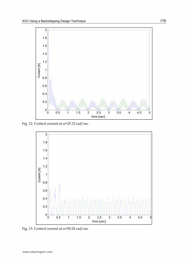
Fig. 12. Control current at ω=25.12 rad/sec
0 0.5 1 1.5 2 2.5 3 3.5 4 4.5 50
0.2
0.4
0.6
0.8
1
1.2
1.4
1.6
1.8
2
Curr
ent
[A]
time [sec]
Fig. 13. Control current at ω=50.24 rad/sec
www.intechopen.com
Vibration Control
180
2 2.5 3 3.5 4
0
1
2Time history (1st: magenta; 2nd: cyan)
Time (secs)
0 50 100 150 200 250 300
5
10
x 10-5 Transfer Function (magnitude)
Frequency (rads/sec)
0 50 100 150 200 250 300120
140160
180
Transfer Function (phase)
Frequency (rads/sec)
Degre
es
Fig. 14. Spectrum analyzer layout with ω=6.28 rad/sec
2 2.5 3 3.5 4
-1012
Time history (1st: magenta; 2nd: cyan)
Time (secs)
0 50 100 150 200 250 300
12345
x 10-3 Transfer Function (magnitude)
Frequency (rads/sec)
0 50 100 150 200 250 300
-300
-200
-100
0Transfer Function (phase)
Frequency (rads/sec)
Degre
es
Fig. 15. Spectrum analyzer layout with ω=25.12 rad/sec
www.intechopen.com
AVC Using a Backstepping Design Technique
181
2 2.5 3 3.5 4
-1012
Time history (1st: magenta; 2nd: cyan)
Time (secs)
0 50 100 150 200 250 300
0.2
0.4
Transfer Function (magnitude)
Frequency (rads/sec)
0 50 100 150 200 250 300
100
200
300
Transfer Function (phase)
Frequency (rads/sec)
Degre
es
Fig. 16. Spectrum analyzer layout with ω=50.24 rad/sec
0 0.5 1 1.5 2 2.5 3 3.5 4 4.5 5-1.5
-1
-0.5
0
0.5
1
1.5x 10
-3
Radia
l positio
n [
m]
time [sec]
Fig. 17. Shaft radial position at ω=6.28 rad/sec
www.intechopen.com
Vibration Control
182
0 0.5 1 1.5 2 2.5 3 3.5 4 4.5 5-1.5
-1
-0.5
0
0.5
1
1.5x 10
-3
time [sec]
Radia
l positio
n [
m]
Fig. 18. Shaft radial position at ω=25.12 rad/sec
0 0.5 1 1.5 2 2.5 3 3.5 4 4.5 5-1.5
-1
-0.5
0
0.5
1
1.5x 10
-3
time [sec]
Radia
l positio
n [
m]
Fig. 19. Shaft radial position at ω=50.24 rad/sec
www.intechopen.com
AVC Using a Backstepping Design Technique
183
4.2 Discussion of results
In spite of the fact that Backstepping design techniques has the drawbacks inherent to model
based techniques, the most relevant characteristic of such control strategy is the inherent
capacity to reject load disturbances under some tolerable modelling error. Furthermore, it
has been shown by simple inspection of the results that the capacity of the control strategy
to disturbances rejection, increases as function of the proper adjustment values of the
parameter Kp at the PID controller and parameter P2 of the Backstepping algorithm.
Parameter P1 doesn’t exhibit such property. In fact, the influence on the value of P1 on the
vibration attenuation is irrelevant. On the basis of the developed work, the coupled
dynamics of the test rig which includes the bed plate or platform and the Jeffcott type rotor,
a robust backstepping controller for vibration isolation is derived as results of the
experimental work. The results of the analysis of the achieved information show that the
control strategy can effectively attenuate low frequency vibrations in two DOF. Meanwhile,
to vibrations with time-varying parameters in different directions, vibration isolation
performance can also be improved. The actual values of the payload through vibration
isolation are greatly impacted by the parameter P2 of the backstepping algorithm and the
master controller gain Kp in the case of a cascade structure. Therefore, in order to enhance
the vibration isolation performance, the gain Kp and the parameter P2 should be carefully
chosen in order to satisfy the required performance under different operating conditions.
According to such idea, a gain scheduling strategy has been successfully applied. The range
of useful values for Kp and P2 experimentally determined, are such that 4 < Kp < 10, and 25 <
P2 < 220 as shown respectively in figures 9and 10. The validity of such results is into the
range of low rotational speeds, which for this test rig approaches a maximum speed of 50
rad/sec.
Some important influence factors of vibration isolation are considered in the cascade
backstepping design procedure, such as the inclination of the test rig, the rotational speed
changes, the inherent uncertainties including modelling errors and the base plate vibration
conditions obviously restricted to some limits experimentally determined. Thus, the robust
backstepping control method can fulfil the requirements of a vibration isolation alternative
for a variety of practical applications.
4.3 Conclusions
A feedback control under a cascade structure composed by a gain scheduling based
adaptive PID master controller associated to a gain scheduling based adaptive Backstepping
controller has been implemented. In such a cascade control structure, the PID master
controller is responsible for the reference or desired trajectory generation and the radial
position, while the slave backstepping controller contributes to the rotor global stabilization
and vibration suppression or attenuation.
Such a control strategy fulfils the two following objectives: a. Radial position control of the shaft by means of active magnetic bearings, and b. Vibration attenuation by active vibration control using the same actuators as for
active magnetic bearing control. With regard to the designed test rig mechanical structure, it must be taken into account that the absorbed vibration is transferred by the actuators to the base plate or stator. Consequently, in order to absorb the shaft vibration modes into the range of operational
www.intechopen.com
Vibration Control
184
speeds, the stator mass should be several times greater (in this case, ten times the mass of the stator bed plate) than the rotor mass. Gain scheduling based adaptation as function of vibration frequency and amplitude
contributes effectively to the vibration attenuation of rotor dynamics into the range of low
rotation speeds 0< ω < 50 rad/sec.
It has been shown experimentally that the vibration reduction is significant for rotors with
low external damping. However, in heavy rotating machines, very large forces would be
required and electromagnet based actuators under such conditions are not effective.
Gain scheduling adaptation as function of the vibration characteristics is very effective at
low rotation speeds, and outside the range of resonant frequencies. Although it can be
applied to attenuate resonant frequencies, obviously it is not so effective, because centrifugal
forces are very large, and actuators have not been designed to compensate so large forces.
To avoid resonant induced vibration, the rig structure must be designed so that resonant
frequencies are outside of the operational rotation speeds.
Since a great variety of control algorithms have been applied along the last three decades of
practical implementations, the experiences show that the effectiveness of a single PD or PID
is comparable to sophisticated control algorithms such the backstepping one.
5. Acknowledgments
This work has been partially supported by the XUNTA DE GALICIA under the grant DPI 1
IN825N cod_web:772.
6. References
B. Shafai, S. Beale, P. LaRocca, and E. Cusson, (1994), "Magnetic Bearing Control
Systems and Adaptive Forced Balancing", IEEE Control Systems, Volume 14, No. 2,
pp. 4-13.
C.R. Burrows and M.N. Sahinkaya, (1983), "Vibration Control of Multi-Mode Rotor-Bearing
Systems", Proceedings of the Royal Society of London, Vol. 386, pp. 77-94.
C.R. Burrows, M.N. Sahinkaya, and S. Clements, (1989)"Active Vibration Control of Flexible
Rotors: an Experimental and Theoretical Study", Proceedings of the Royal Society of
London, Vol. 422, pp. 123-146.
Francesc Pozo, Fayçll Ikhouane, Gisela Pujol, José Rodellar, (2006), “Adaptive Backstepping
Control of Hysteretic Base-Isolated Structures”, Journal of Vibration and Control.
2006; 12: 373-394
F. Matsumura, M. Fujita, and K. Okawa, (1990), "Modeling and Control of Magnetic
Bearing Systems Achieving a Rotation Around the Axis of Inertia", Proceedings of the
2nd International Symposium on Magnetic Bearings, July 12-14, 1990, Tokyo,
Japan.
Gerhard Schweitzer, Eric H. Maslen Editors, (2009),“Magnetic Bearings: Theory, Design, and
Application to Rotating Machinery”, DOI 10.1007/978-3-642-00497-1, Springer
Dordrecht Heidelberg London New York
Guang Lia, Amir Khajepour, (2005), “Robust control of a hydraulically driven flexible arm
using backstepping technique”, Journal of Sound and Vibration 280, 759 - 775
www.intechopen.com
AVC Using a Backstepping Design Technique
185
Hassan K. Khalil (2002). Nonlinear Systems. Prentice-Hall, third edition, ISBN: 0-13-067389-7,
Chap 4, pp 111-174.
H. Habermann and M. Brunet, (1984), "The Active Magnetic Bearing Enables Optimum
Damping of Flexible Rotors", ASME Paper 84-GT-117, 1984.
Knospe C. R., R.W. Hope, S.J. Fedigan, and R.D. Williams, (1993), "Adaptive On-Line Rotor
Balancing Using Digital Control", Proceedings of MAG '93 Magnetic Bearings,
Magnetic Drives, and Dry Gas Seals Conference, Technomic Publishing, Lancaster, PA,
July 1993.
Krstic, M., I. Kanellakopoulos, and P. Kokotovic, (1995). Nonlinear and Adaptive Control
Design. John Wiley & Sons, Inc. New York, NY, USA, (1995).
Krstic M., and H. Deng (1998). Stabilization of Nonlinear Uncertain Systems, (Springer Verlag,
Berlin).
LaSalle J. P., (1960), “Some extensions of Liapunov’s second method”. IRE Trans. Circuit
Theory, Vol. 7, pp. 520–527.
LaSalle J. P., (1968), “Stability theory for ordinary differential equations”, Journal of Differential
Equations vol. 4, , 57-65.
Qinglei Hu, (2009), “Robustadaptivebacksteppingattitudeandvibrationcontrol with L2-gain
performanceforflexiblespacecraftunder angular velocityconstraint”, Journal of
Sound and Vibration 327 , 285–298
R. Larsonneur and R. Herzog, (1994), "Feedforward compensation of Unbalance: New Results",
IUTAM Symposium, Bath, UK, September 1994.
R. Larsonneur, (1998), “Design and Control of Active Magnetic Bearing Systems for High Speed
Rotation”, PhD Thesis, Swiss Federal Institute of Technology, ETH Zurich,
Switzerland, June, 1998.
Sontag E. D., (1989),A ”universal” construction of Artstein’s theorem on nonlinear
stabilization”. Systems and Control Letters, Vol.13 (2), pp.117–123, 1998.
Sontag E.D., and Sussman, (1998) “Further comments on the stabilization of the
angular velocity of a rigid body”, Systems and Control Letters, Vol. 12, pp. 213-217,
1998.
T. Higuchi, M. Otsuka, T. Mizuno, and T. Ide, (1990), "Application of Periodic Learning
Control with Inverse Transfer Function Compensation in Totally Active Magnetic
Bearings", Proceedings of the 2nd International Symposium on Magnetic Bearings, July
12-14, 1990, Tokyo, Japan.
T. Higuchi, T. Mizuno, and M. Tsukamoto, (1990), "Digital Control System for Magnetic
Bearings with Automatic Balancing", Proceedings of the 2nd International Symposium
on Magnetic Bearings, July 12-14, 1990, Tokyo, Japan.
Tao Yang, Jia Ma, Zeng-Guang Hou, Min Tan (2009), “Robust backstepping control of active
vibration isolation using a stewart platform”, 2009 IEEE Int. Conf. on Robotics and
Automation,Volume , Issue , 12-17 May 2009 Page(s):1788 – 1793, 978-1-4244-2789-
5/09/$25.00 ©2009 IEEE, Digital Object Identifier:10.1109/ROBOT.2009.5152486,
Kobe, Japan, May 12-17, 2009.
V. Mañosa, F. Ikhouane, J. Rodellar, (2005), “Control of uncertain non-linear systems via
adaptive backstepping”, Journal of Sound and Vibration 280 657–680
www.intechopen.com

Vibration Control
186
Yoshizawa, T., (1966), “Stability theory in Liapunov's second method”, Mathematical Society of
Japan, http://www.ams.org/mathscinet-getitem?mr=MR0208086
Yoshizawa, T., (1966), “Stability and existence of a periodic solution“, J. Differential
Equations, Vol. 1 (1968), 121-129,
http://www.ams.org/mathscinet-getitem?mr=MR0222396
www.intechopen.com
Vibration ControlEdited by Mickaël Lallart
ISBN 978-953-307-117-6Hard cover, 380 pagesPublisher SciyoPublished online 18, August, 2010Published in print edition August, 2010
InTech EuropeUniversity Campus STeP Ri Slavka Krautzeka 83/A 51000 Rijeka, Croatia Phone: +385 (51) 770 447 Fax: +385 (51) 686 166www.intechopen.com
InTech ChinaUnit 405, Office Block, Hotel Equatorial Shanghai No.65, Yan An Road (West), Shanghai, 200040, China Phone: +86-21-62489820 Fax: +86-21-62489821
Vibrations are a part of our environment and daily life. Many of them are useful and are needed for manypurposes, one of the best example being the hearing system. Nevertheless, vibrations are often undesirableand have to be suppressed or reduced, as they may be harmful to structures by generating damages orcompromise the comfort of users through noise generation of mechanical wave transmission to the body. thepurpose of this book is to present basic and advanced methods for efficiently controlling the vibrations andlimiting their effects. Open-access publishing is an extraordinary opportunity for a wide dissemination of highquality research. This book is not an exception to this, and I am proud to introduce the works performed byexperts from all over the world.
How to referenceIn order to correctly reference this scholarly work, feel free to copy and paste the following:
R. Ferreiro Garcia, F. Fraguela Diaz and A. De Miguel Catoira (2010). AVC Using a Backstepping DesignTechnique, Vibration Control, Mickaël Lallart (Ed.), ISBN: 978-953-307-117-6, InTech, Available from:http://www.intechopen.com/books/vibration-control/active-vibration-control-using-a-backstepping-design-technique

© 2010 The Author(s). Licensee IntechOpen. This chapter is distributedunder the terms of the Creative Commons Attribution-NonCommercial-ShareAlike-3.0 License, which permits use, distribution and reproduction fornon-commercial purposes, provided the original is properly cited andderivative works building on this content are distributed under the samelicense.