Embed Size (px)
DESCRIPTION
Avaya CVLAN Integration wiht NICE Perform
Citation preview

Insight from InteractionsTM
NICE Perform®

NICE Systems Ltd. shall bear no responsibility or liability to a client or to any other person or entity with respect to liability, loss or damage caused or alleged to be caused directly or indirectly by any NICE product. This includes, but is not limited to, any interruption of service, loss of business or anticipatory profits or consequential damage resulting from the use or operation of any NICE products.
Information in this document is subject to change without notice and does not represent a commitment on the part of NICE Systems Ltd. The systems described in this document are furnished under a license agreement or nondisclosure agreement.
All information included in this document, such as text, graphics, photos, logos and images, is the exclusive property of NICE Systems Ltd. and protected by United States and international copyright laws.
Permission is granted to view and photocopy (or print) materials from this document for personal, non-commercial use only. Any other copying, distribution, retransmission or modification of the information in this document, whether in electronic or hard copy form, without the express prior written permission of NICE Systems Ltd., is strictly prohibited. In the event of any permitted copying, redistribution or publication of copyrighted material, no changes in, or deletion of, author attribution, trademark legend or copyright notice shall be made.
All contents of this document are: Copyright © 2008 NICE Systems Ltd. All rights reserved.
This product is covered by one or more of the following US patents:
360o View, ACTIMIZE, Actimize logo, Alpha, Customer Feedback, Dispatcher Assessment, Encorder, eNiceLink, Executive Connect, Executive Insight, FAST, FAST alpha Blue, FAST alpha Silver, FAST Video Security, Freedom, Freedom Connect, IEX, Interaction Capture Unit, Insight from Interactions, Investigator, Last Message Replay, Mirra, My Universe, NICE, NICE logo, NICE Analyzer, NiceCall, NiceCall Focus, NiceCLS, NICE Inform, NICE Learning, NiceLog, NICE Perform, NiceScreen, NICE SmartCenter, NICE Storage Center, NiceTrack, NiceUniverse, NiceUniverse Compact, NiceVision, NiceVision Alto, NiceVision Analytics, NiceVision ControlCenter, NiceVision Digital, NiceVision Harmony, NiceVision Mobile, NiceVision Net, NiceVision NVSAT, NiceVision Pro, Performix, Playback Organizer, Renaissance, Scenario Replay, ScreenSense, Tienna, TotalNet, TotalView, Universe, Wordnet are trademarks and registered trademarks of NICE Systems Ltd. All other registered and unregistered trademarks are the property of their respective owners.
Applications to register certain of these marks have been filed in certain countries, including Australia, Brazil, the European Union, Israel, Japan, Mexico, Argentina and the United States. Some of such registrations have matured to registrations.
385A0284-09 Rev. A1
4,893,197
5,396,371
6,044,355
6,252,947
6,785,369
6,937,706
7,085,728
5,185,780
5,446,603
6,115,746
6,330,025
6,785,370
6,959,079
7,203,655
5,216,744
5,457,782
6,122,665
6,542,602
6,856,343
6,965,886
7,240,328
5,274,738
5,590,188
6,192,346
6,564,368
6,865,604
6,970,829
7,305,082
5,289,368
5,819,005
6,246,752
6,694,374
6,870,920
7,010,106
5,325,292
5,911,134
6,249,570
6,728,345
6,871,229
7,010,109
5,339,203
5,937,029
6,252,946
6,775,372
6,880,004
7,058,589

For assistance please contact your local supplier or the nearest NICE Systems Customer Service Center:
EMEA Region: (Europe, Middle East, Africa)Tel: +972-9-775-3800Fax: +972-9-775-3000email: [email protected]
APAC Region: (Asia/Pacific)Tel: +852-8338-9818Fax: +852-2802-1800email: [email protected]
The Americas Region: (North, Central, South America)Tel: 1-800-NICE-611Fax: +720-264-4012email: [email protected]
Israel:Tel: 09-775-3333Fax: 09-775-3000email: [email protected]
For general information on NICE Systems products please contact your local distributor or the nearest NICE Systems office:
Please send all queries, comments, and suggestions pertaining to this document to [email protected]
Please visit NICE at www.nice.com
International Headquarters-IsraelTel: +972-9-775-3100Fax: +972-9-775-3070email: [email protected]
North AmericaTel: 1-800-663-5601Fax: +201-356-2197email: [email protected]
United KingdomTel: +44-8707-22-4000Fax: +44-8707-22-4500
GermanyTel: +49-(0)-69-97177-0Fax: +49-(0)-69-97177-200
FranceTel: +33-(0)1-41-38-5000Fax: +33-(0)1-41-38-5001
Hong-KongTel: +852-2598-3838Fax: +852-2802-1800
NICE invites you to join the NICE User Group (NUG).
Visit the NUG Website at www.niceusergroup.org, and follow the instructions.

Revision HistoryIntegration with CVLAN
Revision Modification Date Description
A1 January 2008 • Business Data on page 25 – Updated section.
• Installing the Switch Driver on page 81– Updated screens and procedure.
• Updated the following Troubleshooting procedures (light changes):
• Missing VDN Information in Database on page 94.
• Failed to Monitor Device on page 94.
• Monitor End Event is Received on page 95.
• Added testing and Debugging tool: CTi Console Viewer on page 129.

Blank page for double-sided printing.

Contents
1Introduction 11
NICE Perform Site Installation Overview . . . . . . . . . . . . . . . . . . . . . . . . . . . . 12Avaya CVLAN Integration Workflow . . . . . . . . . . . . . . . . . . . . . . . . . . . . . . . 13Integration Description . . . . . . . . . . . . . . . . . . . . . . . . . . . . . . . . . . . . . . . . . . 14System Architecture . . . . . . . . . . . . . . . . . . . . . . . . . . . . . . . . . . . . . . . . . . . . 15
Components . . . . . . . . . . . . . . . . . . . . . . . . . . . . . . . . . . . . . . . . . . . . . . . . 15
Recording Modes . . . . . . . . . . . . . . . . . . . . . . . . . . . . . . . . . . . . . . . . . . . . . . 17Recording Methods . . . . . . . . . . . . . . . . . . . . . . . . . . . . . . . . . . . . . . . . . . . . . 17
Extension-Side Recording Architecture . . . . . . . . . . . . . . . . . . . . . . . . . . . 18Trunk-Side Recording Architecture . . . . . . . . . . . . . . . . . . . . . . . . . . . . . . 19DMCC-Based Active VoIP Recording Architecture . . . . . . . . . . . . . . . . . . . 20
Avaya Components . . . . . . . . . . . . . . . . . . . . . . . . . . . . . . . . . . . . . . . 20NICE Components . . . . . . . . . . . . . . . . . . . . . . . . . . . . . . . . . . . . . . . . 21
Passive VoIP Recording Architecture . . . . . . . . . . . . . . . . . . . . . . . . . . . . . 22Avaya Components . . . . . . . . . . . . . . . . . . . . . . . . . . . . . . . . . . . . . . . 22Customer Components . . . . . . . . . . . . . . . . . . . . . . . . . . . . . . . . . . . . . 23NICE Components . . . . . . . . . . . . . . . . . . . . . . . . . . . . . . . . . . . . . . . . 23
Supported Database Fields. . . . . . . . . . . . . . . . . . . . . . . . . . . . . . . . . . . . . . . 24Business Data . . . . . . . . . . . . . . . . . . . . . . . . . . . . . . . . . . . . . . . . . . . . . . 25
Limitations . . . . . . . . . . . . . . . . . . . . . . . . . . . . . . . . . . . . . . . . . . . . . . . . . . . . 26
2Switch Configuration Guidelines 29
Connecting the Main Distribution Frame (MDF) . . . . . . . . . . . . . . . . . . . . . . 30Configuring DS1 Cards for Instant Callback . . . . . . . . . . . . . . . . . . . . . . . . . 31
Connecting DS1 Card Recording Inputs . . . . . . . . . . . . . . . . . . . . . . . . . . . 31
Contents
NICE Perform® Release 3: Integration with Avaya CVLAN (Rev. A1)
7
Configuring DS1 Cards - Basic Parameters . . . . . . . . . . . . . . . . . . . . . . . . 32Configuring DS1 Cards - E1 Trunks . . . . . . . . . . . . . . . . . . . . . . . . . . . . . . 35Configuring DS1 Cards - T1 Trunks . . . . . . . . . . . . . . . . . . . . . . . . . . . . . . 37
3Preparing the Avaya Environment 43
Preparing the AES environment for CVLAN . . . . . . . . . . . . . . . . . . . . . . . . . 44Configure the Switch on AES . . . . . . . . . . . . . . . . . . . . . . . . . . . . . . . . . . . 44
Configuring the AES on the ACM . . . . . . . . . . . . . . . . . . . . . . . . . . . . . 45Define the CTI Link . . . . . . . . . . . . . . . . . . . . . . . . . . . . . . . . . . . . . . . . . . . 47Configure the CTI Link Connection . . . . . . . . . . . . . . . . . . . . . . . . . . . . . . . 47Verify the CTI Link . . . . . . . . . . . . . . . . . . . . . . . . . . . . . . . . . . . . . . . . . . . 48
4Integrating Avaya CVLAN with NICE Perform 49
Installing the CVLAN Client on the NICE Interaction Center. . . . . . . . . . . . . 50Before You Begin the Integration . . . . . . . . . . . . . . . . . . . . . . . . . . . . . . . . . . 52
CVLAN Server . . . . . . . . . . . . . . . . . . . . . . . . . . . . . . . . . . . . . . . . . . . . . . 52CVLAN Client . . . . . . . . . . . . . . . . . . . . . . . . . . . . . . . . . . . . . . . . . . . . . . . 52Configuration Information . . . . . . . . . . . . . . . . . . . . . . . . . . . . . . . . . . . . . . 52
CTI Interface Configuration . . . . . . . . . . . . . . . . . . . . . . . . . . . . . . . . . . 52Connection Manager Configuration . . . . . . . . . . . . . . . . . . . . . . . . . . . . 53Switch Driver Configuration . . . . . . . . . . . . . . . . . . . . . . . . . . . . . . . . . . 53
SNMP Service . . . . . . . . . . . . . . . . . . . . . . . . . . . . . . . . . . . . . . . . . . . . . . 53
Configuring the CTI Interface . . . . . . . . . . . . . . . . . . . . . . . . . . . . . . . . . . . . . 54Configuring the Connection Manager . . . . . . . . . . . . . . . . . . . . . . . . . . . . . . 66Creating the Switch Driver . . . . . . . . . . . . . . . . . . . . . . . . . . . . . . . . . . . . . . . 70Installing the Switch Driver . . . . . . . . . . . . . . . . . . . . . . . . . . . . . . . . . . . . . . 81
5Troubleshooting 91
Open Case Procedure . . . . . . . . . . . . . . . . . . . . . . . . . . . . . . . . . . . . . . . . . . . 92Missing Login/Logout Error . . . . . . . . . . . . . . . . . . . . . . . . . . . . . . . . . . . . . . 93Missing VDN Information in Database . . . . . . . . . . . . . . . . . . . . . . . . . . . . . . 94
8 Contents
NICE Perform® Release 3: Integration with Avaya CVLAN (Rev. A1)
Failed to Monitor Device . . . . . . . . . . . . . . . . . . . . . . . . . . . . . . . . . . . . . . . . . 94Open Connection Failure . . . . . . . . . . . . . . . . . . . . . . . . . . . . . . . . . . . . . . . . 95Monitor End Event is Received . . . . . . . . . . . . . . . . . . . . . . . . . . . . . . . . . . . 95ISDN Trunk - Alerting Event . . . . . . . . . . . . . . . . . . . . . . . . . . . . . . . . . . . . . . 96Calls Are Reported With The Wrong Direction . . . . . . . . . . . . . . . . . . . . . . . 96Connection Manager and Driver Fail to Connect to the AES . . . . . . . . . . . . 97AES Environment: General Troubleshooting Tips . . . . . . . . . . . . . . . . . . . . 98Client Cannot Connect to CVLAN Server . . . . . . . . . . . . . . . . . . . . . . . . . . . 100
6NICE Testing and Debugging Tools 101
NICE Events Spy . . . . . . . . . . . . . . . . . . . . . . . . . . . . . . . . . . . . . . . . . . . . . . 102Setting Up the Events Spy . . . . . . . . . . . . . . . . . . . . . . . . . . . . . . . . . . . . 102Receiving Events . . . . . . . . . . . . . . . . . . . . . . . . . . . . . . . . . . . . . . . . . . . 104Saving Events . . . . . . . . . . . . . . . . . . . . . . . . . . . . . . . . . . . . . . . . . . . . . . 105Setting up the SimCTILink Tool . . . . . . . . . . . . . . . . . . . . . . . . . . . . . . . . 106
NICE Debug Service . . . . . . . . . . . . . . . . . . . . . . . . . . . . . . . . . . . . . . . . . . . 107Setting Up the NICE Debug Service . . . . . . . . . . . . . . . . . . . . . . . . . . . . . 107Accessing the NICE Debug Service . . . . . . . . . . . . . . . . . . . . . . . . . . . . . 112
Connection Manager Monitor . . . . . . . . . . . . . . . . . . . . . . . . . . . . . . . . . . . . 113Setting Up the Connection Manager Monitor . . . . . . . . . . . . . . . . . . . . . . . 113Managing the Connection Manager Monitor . . . . . . . . . . . . . . . . . . . . . . . 117
Log Manager System . . . . . . . . . . . . . . . . . . . . . . . . . . . . . . . . . . . . . . . . . . 119Log Manager . . . . . . . . . . . . . . . . . . . . . . . . . . . . . . . . . . . . . . . . . . . . . . 119Log Manager Services . . . . . . . . . . . . . . . . . . . . . . . . . . . . . . . . . . . . . . . 121Log Viewer . . . . . . . . . . . . . . . . . . . . . . . . . . . . . . . . . . . . . . . . . . . . . . . . 121
CAPI Spy . . . . . . . . . . . . . . . . . . . . . . . . . . . . . . . . . . . . . . . . . . . . . . . . . . . . 123CAPI Spy Plug-in . . . . . . . . . . . . . . . . . . . . . . . . . . . . . . . . . . . . . . . . . . . 123CAPI Spy Utility . . . . . . . . . . . . . . . . . . . . . . . . . . . . . . . . . . . . . . . . . . . . 126Changing Connection Details . . . . . . . . . . . . . . . . . . . . . . . . . . . . . . . . . . 128
CTi Console Viewer . . . . . . . . . . . . . . . . . . . . . . . . . . . . . . . . . . . . . . . . . . . . 129
9 Contents
NICE Perform® Release 3: Integration with Avaya CVLAN (Rev. A1)

ACVLAN Additional Parameters 133
CTI Interface - Additional Switch Parameters . . . . . . . . . . . . . . . . . . . . . . . 134Importing Text Files . . . . . . . . . . . . . . . . . . . . . . . . . . . . . . . . . . . . . . . . . . . 136Reporting Levels . . . . . . . . . . . . . . . . . . . . . . . . . . . . . . . . . . . . . . . . . . . . . . 138Logger Parameters for Instant Callback . . . . . . . . . . . . . . . . . . . . . . . . . . . 140Connection Manager - Additional Parameters . . . . . . . . . . . . . . . . . . . . . . . 141Connection Manager - Interface Parameters . . . . . . . . . . . . . . . . . . . . . . . . 143Switch Driver - Additional Parameters . . . . . . . . . . . . . . . . . . . . . . . . . . . . . 145Driver Interface - Additional Parameters . . . . . . . . . . . . . . . . . . . . . . . . . . . 147
Index 149
10 Contents
NICE Perform® Release 3: Integration with Avaya CVLAN (Rev. A1)

1
Introduction
This guide describes the integration between the NICE Interaction Center and the Avaya CVLAN Interface, when setting up a NICE Perform system.
Contents
NICE Perform Site Installation Overview......................................................................12
Avaya CVLAN Integration Workflow .............................................................................13
Integration Description ..................................................................................................14
System Architecture.......................................................................................................15
Recording Modes ...........................................................................................................17
Recording Methods ........................................................................................................17
Supported Database Fields ...........................................................................................24
Limitations.......................................................................................................................26
NOTE: For an updated list of supported versions, refer to the Integration Description Document (IDD).
Chapter 1: Introduction
NICE Perform® Release 3: Integration with Avaya CVLAN (Rev. A1)
11

NICE Perform Site Installation Overview
NICE Perform Site Installation Overview
NOTE: Refer to the Site Installation Workflow Guide for a detailed overview of the NICE Perform site installation workflow.The Site Installation Workflow Guide provides general guidelines and procedures for installing NICE Perform at your site, and indicates the exact point during site installation at which to perform switch integrations.
NiceLog High Density Logger
Install SQL + Databases
Interaction Capture Unit (ICU)
Mandatorycomponent
Optionalcomponent
Legend Prepare Machines
Connect
Install relevant optional components:
Define in System Administrator
NICE VoIP Logger
Perform Required Installation and Acceptance Test Procedures
Define in System Administrator
Install NICE Perform Applications
Define in System Administrator
Define in System Administrator
Define in System Administrator
Install NMS
Install and Configure Switch Integrations
Install NICE Interactions Center
Install VoIP Recording Gateway (VRG)
You are Here
NiceScreenScreenSenseReporter Server
NICE Storage CenterMedia LibraryPlayback Server and/or Feedback
Audio Analysis
Define Channel Mapping in the System Administrator
12 Chapter 1: Introduction
NICE Perform® Release 3: Integration with Avaya CVLAN (Rev. A1)
Avaya CVLAN Integration Workflow
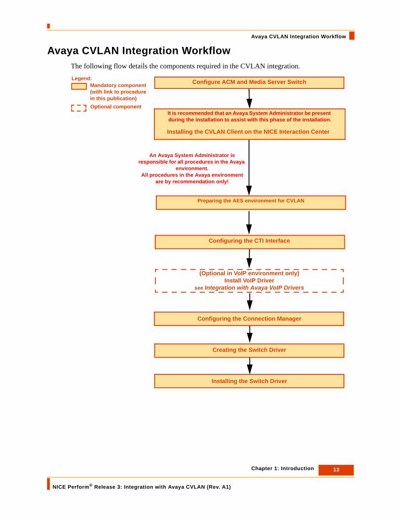
Avaya CVLAN Integration Workflow The following flow details the components required in the CVLAN integration.
Installing the CVLAN Client on the NICE Interaction Center
Configuring the CTI Interface
Configuring the Connection Manager
Creating the Switch Driver
Installing the Switch Driver
(Optional in VoIP environment only)Install VoIP Driver
see Integration with Avaya VoIP Drivers
Preparing the AES environment for CVLAN
It is recommended that an Avaya System Administrator be present during the installation to assist with this phase of the installation.
An Avaya System Administrator is responsible for all procedures in the Avaya
environment.All procedures in the Avaya environment
are by recommendation only!
Legend:
Optional component
Configure ACM and Media Server SwitchMandatory component (with link to procedure in this publication)
13 Chapter 1: Introduction
NICE Perform® Release 3: Integration with Avaya CVLAN (Rev. A1)
Integration Description
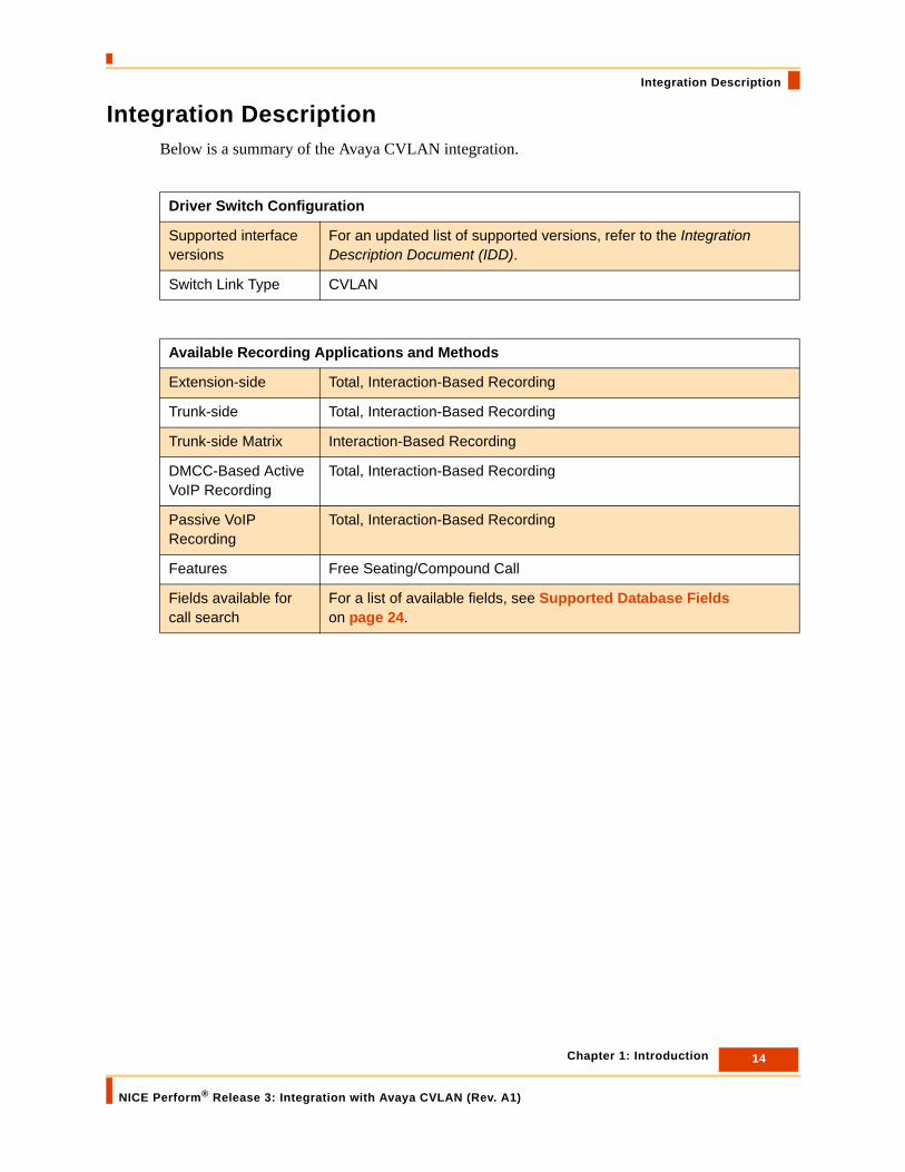
Integration DescriptionBelow is a summary of the Avaya CVLAN integration.
Driver Switch Configuration
Supported interface versions
For an updated list of supported versions, refer to the Integration Description Document (IDD).
Switch Link Type CVLAN
Available Recording Applications and Methods
Extension-side Total, Interaction-Based Recording
Trunk-side Total, Interaction-Based Recording
Trunk-side Matrix Interaction-Based Recording
DMCC-Based Active VoIP Recording
Total, Interaction-Based Recording
Passive VoIP Recording
Total, Interaction-Based Recording
Features Free Seating/Compound Call
Fields available for call search
For a list of available fields, see Supported Database Fields on page 24.
14 Chapter 1: Introduction
NICE Perform® Release 3: Integration with Avaya CVLAN (Rev. A1)

System Architecture
System ArchitectureThe CVLAN Client must be installed on the NICE Interaction Center. The NICE Interaction Center communicates with the CVLAN Interface configured on the AES server, as illustrated in the diagram below.Figure 1-1 Avaya CVLAN Integration Architecture
Components
• Avaya Communication Manager (ACM): Avaya call processing software.
The ACM includes the following components:
• Media Server: The Media Server runs the ACM software, and performs real-time management of the calls.
• Media Gateway: The Media Gateway performs signaling and audio conversion. It is controlled by the Media Server and hosts the interface cards (analog, digital, CLAN, MedPro and so on).
• CVLAN: CVLAN is an Application Programming Interface (API) that enables applications to communicate with the Avaya Communication Manager (ACM). That is, to send and receive ASAI-IP Messages over shared ASAI-IP links on TCP/IP (see page 14 for supported interface versions).
CVLAN consists of two components, a CVLAN Client and a CVLAN Server:
• The CVLAN Client must be installed on the NICE Interaction Center. It provides clients with access to the ACM via the CVLAN Server.
Avaya Communication Manager (ACM)
LAN
Logger
Analog / Digital Agent IP ExtensionsE1/T1 Trunks
NICE Interaction Center (CLS)
AES/CVLAN Server
AES/CVLAN Client
Media Server
Media Gateway
Media Server
CLA
N
Client Workstation
NMS ServerNICE
Environment
AVAYA Environment
Analog / Digital Agent IP Extensions
Logger connection is dependant on recording method
15 Chapter 1: Introduction
NICE Perform® Release 3: Integration with Avaya CVLAN (Rev. A1)

System Architecture
• The CVLAN Server provides LAN connectivity to remote workstations that require access to the CVLAN API.
• CLAN (Control LAN): Connects the ACM to the client LAN, which gives the ability for the IP phones and the AES to communicate over TCP/IP with the ACM. The CLAN includes a 10/100 BaseT Ethernet interface. It simplifies the connections between adjunct equipment and the Communication Manager and provides TCP/IP connectivity over Ethernet connections to applications, such as the AES, IP phones and soft phones.
• Avaya AES (Application Enablement Services): is a platform capable of running the following services:
• TSAPI
• CVLAN
• DMCC (Device Media Call Control)
• SMS (System Management Service)
• Logger: The Logger is a digital voice logging system. Loggers continuously and simultaneously record and archive audio from multiple sources. Audio is recorded to the hard drive of the Logger for immediate playback capability.
• NICE Interaction Center (CLS): The NICE Interaction Center communicates with the Avaya switch via CVLAN. Through communication with the CVLAN Interface configured on the AES server, the NICE Interaction Center learns the call status, monitors call events and stores them in its databases. A user can then query its database, find a call and play it back.
16 Chapter 1: Introduction
NICE Perform® Release 3: Integration with Avaya CVLAN (Rev. A1)

Recording Modes
Recording ModesDepending on your CTI switch configuration, the following recording modes are available:
Recording MethodsThe following recording methods are available:
• Extension-side recording - NiceLog connects directly to the extensions and taps them. This connectivity is usually used for Total Recording. See Extension-Side Recording Architecture on page 18 for details.
• Trunk-side recording - NiceLog connects to trunks. This connectivity is used for Total Recording and Selective Recording. See Trunk-Side Recording Architecture on page 19 for details.
• DMCC-Based Active VoIP Recording - Audio packets are sent directly to the NICE VoIP Logger’s IP address. This connectivity is used for Total Recording, Selective Recording and ROD. See DMCC-Based Active VoIP Recording Architecture on page 20 for details.
• Active VoIP Recording with VRG
• Active VoIP Recording with VRA
• Passive VoIP Recording - NICE VoIP Logger receives sniffed (or mirrored) audio packets. This connectivity is used for Total Recording, Selective Recording and ROD. See Passive VoIP Recording Architecture on page 22 for details.
• Total Recording Records all calls for all connected inputs: All calls (agent-to-customer, customer-to-agent, and agent-to-agent) are recorded. This type of recording is used for resolving disputes.
When Total Recording is implemented in a Trunk-side configuration, internal (agent-to-agent) calls are not recorded.
• Interaction-Based Recording
Records selected calls (interactions) based on filter criteria: The user selects complete or parts of calls to be recorded according to a predefined schedule or criteria (for example, calls to and from the sales department).
Interaction-Based Recording can be:
• Rule-Based
• Statistical for QM
• ROD (Recording on Demand)
17 Chapter 1: Introduction
NICE Perform® Release 3: Integration with Avaya CVLAN (Rev. A1)

Recording Methods
Extension-Side Recording Architecture
The NiceLog Logger supports Extension-side recording. NiceLog Loggers record directly from agent extensions, and are configured to receive direct parallel inputs to the digital extensions. Each Logger saves recordings on its hard disks for immediate playback, and archives the calls for long-term storage. Figure 1-2 Extension-Side Recording Configuration
• The NiceLog Logger is connected to each extension of the switch the customer wants to record. The Logger input is connected to the main Distribution Frame (MDF).
• The CTI server sends call data in real time as each call is initiated. The NICE Interaction Center determines whether or not to record the call.
Customer Requirements
For an updated list of supported versions, refer to the IDD.
Media ServerMedia Server
E1/T1 Trunks
LAN
Client Workstation
Analog / Digital Agent Extensions
NICE Interaction Center (CLS) Logger
Main Distribution Frame (MDF)
AES/CVLAN Client
Avaya Communication Manager (ACM)Media Server
Media Gateway
Media Server
CLA
N
NICE Environment
AVAYA Environment
NMS Server
AES/CVLAN Server
18 Chapter 1: Introduction
NICE Perform® Release 3: Integration with Avaya CVLAN (Rev. A1)
Recording Methods
Trunk-Side Recording Architecture
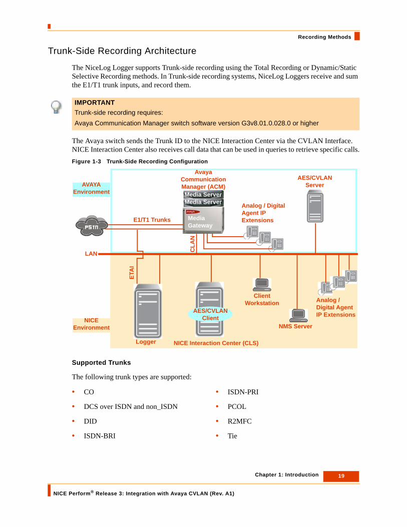
The NiceLog Logger supports Trunk-side recording using the Total Recording or Dynamic/Static Selective Recording methods. In Trunk-side recording systems, NiceLog Loggers receive and sum the E1/T1 trunk inputs, and record them.
The Avaya switch sends the Trunk ID to the NICE Interaction Center via the CVLAN Interface. NICE Interaction Center also receives call data that can be used in queries to retrieve specific calls.Figure 1-3 Trunk-Side Recording Configuration
Supported Trunks
The following trunk types are supported:
IMPORTANTTrunk-side recording requires: Avaya Communication Manager switch software version G3v8.01.0.028.0 or higher
• CO • ISDN-PRI
• DCS over ISDN and non_ISDN • PCOL
• DID • R2MFC
• ISDN-BRI • Tie
Avaya Communication Manager (ACM)
LAN
Logger
Analog / Digital Agent IP ExtensionsE1/T1 Trunks
NICE Interaction Center (CLS)
AES/CVLAN Server
AES/CVLAN Client
ETA
I
Media Server
Media Gateway
Media ServerC
LAN
Client Workstation
NMS ServerNICE
Environment
AVAYA Environment
Analog / Digital Agent IP Extensions
19 Chapter 1: Introduction
NICE Perform® Release 3: Integration with Avaya CVLAN (Rev. A1)

Recording Methods
Customer Requirements
For an updated list of supported versions, refer to the IDD.
DMCC-Based Active VoIP Recording Architecture
In Active VoIP Recording, audio packets are sent directly to the NICE VoIP Logger’s IP address. This is in contrast to Passive VoIP Recording, where the NICE VoIP Logger must be configured as a destination port of a mirroring session in the LAN Switch.Figure 1-4 Active VoIP Recording Configuration
Avaya Components
• DMCC: Provides recording hooks which serve third-party integrations. In the NICE Systems integration with the DMCC environment, the DMCC connector server enables registration of soft/DMCC VE phones to the ACM. These soft/DMCC VE phones then observe extensions that are set to be recorded in the ACM System. The observed phones can be any type of phone - IP, digital, or analog.
• IP Media Resource (or MedPro board): Provides VoIP audio access to the switch for local stations and for outside trunks. It is on an H.323 audio platform and includes a 10/100 BaseT Ethernet interface.
LAN
Logger
Analog / Digital Agent IP Extension
NICE Interaction Center (CLS)
AES DMCC/CVLAN
Media Provider Controller
Client Workstation
NMS Server
Avaya Communication Manager (ACM)Media Server
Media Gateway
Media Server
NICE Environment
AVAYA Environment
AES/CVLAN Client
CLA
N
Med
Pro
Analog / Digital Agent IP
Extension
20 Chapter 1: Introduction
NICE Perform® Release 3: Integration with Avaya CVLAN (Rev. A1)

Recording Methods
• Phones:
• Traditional phones (analog and digital) are supported by all the Media Gateways (that include the appropriate boards or modules).
• IP phones and soft/DMCC Virtual Extension (VE) phones.
NICE Components
• Avaya DMCC Media Provider Controller: Handles the Avaya DMCC integration observations techniques and has multi DMCC Interfaces at a time (more than one AES).
• NICE VoIP Logger: The NICE VoIP recording solution enables customers to effectively capture, evaluate, analyze and improve multimedia interactions taking place on an IP network. It provides VoIP recording solutions to customers that are deploying IP telephony networks, enabling them to enhance customer experience management over converging networks.
The NICE VoIP recording technology is fully integrated within NICE's current product line, providing intelligent recording of VoIP interactions for Total Recording, Selective Recording, Recording on Demand, and Quality Management. Once the VoIP audio is recorded, it can be saved, archived, queried, and played back as easily as analog or digital recorded audio.
21 Chapter 1: Introduction
NICE Perform® Release 3: Integration with Avaya CVLAN (Rev. A1)

Recording Methods
Passive VoIP Recording Architecture
In Passive VoIP Recording, instead of receiving audio packets directed to the NICE VoIP Logger IP address, the NICE VoIP Logger is defined as a destination port of a mirroring session on a LAN Switch, or as an output port/s of a tap device, similar to the connectivity of a network sniffer, thus receiving sniffed (or mirrored) audio packets.
Figure 1-5 Passive VoIP Recording Configuration
Avaya Components
• IP Media Resource (or MedPro board): Provides VoIP audio access to the switch for local stations and for outside trunks. It is on an H.323 audio platform and includes a 10/100 BaseT Ethernet interface.
• Phones:
• Traditional phones (analog and digital) are supported by all the Media Gateways (that include the appropriate boards or modules).
• IP phones and soft/DMCC Virtual Extension (VE) phones.
NOTE: Use SMS, Push and SNMP VoIP drivers in a dynamic IP address environment.
CLA
N
Med
Pro
Avaya Communication Manager (ACM)Media Server
Media Gateway
Media Server
LAN Switch
LAN
NICE VoIP Logger
Analog / Digital Agent IP Extension
AES/CVLAN
NICE Interaction Center (CLS)Client
Workstation
NMS Server
NICE Environment
AVAYA Environment
AES/CVLAN Client
SMSPushSNMP
Analog / Digital Agent IP
Extension
22 Chapter 1: Introduction
NICE Perform® Release 3: Integration with Avaya CVLAN (Rev. A1)
Recording Methods
Customer Components
• LAN Switch (Local Area Network Switch): are a fundamental part of most networks. LAN switches enable several users to send information over a network. In a LAN Switch environment, users can send information at the same time and do not slow each other down. The LAN Switch environment allows different nodes of a network to communicate directly with each other.
NICE Components
• NICE VoIP Logger: The NICE VoIP recording solution enables customers to effectively capture, evaluate, analyze and improve multimedia interactions taking place on an IP network. It provides VoIP recording solutions to customers that are deploying IP telephony networks, enabling them to enhance customer experience management over converging networks.
The NICE VoIP recording technology is fully integrated within NICE's current product line, providing intelligent recording of VoIP interactions for Total Recording, Selective Recording, Recording on Demand, and Quality Management. Once the VoIP audio is recorded, it can be saved, archived, queried, and played back as easily as analog or digital recorded audio.
• Span/Mirror Port: The process whereby all received and transmitted packets are copied from one or more source ports to a predefined destination port/s (Logger port).
• SMS (System Management Service): Enable Web Service access to managed objects on the ACM. This service enables its clients to display, list, add, change and remove specific managed objects on the ACM.
• Push: The driver uses a Web Server (IIS which is usually defined on the CLS machine) to interrogate the VoIP phones for their IP address and extension. The Driver does this at predefined time intervals and uses an XML format.
The Avaya 4620, 4621, 4610 and 4610SW VoIP phone types with firmware version 2.1 are Push enabled so they respond to a Push get request. Using this solution, a Web Server (IIS, usually defined on the NICE Interaction Center), contains a ResponseAddress.xml file. This XML file includes an Identification command. The H.323 RAS driver sends a Push message to the VoIP phones. The message includes the IP address of the Web Server (where the XML file is located) and the VoIP Phone reads the XML file and replies with an identification (IP address and extension number).
• SNMP: The Driver acts like an SNMP manager and polls the VoIP phones for their IP addresses and extension. The Driver does this at predefined time intervals.
The Avaya 4620, 4621, 4610 and 4610SW VoIP phone types with firmware version 2.1 are SNMP managed so they respond to an SNMP get request. According to the phones MIB (the SNMP interface between the agent and the SNMP manager), the extension number and the IP Address can be queried. NICE implemented a mechanism that sends SNMP queries from the NICE Interaction Center to a range of IP addresses of the phones, to get this information.
23 Chapter 1: Introduction
NICE Perform® Release 3: Integration with Avaya CVLAN (Rev. A1)

Supported Database Fields
Supported Database FieldsAll the fields depend on whether the switch reports the information.
The following database fields are supported and can be queried:
• Station
• Phone Number (ANI)
• Direction
• Call ID
• Agent ID
• DNIS (Dialed In)
• Trunk Information
• ACD (Split)
• VDN (when populated in the CalledDevice or in the LastRedirection fields, in that order, in the CVLAN station Delivered or Established events)
NOTE If the driver first finds the VDN database field in the CalledDevice field, it will stop the query, even if the VDN database field also exists in the LastRedirection field.
NOTE: All the fields depend on whether the switch reports the information.The external party phone number for a call could be #####. (#####) is the default trunk string value. The switch provides the default trunk string value when a call is delivered over an analog trunk. In the case of a trunk with the PRI facility (ISDN trunk), the Alerting event will contain (#####). Once the call is connected the value can be updated if the trunk or facility is properly administered.The phone number/station for an internal call could be *****. (*****) is the default device string value. The switch will provide the default device string value when it does not recognise the internal station or if the number was not provided. Applications need to be able to handle both default string values.
24 Chapter 1: Introduction
NICE Perform® Release 3: Integration with Avaya CVLAN (Rev. A1)

Supported Database Fields
Business Data
Business Data is an optional feature of the CLS Server.
When adding Business Data, you must add the following columns to the CLS Server database.
For full details, refer to the Business Data section of the NICE Perform System Administrator’s Guide.
Database Column Description
NumInQueue (string) (optional) num_inque is an optional integer value that indicates the number of calls in the queue, including the current call.
UUData (string) (optional) The purpose of the user_user information is to convey information between ISDN users. This information is not interpreted by the Communication Manager, but rather is carried transparently and delivered to the remote user.
25 Chapter 1: Introduction
NICE Perform® Release 3: Integration with Avaya CVLAN (Rev. A1)

Limitations
LimitationsThis section lists the known limitations of the CVLAN integration.
• The Attendant Console cannot be monitored via CTI and is not supported by Avaya for CTI events.
• Parked calls feature is not supported.
• CVLAN driver does not fully support bridged appearance scenarios. In some cases, when a call is routed over ISDN PRI trunk, the switch may report a dialed # on ANI #### instead of #.
• CVLAN supports an ASAI link in the switch and not an ADJLK link.
• In a conference call that has more than one external party and one of the external parties drops the call, the driver may close the wrong segment.
• Blind conference/transfer limitation: Where a call starts as a call between an external party and a non-monitored extension, and the non-monitored extension then blind conferences/transfers the call to an agent, the external party segment is missing. The call is reported as an internal call between the non-monitored extension and the agent.
• The external party phone number for a call could be #####. (#####) is the default trunk string value. The switch provides the default trunk string value when a call is delivered over an analog trunk. In the case of a trunk with the PRI facility (ISDN trunk), the Alerting event will contain (#####). Once the call is connected the value can be updated if the trunk or facility is properly administered.
• The phone number/station for an internal call could be *****. (*****) is the default device string value. The switch will provide the default device string value when it does not recognise the internal station or if the number was not provided. Applications need to be able to handle both default string values.
• VDN collecting digits information is not supported.
• Soft Console can not be monitored.
• Whisper feature is not supported.
• The TTI feature enables extension numbers to be moved between different phones. The Avaya CVLAN uses the native Avaya ASAI link. CTI interfaces do not report CTI information on phones with the TTI feature and therefore this feature cannot be supported with CVLAN and AIC integrations.
26 Chapter 1: Introduction
NICE Perform® Release 3: Integration with Avaya CVLAN (Rev. A1)

Limitations
• The NICE integration supports partial VDN information. This is supported when populated in the CalledDevice or in the LastRedirection fields, in that order, in the CVLAN station Delivered or Established events.
• The driver reports a logout when an agent has 2 skills and one driver is removed.
Expected Result:
The agent is logged out from one skill only.
Actual Result:
The agent is logged out from both skills.
Customer Implication:
The agent is marked as logged out while in a logged in state.
27 Chapter 1: Introduction
NICE Perform® Release 3: Integration with Avaya CVLAN (Rev. A1)

Blank page for double-sided printing.

2
Switch Configuration Guidelines
This chapter provides guidelines for configuring the Avaya Communication Manager and Media Server Switch.
Contents
Connecting the Main Distribution Frame (MDF) ..........................................................30
Configuring DS1 Cards for Instant Callback................................................................31
Chapter 2: Switch Configuration Guidelines
NICE Perform® Release 3: Integration with Avaya CVLAN (Rev. A1)
29

Connecting the Main Distribution Frame (MDF)
Connecting the Main Distribution Frame (MDF)The MDF is a wiring setup composed of one or more punch panels which connect devices and extensions.
To connect the MDF to the Logger, use an Amphenol cable, as shown in Figure 2-1. Figure 2-1 Avaya Communication Manager Switch MDF Connection
The cable depicted in Figure 2-1 that connects between the MDF and the Logger is an Amphenol cable terminated on one side by a 50 pin male connector (NiceLog) and by open leads on the other side (MDF). The MDF connects to the lines (LC and ELC) which connect extensions to the switch.
MDF
ELC
LC
Extensions
Logger
Amphenol Cable
Avaya Communication Manager (ACM)
30 Chapter 2: Switch Configuration Guidelines
NICE Perform® Release 3: Integration with Avaya CVLAN (Rev. A1)
Configuring DS1 Cards for Instant Callback
Configuring DS1 Cards for Instant CallbackInstant Callback is a NICE Perform feature that enables audio playback through automatic dialing of the telephone. The ETAI card, installed in the NiceLog Logger, implements the Instant Callback feature.
To enable Instant Callback, DS1 cards installed in the Avaya switch must be configured properly.
• First, configure the DS1 card recording inputs. See Connecting DS1 Card Recording Inputs.
• Then, configure the basic parameters of the DS1 cards. See Configuring DS1 Cards - Basic Parameters on page 32.
• Finally, configure the cards for E1 trunks or for T1 Trunks. See Configuring DS1 Cards - E1 Trunks on page 35 or Configuring DS1 Cards - T1 Trunks on page 37.
Connecting DS1 Card Recording Inputs
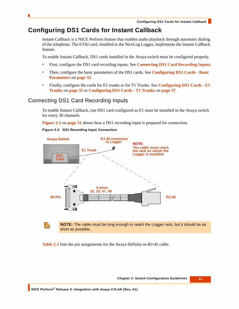
To enable Instant Callback, one DS1 card configured as E1 must be installed in the Avaya switch for every 30 channels.
Figure 2-2 on page 31 shows how a DS1 recording input is prepared for connection.Figure 2-2 DS1 Recording Input Connection
Table 2-1 lists the pin assignments for the Avaya Definity-to-RJ-45 cable.
NOTE: The cable must be long enough to reach the Logger rack, but it should be as short as possible.
DS1Card
RJ-45 connector
E1 Trunk
to LoggerAvaya Switch
RJ-4550-Pin
4 wires22, 23, 47, 48
The cable must reachthe rack on which theLogger is installed
NOTE:
31 Chapter 2: Switch Configuration Guidelines
NICE Perform® Release 3: Integration with Avaya CVLAN (Rev. A1)

Configuring DS1 Cards for Instant Callback
Table 2-1: Avaya Definity-to-RJ-45 cable Pin Assignments
Configuring DS1 Cards - Basic Parameters
To configure the DS1 card basic parameters:
1. At the Avaya Communication Manager Administration Terminal command prompt, type display ds1 slot# and press Enter.
The DS1 Circuit Pack screen appears (in view-mode).Figure 2-3 DS1 Circuit Pack - View Mode
2. Type the command change ds1 slot # and press Enter.
The DS1 Circuit Pack screen appears (in change-mode).
DSI Card (50-Pin Amphenol) RJ-45
23 (LO high side) 1
48 (LO) 2
22 (LI) 4
47 (LI high side) 5
N/C 3-8
TIP: The slot # is the identity number of the slot in which the DS1 card is installed in the switch. It is comprised of the cabinet # - shelf # - slot #Example: 01c12 = cabinet 01, shelf c and slot 12
32 Chapter 2: Switch Configuration Guidelines
NICE Perform® Release 3: Integration with Avaya CVLAN (Rev. A1)

Configuring DS1 Cards for Instant Callback
Figure 2-4 DS1 Circuit Pack - Change Mode
3. Define the parameter values as listed in Table 2-2.
4. At the Avaya Communication Manager Administration Terminal command prompt, type display port port# and press Enter.
The station number appears.
5. Type the command display station xxxx (where xxxx is the station you want to check). The station information appears.
IMPORTANTThese parameters apply to E1 trunks with a DS1 bit rate of 2 MB.
TIP: The port # is the identity number of the port in the DS1. It is comprised of the cabinet # - shelf # - slot # - port #.Example: 01c1201 = cabinet 01, shelf c, slot 12 port 01
33 Chapter 2: Switch Configuration Guidelines
NICE Perform® Release 3: Integration with Avaya CVLAN (Rev. A1)
Configuring DS1 Cards for Instant Callback
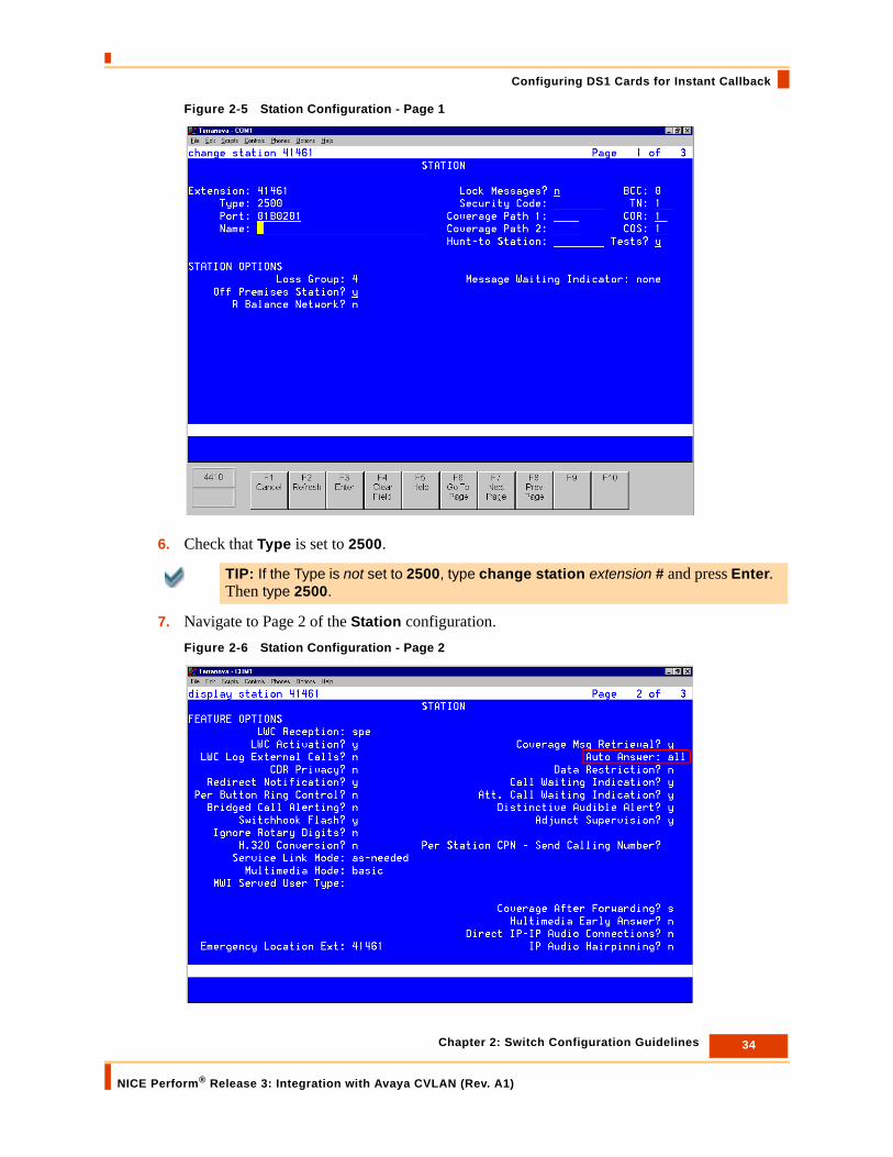
Figure 2-5 Station Configuration - Page 1
6. Check that Type is set to 2500.
7. Navigate to Page 2 of the Station configuration.Figure 2-6 Station Configuration - Page 2
TIP: If the Type is not set to 2500, type change station extension # and press Enter. Then type 2500.
34 Chapter 2: Switch Configuration Guidelines
NICE Perform® Release 3: Integration with Avaya CVLAN (Rev. A1)
Configuring DS1 Cards for Instant Callback
8. Check that Auto Answer is set to All.
Configuring DS1 Cards - E1 Trunks
The configuration is different for E1 trunks (see procedure below) and T1 trunks (see page 35).
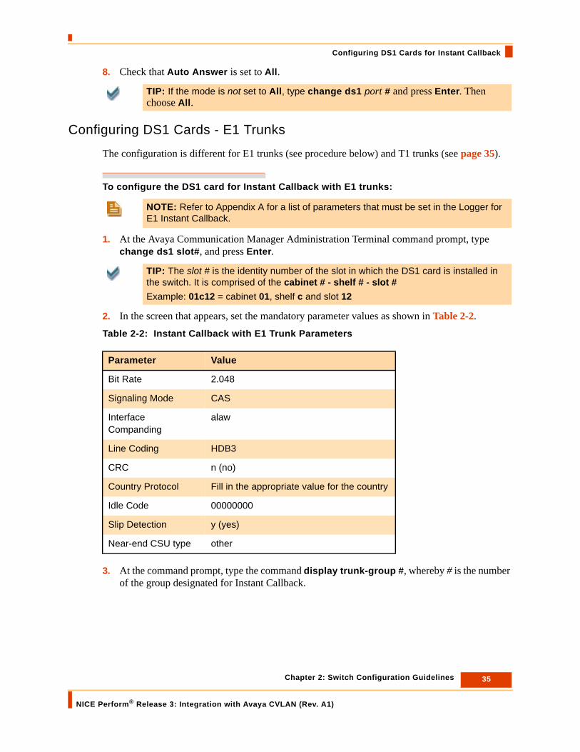
To configure the DS1 card for Instant Callback with E1 trunks:
1. At the Avaya Communication Manager Administration Terminal command prompt, type change ds1 slot#, and press Enter.
2. In the screen that appears, set the mandatory parameter values as shown in Table 2-2.
Table 2-2: Instant Callback with E1 Trunk Parameters
3. At the command prompt, type the command display trunk-group #, whereby # is the number of the group designated for Instant Callback.
TIP: If the mode is not set to All, type change ds1 port # and press Enter. Then choose All.
NOTE: Refer to Appendix A for a list of parameters that must be set in the Logger for E1 Instant Callback.
TIP: The slot # is the identity number of the slot in which the DS1 card is installed in the switch. It is comprised of the cabinet # - shelf # - slot #Example: 01c12 = cabinet 01, shelf c and slot 12
Parameter Value
Bit Rate 2.048
Signaling Mode CAS
Interface Companding
alaw
Line Coding HDB3
CRC n (no)
Country Protocol Fill in the appropriate value for the country
Idle Code 00000000
Slip Detection y (yes)
Near-end CSU type other
35 Chapter 2: Switch Configuration Guidelines
NICE Perform® Release 3: Integration with Avaya CVLAN (Rev. A1)

Configuring DS1 Cards for Instant Callback
4. In the screen that appears, specify the parameter values as listed in Table 2-3, and Table 2-4.
Table 2-3: Trunk Group Configuration Parameters
Table 2-4: Trunk Parameter Configuration
Parameter Value
Direction Incoming
Dial Access? y
Queue Length 0
Comm Type voice
COR Fill in the appropriate Class or Restriction value for the site
Outgoing Display n
Busy Threshold 99
Auth Code n
Trunk Flash? n
CDR Reports n
TN 1
TAC Fill in the value required by the site
Parameter Value
Trunk Type (in/out) wink/wink
Outgoing Dial Type tone
Connected to Toll? n
Incoming Dial Tone y
Disconnect Supervision? In - y; Out -n
Answer Supervision Timeout 0
Incoming Rotary Timeout 0
Incoming Rotary Timeout (2) 5
Disconnect Timing (msec) 500
Sig Bit Version none
STT Loss normal
DTT to DCO Loss normal
Receive Answer Supervision y
36 Chapter 2: Switch Configuration Guidelines
NICE Perform® Release 3: Integration with Avaya CVLAN (Rev. A1)

Configuring DS1 Cards for Instant Callback
5. Navigate to Page 2 of the same series, and specify the parameter values as listed in Table 2-5.
Table 2-5: Trunk Group Configuration
Configuring DS1 Cards - T1 Trunks
The configuration is different for E1 trunks (see page 35) and T1 trunks (see below).
To configure the DS1 card for Instant Callback with T1 trunks:
1. At the Avaya Communication Manager Administration Terminal command prompt, type change ds1 slot# and press Enter.
Parameter Value
ACA Assignment n
Used for DCS n
Suppress # Outpulsing n
Seize When Maintenance Busy Neither ens
Incoming Tone (DTMF) ANI n
Connected to CO n
Measured none
Internal Alert n
Data Restriction n
Maintenance Tests n
NOTE: For T1 Instant Callback, only D4-AMI frame format is supported.Refer to Appendix A for a list of parameters that must be set in the Logger for T1 Instant Callback.
TIP: The slot # is the identity number of the slot in which the DS1 card is installed in the switch. It is comprised of the cabinet # - shelf # - slot #Example: 01c12 = cabinet 01, shelf c and slot 12.
37 Chapter 2: Switch Configuration Guidelines
NICE Perform® Release 3: Integration with Avaya CVLAN (Rev. A1)

Configuring DS1 Cards for Instant Callback
2. In the screen that appears, specify the parameter values listed in Table 2-6.
Table 2-6: Instant Callback with T1 Trunk Parameters
3. At the command prompt, type the command display trunk-group #, whereby # is the number of the group designated for Instant Callback.
Parameter Value
Bit Rate 1.544
Line Compensation 1
Signaling Mode robbed bit
Interface Companding mulaw
Line Coding ami-basic or b8zs
Framing Mode d4 or esf
Idle Code 1111111
Slip Detection n (no)
Near end CSU type other
38 Chapter 2: Switch Configuration Guidelines
NICE Perform® Release 3: Integration with Avaya CVLAN (Rev. A1)

Configuring DS1 Cards for Instant Callback
4. In the screen that appears, specify the parameter values listed in Table 2-7 and Table 2-8.
Table 2-7: Trunk Group Configuration Parameters
Parameter Value
Direction Incoming
Dial Access? y
Queue Length 0
Comm Type voice
COR Fill in the appropriate Class or Restriction value for the site
Outgoing Display n
Busy Threshold 99
Authority Code n
Trunk Flash? n
CDR Reports y
TN 1
TAC Fill in the value required by the site
39 Chapter 2: Switch Configuration Guidelines
NICE Perform® Release 3: Integration with Avaya CVLAN (Rev. A1)
Configuring DS1 Cards for Instant Callback
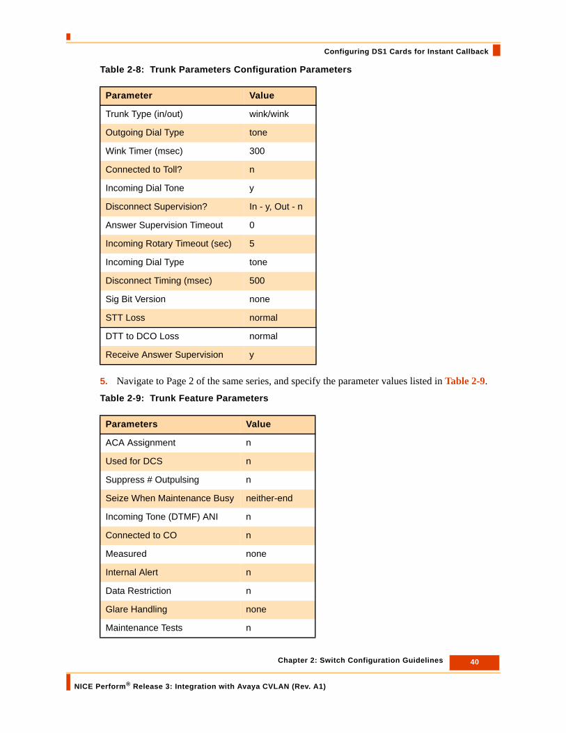
Table 2-8: Trunk Parameters Configuration Parameters
5. Navigate to Page 2 of the same series, and specify the parameter values listed in Table 2-9.
Table 2-9: Trunk Feature Parameters
Parameter Value
Trunk Type (in/out) wink/wink
Outgoing Dial Type tone
Wink Timer (msec) 300
Connected to Toll? n
Incoming Dial Tone y
Disconnect Supervision? In - y, Out - n
Answer Supervision Timeout 0
Incoming Rotary Timeout (sec) 5
Incoming Dial Type tone
Disconnect Timing (msec) 500
Sig Bit Version none
STT Loss normal
DTT to DCO Loss normal
Receive Answer Supervision y
Parameters Value
ACA Assignment n
Used for DCS n
Suppress # Outpulsing n
Seize When Maintenance Busy neither-end
Incoming Tone (DTMF) ANI n
Connected to CO n
Measured none
Internal Alert n
Data Restriction n
Glare Handling none
Maintenance Tests n
40 Chapter 2: Switch Configuration Guidelines
NICE Perform® Release 3: Integration with Avaya CVLAN (Rev. A1)

Configuring DS1 Cards for Instant Callback
6. Navigate to Page 3 of the same series, and specify the parameter values listed in Table 2-10, Table 2-11 and Table 2-12.
Table 2-10: Administer Timers Parameters
Table 2-11: End to End Signal Parameters
Table 2-12: Outpulsing Information Parameters
Parameter Value
Incoming Disconnect 500
Incoming Dial Guard 70
Incoming Glare Guard 1500
Programmed Dial Pause 1500
Flash Length 540
Outgoing Disconnect 500
Outgoing Dial Guard 1600
Outgoing Glare Guard 1500
Outgoing Seizure Response 5
Disconnect Signal Error 240
Incoming Incomplete Dial Alarm 255
Parameter Value
Tone 350
Pause 150
Parameter Value
PPS 10
Make 40
Break 60
41 Chapter 2: Switch Configuration Guidelines
NICE Perform® Release 3: Integration with Avaya CVLAN (Rev. A1)

Blank page for double-sided printing.
3
Preparing the Avaya Environment
This chapter describes the procedures for installing and configuring the Avaya CVLAN on the AES Server for use with NICE Perform Release 3.
.
Contents
Preparing the AES environment for CVLAN ................................................................44Configure the Switch on AES.....................................................................................44Define the CTI Link ....................................................................................................47Configure the CTI Link Connection ............................................................................47Verify the CTI Link......................................................................................................48
IMPORTANT An Avaya System Administrator is responsible for all procedures in the Avaya environment.All procedures in the Avaya environment are by recommendation only!
IMPORTANTYou must install and configure the Avaya CVLAN or AES Server before you install and configure the NICE Perform Integrations.
Chapter 3: Preparing the Avaya Environment
NICE Perform® Release 3: Integration with Avaya CVLAN (Rev. A1)
43

Preparing the AES environment for CVLAN
Preparing the AES environment for CVLAN
In an AES environment, the AES administrator must prepare the AES-CTI link connections. Below is a brief overview of the procedures that must be performed by the administrator.
Before you begin, make sure that you are using AES Version 3.0 or higher with the latest service pack.
Configure the Switch on AES
The administrator must define a switch via the OAM and in the Communication Manager Avaya Site Administration. The switch must be named and assigned an IP address and password. The password of the switch must be identical to the password assigned to the AES service in the Communication Manager. After the switch is configured, the administrator should verify that the AES-switch connection is active. Figure 3-1 OAM: Define and Configure the Switch
IMPORTANT An Avaya System Administrator is responsible for all procedures in the Avaya environment.All procedures in the Avaya environment are by recommendation only!
44 Chapter 3: Preparing the Avaya Environment
NICE Perform® Release 3: Integration with Avaya CVLAN (Rev. A1)
Preparing the AES environment for CVLAN
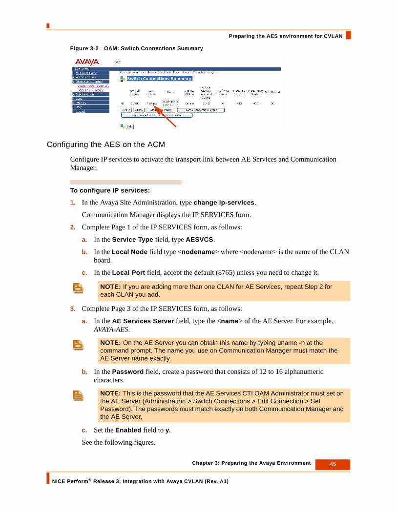
Figure 3-2 OAM: Switch Connections Summary
Configuring the AES on the ACM
Configure IP services to activate the transport link between AE Services and Communication Manager.
To configure IP services:
1. In the Avaya Site Administration, type change ip-services.
Communication Manager displays the IP SERVICES form.
2. Complete Page 1 of the IP SERVICES form, as follows:
a. In the Service Type field, type AESVCS.
b. In the Local Node field type <nodename> where <nodename> is the name of the CLAN board.
c. In the Local Port field, accept the default (8765) unless you need to change it.
3. Complete Page 3 of the IP SERVICES form, as follows:
a. In the AE Services Server field, type the <name> of the AE Server. For example, AVAYA-AES.
b. In the Password field, create a password that consists of 12 to 16 alphanumeric characters.
c. Set the Enabled field to y.
See the following figures.
NOTE: If you are adding more than one CLAN for AE Services, repeat Step 2 for each CLAN you add.
NOTE: On the AE Server you can obtain this name by typing uname -n at the command prompt. The name you use on Communication Manager must match the AE Server name exactly.
NOTE: This is the password that the AE Services CTI OAM Administrator must set on the AE Server (Administration > Switch Connections > Edit Connection > Set Password). The passwords must match exactly on both Communication Manager and the AE Server.
45 Chapter 3: Preparing the Avaya Environment
NICE Perform® Release 3: Integration with Avaya CVLAN (Rev. A1)

Preparing the AES environment for CVLAN
Figure 3-3 Configuring IP Services in Communication Manager (1)
Figure 3-4 Configuring IP Services in Communication Manager (2)
46 Chapter 3: Preparing the Avaya Environment
NICE Perform® Release 3: Integration with Avaya CVLAN (Rev. A1)

Preparing the AES environment for CVLAN
Define the CTI Link
A CTI link must be defined in the Communication Manager via the Avaya Site Administration.
For CVLAN, the link should be an ASAI-IP link.Figure 3-5 Communication Manager: Change CTI Link
Configure the CTI Link Connection
The administrator must configure a CTI link via the AES OAM Admin. The Switch CTI Link Number must be the same link number defined in the Communication Manager.
The client Signal must be used in the configuration of the integration driver.
The IP address of the NICE Interaction Center (where the driver is running) must be defined as a client.
Figure 3-6 OAM: Add CVLAN CTI Link
Must match the link used in the
Communication Manager
driver integration
Must match the link used in the
47 Chapter 3: Preparing the Avaya Environment
NICE Perform® Release 3: Integration with Avaya CVLAN (Rev. A1)

Preparing the AES environment for CVLAN
Figure 3-7 OAM: CVLAN Links: Define the IP Address of the NICE Interaction Center as a Client
Verify the CTI Link
After the CTI link is configured, the administrator should verify that the AES-CTI link connection is active and in a Talking state.
To verify the CTI link:
1. From the AES OAM Administration, select Status and Control > Switch Conn Summary > Per Service Connections Details.
2. Check the Connection State for the relevant AES-CTI link connection.Figure 3-8 OAM: Verify Talking State
Type the IP address of the NICE Interaction Center and click Add Client
48 Chapter 3: Preparing the Avaya Environment
NICE Perform® Release 3: Integration with Avaya CVLAN (Rev. A1)

Chapter 4: Integrating Avaya CVLAN with NICE Perform
NICE Perform® Release 3: Integration with Avaya CVLAN (Rev. A1)
49
4
Integrating Avaya CVLAN with NICE Perform
This chapter describes the procedures for integrating the Avaya CVLAN and AES Servers with NICE Perform Release 3.
Contents
Installing the CVLAN Client on the NICE Interaction Center ......................................50
Before You Begin the Integration..................................................................................52
Configuring the CTI Interface ........................................................................................54
Configuring the Connection Manager ..........................................................................66
Creating the Switch Driver.............................................................................................70
Installing the Switch Driver............................................................................................81
IMPORTANT You must install and configure the Avaya CVLAN or AES Server before you install and configure the NICE Perform integrations.

50 Chapter 4: Integrating Avaya CVLAN with NICE Perform
NICE Perform® Release 3: Integration with Avaya CVLAN (Rev. A1)
Installing the CVLAN Client on the NICE Interaction Center
Installing the CVLAN Client on the NICE Interaction Center
The CVLAN client must be installed on the NICE Interaction Center.
To install the CVLAN client:
1. Insert the CVLAN Client Installation CD into your CD drive.
2. Navigate to Avaya CM\Application Enablement CVLAN Service CTI and double click the setup.exe file to execute it. The CVLAN wizard Welcome window starts.Figure 4-1 CVLAN Wizard - Welcome
3. Click Next. The Choose Destination Location window appears.
IMPORTANT The AES CVLAN Client is installed regardless of which CVLAN Server is used. If you try and install another CVLAN Client, the integration will not run.The AES CVLAN Client must be version 3.1.x.
NOTE: It is recommended that an Avaya System Administrator be present during the installation to assist with this phase of the installation.

51 Chapter 4: Integrating Avaya CVLAN with NICE Perform
NICE Perform® Release 3: Integration with Avaya CVLAN (Rev. A1)
Installing the CVLAN Client on the NICE Interaction Center
Figure 4-2 CVLAN Wizard - Choose Destination Location
4. Select the appropriate destination folder and then click Next. The CVLAN client is installed and the following window appears.Figure 4-3 CVLAN Wizard - Question
5. Click Yes/No, as required. The Installation Complete window appears.Figure 4-4 CVLAN Wizard - Installation Complete
6. Click Finish. The CVLAN client installation is complete.

52 Chapter 4: Integrating Avaya CVLAN with NICE Perform
NICE Perform® Release 3: Integration with Avaya CVLAN (Rev. A1)
Before You Begin the Integration
Before You Begin the IntegrationCVLAN Server
Before installing the switch driver, refer to Preparing the Avaya Environment on page 43.
CVLAN Client
CVLAN Client should be AES 3.1.x (refer to Installing the CVLAN Client on the NICE Interaction Center on page 50).
Configuration Information
To configure the NICE Perform Integrations, you run a series of configuration wizards. Each configuration wizard requires you to enter some information.
Before running the configurations wizards, you must obtain the necessary information for each of the following configuration wizards:
CTI Interface Configuration
The CTI Interface defines the actual CTI server to which the system will integrate. For every Interface, a switch is configured. This is the physical server on which the Interface is installed. More than one Interface may be installed on the same switch, so when configuring the Interface, the correct switch must be defined.
Before proceeding with Configuring the CTI Interface on page 54, have ready the following information:
• CVLAN Server IP Number
• Signal Number
• The NICE Interaction Center IP is defined as a client in the CVLAN Administration.
• CVLAN Server and the NICE Interaction Center are on the same segment on the LAN.
• If free seating environment or Agent ID information is needed: Expert Agent Selection (EAS) software is installed on the switch. This is needed even for simple agent login into the PBX.
• Ensure you have the following information:
• Stations
• ACDs
• VDNs
• IVR numbers

53 Chapter 4: Integrating Avaya CVLAN with NICE Perform
NICE Perform® Release 3: Integration with Avaya CVLAN (Rev. A1)
Before You Begin the Integration
Connection Manager Configuration
The Connection Manager is used for creating and maintaining the CTI link. The connection manager is used as a pipeline for transferring information between the Interface and the driver/s once the link is established. One Connection Manager can be used to connect to several Interfaces and can have several drivers.
Before proceeding with Configuring the Connection Manager on page 66, have ready the IP address or Host Name where the Connection Manager is installed.
Switch Driver Configuration
The driver is used to get the actual events from the Interface via the Connection Manager. When the driver receives these events, they are filtered and translated into CAPI commands (start call, end call) or discarded, according to the system configuration (recording rules, CTI analysis installed, and so on).
Before proceeding with Creating the Switch Driver on page 70, have ready the IP address or Host Name where the Switch Driver is installed.
SNMP Service
Before installing the switch driver make sure that the SNMP Service is installed on your computer.
54 Chapter 4: Integrating Avaya CVLAN with NICE Perform
NICE Perform® Release 3: Integration with Avaya CVLAN (Rev. A1)
Configuring the CTI Interface
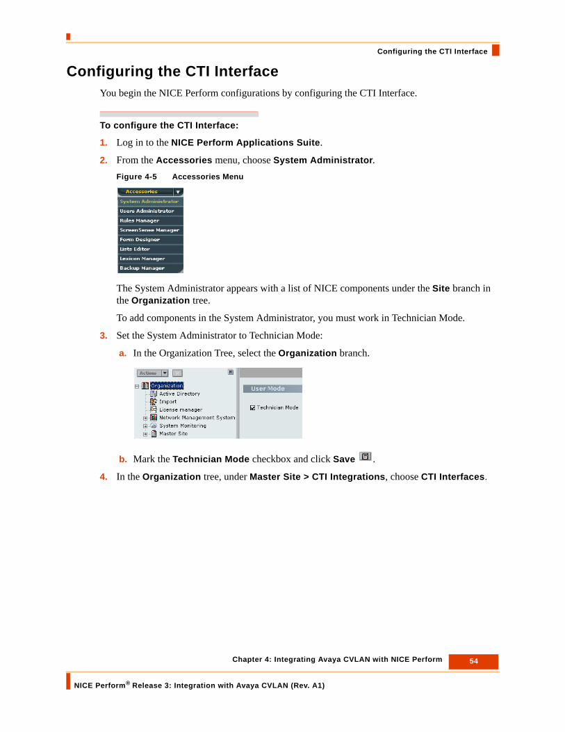
Configuring the CTI InterfaceYou begin the NICE Perform configurations by configuring the CTI Interface.
To configure the CTI Interface:
1. Log in to the NICE Perform Applications Suite.
2. From the Accessories menu, choose System Administrator.Figure 4-5 Accessories Menu
The System Administrator appears with a list of NICE components under the Site branch in the Organization tree.
To add components in the System Administrator, you must work in Technician Mode.
3. Set the System Administrator to Technician Mode:
a. In the Organization Tree, select the Organization branch.
b. Mark the Technician Mode checkbox and click Save .
4. In the Organization tree, under Master Site > CTI Integrations, choose CTI Interfaces.

55 Chapter 4: Integrating Avaya CVLAN with NICE Perform
NICE Perform® Release 3: Integration with Avaya CVLAN (Rev. A1)
Configuring the CTI Interface
Figure 4-6 CTI Interfaces
5. From the Actions menu, choose New CTI Interface.Figure 4-7 Actions Menu
The Set New CTI Interface Wizard starts.

56 Chapter 4: Integrating Avaya CVLAN with NICE Perform
NICE Perform® Release 3: Integration with Avaya CVLAN (Rev. A1)
Configuring the CTI Interface
Figure 4-8 Introduction Window
6. Click Next.
The General Interface Information window appears.Figure 4-9 General Interface Information Window
7. To set the CTI Interface:
a. From the Telephony switch drop-down list, choose Avaya CM.
b. From the CTI Interface drop-down list, choose CVLAN.

57 Chapter 4: Integrating Avaya CVLAN with NICE Perform
NICE Perform® Release 3: Integration with Avaya CVLAN (Rev. A1)
Configuring the CTI Interface
c. Click Apply.
The Name and Physical Switch fields become enabled and the Create button appears.Figure 4-10 General Interface Information Window
8. In the Name field, type a name for the interface.
• To create a new physical switch, continue with step number 9.
• To use an existing switch, continue with step number 13.
9. Click the Create button.
The New Physical Switch window appears.Figure 4-11 New Physical Switch Window
Create Button

58 Chapter 4: Integrating Avaya CVLAN with NICE Perform
NICE Perform® Release 3: Integration with Avaya CVLAN (Rev. A1)
Configuring the CTI Interface
10. To create a New Physical Switch:
• In the Switch Name field, type a name for the switch.
• In the Physical Switch ID field, enter a switch ID.
• In the CLS Reporting Type field, choose CTI.
11. To enable non-standard CLS login options, mark the following checkboxes:
• To the same station again - allows agents to log in to the same workstation more than once.
• To more than one station - allows agents to log in to more than one workstation.
• To a station another agent is logged into - allows more than one agent to log in to one workstation.
12. Click OK.
The General Interface Information window reappears.
13. Choose a switch from the Physical Switch drop-down list and click Next.
The Switch Connection and Additional Information window appears.Figure 4-12 Switch Connection and Additional Information Window
14. Click the Expand arrow to expand the Switch Connection Details row.
NOTE: It is recommended to mark all three Agent Logon Modes.
Click to expand
59 Chapter 4: Integrating Avaya CVLAN with NICE Perform
NICE Perform® Release 3: Integration with Avaya CVLAN (Rev. A1)
Configuring the CTI Interface
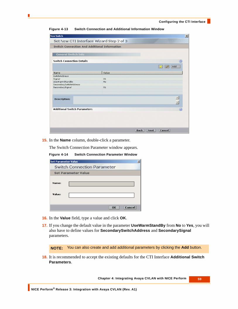
Figure 4-13 Switch Connection and Additional Information Window
15. In the Name column, double-click a parameter.
The Switch Connection Parameter window appears.Figure 4-14 Switch Connection Parameter Window
16. In the Value field, type a value and click OK.
17. If you change the default value in the parameter UseWarmStandBy from No to Yes, you will also have to define values for SecondarySwitchAddress and SecondarySignal parameters.
18. It is recommended to accept the existing defaults for the CTI Interface Additional Switch Parameters.
NOTE: You can also create and add additional parameters by clicking the Add button.

60 Chapter 4: Integrating Avaya CVLAN with NICE Perform
NICE Perform® Release 3: Integration with Avaya CVLAN (Rev. A1)
Configuring the CTI Interface
If you need to define existing parameters or to create new ones, see CTI Interface - Additional Switch Parameters on page 134.
19. Click Next.
The Switch Devices Configuration window appears.Figure 4-15 Switch Devices Configuration Window
20. Click the arrow to expand Available Devices.

61 Chapter 4: Integrating Avaya CVLAN with NICE Perform
NICE Perform® Release 3: Integration with Avaya CVLAN (Rev. A1)
Configuring the CTI Interface
Figure 4-16 Switch Devices Configuration Window
• To add a single device, continue with steps number 21 to 24.
• To add a range of devices, continue with steps number 25 to 27.
21. To add a single device, click the Add button.
The Available Device window appears.
NOTE: You can also add devices from existing .txt files using the Import button. For details see Importing Text Files on page 136.

62 Chapter 4: Integrating Avaya CVLAN with NICE Perform
NICE Perform® Release 3: Integration with Avaya CVLAN (Rev. A1)
Configuring the CTI Interface
Figure 4-17 Available Device Window
22. In the Device Number field, enter the number you want to assign to the device.
23. From the Device Type drop-down list, choose a device. The devices supported by the Avaya Communication Manager and Media Server switch are:
• Extension
• ACD (hunt group)
• VDN
• IVR
24. Click OK.
The Switch Devices Configuration window reappears.
NOTE: • When monitoring the IVR, you will receive IVR records. These records are not
usually needed. If you do not want to receive additional IVR records, do not choose this option.
• If you do not monitor the IVR, you will receive wrong directions in the following scenario:A Customer calls the IVR. The IVR blind transfers the Customer to an Agent. The call between the Customer and the Agent will receive the direction outgoing, instead of incoming.
63 Chapter 4: Integrating Avaya CVLAN with NICE Perform
NICE Perform® Release 3: Integration with Avaya CVLAN (Rev. A1)
Configuring the CTI Interface
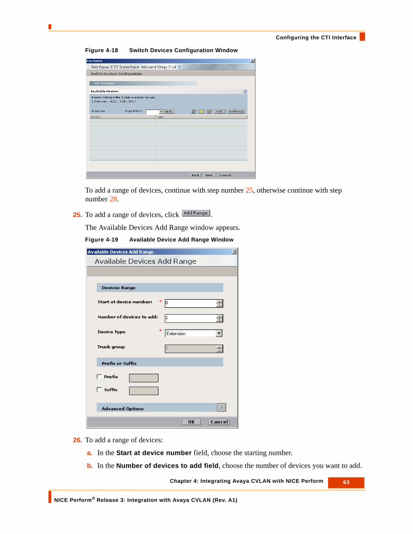
Figure 4-18 Switch Devices Configuration Window
To add a range of devices, continue with step number 25, otherwise continue with step number 28.
25. To add a range of devices, click .
The Available Devices Add Range window appears.Figure 4-19 Available Device Add Range Window
26. To add a range of devices:
a. In the Start at device number field, choose the starting number.
b. In the Number of devices to add field, choose the number of devices you want to add.

64 Chapter 4: Integrating Avaya CVLAN with NICE Perform
NICE Perform® Release 3: Integration with Avaya CVLAN (Rev. A1)
Configuring the CTI Interface
c. From the Device Type drop-down list, choose a device. The devices supported by the Avaya Communication Manager and Media Server switch are:
• Extension
• ACD
• VDN
• IVR
27. Click OK.
The Switch Devices Configuration window reappears.
28. Click Next.
29. The Summary window appears.Figure 4-20 Summary Window
NOTE: • When monitoring the IVR, you will receive IVR records. These records are not
usually needed. If you do not want to receive additional IVR records, do not choose this option.
• If you do not monitor the IVR, you will receive wrong directions in the following scenario:A Customer calls the IVR. The IVR blind transfers the Customer to an Agent. The call between the Customer and the Agent will receive the direction outgoing, instead of incoming.

65 Chapter 4: Integrating Avaya CVLAN with NICE Perform
NICE Perform® Release 3: Integration with Avaya CVLAN (Rev. A1)
Configuring the CTI Interface
The Summary window displays the CTI Interface name and ID, and the switch type that you defined.
30. Click Finish to create the CTI Interface.
The System Administrator page reappears. Confirm the new CTI Interface appears in the list of CTI interfaces.Figure 4-21 System Administrator Window
NOTE: For details pertaining to maintaining or changing the CTI Interface or any of its definitions, refer to the NICE Perform System Administrator’s Guide.
66 Chapter 4: Integrating Avaya CVLAN with NICE Perform
NICE Perform® Release 3: Integration with Avaya CVLAN (Rev. A1)
Configuring the Connection Manager
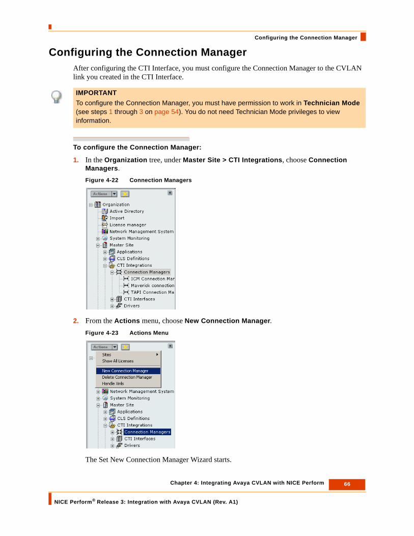
Configuring the Connection ManagerAfter configuring the CTI Interface, you must configure the Connection Manager to the CVLAN link you created in the CTI Interface.
To configure the Connection Manager:
1. In the Organization tree, under Master Site > CTI Integrations, choose Connection Managers.
Figure 4-22 Connection Managers
2. From the Actions menu, choose New Connection Manager.Figure 4-23 Actions Menu
The Set New Connection Manager Wizard starts.
IMPORTANTTo configure the Connection Manager, you must have permission to work in Technician Mode (see steps 1 through 3 on page 54). You do not need Technician Mode privileges to view information.

67 Chapter 4: Integrating Avaya CVLAN with NICE Perform
NICE Perform® Release 3: Integration with Avaya CVLAN (Rev. A1)
Configuring the Connection Manager
Figure 4-24 Introduction Window
3. Click Next.
The General Information window appears.Figure 4-25 General Information Window

68 Chapter 4: Integrating Avaya CVLAN with NICE Perform
NICE Perform® Release 3: Integration with Avaya CVLAN (Rev. A1)
Configuring the Connection Manager
4. In the Name field type a name for the Connection Manager.
5. Accept the default port number 62094.
6. In the ID field enter the ID number you want to give to the Connection Manager.
7. In the Location area, select either the IP Address or the Host Name of the computer on which the Connection Manager is located and type in the relevant values.
8. It is recommended to accept the existing defaults for the Connection Manager Reporting Levels. If you need to make changes, see Reporting Levels on page 138.
9. It is recommended to accept the existing defaults for the Connection Manager Additional Parameters. If you need to define existing parameters or to create new ones, see Connection Manager - Additional Parameters on page 141.
10. Click Next.
The Connection Manager Switches window appears.Figure 4-26 Connection Manager Switches Window
All available CTI Interfaces are listed in the Available Interfaces area.
11. Select the Interface(s) you want to attach and click the arrow to transfer the Interface(s) to the Attached Interfaces area.
12. It is recommended to accept the existing defaults for the Configure Connection Manager - Interface Parameters.
If you need to define existing parameters or to create new ones, see Connection Manager - Interface Parameters on page 143.
13. Click Next.
The Summary window appears.

69 Chapter 4: Integrating Avaya CVLAN with NICE Perform
NICE Perform® Release 3: Integration with Avaya CVLAN (Rev. A1)
Configuring the Connection Manager
Figure 4-27 Summary Window
14. The Summary window displays the Connection Manager name and ID. Click Finish to create the Connection Manager.
The System Administrator page reappears and the new Connection Manager appears in the list of Connection Managers.
NOTE: For details pertaining to maintaining or changing the Connection Manager or any of its definitions, refer to the NICE Perform System Administrator’s Guide.

70 Chapter 4: Integrating Avaya CVLAN with NICE Perform
NICE Perform® Release 3: Integration with Avaya CVLAN (Rev. A1)
Creating the Switch Driver
Creating the Switch DriverAfter configuring the Connection Manager, you create the switch driver and connect it to the Connection Manager.
To create the switch driver:
1. In the Organization tree, under Master Site > CTI Integrations, choose Drivers.
Figure 4-28 Drivers
IMPORTANTTo create the Switch Driver, you must have permission to work in Technician Mode (see steps 1 through 3 on page 54). You do not need Technician Mode privileges to view information.

71 Chapter 4: Integrating Avaya CVLAN with NICE Perform
NICE Perform® Release 3: Integration with Avaya CVLAN (Rev. A1)
Creating the Switch Driver
2. From the Actions menu, choose New Driver.Figure 4-29 Actions Menu
The Set New Driver Wizard starts.Figure 4-30 Introduction Window
3. Click Next.
The General Information window appears.

72 Chapter 4: Integrating Avaya CVLAN with NICE Perform
NICE Perform® Release 3: Integration with Avaya CVLAN (Rev. A1)
Creating the Switch Driver
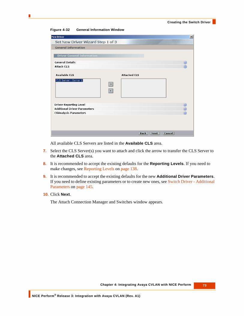
Figure 4-31 General Information Window
4. In the Name field type the name you want to give to the switch driver.
In the ID field enter the ID number you want to give to the switch driver.
5. In the Driver’s Location area, select either the IP Address or the Host Name of the computer on which the NICE Integrations are installed.
6. Click to expand the Attach CLS row.
73 Chapter 4: Integrating Avaya CVLAN with NICE Perform
NICE Perform® Release 3: Integration with Avaya CVLAN (Rev. A1)
Creating the Switch Driver
Figure 4-32 General Information Window
All available CLS Servers are listed in the Available CLS area.
7. Select the CLS Server(s) you want to attach and click the arrow to transfer the CLS Server to the Attached CLS area.
8. It is recommended to accept the existing defaults for the Reporting Levels. If you need to make changes, see Reporting Levels on page 138.
9. It is recommended to accept the existing defaults for the new Additional Driver Parameters. If you need to define existing parameters or to create new ones, see Switch Driver - Additional Parameters on page 145.
10. Click Next.
The Attach Connection Manager and Switches window appears.

74 Chapter 4: Integrating Avaya CVLAN with NICE Perform
NICE Perform® Release 3: Integration with Avaya CVLAN (Rev. A1)
Creating the Switch Driver
Figure 4-33 Attach Connection Manager and Switches Window
11. Mark the checkbox for the CTI Interface you want to attach to this driver.
12. Double-click the CTI Interface you want to attach to this driver.
NOTE: When you mark the checkbox for the CTI Interface, the checkbox for the corresponding Connection Manager automatically becomes marked as well. You cannot mark the checkbox of the Connection Manager by itself.
Mark checkbox for the CTI Interface

75 Chapter 4: Integrating Avaya CVLAN with NICE Perform
NICE Perform® Release 3: Integration with Avaya CVLAN (Rev. A1)
Creating the Switch Driver
The Driver - Interface Configuration window appears.Figure 4-34 Driver - Interface Configuration Window
13. To define Device Mapping and/or Rejected Devices, you must first define them in the Driver Real Time Plugins window. Expand the Driver Real-Time Plugins row.
The Driver Real-Time Plugins window appears.Figure 4-35 Driver Real-Time Plugins Window

76 Chapter 4: Integrating Avaya CVLAN with NICE Perform
NICE Perform® Release 3: Integration with Avaya CVLAN (Rev. A1)
Creating the Switch Driver
a. To define Device Mapping, mark DeviceMapping.
b. To define Rejected Devices, mark RejectedDevices.
14. Expand the Monitor Devices row.Figure 4-36 Monitor Devices Window
All available devices are listed in the Available Devices area.
15. Select the device(s) you want to monitor and click the arrow to transfer the device(s) to the Monitored Devices area.
16. If you do not want to define Device Mapping and/or Rejected Devices, continue with step 26.
17. If you want to define Device Mapping and/or Rejected Devices, continue with step number 18.
18. If you marked Device Mapping, expand the Device Mapping row.
The Devices Mapping window appears.

77 Chapter 4: Integrating Avaya CVLAN with NICE Perform
NICE Perform® Release 3: Integration with Avaya CVLAN (Rev. A1)
Creating the Switch Driver
Figure 4-37 Devices Mapping Window
• To add a single device, continue with step number 19.
• To add a range of devices, continue with steps number 21 to 26.
19. To add a single device, click the Add button.
The Device Mapping - Add window appears.Figure 4-38 Device Mapping - Add Window
a. In the Map From Device field, enter the device number you want to map from.
b. In the Map To Device field, enter the device number you want to map to.
c. Click OK.
20. To add a range of devices, continue with step 21, otherwise continue with step 26.
21. To add a range of devices, click .
NOTE: You can also add devices from existing .txt files using the Import button. For details see Importing Text Files on page 136.

78 Chapter 4: Integrating Avaya CVLAN with NICE Perform
NICE Perform® Release 3: Integration with Avaya CVLAN (Rev. A1)
Creating the Switch Driver
The Device Mapping - Add Range window appears.Figure 4-39 Device Mapping - Add Range Window
a. Enter a value in the Start ‘Map From’ Device field.
b. Enter a value in the Number of devices to be mapped field.
c. Enter a value in the Start ‘Map To’ Device field.
d. Click OK.
22. If you marked the Rejected Devices, expand the Rejected Devices row, otherwise procede to step 27.
The Rejected Devices window appears.Figure 4-40 Rejected Devices Window
• To define a single device you do not want to record, continue with step number 23.

79 Chapter 4: Integrating Avaya CVLAN with NICE Perform
NICE Perform® Release 3: Integration with Avaya CVLAN (Rev. A1)
Creating the Switch Driver
• To define a range of devices you do not want to record, continue with steps number 24 to 26.
23. To define a single device you do not want to record, click the Add button.
The Rejected Device - Add window appears.Figure 4-41 Rejected Device - Add Window
a. In the Device field, enter the device number you do not want to record.
b. Click OK.
To define a range of devices you do not want to record, continue with step 24, otherwise continue with step 26.
24. To define a range of devices you do not want to record, click .
The Rejected Devices - Add Range window appears.Figure 4-42 Rejected Devices - Add Range Window
a. Enter a value in the Start at device number field.
b. Enter a value in the Number of devices to add field.
c. Click OK.
25. It is recommended to accept the existing defaults for the Additional Driver Switch Parameters. If it is necessary to define existing parameters or to create new ones, see Driver Interface - Additional Parameters on page 147.
26. Click OK.
The Attach Connection Manager and Switches window reappears.
27. Click Next.
The Summary window appears.
NOTE: You can also add devices from existing .txt files using the Import button. For details see Importing Text Files on page 136.

80 Chapter 4: Integrating Avaya CVLAN with NICE Perform
NICE Perform® Release 3: Integration with Avaya CVLAN (Rev. A1)
Creating the Switch Driver
Figure 4-43 Summary Window
The Summary window displays the switch driver name and ID.
28. Click Finish to create the new switch driver.
The System Administrator page reappears and the new switch driver appears in the list of switch drivers.
NOTE: For details pertaining to maintaining or changing the switch driver or any of its definitions, refer to the NICE Perform System Administrator’s Guide.

81 Chapter 4: Integrating Avaya CVLAN with NICE Perform
NICE Perform® Release 3: Integration with Avaya CVLAN (Rev. A1)
Installing the Switch Driver
Installing the Switch DriverAfter performing all the above configurations, you now install the switch driver on the NICE Interactions Center server.
To install the switch driver:
1. Insert the NICE Perform CTI Integration Suite Installation CD in the CD-ROM drive.
2. Navigate to the Switch Driver installation program and double-click Setup.exe.
The NICE Perform CTI Wizard starts.Figure 4-44 NICE Perform CTI - InstallShield Welcome Window
3. Click Next.
The Choose Destination Location window appears.
NOTE: It is preferable to install the switch driver now and NOT before the configuration.

82 Chapter 4: Integrating Avaya CVLAN with NICE Perform
NICE Perform® Release 3: Integration with Avaya CVLAN (Rev. A1)
Installing the Switch Driver
Figure 4-45 Choose Destination Location Window
4. Accept the default path, or, if you want to change the folder in which you want to install the integration files, click Browse, and navigate to the desired folder.
5. Click Next. The Select Integrations window appears. Figure 4-46 Select Integrations Window
6. Expand Avaya CM, then mark CVLAN.
Mark CVLAN
Expand Avaya CM
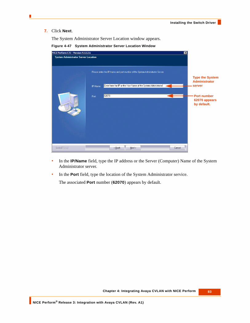
83 Chapter 4: Integrating Avaya CVLAN with NICE Perform
NICE Perform® Release 3: Integration with Avaya CVLAN (Rev. A1)
Installing the Switch Driver
7. Click Next.
The System Administrator Server Location window appears.Figure 4-47 System Administrator Server Location Window
• In the IP/Name field, type the IP address or the Server (Computer) Name of the System Administrator server.
• In the Port field, type the location of the System Administrator service.
The associated Port number (62070) appears by default.
Type the System Administrator server
Port number 62070 appears by default.

84 Chapter 4: Integrating Avaya CVLAN with NICE Perform
NICE Perform® Release 3: Integration with Avaya CVLAN (Rev. A1)
Installing the Switch Driver
8. Click Next.
The Setup Type window appears.Figure 4-48 Setup Type Window
9. If your site is configured for network user account, leave the default setting, Network User Account, and continue with Step 11.
10. If you need to configure for a local system account, select Local System Account and continue with Step 19 on page 87.
11. Click Next.
Select the relevant system account

85 Chapter 4: Integrating Avaya CVLAN with NICE Perform
NICE Perform® Release 3: Integration with Avaya CVLAN (Rev. A1)
Installing the Switch Driver
The Network User Account setup window appears.Figure 4-49 Network User Account Setup Window
• To define an existing network user, continue with Step 12.
• If no user exists or to add an additional new user, continue with Step 18.
12. In the User name area, click Browse.
The Browse for a User Account window appears.Figure 4-50 Browse for a User Account Window
13. In the Domain or server area, click Browse.

86 Chapter 4: Integrating Avaya CVLAN with NICE Perform
NICE Perform® Release 3: Integration with Avaya CVLAN (Rev. A1)
Installing the Switch Driver
The Select a Domain or Server window appears.Figure 4-51 Select a Domain or Server Window
14. Select a domain or server, and click OK.
15. In the Browse for a User Account window (see Figure 4-50), in the User name area, click Browse.
The Select a User Name window appears.Figure 4-52 Select a User Name Window
16. Select a user name, and click OK.
The Network User Account setup window reappears.
17. In the Network User Account setup window, in the Password field, type the password provided by the site administrator.
18. If no user exists or to add an additional new user, click New User.

87 Chapter 4: Integrating Avaya CVLAN with NICE Perform
NICE Perform® Release 3: Integration with Avaya CVLAN (Rev. A1)
Installing the Switch Driver
The New User Information window appears.Figure 4-53 New User Information Window
• Complete all fields and click OK.
19. Click Next.
The Start Copying Files window appears.Figure 4-54 Start Copying Files Window
Verify that the list is correct.
20. Click Next.

88 Chapter 4: Integrating Avaya CVLAN with NICE Perform
NICE Perform® Release 3: Integration with Avaya CVLAN (Rev. A1)
Installing the Switch Driver
The Setup Status window appears as the installation program installs the switch driver.Figure 4-55 Setup Status Window
As part of the installation, the installation program automatically shuts down and then restarts the SNMP service.Figure 4-56 SNMP Service Message

89 Chapter 4: Integrating Avaya CVLAN with NICE Perform
NICE Perform® Release 3: Integration with Avaya CVLAN (Rev. A1)
Installing the Switch Driver
Upon completion, the InstallShield Wizard Complete window appears.Figure 4-57 InstallShield Wizard Complete Window
21. Click Finish. The Integration package is installed.

Blank page for double-sided printing.

5
Troubleshooting
This section provides troubleshooting scenarios and their solutions.
Contents
Open Case Procedure ....................................................................................................92
Missing Login/Logout Error...........................................................................................93
Missing VDN Information in Database..........................................................................94
Failed to Monitor Device ................................................................................................94
Open Connection Failure...............................................................................................95
Monitor End Event is Received .....................................................................................95
ISDN Trunk - Alerting Event...........................................................................................96
Calls Are Reported With The Wrong Direction ............................................................96
Connection Manager and Driver Fail to Connect to the AES .....................................97
AES Environment: General Troubleshooting Tips ......................................................98
TIP: If you need to send a problem to Customer Support at NICE, prepare all the necessary information. See Open Case Procedure on page 92.
Chapter 5: Troubleshooting
NICE Perform® Release 3: Integration with Avaya CVLAN (Rev. A1)
91

Open Case Procedure
Open Case ProcedureIf you need to send a problem to Customer Support at NICE, prepare the following information:
• The entire Integration folder compressed as a .zip file.
• Recording environment.
• Version of NICE Interaction Center plus current SP.
• Resources information (VDN, ACD, Station, Voice Mail and so on).
• A description of the problem and specific scenarios if relevant (including Call ID, scenario, time of call, the devices involved in the problematic scenario and so on).
• The output file generated by NICE Events Spy (see NICE Events Spy on page 102).
• Run the Debug Services and send the ctibinary.txt and ctitext.txt files for analysis (see NICE Debug Service on page 107.)
TIP: When sending the Nice Events Spy output file, the CTI_Logs and/or the Debug Service, it is recommended to activate the tool before restarting the driver. This will provide all traces and a more complete picture.
92 Chapter 5: Troubleshooting
NICE Perform® Release 3: Integration with Avaya CVLAN (Rev. A1)

Missing Login/Logout Error
Missing Login/Logout Error
Problem:
The CLS did not receive login or logout events from the agent in real-time.
Solution:
Monitor the ACD number (hunt group extension number).
Make sure the ACD number is configured under Available Devices. Refer to Creating the Switch Driver, Step 14.
IMPORTANTDuring startup, when the driver initializes, the driver queries the Call Server for monitored devices. For each device that is currently logged in to the switch, the driver creates a Login event. The driver sends these Login events to the Call Server. There are no corresponding Logout events for these Login events. This is the normal behavior of the driver.
93 Chapter 5: Troubleshooting
NICE Perform® Release 3: Integration with Avaya CVLAN (Rev. A1)

Missing VDN Information in Database
Missing VDN Information in Database
Problem
In the nice interactions database, the VDN column remains empty.
Solution
Add the VDN number to the monitored devices list.
To do this:
1. In the System Administrator, verify that you are working in Technician mode: In the Organization tree, click Organization. Then mark the Technician Mode checkbox and click Save.
2. In System Administrator, in the Organization tree, under Master Site > CTI Integrations, expand CTI Interfaces.
3. Select the relevant CTI Interface, and click the Devices tab.
4. Expand the Available Devices area, and click Add.
5. Add the VDN number.
6. Click OK and Save.
7. Check if the VDN information is reported in the Called Device field in the Delivered or Established events.
Refer to Creating the Switch Driver, Step 14.
Failed to Monitor Device
Problem:
A device was not monitored successfully.
Solution:
• Check the device configuration on the switch.
• Locate the error on the Connection Manager Log. This should provide you with an understanding of the error that occurred. The error is either reported with an associated cause or as an error number.
• Check that there are no other processes (other CTI Servers or applications) monitoring the device.
• Check that the device status on the switch is in-service.
94 Chapter 5: Troubleshooting
NICE Perform® Release 3: Integration with Avaya CVLAN (Rev. A1)

Open Connection Failure
Open Connection FailureProblem:
The Connection Manager cannot open a connection to the switch.
Solution:
(Start checking in the following order)
• Check the physical and network connections.
• Check if the CVLAN client and CVLAN Interface configured on the AES server exist.
• Check if the CVLAN Interface configured on the AES server is running.
• Check the ASAI-IP link.
• Locate the error on the Connection Manager Log. This should provide you with an understanding of the error that occurred. The error is either reported with an associated cause or as an error number.
Monitor End Event is ReceivedProblem:
The Monitor End event is received (Event Monitor End Received) when the CVLAN Interface configured on the AES server cannot receive events for a specific device. This usually indicates that a device was deleted in the switch or a CVLAN Interface configured on the AES server failure occurred.
Solution:
1. Check the device configuration in the switch.
2. Check that the CVLAN Interface configured on the AES server is running. To do this:
a. In the OAM, navigate to Status and Control > Switch Conn Summary.
b. Click Per Service Connection Details.
c. Check that the Connection State for the link is Talking.
95 Chapter 5: Troubleshooting
NICE Perform® Release 3: Integration with Avaya CVLAN (Rev. A1)
ISDN Trunk - Alerting Event
ISDN Trunk - Alerting EventProblem:
A trunk with PRI facility (ISDN Trunk), the Alerting Event will contain (#####).
Solution:
Once the call is connected, the value can be updated if the trunk or facility is properly administered.
Calls Are Reported With The Wrong DirectionProblem:
Calls are reported as Tandem or outgoing in the CallServer, although the calls are normal incoming calls from a customer to an agent.
Solution:
1. The parameter MaxLenOfInternalDevice from the Avaya TSAPI CTI Interface plug-in may not contain the correct value.
This parameter should contain the maximum length of the agent’s extensions, the default value is 6. In case the site agent’s extensions are higher than 6, you should update this parameter respectively, otherwise the agent’s extensions will be reported as type trunk instead of station and the direction of the call will be wrong.
2. Check the parameters TreatType20As and TreatType40As: from the Avaya TSAPI CTI Interface plug-in in the system administrator.
The device type 20 is considered as Trunk by default and device type 40 is considered as Station by default.
If in the customer site the agent’s extensions are reported with device type 20, they will be recognized as trunk and not station and the direction will be wrong. In this case you should update this parameter from trunk to station in the system administrator. The same procedure should be repeated for the TreatType40 parameter.
96 Chapter 5: Troubleshooting
NICE Perform® Release 3: Integration with Avaya CVLAN (Rev. A1)

Connection Manager and Driver Fail to Connect to the AES
Connection Manager and Driver Fail to Connect to the AESProblem:
NICE Connection Manager failed to open connection to the Avaya CVLAN server.
Solution:
The CVLAN Client IP is configured on the CVLAN server. Therefore, if trying to connect via the DHCP IP the server will not accept the client.
1. To resolve this, the client must use the static IP address to connect to the server.
2. In the event that the Connection Manager has more than one NIC card, the static IP network card must be set as the default network card.
97 Chapter 5: Troubleshooting
NICE Perform® Release 3: Integration with Avaya CVLAN (Rev. A1)

AES Environment: General Troubleshooting Tips
AES Environment: General Troubleshooting TipsIn an AES environment, verify the following details when troubleshooting communication problems.
1. Verify the AES version in the site. Refer to the Integration Description Document (IDD).
2. Verify that the AES is communicating with the switch.
a. In the OAM, navigate to Status and Control > Switch Conn Summary.
b. Verify that the Conn Status is Talking.Figure 5-1 OAM: Switch Connections Summary
3. Verify that the CVLAN link is communicating.
a. Click . The Per Service Connection Details appear.
b. Check that the Connection State for the link is Talking.Figure 5-2 OAM: Per Service Connections Details
4. Verify that the IP address of the AES for client connectivity is defined (the IP address of one network card). The client connectivity cannot be defined as Any (meaning any network card). CVLAN does not support the option Any.
98 Chapter 5: Troubleshooting
NICE Perform® Release 3: Integration with Avaya CVLAN (Rev. A1)

AES Environment: General Troubleshooting Tips
Figure 5-3 OAM: Local IP
5. Verify host connectivity as follows:
a. From the menu bar, click Ping host. The Ping Host/IP page appears.Figure 5-4 Avaya OAM - Ping Host/IP Page
b. In the Host/IP field, type the IP address of the C-LAN board and click Ping. If the ping is successful, the system displays a message indicating a packet size and packet count.
NOTE: When a site is configured with two separate NIC, the two IP addresses could appear here. One IP address is configured to reside on the NIC designated for the Switch connection and the other IP address is configured to reside on the NIC designated for the Client connection. Ensure that you select the correct IP address.
99 Chapter 5: Troubleshooting
NICE Perform® Release 3: Integration with Avaya CVLAN (Rev. A1)

Client Cannot Connect to CVLAN Server
Client Cannot Connect to CVLAN Server• Verify that the IP address of the CVLAN for client connectivity is defined (the IP address of
one network card). The client connectivity cannot be defined as Any (meaning any network card). CVLAN does not support Any.
Figure 5-5 OAM: Local IP
NOTE: When a site is configured with two separate NIC, the two IP addresses could appear here. One IP address is configured to reside on the NIC designated for the Switch connection and the other IP address is configured to reside on the NIC designated for the Client connection. Ensure that you select the correct IP address.
client connectivity
100 Chapter 5: Troubleshooting
NICE Perform® Release 3: Integration with Avaya CVLAN (Rev. A1)
Chapter 6: NICE Testing and Debugging Tools
NICE Perform® Release 3: Integration with Avaya CVLAN (Rev. A1)
101
6
NICE Testing and Debugging Tools
This chapter describes several NICE testing and debugging tools which enable you to troubleshoot your site. Use the different tools to help you isolate problems.
Contents
NICE Events Spy...........................................................................................................102
NICE Debug Service .....................................................................................................107
Connection Manager Monitor ...................................................................................... 113
Log Manager System ................................................................................................... 119
CAPI Spy........................................................................................................................123
CTi Console Viewer ......................................................................................................129
NOTE: All these tools should only be used by authorized personnel and in conjunction with NICE Systems.
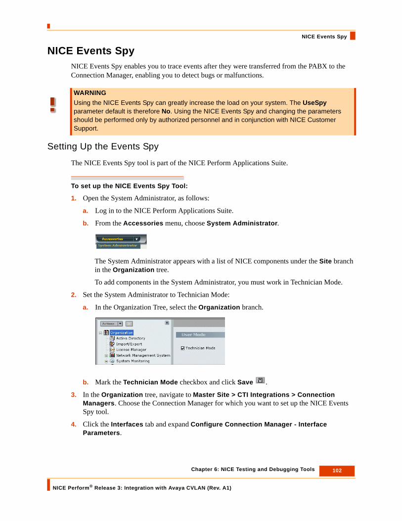
102 Chapter 6: NICE Testing and Debugging Tools
NICE Perform® Release 3: Integration with Avaya CVLAN (Rev. A1)
NICE Events Spy
NICE Events SpyNICE Events Spy enables you to trace events after they were transferred from the PABX to the Connection Manager, enabling you to detect bugs or malfunctions.
Setting Up the Events Spy
The NICE Events Spy tool is part of the NICE Perform Applications Suite.
To set up the NICE Events Spy Tool:
1. Open the System Administrator, as follows:
a. Log in to the NICE Perform Applications Suite.
b. From the Accessories menu, choose System Administrator.
The System Administrator appears with a list of NICE components under the Site branch in the Organization tree.
To add components in the System Administrator, you must work in Technician Mode.
2. Set the System Administrator to Technician Mode:
a. In the Organization Tree, select the Organization branch.
b. Mark the Technician Mode checkbox and click Save .
3. In the Organization tree, navigate to Master Site > CTI Integrations > Connection Managers. Choose the Connection Manager for which you want to set up the NICE Events Spy tool.
4. Click the Interfaces tab and expand Configure Connection Manager - Interface Parameters.
WARNINGUsing the NICE Events Spy can greatly increase the load on your system. The UseSpy parameter default is therefore No. Using the NICE Events Spy and changing the parameters should be performed only by authorized personnel and in conjunction with NICE Customer Support.
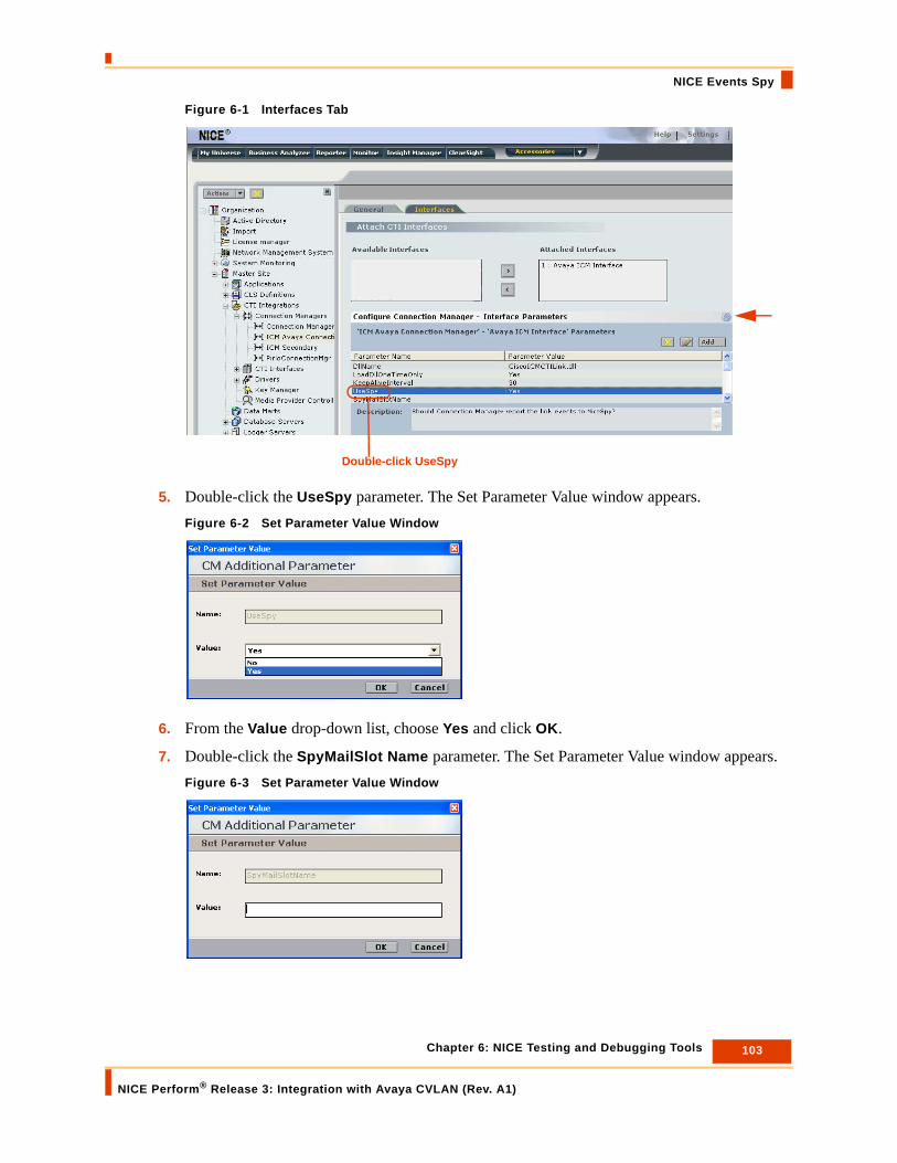
103 Chapter 6: NICE Testing and Debugging Tools
NICE Perform® Release 3: Integration with Avaya CVLAN (Rev. A1)
NICE Events Spy
Figure 6-1 Interfaces Tab
5. Double-click the UseSpy parameter. The Set Parameter Value window appears.Figure 6-2 Set Parameter Value Window
6. From the Value drop-down list, choose Yes and click OK.
7. Double-click the SpyMailSlot Name parameter. The Set Parameter Value window appears.Figure 6-3 Set Parameter Value Window
Double-click UseSpy

104 Chapter 6: NICE Testing and Debugging Tools
NICE Perform® Release 3: Integration with Avaya CVLAN (Rev. A1)
NICE Events Spy
8. In the Value field, type the name of the mailslot that you want to use in conjunction with NICE Events Spy.
9. Click OK.
Receiving Events
You should set up the Events Spy so that you can receive events.
To use NICE Events Spy:
1. On the Interaction Center server, navigate to the Integrations folder (the default location is D:\NICECTI\Integrations). Double-click EventSpy.exe. The Events Spy window appears.Figure 6-4 Events Spy Window
2. From the Connections menu, choose Mailslot Connections for Receiving Events > Open Mailslot. The Events Spy - Mailslot Name window appears.Figure 6-5 Events Spy - Mailslot Name Window
3. Type the name of the mailslot you defined in setting up the NICE Events Spy tool. Click OK.
TIP: It is recommended to use a short name.
NOTE: If the Connection Manager is running, you should restart it after setting these definitions.
Event Type Column

105 Chapter 6: NICE Testing and Debugging Tools
NICE Perform® Release 3: Integration with Avaya CVLAN (Rev. A1)
NICE Events Spy
The Events Spy begins to receive events from the switch. The events are listed in the Event Type column of the Events Spy window, see Figure 6-4.
Saving Events
NICE Events Spy enables you to:
• Create and save events in an active log file.
• Save all current events.
• Save selected current events.
You can save the files in either .xml or .bin formats.
Saving Events in a Log File
This option enables you to create a log file that saves all events from the time you create the file until you close it.
To save events in a log file:
1. From the File menu, choose Log to File.
2. To create a log file using the .xml format, click Log to XML File. To create a log file using the .bin format, click Log to Binary File. The Save as window appears.
3. Save the file in any convenient location.
Saving Current Events
This option enables you to create a file in which you can save all events that currently appear in the Event Type column.
To save current events:
1. From the File menu, choose Save Current Events to File.
2. To create a file using the .bin format, click Save all Events to Binary File. To create a file using the .xml format, click Save all Events to XML File. The Save as window appears.
3. Save the file in any convenient location.
NOTE: To view the contents of any of the log files you created, from the File menu click Open Log File.

106 Chapter 6: NICE Testing and Debugging Tools
NICE Perform® Release 3: Integration with Avaya CVLAN (Rev. A1)
NICE Events Spy
Saving Selected Current Events
This option enables you to create a file in which you can save selected events from the list that currently appears in the Event Type column.
To save selected current events:
1. Select the events you want to save, clicking the events while holding down the <Ctrl> key.
2. From the File menu, choose Log to File.
3. To create a file using the .bin format, click Save Only Selected Events to Binary File. To create a file using the .xml format, click Save Only Selected Events to XML File. The Save as window appears.
4. Save the file in any convenient location.
Setting up the SimCTILink Tool
The SimCTILink tool simulates the transfer of events to the Connection Manager as if they originated in the PABX. This enables you to save and analyze them without having to actually use the PABX itself.
Sending Events
WARNINGUse of the SimCTILink tool must be coordinated in advance with NICE Systems and must be performed only by authorized personnel. DO NOT attempt to use this tool on your own.You must therefore leave the parameter default value as No unless specifically instructed to do so by NICE Customer Support.
WARNINGYou can send events to NICE Systems using the Events Spy window. Sending events is only done when using the SimCTILink tool, and must be coordinated in advance with NICE Customer Support.

107 Chapter 6: NICE Testing and Debugging Tools
NICE Perform® Release 3: Integration with Avaya CVLAN (Rev. A1)
NICE Debug Service
NICE Debug ServiceThe Debug Service enables you to gather data critical for solving problems stemming from the transfer of events between the switch and the Connection Manager.
This section includes the following topics:
• Setting Up the NICE Debug Service
• Accessing the NICE Debug Service
Setting Up the NICE Debug Service
The Debug Service enables developers and customer support personnel to reproduce problematic scenarios.
To set up the Debug Service:
1. Open the System Administrator, as follows:
a. Log in to the NICE Perform Applications Suite.
b. From the Accessories menu, choose System Administrator.
The System Administrator appears with a list of NICE components under the Site branch in the Organization tree.
To add components in the System Administrator, you must work in Technician Mode.
2. Set the System Administrator to Technician Mode:
IMPORTANTDo not attempt to solve bugs or other problems yourself. Use the Debug Service in coordination with NICE Systems to gather the data as described below, and then send it to NICE Customer Support for assistance.
WARNINGUsing the Debug Service can greatly increase the load on your system. The DebugServiceMode parameter default is therefore Idle. Using the Debug Service and changing the parameters should be performed only by authorized personnel and in conjunction with NICE Customer Support.

108 Chapter 6: NICE Testing and Debugging Tools
NICE Perform® Release 3: Integration with Avaya CVLAN (Rev. A1)
NICE Debug Service
a. In the Organization Tree, select the Organization branch.
b. Mark the Technician Mode checkbox and click Save .
3. In the Organization tree, navigate to Master Site > CTI Integrations > Connection Managers. Choose the Connection Manager for which you want to set up the Debug Service.
4. Click the Interfaces tab and expand Configure Connection Manager - Interface Parameters.Figure 6-6 Interfaces Tab
5. Double-click the DebugServiceMode parameter. The Set Parameter Value window appears.Figure 6-7 Set Parameter Value Window
Double-click DebugServiceMode

109 Chapter 6: NICE Testing and Debugging Tools
NICE Perform® Release 3: Integration with Avaya CVLAN (Rev. A1)
NICE Debug Service
6. From the Value drop-down list, choose either Record or Debug (see following table) and click OK.
7. Define the Debug Service parameters according to the following table:
NOTE: You can also create and add additional parameters by clicking Add.
Table 6-1: Debug Service Parameters
Parameter Name Description Default Value
DebugServiceMode • Idle - the Debug Service is disabled.
• Record - the CTI Interface records every event, request, and response.
• Debug - the CTI Interface receives events, requests, and responses directly from the Debug Service (to be used only by NICE System personnel in lab environments).
Idle
DebuggingMode • Orignl_Intrvls - retains the original intervals between events that were used by the switch.
• Fixed_Intrvls - events are transferred to the link at fixed intervals, which are defined in the FixedTimeInterval parameter.
• Single_Step - events are transferred upon user input.
NOTE: This parameter is activated only when you activate the DebugServiceMode.
Single_step
RecordingMode • Asynchronous - synchronization of the requests and responses by the InvokeID is defined by the switch. Not applicable to TAPI.
• Semi_Synchronous - synchronization of the requests and responses by the InvokeID is defined by the Debug Service. Not applicable to TAPI.
• Simple - No synchronization is performed.
NOTE: This parameter is activated only when you activate the DebugServiceMode.
Asynchronous

110 Chapter 6: NICE Testing and Debugging Tools
NICE Perform® Release 3: Integration with Avaya CVLAN (Rev. A1)
NICE Debug Service
8. To activate the Debug Service after you have defined the above parameters, close the Connection Manager process in the Interaction Center server. The Debug Service is activated when the Dispatch Service automatically restarts the Connection Manager process.
DebugFilesFldr Defines the folder in which the files created by the Debug Service are saved.NOTE:
• It is highly recommended to delete the contents of the Debug folder before activating the Debug Service.
• This parameter is activated only when you activate the DebugServiceMode.
• The files are saved in binary format.
Debug
FixedTimeInterval Defines the value when you define Fixed_Intrvls as the value for the DebuggingMode parameter above.NOTE:
• The value is defined in seconds.
• This parameter is activated only when you activate the DebugServiceMode.
0
AvailableDiskQuota Defines the maximum size allowed on the hard disk for the Debug file you defined in the DebugFilesFldr above.
• The value is defined in MB.
• This parameter is activated only when you activate the DebugServiceMode.
300
Table 6-1: Debug Service Parameters (Continued)
Parameter Name Description Default Value

111 Chapter 6: NICE Testing and Debugging Tools
NICE Perform® Release 3: Integration with Avaya CVLAN (Rev. A1)
NICE Debug Service
9. The Debug Service transfers the event data to the file you defined in the DebugFilesFldr above.
For each debug session, the Debug Service automatically creates four debug files:
e_xxxxxxxxxx.dbge_xxxxxxxxxx.ndxr_xxxxxxxxxx.dbgr_xxxxxxxxxx.ndx
in which “xxxxxxxxxx” is the unique debug session identifier. The folder to which the above files are transferred is located in D:\NICECTI\Integrations\Debug (default), or in the location you defined in the DebugFilesFldr parameter above.
IMPORTANTYou must send all four Debug files to NICE Customer Support. If any one of the Debug files is missing, the scenario cannot be reconstructed.
NOTE: To avoid confusion with any Debug files from previous sessions, it is highly recommended to delete all existing Debug file(s) before activating the Debug Service.

112 Chapter 6: NICE Testing and Debugging Tools
NICE Perform® Release 3: Integration with Avaya CVLAN (Rev. A1)
NICE Debug Service
Accessing the NICE Debug Service
NICE Systems provides a utility for viewing the Debug files. You then send the four Debug files to NICE Customer Support.
To access the Debug files:
1. In the Interaction Center, navigate to the Integrations folder (the default location is D:\NICECTI\Integrations).
2. In the Tools folder, double-click IntegrationFileSplitter.exe. The Integration File Splitter window appears.Figure 6-8 Integration File Splitter Window
3. Drag and drop the Debug files into the File Details area. The Debug files and the debug session identifier numbers appear in the File Details area.
4. When necessary, you can open and view the contents of the .dbg files.
Drag and drop debug files into the File Details aras.
IMPORTANTMake sure that you send to NICE Customer Support the four debug files that correspond to the debug session ID number.
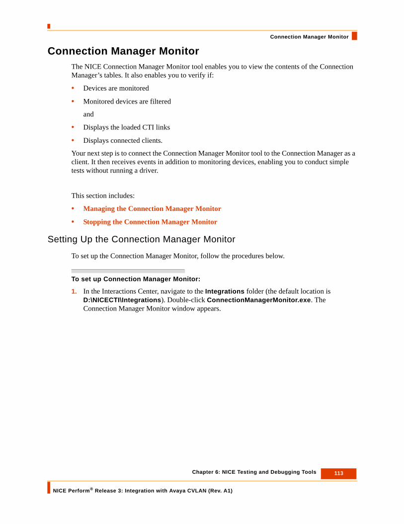
113 Chapter 6: NICE Testing and Debugging Tools
NICE Perform® Release 3: Integration with Avaya CVLAN (Rev. A1)
Connection Manager Monitor
Connection Manager MonitorThe NICE Connection Manager Monitor tool enables you to view the contents of the Connection Manager’s tables. It also enables you to verify if:
• Devices are monitored
• Monitored devices are filtered
and
• Displays the loaded CTI links
• Displays connected clients.
Your next step is to connect the Connection Manager Monitor tool to the Connection Manager as a client. It then receives events in addition to monitoring devices, enabling you to conduct simple tests without running a driver.
This section includes:
• Managing the Connection Manager Monitor
• Stopping the Connection Manager Monitor
Setting Up the Connection Manager Monitor
To set up the Connection Manager Monitor, follow the procedures below.
To set up Connection Manager Monitor:
1. In the Interactions Center, navigate to the Integrations folder (the default location is D:\NICECTI\Integrations). Double-click ConnectionManagerMonitor.exe. The Connection Manager Monitor window appears.

114 Chapter 6: NICE Testing and Debugging Tools
NICE Perform® Release 3: Integration with Avaya CVLAN (Rev. A1)
Connection Manager Monitor
Figure 6-9 Connection Manager Monitor Window
2. From the Monitor menu, choose Connect. The Select Connection Manager window appears.Figure 6-10 Select Connection Manager Window
3. Type the Connection Manager ID of the Interactions Center to which you want to connect. Click OK. The Connection Manager Monitor displays the contents of the Connection Manager tables.
Type the Connection Manager ID of the Interactions Center to which you want to connect

115 Chapter 6: NICE Testing and Debugging Tools
NICE Perform® Release 3: Integration with Avaya CVLAN (Rev. A1)
Connection Manager Monitor
Figure 6-11 Connection Manager Window - Tables
4. From the Client menu of the Connection Manager Monitor window, choose Connect. The Select Connection Manager window appears.Figure 6-12 Connection Manager Window - Client Menu
5. Type the Connection Manager ID of the Interactions Center to which you want to connect. Click OK.
After the Connection Manager Monitor establishes connection to the desired Connection Manager, the Monitor, Stop Monitor, and Disconnect options in the Client menu become enabled. The Client connection appears in the Clients area.
Type the Connection Manager ID of the Interactions Center to which you want to connect
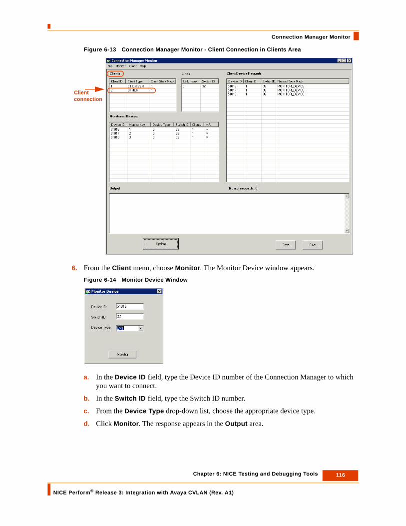
116 Chapter 6: NICE Testing and Debugging Tools
NICE Perform® Release 3: Integration with Avaya CVLAN (Rev. A1)
Connection Manager Monitor
Figure 6-13 Connection Manager Monitor - Client Connection in Clients Area
6. From the Client menu, choose Monitor. The Monitor Device window appears.Figure 6-14 Monitor Device Window
a. In the Device ID field, type the Device ID number of the Connection Manager to which you want to connect.
b. In the Switch ID field, type the Switch ID number.
c. From the Device Type drop-down list, choose the appropriate device type.
d. Click Monitor. The response appears in the Output area.
Client connection

117 Chapter 6: NICE Testing and Debugging Tools
NICE Perform® Release 3: Integration with Avaya CVLAN (Rev. A1)
Connection Manager Monitor
Figure 6-15 Output Area
7. Click Update. The new Client appears in the Client Device Requests area.Figure 6-16 Connection Manager Monitor - Client Device Requests Area
Managing the Connection Manager Monitor
This section includes the following topics:
• Stopping the Connection Manager Monitor
• Disconnecting the Connection Manager Monitor Client
IMPORTANTThe Connection Manager Monitor window does not continuously refresh the data displayed in the window; it only displays the data current at the time you establish the connection. To update the data displayed in the window, click Update.
New Client

118 Chapter 6: NICE Testing and Debugging Tools
NICE Perform® Release 3: Integration with Avaya CVLAN (Rev. A1)
Connection Manager Monitor
Stopping the Connection Manager Monitor
This procedure describes how to stop the Connection Manager Monitor when it is functioning as a client.
To stop the Connection Manager Monitor:
1. From the Client menu of the Connection Manager Monitor window, choose Stop Monitor. The Stop Monitor Device window appears.Figure 6-17 Stop Monitor Device Window
2. Type the Device ID number and the Switch ID of the device you want to stop monitoring.
3. Click Stop Monitor. The response appears in the Output area.
Disconnecting the Connection Manager Monitor Client
This procedure describes how to disconnect the Connection Manager Monitor when it is functioning as a client.
To disconnect the Connection Manager Monitor Client:
• From the Client menu of the Connection Manager Monitor window, choose Disconnect.
The Client connection of the Connection Manager no longer appears in the Clients area and in the Client Device Requests area.

119 Chapter 6: NICE Testing and Debugging Tools
NICE Perform® Release 3: Integration with Avaya CVLAN (Rev. A1)
Log Manager System
Log Manager SystemThe Log Manager system logs all significant system activity and maintains a log of all data, enabling you to view the history of all relevant system activity.
The Log Manager system has four main components:
• Log Manager
• Log Manager Services
• Log Viewer
Log Manager
The Log Manager creates log message files and/or sends information regarding the Console and the Event Log according to the predefined Reporting Level filter.
You can set the reporting levels in any of the integration branches e.g. in the Connection Managers, in the Drivers, in the Key Managers, in the Media Provider Controllers (Observers), or in the New Driver wizards when you initially set up the driver.
By default, reporting levels are defined for the following:
• Console - reports to the standard Console window
• File - reports to the Log file located in the Integrations installation folder
• Event Log - reports to the Log files located in the Event Viewer
If necessary, you can also manage the size of the log files, the amount of disk space dedicated to them, and the number of days you wish to keep log files.
To define the reporting levels:
1. Open the System Administrator, as follows:
a. Log in to the NICE Perform Applications Suite.
b. From the Accessories menu, choose System Administrator.
The System Administrator appears with a list of NICE components under the Site branch in the Organization tree.
WARNINGReporting levels may be helpful for troubleshooting. However, making changes to the reporting levels can greatly add to the load on your system. Changing reporting levels should therefore be done only by authorized personnel and in conjunction with NICE Customer Support.
NOTE: The Event Viewer is a Microsoft feature which can be viewed under the Control Panel > Administrative Tools.

120 Chapter 6: NICE Testing and Debugging Tools
NICE Perform® Release 3: Integration with Avaya CVLAN (Rev. A1)
Log Manager System
To add components in the System Administrator, you must work in Technician Mode.
2. Set the System Administrator to Technician Mode:
• In the Organization Tree, select the Organization branch.
3. Mark the Technician Mode checkbox and click Save .
4. You can set the Reporting Level in any of the branches, see the examples below:
• In the Organization tree, expand Master Site > CTI Integrations > Connection Managers and click the relevant Connection Manager. In the Connection Manager Details area, expand Reporting Level.
-or-
• In the Organization tree, expand Master Site > CTI Integrations > Drivers. In the Driver General Information area, expand Driver Reporting Level.
Figure 6-18 Driver Reporting Level Area
5. Choose the desired row and click Edit . The Set Reporting Level window appears.Figure 6-19 Set Reporting Level Window
Click Edit

121 Chapter 6: NICE Testing and Debugging Tools
NICE Perform® Release 3: Integration with Avaya CVLAN (Rev. A1)
Log Manager System
6. Mark the checkboxes for the reporting levels you want to include and click OK.
7. In the relevant log field, type the new setting and click Save .
Log Manager Services
The Log Manager’s second module can be found in Services. It consists of two log manager related services:
• Nice Integration Log Retention
• Nice Integration Reporting Level Dumper
Log Viewer
The Log Viewer enables you to view the log files and to filter them. You can keep several logs open at the same time.
Filtering Logs
You can filter the logs according to the following criteria:
• Reporting level: Clear the reporting levels that are irrelevant.
• Date: Choose the appropriate time range.
• Module name: Unmark any modules that are irrelevant.
• Thread ID: Unmark any thread IDs that are irrelevant.
• Message: Type any relevant message.
To filter a log file:
1. In the Interaction Center, navigate to the Tools folder (the default location is D:\NICECTI\Integrations\Tools).
2. Double-click LogViewer.exe. The Log Viewer window appears.
NOTE: It is highly recommended that you do not change the settings of the default reporting levels. Changing reporting levels should be done only by authorized personnel and in conjunction with NICE Customer Support.
WARNINGYou should not change any values in the Registry. All changes should be made through the System Administrator application and be done only by authorized personnel and in conjunction with NICE Customer Support.

122 Chapter 6: NICE Testing and Debugging Tools
NICE Perform® Release 3: Integration with Avaya CVLAN (Rev. A1)
Log Manager System
3. Using Windows Explorer, select the relevant log files and drag them to the Log Viewer.
4. In the Filter area, mark the relevant filter options.Figure 6-20 Log Viewer Window
5. Click Filter. The filtered logs appear in the Log Viewer window.
6. To save the filtered log file for future reference: from the File menu, choose Save as. The Save as window appears.
7. Name the filtered log file appropriately.
Searching Logs
The Log Viewer enables you to search for specific text within a specific column or within all columns. The Log Viewer remembers past searches.
To search for a specific text value:
1. From the Edit menu, choose Find. The Find window appears.Figure 6-21 Find Window
2. Click the In column drop-down list and choose the relevant search basis.
3. Click Find next.
Click Filter

123 Chapter 6: NICE Testing and Debugging Tools
NICE Perform® Release 3: Integration with Avaya CVLAN (Rev. A1)
CAPI Spy
CAPI SpyThe CAPI Spy enables you to monitor all messages sent by the CTI driver to the CLS CAPI (Call Server). Examination of these messages enables you to pinpoint whether the problem is in the CTI driver or in the CLS CAPI server.
CAPI Spy has two main components:
• CAPI Spy Plug-in
• CAPI Spy Utility
CAPI Spy Plug-in
The CAPI Spy plug-in is one of the standard CTI driver plug-ins. You set it up in the System Administrator. Only marked plug-ins are executed by the CTI driver.
To set up the CAPI Spy Plug-in:
1. Open the System Administrator, as follows:
a. Log in to the NICE Perform Applications Suite.
b. From the Accessories menu, choose System Administrator.
The System Administrator appears with a list of NICE components under the Site branch in the Organization tree.
To add components in the System Administrator, you must work in Technician Mode.
2. Set the System Administrator to Technician Mode:
a. In the Organization Tree, select the Organization branch.
b. Mark the Technician Mode checkbox and click Save .
3. In the Organization tree, navigate to Master Site > CTI Integrations > Drivers. Click the relevant driver.
4. Click the Interfaces tab.

124 Chapter 6: NICE Testing and Debugging Tools
NICE Perform® Release 3: Integration with Avaya CVLAN (Rev. A1)
CAPI Spy
Figure 6-22 Drivers > Interfaces Tab
5. In the Attach CTI Interfaces section, click the relevant interface driver and click Configure. The Driver - Interface Configuration window appears.Figure 6-23 Driver - Interface Configuration Window
6. Expand Driver Real-Time Plugins.
IMPORTANTYou can mark CAPISpy once and then leave it marked, as it has no negative impact on the system.

125 Chapter 6: NICE Testing and Debugging Tools
NICE Perform® Release 3: Integration with Avaya CVLAN (Rev. A1)
CAPI Spy
Figure 6-24 Driver Real-Time Plugins Area
7. Mark the CAPISpy checkbox and click OK.
8. Click the General tab and expand Additional Driver Parameters. The Additional Driver Parameters area displays.Figure 6-25 Additional Driver Parameters Area
Click the arrows to change the order.
NOTE: It is highly recommended that CAPISpy be the last entry in the Driver Real-Time Plugins list. This enables you to see any changes that may have come about because of other plugins.You can change the order of the drivers by clicking the arrows.After you mark or unmark the CAPISpy checkbox, you must restart the driver before the change will take effect.

126 Chapter 6: NICE Testing and Debugging Tools
NICE Perform® Release 3: Integration with Avaya CVLAN (Rev. A1)
CAPI Spy
9. Define the CAPI Spy parameters according to the following table:
10. Click Save .
CAPI Spy Utility
NICE Systems provides a utility for viewing the CAPI Spy messages in XML format.
To set up the CAPI Spy:
1. In the NICE Interactions Center, navigate to the Integrations folder (the default location is D:\NICECTI\Integrations). Double-click CAPISpy.exe. The CAPI Spy window appears.Figure 6-26 CAPI Spy Window
Table 6-2: CAPI Spy Parameters
Parameter Name Description Default Value
CAPISpyServerPort Port to which the CAPI Spy connects.NOTE: You should not change the value of this parameter unless there is another third party application that uses this port.If the value is changed, restart the driver. Then configure the CAPI Spy application to connect to the new port. See Changing Connection Details.
7002
CAPISpyMessageQueueSize Size of message queue in CAPI Spy server.NOTE: Be careful about setting this to a higher value as it can slow driver performance.
50
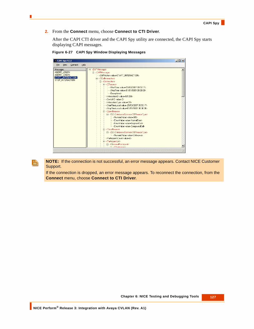
127 Chapter 6: NICE Testing and Debugging Tools
NICE Perform® Release 3: Integration with Avaya CVLAN (Rev. A1)
CAPI Spy
2. From the Connect menu, choose Connect to CTI Driver.
After the CAPI CTI driver and the CAPI Spy utility are connected, the CAPI Spy starts displaying CAPI messages.Figure 6-27 CAPI Spy Window Displaying Messages
NOTE: If the connection is not successful, an error message appears. Contact NICE Customer Support.If the connection is dropped, an error message appears. To reconnect the connection, from the Connect menu, choose Connect to CTI Driver.

128 Chapter 6: NICE Testing and Debugging Tools
NICE Perform® Release 3: Integration with Avaya CVLAN (Rev. A1)
CAPI Spy
Changing Connection Details
The CAPI Spy by default connects to the localhost CTI driver on the 7002 port. When port 7002 is used by another third party application, you can change the port. See CAPI Spy Plug-in.
To change the connection details:
1. From the Connect menu, choose Change connection details. The Connection Details window appears.Figure 6-28 Connection Details Window
2. Type the Driver IP Address and the Driver Spy port.
3. Click OK.
NOTE: You can also monitor CAPI messages from a different host. In this case, type the IP address of the remote machine. This can seriously overload the network and should be avoided if possible.

129 Chapter 6: NICE Testing and Debugging Tools
NICE Perform® Release 3: Integration with Avaya CVLAN (Rev. A1)
CTi Console Viewer
CTi Console Viewer
The CTI Console Viewer enables real-time log tracking of the screens of all integration components installed on the local machine. This application replaces the Console windows in the Reporting Level of the integration process, and provides the user with filtering capability.
CTI Console Viewer has a separate window for each integration process. You can view and filter an event, as well as change the reporting level. You cannot do this in the System Administrator. Files are saved automatically in the Log Manager and can be viewed afterwards in the Log Viewer. Figure 6-29 CTI Console Viewer
To open the CTI Console viewer:
• To open, double-click the icon in the system tray.
-or-
• Right-click the icon, and select Open NICE CTI Console Viewer.
To open a specific integration process window:
1. From the CTI Modules menu, choose the relevant integration process.
A log window opens and the integration modules installed on the local machine are listed. (This list is updated when you add/remove any integration modules in the System Administrator).

130 Chapter 6: NICE Testing and Debugging Tools
NICE Perform® Release 3: Integration with Avaya CVLAN (Rev. A1)
CTi Console Viewer
Figure 6-30 CTI Log Window
Filtering Messages
You can filter messages in any of the following manners:
To reset the filter:
• Click the Reset Filter button.
The filter in Module Name and Thread ID is reset, and all the messages are printed. (The Reset filter option does not affect the reporting level).
NOTE: These reporting levels are only relevant for the CTI Console.
WARNINGReporting levels may be helpful for troubleshooting. However, making changes to the reporting levels can greatly add to the load on your system. Changing reporting levels should therefore be done only by authorized personnel and in conjunction with NICE Customer Support.
• Reporting level - Clear the checkboxes of the reporting levels that are irrelevant (message importance).
• Module name - Clear the checkboxes of any modules that are irrelevant.
• Thread ID - Clear the checkboxes of any Thread IDs that are irrelevant.
NOTE: The filter is applied to new messages. It does not affect old messages.

131 Chapter 6: NICE Testing and Debugging Tools
NICE Perform® Release 3: Integration with Avaya CVLAN (Rev. A1)
CTi Console Viewer
To clear the screen of messages:
• Click the Clear Screen button.
All the messages are cleared from the screen.
To open the last log file:
• Click the Open last log file button.
The current log file with Log Viewer opens (see Log Viewer section). You can see log messages from the specific modules in real-time as they are displayed.
To change console size and color:
1. From the Options menu, choose Console size.
When the log window is filled with the maximum number of messages, the top rows are automatically deleted.
2. From the Options menu, choose Change color.
a. Select a background color.
b. Select a color for each reporting level.

Blank page for double-sided printing.
A
CVLAN Additional Parameters
CTI Interface - Additional Switch Parameters............................................................134
Importing Text Files......................................................................................................136
Reporting Levels ..........................................................................................................138
Logger Parameters for Instant Callback.....................................................................140
Connection Manager - Additional Parameters...........................................................141
Connection Manager - Interface Parameters .............................................................143
Switch Driver - Additional Parameters .......................................................................145
Driver Interface - Additional Parameters ....................................................................147
Appendix A: CVLAN Additional Parameters
NICE Perform® Release 3: Integration with Avaya CVLAN (Rev. A1)
133

CTI Interface - Additional Switch Parameters
CTI Interface - Additional Switch Parameters
Additional Parameters for configuring the CTI Interface are located in the Switch Connection and Additional Information window of the CTI Interface wizard (see Configuring the CTI Interface on page 54).Figure A-1 Switch Connection and Additional Information Window
WARNINGChanging parameters could have severe effects on your system. Therefore changing the CTI Interface Additional Parameters, or creating new ones, should be done only by authorized personnel.
134 Appendix A: CVLAN Additional Parameters
NICE Perform® Release 3: Integration with Avaya CVLAN (Rev. A1)

CTI Interface - Additional Switch Parameters
The following predefined additional parameters appear for the Avaya Communication Manager and Media Server switch:
To change the default values:
1. Double-click the row of the relevant parameter.
The Driver Additional Parameter window appears.
2. Enter the desired value in the Value field.
3. Click OK.
NOTE: You can also create and add additional parameters by clicking the Add button.
Parameter Name Description Default Value
HeartBeatTimeOut Indicates the time (in seconds) that is allowed for the CVLAN server to determine when the client is no longer sending requests or messages and to drop the connection.
30
LinkFIFOSize Indicates the size of the FIFOs in the link. 500
TreatUCID Indicates how to treat the Universal Call ID (UCID).Either as a (yes) string value or a (no) value in Hex format.
Yes
TotalNumOfSwitchDevices Indicates the number of devices supported by the link.
5000
TrunkIdentifier Defines the trunk identifier (that is, the prefix used to identify a trunk number).
#.*
MaxLenOfInternalDevice Defines the maximum length (that is, the maximum number of digits) in an internal device.
6
DefaultDeviceType Indicates the device type to use in case of an unknown device type.
Station
135 Appendix A: CVLAN Additional Parameters
NICE Perform® Release 3: Integration with Avaya CVLAN (Rev. A1)

Importing Text Files
Importing Text FilesWhen you configure your CTI Interface(s) as described in Chapter Configuring the CTI Interface on page 54, (see especially the NOTE on page 61), you can save time by importing the device number and the corresponding device type from existing .txt files.
In order to use the Import feature, the .txt file must be formatted as follows:
• Each line in the .txt file must represent one device.
• Each line must include both the device number and its corresponding device type.
• The device number and its corresponding device type must be separated by either a single space or by one tab increment.
To import text files:
1. In the Switch Devices Configuration window, expand the Available Devices row. Figure A-2 Switch Devices Configuration Window
2. Click the Import button.
The Import window appears.
NOTE: The file(s) must be in .txt format. If you have existing files in any other format, you must first convert them to .txt format and then perform the procedures described below.
136 Appendix A: CVLAN Additional Parameters
NICE Perform® Release 3: Integration with Avaya CVLAN (Rev. A1)

Importing Text Files
Figure A-3 Import Window
3. If you want to overwrite all the devices that currently appear in the Available Devices window, mark the Clear all existing values checkbox.
4. In the Delimiter drop-down list, choose if the delimiter that separates the device number from its corresponding type is a Space or a Tab increment.
5. In the Records separator drop-down list, accept the default New Line.
6. In the Fields order drop-down list, choose if the order in which the device number and its corresponding type that appears in the txt file is Device Delimiter Device Type (that is, first the device number followed by the device type), or Device Type Delimiter Device (that is, first the device type followed by the device number).
7. In the Import File field, browse to the file you want to import.
8. Click OK.
The devices listed in the .txt file are configured into the CTI Interface.
WARNINGBy default, the Clear all existing values checkbox is marked. If you want to retain the devices that are currently listed in the Available Devices window, you must unmark the checkbox.
137 Appendix A: CVLAN Additional Parameters
NICE Perform® Release 3: Integration with Avaya CVLAN (Rev. A1)

Reporting Levels
Reporting Levels
Reporting Levels are defined in the General Information window of the Connection Manager and the New Driver wizards (see Configuring the Connection Manager on page 66 and Creating the Switch Driver on page 70).Figure A-4 General Information Window
WARNINGReporting Levels may be helpful for troubleshooting. However, making changes to the Reporting Levels can greatly add to the load on your system. Changing Reporting Levels should therefore be done only by authorized personnel and in conjunction with NICE Systems.
138 Appendix A: CVLAN Additional Parameters
NICE Perform® Release 3: Integration with Avaya CVLAN (Rev. A1)

Reporting Levels
By default, reporting levels are defined for the following:
• Console - reports to the NICE Log Manager
• File - reports to the Log file located in the Integrations installation folder
• Event Log - reports to the Log files located in the Event Viewer
To define reporting levels:
1. Choose the desired row and click the Edit button.
The Set Reporting Level window appears.Figure A-5 Set Reporting Level Window
2. Mark the checkboxes for the reporting levels you want to include and click OK.
NOTE: The Event Viewer is a Microsoft feature which can be viewed under the Control Panel > Administrative Tools.
139 Appendix A: CVLAN Additional Parameters
NICE Perform® Release 3: Integration with Avaya CVLAN (Rev. A1)
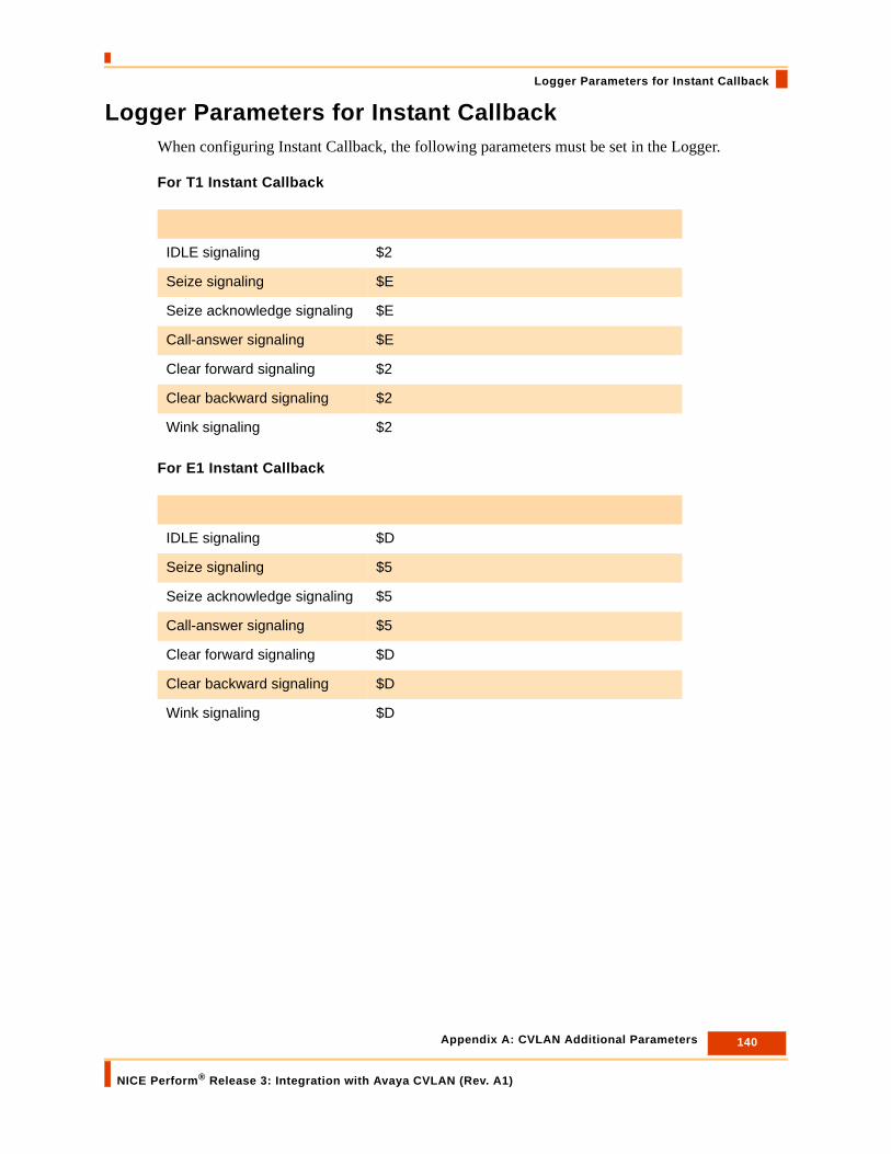
Logger Parameters for Instant Callback
Logger Parameters for Instant CallbackWhen configuring Instant Callback, the following parameters must be set in the Logger.
For T1 Instant Callback
For E1 Instant Callback
IDLE signaling $2
Seize signaling $E
Seize acknowledge signaling $E
Call-answer signaling $E
Clear forward signaling $2
Clear backward signaling $2
Wink signaling $2
IDLE signaling $D
Seize signaling $5
Seize acknowledge signaling $5
Call-answer signaling $5
Clear forward signaling $D
Clear backward signaling $D
Wink signaling $D
140 Appendix A: CVLAN Additional Parameters
NICE Perform® Release 3: Integration with Avaya CVLAN (Rev. A1)

Connection Manager - Additional Parameters
Connection Manager - Additional Parameters
Additional Parameters for configuring the Connection Manager are located in the General Information window of the Connection Manager wizard (see Configuring the Connection Manager on page 66).Figure A-6 General Information Window
WARNINGChanging parameters may have severe effects on your system. Therefore changing the Connection Manager Additional Parameters, or creating new ones, should be done only by authorized personnel.
141 Appendix A: CVLAN Additional Parameters
NICE Perform® Release 3: Integration with Avaya CVLAN (Rev. A1)

Connection Manager - Additional Parameters
The following predefined additional parameters appear:
To change the default value:
1. Double-click the row of the relevant parameter.
The CM Additional Parameter window appears.
2. Enter the desired value in the Value field and click OK.
NOTE: You can also create and add additional parameters by clicking the Add button.
Parameter Name Description Default Value
MaxClientDeviceRequests Defines the maximum number of device requests the Connection Manager can handle.
1000
MaxClientRequests Defines the maximum number of client requests the Connection Manager can handle.
1000
MaxClients Defines the maximum number of clients that can be attached to the Connection Manager.
100
MaxMonitoredDevices Defines the maximum number of monitored devices which the Connection Manager can handle. For example, if the value is 1000 the Connection Manager can handle 999 monitored devices.
1000
MaxSwitchIdToCTILinkEntries Defines the maximum number of CTI links the Connection Manager can handle.
10
142 Appendix A: CVLAN Additional Parameters
NICE Perform® Release 3: Integration with Avaya CVLAN (Rev. A1)

Connection Manager - Interface Parameters
Connection Manager - Interface Parameters
Interface Parameters for the Connection Manager are located in the Connection Manager Switches Information window of the Connection Manager wizard (see Configuring the Connection Manager on page 66).Figure A-7 Connection Manager Switches Window
WARNINGChanging parameters may have severe effects on your system. Therefore changing the Connection Manager Interface Parameters, or creating new ones, should be done only by authorized personnel.
143 Appendix A: CVLAN Additional Parameters
NICE Perform® Release 3: Integration with Avaya CVLAN (Rev. A1)
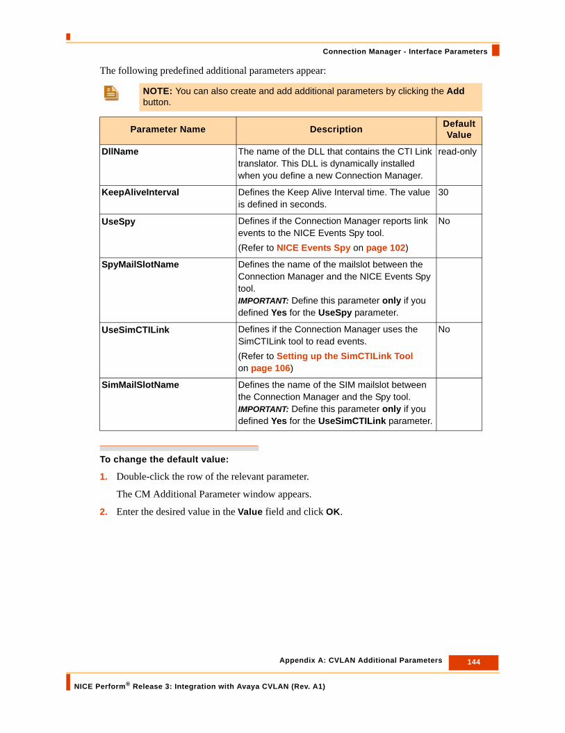
Connection Manager - Interface Parameters
The following predefined additional parameters appear:
To change the default value:
1. Double-click the row of the relevant parameter.
The CM Additional Parameter window appears.
2. Enter the desired value in the Value field and click OK.
NOTE: You can also create and add additional parameters by clicking the Add button.
Parameter Name Description Default Value
DllName The name of the DLL that contains the CTI Link translator. This DLL is dynamically installed when you define a new Connection Manager.
read-only
KeepAliveInterval Defines the Keep Alive Interval time. The value is defined in seconds.
30
UseSpy Defines if the Connection Manager reports link events to the NICE Events Spy tool.(Refer to NICE Events Spy on page 102)
No
SpyMailSlotName Defines the name of the mailslot between the Connection Manager and the NICE Events Spy tool. IMPORTANT: Define this parameter only if you defined Yes for the UseSpy parameter.
UseSimCTILink Defines if the Connection Manager uses the SimCTILink tool to read events.(Refer to Setting up the SimCTILink Tool on page 106)
No
SimMailSlotName Defines the name of the SIM mailslot between the Connection Manager and the Spy tool. IMPORTANT: Define this parameter only if you defined Yes for the UseSimCTILink parameter.
144 Appendix A: CVLAN Additional Parameters
NICE Perform® Release 3: Integration with Avaya CVLAN (Rev. A1)

Switch Driver - Additional Parameters
Switch Driver - Additional Parameters
Additional Parameters for configuring the Switch Driver are located in the General Information window of the Switch Driver wizard (see Creating the Switch Driver on page 70).Figure A-8 General Information Window
WARNINGChanging parameters may have severe effects on your system. Therefore changing the Switch Driver Additional Parameters, or creating new ones, should be done only by authorized personnel.
145 Appendix A: CVLAN Additional Parameters
NICE Perform® Release 3: Integration with Avaya CVLAN (Rev. A1)
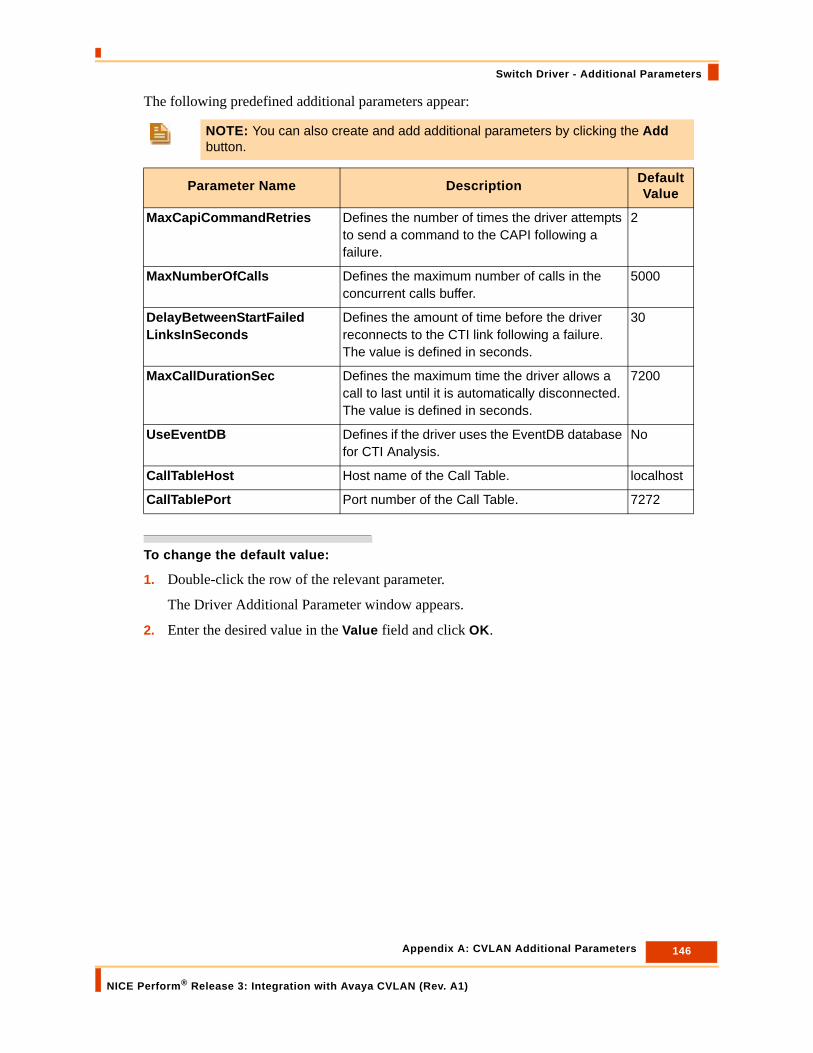
Switch Driver - Additional Parameters
The following predefined additional parameters appear:
To change the default value:
1. Double-click the row of the relevant parameter.
The Driver Additional Parameter window appears.
2. Enter the desired value in the Value field and click OK.
NOTE: You can also create and add additional parameters by clicking the Add button.
Parameter Name Description Default Value
MaxCapiCommandRetries Defines the number of times the driver attempts to send a command to the CAPI following a failure.
2
MaxNumberOfCalls Defines the maximum number of calls in the concurrent calls buffer.
5000
DelayBetweenStartFailedLinksInSeconds
Defines the amount of time before the driver reconnects to the CTI link following a failure. The value is defined in seconds.
30
MaxCallDurationSec Defines the maximum time the driver allows a call to last until it is automatically disconnected. The value is defined in seconds.
7200
UseEventDB Defines if the driver uses the EventDB database for CTI Analysis.
No
CallTableHost Host name of the Call Table. localhost
CallTablePort Port number of the Call Table. 7272
146 Appendix A: CVLAN Additional Parameters
NICE Perform® Release 3: Integration with Avaya CVLAN (Rev. A1)

Driver Interface - Additional Parameters
Driver Interface - Additional Parameters
Additional Parameters for configuring the Driver Interface are located in the Driver Interface Configuration window of the Switch Driver wizard (see Creating the Switch Driver on page 70).Figure A-9 General Information Window
WARNINGChanging parameters may have severe effects on your system. Therefore changing the Driver Interface Additional Parameters, or creating new ones, should be done only by authorized personnel.
147 Appendix A: CVLAN Additional Parameters
NICE Perform® Release 3: Integration with Avaya CVLAN (Rev. A1)

Driver Interface - Additional Parameters
The following predefined additional parameters appear:
To change the default value:
1. Double-click the row of the relevant parameter.
The Driver Additional Parameter window appears.
2. Enter the desired value in the Value field and click OK.
NOTE: You can also create and add additional parameters by clicking the Add button.
Parameter Name Description Default Value
op_EnableFlushCalls Defines if the driver flushes open calls when initializing connection.
Yes
SaveOriginalMapDevice Defines if the driver reports to the source device.
No
HandleAgentActivityOnly Defines if the driver handles login/logout events only from this link.
No
TimeOut Defines the response time for a request. The value is defined in milliseconds.
3000
MilliDelayBetweenCTIRequests
Defines the waiting time between CTI requests. The value is defined in milliseconds.
100
CTIRequestsRetries Defines the number of times the CTI tries to request events for Query and Monitor devices.
2
MilliDelayBetweenGetLinkStatusRequests
Defines the waiting time between “Get Link Status” requests. The value is defined in milliseconds.
5000
GetLinkStatusRetries Defines the number of times “Get Link Status” requests can be made.
4
FailedMonitoredThreadMinutesDelay
Defines the waiting time before reactivating a thread to monitor devices that the link had previously failed to monitor. The value is defined in minutes.
10
148 Appendix A: CVLAN Additional Parameters
NICE Perform® Release 3: Integration with Avaya CVLAN (Rev. A1)

Index
Aactive VoIPAvaya components 20NICE components 21
additional parametersConnection Manager 141, 143CTI Interface 134driver interface 147switch driver 145
AESswitch communication 98troubleshooting 98version 98
Application Enablement Services (AES) 16Avaya AES Server
configuration information 52configuring the Connection Manager 66configuring the CTI Interface 54configuring the Switch Driver 70installing the Switch Driver 81switch configuration 44switch preparations 44
Avaya Communication ManagerMedia Gateway 15Media Server 15
Avaya componentsactive VoIP 20passive VoIP 22
Avaya CT Serverconfiguration information 52configuring the Connection Manager 66configuring the CTI Interface 54configuring the Switch Driver 70installing the Switch Driver 81
Avaya environmentpreparing AES for CVLAN 43
Bbusiness data
database fields 25
CCLAN 16
Connection Manageradditional parameters 141, 143attaching CTI Interfaces 68configuration prerequisites 53configuration wizard 66
CTI Interfaceadding devices 61, 77additional parameters 134configuration prerequisites 52configuration wizard 54creating new physical switch 57
CTI linkconfiguring via OAM 47defining 47
CTI/CDR Interfaceimporting text files 136
customer componentspassive VoIP 23
CVLAN 15CVLAN environment 15defining the CTI link 47
CVLAN client 15installation 50
CVLAN server 16
Ddevice deletion 95devices, failed to monitor
troubleshooting 94driver interface
additional parameters 147driver, see integration driverDS1 cards
configuration 31configuring basic parameters 32connecting 31
EEvents Spy
defining SpyMailSlot Name parameter 103defining the UseSpy parameter 103sending events 106
extension-side recording
Index
NICE Perform® Release 3: Integration with Avaya CVLAN (Rev. A1)
149

architecture 18
IInstant Callback
configuration 31integration
architecture 15description 14limitations 26recording solutions 17
integration driveropen stream failure 95
integration workflowCVLAN integration 13
interaction-based recording 17IP/Name field 83
Llimitations 26Logger 16login/logout error
troubleshooting 93
MMDF
connections 30monitor end event 95monitoring devices
troubleshooting 94
NNICE components
active VoIP 21passive VoIP 23
NICE Events Spy 102setting up the SimCTILink Tool 106
NICE Interaction CenterCVLAN client installation 50
NICE Interaction Center (CLS) 16NICE Perform
switch integration prerequisites 12
OOAM
CTI link configuration 47switch configuration 44
open stream failuretroubleshooting 95
Ppassive VoIP
Avaya components 22
customer components 23NICE components 23
peparing AES for CVLAN 44preparing AES environment 44
Rrecording
solutions 17recording methods 17reporting levels
defining 138
SS1 cards
configuring E1 trunks 35configuring T1 trunks 37
SimCTILink tool 106SpyMailSlot Name parameter 103switch
configuration for AES 44configuring DS1 cards 31open stream failure 95
switch driveradding devices 79adding rejected devices 78additional parameters 145attaching CLS 72configuration prerequisites 53configuration wizard 70defining monitor devices 76installation 81IP/Name field 83
switch integrationprerequisites 12
system architectureExtension-Side recording 18Trunk-Side recording 19
Ttext files
importing 136total recording 17trunk-side recording
architecture 19
UUseSpy parameter 103
VVDN, missing information
troubleshooting 94
Index
NICE Perform® Release 3: Integration with Avaya CVLAN (Rev. A1)
150