Embed Size (px)
Citation preview

AVATAR Deliverable D1.2 Reference Blade Design
January 30, 2015 Agreement n.: FP7-ENERGY-2013-1/ n° 608396 Duration: November 2013 to November 2017 Coordinator: ECN Wind Energy, Petten, The Netherlands
Supported by:

Page 2 of 52 WP1.2: Design for the AVATAR RWT Rotor
Document information
Document Name: AVATAR Reference Blade Design
Confidentiality Class XX
Document Number: D1.2
Editor: G. Sieros (CRES)
Contributing authors: D. Lekou, D. Chortis, P. Chaviaropoulos (CRES)
X. Munduate, A. Irisarri (CENER)
H. Aa. Madsen, K. Yde, K. Thomsen(DTU)
M. Stettner, M. Reijerkerk (GE)
F. Grasso, R. Savenije, G. Schepers (ECN)
C.F. Andersen (LM)
Review: G. Schepers (ECN)
Date: 30/01/2015
WP: WP1 - Integration and Evaluation of 10MW Rotor
Task: Task1.2 Design for the AVATAR RWT Rotor

Page 3 of 52 WP1.2: Design for the AVATAR RWT Rotor
Table of contents
1 Introduction 4
2 Specifications 5
3 Airfoil Selection 7
4 Planform Design 11
5 Structural Design 16
5.1 Initial Design 16 5.1.1 Geometry 16 5.1.2 Loads 16 5.1.3 Static Analysis 18 5.1.4 Modal Analysis 23 5.1.5 Buckling Analysis 23 5.1.6 Mass & Stiffness Distribution 24 5.2 Redesign of the blade 25 5.2.1 Initial Design for weight estimation 27
6 Loads and Stability 40
6.1 Test Cases 40 6.2 Computational Tools 40 6.3 Results 42 6.3.1 Power Curve Verification 42 6.3.2 Speed-up/Speed-down simulations 45 6.3.3 Unsteady operation 47
7 Conclusions 51
8 References 52

Page 4 of 52 WP1.2: Design for the AVATAR RWT Rotor
1 Introduction This document represents Deliverable D1.2 of the AVATAR project, containing the design
process followed for the reference wind turbine. The design is based on the INNWIND.EU
10MW research wind turbine, with modifications in order to explore more demanding flow
regimes. A detailed description of the resulting geometry and structural properties is also part of
the deliverable. Throughout this document, the “baseline 10MW wind turbine” referred to is the
INNWIND.EU research wind turbine / DTU 10MW RWT (Bak, et al.)

Page 5 of 52 WP1.2: Design for the AVATAR RWT Rotor
2 Specifications Even though it was not possible (or required) to have a production-quality design for the project,
a connection to standard industry practices was maintained. The industrial partners provided the
general guidelines for the blade design that would need to be satisfied. These included
manufacturability constraints and a minimum set of IEC load cases to be checked at the initial
design stage. Details of the constrains that were used are given in (Stettner & Chaviaropoulos,
2014)
It is useful to introduce the background for the design that is proposed. We use the standard
definitions for Tip-Speed-Ratio (TSR or λ), blade section lift to drag ratio k and the radius
fraction x according to Eq. (1). We denote V the ambient wind speed, ω the rotational speed
and R the rotor radius and B is the number of blades.
𝜆 = 𝜔𝑅/𝑉 𝑘 = 𝐶𝐿/𝐶𝐷 𝑥 = 𝑟/𝑅 (1)
We introduce the non-dimensional lift distribution Λ(λ,x) as
𝛬(𝜆, 𝑥) =𝑐(𝜆, 𝑥)𝐶𝐿
𝑅 (2)
where c(λ,x) is the chord distribution and CL the lift coefficient.
For a pitch-controlled, variable speed HAWT design and for a given rotor radius the classical
rotor aerodynamic design problem would seek to maximize the energy capture by maximizing
the power coefficient CP. According to the BEM theory this would happen for an axial induction
value α=1/3 and would correspond to a TSR design value λ which gets larger (along with CP,MAX)
as the aerodynamic performance of the blades k gets better (higher). As design λ increases the
non-dimensional lift distribution Λ(λ,x) gets smaller and, for the same family of blade profiles, the
rotor solidity gets lower.
For a variable speed rotor, the design λ value (and therefore CP,MAX) can be maintained over a
range starting from a minimum wind speed, defined by the low-end capability of the variable-
speed power conversion system, up to a maximum wind speed which is limited by the rotor
maximum tip-speed, either for restraining noise or centrifugal loading. We shall call this
maximum wind speed, where CP = CP,MAX , “design wind speed”. Usually, the pitch variable
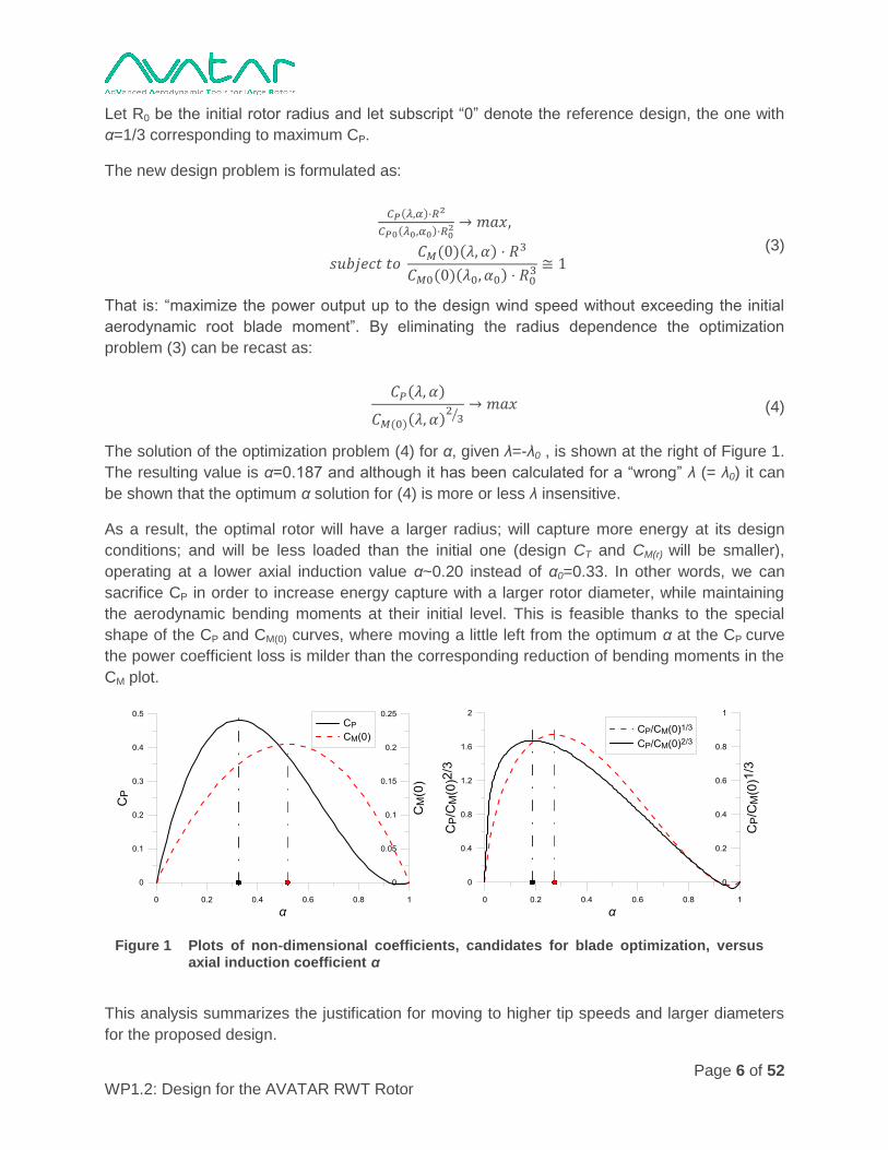
speed turbines have their design wind speed just below their rated speed. The left of Figure 1
presents a plot of CP versus α for a three-bladed rotor with profiles of k=100. The CP,MAX value is
0.4966 corresponding to an α value of 1/3.
Suppose that we have an initial (reference) wind turbine and we want to add some freedom in
our design by redesigning the rotor, letting its radius free, but respecting all turbine related
constrains (the rated rotational speed and power, the hub loading etc). We will assume for
simplicity that the new rotor will use the same family of airfoils (same k, considering Reynolds
number effects as secondary at the scale of our interest).
Page 6 of 52 WP1.2: Design for the AVATAR RWT Rotor
Let R0 be the initial rotor radius and let subscript “0” denote the reference design, the one with
α=1/3 corresponding to maximum CP.
The new design problem is formulated as:
𝐶𝑃(𝜆,𝛼)⋅𝑅2
𝐶𝑃0(𝜆0,𝛼0)⋅𝑅02 → 𝑚𝑎𝑥,
𝑠𝑢𝑏𝑗𝑒𝑐𝑡 𝑡𝑜 𝐶𝑀(0)(𝜆, 𝛼) ⋅ 𝑅3
𝐶𝑀0(0)(𝜆0, 𝛼0) ⋅ 𝑅03 ≅ 1
(3)
That is: “maximize the power output up to the design wind speed without exceeding the initial
aerodynamic root blade moment”. By eliminating the radius dependence the optimization
problem (3) can be recast as:
𝐶𝑃(𝜆, 𝛼)
𝐶𝑀(0)(𝜆, 𝛼)2
3⁄→ 𝑚𝑎𝑥 (4)
The solution of the optimization problem (4) for α, given λ=-λ0 , is shown at the right of Figure 1.
The resulting value is α=0.187 and although it has been calculated for a “wrong” λ (= λ0) it can
be shown that the optimum α solution for (4) is more or less λ insensitive.
As a result, the optimal rotor will have a larger radius; will capture more energy at its design
conditions; and will be less loaded than the initial one (design CT and CM(r) will be smaller),
operating at a lower axial induction value α~0.20 instead of α0=0.33. In other words, we can
sacrifice CP in order to increase energy capture with a larger rotor diameter, while maintaining
the aerodynamic bending moments at their initial level. This is feasible thanks to the special
shape of the CP and CM(0) curves, where moving a little left from the optimum α at the CP curve
the power coefficient loss is milder than the corresponding reduction of bending moments in the
CM plot.
This analysis summarizes the justification for moving to higher tip speeds and larger diameters
for the proposed design.
Figure 1 Plots of non-dimensional coefficients, candidates for blade optimization, versus axial induction coefficient α

Page 7 of 52 WP1.2: Design for the AVATAR RWT Rotor
3 Airfoil Selection The geometrical characteristics of the airfoils were not fixed at the specifications level, as they
were going to be part of the design procedure. It is expected that because of the unusual
aerodynamic characteristics of the wind turbine, existing airfoil families are probably suboptimal
for the final design. A new set of airfoil families will be produced later in the course of the
project, but for the reference wind turbine, an existing family needs to be utilized. The main
requirements were that it is readily available, and that some experimental data for operation at
various Reynolds numbers are also available (though further tests at high Re numbers will be
performed in the context of the project).
It was therefore decided to use the established
DU airfoil families at thicknesses shown in
Error! Not a valid bookmark self-reference..
The main challenge lies in acquiring reliable
polar curves for theses airfoils at the very high
Re numbers involved. As the planform design
was not finalized at the time of the airfoil
selection, an estimate was performed
assuming chords similar to the ones used for
the INNWIND.EU rotor. The proposed sections
are based on the following assumptions
1. We assume that (as a first approximation)
the INNWIND.EU rotor is scaled in the
radial direction, but not in the other
directions, so that the chord lengths remain
similar (this is compatible with the
requirement to retain bending moments similar to the INNWIND rotor)
2. A scaling factor of 1.15 is applied in the radial direction
3. The rotating speed is the same as for the INNWIND.EU rotor (9.6RPM at rated, 6RPM
minimum)
4. A similar hub → tip thickness distribution is used
5. The twist distribution is not known at this moment, but is not important for the polars
calculation
Based on these simplifying assumptions, a preliminary distribution of the sections would be as
shown in the following table. This is not necessarily an accurate description of the final
geometry, but as we are only interested in defining the approximate Reynolds number, it should
be sufficient.
Table 1 Airfoil sections used for the reference blade
60.0% Artificial based on thickest available DU
40.1% DU 00-W2-401
35.0% DU 00-W2-350
30.0% DU 97-W-300
24.0% DU 91-W2-250 (modified for t/c=24%)
21.0% Based on DU 00-W-212 – added trailing edge thickness

Page 8 of 52 WP1.2: Design for the AVATAR RWT Rotor
Table 2 Estimate of airfoil operating conditions
Radius [%] 17 25 32 40 55 95 Chord [m] 5.7 6.1 6.2 5.8 5 1.8 t/c [%] 60 40 35 30 21-24 21-24
The resulting design conditions are summarized in Table 3. The 24% and 21% airfoils will be
used for a larger part of the blade, so conditions characteristic for 50%, 75% and 95% of the
radius are included.
Initial polars were estimated using the RFOIL computational method developed at ECN. Full
360deg polars were produced for all the design conditions, so that they can be used for
aeroelastic as well as performance calculations.
Table 3 Design conditions for the airfoils used for the AVATAR RWT
Section Thickness
Re (rated) Ma (rated) Re (Min) Ma (Min)
60.0% 7.0×10⁶ 0.05 4.4×10⁶ 0.03
40.1% 11.0×10⁶ 0.07 7.0×10⁶ 0.05
35.0% 14.0×10⁶ 0.09 9.0×10⁶ 0.06
30.0% 17.0×10⁶ 0.12 10.0×10⁶ 0.07
24.0% 20.0×10⁶ 0.16 12.0×10⁶ 0.10
24.0% 16.0×10⁶ 0.25 11.0×10⁶ 0.15
24.0% 13.0×10⁶ 0.30 8.0×10⁶ 0.18
21.0% 20.0×10⁶ 0.16 12.0×10⁶ 0.10
21.0% 16.0×10⁶ 0.25 11.0×10⁶ 0.15
21.0% 13.0×10⁶ 0.30 8.0×10⁶ 0.18
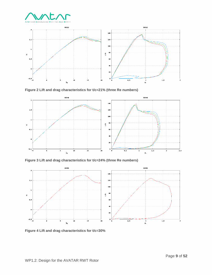
The results for the different airfoil families are given in Figure 2 - Figure 7. The performance
levels have been adjusted to be consistent with expected values at lower Reynolds numbers (to
compensate for a tendency to overpredict the performance). A trailing edge thickness from 0.6-
1.5% is used, in-line with the values used in INNWIND.EU and the specifications for
manufacturability.
Page 9 of 52 WP1.2: Design for the AVATAR RWT Rotor
Figure 2 Lift and drag characteristics for t/c=21% (three Re numbers)
Figure 3 Lift and drag characteristics for t/c=24% (three Re numbers)
Figure 4 Lift and drag characteristics for t/c=30%

Page 10 of 52 WP1.2: Design for the AVATAR RWT Rotor
Figure 5 Lift and drag characteristics for t/c=35%
Figure 6 Lift and drag characteristics for t/c=40%
Figure 7 Lift and drag characteristics for t/c=60%
Page 11 of 52 WP1.2: Design for the AVATAR RWT Rotor
4 Planform Design For the given airfoil families, an optimized spanwise distribution of the chord, thickness and twist
Figure 9) were obtained through an iterative process. The reference blade from the
INNWIND.EU project (Table 4) was used as a starting point, with modifications respecting the
general specifications agreed upon for the AVATAR blade (Stettner & Chaviaropoulos, 2014).
The constraints on the resulting blade were:
The specific power should be drastically
reduced (from 400W/m2 → 300W/m2). This goes
together with an increase of blade radius from
89 to 102.5 meter.
Thrust decreased, so that bending moment at
tower bottom remains constant
Rotational speed should be kept the same (i.e.
a rated value of 9.6 rpm), so that the other
subcomponents will be interchangeable
between the two wind turbines.
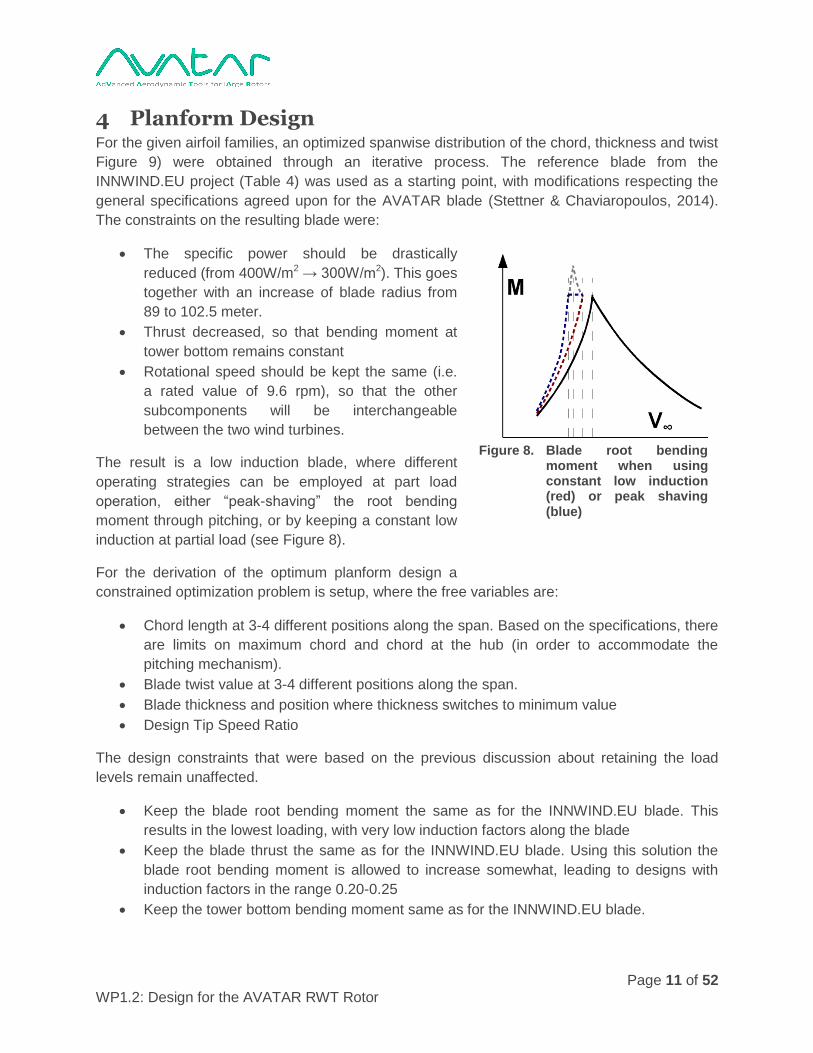
The result is a low induction blade, where different
operating strategies can be employed at part load
operation, either “peak-shaving” the root bending
moment through pitching, or by keeping a constant low
induction at partial load (see Figure 8).
For the derivation of the optimum planform design a
constrained optimization problem is setup, where the free variables are:
Chord length at 3-4 different positions along the span. Based on the specifications, there
are limits on maximum chord and chord at the hub (in order to accommodate the
pitching mechanism).
Blade twist value at 3-4 different positions along the span.
Blade thickness and position where thickness switches to minimum value
Design Tip Speed Ratio
The design constraints that were based on the previous discussion about retaining the load
levels remain unaffected.
Keep the blade root bending moment the same as for the INNWIND.EU blade. This
results in the lowest loading, with very low induction factors along the blade
Keep the blade thrust the same as for the INNWIND.EU blade. Using this solution the
blade root bending moment is allowed to increase somewhat, leading to designs with
induction factors in the range 0.20-0.25
Keep the tower bottom bending moment same as for the INNWIND.EU blade.
Figure 8. Blade root bending
moment when using constant low induction (red) or peak shaving (blue)

Page 12 of 52 WP1.2: Design for the AVATAR RWT Rotor
Table 4 INNWIND.EU wind turbine general characteristics (Bak, et al.)
Wind Regime IEC Class 1A
Rotor Orientation Clockwise rotation - Upwind
Control Variable Speed
Collective Pitch
Cut in wind speed 4
Cut out wind speed 25
Rated wind speed 11.4
Rated power 10
Number of blades 3
Rotor Diameter 178.3
Hub Diameter 5.6
Hub Height 119.0
Minimum Rotor Speed 6.0
Maximum Rotor Speed 9.6
Maximum Generator Speed 480.0
Gearbox Ratio 50.0
Maximum Tip Speed 90.0
Different optimization strategies were tried at ECN and CRES. In the simplest case the pitch
angle was constant up to rated speed and only allowed to vary from there on, in order to keep
the power output constant. In some of the examined cases, the pitching schedule was allowed
to vary in the benefit of power capture but, also, with increased mean flapping loads
Figure 9 Planform design for the reference wind turbine

Page 13 of 52 WP1.2: Design for the AVATAR RWT Rotor
A comparison between the initial INNWIND.EU blade, the proposed AVATAR blade and the
SANDIA 100m blade (Griffith & Ashwill, The Sandia 100-meter all-glass baseline wind turbine
blade: SNL100-00, 2011) (Griffith, The SNL-100-01 Blade: Carbod Design Studies for the
Sandia 100m Blade, 2013), which is designed for a 13MW generator. As seen in Figure 12 the
chord distribution is similar between the two designs, while a substantially larger chord is used
for the Sandia blade. The actual (absolute) thicknesses of the blades are quite close to each
other.
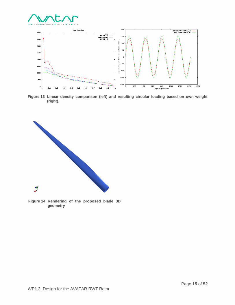
The linear density of the Sandia blade is also larger, resulting in a substantially heavier blade
(expected because of the 30% larger power). Nevertheless, and in spite of the constraint for
constant blade loading, the AVATAR blade unavoidably has a higher fatigue loading, compared
to the INNWIND.EU blade (Figure 13).
Figure 10 Spanwise distribution of properties for different wind speeds. The results for 8m/s and 10m/s are before the start of the pitching action, showing approximately constant coefficients and axial induction. The final result is after commencement of pitching action.
8m/s
10m/s 12m/s

Page 14 of 52 WP1.2: Design for the AVATAR RWT Rotor
Figure 11 Estimated power curve and pitching schedule
Figure 12 Chord (left) and absolute thickness (right) comparison between Sandia, INNWIND.EU and AVATAR blades
Page 15 of 52 WP1.2: Design for the AVATAR RWT Rotor
Figure 13 Linear density comparison (left) and resulting circular loading based on own weight (right).
Figure 14 Rendering of the proposed blade 3D geometry

Page 16 of 52 WP1.2: Design for the AVATAR RWT Rotor
5 Structural Design An iterative procedure, based on the AVATAR specifications document (D1.1) was used for the
blade structural design. The major requirements for which a compliant structural solution (given
the geometry of the AVATAR blade) was sought were related to
Acceptable natural frequencies for the blade
Keeping the mass of the blade as close as possible to the INNWIND.EU reference blade
Keeping the limit of the flapwise bending deflection as close as possible to the DTU
reference blade
Strength and stability criteria should be complied with for the AVATAR blade (under an
initial estimated ultimate loading condition).
5.1 Initial Design The structural design was performed through 3D- shell finite element model, modelling the
composite material and the internal structure of the blade.
The solution includes spar caps with large percentage of unidirectional carbon fibre layers. The
outer shell is made of glass epoxy (unidirectional and +/-45 layers) using sandwich (balsa core)
constructions in trailing and leading edge. Instead of minimum usage of carbon to replace
unidirectional glass, so as to achieve the required stiffness the blade was designed from the
start to reach compliant properties (mass, stiffness, strength, structural stability) with carbon on
the spar caps. To also take into account manufacturability it was assumed that the blade outer
shell surface would be manufactured independent from an internal box beam (i.e. the shear
webs and the caps).
Material properties were taken from the reference DTU blade (and the INNWIND.EU
benchmark) and the relevant carbon/epoxy UD properties used in the initial estimations for the
AVATAR blade. Material strength and elasticity properties used in the model include the
relevant partial safety factors as prescribed by the design standards (IEC 61400-1) and
wherever necessary the DNV and GL design guidelines.
5.1.1 Geometry
The external geometry of the blade (and the aerodynamic planform) was given based on the
planform design (see previous section). The external geometry was given at 50 sections along
the blade. The blade root is at 2.8m from the hub centre, while the outer radius is at 102.88m.
5.1.2 Loads
For the initial structural design of the blade an initial estimation of the loads was done using info
from the reference DTU blade. The bending moments were increased by 10% for the AVATAR
blade. Some load cases were provided for the reference DTU blade. Out of these the worst
case of the resultant bending moment in the flap direction was used, based on the procedure for
selecting the worst design case during blade testing for certification. The loads for the DTU
reference blade are provided on each section with respect to the (local) primary elasticity axis.
These were then turned into the global blade axis using the (local) information of each section
Page 17 of 52 WP1.2: Design for the AVATAR RWT Rotor
for the structural pitch (i.e. the angle of the primary elasticity axis with respect to the chord of the
section) and the twist angle.
Nevertheless, assessing the result of the analysis showed that there are sharp increases and
decreases of the bending moment distribution along the blade length, which were not expected,
especially in the inboard area (between the section of the maximum chord and the root).
Therefore the bending moment distribution was smoothed using different structural pitch angle
than those provided for the reference DTU blade.
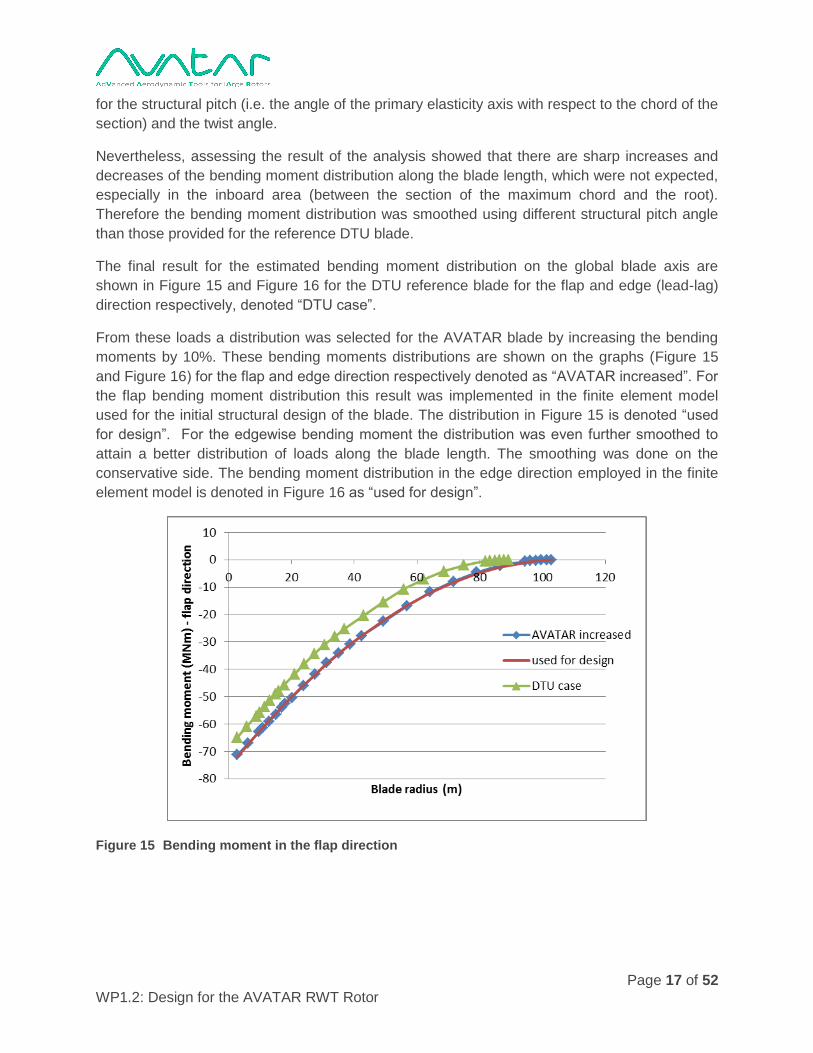
The final result for the estimated bending moment distribution on the global blade axis are
shown in Figure 15 and Figure 16 for the DTU reference blade for the flap and edge (lead-lag)
direction respectively, denoted “DTU case”.
From these loads a distribution was selected for the AVATAR blade by increasing the bending
moments by 10%. These bending moments distributions are shown on the graphs (Figure 15
and Figure 16) for the flap and edge direction respectively denoted as “AVATAR increased”. For
the flap bending moment distribution this result was implemented in the finite element model
used for the initial structural design of the blade. The distribution in Figure 15 is denoted “used
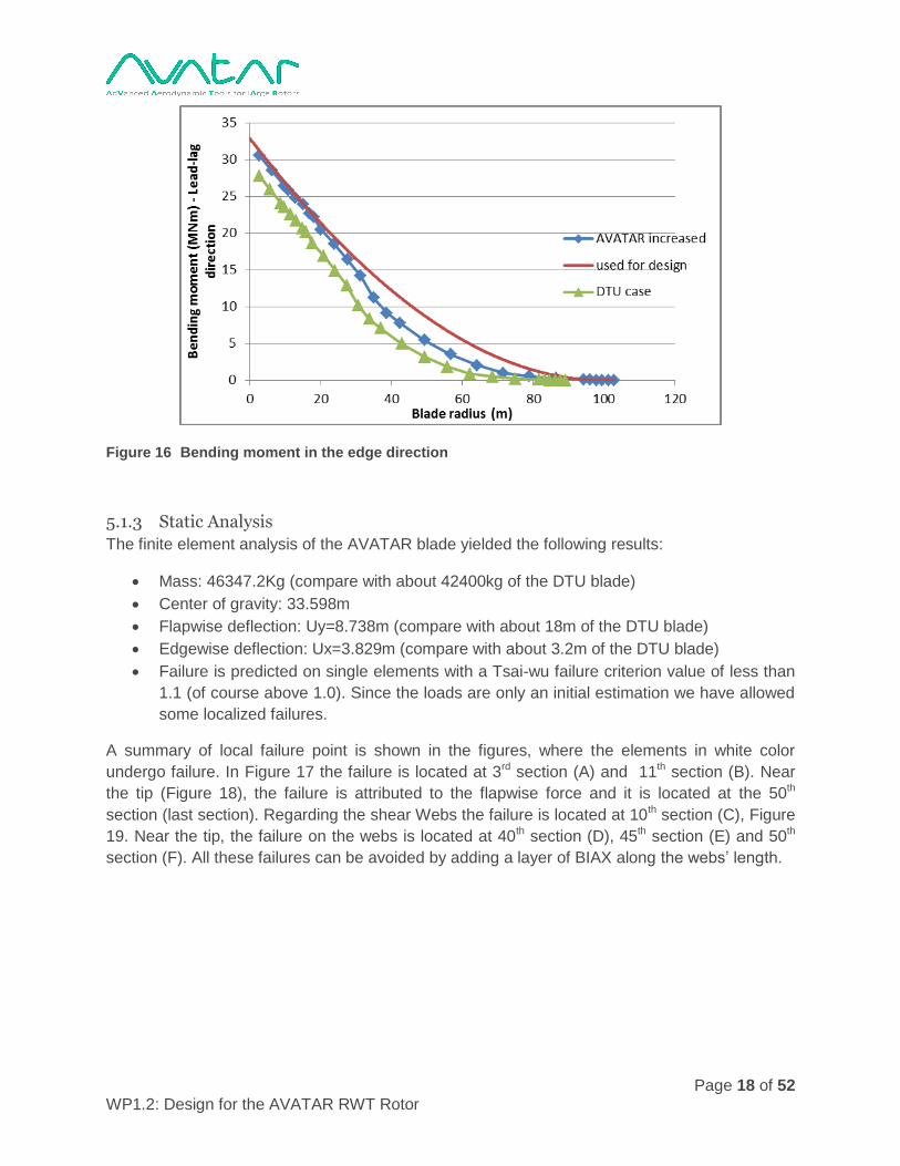
for design”. For the edgewise bending moment the distribution was even further smoothed to
attain a better distribution of loads along the blade length. The smoothing was done on the
conservative side. The bending moment distribution in the edge direction employed in the finite
element model is denoted in Figure 16 as “used for design”.
Figure 15 Bending moment in the flap direction
Page 18 of 52 WP1.2: Design for the AVATAR RWT Rotor
Figure 16 Bending moment in the edge direction
5.1.3 Static Analysis
The finite element analysis of the AVATAR blade yielded the following results:
Mass: 46347.2Kg (compare with about 42400kg of the DTU blade)
Center of gravity: 33.598m
Flapwise deflection: Uy=8.738m (compare with about 18m of the DTU blade)
Edgewise deflection: Ux=3.829m (compare with about 3.2m of the DTU blade)
Failure is predicted on single elements with a Tsai-wu failure criterion value of less than
1.1 (of course above 1.0). Since the loads are only an initial estimation we have allowed
some localized failures.
A summary of local failure point is shown in the figures, where the elements in white color
undergo failure. In Figure 17 the failure is located at 3rd section (A) and 11th section (B). Near
the tip (Figure 18), the failure is attributed to the flapwise force and it is located at the 50th
section (last section). Regarding the shear Webs the failure is located at 10th section (C), Figure
19. Near the tip, the failure on the webs is located at 40th section (D), 45th section (E) and 50th
section (F). All these failures can be avoided by adding a layer of BIAX along the webs’ length.

Page 19 of 52 WP1.2: Design for the AVATAR RWT Rotor
Figure 17 Local failure points (Tsai-Wu)
Figure 18 Local failure points (Tsai-Wu)
x
y
z
A
B
x
y
z

Page 20 of 52 WP1.2: Design for the AVATAR RWT Rotor
Figure 19 Local failure points (Tsai-Wu)
Figure 20 Local failure points (Tsai-Wu)
x y
z
C
B
x y
z
E
B
F
B
D
B

Page 21 of 52 WP1.2: Design for the AVATAR RWT Rotor
Figure 21 Strain distribution (EXX)
Figure 22 Strain distribution (EYY) x
y
z
x
y
z
x
y
z

Page 22 of 52 WP1.2: Design for the AVATAR RWT Rotor
Figure 23 Strain distribution (EXY)
x
y
z
x
y
z
x
y
z

Page 23 of 52 WP1.2: Design for the AVATAR RWT Rotor
5.1.4 Modal Analysis
The results of the natural frequencies by the modal analysis performed (using the 3-D shell
element model) are given below. Note that the rotating frequency of the wind turbine is
1P=0.16Hz.
§ 1st Eig: 0.639Hz (Edge)
§ 2nd Eig.: 0.820Hz (Flap)
§ 3rd Eig.: 1.904Hz (Edge)
§ 4th Eig.: 2.198Hz (Flap)
§ 5th Eig.: 4.045Hz (Possibly coupled)
The first 5 eigenmodes of the AVATAR blade are shown in the figure below.
The flapwise direction is the Y-direction (from suction to pressure side)
Figure 24 Eigenmodes for the blade (1-2 top row, 3-4-5 bottom row)
5.1.5 Buckling Analysis
The first three buckling modes correspond to the same buckling load factor of 1.786 which is
greater than the INNWIND.EU DTU blade (1.75).
These modes are located between between 45.52m – 60.05m on the suction side of the blade
mostly affecting the SPAR CAP elements.
Due to the sensitivity in the buckling analysis (on the spar caps) we have incorporated balsa in
the lamination sequence between the carbon layers. This solution provided results with a
minimum increase on mass and keeping the rest of the properties within required boundaries.
This is not a preferred solution, due to difficulties in manufacturability, but it was used as an
x
y

Page 24 of 52 WP1.2: Design for the AVATAR RWT Rotor
initial solution. In a production blade there are numerous ways to overcome local buckling that
are better suited to production techniques.
The following two figures illustrate the 1st buckling mode of the blade, which is located between
45.52m – 60.05m. The respective elements of the webs are NOT subject to buckling.
Figure 25 Buckling results (a)
Figure 26 Buckling results (b)
5.1.6 Mass & Stiffness Distribution
The mass/stiffness distribution along the blade is provided in an excel file (AVATAR WP1
participants, 2015) for 51 sections along the blade. Note that the z-axis for the properties
distribution corresponds to the global blade axis from trailing to leading edge, while the y-axis is
x
y
z
x
y
z

Page 25 of 52 WP1.2: Design for the AVATAR RWT Rotor
again the global blade axis from the compressive side (suction) to the tensile side (pressure) of
the blade.
An example for section at 25.0m is shown with the relevant axis in Figure 27. On this figure also
the elastic centre is shown as an example.
Figure 27 Conventions used in the geometry description
5.2 Redesign of the blade The initial design demonstrated the possibility to construct a lightweight blade at the required
size; however some undesirable properties of the resulting solution needed to be addressed in
order to have a more realistic solution. The identified issues were related to:
Small torsional rigidity. As a result of this there was substantial twist of the blade (3-3.5° at the
tip, compared to 1-1.5° for the INNWIND.EU blade). The increased twist was not a
problem per-se, as it resulted in alleviation of the blade loads, but the resulting power
curve was inferior to the one predicted at the design stage. While performance was
still better than the INNWIND.EU blade, the difference was not as big as expected. It
was therefore decided to increase the blade torsional stiffness in order to rectify this.
Placement of eigenfrequencies. While there was no immediate interaction with the 3P/6P
frequencies, the margin from the 4P frequency was too small for the initial blade. This
resulted in undesirable dynamic behavior, based on the initial aeroelastic simulations.
Large flapwise stiffness. Replacing the glass construction with carbon fiber spars resulted in a
fundamentally different dynamic response of the blade. As a result of the change in
relative stiffness between flap and edge directions, the 1st eigenfrequency now
corresponds to an edge mode with the second one corresponding to a flap mode.
This change is unusual, but not necessarily a problem. The real problem is related to
the fatigue loads calculated during the initial evaluation of the blade. During normal

Page 26 of 52 WP1.2: Design for the AVATAR RWT Rotor
operation the average bending moments were comparable to the INNWIND.EU blade,
but the spikes from wind speed variations were substantially higher. The reason is
obviously that the smaller deflections of the blade result in larger forces in order to
absorb the same amount of energy.
The combination of these issues led to a decision for a reevaluation of the structural
characteristics of the blade.
Table 5 Basic structural properties of final AVATAR blade
In the following results we make reference to three different blade structural designs
r0 is the initial blade design
Page 27 of 52 WP1.2: Design for the AVATAR RWT Rotor
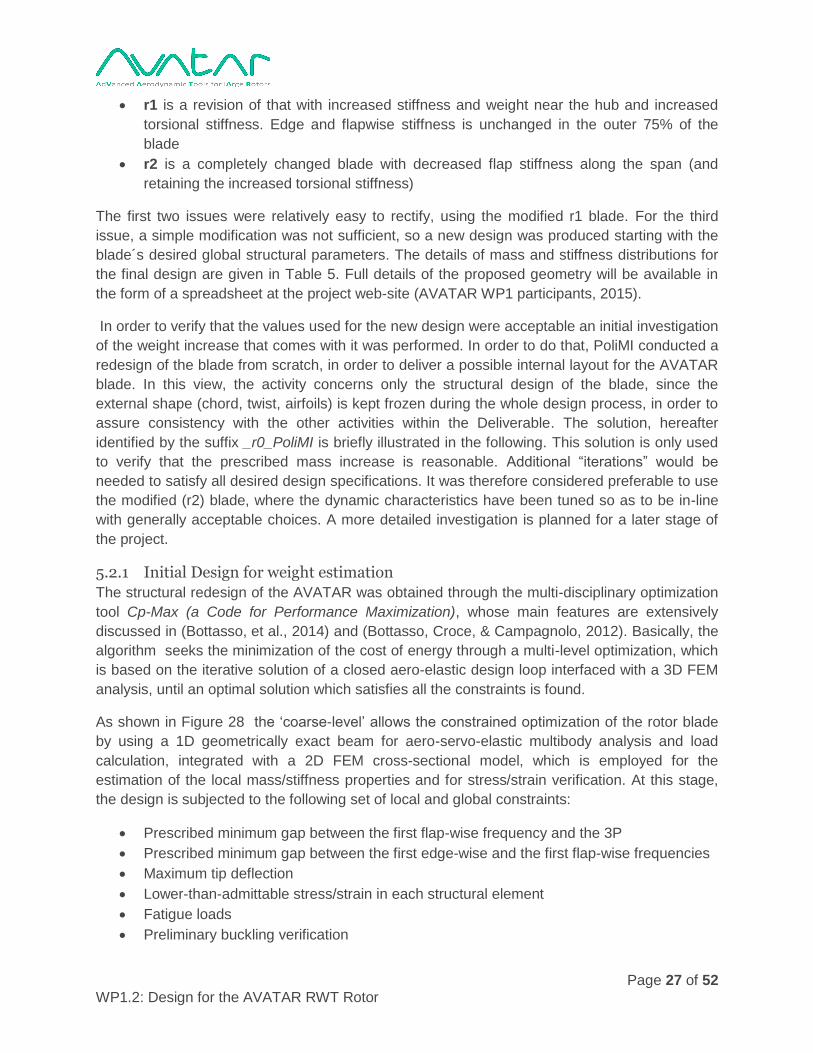
r1 is a revision of that with increased stiffness and weight near the hub and increased
torsional stiffness. Edge and flapwise stiffness is unchanged in the outer 75% of the
blade
r2 is a completely changed blade with decreased flap stiffness along the span (and
retaining the increased torsional stiffness)
The first two issues were relatively easy to rectify, using the modified r1 blade. For the third
issue, a simple modification was not sufficient, so a new design was produced starting with the
blade´s desired global structural parameters. The details of mass and stiffness distributions for
the final design are given in Table 5. Full details of the proposed geometry will be available in
the form of a spreadsheet at the project web-site (AVATAR WP1 participants, 2015).
In order to verify that the values used for the new design were acceptable an initial investigation
of the weight increase that comes with it was performed. In order to do that, PoliMI conducted a
redesign of the blade from scratch, in order to deliver a possible internal layout for the AVATAR
blade. In this view, the activity concerns only the structural design of the blade, since the
external shape (chord, twist, airfoils) is kept frozen during the whole design process, in order to
assure consistency with the other activities within the Deliverable. The solution, hereafter
identified by the suffix _r0_PoliMI is briefly illustrated in the following. This solution is only used
to verify that the prescribed mass increase is reasonable. Additional “iterations” would be
needed to satisfy all desired design specifications. It was therefore considered preferable to use
the modified (r2) blade, where the dynamic characteristics have been tuned so as to be in-line
with generally acceptable choices. A more detailed investigation is planned for a later stage of
the project.
5.2.1 Initial Design for weight estimation
The structural redesign of the AVATAR was obtained through the multi-disciplinary optimization
tool Cp-Max (a Code for Performance Maximization), whose main features are extensively
discussed in (Bottasso, et al., 2014) and (Bottasso, Croce, & Campagnolo, 2012). Basically, the
algorithm seeks the minimization of the cost of energy through a multi-level optimization, which
is based on the iterative solution of a closed aero-elastic design loop interfaced with a 3D FEM
analysis, until an optimal solution which satisfies all the constraints is found.
As shown in Figure 28 the ‘coarse-level’ allows the constrained optimization of the rotor blade
by using a 1D geometrically exact beam for aero-servo-elastic multibody analysis and load
calculation, integrated with a 2D FEM cross-sectional model, which is employed for the
estimation of the local mass/stiffness properties and for stress/strain verification. At this stage,
the design is subjected to the following set of local and global constraints:
Prescribed minimum gap between the first flap-wise frequency and the 3P
Prescribed minimum gap between the first edge-wise and the first flap-wise frequencies
Maximum tip deflection
Lower-than-admittable stress/strain in each structural element
Fatigue loads
Preliminary buckling verification

Page 28 of 52 WP1.2: Design for the AVATAR RWT Rotor
Once the coarse level optimization is completed, the optimal solution is then tested with a ‘fine-
level’ 3D FEM model, in order to identify possible shortcomings of the design, in particular for
what concern the buckling, and to obtain a refined estimation of the non-structural mass.
The improved results obtained at the fine-level are then included in the following coarse-level
iteration through a modification of the constraints.
Figure 28 Multi-level optimization
5.2.1.1 Internal blade layout
The structural model of the AVATAR_r0_PoliMI is based on the typical cross-sectional layout
reported in Figure 29, which illustrates the position of the main elements within the section. In
addition to them, a root reinforcement is defined in the region close to the hub and a third web is
present in the mid part of the blade. Table 6 lists all the 9 structural members which are defined
for this analysis, together with the non-dimensional coordinate η where each member starts and
ends. The two 800mm-wide spar caps start at η=0.05 and their width is held constant along the
entire span. However, as illustrated in Figure , a transitional region is defined between η=0.0
and η=0.05: here the spar is gradually extended in order to embrace the root cylinder and

Page 29 of 52 WP1.2: Design for the AVATAR RWT Rotor
simultaneously blended with the root reinforcement, in order to ensure a continuous distribution
of material and a smooth transition between the root solution and the rest of the blade.
Each structural element is made up of specific materials, whose properties are taken from
(Lekou, 2014) and reported in Table 7. As specified in the same report, the design of AVATAR
is based on the usage of carbon fibers (CF) in the spar. Here, for consistency, the unidirectional
carbon fiber is assigned also to the root reinforcement, in order to avoid sharp variations of the
structural properties. The design of the other elements, like for example the external shell, the
webs and the LE-TE reinforcements is based on glass-fibers composites (GF).
Figure 29 Cross-sectional arrangement of the structural elements
Figure 30 Planform view of the blade

Page 30 of 52 WP1.2: Design for the AVATAR RWT Rotor
ID Element ηStart ηEnd Material(s)
1 Shell 0.0 1.0 Triaxial, Balsa 2 Suction side spar cap 0.05 0.9812 Unidirectional (CF) 3 Aft shear web 0.05 0.9812 Biaxial, Balsa 4 Pressure side spar cap 0.05 0.9812 Unidirectional (CF) 5 Rear shear web 0.05 0.9812 Biaxial, Balsa 6 LE reinforcement 0.15 0.95 Unidirectional (GF), Balsa 7 TE reinforcement 0.15 0.95 Unidirectional (GF), Balsa 8 Root reinforcement 0.0 0.65 Unidirectional (CF) 9 Third web 0.22 0.95 Triaxial
Table 6 Structural members
TRIAXIAL UNIAXIAL (CF) UNIAXIAL (GF) BIAXIAL
E11 [GPa] 21.790 115.0 41.630 13.920
E22 [GPa] 14.670 7.560 14.930 13.920
ν12 [-] 0.478 0.300 0.241 0.533
G12 [GPa] 9.413 3.960 5.047 11.500
ρ [Kg/m3
] 1845 1578 1915 1845 σ
11_Ten [MPa] 480.4 1317.60 876.1 223.2
σ11_Comp
[MPa] 393.0 620.13 625.8 209.2 σ
22_Ten [MPa] 90.4 21.88 74.03 223.2
σ22_Comp
[MPa] 152.7 76.25 189.4 209.2 τ
12 [MPa] 114.0 45.53 56.58 140.3
Table 7 Properties of the composite materials
In addition to the design of the structural elements, several contributions to the non structural
mass are taken into account. These are summarized in Table 8 and Table 9.
BALSA PAINT ADHESIVE
E [Pa] 0.05e+09 1.00 4.56e+06
G [Pa] 0.15e+09 0.384 1.45e+06
ρ [Kg/m3
] 110 1400 1100
σ11_Ten
[MPa] 0.694 10.0 61.5
σ11_Comp
[MPa] 0.4 10.0 65.3
τ12 [MPa] 0.307 10.0 36.6
Table 8 Properties of balsa, paint and adhesive
Type Element Units Value
Linear NSM
Page 31 of 52 WP1.2: Design for the AVATAR RWT Rotor
Glue mass shear web [kg/m] 2.30 Glue mass LE, TE [kg/m] 2.88 Lightning system [kg/m] 0.50 Bonding plies shear web [kg/m] 3.90 Surface NSM Resin uptake shell [kg/m^2] 2.50 Resin uptake shear web [kg/m^2] 0.80
Table 9 Non-structural mass
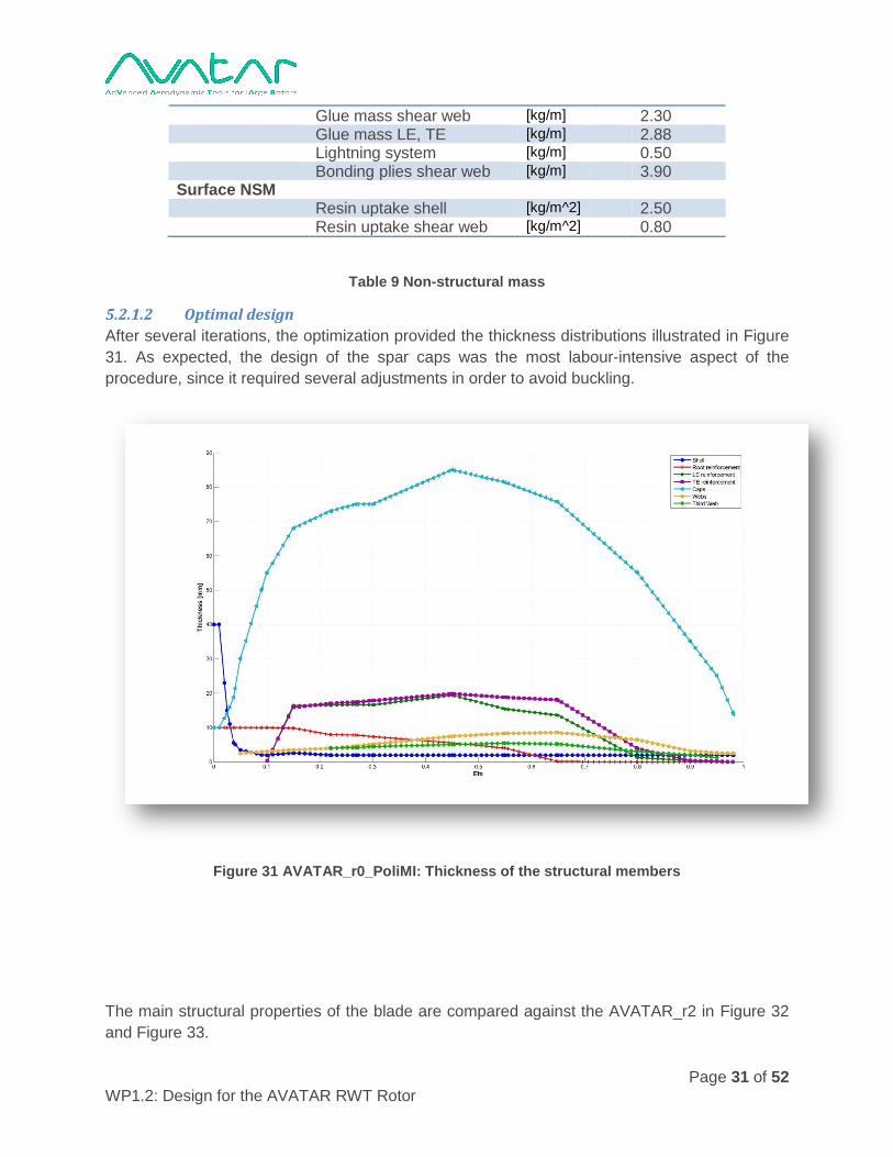
5.2.1.2 Optimal design
After several iterations, the optimization provided the thickness distributions illustrated in Figure
31. As expected, the design of the spar caps was the most labour-intensive aspect of the
procedure, since it required several adjustments in order to avoid buckling.
Figure 31 AVATAR_r0_PoliMI: Thickness of the structural members
The main structural properties of the blade are compared against the AVATAR_r2 in Figure 32
and Figure 33.

Page 32 of 52 WP1.2: Design for the AVATAR RWT Rotor
Figure 32 AVATAR_r0_PoliMI: Flap-wise (up) and edge-wise (down) stiffness distribution
Figure 33 AVATAR_r0_PoliMI: mass per unit length distribution
5.2.1.3 Constraints
The following figures illustrate the value of the constraints for each structural element along the
blade. It must be recalled that a negative value of the bars implies that the constraint is satisfied.

Page 33 of 52 WP1.2: Design for the AVATAR RWT Rotor
Shell
Suction side spar cap
Forward shear web
LE - reinforcement
TE - reinforcement
Root reinforcement
Figure 34 AVATAR_r0_PoliMI: Value of the constraints along the blade
In addition, Table 10 lists, for each element, the most active constraint which affects the design.

Page 34 of 52 WP1.2: Design for the AVATAR RWT Rotor
ID Element Most active design constraint
1 Shell Fatigue 2 Suction side spar cap Buckling 3 Forward shear web Fatigue 4 Pressure side spar cap Buckling 5 Rear shear web Fatigue 6 LE reinforcement Frequencies separation 7 TE reinforcement Frequencies separation 8 Root reinforcement Stress/strain 9 Third web None
Table 10 AVATAR_r0_PoliMI: Active constraints
5.2.1.4 Tip deflection
The maximum tip deflection for the AVATAR_r0_PoliMI was d=8.86 m, and occurred on blade 3
during the DLC 2.3 (EOG plus occurrence of fault), simulated at 25 m/s, which implies that the
maximum tip deflection is not an active constraint for the design.
5.2.1.5 Eigenfrequencies
The following clamped-blade eigenfrequencies were identified:
Mode Frequency [Hz] Type
1 0.665 Flap 2 0.777 Edge 3 1.91 Flap 4 2.31 Edge 5 4.04 Flap
Table 11 AVATAR_r0_PoliMI: First 5 eigenfrequencies of the clamped blade
And the corresponding modal shapes are illustrated in Figure 35. Considering an operating
rotational speed equal to 9.6 rpm, the first flapwise frequency is 38% higher than the 3P. At the
same time, the first edgewise frequency is 16.8% higher than the first flapwise.

Page 35 of 52 WP1.2: Design for the AVATAR RWT Rotor
1. First flap-wise mode at f=0.665 Hz
2. First edge-wise mode at f=0.777 Hz
3. Second flap-wise mode at f=1.91 Hz
4. Second edge-wise mode at f=2.31 Hz
Figure 35 AVATAR_r0_PoliMI: modes of the clamped blade
5.2.1.6 Mass
The total blade mass of the AVATAR_r0_PoliMI is 48118 kg. Table 12 shows the contribution of
each structural element to the total mass, as well as the contributions of the various non-
structural masses.

Page 36 of 52 WP1.2: Design for the AVATAR RWT Rotor
Element Mass [kg] % of total mass
Spar caps 16439 34.16
Root reinforcement 6628 13.77
Shell 6901 14.34
LE - TE reinforcements 4854 10.09
Shear webs 2866 5.96
Third web 110 0.23
Total structural mass: 37798 78.55
Surface NSM 2180 4.53
Linear NSM 1980 4.11
Paint 735 1.53
Core (webs) 1619 3.36
Core (shell) 2429 5.05
Core (LE-TE reinforcements) 1377 2.86
Total NSM: 10320 21.45
Total blade mass: 48118 100.0
Table 12 AVATAR_r0_PoliMI: mass contributions from individual elements
5.2.1.7 Loads envelope
The DLC considered during the design of the AVATAR_r0_PoliMI are listed in Table 13Table .
These cases were chosen in order to include the worst-case scenario for what concerns both
the maximum tip displacement and the loads.
Case DLC Wind model Number of simulations Wind speed
Power production
1.1 NTM 12 Vcutin ≤ V ≤ Vcutout 1.3 ETM 12 Vcutin ≤ V ≤ Vcutout
1.4 ECD 16 Vr-2 ≤ V ≤ Vr+2 Production plus fault
2.3 EOG Vr-2 ≤ V ≤ Vcutout
Parked 6.2 EWM-50 12 50 m/s
Table 13 Considered DLC
The loads envelope at the blade root for the three blades is reported in Table 14. The
corresponding reference system is sketched in Figure 36.

Page 37 of 52 WP1.2: Design for the AVATAR RWT Rotor
Figure 36 Blade coordinate system
In-plane
Bending Mx
Out-of-plane
Bending My
Combined
Bending Mxy
Torsion
Mz Blade DLC
[kNm] [kNm] [kNm] [kNm] - -
Max 65441 -54245 85000 255 2 DLC23_voa
Min -50310 -2768 50386 -165 3 DLC23_voa
Max -4026 81766 81865 -80 2 DLC11_25a
Min 39226 -80679 89709 206 3 DLC23_voa
Max 39226 -80679 89709 206 3 DLC23_voa
Max 59214 -63959 87161 466 3 DLC23_vr+2a
Min 2434 -29475 29575 -902 3 DLC14_vrplusa
Table 14 AVATAR_r0_PoliMI: Loads envelope at blade root for the three blades
The loads envelope at the tower top is reported in Table 15 following the coordinate system
sketched in Figure 37, while the load envelope for the hub is reported in Table 16, following the
coordinate system of Figure 38

Page 38 of 52 WP1.2: Design for the AVATAR RWT Rotor
Figure 37 tower top coordinate system
Side-side
Bending Mx
Fore-aft
Bending My
Combined
Bending Mxy
Torsion
Mz DLC
[kNm] [kNm] [kNm] [kNm] -
Max 27915 6170 28589 17191
DLC62_ID_T_YMdeg-
90a
Min -13186 3326 13599 -9662
DLC62_ID_T_YMdeg90
a
Max 13596 93874 94853 -28881 DLC11_25a
Min -462 -83445 83446 7604 DLC23_vr+2a
Max 13596 93874 94853 -28881 DLC11_25a
Max 19230 3487 19543 46616 DLC11_25a
Min -4291 -35017 35279 -68335 DLC23_voa
Table 15 AVATAR_r0_PoliMI: Loads envelope at tower top

Page 39 of 52 WP1.2: Design for the AVATAR RWT Rotor
Figure 38 Hub coordinate system
Fx My Mz Myz DLC
[kN] [kNm] [kNm] [kNm] -
Max 3212 -35790 -10723 37362 DLC23_voa
Min -3621 57118 -2315 57165 DLC23_vr+2a
Max -3594 58613 7733 59121 DLC23_vr+2a
Min 998 -95442 -21124 97752 DLC11_25a
Max 2067 -5556 44989 45330 DLC11_25a
Min -2275 21071 -66248 69518 DLC23_voa
Max 1078 -95140 -27667 99082 DLC11_25a
Table 16 AVATAR_r0_PoliMI: Loads envelope at hub

Page 40 of 52 WP1.2: Design for the AVATAR RWT Rotor
6 Loads and Stability
6.1 Test Cases For the initial evaluation, a limited set of test cases were used, while a more complete set will be
used for the final evaluation. The tests that were performed included
Steady operation for rigid and flexible blades, in order to verify the design power curve of
the wind turbine
Stability analysis, including uncoupled and coupled eigen-frequencies of the blades
Unsteady simulations of the operation during speed-up and speed-down, in order to
identify obvious problems and verify the suitability of the controller used for the wind
turbine
Unsteady operation in normal conditions (DLC1.2), in order to get a first estimate of the
expected fatigue loads and displacements in normal conditions
Some partners performed additional tests, based on other Design Load Cases, as specified by
the IEC standards. The tests described in this section have been performed by all three
partners, though in some cases only indicative results from one or two are presented, as the
results were similar. A much more detailed analysis including a full set of DLC cases is to be
reported in D1.3, where comparisons between the results are made.
6.2 Computational Tools Three different computational methods were independently used to assess the aeroelastic
performance of the reference blade.
DTU made use of HAWC2 (Horizontal Axis Wind turbine simulation Code 2nd generation) which
is an aeroelastic code intended for calculating wind turbine response in time domain.
The core of the code was developed mainly within the years 2003-2007, by the Aeroelastic
Design Research Program at DTU Wind Energy, DTU Risø Campus in Denmark. HAWC2 is
developed and distributed by DTU Wind Energy and has been used in numerous research
projects and industrial applications. HAWC2 has a large number of users and is used both for
design and verification purposes.
HAWC2 is able to simulate wind turbines in time response with following properties:
Normal onshore with 1,2, 3 or more blades
Pitch and (active) stall controlled wind turbines
Guyed support structures
Offshore turbines on monopoles, tripods or jackets
Floating turbines with mooring lines
Multiple rotors in one simulation
Multibody formulation that can handle multiple degrees of freedom (like blade torsion)
Detailed aerodynamic model that includes:

Page 41 of 52 WP1.2: Design for the AVATAR RWT Rotor
o Dynamic stall models: Stig Øye model, a modified Beddoes-leishmann model
and a model for ATEF (Active Trailing Edge Flaps)
o Skew inflow model
o Shear effects on the induction
o Dynamic inflow model
Hydrodynamic model based on Morrison’s equation
Water Kinematics that includes:
o Currents
o Linear airy waves
o Irregular airy waves
o Deterministic irregular waves
o Stream function wave
Wind, turbulence and wake models:
Control interface performed through DLL´s (Dynamic Link Library)
Default controller provided with a pitchregulated variable speed controller
Eigenvalue analysis at standstill
PoliMi made use of the software Cp-Lambda (Code for Performance, Loads and Aeroelasticity
by Multi-Body Dynamic Analysis), based on a finite-element multibody formulation.
The multi-body approach is based on the full finite-element method, i.e., no modal-based
reduction is performed on the deformable components of the structure. Cartesian coordinates
are used for the description of all entities in the model, and all degrees of freedom are referred
to a single inertial frame; the formulation handles arbitrarily large three-dimensional rotations.
The turbine blades, the tower and the shaft are modeled using geometrically exact, composite-
ready beams. The formulation models beams of arbitrary geometry, including curved and
twisted reference lines, and accounts for axial, shear, bending, and torsional stiffness. Joints are
modeled through holonomic or nonholonomic constraints, as appropriate, that are enforced by
means of Lagrange multipliers using the scaled augmented Lagrangian method. All joints can
be equipped with internal springs, dampers, backlash, friction, and power loss models, which
are used among other things to account for such effects in the gear-box and drive-train.
The blade pitch system response is modeled with a second order system, while the response of
the generator by a first order one; both actuator models receive commanded signals by the
supervision and feedback controllers.
Lifting lines can be associated with beam elements and their geometric description is given in
terms of three-dimensional twisted curves; for generality of the implementation, these
aerodynamic reference curves are distinct from the structural reference ones they are
associated with. The lifting lines are based on classical two-dimensional blade element theory,
and account for the aerodynamic center offset, twist, sweep, and unsteady corrections. At a
number of span-wise stations along each lifting line, the aerodynamic characteristics of the
airfoil used at that location are given using look-up tables, which store for a given number of
angles of attack and Reynolds numbers the values of the sectional lift, drag, and moment
coefficients. Lifting lines are used here to model the aerodynamic characteristics of the blades,

Page 42 of 52 WP1.2: Design for the AVATAR RWT Rotor
but also of the tower and of the nacelle. An inflow element can be associated with the blade
lifting lines so as to model the rotor inflow effects; the code implements the Peters–He dynamic
inflow wake model and a classical blade-element momentum (BEM) model based on the
annular stream-tube theory with wake swirl. Tip and hub loss models are also considered.
Wind is modeled as the sum of a steady state mean wind and a perturbation wind, accounting
for turbulence and/or gusts. The deterministic component of the wind field implements the
transients (i.e. gusts), the exponential and logarithmic wind shear models, and the tower
shadow effects, which include the potential flow model for a conical tower, the downwind
empirical model or an interpolation of these two models. The stochastic component of the wind
field is computed according to the Mann or Kaimal turbulence models. The turbulent wind is pre-
computed before the beginning of the simulation for an assigned duration of time and for a user-
specified two-dimensional grid of points.
During the simulation, the current position of each airstation is mapped to this grid, and the
current value of the wind is interpolated in space and time from the saved data. The multi-body
formulation used in this effort leads to a set of non-linear partial differential algebraic equations.
Spatial discretization of the flexible elements of the model using the finite-element method yields
a system of differential algebraic equations in time that are solved using an implicit integration
procedure that is nonlinearly unconditionally stable. The implicit nature of the scheme allows for
the use of large time steps and is more appropriate than explicit schemes for the typical
dynamics of rotor systems. At each time step, the resulting non-linear system of equations is
solved using a quasi-Newton scheme. The time-step length is adjusted based on an error
indicator. The code supports static and transient analyses, and the computation of
eigenfrequencies and eigenmodes about deformed equilibrium configurations.
CENER has used GL GH BLADED v4.4 for the calculations into D1.2. GL GH BLADED is a
BEM based dynamic load calculation program for multibody structures with coupled
aerodynamic and hydrodynamic loads. BLADED calculates the structure dynamic with a
multibody-dynamic-approach. The components such as blades and tower are modelled from
single, linear and flexible elements whose deformation is determined by modal analyses. This is
done by a linear combination of the calculated eigenmodes resulting from a finite elements
method calculation. The aerodynamic forces are calculated with the blade element momentum
theory. In addition, BLADED is able to simulate a wake behind the rotor and dynamic stall.
6.3 Results
6.3.1 Power Curve Verification
For these tests the operation of the blade under constant (non-dynamic) conditions was
examined for stiff (theoretical) and flexible (actual) blade. For the stiff blade, the results closely
matched the predicted design performance (as expected, since they are both based on BEM
modeling). For the flexible blade there was a reduction in power production, as a result of the
blade twist. As discussed in the previous section, this was initially quite large, but for the
redesigned (r2) blade, with increased torsional stiffness, the performance was improved. In all
cases there was an improvement in energy yield compared to the INNWIND.EU blade. A
detailed investigation of the calculated power curve is performed as part of WP2.

Page 43 of 52 WP1.2: Design for the AVATAR RWT Rotor
Figure 39 Comparison of power curves for the various configurations and comparison with INNWIND.EU rotor stability analysis
The first test performed was the estimation of the blade natural frequencies, without taking into
account rotation effects. The results from this are summarized in Table 17, showing a generally
good agreement between results obtained with different calculation methods, and a substantial
separation of the prevailing eigenfrequencies.
Table 17 Blade eigenfrequencies
CENER PoliMI
1st flap 0.684 (4.27P) 0.6733 (4.21P) 1st edge 0.901 (5.63P) 0.8861 (5.54P) 2nd flap 1.883 (11.77P) 1.8335 (11.46P) 2nd edge 2.606 (16.29P) 2.4912 (15.57P) 5th 3.852 (24.05P) 3.6884 (23.05P)
The second step in the stability analysis was the derivation of the Campbell diagrams for the
operating envelope of the proposed wind turbine. Again, no serious problems were identified
with the final design.

Page 44 of 52 WP1.2: Design for the AVATAR RWT Rotor
Figure 40 AVATAR RWT Campbell diagram (CENER)
Figure 41 AVATAR RWT Campbell diagram (PoliMi)

Page 45 of 52 WP1.2: Design for the AVATAR RWT Rotor
Figure 42 AVATAR RWT Campbell diagram (DTU)
6.3.2 Speed-up/Speed-down simulations
A ramp of wind speeds from 0 to 25m/s was used to test the behavior of the controller and
ensure that there was not an undesirable behavior in transitional regions. The results show that
there are some excursions during the transitional period, but not at alarming levels. Given that
the controller has not been optimized for this wind turbine, the results are considered
satisfactory. A check of the blade deflections and torsion at tip (Figure 48) shows that the
redesigned blade displays reduced torsion and increased flapwise deflections, as intended,
compared to the earlier designs.
Figure 43 Simulation of step-up operation (CENER)

Page 46 of 52 WP1.2: Design for the AVATAR RWT Rotor
Figure 44 Simulation of step-down operation (CENER)
Figure 45 Simulation of step-up operation (PoliMi)
Figure 46 Simulation of step-down operation (PoliMi)

Page 47 of 52 WP1.2: Design for the AVATAR RWT Rotor
Figure 47 Simulation of step-up and step-down operation (DTU)
Figure 48 Changes in torsion and deflection between the three designs (PoliMi)
6.3.3 Unsteady operation
For the unsteady operation, a series of runs for different wind speeds were performed by the
participating partners.

Page 48 of 52 WP1.2: Design for the AVATAR RWT Rotor
Figure 49 Displacements for DLC1.2 at different wind speeds (CENER)
Figure 50 Bending moments for DLC1.2 at different wind speeds (CENER)

Page 49 of 52 WP1.2: Design for the AVATAR RWT Rotor
Figure 51 Deflection and bending moment at 11m/s (DTU)
As seen in e.g. Table 18. The proposed blade is still stiffer than the equivalent INNWIND.EU
blade, resulting in smaller deflections (out-of-plane), while the deflections in-plane are slightly
increased as a result of the increased length and weight.
Table 18 Max calculated values of deflection and loads during normal operation (DLC1.2) (CENER)
Blade Tip Deflection (Out of Plane) 8.05m Blade Tip Deflection (In Plane) 2.23m Blade Tip Torsion (degs) 2.52 Blade Root Bending Moment (Out of Plane) 50432kNm Blade Root Bending Moment (Out of Plane) 21311kNm
Table 19 Max. loads based on all DLC cases used (PoliMi)
Page 50 of 52 WP1.2: Design for the AVATAR RWT Rotor
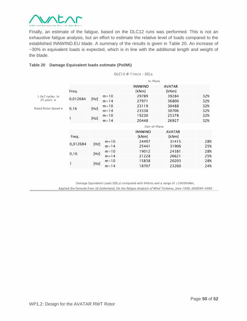
Finally, an estimate of the fatigue, based on the DLC12 runs was performed. This is not an
exhaustive fatigue analysis, but an effort to estimate the relative level of loads compared to the
established INNWIND.EU blade. A summary of the results is given in Table 20. An increase of
~30% in equivalent loads is expected, which is in line with the additional length and weight of
the blade.
Table 20 Damage Equivalent loads estimate (PoliMi)

Page 51 of 52 WP1.2: Design for the AVATAR RWT Rotor
7 Conclusions The initial design process and the resulting blade and wind turbine parameters for a reference
high speed wind turbine have been presented in the report. The resulting values will be used for
the work performed for the other work packages of the AVATAR project.
The main drivers for the design were to produce a blade that would
a) Stretch the limits of the computational methods currently in use
b) Have a performance benefit compared to the INNWIND.EU blade, on which it is based (so
that there is justification for the proposed design direction)
c) Provide a reasonable basis for further design changes in the following stages of the project.
The current blade is not necessarily the best solution for the problem in hand. As already
discussed, there are different ways to achieve the lower power density that is required for the
low induction rotor. The best way is probably to use low-lift airfoils, e.g. airfoils having their
maximum k = CL/CD at moderate CL values. These will be evaluated at a later stage, as it was
necessary to work with existing airfoil families for the reference design. Alternatively, part of the
required reduction in 𝑐 ∙ 𝐶𝐿 could come from a reduction in chord. Smaller chords allow for better
aerodynamic performance (higher k values) and local buckling resistance but lead to heavier
and softer designs (using the same materials). Such a solution would lead to an increase in tip
deflection and would change significantly the dynamics of a large blade getting, in this case, its
first natural frequency down from 4P close to 3P.
Changing the construction materials (from glass fibre to carbon spars) can alleviate this
problem, leading to significantly stiffer (though more expensive) blades. Evidently, to get the
best compromise, the design space needs to be checked further for the 2nd stage optimum
design, in order to get the optimum combination of lift, chord and blade thickness for very large
blades.

Page 52 of 52 WP1.2: Design for the AVATAR RWT Rotor
8 References AVATAR WP1 participants. (2015, 2). AVATAR10MWReferenceWindTurbine.xls. Retrieved
from AVATAR Intranet: http://www.eera-avatar.eu
Bak, C., Zahle, F., Bitsche, R., Kim, T., Yde, A., Henriksen, L., . . . A. Natarajan, M. H. (n.d.).
Design and performance of a 10 MW wind turbine (to be accepted). J. Wind Energy.
Bottasso, C., Campagnolo, F., Croce, A., Dilli, S., Gualdoni, F., & Nielsen, M. (2014). Structural
optimization of wind turbine rotor blades by multi-level/sectional/multibody/3D FEM
analyisis. Multibody System Dynamics, Vol. 32, 87-116.
Bottasso, C., Croce, A., & Campagnolo, F. (2012). Multi-disciplinary constrained optimization of
wind turbines. Multibody System Dynamics Vol. 27, 21-53.
Chaviaropoulos, T., Beurskens H.J, M., & Voutsinas, S. (2013). Moving towards large(r) high
speed rotors – is that a good idea? EWEA Conference Proceedings. Vienna.
Griffith, D. T. (2013). The SNL-100-01 Blade: Carbod Design Studies for the Sandia 100m
Blade.
Griffith, D. T., & Ashwill, T. D. (2011). The Sandia 100-meter all-glass baseline wind turbine
blade: SNL100-00. New Mexico: Sandia National Laboratories.
IEC. (2005, August). IEC 61400-1: Wind Turbines - Part 1: Design Requirements. Standard.
Standard.
Lekou, D. (2014). Report on structural solution for a long carbon blade within AVATAR project.
CRES, Centre for Renewable Energy Sources and saving.
Stettner, M., & Chaviaropoulos, P. (2014). Reference Blade Specifications. Deliverable D1.1.