Embed Size (px)
Citation preview

Service Manual ......................................................................................... 3
Avantgarde CV / CS / CLT
© Otto Bock · 647G690=EN-01-1102

2 02/2011
Introduction1 6............................................................................................................................................................Foreword 1.1 6....................................................................................................................................................Support1.2 6........................................................................................................................................................Product overview1.3 7.........................................................................................................................................
Safety2 9......................................................................................................................................................................Explanation of warning symbols2.1 9.................................................................................................................General Safety Instructions2.2 10.......................................................................................................................
Service Work3 10.........................................................................................................................................................Instructions for Adjustment3.1 10.......................................................................................................................Required Tools and Accessories3.2 11...............................................................................................................Special features of the Avantgarde CLT3.3 11...................................................................................................Maintenance Schedule3.4 11..............................................................................................................................Assembly A: Frame3.5 12...................................................................................................................................
Replacement Work on the Frame3.5.1 12...................................................................................................Replacing the Front Frame Part3.5.1.1 12.......................................................................................Replacing the Rear Frame Part3.5.1.2 13........................................................................................Replacing the Cross-Brace/Cross-Brace Bracket3.5.1.3 14............................................................Replacing the Joint Tubes3.5.1.4 15.................................................................................................Replacing the Seat Tube Supports3.5.1.5 15...................................................................................
Retrofitting the Vertical Accessory Mount3.5.2 16........................................................................................Installation / adjustment of the anti-tipper3.5.3 17........................................................................................
Installing the anti-tipper3.5.3.1 17....................................................................................................Adjustment of the anti-tipper3.5.3.2 18.............................................................................................Replacing the Pivot Arm3.5.3.3 18...................................................................................................Replacing Anti-Tipper Rollers3.5.3.4 19...........................................................................................
Retrofitting the Transport Wheels3.5.4 19...................................................................................................Retrofitting the Horizontal Accessory Mount3.5.5 19....................................................................................Retrofitting the Tip-Assist3.5.6 20................................................................................................................Retrofitting the Crutch Holder3.5.7 20.........................................................................................................Retrofitting the Frame Pads (CS/CLT only)3.5.8 20....................................................................................
Assembly B: Footrest3.6 21................................................................................................................................Adjusting the Foot Rests/Tube Foot Rest/Foot Plates3.6.1 21.....................................................................Replacement Work on the CV Model3.6.2 21..............................................................................................
Replacing the Foot Rest3.6.2.1 21...................................................................................................Replacing the Foot Rest Bar/Swivel Segment3.6.2.2 21..................................................................Replacing the Foot Plate3.6.2.3 22..................................................................................................Replacing the Pivot Bearing3.6.2.4 22.............................................................................................Replacing the Locking Device3.6.2.5 23..........................................................................................Retrofitting the Heel Strap3.6.2.6 23................................................................................................Elevating Foot Rest with Automatic Length Adjustment3.6.2.7 23.....................................................
Retrofitting the Elevating Foot Rest3.6.2.7.1 23.................................................................Replacing the Foot Rest Bar3.6.2.7.2 23...........................................................................Replacing the Calf Pads3.6.2.7.3 24.................................................................................Replacing the Retaining Plate3.6.2.7.4 24.........................................................................
Replacement Work on the CS/CLT Model3.6.3 25.....................................................................................Replacing the Foot Rest Bar3.6.3.1 25............................................................................................Replacing the Foot Plate3.6.3.2 25..................................................................................................Replacing the Foot Plate3.6.3.3 25..................................................................................................Replacing the Tube Foot Rest3.6.3.4 25..........................................................................................
Table of contents
302/2011
Table of contents
Table of contents
Replacing the Tube Foot Rest Mounting3.6.3.5 26...........................................................................Assembly C: Seat3.7 26......................................................................................................................................
Replacing the Standard/Business Seat Upholstery3.7.1 26.........................................................................Replacing the Seat Upholstery, Adaptable3.7.2 27.....................................................................................Cleaning the Seat Upholstery3.7.3 28.........................................................................................................Cleaning the Standard Seat Cushion3.7.4 28.............................................................................................
Assembly D: Back/Push Handle3.8 28...............................................................................................................Replacement Work on the Push Handles3.8.1 28........................................................................................
Replacing the Push Handles, Standard3.8.1.1 28............................................................................Retrofitting the Telescoping Push Handles3.8.1.2 29........................................................................Retrofitting the Height-Adjustable Push Handles3.8.1.3 29...............................................................Retrofitting the Folding Push Handles3.8.1.4 30...............................................................................Replacing the Rubber Hand Grips3.8.1.5 30....................................................................................
Replacing the Back Upholstery3.8.2 30.......................................................................................................Replacing the Back Upholstery, Standard3.8.2.1 30........................................................................Replacing the Back Upholstery, Adaptable3.8.2.2 31......................................................................
Replacing the Back Tubes3.8.3 31..............................................................................................................Replacing the Angle-Adjustable Back Tubes3.8.4 32..................................................................................
Assembly E: Side Panels3.9 33...........................................................................................................................Replacement Work on the Standard Side Panel/Clothing Protector3.9.1 33...............................................
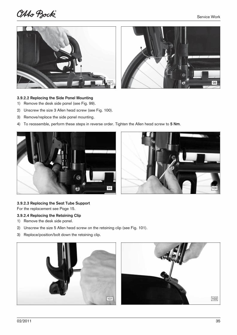
Replacing the Standard Side Panel/Clothing Protector3.9.1.1 33....................................................Replacing the Side Panel Mounting3.9.1.2 34..................................................................................
Replacement Work on the Desk Side Panel3.9.2 34....................................................................................Replacing the Desk Side Panels3.9.2.1 34.......................................................................................Replacing the Side Panel Mounting3.9.2.2 35..................................................................................Replacing the Seat Tube Support3.9.2.3 35....................................................................................Replacing the Retaining Clip3.9.2.4 35............................................................................................Replacing the Pivot Pin3.9.2.5 36.....................................................................................................Replacing the Strut3.9.2.6 36..........................................................................................................Replacing the Arm Rest Pad3.9.2.7 36............................................................................................
Assembly F: Caster Wheels3.10 36.......................................................................................................................Replacing/Changing the Installation Position of the Caster Head3.10.1 36...................................................Adjusting the Caster Wheel Journal Angle3.10.2 37......................................................................................Replacing/Changing the Installation Position of the Caster Wheels3.10.3 38................................................Replacing the Caster Fork3.10.4 39..............................................................................................................Replacing the Eccentric Disc3.10.5 39..........................................................................................................Retrofitting the Caster Fork System Frog Legs (spring-mounted)3.10.6 39....................................................Retrofitting the Caster Wheel Adapter for High/Low Seat Heights in the Front3.10.7 40...............................
Assembly G: Rear Wheels3.11 41.........................................................................................................................Adjusting the Rear Wheels/Rear Wheel Adapters3.11.1 41...........................................................................Rear Wheel Adapter, Standard3.11.2 41......................................................................................................
Replacing the Rear Wheel Adapter, Standard3.11.2.1 41..................................................................Installing the Fitting3.11.2.2 42..........................................................................................................
Shock Absorber System3.11.3 43.................................................................................................................Retrofitting the Shock Absorber3.11.3.1 43........................................................................................Installing the Fitting3.11.3.2 44..........................................................................................................
Wheelbase extension3.11.4 44......................................................................................................................Retrofitting the Wheelbase Extension3.11.4.1 44................................................................................Installing the Fitting3.11.4.2 45..........................................................................................................
Changing the Rear Wheel Camber3.11.5 45................................................................................................Maintenance Work on the Rear Wheel3.11.6 45...........................................................................................
Replacing the Tyres3.11.6.1 45..........................................................................................................Replacing the Push Rings/Adjusting the Installation Position "narrow/wide"3.11.6.2 45.....................Tensioning the Spokes/Adjusting the Out-of-Round3.11.6.3 46..........................................................
4 02/2011
Table of contents
Adjusting the Quick-Release Axle3.11.6.4 46.....................................................................................Retrofitting the Tetra Axle3.11.6.5 46.................................................................................................
Assembly H: Wheel Lock/Brake3.12 47................................................................................................................Adjusting the Knee Lever Wheel Lock/Drum Brake3.12.1 47.........................................................................Replacing the Knee Lever Wheel Lock3.12.2 47...........................................................................................Replacing the Brake Block3.12.3 48.............................................................................................................Retrofitting the Wheel Lock Lever Extension3.12.4 48...................................................................................Retrofitting the Drum Brake3.12.5 48............................................................................................................Adjusting the Drum Brake3.12.6 49...............................................................................................................
Other Accessories3.13 50.....................................................................................................................................Retrofitting a Lap Belt3.13.1 50.....................................................................................................................Retrofitting a Tray3.13.2 50...........................................................................................................................
Appendices4 50...........................................................................................................................................................Technical Data4.1 50..........................................................................................................................................
502/2011 502/2011
1 Introduction
1.1 Foreword Regular maintenance is important – it improves safety and increases the lifespan of the product. All Mobility products should be inspected and serviced once a year. However, we recommend inspecting, readjusting, and if necessary servicing the product every 6 months if the productis used frequently, by growing children, or by patients with changing clinical pictures. Only use original spare parts for all service and maintenance work. The service and maintenance tasks described hereshould only be completed by trained, qualified personnel and not by the user of the device.This service and maintenance manual refers to the respective spare parts catalogues and the instructions for use ofthe described products. Please use these documents together. Use the maintenance schedule (checklist) as a template for making copies. Retain completed maintenance schedulesand provide the customer with a copy.
Instructions for Use (qualified personnel)
Instructions for Use (User)
Avantgarde CV/CS/CLT 647G568=* 647G689=*
1.2 SupportYour national Otto Bock team will be happy to answer any technical questions. The contact addresses and telephonenumbers can be found on the back of the service manual.
6 02/2011
Introduction
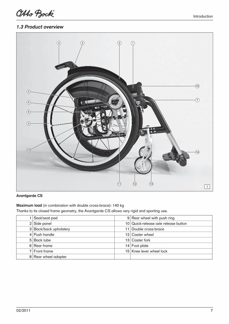
1.3 Product overview
1
Avantgarde CS
Maximum load (in combination with double cross-brace): 140 kgThanks to its closed frame geometry, the Avantgarde CS allows very rigid and sporting use.
1 Seat/seat pad 9 Rear wheel with push ring2 Side panel 10 Quick-release axle release button3 Back/back upholstery 11 Double cross-brace4 Push handle 12 Caster wheel5 Back tube 13 Caster fork6 Rear frame 14 Foot plate7 Front frame 15 Knee lever wheel lock8 Rear wheel adapter
702/2011
Introduction
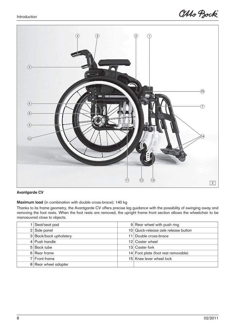
2
Avantgarde CV
Maximum load (in combination with double cross-brace): 140 kgThanks to its frame geometry, the Avantgarde CV offers precise leg guidance with the possibility of swinging away andremoving the foot rests. When the foot rests are removed, the upright frame front section allows the wheelchair to bemanoeuvred close to objects.
1 Seat/seat pad 9 Rear wheel with push ring2 Side panel 10 Quick-release axle release button3 Back/back upholstery 11 Double cross-brace4 Push handle 12 Caster wheel5 Back tube 13 Caster fork6 Rear frame 14 Foot plate (foot rest removable)7 Front frame 15 Knee lever wheel lock8 Rear wheel adapter
8 02/2011
Introduction
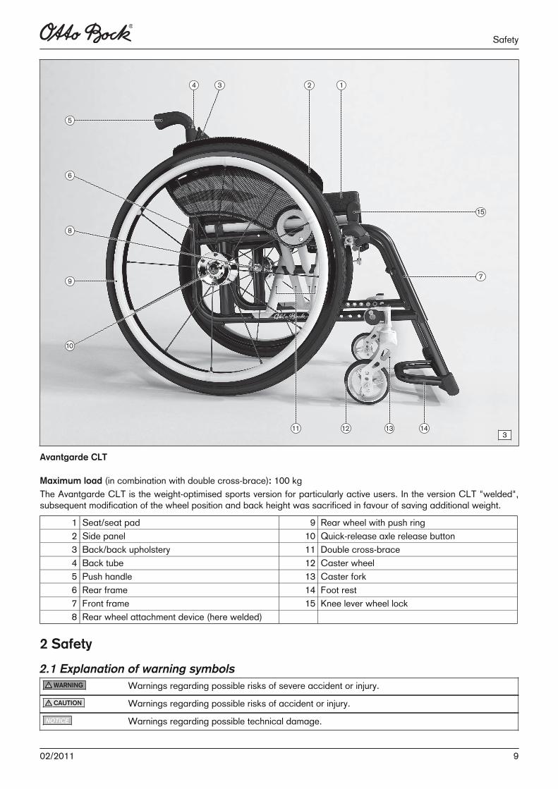
3
Avantgarde CLT
Maximum load (in combination with double cross-brace): 100 kgThe Avantgarde CLT is the weight-optimised sports version for particularly active users. In the version CLT "welded",subsequent modification of the wheel position and back height was sacrificed in favour of saving additional weight.
1 Seat/seat pad 9 Rear wheel with push ring2 Side panel 10 Quick-release axle release button3 Back/back upholstery 11 Double cross-brace4 Back tube 12 Caster wheel5 Push handle 13 Caster fork6 Rear frame 14 Foot rest7 Front frame 15 Knee lever wheel lock8 Rear wheel attachment device (here welded)
2 Safety
2.1 Explanation of warning symbolsWARNING Warnings regarding possible risks of severe accident or injury.CAUTION Warnings regarding possible risks of accident or injury.
NOTICE Warnings regarding possible technical damage.
902/2011
Safety
2.2 General Safety Instructions
INFORMATION
Read the service manual before starting work. Familiarise yourself with the product's functions before use. If you arenot familiar with the product, read the service manual before performing the inspection. If a service manual is notavailable, request it from the manufacturer (see the overview of all Otto Bock branches "Otto Bock Worldwide"). Youcan also download documents from our home page at www.ottobock.de or www.ottobock.com.
CAUTION
Wearing unsuitable work clothingRisk of pinching, crushing, being pulled in► Wear suitable work clothing and, for example, gloves and protective eyewear as necessary when working on the
product.
CAUTION
Use of unsuitable toolsRisk of pinching/crushing or damage to the product.► When completing the tasks, only use tools that are suitable for the conditions at the place of work and for which
safety and the protection of health are assured with proper use.
NOTICE
Tipping or falling of the productRisk of damage to the product► When you work on the product, secure it so that it cannot tip over or fall down.
► Use a clamping fixture to secure the product whenever you work on it at a workbench.
NOTICE
Re-use of self-locking nutsUnintended loosening of the screw connections► Always replace self-locking nuts with new self-locking nuts after disassembly.
INFORMATION
Many screw connections utilise screws and nuts equipped with thread lock. If you loosen screw connections, be sureto replace the respective nut or screw with one having a new thread lock. If new screws or nuts with thread lock arenot available, apply a medium-strength liquid thread locker (such as Loctite 241® or Euro Lock A24.20) to the existingscrews.
INFORMATION
Clean and disinfect the wheelchair before commencing service work. Observe the applicable care instructions andproduct-specific inspection instructions in the instructions for use.
3 Service Work
3.1 Instructions for AdjustmentThe following section describes the replacement and retrofitting of standard and option parts on the CV / CS / CLTwheelchairs.
10 02/2011
Service Work
All instructions concerning the adjustment of the parts installed are included in the Instructions for Use (qualified personnel) – order number 647G585.
3.2 Required Tools and AccessoriesThe following tools are required in order to perform the service work:• Reversible ratchet handle wrench and sockets (sizes: 8 – 24)• Torque wrench (measurement range: 5 – 50 Nm)• Wrench (size: 8 – 24)*• Allen wrench (size: 2.5 – 6)**• Screwdriver (blade width: 2.5/3.5/5 mm)• Phillips head screwdriver (size: 2)• Hammer (approx. 300 g); plastic hammer • Pliers: cutting pliers, combination pliers, snap ring pliers• Pin punch, ø 3/4/5/6 mm• Drill/twist drill ø 3.2/5/5.2/6 mm• Stanley knife with sickle hooked blade and standard blade• Tyre mounting levers and inner tube repair kit*• Workbench and vice with plastic jaws and rubber insert• Measurement equipment: rule, spirit level• Liquid thread locker, "medium" and "strong"
* Included in the tool set 481C08=ST010** Size 3 – 6 included in the tool set 481C08=ST010
3.3 Special features of the Avantgarde CLTLightweight construction was strictly applied in the design of the Avantgarde CLT ultra-light active wheelchair. Thisnecessitates the greatest possible care during adjustment. In particular the tightening torques for the bolts of high-strength aluminium alloy must be strictly observed (see table).
Bolt diameter (mm) Maximum torque for aluminium bolts (Nm)6 5.58 13
Before re-assembly and re-use of the aluminium bolts, inspect the threads for damage. We recommend that new aluminium bolts are used at each (re-)assembly. Use a liquid bolt locking compound on the aluminium bolts (e.g. Loctite 241®).
3.4 Maintenance Schedule
Maintenance schedule Type of wheelchair: Customer:Item Area Inspection (checklist)
SN: 1. Function/setting(depending on equipment)
2. Inspected for damage/deformation
3. Screw connectionsinspected
Frame Frame x xAnti-tipper x xCrutch holder x xTip-assist x xCrutch holder x x
A
Frame accessories
Frame pad xFolding mechanism x xLower leg length setting x x
Foot rests
Angle adjustment x xPlastic plate x x
B
Foot rest accessoriesLateral heel blocks x x
1102/2011
Service Work
SN: 1. Function/setting(depending on equipment)
2. Inspected for damage/deformation
3. Screw connectionsinspected
B Foot rest accessories Heel strap x xCross-brace x xSeat upholstery x x
C Seat
Seat cushion xBack upholstery xBack tubes x xAngle adjustment x x
D Back / push handles
Push handles x xHeight setting x xSwivel mechanism x x
Side panels
Removability xArm rest padded, swing-away x x
E
Side panel accessories Tray x x
Tyres (wear) x xAir pressure x xCaster wheel journal angle x xScrew connections on the frame x xSwivelling of the caster forks x x
F Caster wheel
Running behaviour of the wheels x xSwivelling of the caster forks x xTyres (wear) x xRunning behaviour of the wheels x xSpokes / push rings x xQuick-release axles x xWheel camber x x
Rear wheel
Rear wheel attachment device x xDrum brake x xHub brake x xOne-arm drive x xWheelbase extension x xSpoke protectors x x
G
Rear wheel accessories
Shock absorber x xBraking function x xWheel locks / brakesSwing-away mechanism x x
H
Wheel lock accessories
Wheel lock lever extension x x
Tray x xAccessoriesLap belt x x
Do the wheelchair settings match the user's requirements?
The maintenance service was performed by: on:
3.5 Assembly A: Frame
3.5.1 Replacement Work on the Frame
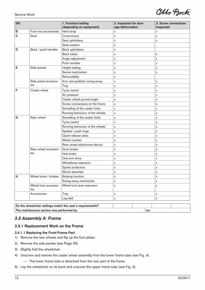
3.5.1.1 Replacing the Front Frame Part1) Remove the rear wheels and flip up the foot plates.2) Remove the side panels (see Page 33). 3) Slightly fold the wheelchair.4) Unscrew and remove the caster wheel assembly from the lower frame tube (see Fig. 4).
→ The lower frame tube is detached from the rear part of the frame.5) Lay the wheelchair on its back and unscrew the upper frame tube (see Fig. 5).
12 02/2011
Service Work
6) Remove the front part of the frame upward (see Fig. 6). 7) Remove all parts (knee lever brake, supports) installed on the frame.8) To reassemble, perform these steps in reverse order. Tighten the frame tubes with 23 Nm.
4 5
6
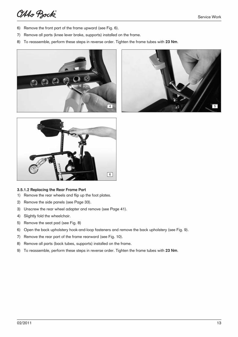
3.5.1.2 Replacing the Rear Frame Part1) Remove the rear wheels and flip up the foot plates.2) Remove the side panels (see Page 33). 3) Unscrew the rear wheel adapter and remove (see Page 41).4) Slightly fold the wheelchair.5) Remove the seat pad (see Fig. 8)6) Open the back upholstery hook-and-loop fasteners and remove the back upholstery (see Fig. 9).7) Remove the rear part of the frame rearward (see Fig. 10). 8) Remove all parts (back tubes, supports) installed on the frame.9) To reassemble, perform these steps in reverse order. Tighten the frame tubes with 23 Nm.
1302/2011
Service Work
7 8
9 10
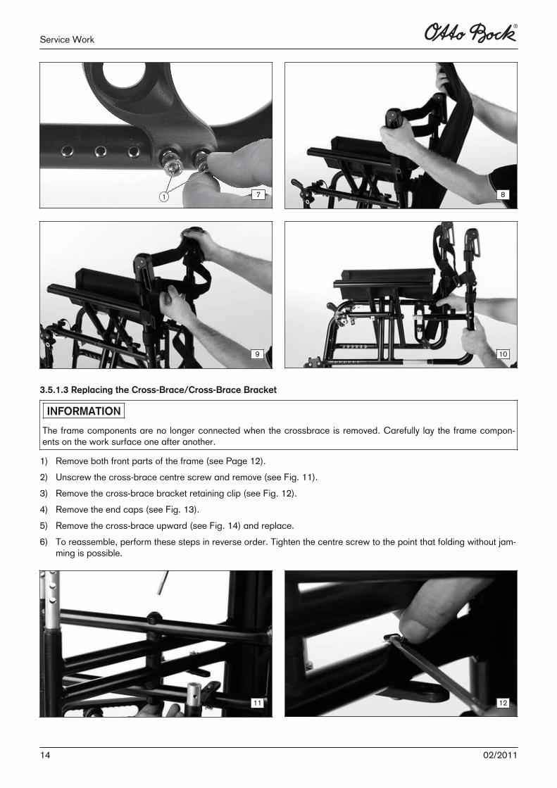
3.5.1.3 Replacing the Cross-Brace/Cross-Brace Bracket
INFORMATION
The frame components are no longer connected when the crossbrace is removed. Carefully lay the frame components on the work surface one after another.
1) Remove both front parts of the frame (see Page 12).2) Unscrew the cross-brace centre screw and remove (see Fig. 11).3) Remove the cross-brace bracket retaining clip (see Fig. 12).4) Remove the end caps (see Fig. 13).5) Remove the cross-brace upward (see Fig. 14) and replace.6) To reassemble, perform these steps in reverse order. Tighten the centre screw to the point that folding without jam
ming is possible.
11 12
14 02/2011
Service Work
13 14
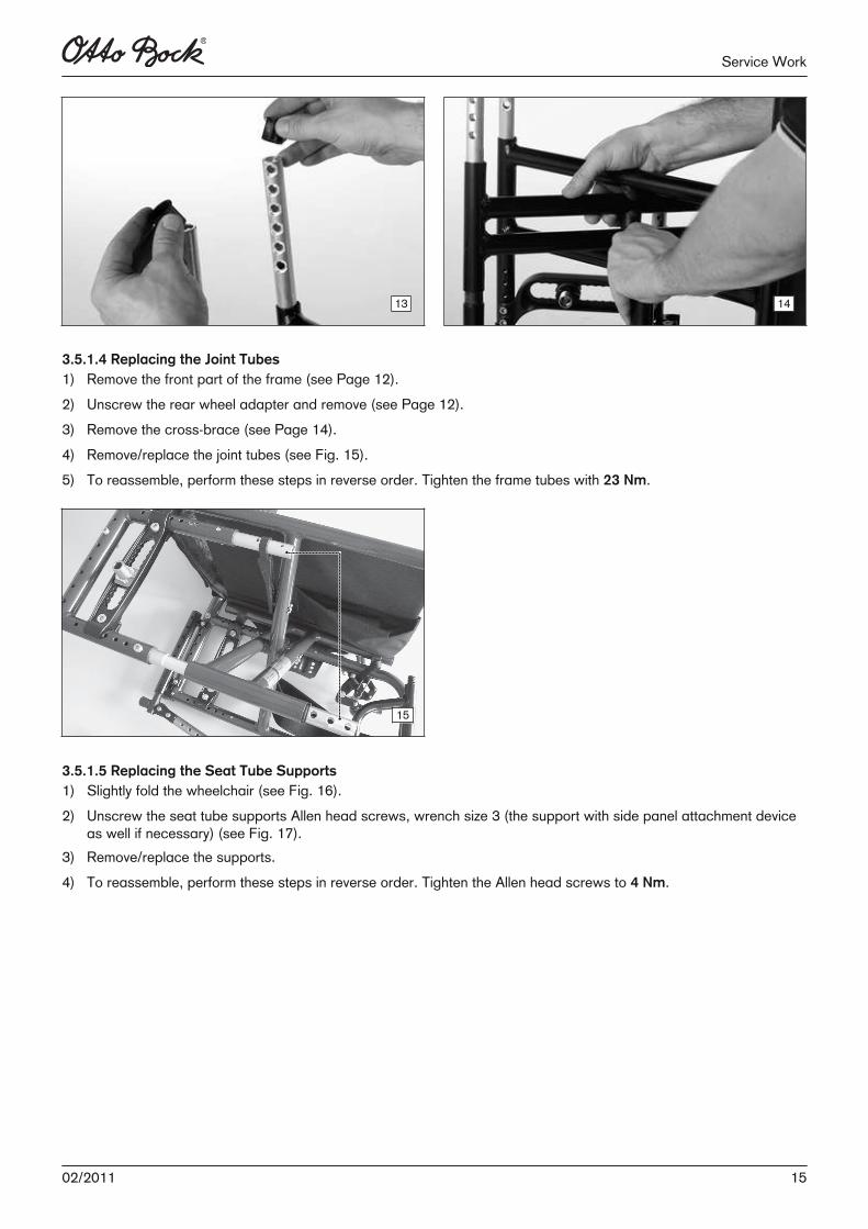
3.5.1.4 Replacing the Joint Tubes1) Remove the front part of the frame (see Page 12).2) Unscrew the rear wheel adapter and remove (see Page 12).3) Remove the cross-brace (see Page 14).4) Remove/replace the joint tubes (see Fig. 15).5) To reassemble, perform these steps in reverse order. Tighten the frame tubes with 23 Nm.
15
3.5.1.5 Replacing the Seat Tube Supports1) Slightly fold the wheelchair (see Fig. 16).2) Unscrew the seat tube supports Allen head screws, wrench size 3 (the support with side panel attachment device
as well if necessary) (see Fig. 17).3) Remove/replace the supports.4) To reassemble, perform these steps in reverse order. Tighten the Allen head screws to 4 Nm.
1502/2011
Service Work
16 17
3.5.2 Retrofitting the Vertical Accessory Mount
INFORMATION
The vertical accessory mount and the frame accessories cannot be installed on the welded Avantgarde CLT.
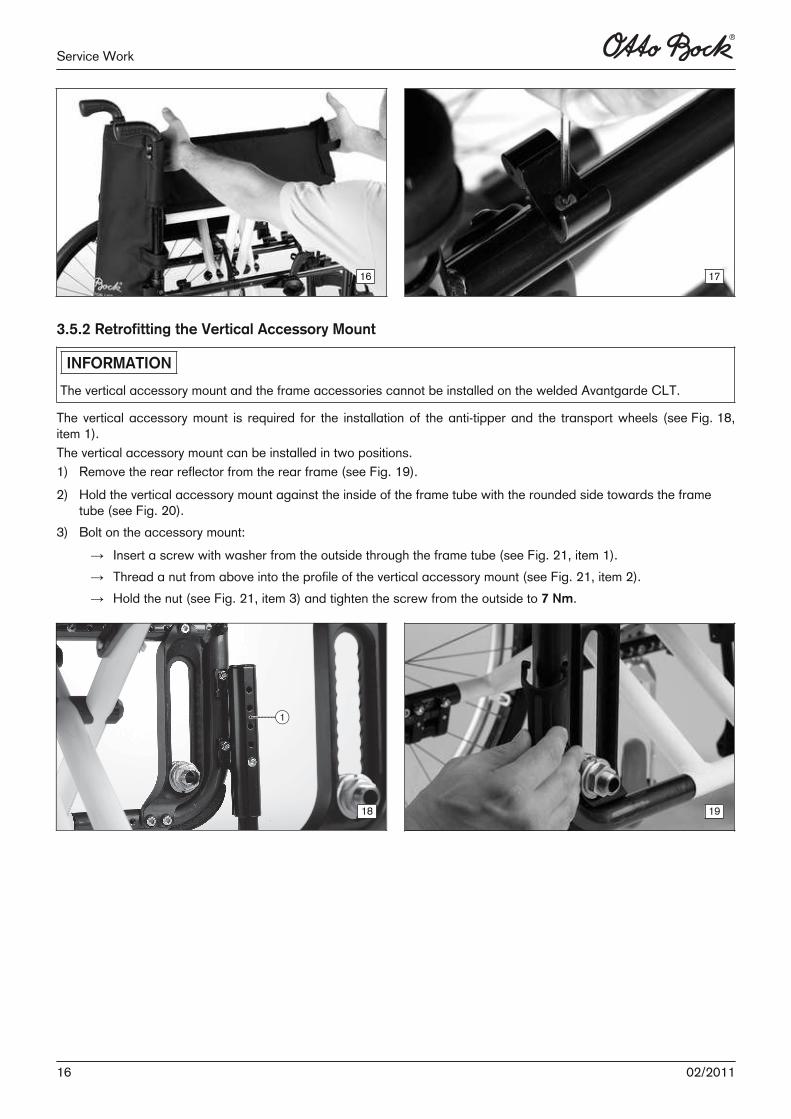
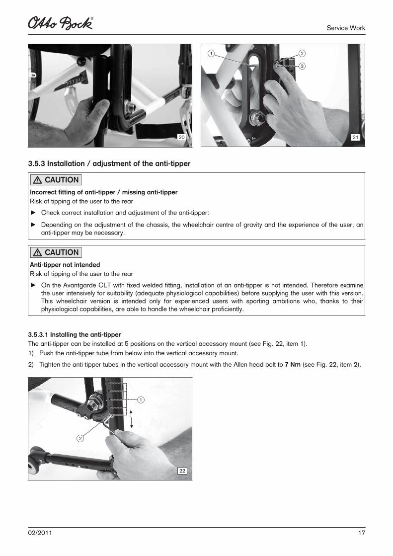
The vertical accessory mount is required for the installation of the anti-tipper and the transport wheels (see Fig. 18,item 1). The vertical accessory mount can be installed in two positions.1) Remove the rear reflector from the rear frame (see Fig. 19).2) Hold the vertical accessory mount against the inside of the frame tube with the rounded side towards the frame
tube (see Fig. 20).3) Bolt on the accessory mount:
→ Insert a screw with washer from the outside through the frame tube (see Fig. 21, item 1).→ Thread a nut from above into the profile of the vertical accessory mount (see Fig. 21, item 2).→ Hold the nut (see Fig. 21, item 3) and tighten the screw from the outside to 7 Nm.
18 19
16 02/2011
Service Work
20 21
3.5.3 Installation / adjustment of the anti-tipper
CAUTION
Incorrect fitting of anti-tipper / missing anti-tipperRisk of tipping of the user to the rear► Check correct installation and adjustment of the anti-tipper:
► Depending on the adjustment of the chassis, the wheelchair centre of gravity and the experience of the user, ananti-tipper may be necessary.
CAUTION
Anti-tipper not intendedRisk of tipping of the user to the rear► On the Avantgarde CLT with fixed welded fitting, installation of an anti-tipper is not intended. Therefore examine
the user intensively for suitability (adequate physiological capabilities) before supplying the user with this version.This wheelchair version is intended only for experienced users with sporting ambitions who, thanks to theirphysiological capabilities, are able to handle the wheelchair proficiently.
3.5.3.1 Installing the anti-tipperThe anti-tipper can be installed at 5 positions on the vertical accessory mount (see Fig. 22, item 1).1) Push the anti-tipper tube from below into the vertical accessory mount.2) Tighten the anti-tipper tubes in the vertical accessory mount with the Allen head bolt to 7 Nm (see Fig. 22, item 2).
22
1702/2011
Service Work
3.5.3.2 Adjustment of the anti-tipper
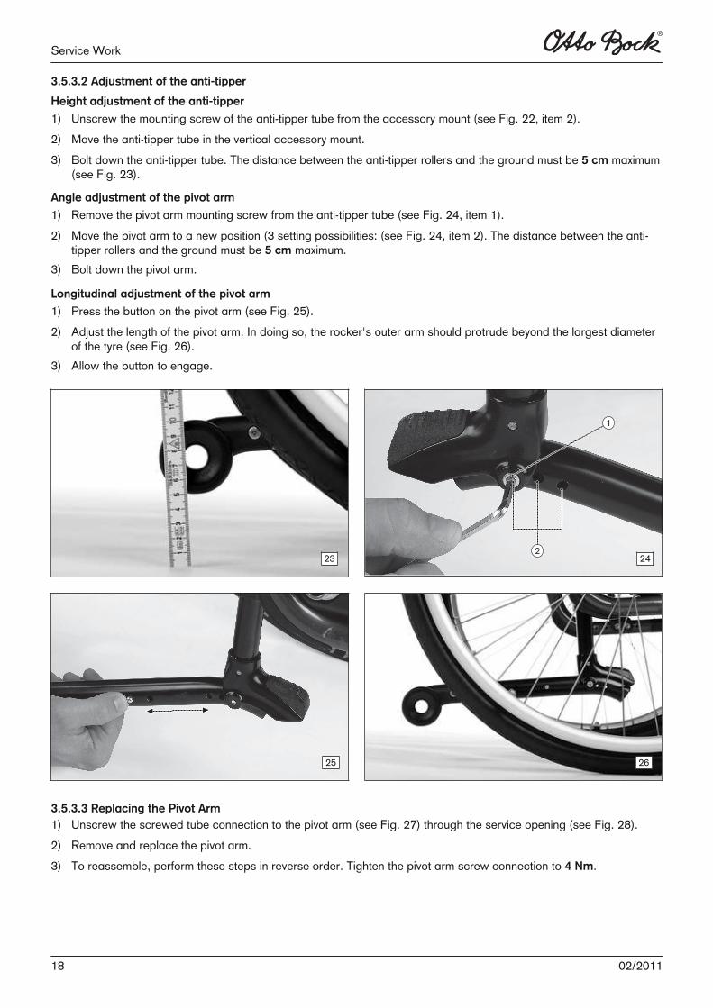
Height adjustment of the anti-tipper
1) Unscrew the mounting screw of the anti-tipper tube from the accessory mount (see Fig. 22, item 2).2) Move the anti-tipper tube in the vertical accessory mount.3) Bolt down the anti-tipper tube. The distance between the anti-tipper rollers and the ground must be 5 cm maximum
(see Fig. 23).
Angle adjustment of the pivot arm
1) Remove the pivot arm mounting screw from the anti-tipper tube (see Fig. 24, item 1).2) Move the pivot arm to a new position (3 setting possibilities: (see Fig. 24, item 2). The distance between the anti-
tipper rollers and the ground must be 5 cm maximum.3) Bolt down the pivot arm.
Longitudinal adjustment of the pivot arm
1) Press the button on the pivot arm (see Fig. 25).2) Adjust the length of the pivot arm. In doing so, the rocker's outer arm should protrude beyond the largest diameter
of the tyre (see Fig. 26).3) Allow the button to engage.
23 24
25 26
3.5.3.3 Replacing the Pivot Arm1) Unscrew the screwed tube connection to the pivot arm (see Fig. 27) through the service opening (see Fig. 28).2) Remove and replace the pivot arm.3) To reassemble, perform these steps in reverse order. Tighten the pivot arm screw connection to 4 Nm.
18 02/2011
Service Work
27 28
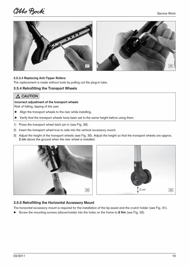
3.5.3.4 Replacing Anti-Tipper RollersThe replacement is made without tools by pulling out the plug-in tube.
3.5.4 Retrofitting the Transport Wheels
CAUTION
Incorrect adjustment of the transport wheelsRisk of falling, tipping of the user► Align the transport wheels to the rear while installing.
► Verify that the transport wheels have been set to the same height before using them.
1) Press the transport wheel latch pin in (see Fig. 29).2) Insert the transport wheel true to side into the vertical accessory mount.3) Adjust the height of the transport wheels (see Fig. 30). Adjust the height so that the transport wheels are approx.
2 cm above the ground when the rear wheel is installed.
29 2 cm 30
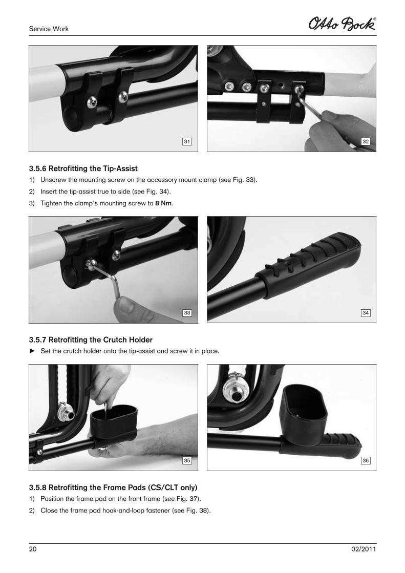
3.5.5 Retrofitting the Horizontal Accessory MountThe horizontal accessory mount is required for the installation of the tip-assist and the crutch holder (see Fig. 31).► Screw the mounting screws (above/inside) into the holes on the frame to 8 Nm (see Fig. 32).
1902/2011
Service Work
31 32
3.5.6 Retrofitting the Tip-Assist1) Unscrew the mounting screw on the accessory mount clamp (see Fig. 33).2) Insert the tip-assist true to side (see Fig. 34).3) Tighten the clamp's mounting screw to 8 Nm.
33 34
3.5.7 Retrofitting the Crutch Holder► Set the crutch holder onto the tip-assist and screw it in place.
35 36
3.5.8 Retrofitting the Frame Pads (CS/CLT only)1) Position the frame pad on the front frame (see Fig. 37).2) Close the frame pad hook-and-loop fastener (see Fig. 38).
20 02/2011
Service Work
37 38
3.6 Assembly B: Footrest
3.6.1 Adjusting the Foot Rests/Tube Foot Rest/Foot PlatesAll instructions concerning the adjustment of the foot rests are included in the Instructions for Use (qualified personnel)– order number 647G585.
3.6.2 Replacement Work on the CV Model
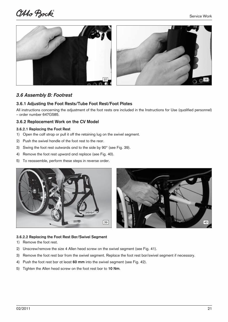
3.6.2.1 Replacing the Foot Rest1) Open the calf strap or pull it off the retaining lug on the swivel segment.2) Push the swivel handle of the foot rest to the rear.3) Swing the foot rest outwards and to the side by 90° (see Fig. 39). 4) Remove the foot rest upward and replace (see Fig. 40).5) To reassemble, perform these steps in reverse order.
39 40
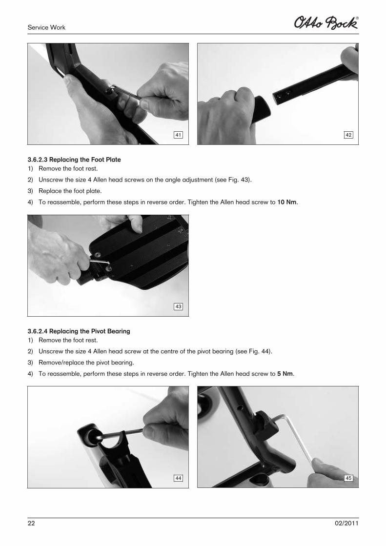
3.6.2.2 Replacing the Foot Rest Bar/Swivel Segment1) Remove the foot rest.2) Unscrew/remove the size 4 Allen head screw on the swivel segment (see Fig. 41).3) Remove the foot rest bar from the swivel segment. Replace the foot rest bar/swivel segment if necessary.4) Push the foot rest bar at least 60 mm into the swivel segment (see Fig. 42).5) Tighten the Allen head screw on the foot rest bar to 10 Nm.
2102/2011
Service Work
41 42
3.6.2.3 Replacing the Foot Plate1) Remove the foot rest.2) Unscrew the size 4 Allen head screws on the angle adjustment (see Fig. 43).3) Replace the foot plate.4) To reassemble, perform these steps in reverse order. Tighten the Allen head screw to 10 Nm.
43
3.6.2.4 Replacing the Pivot Bearing1) Remove the foot rest.2) Unscrew the size 4 Allen head screw at the centre of the pivot bearing (see Fig. 44).3) Remove/replace the pivot bearing.4) To reassemble, perform these steps in reverse order. Tighten the Allen head screw to 5 Nm.
44 45
22 02/2011
Service Work
3.6.2.5 Replacing the Locking Device1) Remove the foot rest.2) Unscrew the size 4 Allen head screw on the locking device (see Fig. 45).3) Remove/replace the locking device.4) To reassemble, perform these steps in reverse order. Tighten the Allen head screw to 5 Nm.
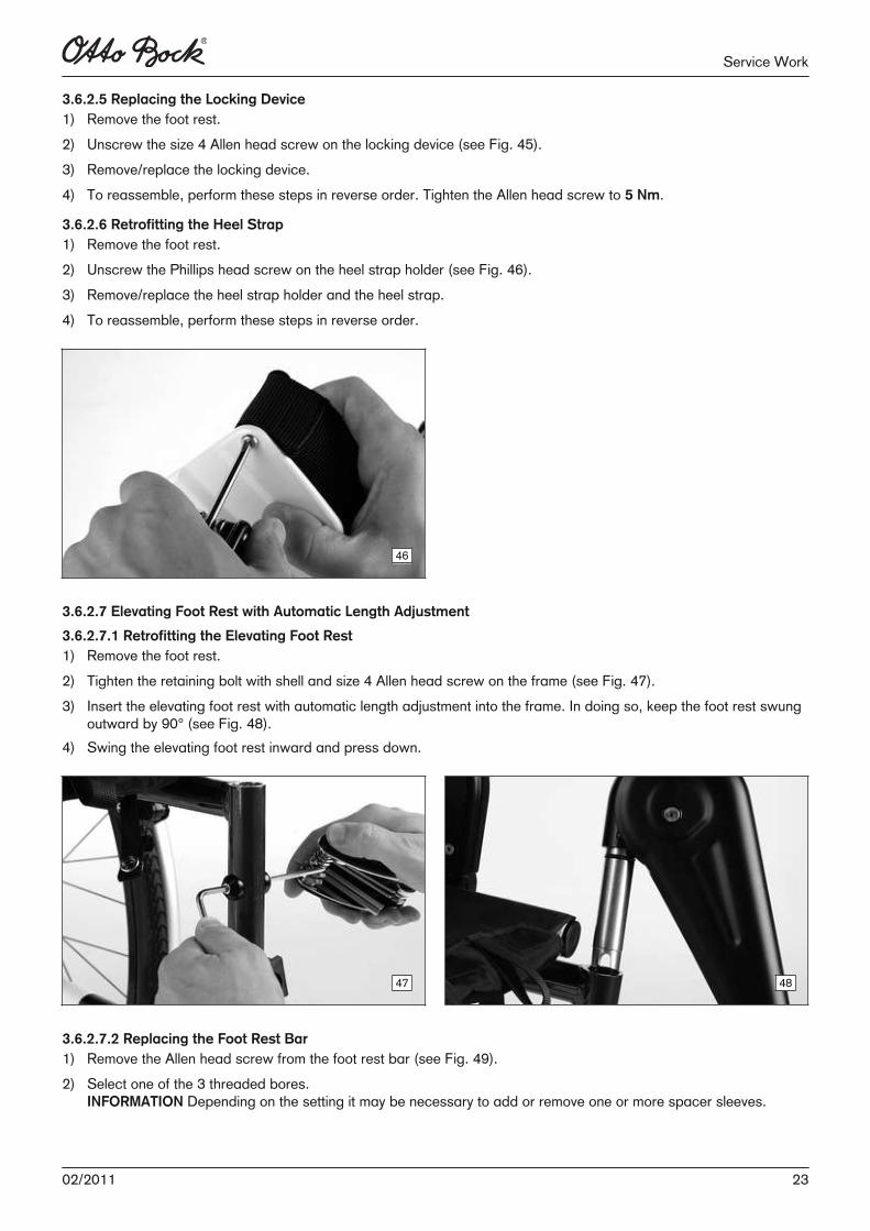
3.6.2.6 Retrofitting the Heel Strap1) Remove the foot rest.2) Unscrew the Phillips head screw on the heel strap holder (see Fig. 46).3) Remove/replace the heel strap holder and the heel strap.4) To reassemble, perform these steps in reverse order.
46
3.6.2.7 Elevating Foot Rest with Automatic Length Adjustment
3.6.2.7.1 Retrofitting the Elevating Foot Rest1) Remove the foot rest.2) Tighten the retaining bolt with shell and size 4 Allen head screw on the frame (see Fig. 47).3) Insert the elevating foot rest with automatic length adjustment into the frame. In doing so, keep the foot rest swung
outward by 90° (see Fig. 48).4) Swing the elevating foot rest inward and press down.
47 48
3.6.2.7.2 Replacing the Foot Rest Bar1) Remove the Allen head screw from the foot rest bar (see Fig. 49).2) Select one of the 3 threaded bores.
INFORMATION Depending on the setting it may be necessary to add or remove one or more spacer sleeves.
2302/2011
Service Work
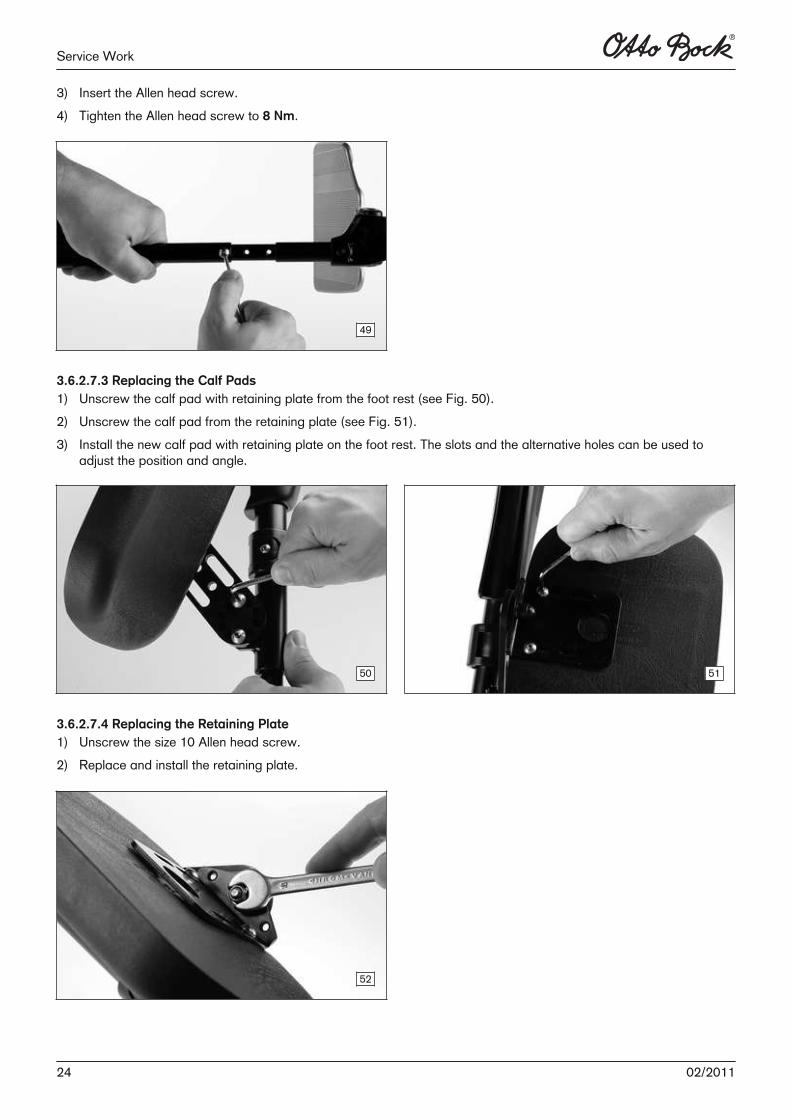
3) Insert the Allen head screw. 4) Tighten the Allen head screw to 8 Nm.
49
3.6.2.7.3 Replacing the Calf Pads1) Unscrew the calf pad with retaining plate from the foot rest (see Fig. 50).2) Unscrew the calf pad from the retaining plate (see Fig. 51).3) Install the new calf pad with retaining plate on the foot rest. The slots and the alternative holes can be used to
adjust the position and angle.
50 51
3.6.2.7.4 Replacing the Retaining Plate1) Unscrew the size 10 Allen head screw.2) Replace and install the retaining plate.
52
24 02/2011
Service Work
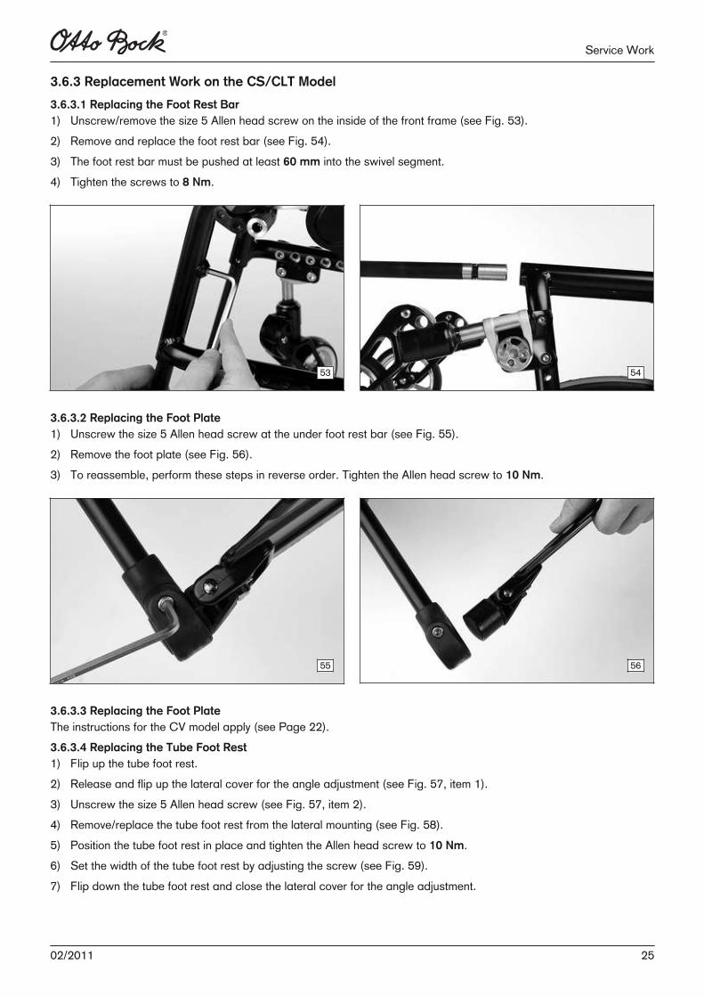
3.6.3 Replacement Work on the CS/CLT Model
3.6.3.1 Replacing the Foot Rest Bar1) Unscrew/remove the size 5 Allen head screw on the inside of the front frame (see Fig. 53).2) Remove and replace the foot rest bar (see Fig. 54).3) The foot rest bar must be pushed at least 60 mm into the swivel segment.4) Tighten the screws to 8 Nm.
53 54
3.6.3.2 Replacing the Foot Plate1) Unscrew the size 5 Allen head screw at the under foot rest bar (see Fig. 55).2) Remove the foot plate (see Fig. 56).3) To reassemble, perform these steps in reverse order. Tighten the Allen head screw to 10 Nm.
55 56
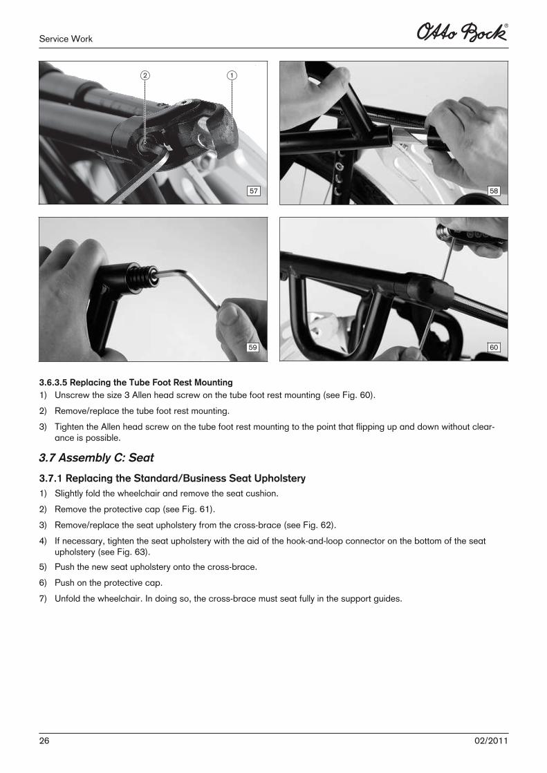
3.6.3.3 Replacing the Foot PlateThe instructions for the CV model apply (see Page 22).3.6.3.4 Replacing the Tube Foot Rest1) Flip up the tube foot rest.2) Release and flip up the lateral cover for the angle adjustment (see Fig. 57, item 1).3) Unscrew the size 5 Allen head screw (see Fig. 57, item 2).4) Remove/replace the tube foot rest from the lateral mounting (see Fig. 58).5) Position the tube foot rest in place and tighten the Allen head screw to 10 Nm.6) Set the width of the tube foot rest by adjusting the screw (see Fig. 59). 7) Flip down the tube foot rest and close the lateral cover for the angle adjustment.
2502/2011
Service Work
57 58
59 60
3.6.3.5 Replacing the Tube Foot Rest Mounting1) Unscrew the size 3 Allen head screw on the tube foot rest mounting (see Fig. 60).2) Remove/replace the tube foot rest mounting.3) Tighten the Allen head screw on the tube foot rest mounting to the point that flipping up and down without clear
ance is possible.
3.7 Assembly C: Seat
3.7.1 Replacing the Standard/Business Seat Upholstery1) Slightly fold the wheelchair and remove the seat cushion.2) Remove the protective cap (see Fig. 61).3) Remove/replace the seat upholstery from the cross-brace (see Fig. 62).4) If necessary, tighten the seat upholstery with the aid of the hook-and-loop connector on the bottom of the seat
upholstery (see Fig. 63).5) Push the new seat upholstery onto the cross-brace.6) Push on the protective cap.7) Unfold the wheelchair. In doing so, the cross-brace must seat fully in the support guides.
26 02/2011
Service Work
61 62
63
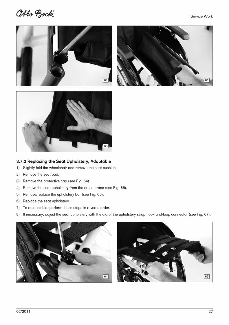
3.7.2 Replacing the Seat Upholstery, Adaptable1) Slightly fold the wheelchair and remove the seat cushion.2) Remove the seat pad.3) Remove the protective cap (see Fig. 64).4) Remove the seat upholstery from the cross-brace (see Fig. 65).5) Remove/replace the upholstery bar (see Fig. 66).6) Replace the seat upholstery.7) To reassemble, perform these steps in reverse order.8) If necessary, adjust the seat upholstery with the aid of the upholstery strap hook-and-loop connector (see Fig. 67).
64 65
2702/2011
Service Work
66 67
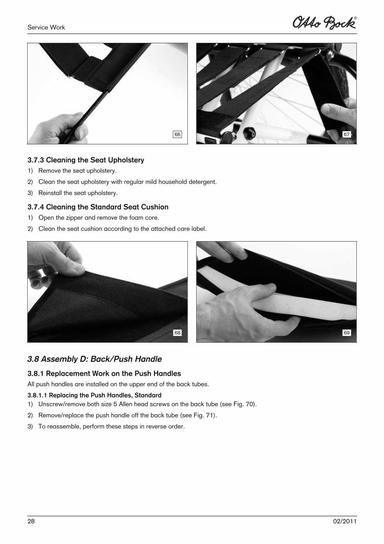
3.7.3 Cleaning the Seat Upholstery1) Remove the seat upholstery.2) Clean the seat upholstery with regular mild household detergent.3) Reinstall the seat upholstery.
3.7.4 Cleaning the Standard Seat Cushion1) Open the zipper and remove the foam core.2) Clean the seat cushion according to the attached care label.
68 69
3.8 Assembly D: Back/Push Handle
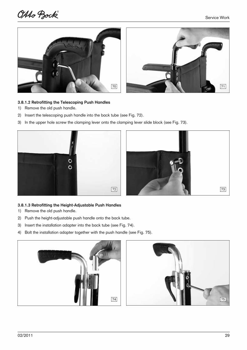
3.8.1 Replacement Work on the Push HandlesAll push handles are installed on the upper end of the back tubes.3.8.1.1 Replacing the Push Handles, Standard1) Unscrew/remove both size 5 Allen head screws on the back tube (see Fig. 70).2) Remove/replace the push handle off the back tube (see Fig. 71).3) To reassemble, perform these steps in reverse order.
28 02/2011
Service Work
70 71
3.8.1.2 Retrofitting the Telescoping Push Handles1) Remove the old push handle.2) Insert the telescoping push handle into the back tube (see Fig. 72).3) In the upper hole screw the clamping lever onto the clamping lever slide block (see Fig. 73).
72 73
3.8.1.3 Retrofitting the Height-Adjustable Push Handles1) Remove the old push handle.2) Push the height-adjustable push handle onto the back tube.3) Insert the installation adapter into the back tube (see Fig. 74).4) Bolt the installation adapter together with the push handle (see Fig. 75).
74 75
2902/2011
Service Work
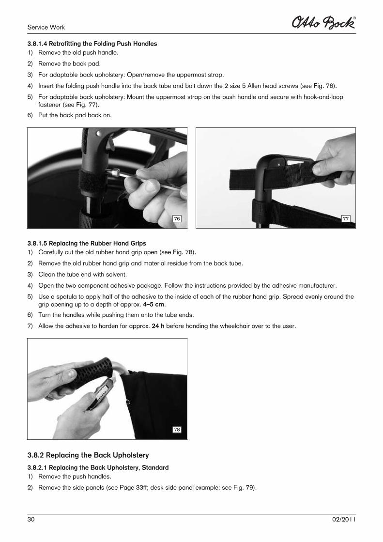
3.8.1.4 Retrofitting the Folding Push Handles1) Remove the old push handle.2) Remove the back pad.3) For adaptable back upholstery: Open/remove the uppermost strap.4) Insert the folding push handle into the back tube and bolt down the 2 size 5 Allen head screws (see Fig. 76).5) For adaptable back upholstery: Mount the uppermost strap on the push handle and secure with hook-and-loop
fastener (see Fig. 77).6) Put the back pad back on.
76 77
3.8.1.5 Replacing the Rubber Hand Grips1) Carefully cut the old rubber hand grip open (see Fig. 78).2) Remove the old rubber hand grip and material residue from the back tube.3) Clean the tube end with solvent.4) Open the two-component adhesive package. Follow the instructions provided by the adhesive manufacturer.5) Use a spatula to apply half of the adhesive to the inside of each of the rubber hand grip. Spread evenly around the
grip opening up to a depth of approx. 4–5 cm.6) Turn the handles while pushing them onto the tube ends.7) Allow the adhesive to harden for approx. 24 h before handing the wheelchair over to the user.
78
3.8.2 Replacing the Back Upholstery
3.8.2.1 Replacing the Back Upholstery, Standard1) Remove the push handles.2) Remove the side panels (see Page 33ff; desk side panel example: see Fig. 79).
30 02/2011
Service Work
3) Remove/replace the back upholstery (see Fig. 80). 4) To reassemble, perform these steps in reverse order.
79 80
3.8.2.2 Replacing the Back Upholstery, Adaptable1) Remove the push handles.2) Remove the side panels.3) Remove the back pad.4) Open the uppermost strap and remove/replace (see Fig. 81). 5) Remove/replace other straps (see Fig. 82).6) To reassemble, perform these steps in reverse order.
81 82
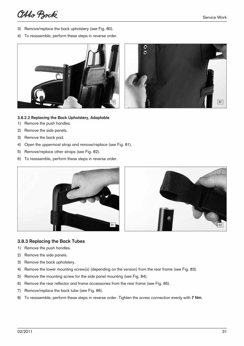
3.8.3 Replacing the Back Tubes1) Remove the push handles.2) Remove the side panels.3) Remove the back upholstery.4) Remove the lower mounting screw(s) (depending on the version) from the rear frame (see Fig. 83).5) Remove the mounting screw for the side panel mounting (see Fig. 84).6) Remove the rear reflector and frame accessories from the rear frame (see Fig. 85).7) Remove/replace the back tube (see Fig. 86).8) To reassemble, perform these steps in reverse order. Tighten the screw connection evenly with 7 Nm.
3102/2011
Service Work
83 84
85 86
3.8.4 Replacing the Angle-Adjustable Back Tubes
CAUTION
Missing anti-tipperRisk of tipping of the user to the rear► When using the 30° backrest angle with short wheelbase, two anti-tippers (one on each side) and with long
wheelbase at least one anti-tipper must be fitted and activated.
► Check that the anti-tipper is securely attached.
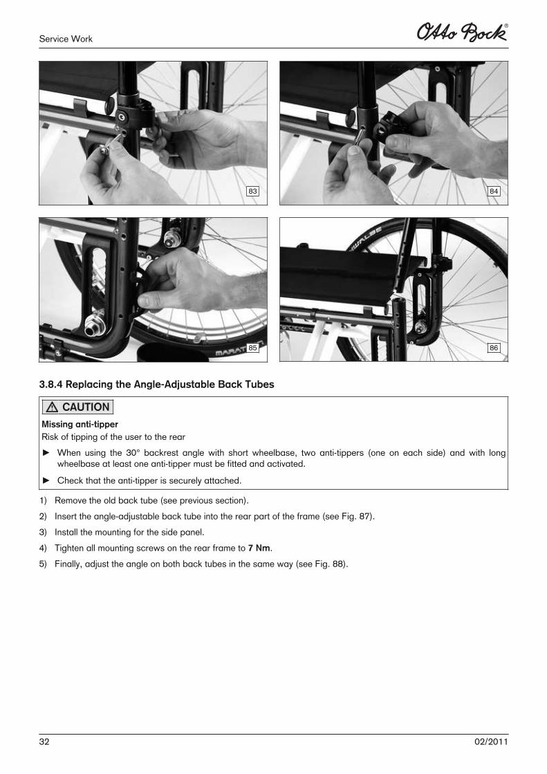
1) Remove the old back tube (see previous section).2) Insert the angle-adjustable back tube into the rear part of the frame (see Fig. 87).3) Install the mounting for the side panel.4) Tighten all mounting screws on the rear frame to 7 Nm.5) Finally, adjust the angle on both back tubes in the same way (see Fig. 88).
32 02/2011
Service Work
87 88
3.9 Assembly E: Side Panels
3.9.1 Replacement Work on the Standard Side Panel/Clothing Protector
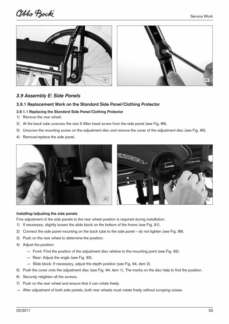
3.9.1.1 Replacing the Standard Side Panel/Clothing Protector1) Remove the rear wheel.2) At the back tube unscrew the size 5 Allen head screw from the side panel (see Fig. 89).3) Unscrew the mounting screw on the adjustment disc and remove the cover of the adjustment disc (see Fig. 90).4) Remove/replace the side panel.
89 90
Installing/adjusting the side panels
Fine adjustment of the side panels to the rear wheel position is required during installation:1) If necessary, slightly loosen the slide block on the bottom of the frame (see Fig. 91).2) Connect the side panel mounting on the back tube to the side panel – do not tighten (see Fig. 89).3) Push on the rear wheel to determine the position.4) Adjust the position:
→ Front: Find the position of the adjustment disc relative to the mounting point (see Fig. 92).→ Rear: Adjust the angle (see Fig. 93).→ Slide block: If necessary, adjust the depth position (see Fig. 94, item 2).
5) Push the cover onto the adjustment disc (see Fig. 94, item 1). The marks on the disc help to find the position.6) Securely retighten all the screws.7) Push on the rear wheel and ensure that it can rotate freely.→ After adjustment of both side panels, both rear wheels must rotate freely without scraping noises.
3302/2011
Service Work
91 92
93 94
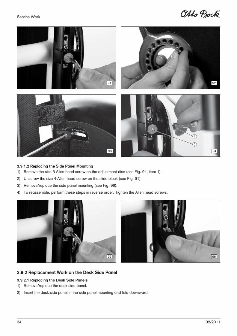
3.9.1.2 Replacing the Side Panel Mounting1) Remove the size 5 Allen head screw on the adjustment disc (see Fig. 94, item 1).2) Unscrew the size 4 Allen head screw on the slide block (see Fig. 91).3) Remove/replace the side panel mounting (see Fig. 96).4) To reassemble, perform these steps in reverse order. Tighten the Allen head screws.
95 96
3.9.2 Replacement Work on the Desk Side Panel
3.9.2.1 Replacing the Desk Side Panels1) Remove/replace the desk side panel.2) Insert the desk side panel in the side panel mounting and fold downward.
34 02/2011
Service Work
97 98
3.9.2.2 Replacing the Side Panel Mounting1) Remove the desk side panel (see Fig. 99).2) Unscrew the size 3 Allen head screw (see Fig. 100).3) Remove/replace the side panel mounting.4) To reassemble, perform these steps in reverse order. Tighten the Allen head screw to 5 Nm.
99 100
3.9.2.3 Replacing the Seat Tube SupportFor the replacement see Page 15.3.9.2.4 Replacing the Retaining Clip1) Remove the desk side panel.2) Unscrew the size 5 Allen head screw on the retaining clip (see Fig. 101).3) Replace/position/bolt down the retaining clip.
101 102
3502/2011
Service Work
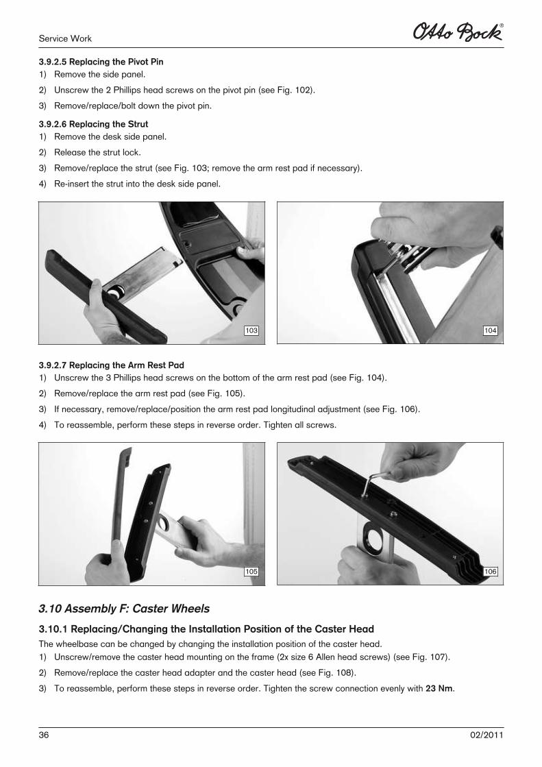
3.9.2.5 Replacing the Pivot Pin1) Remove the side panel.2) Unscrew the 2 Phillips head screws on the pivot pin (see Fig. 102).3) Remove/replace/bolt down the pivot pin.
3.9.2.6 Replacing the Strut1) Remove the desk side panel.2) Release the strut lock.3) Remove/replace the strut (see Fig. 103; remove the arm rest pad if necessary).4) Re-insert the strut into the desk side panel.
103 104
3.9.2.7 Replacing the Arm Rest Pad1) Unscrew the 3 Phillips head screws on the bottom of the arm rest pad (see Fig. 104).2) Remove/replace the arm rest pad (see Fig. 105).3) If necessary, remove/replace/position the arm rest pad longitudinal adjustment (see Fig. 106).4) To reassemble, perform these steps in reverse order. Tighten all screws.
105 106
3.10 Assembly F: Caster Wheels
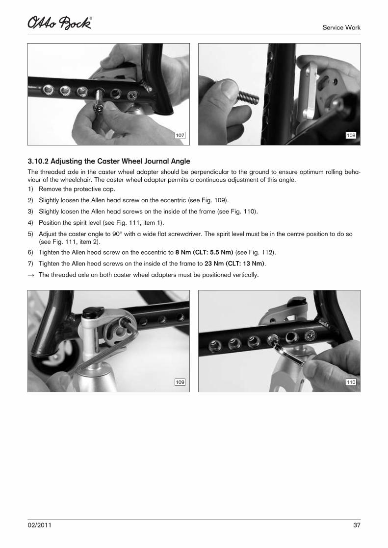
3.10.1 Replacing/Changing the Installation Position of the Caster HeadThe wheelbase can be changed by changing the installation position of the caster head.1) Unscrew/remove the caster head mounting on the frame (2x size 6 Allen head screws) (see Fig. 107).2) Remove/replace the caster head adapter and the caster head (see Fig. 108).3) To reassemble, perform these steps in reverse order. Tighten the screw connection evenly with 23 Nm.
36 02/2011
Service Work
107 108
3.10.2 Adjusting the Caster Wheel Journal AngleThe threaded axle in the caster wheel adapter should be perpendicular to the ground to ensure optimum rolling behaviour of the wheelchair. The caster wheel adapter permits a continuous adjustment of this angle.1) Remove the protective cap.2) Slightly loosen the Allen head screw on the eccentric (see Fig. 109).3) Slightly loosen the Allen head screws on the inside of the frame (see Fig. 110).4) Position the spirit level (see Fig. 111, item 1).5) Adjust the caster angle to 90° with a wide flat screwdriver. The spirit level must be in the centre position to do so
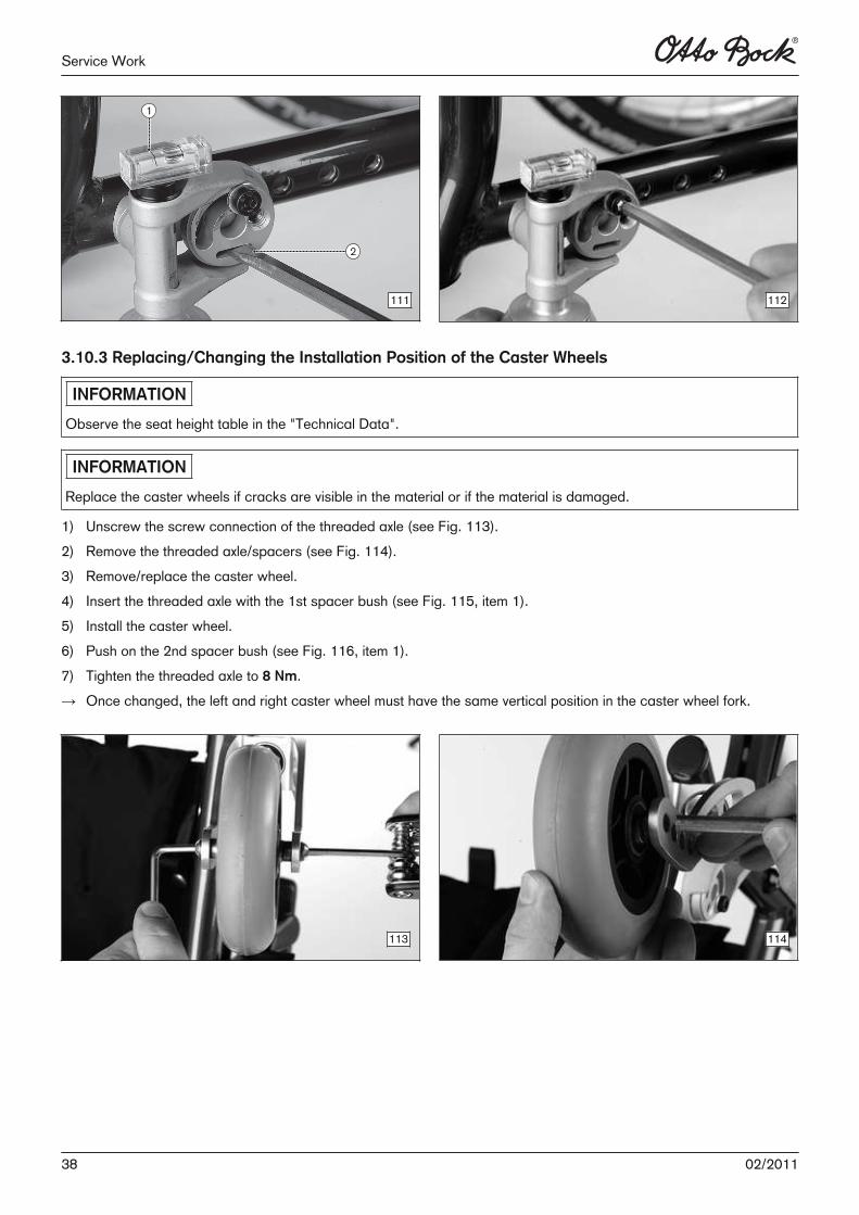
(see Fig. 111, item 2).6) Tighten the Allen head screw on the eccentric to 8 Nm (CLT: 5.5 Nm) (see Fig. 112).7) Tighten the Allen head screws on the inside of the frame to 23 Nm (CLT: 13 Nm).→ The threaded axle on both caster wheel adapters must be positioned vertically.
109 110
3702/2011
Service Work
111 112
3.10.3 Replacing/Changing the Installation Position of the Caster Wheels
INFORMATION
Observe the seat height table in the "Technical Data".
INFORMATION
Replace the caster wheels if cracks are visible in the material or if the material is damaged.
1) Unscrew the screw connection of the threaded axle (see Fig. 113). 2) Remove the threaded axle/spacers (see Fig. 114).3) Remove/replace the caster wheel.4) Insert the threaded axle with the 1st spacer bush (see Fig. 115, item 1).5) Install the caster wheel.6) Push on the 2nd spacer bush (see Fig. 116, item 1).7) Tighten the threaded axle to 8 Nm.→ Once changed, the left and right caster wheel must have the same vertical position in the caster wheel fork.
113 114
38 02/2011
Service Work
115 116
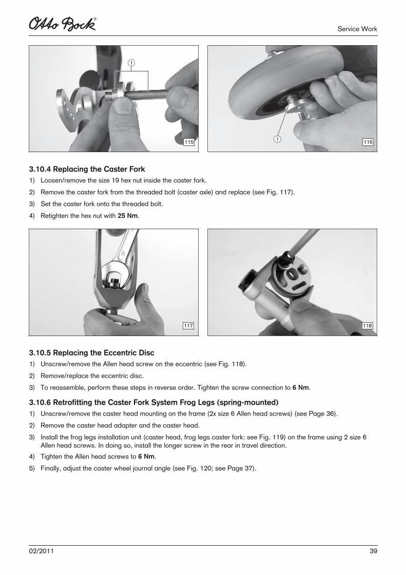
3.10.4 Replacing the Caster Fork1) Loosen/remove the size 19 hex nut inside the caster fork.2) Remove the caster fork from the threaded bolt (caster axle) and replace (see Fig. 117). 3) Set the caster fork onto the threaded bolt.4) Retighten the hex nut with 25 Nm.
117 118
3.10.5 Replacing the Eccentric Disc1) Unscrew/remove the Allen head screw on the eccentric (see Fig. 118).2) Remove/replace the eccentric disc.3) To reassemble, perform these steps in reverse order. Tighten the screw connection to 6 Nm.
3.10.6 Retrofitting the Caster Fork System Frog Legs (spring-mounted)1) Unscrew/remove the caster head mounting on the frame (2x size 6 Allen head screws) (see Page 36).2) Remove the caster head adapter and the caster head.3) Install the frog legs installation unit (caster head, frog legs caster fork: see Fig. 119) on the frame using 2 size 6
Allen head screws. In doing so, install the longer screw in the rear in travel direction. 4) Tighten the Allen head screws to 6 Nm.5) Finally, adjust the caster wheel journal angle (see Fig. 120; see Page 37).
3902/2011
Service Work
119 120
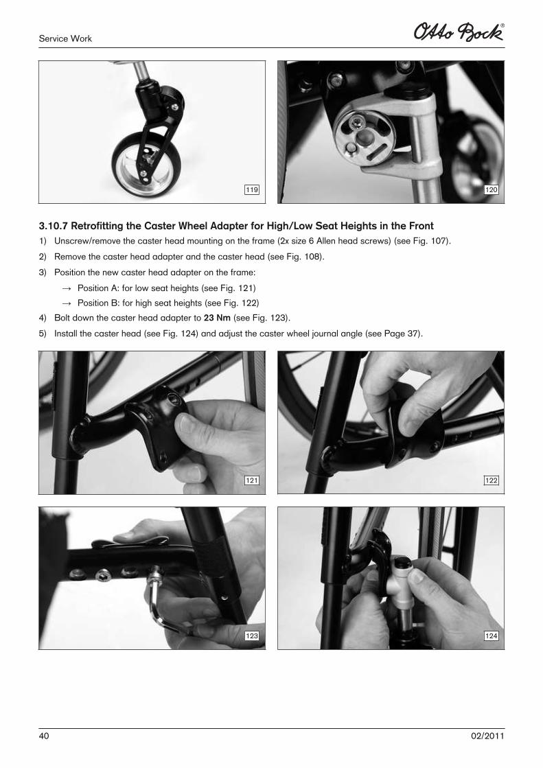
3.10.7 Retrofitting the Caster Wheel Adapter for High/Low Seat Heights in the Front1) Unscrew/remove the caster head mounting on the frame (2x size 6 Allen head screws) (see Fig. 107).2) Remove the caster head adapter and the caster head (see Fig. 108).3) Position the new caster head adapter on the frame:
→ Position A: for low seat heights (see Fig. 121)→ Position B: for high seat heights (see Fig. 122)
4) Bolt down the caster head adapter to 23 Nm (see Fig. 123). 5) Install the caster head (see Fig. 124) and adjust the caster wheel journal angle (see Page 37).
121 122
123 124
40 02/2011
Service Work
3.11 Assembly G: Rear Wheels
3.11.1 Adjusting the Rear Wheels/Rear Wheel Adapters
INFORMATION
If the rear wheel size is changed, then the knee lever wheel lock must be readjusted as well (see section "Adjustingthe wheel lock").
INFORMATION
Changing the rear wheel position also changes the angle between the caster axles and the ground. Alsoreplace/change the installation position of the caster wheels if necessary (see section "Replacing and changing theinstallation position of the caster wheels").
All instructions concerning the adjustment of the rear wheels/real wheel adapters are included in the Instructions forUse (qualified personnel) – order number 647G585.
3.11.2 Rear Wheel Adapter, Standard
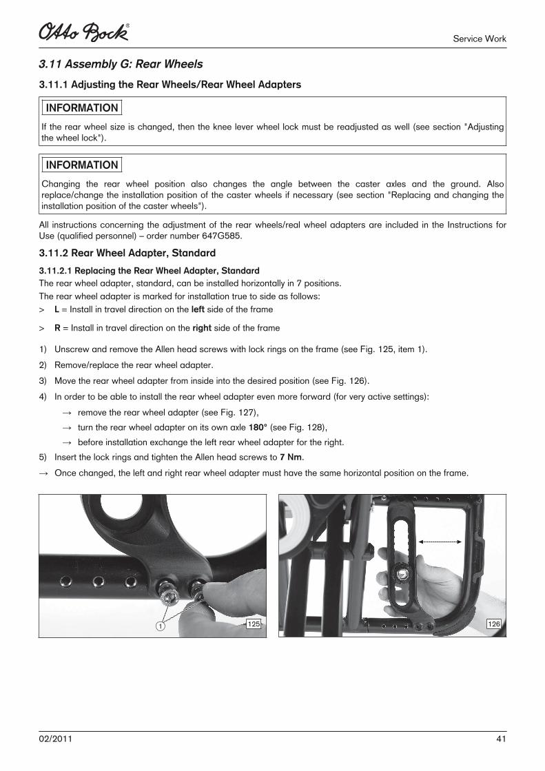
3.11.2.1 Replacing the Rear Wheel Adapter, StandardThe rear wheel adapter, standard, can be installed horizontally in 7 positions.The rear wheel adapter is marked for installation true to side as follows:> L = Install in travel direction on the left side of the frame
> R = Install in travel direction on the right side of the frame
1) Unscrew and remove the Allen head screws with lock rings on the frame (see Fig. 125, item 1). 2) Remove/replace the rear wheel adapter.3) Move the rear wheel adapter from inside into the desired position (see Fig. 126). 4) In order to be able to install the rear wheel adapter even more forward (for very active settings):
→ remove the rear wheel adapter (see Fig. 127),→ turn the rear wheel adapter on its own axle 180° (see Fig. 128),→ before installation exchange the left rear wheel adapter for the right.
5) Insert the lock rings and tighten the Allen head screws to 7 Nm.→ Once changed, the left and right rear wheel adapter must have the same horizontal position on the frame.
125 126
4102/2011
Service Work
127 128
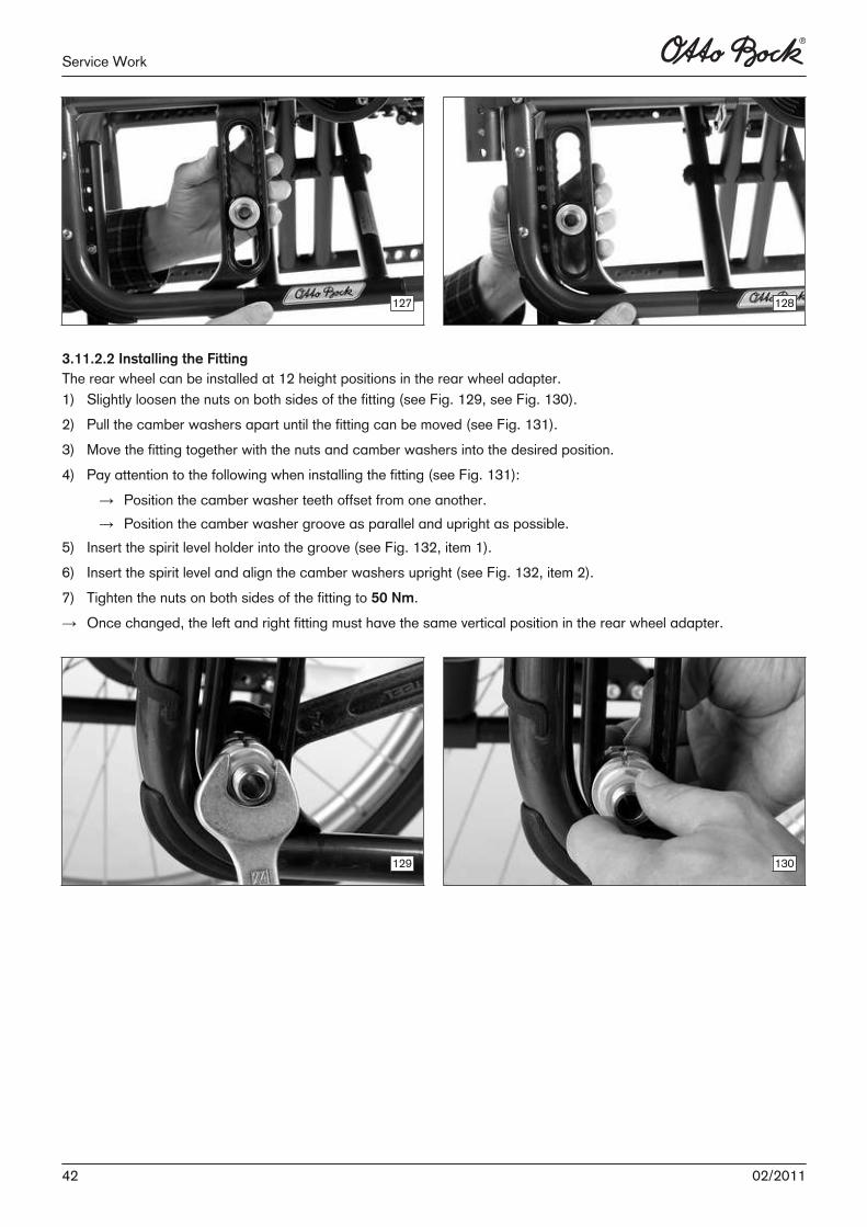
3.11.2.2 Installing the FittingThe rear wheel can be installed at 12 height positions in the rear wheel adapter.1) Slightly loosen the nuts on both sides of the fitting (see Fig. 129, see Fig. 130).2) Pull the camber washers apart until the fitting can be moved (see Fig. 131).3) Move the fitting together with the nuts and camber washers into the desired position.4) Pay attention to the following when installing the fitting (see Fig. 131):
→ Position the camber washer teeth offset from one another.→ Position the camber washer groove as parallel and upright as possible.
5) Insert the spirit level holder into the groove (see Fig. 132, item 1).6) Insert the spirit level and align the camber washers upright (see Fig. 132, item 2).7) Tighten the nuts on both sides of the fitting to 50 Nm.→ Once changed, the left and right fitting must have the same vertical position in the rear wheel adapter.
129 130
42 02/2011
Service Work
131 132
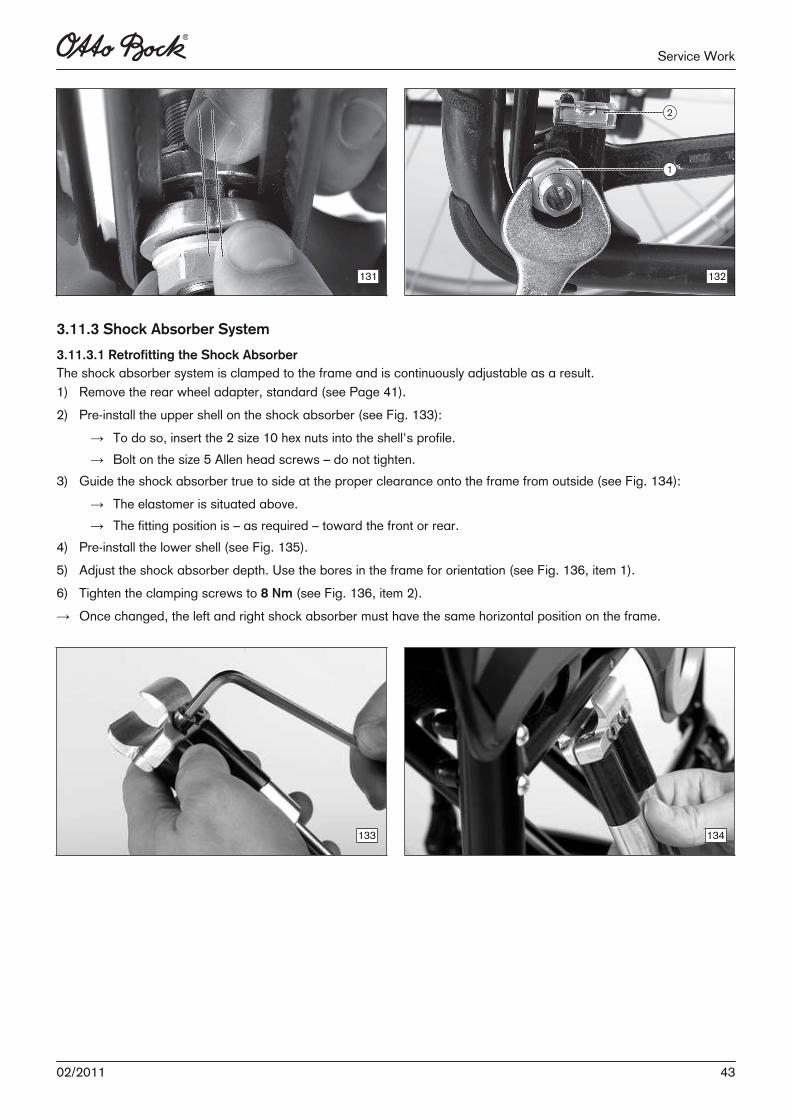
3.11.3 Shock Absorber System
3.11.3.1 Retrofitting the Shock AbsorberThe shock absorber system is clamped to the frame and is continuously adjustable as a result. 1) Remove the rear wheel adapter, standard (see Page 41).2) Pre-install the upper shell on the shock absorber (see Fig. 133):
→ To do so, insert the 2 size 10 hex nuts into the shell's profile.→ Bolt on the size 5 Allen head screws – do not tighten.
3) Guide the shock absorber true to side at the proper clearance onto the frame from outside (see Fig. 134):→ The elastomer is situated above.→ The fitting position is – as required – toward the front or rear.
4) Pre-install the lower shell (see Fig. 135).5) Adjust the shock absorber depth. Use the bores in the frame for orientation (see Fig. 136, item 1).6) Tighten the clamping screws to 8 Nm (see Fig. 136, item 2).→ Once changed, the left and right shock absorber must have the same horizontal position on the frame.
133 134
4302/2011
Service Work
135 136
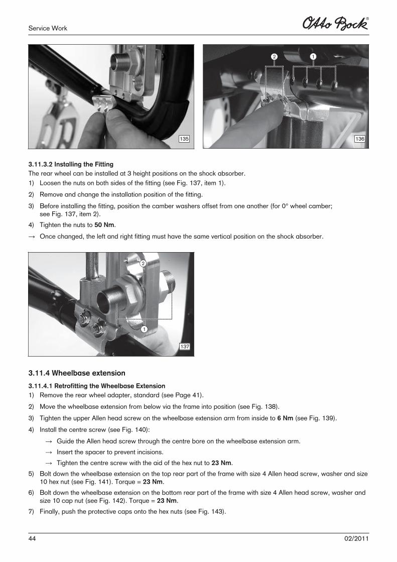
3.11.3.2 Installing the FittingThe rear wheel can be installed at 3 height positions on the shock absorber.1) Loosen the nuts on both sides of the fitting (see Fig. 137, item 1).2) Remove and change the installation position of the fitting.3) Before installing the fitting, position the camber washers offset from one another (for 0° wheel camber;
see Fig. 137, item 2).4) Tighten the nuts to 50 Nm.→ Once changed, the left and right fitting must have the same vertical position on the shock absorber.
137
3.11.4 Wheelbase extension
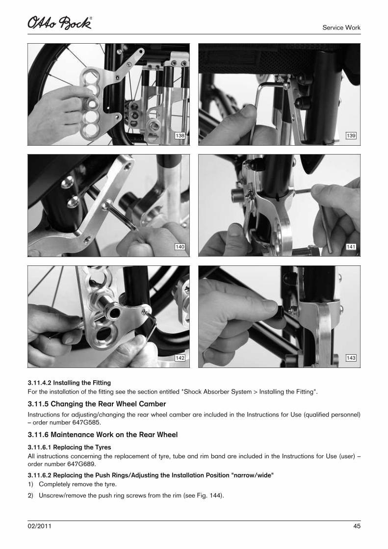
3.11.4.1 Retrofitting the Wheelbase Extension1) Remove the rear wheel adapter, standard (see Page 41).2) Move the wheelbase extension from below via the frame into position (see Fig. 138).3) Tighten the upper Allen head screw on the wheelbase extension arm from inside to 6 Nm (see Fig. 139).4) Install the centre screw (see Fig. 140):
→ Guide the Allen head screw through the centre bore on the wheelbase extension arm.→ Insert the spacer to prevent incisions.→ Tighten the centre screw with the aid of the hex nut to 23 Nm.
5) Bolt down the wheelbase extension on the top rear part of the frame with size 4 Allen head screw, washer and size10 hex nut (see Fig. 141). Torque = 23 Nm.
6) Bolt down the wheelbase extension on the bottom rear part of the frame with size 4 Allen head screw, washer andsize 10 cap nut (see Fig. 142). Torque = 23 Nm.
7) Finally, push the protective caps onto the hex nuts (see Fig. 143).
44 02/2011
Service Work
138 139
140 141
142 143
3.11.4.2 Installing the FittingFor the installation of the fitting see the section entitled "Shock Absorber System > Installing the Fitting".
3.11.5 Changing the Rear Wheel CamberInstructions for adjusting/changing the rear wheel camber are included in the Instructions for Use (qualified personnel)– order number 647G585.
3.11.6 Maintenance Work on the Rear Wheel
3.11.6.1 Replacing the TyresAll instructions concerning the replacement of tyre, tube and rim band are included in the Instructions for Use (user) –order number 647G689.3.11.6.2 Replacing the Push Rings/Adjusting the Installation Position "narrow/wide"1) Completely remove the tyre.2) Unscrew/remove the push ring screws from the rim (see Fig. 144).
4502/2011
Service Work
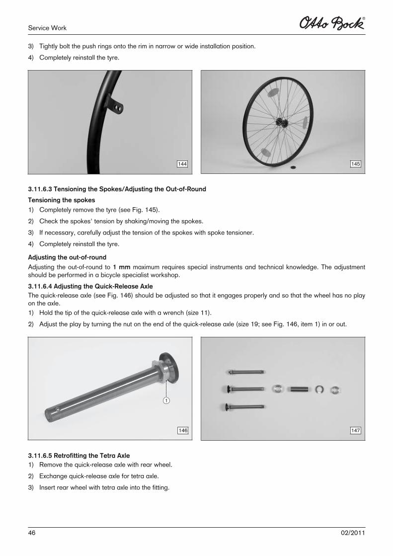
3) Tightly bolt the push rings onto the rim in narrow or wide installation position.4) Completely reinstall the tyre.
144 145
3.11.6.3 Tensioning the Spokes/Adjusting the Out-of-Round
Tensioning the spokes
1) Completely remove the tyre (see Fig. 145).2) Check the spokes' tension by shaking/moving the spokes.3) If necessary, carefully adjust the tension of the spokes with spoke tensioner.4) Completely reinstall the tyre.
Adjusting the out-of-round
Adjusting the out-of-round to 1 mm maximum requires special instruments and technical knowledge. The adjustmentshould be performed in a bicycle specialist workshop.3.11.6.4 Adjusting the Quick-Release AxleThe quick-release axle (see Fig. 146) should be adjusted so that it engages properly and so that the wheel has no playon the axle. 1) Hold the tip of the quick-release axle with a wrench (size 11).2) Adjust the play by turning the nut on the end of the quick-release axle (size 19; see Fig. 146, item 1) in or out.
146 147
3.11.6.5 Retrofitting the Tetra Axle1) Remove the quick-release axle with rear wheel.2) Exchange quick-release axle for tetra axle.3) Insert rear wheel with tetra axle into the fitting.
46 02/2011
Service Work
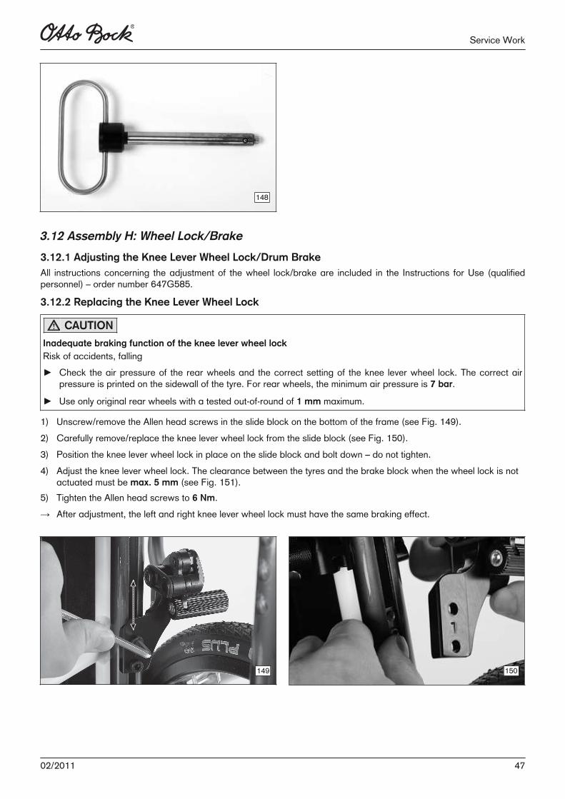
148
3.12 Assembly H: Wheel Lock/Brake
3.12.1 Adjusting the Knee Lever Wheel Lock/Drum BrakeAll instructions concerning the adjustment of the wheel lock/brake are included in the Instructions for Use (qualifiedpersonnel) – order number 647G585.
3.12.2 Replacing the Knee Lever Wheel Lock
CAUTION
Inadequate braking function of the knee lever wheel lockRisk of accidents, falling► Check the air pressure of the rear wheels and the correct setting of the knee lever wheel lock. The correct air
pressure is printed on the sidewall of the tyre. For rear wheels, the minimum air pressure is 7 bar.
► Use only original rear wheels with a tested out-of-round of 1 mm maximum.
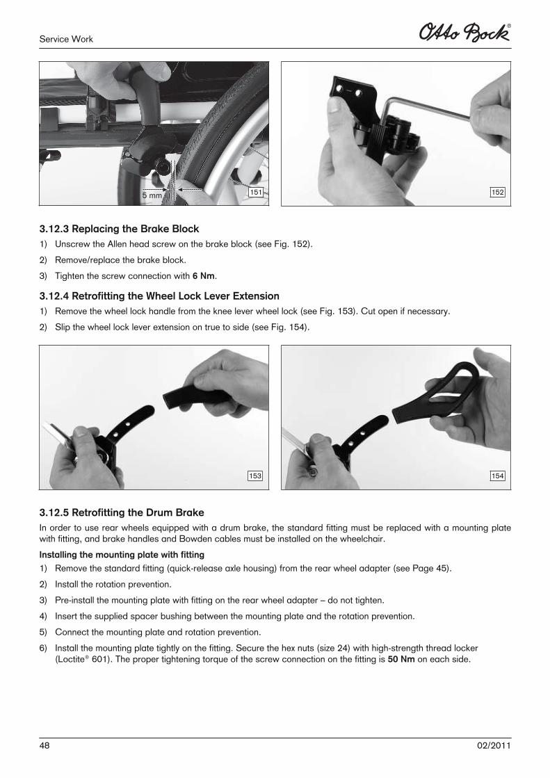
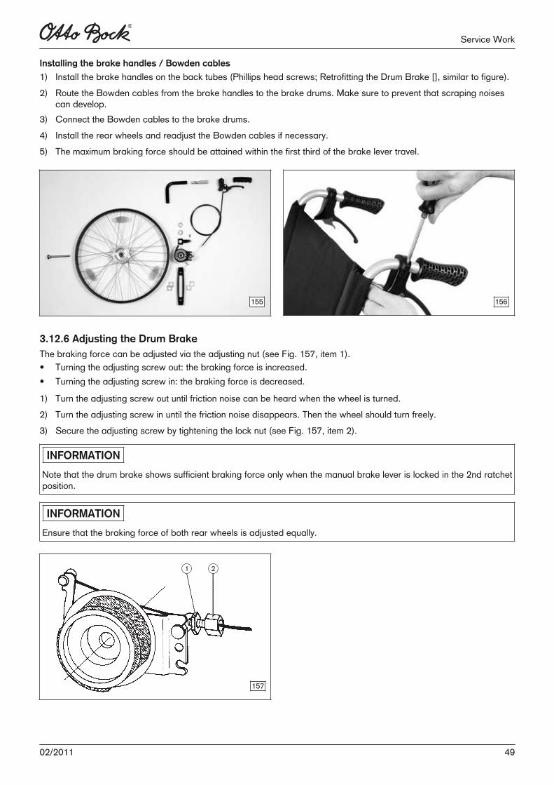
1) Unscrew/remove the Allen head screws in the slide block on the bottom of the frame (see Fig. 149).2) Carefully remove/replace the knee lever wheel lock from the slide block (see Fig. 150).3) Position the knee lever wheel lock in place on the slide block and bolt down – do not tighten.4) Adjust the knee lever wheel lock. The clearance between the tyres and the brake block when the wheel lock is not
actuated must be max. 5 mm (see Fig. 151).5) Tighten the Allen head screws to 6 Nm.→ After adjustment, the left and right knee lever wheel lock must have the same braking effect.
149 150
4702/2011
Service Work
5 mm151 152
3.12.3 Replacing the Brake Block1) Unscrew the Allen head screw on the brake block (see Fig. 152).2) Remove/replace the brake block.3) Tighten the screw connection with 6 Nm.
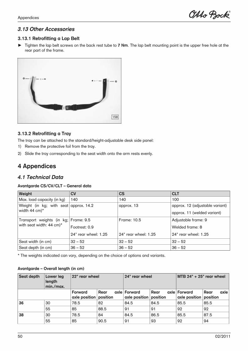
3.12.4 Retrofitting the Wheel Lock Lever Extension1) Remove the wheel lock handle from the knee lever wheel lock (see Fig. 153). Cut open if necessary.2) Slip the wheel lock lever extension on true to side (see Fig. 154).
153 154
3.12.5 Retrofitting the Drum BrakeIn order to use rear wheels equipped with a drum brake, the standard fitting must be replaced with a mounting platewith fitting, and brake handles and Bowden cables must be installed on the wheelchair.Installing the mounting plate with fitting
1) Remove the standard fitting (quick-release axle housing) from the rear wheel adapter (see Page 45).2) Install the rotation prevention.3) Pre-install the mounting plate with fitting on the rear wheel adapter – do not tighten. 4) Insert the supplied spacer bushing between the mounting plate and the rotation prevention.5) Connect the mounting plate and rotation prevention.6) Install the mounting plate tightly on the fitting. Secure the hex nuts (size 24) with high-strength thread locker
(Loctite® 601). The proper tightening torque of the screw connection on the fitting is 50 Nm on each side.
48 02/2011
Service Work
Installing the brake handles / Bowden cables
1) Install the brake handles on the back tubes (Phillips head screws; Retrofitting the Drum Brake [], similar to figure).2) Route the Bowden cables from the brake handles to the brake drums. Make sure to prevent that scraping noises
can develop.3) Connect the Bowden cables to the brake drums.4) Install the rear wheels and readjust the Bowden cables if necessary. 5) The maximum braking force should be attained within the first third of the brake lever travel.
155 156
3.12.6 Adjusting the Drum BrakeThe braking force can be adjusted via the adjusting nut (see Fig. 157, item 1). • Turning the adjusting screw out: the braking force is increased.• Turning the adjusting screw in: the braking force is decreased.
1) Turn the adjusting screw out until friction noise can be heard when the wheel is turned. 2) Turn the adjusting screw in until the friction noise disappears. Then the wheel should turn freely.3) Secure the adjusting screw by tightening the lock nut (see Fig. 157, item 2).
INFORMATION
Note that the drum brake shows sufficient braking force only when the manual brake lever is locked in the 2nd ratchetposition.
INFORMATION
Ensure that the braking force of both rear wheels is adjusted equally.
157
4902/2011
Service Work
3.13 Other Accessories
3.13.1 Retrofitting a Lap Belt► Tighten the lap belt screws on the back rest tube to 7 Nm. The lap belt mounting point is the upper free hole at the
rear part of the frame.
158
3.13.2 Retrofitting a TrayThe tray can be attached to the standard/height-adjustable desk side panel:1) Remove the protective foil from the tray.2) Slide the tray corresponding to the seat width onto the arm rests evenly.
4 Appendices
4.1 Technical Data
Avantgarde CS/CV/CLT – General data
Weight CV CS CLTMax. load capacity (in kg) 140 140 100Weight (in kg; with seatwidth 44 cm)*
approx. 14.2 approx. 13 approx. 12 (adjustable variant)approx. 11 (welded variant)
Transport weights (in kg;with seat width: 44 cm)*
Frame: 9.5Footrest: 0.924" rear wheel: 1.25
Frame: 10.5
24" rear wheel: 1.25
Adjustable frame: 9Welded frame: 824" rear wheel: 1.25
Seat width (in cm) 32 – 52 32 – 52 32 – 52Seat depth (in cm) 36 – 52 36 – 52 36 – 52
* The weights indicated can vary, depending on the choice of options and variants.
Avantgarde – Overall length (in cm)
Seat depth Lower leglengthmin./max.
22" rear wheel 24" rear wheel MTB 24" + 25" rear wheel
Forwardaxle position
Rear axleposition
Forwardaxle position
Rear axleposition
Forwardaxle position
Rear axleposition
30 78.5 82 84.5 84.5 85.5 85.53655 85 88.5 91 91 92 9230 78.5 84 84.5 86.5 85.5 87.53855 85 90.5 91 93 92 94
50 02/2011
Appendices

Seat depth Lower leglengthmin./max.
22" rear wheel 24" rear wheel MTB 24" + 25" rear wheel
30 78.5 86 84.5 88.5 85.5 89.54055 85 92.5 91 95 92 9630 78.5 88 84.5 90.5 84.5 91.54255 85 94.5 91 97 92 9830 78.5 90 84.5 92.5 85.5 93.54455 85 96.5 91 99 92 10030 80.5 92 84.5 94.5 85.5 95.54655 87 98.5 91 101 92 10230 82 94 84.5 96.5 85.5 97.54855 88.5 100.5 91 103 92 10430 84 96 86.5 98.5 87.5 99.55055 90.5 102.5 93 105 94 10630 86 98 88.5 100.5 89.5 101.55255 92.5 104.5 95 107 96 108
With wheelbase extension: Rear axle position + 9.5 cm.
Avantgarde CS/CLT – Overall length (in cm)
Seat depth 22" rear wheel 24" rear wheel MTB 24" + 25" rear wheelForward axleposition
Rear axle position
Forward axleposition
Rear axle position
Forward axleposition
Rear axle position
36–42 72 92.5 77.5 95 78.5 9644–48 76 96.5 77.5 99 78.5 10050–52 80 100.5 82.5 103 83.5 104
With wheelbase extension: Rear axle position +9.5 cm.For CLT Ultra model: Rear axle position -2 cm.
Avantgarde CV/CS/CLT – Overall width with rear wheel with hollow rim (in cm)
Seat width Side panels Standard and Clothing protector Desk side panel with armrest, height-adjustable32 49 50.534 51 52.536 53 54.538 55 56.540 57 58.542 59 60.544 61 62.546 63 64.548 65 66.550 67 68.552 69 70.5
1) For narrow push ring mounting position and 0° camber of the rear wheels (add +2 cm for wide mounting position).For installation of drive wheel with Infinity Ultralight rim: Overall width -1 cm.For installation of rear wheel with Spinergy SPOX rim and rear wheel with attendant wheel lock: Overall width +1 cm.
5102/2011
Appendices
Increase in overall width because of camber setting of the rear wheels (all models, in cm)
Wheel camber 22" rear wheel 24" rear wheel 25" rear wheel0" < 4 4 > 42" < 8 8 > 8
Folded dimensions, including rear wheels
from 26 cm
Avantgarde CS/CV/CLT – Lower leg length (in cm)
Measured from top of seat cover to top of footrest (Lower leg length minus thickness of seat cushion used)
Short lower leg length 16–31Lower leg length 30–55
Avantgarde CV/CS/CLT – Front seat height (in cm)
The front seat height depends on the selected wheel size, front wheel fork and mounting position.
Front wheel with frontwheel fork, short
Adjustment range
With adapter for small frontseat heights
With adapter for largefront seat heights
Without seat height adapter
3“ 38.5 – 40 45.5 – 47 42 – 434“ 39 – 41 46 – 48 42 – 455“ 40 – 42.5 47 – 49.5 43.5 – 465.5“ 41 – 43 48 – 50 44 – 476“ 42.5 – 44 49.5 – 51 46 – 477“ 45 52 48.5
Front wheel with frontwheel fork, long
Adjustment range
With adapter for small frontseat heights
With adapter for largefront seat heights
Without seat height adapter
3“ 42 – 43 49 – 50 46 – 474“ 42.5 – 45 49.5 – 52 46 – 48.55“ 42.5 – 46 49.5 – 53 46 – 505.5“ 43 – 47 50 – 54 47 – 50.56“ 44 – 47.5 51 – 54.5 47 – 517“ 45 – 48.5 52 – 55.5 48.5 – 52
Figures without seat cushion at 0° seat angle.The figures shown are rounded values which have been theoretically determined. Max. deviation 1 cm.
52 02/2011
Appendices
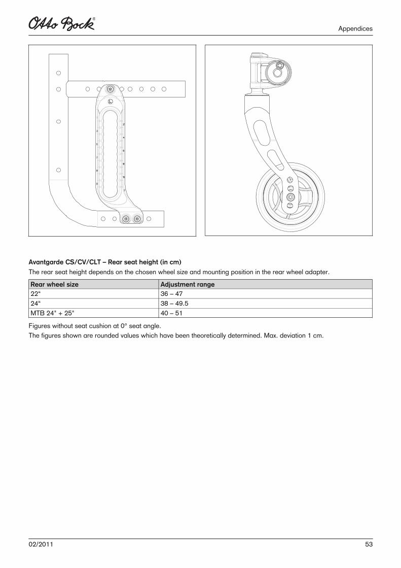
Avantgarde CS/CV/CLT – Rear seat height (in cm)
The rear seat height depends on the chosen wheel size and mounting position in the rear wheel adapter.
Rear wheel size Adjustment range22“ 36 – 4724“ 38 – 49.5MTB 24" + 25" 40 – 51
Figures without seat cushion at 0° seat angle.The figures shown are rounded values which have been theoretically determined. Max. deviation 1 cm.
5302/2011
Appendices

54 02/2011

Kundenservice/Customer Service
Europe
Otto Bock HealthCare Deutschland GmbHMax-Näder-Str. 15 · D–37115 Duderstadt Tel. +49 5527 848-3433 · Fax +49 5527 848-1460e-mail: [email protected] · www.ottobock.com
Otto Bock Healthcare Products GmbHKaiserstraße 39 · A–1070 Wien Tel. +43-1 523 37 86 · Fax +43-1 523 22 64 e-mail: [email protected] · www.ottobock.com
Otto Bock Suisse AGPilatusstrasse 2 · CH–6036 Dierikon Tel. +41 41 4556171 · Fax +41 41 4556170 e-mail: [email protected]
Otto Bock Healthcare plc 32, Parsonage Road · Englefield Green GB–Egham, Surrey TW20 0LD Tel. +44 1784 744900 · Fax +44 1784 744901 e-mail: [email protected] · www.ottobock.co.uk
Otto Bock France SNC4 Rue de la Réunion · B.P. 11 F–91941 Les Ulis Cedex Tél. +33 1 69188830 · Fax +33 1 69071802 e-mail: [email protected] · www.ottobock.fr
Otto Bock Italia S.R.LVia Filippo Turati 5/7 · I–40054 Budrio (BO) Tel. +39 051 692-4711 · Fax +39 051 692-4720 e-mail: [email protected] · www.ottobock.it
Otto Bock Iberica S.A.C/Majada, 1 · E–28760 Tres Cantos (Madrid) Tel. +34 91 8063000 · Fax +34 91 8060415 e-mail: [email protected] · www.ottobock.es
Industria Ortopédica Otto Bock Unip. Lda.Av. Miguel Bombarda, 21 - 2º Esq. P–1050-161 Lisboa Tel.: +351 21 3535587 · Fax: +351 21 3535590 e-mail: [email protected]
Otto Bock Benelux B.V.Ekkersrijt 1412 · NL–5692 AK-Son en Breugel Tel. +31 499 474585 · Fax +31 499 4762 50 e-mail: [email protected]
Otto Bock Scandinavia ABKoppargatan 3 · Box 623 · S–60114 Norrköping Tel. +46 11 280600 · Fax +46 11 312005 e-mail: [email protected] · www.ottobock.se
OOO Otto Bock Service p/o Pultikovo, Business Park „Greenwood“, Building 7, 69 km MKAD RUS–143441 Moscow Region/Krasnogorskiy Rayon Tel. +7 495 564-8360 · Fax +7 495 564-8363 e-mail: [email protected] · www.ottobock.ru
Otto Bock Hungária Kft.Tatai út 74. · H–1135 Budapest Tel. +36 1 4 5110 20 · Fax +36 1 4 5110 21 e-mail: [email protected] · www.ottobock.hu
Otto Bock Polska Sp. z o. o.Ulica Koralowa 3 · PL–61-029 Poznań Tel. +48 61 6538250 · Fax +48 61 6538031 e-mail: [email protected] · www.ottobock.pl
Otto Bock ČR s.r.o.Protetická 460 · CZ–33008 Zruč-Senec Tel. +420 37 7825044 · Fax +420 37 7825036 e-mail: [email protected] · www.ottobock.cz
Otto Bock Slovakia s.r.o.Röntgenova 26 · SK–851 01 Bratislava 5Slovak RepublicTel. +421 2 32 78 20 70 · Fax +421 2 32 78 20 89e-mail: [email protected] · www.ottobock.sk
Otto Bock Romania srl Șos de Centura Chitila-Mogoșoia Nr. 3RO–Chitila 077405, Jud. Ilfov Tel: +40 21 4363110 · Fax: +40 21 4363023 [email protected] · www.ottobock.ro
Otto Bock Bulgaria Ltd. 41 Tzar Boris III- Blvd. · BG–1612 Sofia Tel. + 359 2 80 57 980 · Fax + 359 2 80 57 982 e-mail: [email protected] · www.ottobock.bg
Otto Bock Adria D.O.O.Dr. Franje Tuđmana 14 · HR–10431 Sveta Nedelja Tel. +385 1 3361544 · Fax +385 1 3365986 e-mail: [email protected] · www.ottobock.hr
Otto Bock Adria Sarajevo D.O.O.Omladinskih radnih brigada 5 · BIH–71000 Sarajevo Tel. +387 33 766200 · Fax +387 33 766201 [email protected] · www.ottobockadria.com.ba
Otto Bock Sava d.o.o.Maksima Gorkog bb · 18000 Niš, Republika SrbijaTel./Fax +381 18 539 191e-mail: [email protected] · www.ottobock.rs
Otto Bock Ortopedi ve Rehabilitasyon Tekniği Ltd. Şti.Ali Dursun Bey Caddesi · Lati Lokum Sokak Meriç Sitesi B Block No: 6/1 TR–34387 Mecidiyeköy-İstanbul Tel. + 90 212 3565040 · Fax +90 212 3566688 e-mail: [email protected] · www.ottobock.com.tr
Otto Bock Algérie E.U.R.L.32, rue Ahcène outalab - Coopérative les Mimosas Mackle-Ben Aknoun - Alger · DZ–Algérie Tel. +213 21 913863 · Fax +213 21 913863e-mail: [email protected] · www.ottobock.fr
Otto Bock Egypt S.A.E.115, El- Alameen St. · Mohandeseen – Giza · ET–EgyptTel. +202 330 24 390 · Fax +202 330 24 380e-mail: [email protected] · www.ottobock.com.eg
Americas
Otto Bock Argentina S.A.Piedras, 1314 - Código Postal: RA–1147 Ciudad Autônoma de Buenos Aires Tel. + 54 11 4300 0076 e-mail: [email protected]
Otto Bock do Brasil Ltda.Rua Jovelino Aparecido Miguel, 32 BR–13051-030 Campinas-São Paulo Tel. +55 19 3729 3500 · Fax +55 19 32 69 6061 e-mail: [email protected] · www.ottobock.com.br
Otto Bock HealthCare Canada Ltd. 5470 Harvester Rd, Burlington, Ontario L7L 5N5 CA–Canada Tel. +1 289 288-4848 · Fax +1 289 288-4837 e-mail: [email protected] · www.ottobock.ca
Otto Bock HealthCare Andina Ltda.Clínica Universitária Teletón, Autopista Norte km 21 La Caro · Chia, Cundinamarca Bogotá / Colombia Tel. +57 1 8619988 · Fax +57 1 8619977 e-mail: [email protected]
Otto Bock de Mexico S.A. de C.V.Av. Avila Camacho 2246 · Jardines del Country MEX–Guadalajara, Jal. 44210 Tel. +52 33 38246787 · Fax +52 33 38531935 e-mail: [email protected] www.ottobock.com.mx
Otto Bock HealthCare LPTwo Carlson Parkway North, Suite 100 U.S.A.–Minneapolis, Minnesota 55447 Phone +1 800 328 4058 · Fax +1 800 962 2549 e-mail: [email protected] www.ottobockus.com
Asia/PacificOtto Bock Australia Pty. Ltd.Suite 1.01, Century Corporate Centre 62 Norwest Boulevarde · Norwest Business Park AUS–Baulkham Hills NSW 2153 Tel. +61 2 88182800 · Fax +61 2 88182898 e-mail: [email protected] www.ottobock.com.au
Beijing Otto Bock Orthopaedic Industries Co., Ltd.B12E, Universal Business Park 10 Jiuxianqiao Road, Chaoyang District Beijing 100015 · P.R.China Tel. +86 10 85986880 · Fax +86 10 85980040 e-mail: [email protected] · www.ottobock.com.cn
Otto Bock Asia Pacific Ltd.Suite 3218, 32/F., Sun Hung Kai Centre 30 Harbour Road, Wanchai · Hong Kong Tel No. +852 2598 9772 · Fax No. +852 2598 7886 e-mail: [email protected]
Otto Bock HealthCare India Pvt. Ltd.Behind Fairlawn Housing Society Sion Trombay Road Chembur · IND–Mumbai 400 071 Tel. +91 22 2520 1268 · Fax +91 22 2520 1267 e-mail: [email protected] www.ottobockindia.com
Otto Bock Japan K. K. Yokogawa Building 8F · 4-4-44 Shibaura, Minato-ku J–Tokyo 108-0023 Tel. +81 3 3798-2111 · Fax +81 3 3798-2112 e-mail: [email protected]
Otto Bock Korea HealthCare Inc. Beakyoung B/D 2FL · 37-22, Samsung-dongGangnam-gu · ROK–Seoul 135-090 Tel. +82 2 577-3831 · Fax +82 2 577-3828 e-mail: [email protected]
Otto Bock South East Asia Co. Ltd. 1741 Phaholyothin Road, Kwaeng Chatuchark, Khet Chatuchark, T–Bangkok 10900 Tel. +66 2 930 3030 · Fax +66 2 930 3311 e-mail: [email protected]
Other countries
Otto Bock HealthCare GmbHMax-Näder-Str. 15 · D–37115 Duderstadt Tel. +49 5527 848-1590 · Fax +49 5527 848-1676 e-mail: [email protected] · www.ottobock.com

Versandanschrift für Rücksendungen/Adress for Returns:
Otto Bock Manufacturing Königsee GmbH
Lindenstraße 13 · 07426 Königsee/Germany
Otto Bock has a certified Quality Management System in accordance with ISO 13485.
Hersteller/Manufacturer:
Otto Bock Mobility Solutions GmbH
Lindenstraße 13 · 07426 Königsee/GermanyPhone +49 69 9999 9393 · Fax +49 69 9999 9392
[email protected] · www.ottobock.com