Embed Size (px)
Citation preview
AQRB, April, 2006
Avalanche Diodes (APD) Detectors:
Introduction and Recent Advances*
Alfred Q.R. BaronHarima RIKEN & SPring-8/JASRI
International Symposium on the Development of Detectors for Particle, Astro-Particle, and Synchrotron Radiation Experiments
“SNIC”SLAC, Stanford, April 2006
*Focus on Fast X-Ray Detection
AQRB, April, 2006
A Change in Scale…
Compared to the detector effort in high-energy physics, theeffort in synchrotron radiation is in its childhood,
… and the APD effort in x-ray scattering is nearly a newborn.
Small efforts: ESRF, BNL, DESY, SPring-8, KEK, (SSRL)& the recent addition of a dedicated technician
at ESRF is already a major jump.
AQRB, April, 2006
Historical
Development in the 60s & 70s(Huth, McIntyre, Webb, Jones at GE & RCA)
Some discussion of a “Solid State Photomultiplier”(but gain not so high…)
Main utility is high speed (large gain-bandwidth product).Optical Communication, Laser range-finding…
& Applications where for some reason a PMT is not suitablePositron Emission Tomography (High Magnetic Field)
Introduced to the x-ray scattering community via
Nuclear Resonant Scattering (NRS) of Synchrotron Radiation
1990’s
AQRB, April, 2006
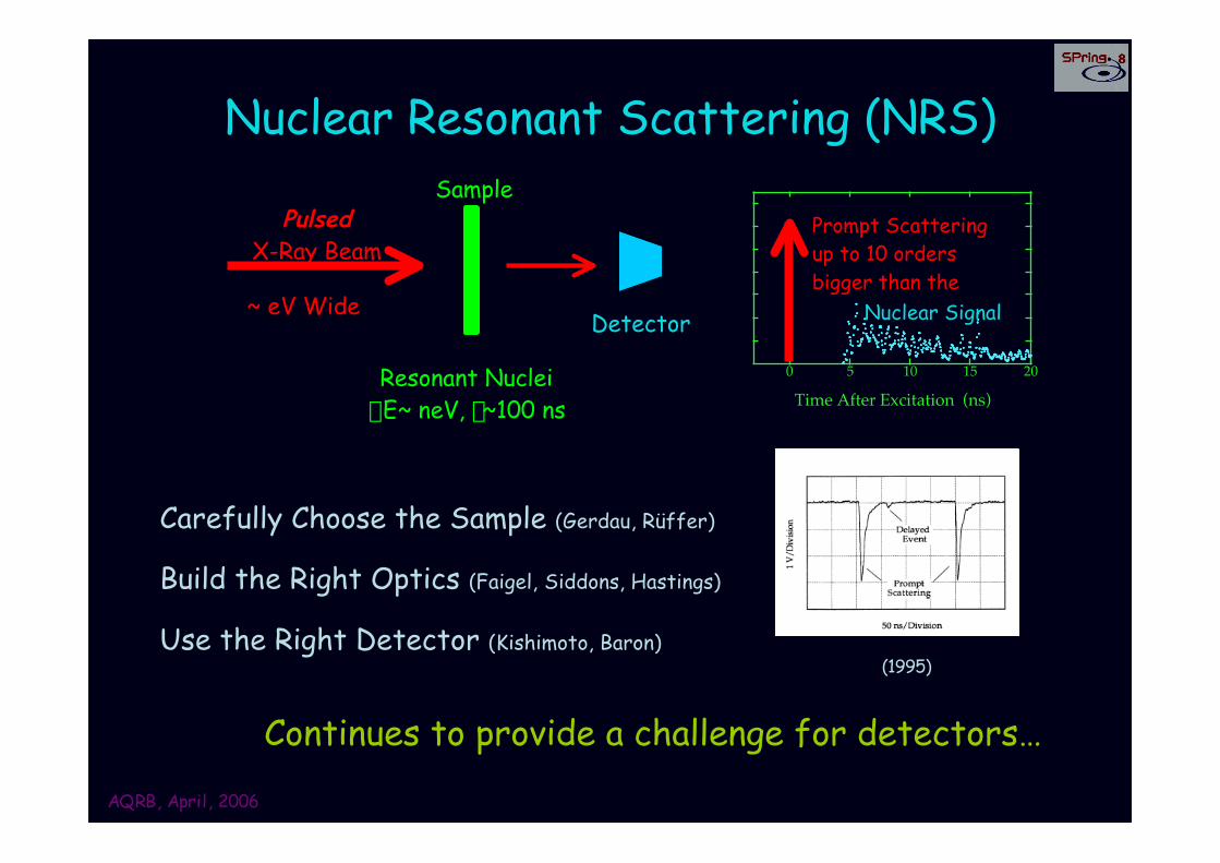
Nuclear Resonant Scattering (NRS)
PulsedX-Ray Beam
~ eV Wide
Resonant NucleiDE~ neV, t~100 ns
Detector
0 5 10 15 20
Time After Excitation (ns)
Prompt Scatteringup to 10 ordersbigger than the
Nuclear Signal
Carefully Choose the Sample (Gerdau, Rüffer)
Build the Right Optics (Faigel, Siddons, Hastings)
Use the Right Detector (Kishimoto, Baron)(1995)
Continues to provide a challenge for detectors…
Sample
AQRB, April, 2006
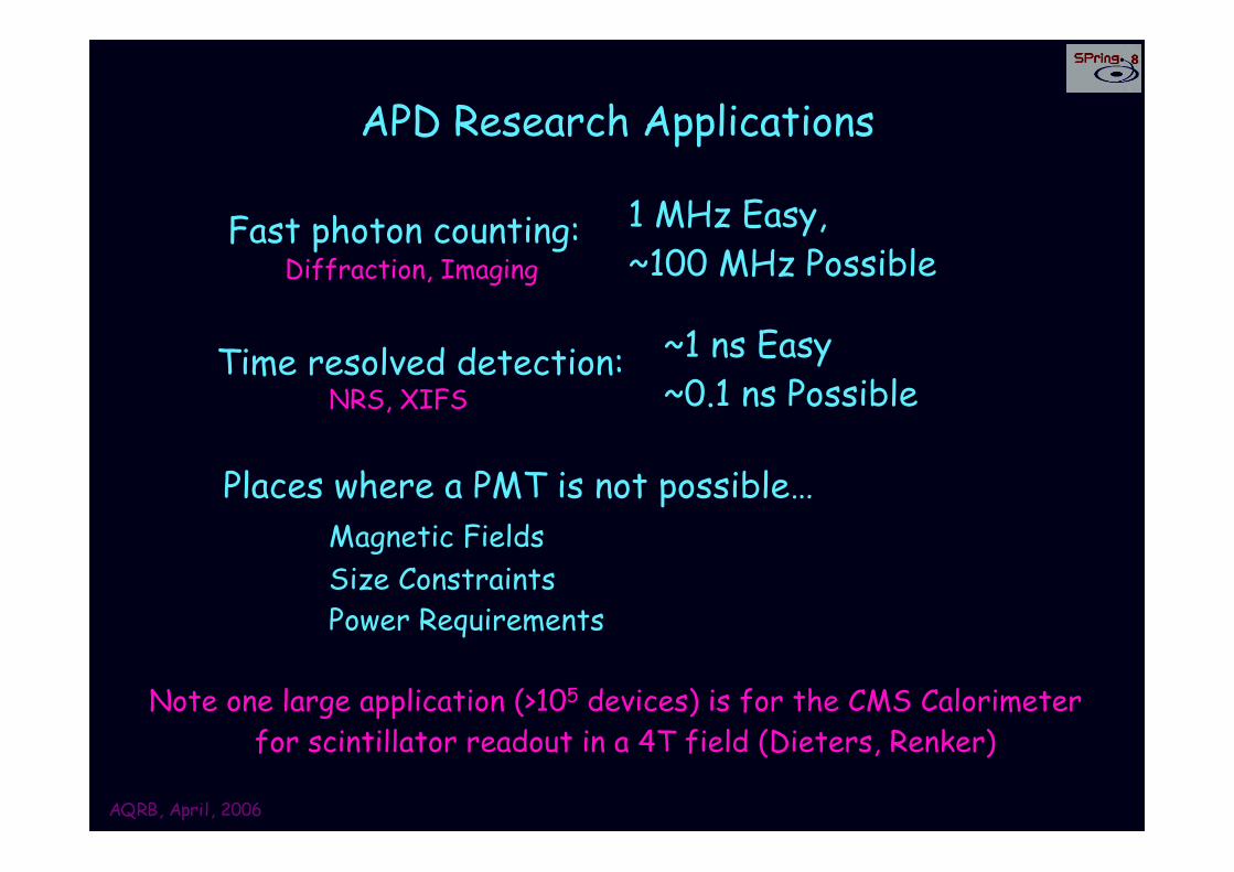
APD Research Applications
Fast photon counting:
Time resolved detection:
Places where a PMT is not possible…Magnetic Fields Size ConstraintsPower Requirements
1 MHz Easy, ~100 MHz Possible
~1 ns Easy~0.1 ns Possible
Note one large application (>105 devices) is for the CMS Calorimeter for scintillator readout in a 4T field (Dieters, Renker)
NRS, XIFS
Diffraction, Imaging

AQRB, April, 2006
A Diode With Gain
Drift Region102-104 V/cm
Avalanche Region~105 V/cm
eh
x-ray
Absorption10-200 um Si
Drift~ 10 ps/um
Gain 101-104
Limited Stopping Power
~50 TypicalIntrinsic (excess) noise dueto amplification of BOTH
Electrons & Holes
Depleted
10 keV X-Rays -> OK20 keV -> Losses
“McIntyre” Theory (~1970)
1 2 3

AQRB, April, 2006
Geiger vs Linear Operation
Linear Operation:Diode biased below breakdown.Well defined small-signal gain.
Diode biased above breakdown.Single electron leads to run-away
gain until quenched.Noisy: 102-105 cps/channel
Geiger Operation:
(also Poster/Abs 143, Renker)
AQRB, April, 2006
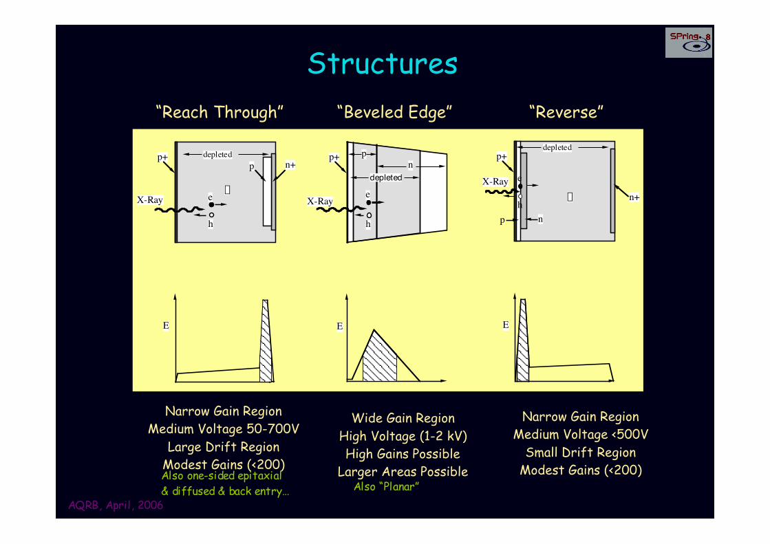
Structures
X-Ray e
h
p+p n+
pX-Ray
h
p+ pn
edepleted
depleted
X-Ray
p+
p n
p
depleted
e
hn+
(a) Reach Through (b) Beveled Edge (c) Reverse Reach Through
E E E
“Reach Through” “Reverse”“Beveled Edge”
Narrow Gain RegionMedium Voltage 50-700V
Large Drift RegionModest Gains (<200)
Wide Gain RegionHigh Voltage (1-2 kV)High Gains Possible
Larger Areas Possible
Narrow Gain RegionMedium Voltage <500V
Small Drift RegionModest Gains (<200)Also one-sided epitaxial
& diffused & back entry… Also “Planar”
AQRB, April, 2006
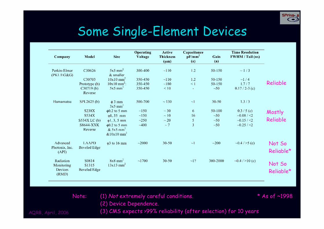
Some Single-Element Devices
Reliable
MostlyReliable
Not SoReliable*
Not SoReliable*
* As of ~1998Note: (1) Not extremely careful conditions.(2) Device Dependence.(3) CMS expects >99% reliability (after selection) for 10 years
AQRB, April, 2006
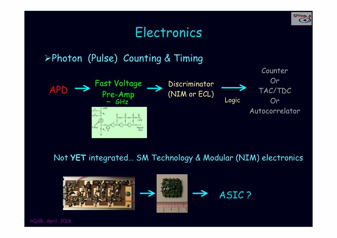
Electronics
ÿPhoton (Pulse) Counting & Timing
APDFast Voltage
Pre-Amp ~ GHz
Discriminator(NIM or ECL)
Logic
CounterOr
TAC/TDCOr
Autocorrelator
Not YET integrated… SM Technology & Modular (NIM) electronics
+HV
X-Ray
+12V
Signal Out
C
R
R 1
2
C
Older: ~1 GHz, 2 dBm
ASIC ?
AQRB, April, 2006
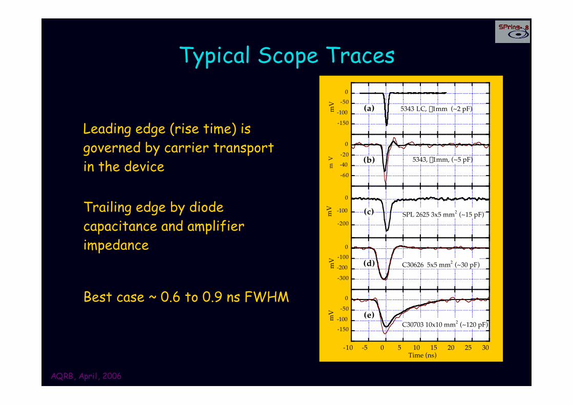
Typical Scope Traces
-150-100
-500
mV 5343 LC, f1mm (~2 pF) (a)
-60-40-20
0
5343, f1mm, (~5 pF)
mV (b)
-200
-100
0
mV
SPL 2625 3x5 mm2 (~15 pF) (c)
-300-200-100
0
mV C30626 5x5 mm2 (~30 pF) (d)
-150-100
-500
-10 -5 0 5 10 15 20 25 30
mV
C30703 10x10 mm2 (~120 pF)
Time (ns)
(e)
Leading edge (rise time) isgoverned by carrier transportin the device
Trailing edge by diodecapacitance and amplifierimpedance
Best case ~ 0.6 to 0.9 ns FWHM
AQRB, April, 2006
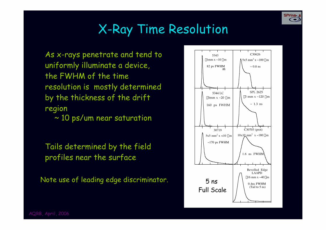
X-Ray Time Resolution
5343 f1mm x ~10 mm
82 ps FWHM
5344 LC f3mm x ~20 mm
160 ps FWHM
30719
5x5 mm2 x <10 mm
~170 ps FWHM
B
C30626
5x5 mm2 x ~100 mm
~ 0.8 ns
SPL 2625f3 mm x ~120 mm
~ 1.3 ns
C30703 (prot)
10x10 mm2 x ~180 mm
1.6 ns FWHM
Bevelled EdgeLAAPD
f16 mm x ~40 mm
0.4ns FWHM (Tail to 5 ns)
~ 10 ps/um near saturation
As x-rays penetrate and tend touniformly illuminate a device,the FWHM of the timeresolution is mostly determinedby the thickness of the driftregion
Tails determined by the fieldprofiles near the surface
5 ns Full Scale
Note use of leading edge discriminator.
AQRB, April, 2006
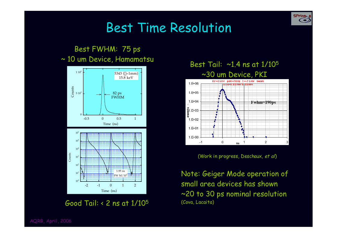
Best Time Resolution
100
101
102
103
104
105
106
-2 -1 0 1 2
Coun
ts
Time (ns)
1.95 nsFW M/105
0
5 105
1 106
-0.5 0 0.5 1
5343 (f=1mm)15.8 keV
Coun
ts
Time (ns)
82 ps FWHM
Best FWHM: 75 ps~ 10 um Device, Hamamatsu
Good Tail: < 2 ns at 1/105
Best Tail: ~1.4 ns at 1/105
~30 um Device, PKI
(Work in progress, Deschaux, et al)
Note: Geiger Mode operation ofsmall area devices has shown~20 to 30 ps nominal resolution(Cova, Lacaita)
AQRB, April, 2006
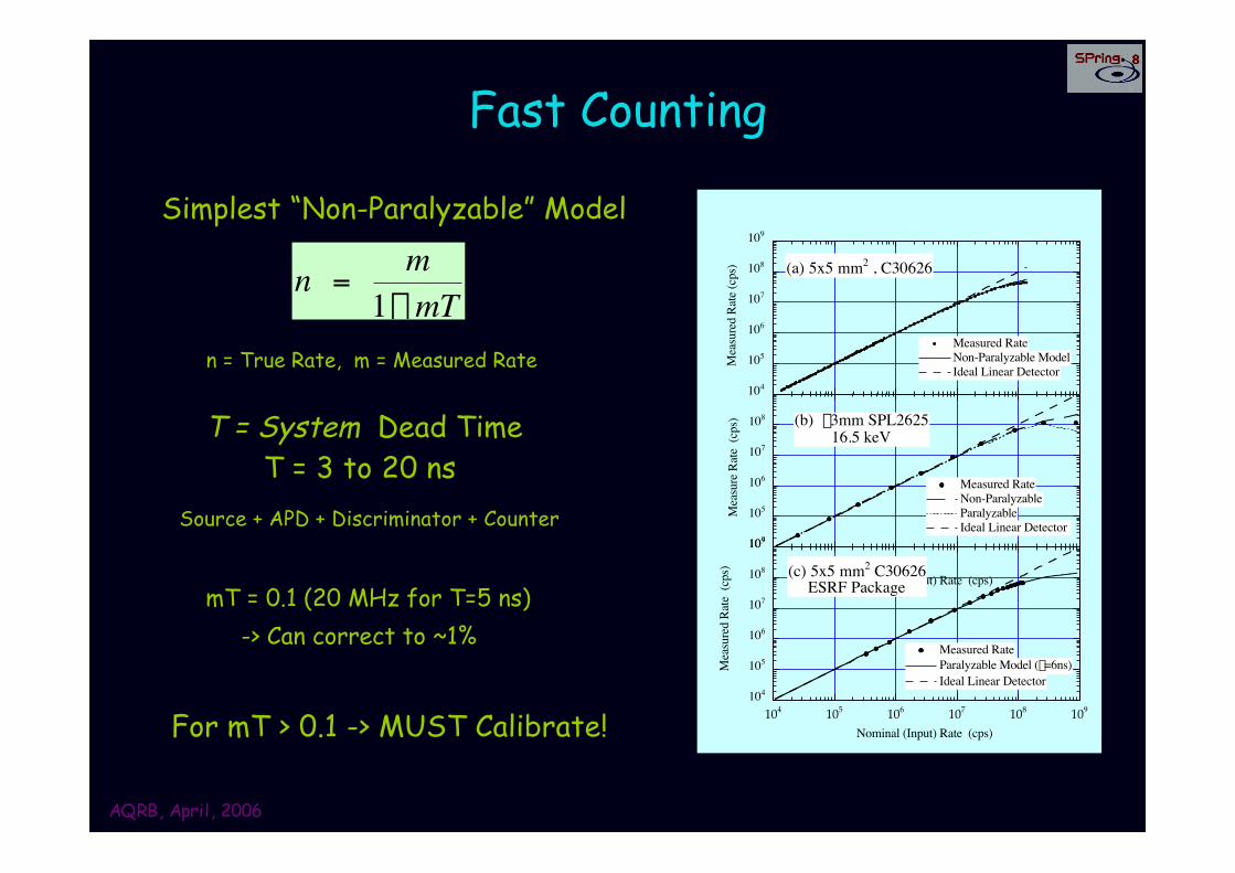
Fast Counting
104
105
106
107
108
109
Measured RateNon-Paralyzable ModelIdeal Linear Detector
Mea
sure
d Ra
te (c
ps) (a) 5x5 mm2 , C30626
104
105
106
107
108
Measured RateNon-ParalyzableParalyzableIdeal Linear Detector
Mea
sure
Rat
e (c
ps)
Nominal (Input) Rate (cps)
(b) f3mm SPL262516.5 keV
104
105
106
107
108
109
Measured RateParalyzable Model (t=6ns)Ideal Linear Detector
104 105 106 107 108 109
Mea
sure
d Ra
te (
cps) (c) 5x5 mm2 C30626
ESRF Package
Nominal (Input) Rate (cps)
Simplest “Non-Paralyzable” Model
†
n = m1- mT
n = True Rate, m = Measured Rate
T = System Dead TimeT = 3 to 20 ns
mT = 0.1 (20 MHz for T=5 ns) -> Can correct to ~1%
Source + APD + Discriminator + Counter
For mT > 0.1 -> MUST Calibrate!
AQRB, April, 2006
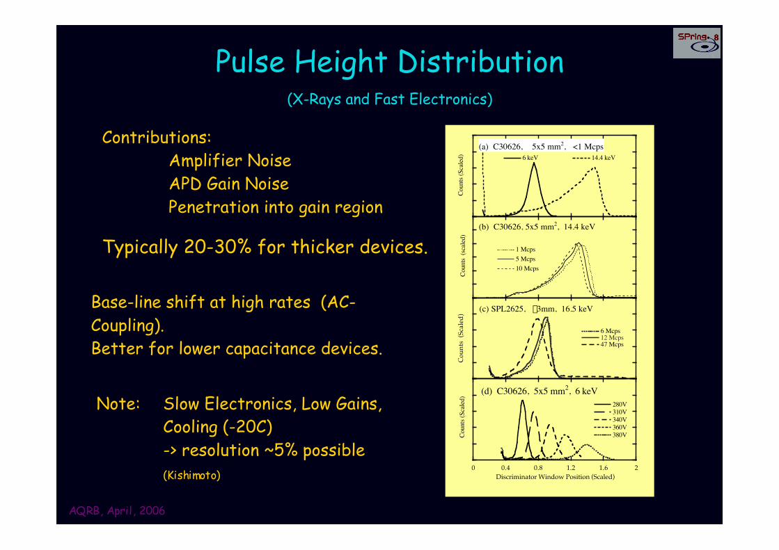
Pulse Height Distribution(X-Rays and Fast Electronics)
6 keV 14.4 keV(a) C30626, 5x5 mm2, <1 Mcps
Coun
ts (S
caled
)
1 Mcps5 Mcps10 Mcps
Coun
ts (s
caled
)
(b) C30626, 5x5 mm2, 14.4 keV
6 Mcps12 Mcps47 Mcps
Coun
ts (
Scal
ed) (c) SPL2625, f3mm, 16.5 keV
280V310V340V360V380V
0 0.4 0.8 1.2 1.6 2Co
unts
(Sca
led) (d) C30626, 5x5 mm2, 6 keV
Discriminator Window Position (Scaled)
Typically 20-30% for thicker devices.
Base-line shift at high rates (AC-Coupling).Better for lower capacitance devices.
Contributions:Amplifier NoiseAPD Gain NoisePenetration into gain region
Note: Slow Electronics, Low Gains,Cooling (-20C) -> resolution ~5% possible(Kishimoto)
AQRB, April, 2006
Other Points
Low T operation is possible - increased gain and T-sensitivity ~ 40K with API Beveled Edge (Yang)~ 100K with Ham. Rev. APD (Dorokhov)
Electron Detection is possible - note radiation damage!Hamamatsu Devices with special surface (Kishimoto)With Gain - VAPD (Kushman)
Progress toward a more realistic PMT replacement?Many (103/mm2) Geiger mode devices to keep
dynamic range & high gain (Buzhan, Sadygov)(Next Talk, Otte and poster/ abs 126: Yokoyama)
AQRB, April, 2006
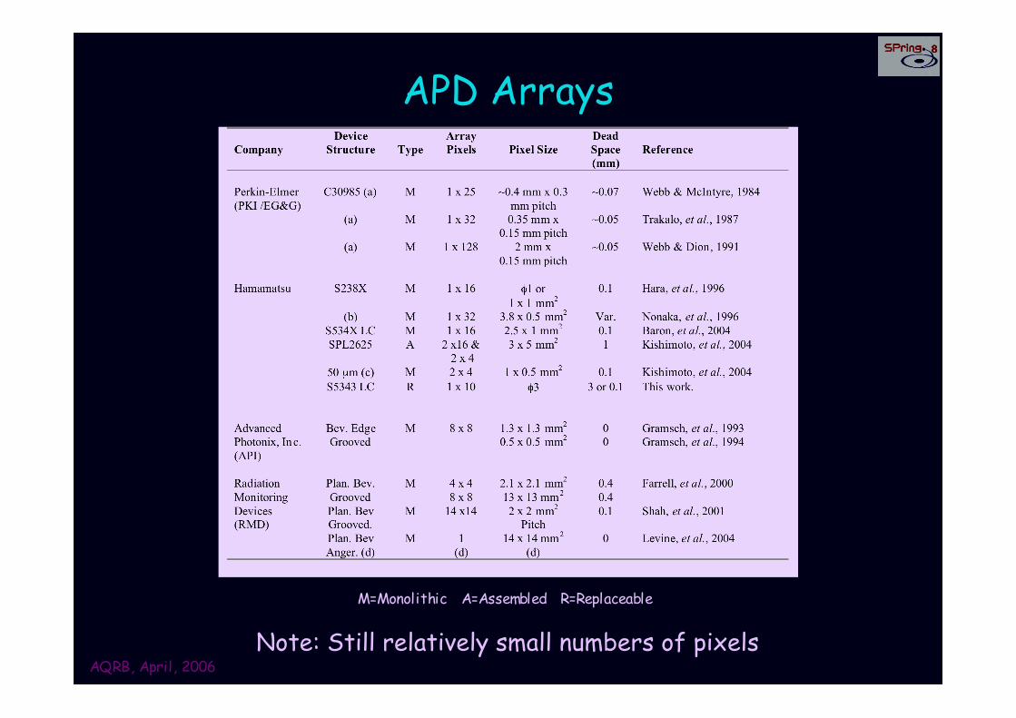
APD Arrays
Note: Still relatively small numbers of pixels
M=Monolithic A=Assembled R=Replaceable
AQRB, April, 2006
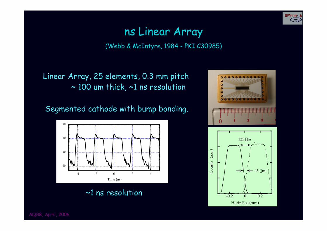
ns Linear Array(Webb & McIntyre, 1984 - PKI C30985)
-0.2 0 0.2Horiz Pos (mm)
45 mm
125 mm
Coun
ts (
a.u.
)
Segmented cathode with bump bonding.
Linear Array, 25 elements, 0.3 mm pitch~ 100 um thick, ~1 ns resolution
101
102
103
104
-4 -2 0 2 4Time (ns)
~1 ns resolution
AQRB, April, 2006
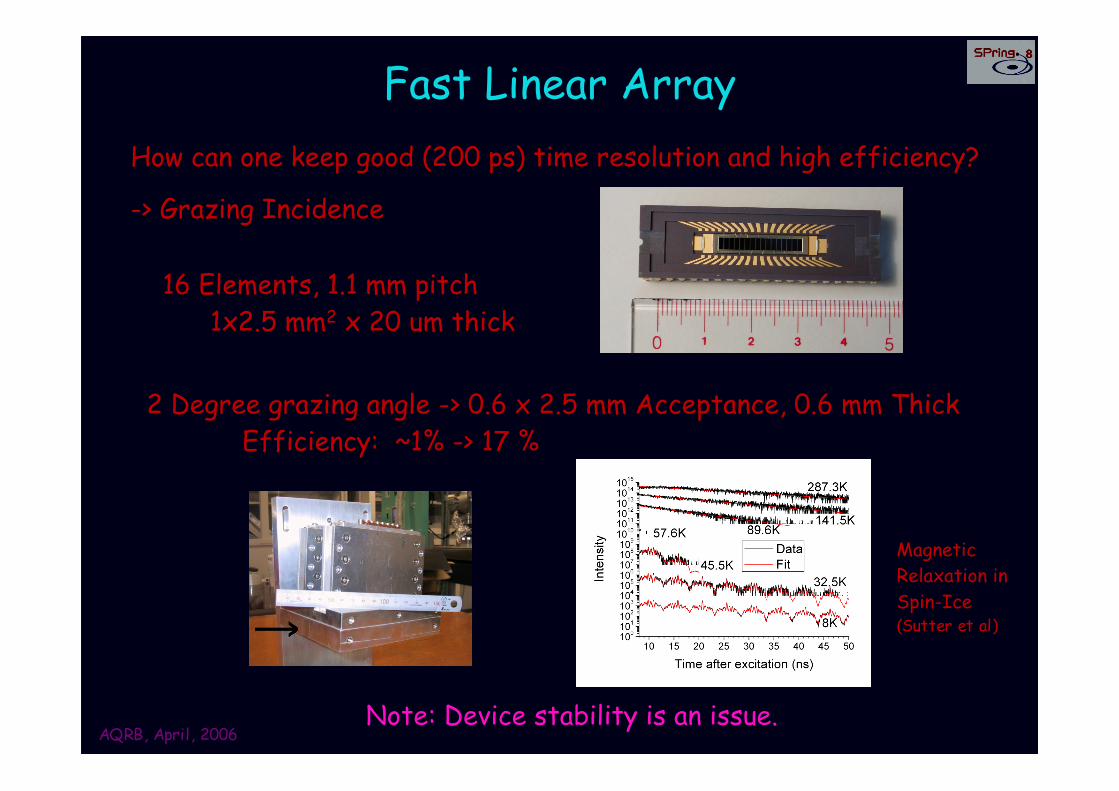
Fast Linear ArrayHow can one keep good (200 ps) time resolution and high efficiency?
-> Grazing Incidence
16 Elements, 1.1 mm pitch 1x2.5 mm2 x 20 um thick
2 Degree grazing angle -> 0.6 x 2.5 mm Acceptance, 0.6 mm ThickEfficiency: ~1% -> 17 %
MagneticRelaxation in Spin-Ice(Sutter et al)
Note: Device stability is an issue.
AQRB, April, 2006
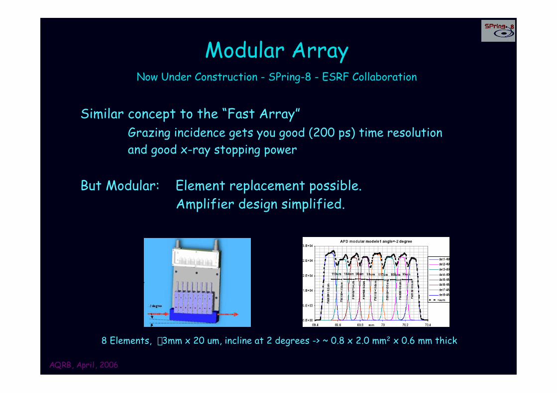
Modular ArrayNow Under Construction - SPring-8 - ESRF Collaboration
Similar concept to the “Fast Array”Grazing incidence gets you good (200 ps) time resolutionand good x-ray stopping power
But Modular: Element replacement possible.Amplifier design simplified.
8 Elements, f3mm x 20 um, incline at 2 degrees -> ~ 0.8 x 2.0 mm2 x 0.6 mm thick
AQRB, April, 2006
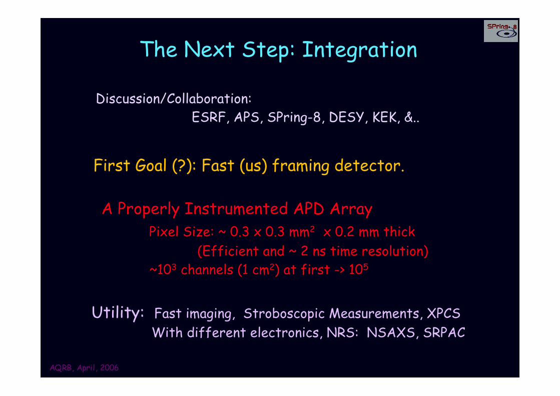
The Next Step: Integration
A Properly Instrumented APD ArrayPixel Size: ~ 0.3 x 0.3 mm2 x 0.2 mm thick
(Efficient and ~ 2 ns time resolution)~103 channels (1 cm2) at first -> 105
First Goal (?): Fast (us) framing detector.
Utility: Fast imaging, Stroboscopic Measurements, XPCS With different electronics, NRS: NSAXS, SRPAC
Discussion/Collaboration: ESRF, APS, SPring-8, DESY, KEK, &..
AQRB, April, 2006
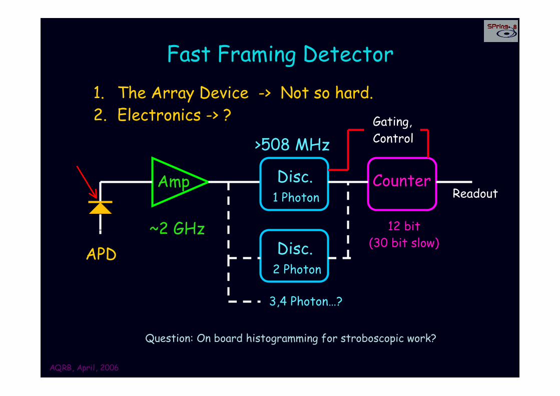
Fast Framing Detector1. The Array Device -> Not so hard.2. Electronics -> ?
APD~2 GHz
1 PhotonAmp
>508 MHz
CounterDisc.
2 PhotonDisc.
3,4 Photon…?
12 bit(30 bit slow)
Question: On board histogramming for stroboscopic work?
Gating,Control
Readout
AQRB, April, 2006
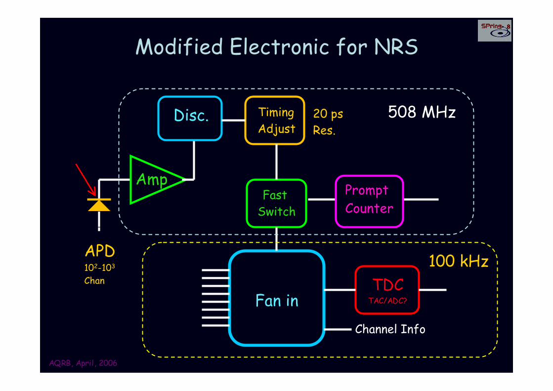
Modified Electronic for NRS
APD102-103
Chan
AmpPromptCounter
Disc. TimingAdjust
20 ps Res.
Fast Switch
Fan inTDC
TAC/ADC?
508 MHz
100 kHz
Channel Info
AQRB, April, 2006
APD Collaborators
KEK: S. Kishimoto
ESRF: T. Deschaux, R. Rüffer
SPring-8: T. Ishikawa (& T. Kudo)
AQRB, April, 2006
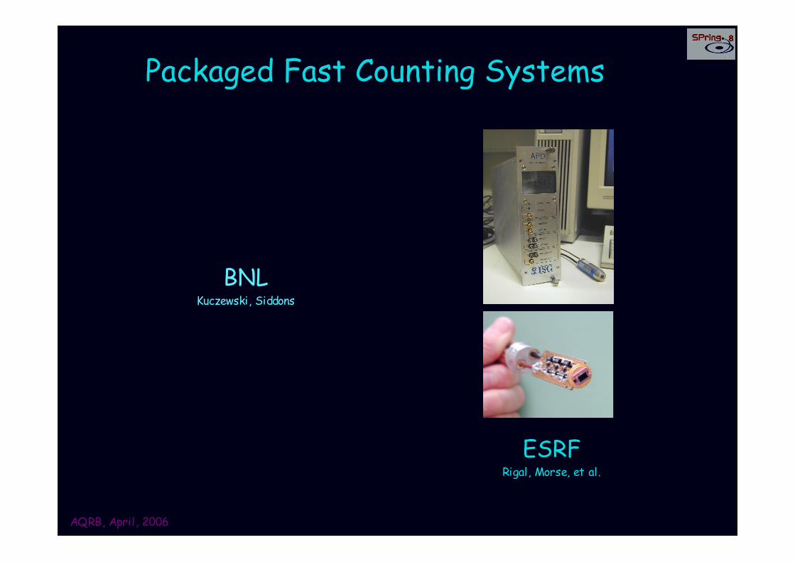
Packaged Fast Counting Systems
ESRFRigal, Morse, et al.
BNLKuczewski, Siddons