Embed Size (px)
Citation preview
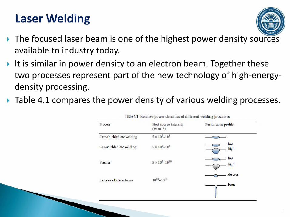
The focused laser beam is one of the highest power density sources available to industry today.
It is similar in power density to an electron beam. Together these two processes represent part of the new technology of high-energy-density processing.
Table 4.1 compares the power density of various welding processes.
1
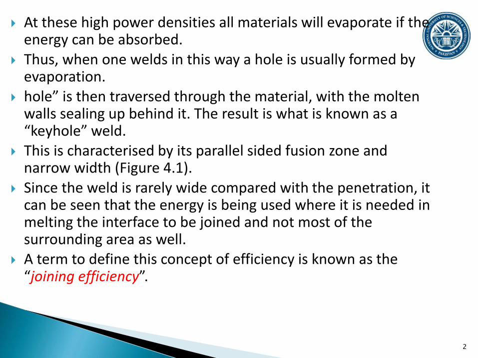
At these high power densities all materials will evaporate if the energy can be absorbed.
Thus, when one welds in this way a hole is usually formed by evaporation.
hole” is then traversed through the material, with the molten walls sealing up behind it. The result is what is known as a “keyhole” weld.
This is characterised by its parallel sided fusion zone and narrow width (Figure 4.1).
Since the weld is rarely wide compared with the penetration, it can be seen that the energy is being used where it is needed in melting the interface to be joined and not most of the surrounding area as well.
A term to define this concept of efficiency is known as the “joining efficiency”.
2

3

It is defined as Vt/P where V is the traverse speed (mm s−1), t is the thickness welded (mm) and P is the incident power (kW).
4
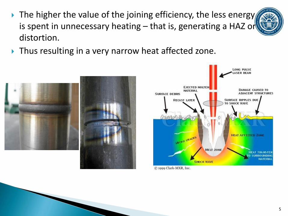
The higher the value of the joining efficiency, the less energy is spent in unnecessary heating – that is, generating a HAZ or distortion.
Thus resulting in a very narrow heat affected zone.
5
6
7

8

Please go through the following text titled “laser welding literature review” uploaded on LMS.
9
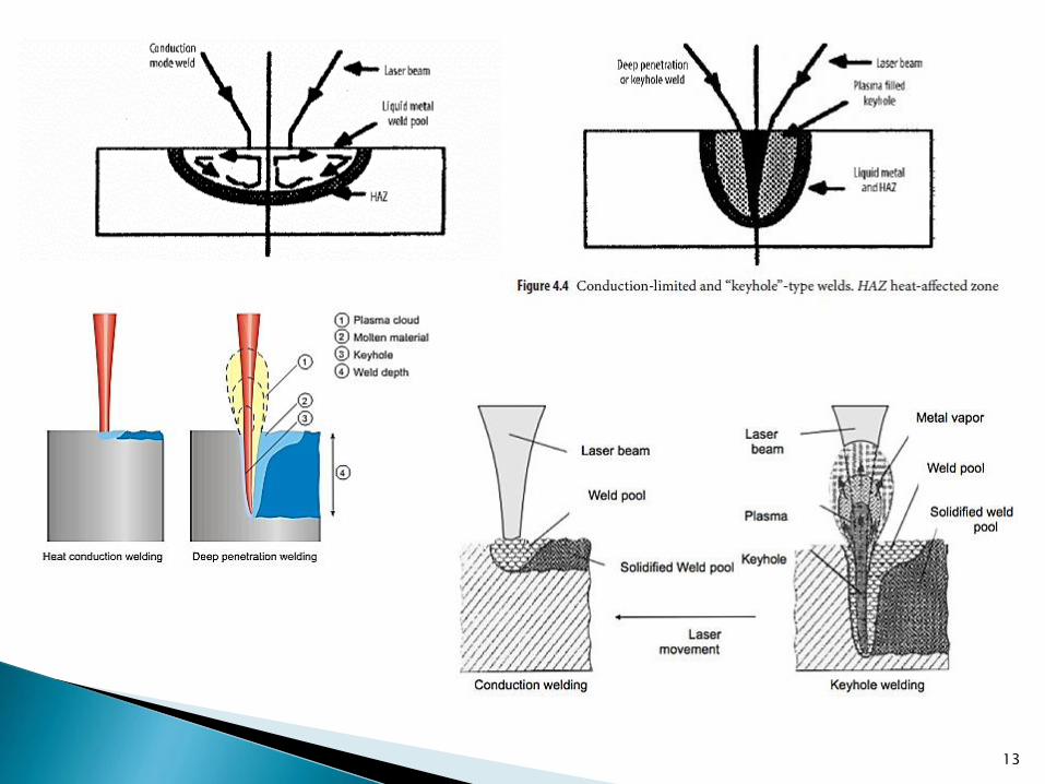
There are two modes of welding with the laser illustrated in Figure 4.4.
Conduction limited welding occurs when the power density at a given welding speed is insufficient to cause boiling and therefore to generate a keyhole.
The weld pool has strong stirring forces driven by Marangoni-type forces resulting from the variation in surface tension with temperature.
Most surface treatments in which melting occurs employ an out-of-focus beam, which results in conduction-limited weld beads.
10

The alternative mode is “keyhole” welding, in which there is sufficient energy per unit length to cause evaporation and hence a hole in the melt pool.
This hole is stabilised by the pressure from the vapour being generated.
In some high-powered plasma welds there is an apparent hole, but this is mainly due to gas pressures from the plasma or cathode jet
The “keyhole” behaves like an optical black body in that the radiation enters the hole and is subject to multiple reflections before being able to escape rather than from evaporation. In consequence, nearly all the beam is absorbed.
11

This can be both a blessing and a nuisance when welding higher reflectivity materials,
since much power is needed to start the “keyhole”, but as soon as it has started then the absorptivity jumps from 3 to 98% with possible damage to the weld structure.
There are two principal areas of interest in the mechanism of keyhole welding.
The first is the flow structure since this directly affects the wave formation on the weld pool and hence the final frozen weld bead geometry. This geometry is a measure of weld quality.
The second is the mechanism for absorption within the keyhole which may affect both this flow stability and entrapped porosity
12
13
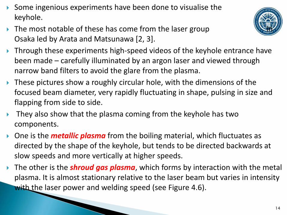
Some ingenious experiments have been done to visualise the keyhole.
The most notable of these has come from the laser group in Osaka led by Arata and Matsunawa [2, 3].
Through these experiments high-speed videos of the keyhole entrance have been made – carefully illuminated by an argon laser and viewed through narrow band filters to avoid the glare from the plasma.
These pictures show a roughly circular hole, with the dimensions of the focused beam diameter, very rapidly fluctuating in shape, pulsing in size and flapping from side to side.
They also show that the plasma coming from the keyhole has two components.
One is the metallic plasma from the boiling material, which fluctuates as directed by the shape of the keyhole, but tends to be directed backwards at slow speeds and more vertically at higher speeds.
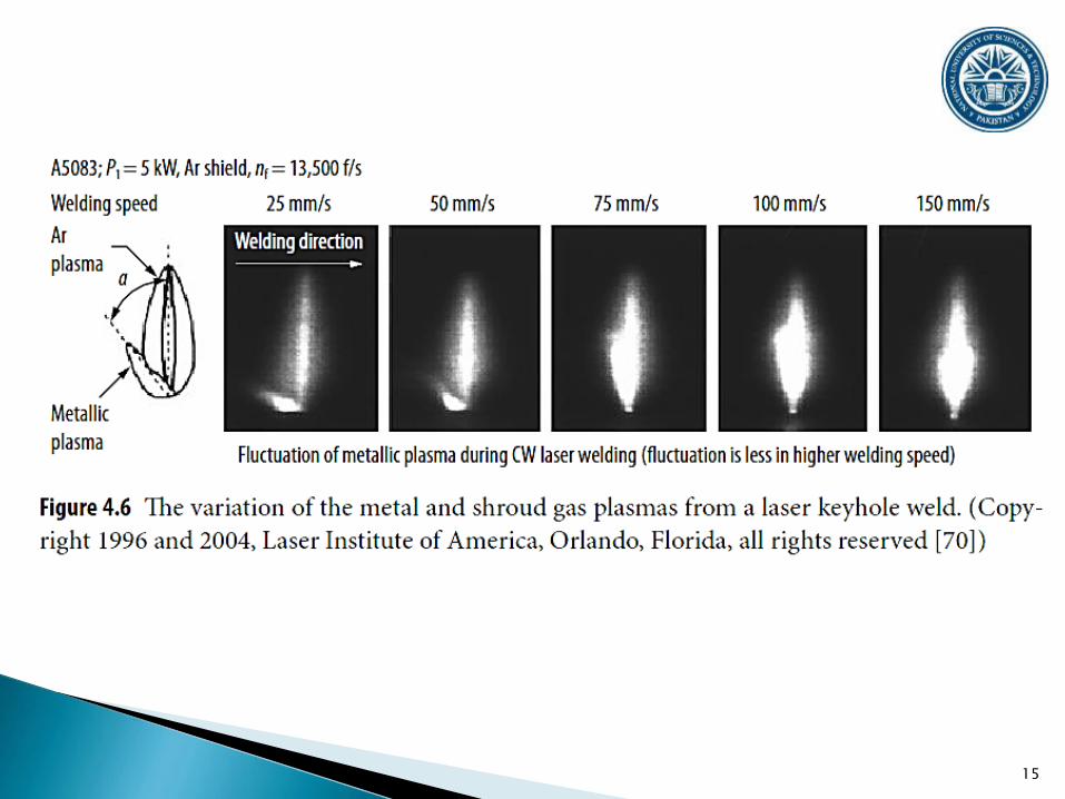
The other is the shroud gas plasma, which forms by interaction with the metal plasma. It is almost stationary relative to the laser beam but varies in intensity with the laser power and welding speed (see Figure 4.6).
14
15

16

17

The vapour in the keyhole consists of very hot vapour from the material being welded together with shroud gas that has been sucked in owing to the pulsation of the keyhole.
This vapour may be sufficiently hot to be partially ionised, forming a charged plasma.
The flow of vapour out of the keyhole is fast, approaching sonic speeds, and hence it makes a snarling noise.
This flow through the neck at the throat of the keyhole would be expected to show Helmholtz instabilities (similar to a flag flapping), with the higher velocities in the throat creating a low-pressure zone that would tend to close the throat.
This may be one of the causes of the fluctuation noted, the other being the rapid fluctuation in fluid flow around the keyhole, driven by surface tension variations and sporadic boiling within the keyhole.
18
The boiling reaction is very vigorous and causes a spray to form. This emerges as particles and dust.
The temperature of the emerging vapour has been measured by Greses et al. [4] using a spectrographic technique.
They showed that for Nd:YAG laser welding the vapour is not ionised and is only at a temperature of the order of 2,000 ○C, whereas for CO2 laser welding the vapour is ionised and is much hotter, at around 6,000–10,000 ○C.
The implication of these temperatures is that the composition of the shroud gas does not matter when welding with a Nd:YAG laser as much as it does with a CO2 laser.
This implication was confirmed experimentally by Greses et al. [4]. The charge in the CO2 is confirmed by the standing electric field
around the plasma.However, the plasma or hot vapour in both cases
interferes with the beam delivery. Figure 4.11 illustrates what can happen if there is no shroud gas to
blow the plasma away when welding with 10 kW of CO2 laser power.
19

This blocking action can be caused either by absorbing the beam by inverse bremsstrahlung with the free electrons and re-radiating or
by scattering in the particulate material being ejected or
defocusing the beam in the steep refractive index gradients resulting from the steep thermal gradients in the gas.
20

The main process parameters are illustrated in Figure 4.12. They are as follows:
Beam properties; power, pulsed or continuous; spot size and mode; polarisation; wavelength.
Transport properties: speed; focal position; joint geometries; gap tolerance.
Shroud gas properties: composition; shroud design; pressure/velocity.
Material properties: composition; surface condition.
21
The main material problems with laser welding, in common with most welding methods, are crack sensitivity, porosity, HAZ embrittlementand poor absorption of the radiation.
For welds of dissimilar metals there is the additional problem of the possible formation of brittle intermetallics.
Cracking is due to the shrinkage stress building up before the
weld has fully solidified and is strong enough to take the stress.
It is thus most likely in metal alloys having a wide temperature range over which solidification occurs, e.g., those with high carbon, sulphur and phosphorous contents.
It is due to the shrinkage stress building up before the
weld has fully solidified and is strong enough to take the stress.
It is thus most likely in metal alloys having a wide temperature range over which solidification occurs, e.g., those with high carbon, sulphur and phosphorous contents.
22
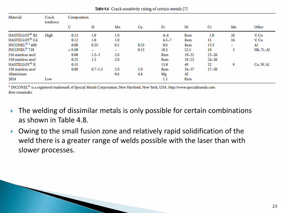
The welding of dissimilar metals is only possible for certain combinations as shown in Table 4.8.
Owing to the small fusion zone and relatively rapid solidification of the weld there is a greater range of welds possible with the laser than with slower processes.
23

24

Pores in the weld pool are produced by the keyhole collapsing too quickly and not allowing the molten metal to flow into the centre of the keyhole before solidification takes place.
They occur primarily in the root of the weld.
Instability of the keyhole formation has been shown to be the main cause of macro-porosity (holes >0.2mm in size) in some Al alloys.
When using pulsed lasers, the porosity tends to increase with increasing power density and pulse time.
25
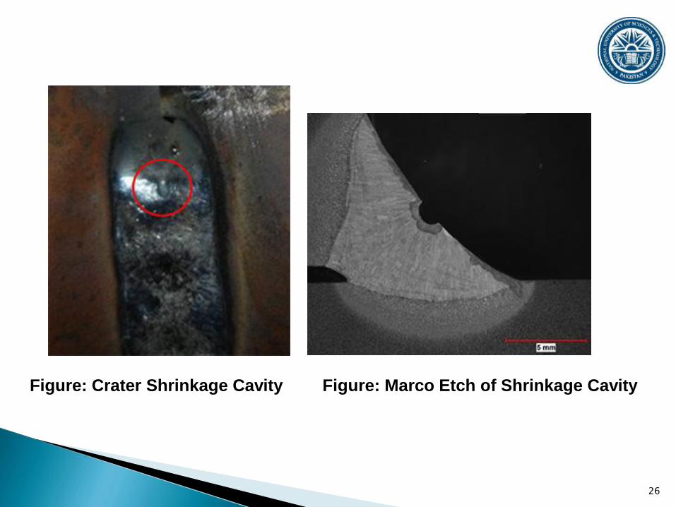
Cratering: when using pulsed lasers, the transition from conduction to keyhole welding is accompanied by more frequent occurrence of both occluded gas pores in the root and cratering of the top surface, particularly at higher power densities.
In general, increasing the power density and pulse time results in a rapid increase in cratering.
26
Figure: Crater Shrinkage Cavity Figure: Marco Etch of Shrinkage Cavity
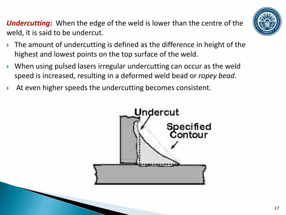
Undercutting: When the edge of the weld is lower than the centre of the weld, it is said to be undercut.
The amount of undercutting is defined as the difference in height of the highest and lowest points on the top surface of the weld.
When using pulsed lasers irregular undercutting can occur as the weld speed is increased, resulting in a deformed weld bead or ropey bead.
At even higher speeds the undercutting becomes consistent.
27
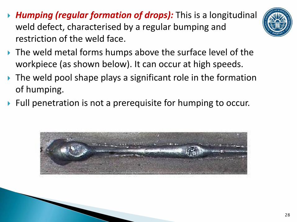
Humping (regular formation of drops): This is a longitudinal weld defect, characterised by a regular bumping and restriction of the weld face.
The weld metal forms humps above the surface level of the workpiece (as shown below). It can occur at high speeds.
The weld pool shape plays a significant role in the formation of humping.
Full penetration is not a prerequisite for humping to occur.
28
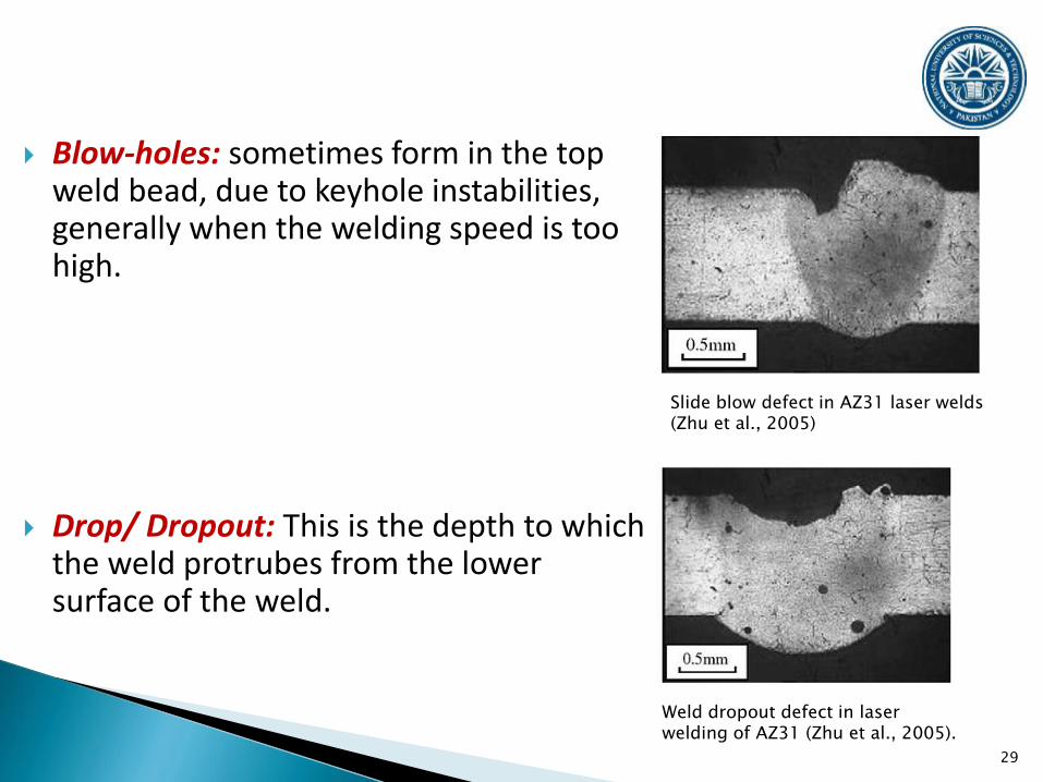
Blow-holes: sometimes form in the top weld bead, due to keyhole instabilities, generally when the welding speed is too high.
Drop/ Dropout: This is the depth to which the weld protrubes from the lower surface of the weld.
29
Slide blow defect in AZ31 laser welds (Zhu et al., 2005)
Weld dropout defect in laser welding of AZ31 (Zhu et al., 2005).

30
Cracking: have been observed to formed mainly in the upper part of weldments.

Non-uniformity and surface roughness
The surface roughness (on a micron scale) along the centreline of the top weld surface has been shown to be affected by welding speed, laser power, pulse duration and average peak power density of a pulsed laser.
Plots of roughness versus welding speed showed a minimum in the roughness at an optimum welding speed.
As laser power was increased the sensitivity of the weld bead roughness to welding speed became less pronounced, and the size of roughness was generally lower.
At too low a laser power the roughness increased rapidly, which is due to the thermodynamic instabilities in the weld pool.
Increasing pulse duration increased weld roughness and reduced the range of acceptable welding speeds.
31

Alloy loss and changes in chemical composition
Vaporisation of the material with preferential loss of the lower melting temperature elements can occur at high energy inputs.
This will cause loss of alloying element and change of composition at different location within the weld bead resulting in undesirable properties.
The welding speed has been found to have little effect on weld composition provided a stable keyhole had formed, showing that alloy loss is minimised once a stable keyhole is produced.
32
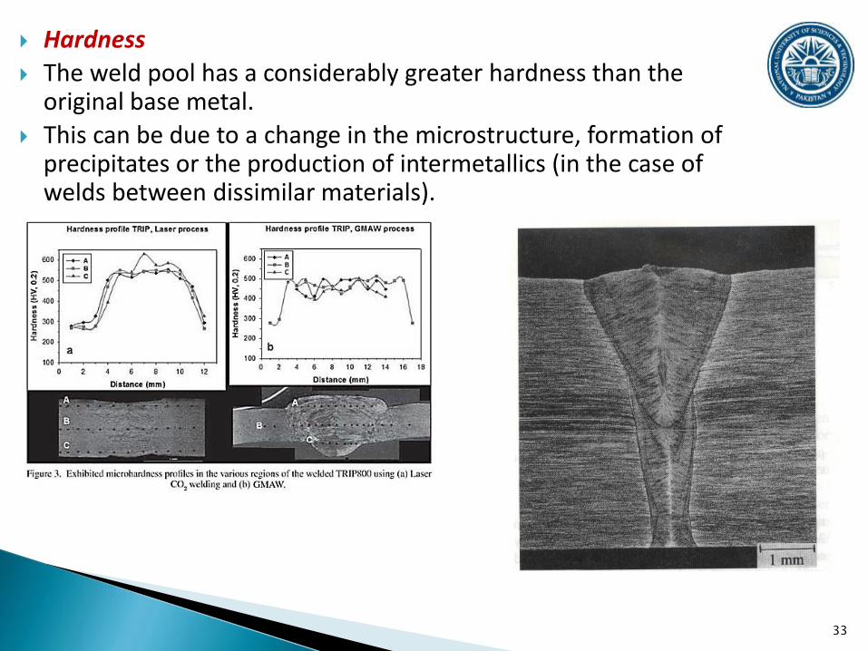
Hardness
The weld pool has a considerably greater hardness than the original base metal.
This can be due to a change in the microstructure, formation of precipitates or the production of intermetallics (in the case of welds between dissimilar materials).
33

A heat-affected zone (HAZ) is the portion of the base metal that was not melted during brazing and cutting/welding, but whose microstructure and mechanical properties were altered by the heat.
This alteration can be detrimental, causing stresses that reduce the strength of the base material, leading to catastrophic failures.
The HAZ occurs inside the metal and cannot be seen.
Preferential corrosion of a heat-affected zone is a widely known phenomenon.
High-temperature exposure and welding can significantly affect the microstructure and properties of the heat-affected zone that makes them more susceptible to corrosion.
The microstructural changes that occur in heat-affected zones include carbide precipitation and intermetallic phase formation.
34

Heat affected zones can be of varying size and strength. The extent and magnitude of the HAZ is inversely proportional to
the thermal diffusivity and cooling rates of the material:◦ Where thermal diffusivity is high, the material cooling rate is high
and the HAZ is small.◦ Where thermal diffusivity is low, the cooling rate is slower and the
HAZ is larger. The extent and magnitude of property change depends primarily
on:◦ Base material◦ Weld filler metal◦ Amount and concentration of heat input by the welding process
The width of the HAZ is influenced by:◦ Cut speed - In general, faster speeds result in a smaller HAZ.◦ Amperage (when using plasma) - For a given thickness of metal, a
higher amperage (and consequently a faster cut speed) results in a smaller HAZ.
◦ Type of metal being cut - Increased temperatures and longer cutting times will result in a wider HAZ.
35
All thermal cutting processes create a heat-affected zone in the cut metal.
The amount of heat inputted by the welding process plays an important role:
◦ Oxyfuel welding uses high heat input and increases the size of the HAZ.
◦ Laser and electron-beam welding give a highly concentrated, limited amount of heat, resulting in a small HAZ.
◦ Arc welding falls between these two extremes.
The heat from the welding process and subsequent re-cooling causes change from the weld interface to the termination of the sensitizing temperature in the base metal.
These changes can be minimized by following proper welding procedures and using low-carbon stainless steel alloys.
36
37
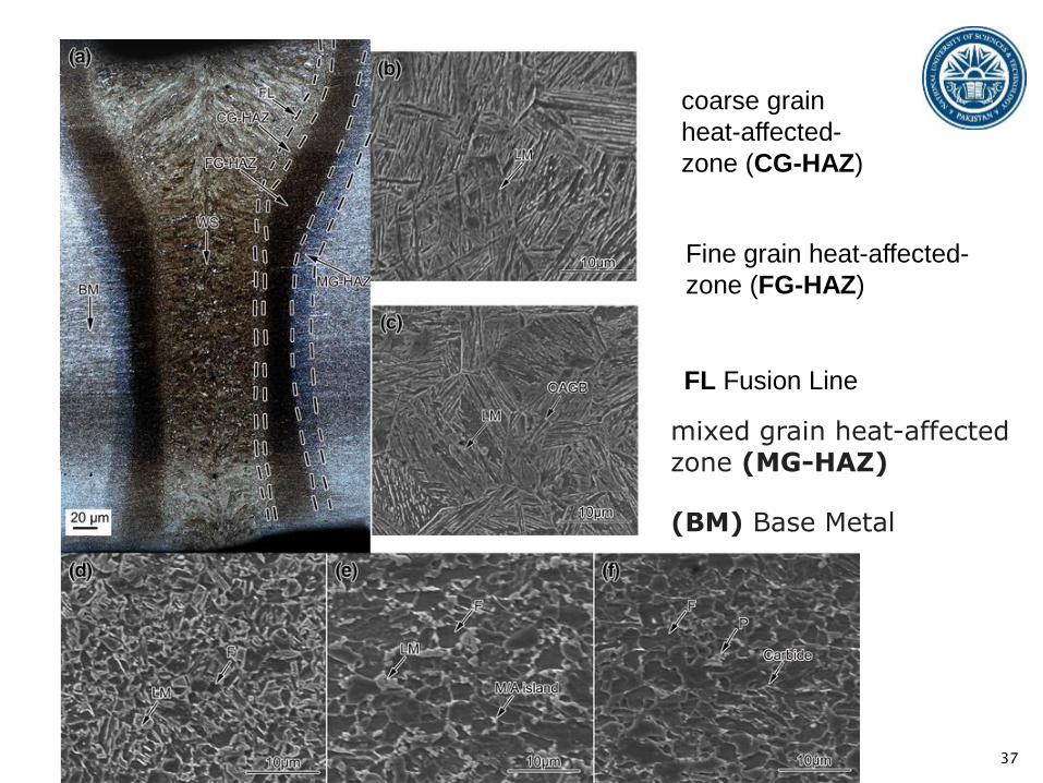
coarse grain
heat-affected-
zone (CG-HAZ)
Fine grain heat-affected-
zone (FG-HAZ)
FL Fusion Line
mixed grain heat-affected zone (MG-HAZ)
(BM) Base Metal

38