Embed Size (px)
Citation preview
YCAS
AIR COOLEDSCREW CHILLER
R407C REFRIGERANT
COOLING CAPACITIES260 kW to 1194 kW
The YCAS range of chillers are designedfor water or water-glycol cooling. Modelsare available with 2, 3 and 4 refrigerantcircuits.
Semi-hermetic twin helical screwcompressors are provided to ensure highoperational efficiencies and reliableperformance.
Optional heat recovery condensers ordesuperheaters are available on 2 and 4refrigerant circuit models
All units are designed to be locatedoutside on the roof of a building or atground level.
CONTENTSSpecification
Accessories and Options
Refrigeration Flow Diagrams
Operating Limitations
Selection Guide
Cooling Capacities
Heat Recovery Capacities
Physical Data
Electrical Data
Connection Diagrams
Clearances
Dimensions
AVAILABLE MODELS & NOMINAL COOLING CAPACITIES TABLE 1
FEATURES BENEFITSManufactured to ISO 9001 EN 29001. High standard of quality control.
Two, three and four refrigerant circuits. System stand-by security.
Constructed from heavy gauge painted galvanised steel. Durable and weather protected.
High efficiency industrial type semi-hermetic twin helicalscrew compressor.
Energy efficient, long life reliable compressor.
Full factory run test. Operating quality control.
Optional acoustic kit. Reduces operating sound levels.
Optional Star/Delta compressor starter. Reduced starting current.
Separate power and control compartments with lockabledoors and emergency stop device.
Operator safety considerations.
Power compartment optional door interlocked isolators. Operator safety convenience.
Microprocessor control with visual display of temperatures,pressures, motor currents, operating hours and number ofstarts.
System data logging and temperature resetcapability. Fault diagnostics. Energymanagement.
Unit remote alarm contacts. Warning notification.
Remote water temperature reset. Improved operating efficiency.
Building management system interface. For central data logging and single point fullsystem monitoring and control.
Fuzzy logic. Maximise capacity control.
Suction line heat exchanger and counter flow cooler. Maximises chiller capacity and efficiency.
Page H.13Doc. No. PC102/11.01/GB
YC
AS
eco²A
IRC
OO
LE
DS
CR
EW
CH
ILL
ER
Model 0295 0335 0375 0425 0475 0515 0555 0575 0605
Refrigerant CircuitsCooling (kW) 260 308 364 397 446 495 527 558 584Heat Recovery (kW) 253 306 365 383 435 488 527 566 574DeSuperheater (kW) 22 26 32 33 38 42 46 49 50
Model 0685 0775 0835 0905 0965 1065 1135 1215Refrigerant CircuitsCooling (kW) 692 782 829 898 923 1056 1125 1194Heat Recovery (kW) 1020 1100 1182DeSuperheater (kW) 82 87 100
Cooling capacities at 7°C leaving chilled liquid temperature and 35°C ambientair temperature.Optional heat recovery capacities at 40°C leaving hot liquid temperatureand 7°C leaving chilled liquid temperature.Optional Desuperheater capacities at 60°C leaving hot liquid temperature,7°C leaving chilled liquid temperature and 35°C ambient air temperature.
Not Available
Two
Three Four
Not Available
0
5
25
75
95
100
0
5
25
75
95
100
0
5
25
75
95
100
0
5
25
75
95
100

SPECIFICATIONThe YCAS Air Cooled chiller shall becompletely assembled with allinterconnecting refrigerant piping andinternal wiring, ready for field installation.The unit shall be pressure tested,evacuated, and fully factory charged withrefrigerant and oil in each of theindependent refrigerant circuits.
After assembly, an operational test shallbe performed with water flowing throughthe cooler to ensure that each refrigerantcircuit operates correctly.
The unit structure shall be manufacturedfrom heavy gauge, galvanised steel andcoated with baked-on powder paint(Desert Sand (RAL 1019)). This providesa finish which, when subjected to 500hour, 5% salt spray conditions, showsbreakdown of less than 3mm either sideof a scribed line.
All exposed power wiring shall be routedthrough liquid-tight, non-metallic conduit.
CompressorsEach compressor shall be direct drive,semi-hermetic, rotary twin screw type andinclude the following items:
• Two screw rotors, with asymmetricprofiles, manufactured from forgedsteel.
• A cast iron compressor housingprecision machined to provide optimalclearance for the rotors.
• The entire compressor, from suction todischarge shall have a design workingpressure of 31 bar.
• Capacity Control: The compressorsshall start at the minimum load positionand provide a capacity control rangefrom 100% to 10% of the full chiller loadusing a continuous function slide valve.A microprocessor controlled outputpressure regulating capacity controlvalve shall be supplied to commandcompressor capacity independent ofcontrol valve input pressure and tobalance the compressor capacity withthe cooling load.
• An automatic spring return of capacitycontrol valve to the minimum loadposition to ensure compressor startingat minimum motor load.
• An internal discharge check valve toprevent rotor backspin upon shutdown.
• An acoustically tuned, internaldischarge muffler to minimise noise atthe source, while optimising flow formaximum performance.
• Discharge and suction shut-off servicevalves.
• A rain tight terminal box.• A reliable suction gas cooled high
efficiency, accessible hermetic motorwith redundant overload protectionusing both thermistor and currentoverload protection.
• A suction gas screen and serviceable,0.5 micron full flow oil filter within thecompressor housing.
• A 350 W compressor body heater.
Oil SeparatorOil separators with a design workingpressure of 31 bar shall be the highefficiency, augmented gas impingementtype to maximise oil extraction withoutfragile media to break down.
Oil CoolerOil cooling shall be provided by adedicated air-cooled finned tube typeheat exchanger located in the condensersection of the unit.
Refrigerant CircuitsAn independent refrigerant circuit shall beprovided per compressor. Each circuit willuse copper refrigerant pipe formed oncomputer controlled bending machines toreduce the number of brazed jointsresulting in a reliable and leak resistantsystem.
Liquid line components shall include:manual shut-off valve with charging port,high absorption removable corefilter-drier, solenoid valve, sight glass withmoisture indicator, and thermostaticexpansion valves.
Suction lines shall be covered withclosed-cell insulation.
CoolerThe cooler shall be a special optimised'Counter-Flow' heat exchanger, which willtake advantage of the "Glide"characteristic of R407C. It will employtechnologically advanced (patentpending) high efficiency tube assemblieswhich make possible a single refrigerantpass, delivering refrigerant suction gaswarmer than the leaving chilled water atfull load. An independent circuit shall beprovided for each compressor. The shelldesign working pressure shall be 10.3bar, and 23.8 bar for the tubes.
The cooler shall have water bafflesfabricated from galvanised steel to resistcorrosion, removable heads for access tointernally enhanced, seamless, coppertubes. The water nozzles shall beprovided with grooves for mechanicalcouplings and be insulated by thecontractor after pipe installation. Watervent and drain connections shall also beincluded.
The cooler shall be equipped with athermostatically controlled heater forprotection to -29°C ambient and insulatedwith 19 mm flexible closed-cell foam.
Suction Line Heat ExchangerEach refrigerant circuit utilises arefrigerant to refrigerant, compact, shelland tube type suction line heat exchangerto maximise chiller capacity and efficiencyby subcooling liquid refrigerant deliveredto the expansion valve and superheatingsuction gas delivered to the compressor.The design working pressure shall be 31bar. The exchanger shall be constructedin accordance with applicable pressurevessel safety code.
CondenserFans - The fans shall be dynamically andstatically balanced, direct drive withcorrosion resistant glass fibre reinforcedcomposite blades moulded into lowsound, full airfoil cross section, providingvertical air discharge from extendedorifices for efficiency and low sound. Eachfan shall be located in a separatecompartment to prevent cross flow duringfan cycling. Guards of heavy gauge, PVC(polyvinyl chloride) coated galvanisedsteel shall be provided.
Motors - The fan motors shall be the highefficiency, direct drive, 6 pole, 3 phase,Class-“F”, current overload protected,totally enclosed (TEAC) type with doublesealed, permanently lubricated, ballbearings.
Coils - Fin and tube condenser coils shallbe manufactured from seamless,internally enhanced, high condensingcoefficient, corrosion resistant coppertubes arranged in staggered rows andmechanically expanded into corrosionresistant black fin aluminium alloy with fullheight fin collars. The design workingpressure shall be 31 bar and each coilshall be pressure tested to 34 bar.
Power and Control PanelAll controls and motor starting equipmentnecessary for unit operation shall befactory wired and function tested.
The panel enclosure shall be designed toIP55 (rain/dust tight) and bemanufactured from powder paintedgalvanised steel.
The Power and Control Panel shall bedivided into a power section for eachelectrical system, a control section and anelectrical options section.
Power and control sections shall have aseparate hinged, latched, and gasketsealed door equipped with wind struts forsafer servicing.
Each power compartment shall contain:
Compressor and fan starting contactors,fan motor external overloads, controlcircuit serving compressor capacitycontrol, compressor and fan contactorcoils and compressor motor overloads.
Compressor Motor Overloads: Currenttransformers sense each phase, as aninput to the microprocessor, to protectcompressor motors from damage due to:low input current, high input current,unbalanced current, single phasing,phase reversal, and compressor lockedrotor.
Page H.14Doc. No. PC102/11.01/GB
0
5
25
75
95
100
0
5
25
75
95
100
0
5
25
75
95
100
0
5
25
75
95
100
The control section shall contain:
On/Off toggle switch, microcomputerkeypad and display, microprocessorboard, I/O expansion board, relay boardsand power supply board.
The options section shall contain:
A control circuit transformer providing115/1Ø power to the unit control system.
Electrical options as described in“Accessories and Options”.
Microprocessor ControlsFuzzy Logic control will be incorporatedin the YCAS range of chillers. Fuzzy logicallows the control system to monitorseveral key variables to provide tighter,more stable, chilled water temperaturecontrol. The control system monitors theleaving chilled water temperature to trackwhere it has been, where it is now, howfast it is moving, and accurately adjustschiller operation in anticipation ofexpected performance to minimisehunting and save energy.
The microprocessor shall have thefollowing functions and displays:
• A liquid crystal 40 character displaywith text provided on two lines and lightemitting diode backlighting for outdoorviewing.
• A colour coded, 35 button, sealedkeypad with sections for Display, Entry,Setpoints, Clock, Print, Program andUnit On/Off switch.
• The standard controls shall include:brine chilling or thermal storage,automatic pump down, run signalcontacts, demand load limit fromexternal building automation systeminput, remote reset liquid temperaturereset input, unit alarm contacts, chilledliquid pump control, automatic resetafter power failure, automatic systemoptimisation to match operatingconditions, software stored innon-volatile memory (EPROM) toeliminate chiller failure due to ACpower failure.
• Programmed Setpoint shall be retainedin a lithium battery backed RTCmemory for a minimum of 5 years.
DISPLAY – In Metric (°C and Bar) orEnglish (°F and psi) units. For eachcircuit, the following items shall bedisplayed:
• Return and leaving chilled liquid, andambient temperature.
• Day, date and time. Daily start/stoptimes. Holiday and Manual Overridestatus.
• Compressor operating hours andstarts. Automatic or manual lead/lag.Lead compressor identification.
• Run permissive status. No cooling loadcondition. Compressor run status.
• Anti-recycle timer and anti-coincidentstart timer status per compressor.
• System suction (and suctionsuperheat), discharge, and oilpressures and temperatures.
• Percent full load compressor motorcurrent. Compressor capacity controlvalve input steps.
• Cut-out status and set-points for:supply fluid temperature, low suctionpressure, high discharge pressure andtemperature, high oil temperature, lowand high ambient, high and low current,and low leaving liquid temperature.
• Unloading limit setpoints for highdischarge pressure and compressormotor current.
• Liquid pull-down rate sensitivity (0.3°Cto 3°C/minute in 0.05°C increments).
• Status of: evaporator heater,condenser fans, load and unloadtimers, chilled liquid pump.
• “Out of range” message.• Up to 6 fault shut down conditions.• Standard Display Language is English,
with other language options.ENTRY – Enter set point changes, cancelinputs, advance day, and change AM/PM.
SET POINTS – Chilled liquidtemperature, chilled liquid range, remotereset temperature range.
CLOCK – Time, daily or holiday start/stopschedule, manual override for servicing.
PRINT – Operating data or system faultshutdown history for last six faults, andsoftware version. Printouts through anRS-232 port via a separate printer (byothers).
PROGRAM – Low leaving liquidtemperature cutout, 300 to 600 secondanti-recycle timer, lag compressor starttime delay, average motor current unloadpoint, liquid temperature set-point resetsignal from YORK ISN or buildingautomation system (by others) via:
• Pulse width modulated (PWM) input forup to 22°C total reset as standard.
• Optional Building Automation Systeminterface input card for up to 11°C resetusing a 4 to 20 mA, 0 to 10 Vdc input, ordiscrete reset input.
• [NOTE: The Standard microprocessorcan be directly connected to a YORKISN Building Automation System viathe standard on-board RS485communication port. This Option alsoprovides open system compatibilitywith other communications networks(BACNET™ & LONMARK™) viainterface through standard onboard485 or 232 port and an externalYorkTalk Translator.]
• Additional functions (passwordprotected) for programming by aqualified service technician:
• Cut-outs for low and high ambient, lowsuction pressure, high dischargepressure, high oil temperature.
• Refrigerant type.• High discharge pressure unload
setpoint.• Fan control discharge pressure set
point.• Fan ON/OFF pressure differential.• Compressor motor current percent
limit.• The Standard unit controls permit
operation down to -18°C outdoorsambient temperature.
Motor ProtectionThe microprocessor motor protectionprovides high current protection to ensurethat the motor is not damaged due tovoltage, excess refrigerant or otherproblems that could cause excessivemotor current.
The microprocessor also provides lowmotor current protection when it senses amotor current of less than 10% FLA.
A motor protector module providesthermal and current motor overloadprotection. The module also protectsagainst phase to phase currentimbalance, over current, under currentand phase rotation.
Page H.15Doc. No. PC102/11.01/GB
0
5
25
75
95
100
0
5
25
75
95
100
0
5
25
75
95
100
0
5
25
75
95
100

ACCESSORIES AND OPTIONSELECTRICAL OPTIONSPower Supply Connection Options
Multi Point Power Supply Connection:Two field provided 400 V, 3Ø, 50 Hzsupplies to the unit with circuit protection.
Single Point Power Supply Connection:One field provided 400 V, 3Ø, 50 Hzsupply to the unit with circuit protection.
Power Factor CorrectionFactory mounted passive (static)correction capacitors to correct unitcompressor power factors to 0.95(depending on operating conditions).
Star-Delta Compressor Motor StarterProvides approximately 65% reducedinrush current compared to direct on-linestarting (Factory Mounted).
Closed Transition Star/Delta StartWith the addition of closed transitioncontactors and resistors the change overspike during starting can be reduced tonearer the star inrush level thus reducingthe risk of electrical interference duringcompressor start.
OptiView™ Control panelField mounted remote control panel, usedto monitor and control remote York aircooled chillers from an indoor location.Each panel can control up to 8 chillers.
Remote Control Panel and Wall AdaptorField mounted remote control panel.(Cannot be fitted when a (BAS) Interfaceor Multi-unit Sequence Control is fitted).
Multi-unit Sequence ControlA factory mounted Sequencing ControlCentre to manage sequencing control ofup to eight chillers in parallel based onmixed liquid temperature (interconnectingwiring by others).(Cannot be fitted when a (BAS) Interfaceor Remote Control Panel is fitted).
Building Automation System (BAS)InterfaceProvides a means to reset the leavingchilled liquid temperature and/or percentfull load amps (current limiting) from theBAS (Factory Mounted):
Printed circuit board to accept 4 to 20 mA,0 to 10 Vdc, or dry contact closure inputfrom the BAS.(Cannot be fitted when a Multi-unitSequence Control or Remote ControlPanel is fitted).
Note: A YORK ISN Building AutomationSystem can provide a Pulse WidthModulated (PWM) signal direct to thestandard control panel via the standardon-board RS485 port.
Flow Switch AccessoryJohnson Controls model F61MG-1CVapour-proof SPDT, NEMA 4X switch,10.3 bar DWP, -29°C to 121°C, with1" NPT (IPS) connection for uprightmounting in horizontal pipe. A flow switchmust be field installed with each unit.
High Static Pressure FansFans and motors suitable for highexternal static conditions to 150 Pa.
OTHER OPTIONSHeat Recovery(2 and 4 Refrigerant Circuit Models only)Factory fitted plate heat exchanger(s) toprovide warm water during cooling tosatisfy heating and domestic hot waterrequirements.
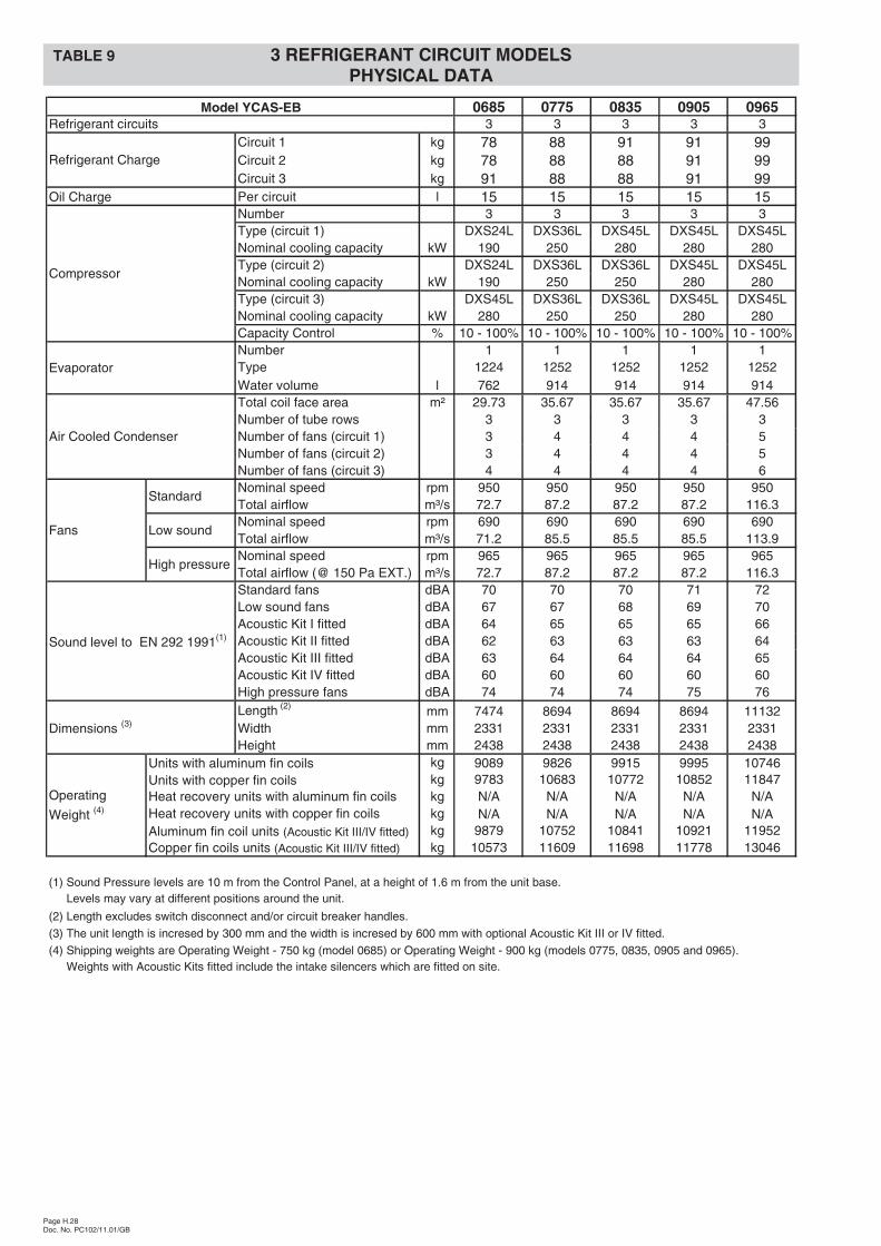
Desuperheaters(2 and 4 Refrigerant Circuit Models only)Factory fitted desuperheaters on comp-ressor discharge lines to provide hotwater during cooling.
Alternative Condenser Coils:Copper fin condenser coils – Con-denser coils are constructed withcorrosion resistant copper fins.
Blygold Protective Coating - is recom-mended for corrosive applications, suchas coastal locations where salt spray mayhit the condenser fins.
Un-coated aluminium fin stock isavailable as an option.
DX Cooler Options:21 Bar Waterside Design WorkingPressure – The DX cooler waterside isdesigned and constructed for 21 barworking pressure. (Factory Mounted)
Flange Accessory – Consists of raisedface flanges to convert grooved waternozzles to flanged cooler connections.Includes companion flanges for fieldmounting.
Unit EnclosuresWired guards – Heavy gauge weldedwire mesh guards mounted over theexterior condenser coil faces and aroundthe bottom of the unit (factory mounted).
Sound Reduction OptionsLow sound fans – Reduced RPM fanmotors and alternative fan selection forlow sound applications.
Compressor sound enclosures –Acoustically treated flexible compressorenclosures.
Acoustic Kit I – Comprises low soundfans and compressor sound enclosures.
Acoustic Kit II – Comprises low soundfans, compressor sound enclosures andfan speed inverters.
Acoustic Kit III – Comprises low soundfans, fan baffles and side and end intakesilencers.
Acoustic Kit IV (ELS) – Comprises lowsound fans, fan baffles, side and endintake silencers, compressor soundenclosures and fan speed inverters.
Vibration Isolation25 mm spring isolators – Leveladjustable, spring and cage type isolatorsfor mounting under the unit base rails(Field mounted).
50 mm seismic spring isolators –Restrained Spring-Flex Mountingsincorporate welded steel housing withvertical and horizontal limit stops.Housings designed to withstand aminimum 1.0 g accelerated force in alldirections to 50 mm. Level adjustable,deflection may vary slightly by application(Field mounted).
Page H.16Doc. No. PC102/11.01/GB
Mod
els
Opt
ion
Term
inal
Blo
ckpe
rE
lect
rical
Sys
tem
Non
-Fus
edS
witc
hD
isco
nnec
tpe
rE
lect
rical
Sys
tem
Doo
rIn
terlo
cked
Circ
uitB
reak
erpe
rIn
divi
dual
Com
pres
sor
Sys
tem
Doo
rIn
terlo
cked
Non
-Fus
edS
witc
hD
isco
nnec
t&F
uses
per
Indi
vidu
alC
ompr
esso
rS
yste
m
2.2 � �
2.2x � �
2.3 � �
2.3x � �
Mod
els
Opt
ion
Term
inal
Blo
ck
Non
-Fus
edS
witc
hD
isco
nnec
t
Doo
rIn
terlo
cked
Circ
uitB
reak
erpe
rIn
divi
dual
Com
pres
sor
Sys
tem
Doo
rIn
terlo
cked
Non
-Fus
edS
witc
hD
isco
nnec
t&F
uses
per
Indi
vidu
alC
ompr
esso
rS
yste
m
2.4 � �
2.4x � �
2.5 � �
2.5x � �
(1) Compressor 1 Power Supply.
(1) from common electrical power.
(1) Power Supply.
Options Power PanelsPanel 1 and 2
0685to
1215
2.1
2.1x
�
Multi Point Power Supply
Panel 1 and 2
0295to
0605 �
Options Power Panels
(1) Supply to Control System Non-Fused Switch
(1) Disconnect derived internally from Compressor 1
(1) Option 2.5/2.5x Supply to Control System Non-
(1) Fused Switch Disconnect derived internally
Single Point Power Supply
0295to
1215
(1) Option 2.4/2.4x Supply to Control System Non-
(1) Fused Switch Disconnect derived internally from
0
5
25
75
95
100
0
5
25
75
95
100
0
5
25
75
95
100
0
5
25
75
95
100

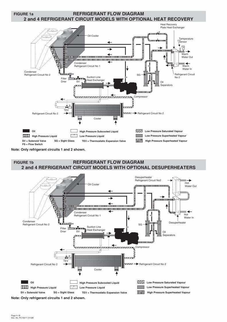
Cooling (Figure 1)Low pressure liquid refrigerant from the expansion valve (TEV) enters the counter-flow cooler tubes and is evaporated by the heatenergy absorbed from the chilled water passing through the shell. The refrigerant leaves the cooler in a saturated vapour state.
High pressure liquid refrigerant, from the condenser, enters the suction line heat exchanger shell and superheats the refrigerantvapour entering the tubes from the cooler. The low temperature liquid refrigerant, leaving the exchanger to the cooler, has beensub-cooled by the refrigerant vapour in the exchanger tubes.
Low-pressure superheated vapour enters the compressor where pressure and superheat are increased. High pressure vapour ispassed through the oil separator where compressor oil is removed and recirculated to the compressor via the oil cooler. The highpressure oil-free vapour is fed to the air cooled condenser coil and fans where the heat is removed. The high pressure liquidrefrigerant returns to the expansion valve via the suction line heat exchanger.
Optional Heat Recovery (Figure 1a)If the warm water flow switch detects water flow the heat recovery pressure regulating valves are energised. The valves allowhigh-pressure superheated refrigerant, from the oil separators, to enter the twin circuit heat recovery plate heat exchanger. Therefrigerant is partially condensed as the warm water absorbs heat energy.
The valves are de-energised when the leaving warm water temperature sensor registers the high point of the set point dead band. Ifwater flow is maintained the valves are re-energised if the temperature sensor registers the low point of the set point dead band.
Page H.17Doc. No. PC102/11.01/GB
OilSeparators
Oil Cooler
Condenser
High Pressure Superheated Vapour
Low Pressure Saturated VapourHigh Pressure Subcooled Liquid
Low Pressure Liquid
Oil
High Pressure Liquid
Low Pressure Superheated Vapour
SV = Solenoid Valve SG = Sight Glass TEV = Thermostatic Expansion Valve
Suction LineHeat Exchanger
Cooler
Compressor
FilterDrier
SG
TEV
SV
REFRIGERANT FLOW DIAGRAM FIGURE 1
Note: Only one refrigerant circuit shown.
0
5
25
75
95
100
0
5
25
75
95
100
0
5
25
75
95
100
0
5
25
75
95
100
Page H.18Doc. No. PC102/11.01/GB
High Pressure Superheated Vapour
Low Pressure Saturated VapourHigh Pressure Subcooled Liquid
Low Pressure Liquid
Oil
High Pressure Liquid Low Pressure Superheated Vapour
SV = Solenoid Valve SG = Sight Glass TEV = Thermostatic Expansion Valve
OilSeparators
Oil Cooler
CondenserRefrigerant Circuit No 2
CondenserRefrigerant Circuit No 1
Suction LineHeat Exchanger
Refrigerant Circuit No 2Refrigerant Circuit No 2
Cooler
Compressor
FilterDrier
SG
TEV
SV
FS
TemperatureSensor
WarmWater Out
WarmWater In
Refrigerant CircuitNo 2
Heat RecoveryPlate Heat Exchanger
FS = Flow Switch
FIGURE 1a REFRIGERANT FLOW DIAGRAM2 and 4 REFRIGERANT CIRCUIT MODELS WITH OPTIONAL HEAT RECOVERY
Note: Only refrigerant circuits 1 and 2 shown.
High Pressure Superheated Vapour
Low Pressure Saturated VapourHigh Pressure Subcooled Liquid
Low Pressure Liquid
Oil
High Pressure Liquid Low Pressure Superheated Vapour
SV = Solenoid Valve SG = Sight Glass TEV = Thermostatic Expansion Valve
OilSeparators
Oil Cooler
CondenserRefrigerant Circuit No 2
CondenserRefrigerant Circuit No 1
Suction LineHeat Exchanger
Refrigerant Circuit No 2Refrigerant Circuit No 2
Cooler
Compressor
FilterDrier
SG
TEV
SV
HotWater In
Desuperheater
DesuperheaterRefrigerant Circuit No2
HotWater Out
FIGURE 1b REFRIGERANT FLOW DIAGRAM2 and 4 REFRIGERANT CIRCUIT MODELS WITH OPTIONAL DESUPERHEATERS
Note: Only refrigerant circuits 1 and 2 shown.
0
5
25
75
95
100
0
5
25
75
95
100
0
5
25
75
95
100
0
5
25
75
95
100

Page H.19Doc. No. PC102/11.01/GB
OPERATING LIMITATIONS TABLE 2
Min. Max. Min. Max. Min. Max. Min. Max. Min. Max.Chilled Liquid outlet Water outlet °C
Liquid temperature Glycol outlet °CTemp. spread °C
Flow rate l/s 18.5 67.6 21.0 75.7 21.0 75.7 21.0 75.7 21.0 75.7Pressure drop kPa 8.8 97.2 9.3 92.4 9.3 92.4 9.3 92.4 9.3 92.4Maximum working pressure bar
Ambient Air Entering Standard units °CAir temperature Low sound fans °C
High pressure fans °CFan Standard units PaAvailable Static Low sound fans PaPressure High pressure fans Pa
Power supply voltage 400 V, 3 Ø, 50 Hz (nominal) VRecommended system water volume (2) l 2215 2500 2650 2875 2950
0905
10 (21.0 Optional)
0965
5 to 13
-2 to 13 (1)
0685 0775 0835
-18 to 46-18 to 50
20
3 to 10
-18 to 50
10150
342 to 440
Model YCAS-EB
3 Refrigerant Circuit Models
Notes: (1) -2°C is the minimum leaving chilled liquid temp. (LCLT) for standard coded vessels. ASME coded vesselsand other codes with special materials have a minimum LCLT of -9.7°C.
(2) Tables show minimum water / glycol volume of system.
Min. Max. Min. Max. Min. Max. Min. Max. Min. Max.Chilled Liquid outlet Water outlet °C
Liquid temperature Glycol outlet °CTemp. spread °C
Flow rate l/s 6.94 25.42 7.70 25.42 8.58 25.42 9.53 37.85 10.60 42.27Pressure drop kPa 6.2 72.9 7.5 72.9 9.3 72.9 6.0 61.3 7.1 73.9Maximum working pressure bar
Ambient Air Entering Standard units °CAir temperature Low sound fans °C
High pressure fans °CFan Standard units PaAvailable Static Low sound fans PaPressure High pressure fans Pa
Power supply voltage 400 V, 3 Ø, 50 Hz (nominal) VRecommended system water volum (2) l 835 985 1165 1275 1430
-18 to 46-18 to 50
10.3 (21.0 Optional)
3 to 10
0475
5 to 13
-2 to 13 (1)
0295 0335 0375 0425
-18 to 502010
150342 to 440
Model YCAS-EB
2 Refrigerant Circuit Models
Min. Max. Min. Max. Min. Max. Min. Max.Chilled Liquid outlet Water outlet °C
Liquid temperature Glycol outlet °CTemp. spread °C
Flow rate l/s 11.67 46.87 12.37 48.45 13.06 48.45 13.63 48.45Pressure drop kPa 8.4 88.0 9.3 93.1 10.2 93.1 10.9 93.1Maximum working pressure bar
Ambient Air Entering Standard units °CAir temperature Low sound fans °C
High pressure fans °CFan Standard units PaAvailable Static Low sound fans PaPressure High pressure fans Pa
Power supply voltage 400 V, 3 Ø, 50 Hz (nominal) VRecommended system water volume (2) l
0515 0555 0575 0605
5 to 13
-2 to 13 (1)
3 to 10
10.3 (21.0 Optional)-18 to 50-18 to 46-18 to 50
2010
150342 to 440
1585 1685 1785 1865
Model YCAS-EB
2 Refrigerant Circuit Models
0
5
25
75
95
100
0
5
25
75
95
100
0
5
25
75
95
100
0
5
25
75
95
100

SELECTION GUIDEDATA REQUIREDTo select a YORK YCAS chiller the following information isrequired:
1. Required cooling capacity.
2. Design chilled water entering and leaving temperatures.
3. Design water flow rate if one of the temperatures in item 3are unknown.
4. Design condenser entering air temperature. This willnormally be the design summer ambient air temperatureunless location or other factors have an influence.
5. Altitude above sea level.
6. Design cooler fouling factor.
7. Static pressure resistance against condenser entering andleaving air flow (where ducts, louvres, attenuators, etc., areused) at full unit air volume.
Note: Items 1, 2 and 3 must be linked by the following formulae:
Cooling Capacity (kW) = Range (°C) x Flow (litres/sec) x 4.18
Where:Range = Entering liquid temperature - Leaving liquidtemperature.
CHILLER SELECTION METHOD1. Determine the correct size of chiller by selecting the model
which most closely matches the required capacity at thedesign conditions of leaving water temperature andentering air temperature (Table 7).
2. Apply correction factors for fouling factor (Table 3) andaltitude & fan application (Tables 4 & 5) to the capacity andpower values from the capacity tables (Table 7). Ensure thecorrected capacity is still sufficient for requirements.
3. Using the corrected capacity of the selected chiller adjustthe design temperature range, or flow rate, to balance theformulae shown in “Data Required”.
4. Physical and electrical data can now be determined fromTables 9 and 10.
5. Always re-check that selections fall within the designlimitations specified in Table 2.
TABLE 3 FOULING FACTORS
TABLE 4 ALTITUDE FACTORS
TABLE 5 FAN APPLICATION FACTORS
Page H.20Doc. No. PC102/11.01/GB
TABLE 2 OPERATING LIMITATIONS
Min. Max. Min. Max. Min. Max.Chilled Liquid outlet Water outlet °C
Liquid temperature Glycol outlet °CTemp. spread °C
Flow rate l/s 27.2 100.9 27.2 100.9 27.2 100.9Pressure drop kPa 10.3 93.7 10.3 93.7 10.3 93.7Maximum working pressure bar
Ambient Air Entering Standard units °CAir temperature Low sound fans °C
High pressure fans °CFan Standard units PaAvailable Static Low sound fans PaPressure High pressure fans Pa
Power supply voltage 400 V, 3 Ø, 50 Hz (nominal) VRecommended system water volume (2) l 3375 3600 3825
5 to 13
-2 to 13 (1)
1065 1135 1215
3 to 10
10 (21.0 Optional)-18 to 50-18 to 46
342 to 440
-18 to 502010
150
Model YCAS-EB
Notes: (1) -2°C is the minimum leaving chilled liquid temp. (LCLT) for standard coded vessels. ASME coded vesselsand other codes with special materials have a minimum LCLT of -9.7°C.
(2) Table shows minimum water / glycol volume of system.
4 Refrigerant Circuit Models
COOLERFouling Factor m² °C/kW Capacity Factor Comp. Input Factor
0.044 1.000 1.0000.088 0.987 0.9950.176 0.964 0.9850.352 0.915 0.962
Altitude (m) Capacity Factor Comp. Input Factor0 1.000 1.000
600 0.987 1.0101200 0.973 1.0201800 0.958 1.0292400 0.943 1.038
Fan Type External Static (Pa) Capacity Factor Comp. Input FactorLow Sound Fans 0 1.00 1.00
10 0.99 1.01Standard Fans 0 1.00 1.00
20 0.99 1.01High Pressure
Fans150 1.00 1.00
0
5
25
75
95
100
0
5
25
75
95
100
0
5
25
75
95
100
0
5
25
75
95
100

COOLING ONLY CHILLER SAMPLE SELECTIONA chiller is required to cool water from 12°C to 7°C having acooling capacity of 575 kW at a design flow rate of 28 l/s. Otherdesign conditions applying are:
Ambient air entering condenser: 35°CFouling factor: 0.044 m² °C./kWAltitude: Sea levelCondenser air restriction: None
From a cursory examination of Capacity Table 7, a model0605EB gives approximately the required capacity:
Capacity = 584 kWCompressor power = 179.7 kW
No correction factors apply therefore, after calculating the flowrate, the conditions will be as follows:
Cooling capacity: 584 kWWater temperature: 12°C to 7°C (Range = 5°C)Water flow rate: 27.95 I/sCompressor power: 179.7 kW
All values are within the operating limits in Table 2. FromPressure Drop Graph (Figure 2), YCAS0605EB cooler waterpressure drop = 36.7 kPa at the calculated flow of 27.95 l/s.
COOLER WATER PRESSURE DROPS FIGURE 2
OPTIONAL HEAT RECOVERY SAMPLE SELECTIONA chiller is required to cool water from 12°C to 7°C having acooling capacity of approximately 575 kW at a design flow rateof 28 l/s. Other design conditions applying are:
Ambient air entering condenser: 35°CFouling factor: 0.044 m² °C./kWAltitude: Sea levelCondenser air restriction: NoneRequired leaving Temperature 50°CHot water temperature range 12°C
A model 0605EB meets the cooling requirements, see sampleselection opposite.
From Table 8 a model 0605EB gives the following data whenproviding hot water at 50°C.
LWT Cool (kW) Power (kW) Heat (kW)
7°C 510 226 393
The heating capacity should be corrected for the hot watertemperature range Table 6: 393 kW x 1.02 = 400.8
Heat recovery water flow: 400.8 = 7.99 l/s12°C x 4.18
Heat recovery pressure drop from graph (Figure 3) is 46 kPa atthe calculated flow of 7.99 l/s.
TEMPERATURE RANGE FACTORS TABLE 6
FIGURE 3 HEAT RECOVERY PRESSURE DROP
FIGURE 4 DESUPERHEATERS PRESSURE DROP
Page H.21Doc. No. PC102/11.01/GB
Model Line Pressure Drop Calculation
0295, 0335, 1 Pressure Drop [kPa] = 0.1556 x (Flow Rate [l/s]1.9004)
0375
0425, 0475, 2 Pressure Drop [kPa] = 0.1320 x (Flow Rate [l/s]1.6901)
0515, 0555,0575, 0605
0685 3 Pressure Drop [kPa] = 0.0396 x (Flow Rate [l/s]1.8523)
0775, 0835, 4 Pressure Drop [kPa] = 0.0394 x (Flow Rate [l/s]1.7935)
0905, 0965
1065, 1135, 5 Pressure Drop [kPa] = 0.0396 x (Flow Rate [l/s]1.6837)
1215
10 15 20 25 30 35 40 4550 60 10055
10
15
20
25
30
35404550
60
708090
100
Flow Rate (l/s)
Pre
ssur
eD
rop
(kP
a)
31
4
2
5
80
Temperature Capacity Temperature CapacityRange Factor Range Factor
8 0.98 11 1.019 0.99 12 1.02
13 1.0314 1.04
10 1.00
Flow Rate (l/s)
Pre
ssur
eD
rop
(kP
a)
0
40
60
120
140
160
100
80
5 10 15 20
Flow Rate (l/s)
Pre
ssur
eD
rop
(kP
a)
0101520
30354045
25
0.5 1.5 2.51 2 3
The water pressure drop values shown in figures 3 and 4 are fortwo refrigerant circuit models with flow rates based on 10°C hotwater temperature range.
On four refrigerant circuit models two heat recovery condensersor two pairs of desuperheaters are fitted. Both options are tohave their heat exchanger water circuits connected in parallel.
When connected in this configuration the water flow will beequally divided through the heat exchangers, therefore the totalflow should be divided by 2 when calculating the pressure drop.
0
5
25
75
95
100
0
5
25
75
95
100
0
5
25
75
95
100
0
5
25
75
95
100

Page H.22Doc. No. PC102/11.01/GB
LeavingModel Water 25 30 35 40 45
Temp. Cool Power Cool Power Cool Power Cool Power Cool Power Cool Power°C kW kW kW kW kW kW kW kW kW kW kW kW5.0 274 60.4 260 67.8 244 76.6 229 86.4 214 97.4 200 109.46.0 283 60.1 269 67.6 252 76.2 236 86.0 221 96.9 208 108.77.0 292 59.9 277 67.3 260 75.9 244 85.7 229 96.4 215 108.1
YCAS 8.0 301 59.7 285 67.1 269 75.7 252 85.3 236 96.0 222 107.60295EB 9.0 310 59.5 293 66.9 277 75.5 260 85.1 244 95.7 230 107.2
10.0 319 59.2 301 66.7 285 75.3 268 84.9 252 95.4 237 106.811.0 328 59.1 309 66.6 294 75.2 276 84.8 260 95.3 243 105.812.0 337 58.9 317 66.5 302 75.1 285 84.7 268 95.2 245 103.713.0 346 58.7 326 66.4 311 75.1 293 84.7 276 95.2 249 102.25.0 327 77.6 309 87.4 289 98.7 271 111.4 253 125.4 212 125.96.0 338 77.7 318 87.5 299 98.8 282 111.5 262 125.4 217 124.47.0 348 77.8 328 87.6 308 98.8 289 111.3 271 125.2 222 123.1
YCAS 8.0 358 77.9 338 87.7 318 98.9 298 111.4 280 125.1 227 121.70335EB 9.0 368 78.0 348 87.8 327 99.0 308 111.4 289 125.1 233 120.1
10.0 379 78.0 357 87.9 337 99.1 317 111.5 298 125.1 237 119.511.0 389 78.1 367 88.0 347 99.2 327 111.7 307 125.2 241 118.012.0 399 78.2 377 88.2 357 99.4 336 111.8 317 125.4 244 116.113.0 410 78.2 388 88.3 367 99.5 346 112.0 326 125.6 247 114.55.0 389 94.9 365 107.1 342 121.0 320 136.4 299 153.6 227 142.36.0 400 95.4 376 107.6 353 121.4 330 136.7 309 153.9 230 140.07.0 412 95.8 387 108.1 364 121.8 341 137.1 320 154.1 234 138.1
YCAS 8.0 424 96.2 399 108.5 375 122.2 352 137.5 330 154.3 236 135.70375EB 9.0 435 96.6 411 108.8 386 122.6 363 137.9 341 154.6 240 134.0
10.0 447 96.9 422 109.2 398 122.9 374 138.3 352 154.9 242 132.111.0 459 97.2 434 109.6 409 123.3 385 138.7 363 155.3 245 130.212.0 471 97.5 446 109.9 421 123.7 396 139.0 373 155.6 248 128.513.0 483 97.8 459 110.3 432 124.1 408 139.3 385 156.0 250 126.85.0 425 87.2 399 98.4 373 111.2 349 125.5 326 141.4 305 158.86.0 437 87.4 412 98.6 385 111.3 360 125.5 337 141.4 316 158.77.0 450 87.5 424 98.7 397 111.5 372 125.7 348 141.4 327 158.6
YCAS 8.0 463 87.7 437 98.9 410 111.6 384 125.7 359 141.4 338 158.50425EB 9.0 477 87.8 450 99.0 422 111.6 396 125.8 371 141.4 346 157.5
10.0 490 87.9 463 99.1 435 111.7 408 125.9 383 141.4 349 154.311.0 505 87.8 476 99.1 448 111.8 420 125.9 395 141.4 355 152.212.0 518 87.8 489 99.2 461 111.9 433 126.0 407 141.5 361 150.013.0 533 87.8 502 99.2 474 112.0 445 126.1 419 141.6 365 147.65.0 478 103.6 449 116.9 420 131.8 392 148.6 367 167.3 318 174.16.0 492 104.0 462 117.2 433 132.2 405 148.9 379 167.5 326 172.57.0 507 104.3 476 117.6 446 132.5 418 149.2 391 167.6 333 170.9
YCAS 8.0 521 104.6 491 117.9 460 132.8 431 149.4 404 167.8 341 169.40475EB 9.0 536 104.9 505 118.1 474 133.1 444 149.7 417 168.0 347 167.5
10.0 551 105.1 542 118.5 488 133.3 458 150.0 430 168.2 351 164.611.0 598 105.4 534 118.7 502 133.6 471 150.3 443 168.4 356 162.212.0 581 105.6 577 118.9 516 133.9 485 150.5 456 168.7 361 159.913.0 596 105.8 563 119.1 530 134.2 499 150.8 470 169.0 364 157.55.0 532 120.1 498 135.3 466 152.5 436 171.8 408 193.2 331 189.36.0 547 120.6 513 135.9 481 153.1 450 172.2 421 193.6 336 186.27.0 563 121.1 529 136.4 495 153.6 464 172.7 435 193.9 340 183.3
YCAS 8.0 579 121.6 544 136.9 510 154.0 478 173.2 449 194.2 344 180.40515EB 9.0 596 122.0 560 137.4 526 154.5 493 173.7 463 194.6 349 177.6
10.0 612 122.5 576 137.8 541 155.0 507 174.2 477 195.0 353 174.911.0 628 123.0 592 138.3 556 155.5 522 174.6 491 195.5 356 172.312.0 644 123.4 608 138.7 572 156.0 538 175.0 506 195.9 360 169.813.0 660 123.8 624 139.1 587 156.5 553 175.5 521 196.4 364 167.45.0 566 136.1 530 153.4 496 172.8 463 194.5 418 209.6 326 199.46.0 582 136.8 546 154.1 511 173.5 478 195.2 432 209.8 331 196.37.0 599 137.6 562 154.9 527 174.2 493 195.8 445 209.9 335 193.4
YCAS 8.0 616 138.3 578 155.5 542 174.9 508 196.5 459 210.1 339 190.50555EB 9.0 633 138.9 595 156.1 558 175.5 524 197.1 472 210.3 343 187.8
10.0 650 139.5 611 156.8 574 176.2 539 197.8 486 210.5 347 185.111.0 667 140.2 628 157.5 591 176.9 555 198.5 500 210.7 350 182.512.0 684 140.8 645 158.2 607 177.6 571 199.1 514 211.0 354 180.113.0 701 141.3 662 158.8 623 178.3 587 199.8 528 211.1 357 177.75.0 599 152.1 561 171.4 525 193.0 491 217.3 429 226.0 322 209.56.0 617 153.1 578 172.3 541 193.9 507 218.2 442 226.0 326 206.47.0 634 154.1 595 173.4 558 194.8 523 219.0 455 226.0 330 203.5
YCAS 8.0 652 155.0 613 174.0 574 195.7 539 219.8 468 226.0 334 200.70575EB 9.0 670 155.8 630 174.9 591 196.6 555 220.6 482 226.0 338 197.9
10.0 688 156.6 647 175.7 608 197.4 571 221.5 495 226.0 341 195.311.0 706 157.5 664 176.9 625 198.3 588 222.3 509 226.0 345 192.712.0 724 158.2 682 177.7 642 199.2 604 223.2 523 226.0 348 190.313.0 743 158.9 700 178.6 660 200.1 621 224.1 536 225.7 351 187.95.0 625 140.8 586 158.5 549 178.6 513 201.2 479 226.0 398 226.06.0 643 141.5 604 159.3 566 179.1 530 201.7 495 226.0 411 226.07.0 662 142.0 622 159.8 584 179.7 546 202.2 510 226.0 425 226.0
YCAS 8.0 681 142.6 640 160.4 606 180.5 563 202.7 525 226.0 438 226.00605EB 9.0 700 143.1 658 160.9 618 180.9 581 203.0 541 226.0 450 225.0
10.0 719 143.5 677 161.4 636 181.5 598 203.6 556 226.0 456 221.511.0 738 143.9 696 161.9 654 182.0 615 204.3 572 226.0 461 217.912.0 757 144.3 715 162.4 673 182.5 633 204.8 588 226.0 466 214.413.0 776 144.7 734 162.8 691 183.0 651 205.4 603 226.0 471 211.1
50Condenser Entering Air Temperature °C
TABLE 7 2 REFRIGERANT CIRCUIT MODELSCOOLING CAPACITIES
0
5
25
75
95
100
0
5
25
75
95
100
0
5
25
75
95
100
0
5
25
75
95
100

Page H.23Doc. No. PC102/11.01/GB
Leaving Condenser Entering Air Temperature °CModel Water 25 30 35 40 45 50
Temp. Cool Power Cool Power Cool Power Cool Power Cool Power Cool Power°C kW kW kW kW kW kW kW kW kW kW kW kW5.0 743 166.3 695 187.5 650 211.5 608 238.2 558 262.7 448 256.56.0 764 167.1 717 188.2 671 212.1 627 238.8 577 262.9 455 252.67.0 786 167.8 738 188.9 692 212.8 647 239.4 595 263.1 461 248.7
YCAS 8.0 809 168.4 760 189.5 713 213.4 667 239.9 614 263.3 467 245.00685EB 9.0 831 168.9 782 190.0 734 213.9 688 240.5 633 263.4 473 241.4
10.0 853 169.4 804 190.7 755 214.5 709 241.0 652 263.7 479 237.911.0 876 169.8 827 191.3 777 215.1 730 241.6 671 263.9 484 234.512.0 900 170.3 849 191.8 799 215.7 751 242.2 691 264.1 489 231.313.0 938 170.8 872 192.4 821 216.3 772 242.8 710 264.3 495 228.25.0 839 175.2 786 197.5 735 222.7 687 251.0 643 282.3 567 299.06.0 864 175.8 810 198.1 759 223.3 709 251.4 664 282.6 576 294.07.0 889 176.3 835 198.7 782 223.8 732 251.9 686 282.9 584 289.1
YCAS 8.0 915 176.8 860 199.2 806 224.3 755 252.3 708 283.3 592 284.40775EB 9.0 940 177.3 885 199.7 830 224.8 778 252.8 730 283.6 600 279.8
10.0 965 177.7 910 200.1 855 225.3 802 253.2 753 284.0 607 275.311.0 990 178.4 936 200.6 879 225.7 826 253.7 776 284.4 614 271.012.0 1015 178.7 961 201.0 904 226.2 850 254.2 799 284.8 621 266.913.0 1042 179.0 987 201.4 929 226.7 874 254.7 823 285.3 628 262.85.0 891 190.8 834 214.9 780 242.2 728 272.7 671 301.3 568 307.26.0 917 191.6 859 215.7 804 242.9 752 273.4 693 301.5 576 302.37.0 943 192.3 885 216.4 829 243.6 775 274.0 715 301.7 584 297.4
YCAS 8.0 970 193.0 911 217.0 854 244.3 800 274.7 737 301.9 591 292.70835EB 9.0 997 193.6 937 217.7 879 244.9 824 275.2 760 302.2 599 288.2
10.0 1023 194.3 964 218.4 905 245.6 849 275.8 782 302.5 606 283.811.0 1050 194.8 990 219.1 930 246.2 874 276.5 805 302.7 613 279.512.0 1078 195.3 1017 219.7 956 246.9 899 277.1 829 303.0 619 275.413.0 1106 195.8 1044 220.3 983 247.6 924 277.9 852 303.3 625 271.55.0 966 221.3 904 249.1 845 280.6 790 315.8 708 339.0 562 327.86.0 993 222.7 932 250.2 872 281.7 815 316.9 730 339.0 569 322.77.0 1022 223.7 959 251.3 898 282.7 841 318.0 752 339.0 576 317.9
YCAS 8.0 1051 224.7 987 252.3 925 283.7 866 318.9 775 339.0 584 313.20905EB 9.0 1080 225.6 1015 253.5 952 284.7 893 319.7 797 339.0 590 308.6
10.0 1109 226.5 1042 254.7 980 285.7 919 320.6 820 339.0 597 304.211.0 1139 227.4 1071 255.6 1007 286.7 946 321.6 843 339.0 603 300.012.0 1169 228.2 1100 256.6 1035 287.8 973 322.6 866 339.0 609 295.913.0 1198 229.0 1129 257.5 1063 288.9 1000 323.7 889 339.0 615 291.95.0 990 211.4 928 237.9 869 267.7 812 301.4 751 334.8 630 339.06.0 1020 212.3 956 238.8 896 268.5 838 302.2 775 334.8 652 339.07.0 1049 213.1 985 239.7 923 269.3 864 302.9 799 334.8 668 336.3
YCAS 8.0 1090 214.1 1014 240.4 950 270.4 891 303.6 823 334.9 681 332.60965EB 9.0 1108 214.5 1043 241.2 978 271.1 918 304.3 848 335.0 694 329.1
10.0 1173 216.1 1072 241.9 1007 271.9 945 305.2 873 335.0 707 325.711.0 1169 215.8 1101 242.6 1035 272.7 972 306.1 897 335.3 720 322.412.0 1199 216.4 1131 243.3 1064 273.5 1000 306.9 922 335.4 732 319.213.0 1230 216.9 1161 244.0 1093 274.2 1028 307.7 947 335.6 744 316.2
3 REFRIGERANT CIRCUIT MODELS TABLE 7COOLING CAPACITIES
Leaving Condenser Entering Air Temperature °CModel Water 25 30 35 40 45 50
Temp. Cool Power Cool Power Cool Power Cool Power Cool Power Cool Power°C kW kW kW kW kW kW kW kW kW kW kW kW5.0 1134 234.0 1062 263.7 993 297.3 927 334.9 867 376.6 760 396.56.0 1168 234.8 1094 264.5 1024 298.0 957 335.5 896 377.0 771 389.97.0 1202 235.4 1127 265.2 1056 299.1 988 336.1 925 377.4 782 383.4
YCAS 8.0 1236 236.1 1161 265.8 1088 299.3 1019 336.6 955 377.9 793 377.21065EB 9.0 1270 236.6 1194 266.5 1120 300.0 1050 337.2 985 378.3 803 371.1
10.0 1303 237.4 1229 267.1 1153 300.6 1082 337.9 1015 378.8 813 365.211.0 1337 238.0 1249 267.3 1186 301.3 1114 338.5 1046 379.4 822 359.612.0 1372 238.5 1298 268.2 1219 301.9 1146 339.2 1077 380.0 831 354.113.0 1409 238.9 1332 268.9 1253 302.6 1178 339.9 1109 380.6 840 348.85.0 1208 264.4 1132 297.8 1058 335.6 989 377.9 904 414.3 754 417.06.0 1244 265.8 1166 298.9 1091 336.7 1020 378.9 933 414.5 765 410.47.0 1280 266.8 1201 300.0 1125 337.7 1052 379.9 963 414.7 775 403.9
YCAS 8.0 1316 267.7 1236 301.0 1159 338.8 1085 380.9 992 414.9 785 397.61135EB 9.0 1352 268.6 1272 302.0 1193 339.7 1118 381.7 1022 415.2 795 391.5
10.0 1389 269.7 1307 303.2 1227 340.7 1152 382.6 1053 415.4 804 385.611.0 1425 270.5 1343 304.1 1262 341.7 1185 383.6 1083 415.7 813 380.012.0 1463 271.3 1380 305.1 1297 342.7 1220 384.6 1114 416.0 821 374.513.0 1501 272.1 1416 306.0 1333 343.8 1254 385.6 1145 416.3 830 369.25.0 1283 294.9 1202 332.0 1124 374.0 1050 421.0 941 452.0 748 437.66.0 1320 296.8 1238 333.5 1159 375.5 1084 422.3 971 452.0 758 430.87.0 1358 298.2 1275 334.9 1194 376.8 1117 423.8 1000 452.0 768 424.3
YCAS 8.0 1396 299.5 1312 336.2 1230 378.2 1152 425.1 1030 452.0 777 418.01215EB 9.0 1435 300.7 1349 337.6 1266 379.5 1187 426.2 1060 452.0 786 411.9
10.0 1474 301.9 1386 339.4 1302 380.8 1222 427.4 1090 452.0 795 406.111.0 1514 303.1 1424 340.7 1339 382.2 1257 428.7 1121 452.0 804 400.412.0 1553 304.2 1462 341.9 1376 383.6 1293 430.0 1151 452.0 812 394.913.0 1593 305.3 1501 343.2 1413 385.0 1329 431.5 1182 452.0 820 389.6
4 REFRIGERANT CIRCUIT MODELS TABLE 7COOLING CAPACITIES
0
5
25
75
95
100
0
5
25
75
95
100
0
5
25
75
95
100
0
5
25
75
95
100

Page H.24Doc. No. PC102/11.01/GB
LeavingModel Chilled 30 35 40 45 50
Water Cool Power Heat Cool Power Heat Cool Power Heat Cool Power Heat Cool Power HeatTemp. °C kW kW kW kW kW kW kW kW kW kW kW kW kW kW kW
5.0 274 60.4 275 260 67.8 260 244 76.6 241 229 86.4 216 214 97.4 1666.0 283 60.1 282 269 67.6 266 252 76.2 247 236 86.0 221 221 96.9 1707.0 292 59.9 289 277 67.3 272 260 75.9 253 244 85.7 227 229 96.4 174
YCAS 8.0 301 59.7 296 285 67.1 279 269 75.7 259 252 85.3 232 236 96.0 1780295EB 9.0 310 59.5 304 293 66.9 285 277 75.5 265 260 85.1 237 244 95.7 182
10.0 319 59.2 311 301 66.7 291 285 75.3 271 268 84.9 242 252 95.4 18611.0 328 59.1 318 309 66.6 297 294 75.2 277 276 84.8 248 260 95.3 19012.0 337 58.9 325 317 66.5 304 302 75.1 284 285 84.7 254 268 95.2 19413.0 346 58.7 332 326 66.4 311 311 75.1 290 293 84.7 259 276 95.2 1985.0 327 77.6 333 309 87.4 314 289 98.7 292 271 111.4 262 253 125.4 2036.0 338 77.7 341 318 87.5 321 299 98.8 299 282 111.5 270 262 125.4 2077.0 348 77.8 350 328 87.6 329 308 98.8 306 289 111.3 275 271 125.2 212
YCAS 8.0 358 77.9 358 338 87.7 337 318 98.9 313 298 111.4 281 280 125.1 2170335EB 9.0 368 78.0 367 348 87.8 345 327 99.0 321 308 111.4 288 289 125.1 221
10.0 379 78.0 375 357 87.9 352 337 99.1 328 317 111.5 294 298 125.1 22611.0 389 78.1 384 367 88.0 360 347 99.2 336 327 111.7 301 307 125.2 23112.0 399 78.2 392 377 88.2 368 357 99.4 343 336 111.8 308 317 125.4 23613.0 410 78.2 401 388 88.3 377 367 99.5 351 346 112.0 315 326 125.6 2415.0 389 94.9 397 365 107.1 373 342 121.0 348 320 136.4 313 299 153.6 2426.0 400 95.4 407 376 107.6 383 353 121.4 357 330 136.7 321 309 153.9 2487.0 412 95.8 417 387 108.1 392 364 121.8 365 341 137.1 328 320 154.1 253
YCAS 8.0 424 96.2 427 399 108.5 402 375 122.2 374 352 137.5 336 330 154.3 2590375EB 9.0 435 96.6 437 411 108.8 411 386 122.6 383 363 137.9 344 341 154.6 265
10.0 447 96.9 447 422 109.2 421 398 122.9 392 374 138.3 352 352 154.9 27111.0 459 97.2 457 434 109.6 431 409 123.3 401 385 138.7 359 363 155.3 27712.0 471 97.5 467 446 109.9 440 421 123.7 410 396 139.0 368 373 155.6 28313.0 483 97.8 478 459 110.3 450 432 124.1 419 408 139.3 376 385 156.0 2895.0 425 87.2 421 399 98.4 394 373 111.2 364 349 125.5 326 326 141.4 2506.0 437 87.4 431 412 98.6 404 385 111.3 374 360 125.5 334 337 141.4 2567.0 450 87.5 442 424 98.7 414 397 111.5 383 372 125.7 342 348 141.4 262
YCAS 8.0 463 87.7 453 437 98.9 424 410 111.6 392 384 125.7 350 359 141.4 2680425EB 9.0 477 87.8 464 450 99.0 435 422 111.6 402 396 125.8 358 371 141.4 274
10.0 490 87.9 475 463 99.1 445 435 111.7 411 408 125.9 367 383 141.4 28011.0 505 87.8 487 476 99.1 455 448 111.8 421 420 125.9 375 395 141.4 28712.0 518 87.8 498 489 99.2 465 461 111.9 431 433 126.0 384 407 141.5 29313.0 533 87.8 510 502 99.2 476 474 112.0 441 445 126.1 392 419 141.6 3005.0 478 103.6 478 449 116.9 448 420 131.8 415 392 148.6 371 367 167.3 2856.0 492 104.0 490 462 117.2 459 433 132.2 425 405 148.9 380 379 167.5 2927.0 507 104.3 502 476 117.6 470 446 132.5 435 418 149.2 389 391 167.6 299
YCAS 8.0 521 104.6 514 491 117.9 482 460 132.8 446 431 149.4 399 404 167.8 3060475EB 9.0 536 104.9 527 505 118.1 493 474 133.1 457 444 149.7 408 417 168.0 313
10.0 551 105.1 539 542 118.5 523 488 133.3 467 458 150.0 417 430 168.2 32011.0 598 105.4 578 534 118.7 516 502 133.6 478 471 150.3 427 443 168.4 32712.0 581 105.6 564 577 118.9 551 516 133.9 489 485 150.5 436 456 168.7 33413.0 596 105.8 577 563 119.1 540 530 134.2 500 499 150.8 446 470 169.0 3415.0 532 120.1 536 498 135.3 501 466 152.5 465 436 171.8 417 408 193.2 3216.0 547 120.6 549 513 135.9 514 481 153.1 477 450 172.2 427 421 193.6 3297.0 563 121.1 562 529 136.4 526 495 153.6 488 464 172.7 437 435 193.9 336
YCAS 8.0 579 121.6 576 544 136.9 539 510 154.0 500 478 173.2 447 449 194.2 3440515EB 9.0 596 122.0 590 560 137.4 552 526 154.5 512 493 173.7 458 463 194.6 351
10.0 612 122.5 603 576 137.8 565 541 155.0 524 507 174.2 468 477 195.0 35911.0 628 123.0 617 592 138.3 578 556 155.5 535 522 174.6 479 491 195.5 36712.0 644 123.4 630 608 138.7 591 572 156.0 547 538 175.0 489 506 195.9 37513.0 660 123.8 644 624 139.1 604 587 156.5 560 553 175.5 500 521 196.4 3835.0 566 136.1 577 530 153.4 541 496 172.8 503 463 194.5 452 418 209.6 3366.0 582 136.8 591 546 154.1 554 511 173.5 515 478 195.2 462 432 209.8 3437.0 599 137.6 605 562 154.9 567 527 174.2 527 493 195.8 473 445 209.9 350
YCAS 8.0 616 138.3 619 578 155.5 581 542 174.9 540 508 196.5 484 459 210.1 3570555EB 9.0 633 138.9 634 595 156.1 594 558 175.5 552 524 197.1 495 472 210.3 365
10.0 650 139.5 648 611 156.8 608 574 176.2 565 539 197.8 506 486 210.5 37211.0 667 140.2 663 628 157.5 622 591 176.9 577 555 198.5 517 500 210.7 38012.0 684 140.8 678 645 158.2 636 607 177.6 590 571 199.1 529 514 211.0 38813.0 701 141.3 692 662 158.8 650 623 178.3 603 587 199.8 540 528 211.1 3955.0 599 152.1 618 561 171.4 580 525 193.0 540 491 217.3 487 429 226.0 3506.0 617 153.1 632 578 172.3 594 541 193.9 553 507 218.2 498 442 226.0 3577.0 634 154.1 648 595 173.4 608 558 194.8 566 523 219.0 509 455 226.0 364
YCAS 8.0 652 155.0 663 613 174.0 623 574 195.7 579 539 219.8 521 468 226.0 3710575EB 9.0 670 155.8 678 630 174.9 637 591 196.6 593 555 220.6 533 482 226.0 378
10.0 688 156.6 694 647 175.7 651 608 197.4 606 571 221.5 544 495 226.0 38611.0 706 157.5 709 664 176.9 666 625 198.3 620 588 222.3 556 509 226.0 39312.0 724 158.2 725 682 177.7 681 642 199.2 633 604 223.2 568 523 226.0 40013.0 743 158.9 741 700 178.6 695 660 200.1 647 621 224.1 580 536 225.7 4075.0 625 140.8 629 586 158.5 589 549 178.6 547 513 201.2 491 479 226.0 3776.0 643 141.5 645 604 159.3 604 566 179.1 561 530 201.7 502 495 226.0 3857.0 662 142.0 661 622 159.8 619 584 179.7 574 546 202.2 514 510 226.0 393
YCAS 8.0 681 142.6 677 640 160.4 634 606 180.5 592 563 202.7 526 525 226.0 4020605EB 9.0 700 143.1 693 658 160.9 648 618 180.9 601 581 203.0 538 541 226.0 410
10.0 719 143.5 709 677 161.4 664 636 181.5 615 598 203.6 551 556 226.0 41811.0 738 143.9 725 696 161.9 679 654 182.0 629 615 204.3 563 572 226.0 42712.0 757 144.3 741 715 162.4 694 673 182.5 643 633 204.8 575 588 226.0 43513.0 776 144.7 757 734 162.8 710 691 183.0 658 651 205.4 588 603 226.0 443
Heat recovery capacities (Heat) are for a leaving hot water temperature range of 10°C, where range = leaving liquid temperature - entering liquid temperature.
Leaving Hot Water Temperature °C
TABLE 8 2 REFRIGERANT CIRCUIT MODELSHEAT RECOVERY CAPACITIES
0
5
25
75
95
100
0
5
25
75
95
100
0
5
25
75
95
100
0
5
25
75
95
100

Page H.25Doc. No. PC102/11.01/GB
LeavingModel Chilled 30 35 40 45 50
Water Cool Power Heat Cool Power Heat Cool Power Heat Cool Power Heat Cool Power HeatTemp. °C kW kW kW kW kW kW kW kW kW kW kW kW kW kW kW
5.0 1134 234.0 1124 1062 263.7 1049 993 297.3 970 927 334.9 867 867 376.6 6656.0 1168 234.8 1152 1094 264.5 1075 1024 298.0 995 957 335.5 888 896 377.0 6807.0 1202 235.4 1181 1127 265.2 1102 1056 299.1 1020 988 336.1 909 925 377.4 696
YCAS 8.0 1236 236.1 1209 1161 265.8 1129 1088 299.3 1044 1019 336.6 931 955 377.9 7121065EB 9.0 1270 236.6 1238 1194 266.5 1156 1120 300.0 1068 1050 337.2 953 985 378.3 729
10.0 1303 237.4 1266 1229 267.1 1184 1153 300.6 1094 1082 337.9 975 1015 378.8 74511.0 1337 238.0 1294 1249 267.3 1200 1186 301.3 1119 1114 338.5 997 1046 379.4 76212.0 1372 238.5 1323 1298 268.2 1239 1219 301.9 1145 1146 339.2 1020 1077 380.0 77913.0 1409 238.9 1354 1332 268.9 1267 1253 302.6 1171 1178 339.9 1043 1109 380.6 7965.0 1208 264.4 1210 1132 297.8 1131 1058 335.6 1049 989 377.9 938 904 414.3 7056.0 1244 265.8 1240 1166 298.9 1159 1091 336.7 1074 1020 378.9 961 933 414.5 7207.0 1280 266.8 1271 1201 300.0 1188 1125 337.7 1100 1052 379.9 984 963 414.7 736
YCAS 8.0 1316 267.7 1301 1236 301.0 1217 1159 338.8 1127 1085 380.9 1007 992 414.9 7521135EB 9.0 1352 268.6 1332 1272 302.0 1245 1193 339.7 1153 1118 381.7 1030 1022 415.2 769
10.0 1389 269.7 1363 1307 303.2 1274 1227 340.7 1180 1152 382.6 1054 1053 415.4 78511.0 1425 270.5 1393 1343 304.1 1304 1262 341.7 1207 1185 383.6 1078 1083 415.7 80112.0 1463 271.3 1425 1380 305.1 1333 1297 342.7 1234 1220 384.6 1102 1114 416.0 81813.0 1501 272.1 1457 1416 306.0 1363 1333 343.8 1262 1254 385.6 1126 1145 416.3 8355.0 1283 294.9 1297 1202 332.0 1214 1124 374.0 1127 1050 421.0 1011 941 452.0 7456.0 1320 296.8 1328 1238 333.5 1244 1159 375.5 1154 1084 422.3 1034 971 452.0 7617.0 1358 298.2 1361 1275 334.9 1274 1194 376.8 1182 1117 423.8 1058 1000 452.0 776
YCAS 8.0 1396 299.5 1393 1312 336.2 1304 1230 378.2 1210 1152 425.1 1083 1030 452.0 7921215EB 9.0 1435 300.7 1426 1349 337.6 1335 1266 379.5 1238 1187 426.2 1108 1060 452.0 808
10.0 1474 301.9 1459 1386 339.4 1365 1302 380.8 1266 1222 427.4 1133 1090 452.0 82411.0 1514 303.1 1493 1424 340.7 1396 1339 382.2 1295 1257 428.7 1158 1121 452.0 84112.0 1553 304.2 1526 1462 341.9 1428 1376 383.6 1324 1293 430.0 1184 1151 452.0 85713.0 1593 305.3 1560 1501 343.2 1459 1413 385.0 1353 1329 431.5 1209 1182 452.0 873
Heat recovery capacities (Heat) are for a leaving hot water temperature range of 10°C, where range = leaving liquid temperature - entering liquid temperature.Total heat recovery capacities shown are for both heat recovery condensers piped in parallel.
Leaving Hot Water Temperature °C
4 REFRIGERANT CIRCUIT MODELS TABLE 8HEAT RECOVERY CAPACITIES
0
5
25
75
95
100
0
5
25
75
95
100
0
5
25
75
95
100
0
5
25
75
95
100

Page H.26Doc. No. PC102/11.01/GB
0295 0335 0375 0425 0475Refrigerant circuits 2 2 2 2 2
Circuit 1 kg 55 65 65 79 85Circuit 2 kg 55 55 65 79 79Per circuit l 19 19 19 19 19Number 2 2 2 2 2Type (circuit 1) DXS12L DXS24L DXS24L DXS24L DXS36LNominal cooling capacity kW 145 190 190 190 250Type (circuit 2) DXS12L DXS12L DXS24L DXS24L DXS24LNominal cooling capacity kW 145 145 190 190 190Capacity Control % 10 - 100% 10 - 100% 10 - 100% 10 - 100% 10 - 100%Number 1 1 1 1 1Type 1084 1084 1084 1160 1160Water volume l 143 143 143 309 309Total coil face area m² 17.84 17.84 17.84 23.78 23.78Number of tube rows 3 3 3 3 3Number of fans (cicuit 1) 3 3 3 4 4Number of fans (cicuit 2) 3 3 3 4 4Nominal speed rpm 950 950 950 950 950Total airflow m³/s 37.6 37.6 37.6 50.2 50.2Nominal speed rpm 690 690 690 690 690Total airflow m³/s 36.8 36.8 36.8 49.1 49.1Nominal speed rpm 965 965 965 965 965Total airflow (@ 150 Pa EXT.) m³/s 37.6 37.6 37.6 50.2 50.2Standard fans dBA 67 67 68 69 69Low sound fans dBA 63 64 64 65 65Acoustic Kit I fitted dBA 63 63 63 64 64Acoustic Kit II fitted dBA 61 61 61 62 62Acoustic Kit III fitted dBA 62 62 62 63 63Acoustic Kit IV fitted dBA 58 58 58 59 59High pressure fans dBA 72 72 72 73 73Length (2) mm 4499 4499 4499 5718 5718Width mm 2321 2321 2321 2321 2321Height mm 2438 2438 2438 2438 2438
Units with aluminum fin coils kg 4353 4555 4678 5938 6021Units with copper fin coils kg 4762 4964 5087 6510 6593
kg 4826 5041 5176 6443 6538kg 5235 5449 5584 7015 7110
Aluminum fin coil units (Acoustic Kit III/IV fitted) kg 4871 5073 5196 6592 6674kg 5279 5482 5605 7164 7246
(1) Sound Pressure levels are 10 m from the Control Panel, at a height of 1.6 m from the unit base.(1) Levels may vary at different positions around the unit.
(2) Length excludes switch disconnect and/or circuit breaker handles.
(3) The unit length is incresed by 300 mm and the width is incresed by 600 mm with optional Acoustic Kit III or IV fitted.
(4) Shipping weights are Operating Weight - 140 kg (models 0295, 0335 and 0375) or Operating Weight - 300 kg (models 0425 and 0475).(4) Weights with Acoustic Kits fitted include the intake silencers which are fitted on site.
Copper fin coils units (Acoustic Kit III/IV fitted)
Operating
Weight (4) Heat recovery units with copper fin coilsHeat recovery units with aluminum fin coils
Low sound
Dimensions (3)
Sound level to EN 292 1991(1)
High pressure
Fans
Model YCAS-EB
Standard
Air Cooled Condenser
Refrigerant Charge
Compressor
Evaporator
Oil Charge
TABLE 9 2 REFRIGERANT CIRCUIT MODELSPHYSICAL DATA
0
5
25
75
95
100
0
5
25
75
95
100
0
5
25
75
95
100
0
5
25
75
95
100

Page H.27Doc. No. PC102/11.01/GB
0515 0555 0575 0605Refrigerant circuits 2 2 2 2
Circuit 1 kg 85 88 88 94Circuit 2 kg 85 85 88 94Per circuit l 19 19 19 19Number 2 2 2 2Type (circuit 1) DXS36L DXS45L DXS45L DXS45LNominal cooling capacity kW 250 280 280 280Type (circuit 2) DXS36L DXS36L DXS45L DXS45LNominal cooling capacity kW 250 250 280 280Capacity Control % 10 - 100% 10 - 100% 10 - 100% 10 - 100%Number 1 1 1 1Type 1160 1160 1160 1160Water volume l 309 309 309 309Total coil face area m² 23.78 23.78 23.78 29.73Number of tube rows 3 3 3 3Number of fans (cicuit 1) 4 4 4 5Number of fans (cicuit 2) 4 4 4 5Nominal speed rpm 950 950 950 950Total airflow m³/s 50.2 50.2 50.2 62.7Nominal speed rpm 690 690 690 690Total airflow m³/s 49.1 49.1 49.1 61.4Nominal speed rpm 965 965 965 965Total airflow (@ 150 Pa EXT.) m³/s 50.2 50.2 50.2 62.7Standard fans dBA 69 70 71 71Low sound fans dBA 66 67 68 69Acoustic Kit I fitted dBA 64 64 64 65Acoustic Kit II fitted dBA 62 62 62 63Acoustic Kit III fitted dBA 63 63 63 64Acoustic Kit IV fitted dBA 59 59 59 59High pressure fans dBA 73 74 74 75Length (2) mm 5718 5718 5718 6937Width mm 2321 2321 2321 2321Height mm 2438 2438 2438 2438
Units with aluminum fin coils kg 6098 6121 6150 6570Units with copper fin coils kg 6670 6693 6722 7261
kg 6626 6657 6699 7118kg 7198 7229 7271 7810
Aluminum fin coil units (Acoustic Kit III/IV fitted) kg 6751 6775 6804 7359kg 7324 7347 7376 8051
(1) Sound Pressure levels are 10 m from the Control Panel, at a height of 1.6 m from the unit base.(1) Levels may vary at different positions around the unit.
(2) Length excludes switch disconnect and/or circuit breaker handles.
(3) The unit length is incresed by 300 mm and the width is incresed by 600 mm with optional Acoustic Kit III or IV fitted.
(4) Shipping weights are Operating Weight - 300 kg (models 0515, 0555, 0575 and 0605).(4) Weights with Acoustic Kits fitted include the intake silencers which are fitted on site.
Copper fin coils units (Acoustic Kit III/IV fitted)
Operating
Weight (4) Heat recovery units with copper fin coilsHeat recovery units with aluminum fin coils
Refrigerant Charge
Compressor
Sound level to EN 292 1991(1)
Dimensions (3)
Model YCAS-EB
Evaporator
Air Cooled Condenser
Fans
Standard
Low sound
High pressure
Oil Charge
2 REFRIGERANT CIRCUIT MODELS TABLE 9PHYSICAL DATA
0
5
25
75
95
100
0
5
25
75
95
100
0
5
25
75
95
100
0
5
25
75
95
100
Page H.28Doc. No. PC102/11.01/GB
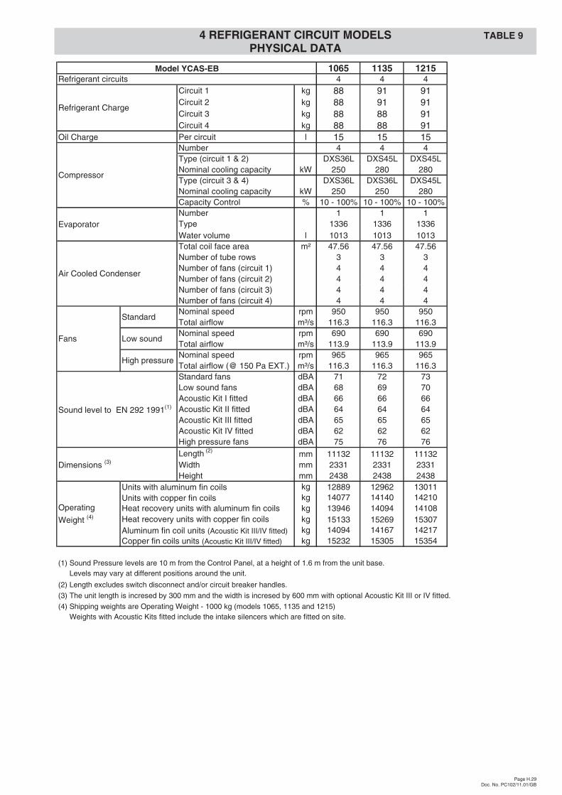
0685 0775 0835 0905 0965Refrigerant circuits 3 3 3 3 3
Circuit 1 kg 78 88 91 91 99Circuit 2 kg 78 88 88 91 99Circuit 3 kg 91 88 88 91 99
Oil Charge Per circuit l 15 15 15 15 15Number 3 3 3 3 3Type (circuit 1) DXS24L DXS36L DXS45L DXS45L DXS45LNominal cooling capacity kW 190 250 280 280 280Type (circuit 2) DXS24L DXS36L DXS36L DXS45L DXS45LNominal cooling capacity kW 190 250 250 280 280Type (circuit 3) DXS45L DXS36L DXS36L DXS45L DXS45LNominal cooling capacity kW 280 250 250 280 280Capacity Control % 10 - 100% 10 - 100% 10 - 100% 10 - 100% 10 - 100%Number 1 1 1 1 1Type 1224 1252 1252 1252 1252Water volume l 762 914 914 914 914Total coil face area m² 29.73 35.67 35.67 35.67 47.56Number of tube rows 3 3 3 3 3Number of fans (circuit 1) 3 4 4 4 5Number of fans (circuit 2) 3 4 4 4 5Number of fans (circuit 3) 4 4 4 4 6Nominal speed rpm 950 950 950 950 950Total airflow m³/s 72.7 87.2 87.2 87.2 116.3Nominal speed rpm 690 690 690 690 690Total airflow m³/s 71.2 85.5 85.5 85.5 113.9Nominal speed rpm 965 965 965 965 965Total airflow (@ 150 Pa EXT.) m³/s 72.7 87.2 87.2 87.2 116.3Standard fans dBA 70 70 70 71 72Low sound fans dBA 67 67 68 69 70Acoustic Kit I fitted dBA 64 65 65 65 66Acoustic Kit II fitted dBA 62 63 63 63 64Acoustic Kit III fitted dBA 63 64 64 64 65Acoustic Kit IV fitted dBA 60 60 60 60 60High pressure fans dBA 74 74 74 75 76Length (2) mm 7474 8694 8694 8694 11132Width mm 2331 2331 2331 2331 2331Height mm 2438 2438 2438 2438 2438
Units with aluminum fin coils kg 9089 9826 9915 9995 10746Units with copper fin coils kg 9783 10683 10772 10852 11847
kg N/A N/A N/A N/A N/Akg N/A N/A N/A N/A N/A
Aluminum fin coil units (Acoustic Kit III/IV fitted) kg 9879 10752 10841 10921 11952kg 10573 11609 11698 11778 13046
(1) Sound Pressure levels are 10 m from the Control Panel, at a height of 1.6 m from the unit base.(1) Levels may vary at different positions around the unit.
(2) Length excludes switch disconnect and/or circuit breaker handles.
(3) The unit length is incresed by 300 mm and the width is incresed by 600 mm with optional Acoustic Kit III or IV fitted.
(4) Shipping weights are Operating Weight - 750 kg (model 0685) or Operating Weight - 900 kg (models 0775, 0835, 0905 and 0965).(4) Weights with Acoustic Kits fitted include the intake silencers which are fitted on site.
Heat recovery units with aluminum fin coils
Evaporator
Air Cooled Condenser
Fans
Standard
Copper fin coils units (Acoustic Kit III/IV fitted)
Model YCAS-EB
Low sound
High pressure
Sound level to EN 292 1991(1)
Heat recovery units with copper fin coilsOperating
Weight (4)
Dimensions (3)
Refrigerant Charge
Compressor
TABLE 9 3 REFRIGERANT CIRCUIT MODELSPHYSICAL DATA
0
5
25
75
95
100
0
5
25
75
95
100
0
5
25
75
95
100
0
5
25
75
95
100
Page H.29Doc. No. PC102/11.01/GB
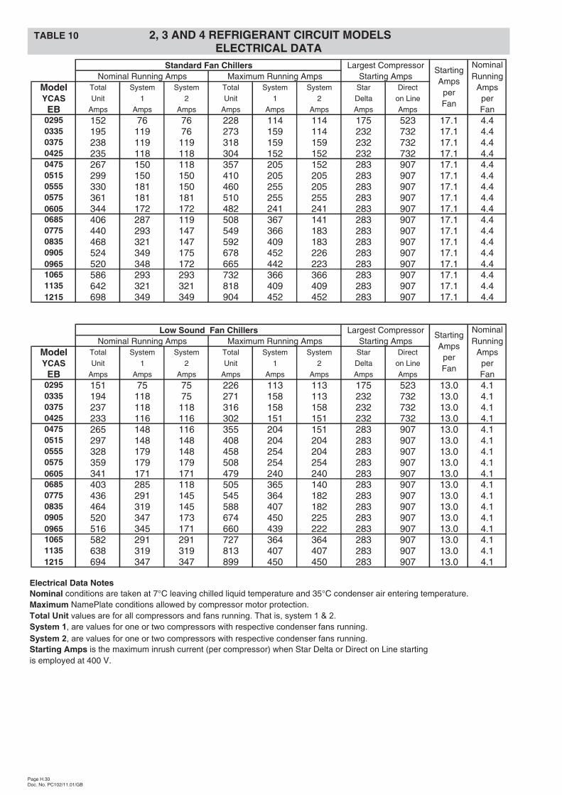
1065 1135 1215Refrigerant circuits 4 4 4
Circuit 1 kg 88 91 91Circuit 2 kg 88 91 91Circuit 3 kg 88 88 91Circuit 4 kg 88 88 91
Oil Charge Per circuit l 15 15 15Number 4 4 4Type (circuit 1 & 2) DXS36L DXS45L DXS45LNominal cooling capacity kW 250 280 280Type (circuit 3 & 4) DXS36L DXS36L DXS45LNominal cooling capacity kW 250 250 280Capacity Control % 10 - 100% 10 - 100% 10 - 100%Number 1 1 1Type 1336 1336 1336Water volume l 1013 1013 1013Total coil face area m² 47.56 47.56 47.56Number of tube rows 3 3 3Number of fans (circuit 1) 4 4 4Number of fans (circuit 2) 4 4 4Number of fans (circuit 3) 4 4 4Number of fans (circuit 4) 4 4 4Nominal speed rpm 950 950 950Total airflow m³/s 116.3 116.3 116.3Nominal speed rpm 690 690 690Total airflow m³/s 113.9 113.9 113.9Nominal speed rpm 965 965 965Total airflow (@ 150 Pa EXT.) m³/s 116.3 116.3 116.3Standard fans dBA 71 72 73Low sound fans dBA 68 69 70Acoustic Kit I fitted dBA 66 66 66Acoustic Kit II fitted dBA 64 64 64Acoustic Kit III fitted dBA 65 65 65Acoustic Kit IV fitted dBA 62 62 62High pressure fans dBA 75 76 76Length (2) mm 11132 11132 11132Width mm 2331 2331 2331Height mm 2438 2438 2438
Units with aluminum fin coils kg 12889 12962 13011Units with copper fin coils kg 14077 14140 14210
kg 13946 14094 14108kg 15133 15269 15307
Aluminum fin coil units (Acoustic Kit III/IV fitted) kg 14094 14167 14217kg 15232 15305 15354
(1) Sound Pressure levels are 10 m from the Control Panel, at a height of 1.6 m from the unit base.(1) Levels may vary at different positions around the unit.
(2) Length excludes switch disconnect and/or circuit breaker handles.
(3) The unit length is incresed by 300 mm and the width is incresed by 600 mm with optional Acoustic Kit III or IV fitted.
(4) Shipping weights are Operating Weight - 1000 kg (models 1065, 1135 and 1215)(4) Weights with Acoustic Kits fitted include the intake silencers which are fitted on site.
Copper fin coils units (Acoustic Kit III/IV fitted)
Fans
Standard
Sound level to EN 292 1991(1)
High pressure
Low sound
Operating
Weight (4)
Dimensions (3)
Heat recovery units with aluminum fin coilsHeat recovery units with copper fin coils
Air Cooled Condenser
Model YCAS-EB
Evaporator
Compressor
Refrigerant Charge
4 REFRIGERANT CIRCUIT MODELS TABLE 9PHYSICAL DATA
0
5
25
75
95
100
0
5
25
75
95
100
0
5
25
75
95
100
0
5
25
75
95
100
Page H.30Doc. No. PC102/11.01/GB
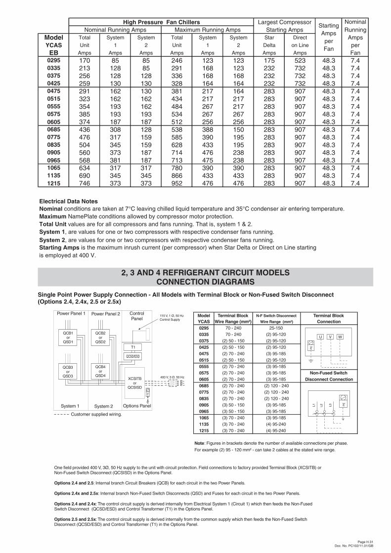
Standard Fan Chillers Largest Compressor NominalNominal Running Amps Maximum Running Amps Starting Amps Running
Model Total System System Total System System Star Direct AmpsYCAS Unit 1 2 Unit 1 2 Delta on Line per
EB Amps Amps Amps Amps Amps Amps Amps Amps Fan0295 152 76 76 228 114 114 175 523 17.1 4.40335 195 119 76 273 159 114 232 732 17.1 4.40375 238 119 119 318 159 159 232 732 17.1 4.40425 235 118 118 304 152 152 232 732 17.1 4.40475 267 150 118 357 205 152 283 907 17.1 4.40515 299 150 150 410 205 205 283 907 17.1 4.40555 330 181 150 460 255 205 283 907 17.1 4.40575 361 181 181 510 255 255 283 907 17.1 4.40605 344 172 172 482 241 241 283 907 17.1 4.40685 406 287 119 508 367 141 283 907 17.1 4.40775 440 293 147 549 366 183 283 907 17.1 4.40835 468 321 147 592 409 183 283 907 17.1 4.40905 524 349 175 678 452 226 283 907 17.1 4.40965 520 348 172 665 442 223 283 907 17.1 4.41065 586 293 293 732 366 366 283 907 17.1 4.41135 642 321 321 818 409 409 283 907 17.1 4.41215 698 349 349 904 452 452 283 907 17.1 4.4
Low Sound Fan Chillers Largest Compressor NominalNominal Running Amps Maximum Running Amps Starting Amps Running
Model Total System System Total System System Star Direct AmpsYCAS Unit 1 2 Unit 1 2 Delta on Line per
EB Amps Amps Amps Amps Amps Amps Amps Amps Fan0295 151 75 75 226 113 113 175 523 13.0 4.10335 194 118 75 271 158 113 232 732 13.0 4.10375 237 118 118 316 158 158 232 732 13.0 4.10425 233 116 116 302 151 151 232 732 13.0 4.10475 265 148 116 355 204 151 283 907 13.0 4.10515 297 148 148 408 204 204 283 907 13.0 4.10555 328 179 148 458 254 204 283 907 13.0 4.10575 359 179 179 508 254 254 283 907 13.0 4.10605 341 171 171 479 240 240 283 907 13.0 4.10685 403 285 118 505 365 140 283 907 13.0 4.10775 436 291 145 545 364 182 283 907 13.0 4.10835 464 319 145 588 407 182 283 907 13.0 4.10905 520 347 173 674 450 225 283 907 13.0 4.10965 516 345 171 660 439 222 283 907 13.0 4.11065 582 291 291 727 364 364 283 907 13.0 4.11135 638 319 319 813 407 407 283 907 13.0 4.11215 694 347 347 899 450 450 283 907 13.0 4.1
StartingAmps
perFan
StartingAmps
perFan
TABLE 10 2, 3 AND 4 REFRIGERANT CIRCUIT MODELSELECTRICAL DATA
Electrical Data NotesNominal conditions are taken at 7°C leaving chilled liquid temperature and 35°C condenser air entering temperature.Maximum NamePlate conditions allowed by compressor motor protection.Total Unit values are for all compressors and fans running. That is, system 1 & 2.
System 1, are values for one or two compressors with respective condenser fans running.
System 2, are values for one or two compressors with respective condenser fans running.
Starting Amps is the maximum inrush current (per compressor) when Star Delta or Direct on Line startingis employed at 400 V.
0
5
25
75
95
100
0
5
25
75
95
100
0
5
25
75
95
100
0
5
25
75
95
100
2, 3 AND 4 REFRIGERANT CIRCUIT MODELSCONNECTION DIAGRAMS
Page H.31Doc. No. PC102/11.01/GB
High Pressure Fan Chillers Largest Compressor NominalNominal Running Amps Maximum Running Amps Starting Amps Running
Model Total System System Total System System Star Direct AmpsYCAS Unit 1 2 Unit 1 2 Delta on Line per
EB Amps Amps Amps Amps Amps Amps Amps Amps Fan0295 170 85 85 246 123 123 175 523 48.3 7.40335 213 128 85 291 168 123 232 732 48.3 7.40375 256 128 128 336 168 168 232 732 48.3 7.40425 259 130 130 328 164 164 232 732 48.3 7.40475 291 162 130 381 217 164 283 907 48.3 7.40515 323 162 162 434 217 217 283 907 48.3 7.40555 354 193 162 484 267 217 283 907 48.3 7.40575 385 193 193 534 267 267 283 907 48.3 7.40605 374 187 187 512 256 256 283 907 48.3 7.40685 436 308 128 538 388 150 283 907 48.3 7.40775 476 317 159 585 390 195 283 907 48.3 7.40835 504 345 159 628 433 195 283 907 48.3 7.40905 560 373 187 714 476 238 283 907 48.3 7.40965 568 381 187 713 475 238 283 907 48.3 7.41065 634 317 317 780 390 390 283 907 48.3 7.41135 690 345 345 866 433 433 283 907 48.3 7.41215 746 373 373 952 476 476 283 907 48.3 7.4
StartingAmps
perFan
Electrical Data NotesNominal conditions are taken at 7°C leaving chilled liquid temperature and 35°C condenser air entering temperature.Maximum NamePlate conditions allowed by compressor motor protection.Total Unit values are for all compressors and fans running. That is, system 1 & 2.
System 1, are values for one or two compressors with respective condenser fans running.
System 2, are values for one or two compressors with respective condenser fans running.
Starting Amps is the maximum inrush current (per compressor) when Star Delta or Direct on Line startingis employed at 400 V.
Model Terminal Block N-F Switch Disconnect Terminal BlockYCAS Wire Range (mm²) Wire Range (mm²) Connection0295 70 - 240 25-150
0335 70 - 240 (2) 95-120
0375 (2) 50 - 150 (2) 95-120
0425 (2) 50 - 150 (2) 95-120
0475 (2) 70 - 240 (3) 95-185
0515 (2) 50 - 150 (2) 95-120
0555 (2) 70 - 240 (3) 95-185
0575 (2) 70 - 240 (3) 95-185 Non-Fused Switch0605 (2) 70 - 240 (3) 95-185 Disconnect Connection0685 (2) 70 - 240 (2) 120 - 240
0775 (2) 70 - 240 (2) 120 - 240
0835 (2) 70 - 240 (2) 120 - 240
0905 (3) 50 - 150 (3) 95-185
0965 (3) 50 - 150 (3) 95-185
1065 (3) 70 - 240 (3) 95-185
1135 (3) 70 - 240 (4) 95-240
1215 (3) 70 - 240 (4) 95-240
Note: Figures in brackets denote the number of available connections per phase.
For example (2) 95 - 120 mm² - can take 2 cables at the stated wire range.
XCSITBor
QCSISD
PE
Options Panel
QCB4or
QSD4
QCB3or
QSD3
QCB2or
QSD2
System 2System 1
QCB1or
QSD1
Customer supplied wiring.
400 V, 3 Ø, 50 Hz
ControlPanel
Power Panel 1 Power Panel 2 115 V, 1 Ø, 50 HzControl Supply
T1
QCSD/ESD
One field provided 400 V, 3Ø, 50 Hz supply to the unit with circuit protection. Field connections to factory provided Terminal Block (XCSITB) orNon-Fused Disconnect (QCSISD) in the Options Panel.Switch
: Internal branch Circuit Breakers (QCB) for each circuit in the two Power Panels.
: Internal branch Non-Fused Switch Disconnects (QSD) and Fuses for each circuit in the two Power Panels.
: The control circuit supply is derived internally from Electrical System 1 (Circuit 1) which then feeds the Non-FusedSwitch Disconnect (QCSD/ESD) and Control Transformer (T1) in the Options Panel.
: The control circuit supply is derived internally from the common supply which then feeds the Non-Fused SwitchDisconnect (QCSD/ESD) and Control Transformer (T1) in the Options Panel.
Options 2.4 and 2.5
Options 2.4x and 2.5x
Options 2.4 and 2.4x
Options 2.5 and 2.5x
U V W
PE
PE
L1 L2 L3
Single Point Power Supply Connection - All Models with Terminal Block or Non-Fused Switch Disconnect(Options 2.4, 2.4x, 2.5 or 2.5x)
0
5
25
75
95
100
0
5
25
75
95
100
0
5
25
75
95
100
0
5
25
75
95
100
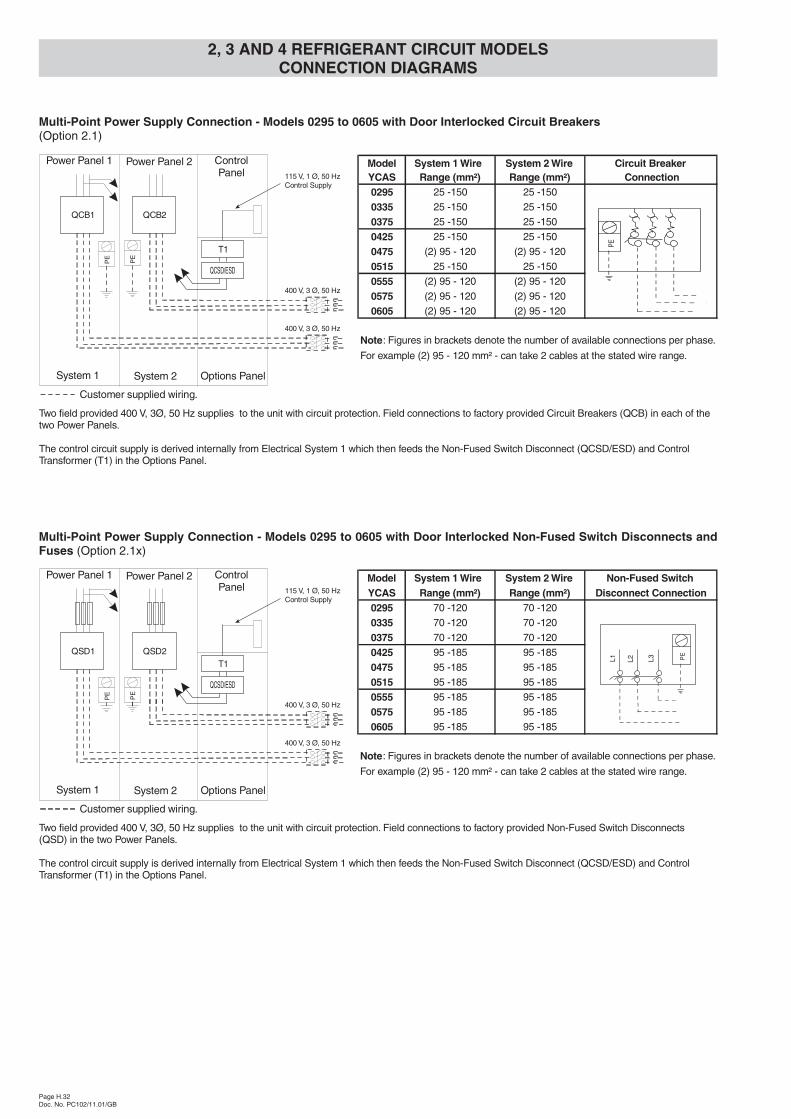
2, 3 AND 4 REFRIGERANT CIRCUIT MODELSCONNECTION DIAGRAMS
Page H.32Doc. No. PC102/11.01/GB
Model System 1 Wire System 2 Wire Non-Fused SwitchYCAS Range (mm²) Range (mm²) Disconnect Connection0295 70 -120 70 -120
0335 70 -120 70 -120
0375 70 -120 70 -120
0425 95 -185 95 -185
0475 95 -185 95 -185
0515 95 -185 95 -185
0555 95 -185 95 -185
0575 95 -185 95 -185
0605 95 -185 95 -185
Note: Figures in brackets denote the number of available connections per phase.
For example (2) 95 - 120 mm² - can take 2 cables at the stated wire range.
Options PanelSystem 2System 1
400 V, 3 Ø, 50 Hz
400 V, 3 Ø, 50 Hz
PE
PE
QSD1
Customer supplied wiring.
ControlPanel
Power Panel 1 Power Panel 2115 V, 1 Ø, 50 HzControl Supply
T1
QCSD/ESD
Two field provided 400 V, 3Ø, 50 Hz supplies to the unit with circuit protection. Field connections to factory provided Non-Fused Switch Disconnects(QSD) in the two Power Panels.
The control circuit supply is derived internally from Electrical System 1 which then feeds the Non-Fused Disconnect (QCSD/ESD) and ControlTransformer (T1) in the Options Panel.
Switch
QSD2
PE
L1 L2 L3
Multi-Point Power Supply Connection - Models 0295 to 0605 with Door Interlocked Non-Fused Switch Disconnects andFuses (Option 2.1x)
Model System 1 Wire System 2 Wire Circuit BreakerYCAS Range (mm²) Range (mm²) Connection0295 25 -150 25 -150
0335 25 -150 25 -150
0375 25 -150 25 -150
0425 25 -150 25 -150
0475 (2) 95 - 120 (2) 95 - 120
0515 25 -150 25 -150
0555 (2) 95 - 120 (2) 95 - 120
0575 (2) 95 - 120 (2) 95 - 120
0605 (2) 95 - 120 (2) 95 - 120
Note: Figures in brackets denote the number of available connections per phase.
For example (2) 95 - 120 mm² - can take 2 cables at the stated wire range.
Options PanelSystem 2System 1
400 V, 3 Ø, 50 Hz
400 V, 3 Ø, 50 Hz
PE
PE
QCB1
Customer supplied wiring.
ControlPanel
Power Panel 1 Power Panel 2115 V, 1 Ø, 50 HzControl Supply
T1
QCSD/ESD
PE
QCB2
Two field provided 400 V, 3Ø, 50 Hz supplies to the unit with circuit protection. Field connections to factory provided Circuit Breakers (QCB) in each of thetwo Power Panels.
The control circuit supply is derived internally from Electrical System 1 which then feeds the Non-Fused Disconnect (QCSD/ESD) and ControlTransformer (T1) in the Options Panel.
Switch
Multi-Point Power Supply Connection - Models 0295 to 0605 with Door Interlocked Circuit Breakers(Option 2.1)
0
5
25
75
95
100
0
5
25
75
95
100
0
5
25
75
95
100
0
5
25
75
95
100

2, 3 AND 4 REFRIGERANT CIRCUIT MODELSCONNECTION DIAGRAMS
Page H.33Doc. No. PC102/11.01/GB
Model System 1 Wire System 2 Wire Terminal BlockYCAS Range (mm²) Range (mm²) Connection0685 (2) 35 - 95 35 - 95
0775 (2) 35 - 95 35 - 95
0835 (2) 50 - 150 35 - 95
0905 (2) 50 - 150 50 - 150
0965 (2) 50 - 150 50 - 150
1065 (2) 35 - 95 (2) 35 - 95
1135 (2) 50 - 150 (2) 50 - 150
1215 (2) 50 - 150 (2) 50 - 150
Note: Figures in brackets denote the number of available connections per phase.
For example (2) 95 - 120 mm² - can take 2 cables at the stated wire range.
QCB4or
QSD4
QCB3or
QSD3
OptionsPanelSystem 2System 1
PE
QCB1or
QSD1
Customer supplied wiring.
XCSITB1
PE
400 V, 3 Ø, 50 Hz
400 V, 3 Ø, 50 Hz
ControlPanel
Power Panel 1 Power Panel 2 115 V, 1 Ø, 50 HzControl Supply
T1
QCSD/ESD
QCB2or
QSD2
XCSITB2
U V W
PE
Two field provided 400 V, 3Ø, 50 Hz supplies to the unit with circuit protection. Field connections to factory provided Terminal Blocks (XCSITB)in the Options Panel.
: Internal branch Circuit Breakers (QCB) for each circuit in the two Power Panels.
The control circuit supply is derived internally from Electrical System 1 (Circuit 1) which then feeds the Non-Fused Disconnect(QCSD/ESD) and Control Transformer (T1) in the Options Panel.
Option 2.2
Option 2.2x: Internal branch Non-Fused Switch Disconnects (QSD) and Fuses for each circuit in the two Power Panels.
Switch
Multi-Point Power Supply Connection - Models 0685 to 1215 with Terminal Blocks(Options 2.2 and 2.2x)
Model System 1 System 2 Non-Fused SwitchYCAS Wire Range Wire Range Disconnect Connection0685 (2) 95-120 35 - 95
0775 (2) 95-120 25 - 150
0835 (2) 120 - 240 25 - 150
0905 (2) 120 - 240 25 - 150
0965 (2) 120 - 240 25 - 150
1065 (2) 95-120 (2) 95-120
1135 (2) 120 - 240 (2) 120 - 240
1215 (2) 120 - 240 (2) 120 - 240
Note: Figures in brackets denote the number of available connections per phase.
For example (2) 95 - 120 mm² - can take 2 cables at the stated wire range.
QCB4or
QSD4
QCB3or
QSD3
OptionsPanelSystem 2System 1
PE
QCB1or
QSD1
Customer supplied wiring.
QCSISD1
PE
400 V, 3 Ø, 50 Hz
400 V, 3 Ø, 50 Hz
ControlPanel
Power Panel 1 Power Panel 2 115 V, 1 Ø, 50 HzControl Supply
T1
QCSD/ESD
QCB2or
QSD2
QCSISD2
Two field provided 400 V, 3Ø, 50 Hz supplies to the unit with circuit protection. Field connections to factory provided Non-Fused(QCSISD) in the Options Panel.
: Internal branch Circuit Breakers (QCB) for each circuit in the two Power Panels.
The control circuit supply is derived internally from Electrical System 1 (Circuit 1) which then feeds the Non-Fused Disconnect (QCSD/ESD) andControl Transformer (T1) in the Options Panel.
Switch Disconnects
: Internal branch Non-Fused Switch Disconnects (QSD) and Fuses for each circuit in the two Power Panels.
Switch
Option 2.3
Option 2.3x
PE
L1 L2 L3
Multi-Point Power Supply Connection - Models 0685 to 1215 with Non-Fused Switch Disconnects(Options 2.3 and 2.3x)
0
5
25
75
95
100
0
5
25
75
95
100
0
5
25
75
95
100
0
5
25
75
95
100

2, 3 AND 4 REFRIGERANT CIRCUIT MODELSCONNECTION DIAGRAMS
Page H.34Doc. No. PC102/11.01/GB
13
SF
1
QRESB
Link mustbe removed
1SA 2SA CRS 3SA 4SACLP
23 25 27 29 37 41
AMB
APB
AIOB
CONTROL PANEL
5 24 26 28 30 38 42
RU RP
XTBE
PWMT
13 13 1314 16 17 18
RRI
13
SF
1514
RRI1RRI2
2 Circuit Models only
XTBE
Customer Connection Diagram
AMB Microprocessor Board CLP Chilled Liquid Pump Start 1SA System 1 Alarm Contacts
AIOB Input/Output Board CRS Chiller Run 2SA System 2 Alarm Contacts
APB Power Board RU Current PWM 3SA System 3 Alarm Contacts
QRESB Remote Emergency Stop PWMT Temperature PWM 4SA System 4 Alarm Contacts
RRI Remote Run Interlock RRI1 Remote Run Interlock (Circuit 1) RRI2 Remote Run Interlock (Circuit 2)
SF Flow Switch RP Remote Print XTBE Ground Terminal
0
5
25
75
95
100
0
5
25
75
95
100
0
5
25
75
95
100
0
5
25
75
95
100

CLEARANCES (All Models)
Page H.35Doc. No. PC102/11.01/GB
3 m 2 m
1.3
m2
m
2 m
2m
2m
1.3
m
1.3 m
2m
2m
2 m
2 m 2 m
0
5
25
75
95
100
0
5
25
75
95
100
0
5
25
75
95
100
0
5
25
75
95
100

DIMENSIONS
Models 0295, 0335 and 0375
Page H.36Doc. No. PC102/11.01/GB
2321
1614 21342506
4499
191 6" WATER INLET6" WATER OUTLET
406
A
A
X
Y
0
0
0 0
0 0
1418 1380
229
711
120305
51
1981
914
POWER OPENING(BOTH SIDES)
953
806
32
32
2438
2235762
762
CONTROL ENTRY(12) 13CONDUIT K.O.'S
C
C
B B
191
178
51800
1067
51
GC
Z
X
GC
POWER ELEMENTSFOR SYS. #1
PO
WE
RPA
NE
L
CONTROL PANEL
POWER ELEMENTSFOR SYS.#2
VIEW C-C
VIEW B-B
CENTRE OF GRAVITY FROM ORIGIN
16 ØHOLES (TYP.)
MOUNTING
51 TYP.
MICRO-COMPUTERCONTROL CENTRE
SYS.#2COILS
SYS.#1COILS
POWER OPENING(178 WIDE x
533 HIGH)
EMERGENCY STOP/TRANSFORMERSERVICE SWITCH
VIEW A-A
62 (EDGE OFUNIT TO COOLERCONNECTION)
SYS.#1
OPTIONS PANEL
(2) 57 Ø RIGGINGHOLES (EACH SIDE)
SYS.#2
POWEROPENING
(533 HIGH)
CONTROLOPENING
(229 HIGH)
774
2279
Victualic ConnectionsØ 114 mm
250
Optional Heat Recovery Condenser Connections
Inlet Outlet
227.9456 25.0000
77.3780
2320
834
170
Optional Desuperheater Connections
Outlet InletVictualic Connections Ø 1½" (38 mm)
0
5
25
75
95
100
0
5
25
75
95
100
0
5
25
75
95
100
0
5
25
75
95
100

DIMENSIONS (continued)
Models 0425, 0475, 0515, 0555 and 0575
Page H.37Doc. No. PC102/11.01/GB
1624 3419
57182989
1981
914
953
2438
A
A191
51
2321
438
229
711
120305
51CONTROL ENTRY
(12) 13CONDUIT K.O.'S
C
C
B B
191
178
51800
1067
VIEW C-C
VIEW B-B
51 TYP.
MICRO-COMPUTERCONTROL CENTRE
SYS.#2COILS
SYS.#1COILS
POWER OPENING(178 WIDE x
533 HIGH)
EMERGENCY STOP/TRANSFORMERSERVICE SWITCH
VIEW A-A
49 (EDGE OFUNIT TO COOLERCONNECTION)
OPTIONS PANEL
POWEROPENING
(533 HIGH)
CONTROLOPENING
(229 HIGH)762
2235
762
GC
Z
X
GC
Y
X
806 1368 1368 1368
32
32
POWER ELEMENTSFOR SYS. #1
POWER ELEMENTSFOR SYS.#2
CONTROL PANEL
CENTRE OF GRAVITY FROM ORIGIN
16 Ø MOUNTINGHOLES (TYP.)
SYS.#1
8" WATER INLET 8" WATER OUTLET(2) 57 Ø RIGGINGHOLES (EACH SIDE)
PO
WE
RPA
NE
L
POWER OPENING(BOTH SIDES)
774
2279
Victualic ConnectionsØ 114 mm
250
Optional Heat Recovery Condenser Connections
Inlet Outlet
227.9456 25.0000
77.3780
2320
834
170
Optional Desuperheater Connections
Outlet InletVictualic Connections Ø 1½" (38 mm)
0
5
25
75
95
100
0
5
25
75
95
100
0
5
25
75
95
100
0
5
25
75
95
100

DIMENSIONS (continued)
Model 0605
Page H.38Doc. No. PC102/11.01/GB
806
Z
191A
1981
914
51
A
Y
2235762
762
6937
X
953
1624
2184
3419
1900
2438
1658
X
1658 1900
32
32
POWER OPENING(BOTH SIDES)
GC
8" WATER INLET
CENTRE OF GRAVITY FROM ORIGINGC
SYS.#1
CONTROLPANEL
POWERELEMENTS
FOR SYS.#2
POWERELEMENTS
FOR SYS. #1
PO
WE
RPA
NE
L
16 Ø MOUNTINGHOLES (TYP.)
(3) 57 Ø RIGGINGHOLES (EACH SIDE)
8" WATER OUTLET
SYS.#2
2321
438
229
711
120305
51CONTROL ENTRY
(12) 13CONDUIT K.O.'S
C
C
B B
191
178
51800
1067
VIEW C-C
VIEW B-B
51 TYP.
MICRO-COMPUTERCONTROL CENTRE
SYS.#2COILS
SYS.#1COILS
POWER OPENING(178 WIDE x
533 HIGH)
EMERGENCY STOP/TRANSFORMERSERVICE SWITCH
VIEW A-A
49 (EDGE OFUNIT TO COOLERCONNECTION)
OPTIONS PANEL
POWEROPENING
(533 HIGH)
CONTROLOPENING
(229 HIGH)
774
2279
Victualic ConnectionsØ 114 mm
250
Optional Heat Recovery Condenser Connections
Inlet Outlet
227.9456 25.0000
77.3780
2320
834
170
Optional Desuperheater Connections
Outlet InletVictualic Connections Ø 1½" (38 mm)
0
5
25
75
95
100
0
5
25
75
95
100
0
5
25
75
95
100
0
5
25
75
95
100

DIMENSIONS (continued)
Model 0685
Page H.39Doc. No. PC102/11.01/GB
46(E
DG
EO
FB
AS
ETO
CO
OLE
RC
ON
NE
CT
ION
)
MIC
RO
-CO
MP
UT
ER
CO
NT
RO
LC
EN
TR
E
3424
3251
2277
7474
191
10"W
ATE
RO
UT
LET
10"W
ATE
RIN
LET
POWERPANEL
540
A A
(3)
57Ø
RIG
GIN
GH
OLE
S(E
AC
HS
IDE
)
CX
Y
VIE
WB
-B22
951
TY
P.
711
120
305
51
1981
914
1727
G C G
Z
X
3232
2438
2235
762
762
OP
TIO
NS
PAN
EL
VIE
WC
-C
51
CO
NT
RO
LE
NT
RY
(12)
13C
ON
DU
ITK
.O.'S
CO
NT
RO
LO
PE
NIN
G(2
29H
IGH
)
PO
WE
RO
PE
NIN
G(5
33H
IGH
)
C C
51
BB
191
178
800
1067
1841
PO
WE
RO
PE
NIN
G
806
1453
1453
1453
1229
SY
S. 1
SY
S. 3
SY
S.2
PO
WE
RE
LEM
EN
TS
FO
RS
YS
. 2
PO
WE
RE
LEM
EN
TS
FO
RS
YS
. 1&
3
CO
NT
RO
LPA
NE
L
SY
S.1
&2
SY
S.3
16Ø
MO
UN
TIN
GH
OLE
S(T
YP.
)
VIE
WA
-A23
3122
3548
EM
ER
GE
NC
YS
TOP
/T
RA
NS
FO
RM
ER
SE
RV
ICE
SW
ITC
H
CE
NT
RE
OF
GR
AVIT
YF
RO
MO
RIG
IN
0
5
25
75
95
100
0
5
25
75
95
100
0
5
25
75
95
100
0
5
25
75
95
100

DIMENSIONS (continued)
Models 0775, 0835 and 0905
Page H.40Doc. No. PC102/11.01/GB
3992
3607
8694
POWERPANEL
(4)
57Ø
RIG
GIN
GH
OLE
S(E
AC
HS
IDE
)
2277
1981
914
1727
C G
Z
X
3232
2235
762
762
A A
OP
TIO
NS
PAN
EL
C C
VIE
WB
-B
120
51
229
51T
YP.
711
305
191
PO
WE
RO
PE
NIN
G
2438
10"W
ATE
RIN
LET
540
1713
1614
BB
VIE
WC
-C19
1
178
5180
0
1067
51
806
1453
1453
1453
1229
1400
CO
NT
RO
LPA
NE
L
SY
S. 1
C GX
Y
SY
S. 3
SY
S.1
&2
SY
S.3
VIE
WA
-A23
3122
3548
SY
S. 2
110
(ED
GE
OF
BA
SE
TOC
OO
LER
CO
NN
EC
TIO
N)
MIC
RO
-C
OM
PU
TE
RC
ON
TR
OL
CE
NT
RE
CO
NT
RO
LE
NT
RY
(12)
13C
ON
DU
ITK
.O.'S
CO
NT
RO
LO
PE
NIN
G(5
33H
IGH
)
PO
WE
RO
PE
NIN
G(2
29H
IGH
)P
OW
ER
ELE
ME
NT
SF
OR
SY
S. 2
PO
WE
RE
LEM
EN
TS
FO
RS
YS
. 1&
3
16Ø
MO
UN
TIN
GH
OLE
S(T
YP.
)
EM
ER
GE
NC
YS
TOP
/T
RA
NS
FO
RM
ER
SE
RV
ICE
SW
ITC
H
CE
NT
RE
OF
GR
AVIT
YF
RO
MO
RIG
IN
10"W
ATE
RO
UT
LET
0
5
25
75
95
100
0
5
25
75
95
100
0
5
25
75
95
100
0
5
25
75
95
100

DIMENSIONS (continued)
Model 0965
Page H.41Doc. No. PC102/11.01/GB
110
(ED
GE
OF
BA
SE
TOC
OO
LER
CO
NN
EC
TIO
N)
2235
3992
3607
2277
2932
1113
2
10"W
ATE
RIN
LET
10"W
ATE
RO
UT
LET
POWERPANEL
(4)
57Ø
RIG
GIN
GH
OLE
S(E
AC
HS
IDE
)
1981
914
1727
C G
Z
X
32 32
762
762
A A
OP
TIO
NS
PAN
EL
MIC
RO
-CO
MP
UT
ER
CO
NT
RO
LC
EN
TR
E
C C
VIE
WB
-B
120
51C
ON
TR
OL
EN
TR
Y(1
2)13
CO
ND
UIT
K.O
.'S
229
51T
YP.
711
305
191
PO
WE
RO
PE
NIN
G
2438
540
SY
S. 1
&2
SY
S. 3
2833
BB
VIE
WC
-C19
1
178
PO
WE
RO
PE
NIN
G(5
33H
IGH
)
CO
NT
RO
LO
PE
NIN
G(2
29H
IGH
) 5180
0
1067
51
1422
1413
1422
1431
1453
1453
806
PO
WE
RE
LEM
EN
TS
FO
RS
YS
. 2
PO
WE
RE
LEM
EN
TS
FO
RS
YS
. 1&
3S
YS
. 1
SY
S. 2
SY
S. 3
Y
GCX
CO
NT
RO
LPA
NE
L
16Ø
MO
UN
TIN
GH
OLE
S(T
YP.
)
1453
VIE
WA
-A23
3122
3548
EM
ER
GE
NC
YS
TOP
/T
RA
NS
FO
RM
ER
SE
RV
ICE
SW
ITC
H
CE
NT
RE
OF
GR
AVIT
YF
RO
MO
RIG
IN
0
5
25
75
95
100
0
5
25
75
95
100
0
5
25
75
95
100
0
5
25
75
95
100
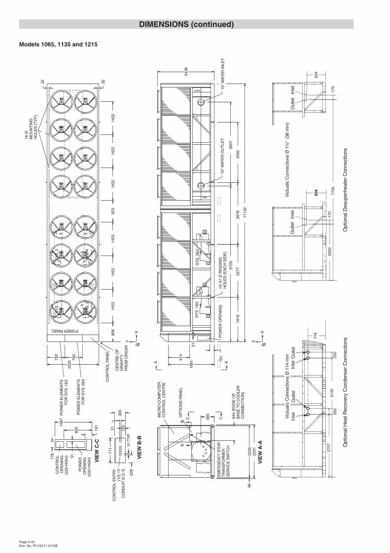
DIMENSIONS (continued)
Models 1065, 1135 and 1215
Page H.42Doc. No. PC102/11.01/GB
644
(ED
GE
OF
BA
SE
TOC
OO
LER
CO
NN
EC
TIO
N)
6720
3607
1113
2
10"W
ATE
RO
UT
LET
10"W
ATE
RIN
LET
POWERPANEL(4
)57
ØR
IGG
ING
HO
LES
(EA
CH
SID
E)
2277
1981
914
1918
C G
Z
X
3232
2235
762
762
A A
EM
ER
GE
NC
YS
TOP
/TR
AN
SFO
RM
ER
SE
RV
ICE
SW
ITC
H
OP
TIO
NS
PAN
EL
MIC
RO
-CO
MP
UT
ER
CO
NT
RO
LC
EN
TR
E
C C
VIE
WB
-B
120
51C
ON
TR
OL
EN
TR
Y(1
2)13
CO
ND
UIT
K.O
.'S
229
51T
YP.
711
305
191
PO
WE
RO
PE
NIN
G
2438
2678
2592
BB
VIE
WC
-C19
1
178
PO
WE
RO
PE
NIN
G(5
33H
IGH
)
CO
NT
RO
LO
PE
NIN
G(2
29H
IGH
) 5180
0
1067
51
806
1453
923
1453
1453
1422
1422
1422
PO
WE
RE
LEM
EN
TS
FO
RS
YS
. 2&
4
PO
WE
RE
LEM
EN
TS
FO
RS
YS
. 1&
3 CO
NT
RO
LPA
NE
L
SY
S. 1
SY
S. 2
SY
S. 4
SY
S. 3
GCX
Y
SY
S. 1
&2
SY
S. 3
&4
16Ø
MO
UN
TIN
GH
OLE
S(T
YP.
)
565
VIE
WA
-A23
3122
3548
CE
NT
RE
OF
GR
AVIT
YF
RO
MO
RIG
IN
Opt
iona
l Hea
tRec
over
yC
onde
nser
Con
nect
ions
2707
250
5145
774
Inle
tIn
let
Out
let
Out
let
Vic
tual
icC
onne
ctio
nsØ
114
mm 25
023
20
834
7734
170
834
170
834
Opt
iona
l Des
uper
heat
erC
onne
ctio
ns
Out
let
Inle
tO
utle
tIn
let
Vic
tual
icC
onne
ctio
nsØ
1½"
(38
mm
)
0
5
25
75
95
100
0
5
25
75
95
100
0
5
25
75
95
100
0
5
25
75
95
100


![iPBook ITA 0575 Hodgson William Hope - L'Orrore Del Mare [by CDX]](https://img.pdfslide.us/doc/110x75/557213d3497959fc0b931bfb/ipbook-ita-0575-hodgson-william-hope-lorrore-del-mare-by-cdx.jpg)