Embed Size (px)
Citation preview

AV SURROUND RECEIVER
AVR-589Owner’s Manual
Manuel de l’Utilisateur

n SAFETY PRECAUTIONS
CAUTIONRISK OF ELECTRIC SHOCK
DO NOT OPEN
CAUTION:TO REDUCE THE RISK OF ELECTRIC SHOCK, DO NOT REMOVE COVER (OR BACK). NO USER-SERVICEABLE PARTS INSIDE. REFER SERVICING TO QUALIFIED SERVICE PERSONNEL.
The lightning flash with arrowhead symbol, within an equilateral triangle, is intended to alert the user to the presence of uninsulated “dangerous voltage” within the product’s enclosure that may be of sufficient magnitude to constitute a risk of electric shock to persons.
The exclamation point within an equilateral triangle is intended to alert the user to the presence of important operating and maintenance (servicing) instructions in the literature accompanying the appliance.
WARNING:TO REDUCE THE RISK OF FIRE OR ELECTRIC SHOCK, DO NOT EXPOSE THIS APPLIANCE TO RAIN OR MOISTURE.
SAFETY INSTRUCTIONS1. Read Instructions – All the safety and operating instructions should be read
before the product is operated.2. Retain Instructions – The safety and operating instructions should be
retained for future reference.3. Heed Warnings – All warnings on the product and in the operating
instructions should be adhered to.4. Follow Instructions – All operating and use instructions should be followed.5. Cleaning – Unplug this product from the wall outlet before cleaning. Do not
use liquid cleaners or aerosol cleaners.6. Attachments – Do not use attachments not recommended by the product
manufacturer as they may cause hazards.7. Water and Moisture – Do not use this product near water – for example,
near a bath tub, wash bowl, kitchen sink, or laundry tub; in a wet basement; or near a swimming pool; and the like.
8. Accessories – Do not place this product on an unstable cart, stand, tripod, bracket, or table. The product may fall, causing serious injury to a child or adult, and serious damage to the product. Use only with a cart, stand, tripod, bracket, or table recommended by the manufacturer, or sold with the product. Any mounting of the product should
follow the manufacturer’s instructions, and should use a mounting accessory recommended by the manufacturer.9. A product and cart combination should be moved with care. Quick stops, excessive force, and uneven surfaces may cause the product and cart combination to overturn.10. Ventilation – Slots and openings in the cabinet are provided for ventilation
and to ensure reliable operation of the product and to protect it from overheating, and these openings must not be blocked or covered. The openings should never be blocked by placing the product on a bed, sofa, rug, or other similar surface. This product should not be placed in a built-in installation such as a bookcase or rack unless proper ventilation is provided or the manufacturer’s instructions have been adhered to.
11. Power Sources – This product should be operated only from the type of power source indicated on the marking label. If you are not sure of the type of power supply to your home, consult your product dealer or local power company. For products intended to operate from battery power, or other sources, refer to the operating instructions.
12. Grounding or Polarization – This product may be equipped with a polarized alternating-current line plug (a plug having one blade wider than the other). This plug will fit into the power outlet only one way. This is a safety feature. If you are unable to insert the plug fully into the outlet, try reversing the plug. If the plug should still fail to fit, contact your electrician to replace your obsolete outlet. Do not defeat the safety purpose of the polarized plug.
13. Power-Cord Protection – Power-supply cords should be routed so that they are not likely to be walked on or pinched by items placed upon or against them, paying particular attention to cords at plugs, convenience receptacles, and the point where they exit from the product.
15. Outdoor Antenna Grounding – If an outside antenna or cable system is connected to the product, be sure the antenna or cable system is grounded so as to provide some protection against voltage surges and built-up static charges. Article 810 of the National Electrical Code, ANSI/NFPA 70, provides information with regard to proper grounding of the mast and supporting structure, grounding of the lead-in wire to an antenna discharge unit, size of grounding conductors, location of antenna-discharge unit, connection to grounding electrodes, and requirements for the grounding electrode. See Figure A.
16. Lightning – For added protection for this product during a lightning storm, or when it is left unattended and unused for long periods of time, unplug it from the wall outlet and disconnect the antenna or cable system. This will prevent damage to the product due to lightning and power-line surges.
17. Power Lines – An outside antenna system should not be located in the vicinity of overhead power lines or other electric light or power circuits, or where it can fall into such power lines or circuits. When installing an outside antenna system, extreme care should be taken to keep from touching such power lines or circuits as contact with them might be fatal.
18. Overloading – Do not overload wall outlets, extension cords, or integral convenience receptacles as this can result in a risk of fire or electric shock.
19. Object and Liquid Entry – Never push objects of any kind into this product through openings as they may touch dangerous voltage points or short-out parts that could result in a fire or electric shock. Never spill liquid of any kind on the product.
20. Servicing – Do not attempt to service this product yourself as opening or removing covers may expose you to dangerous voltage or other hazards. Refer all servicing to qualified service personnel.
21. Damage Requiring Service – Unplug this product from the wall outlet and refer servicing to qualified service personnel under the following conditions:
a) When the power-supply cord or plug is damaged, b) If liquid has been spilled, or objects have fallen into the product, c) If the product has been exposed to rain or water, d) If the product does not operate normally by following the operating
instructions. Adjust only those controls that are covered by the operating instructions as an improper adjustment of other controls may result in damage and will often require extensive work by a qualified technician to restore the product to its normal operation,
e) If the product has been dropped or damaged in any way, and f) When the product exhibits a distinct change in performance – this
indicates a need for service.22. Replacement Parts – When replacement parts are required, be sure the
service technician has used replacement parts specified by the manufacturer or have the same characteristics as the original part. Unauthorized substitutions may result in fire, electric shock, or other hazards.
23. Safety Check – Upon completion of any service or repairs to this product, ask the service technician to perform safety checks to determine that the product is in proper operating condition.
24. Wall or Ceiling Mounting – The product should be mounted to a wall or ceiling only as recommended by the manufacturer.
25. Heat – The product should be situated away from heat sources such as radiators, heat registers, stoves, or other products (including amplifiers) that produce heat.
FIGURE AEXAMPLE OF ANTENNA GROUNDING
AS PER NATIONALELECTRICAL CODE
I
ENGLISH FRANCAIS

• Avoid high temperatures. Allow for sufficient heat dispersion when
installed in a rack.• Eviter des températures élevées. Tenir compte d’une dispersion de chaleur
suffisante lors de l’installation sur une étagère.
• Handle the power cord carefully. Hold the plug when unplugging the cord.• Manipuler le cordon d’alimentation avec
précaution. Tenir la prise lors du débranchement du
cordon.
• Keep the unit free from moisture, water, and dust.
• Protéger l’appareil contre l’humidité, l’eau et la poussière.
• Unplug the power cord when not using the unit for long periods of time.
• Débrancher le cordon d’alimentation lorsque l’appareil n’est pas utilisé pendant de longues périodes.
* (For apparatuses with ventilation holes)
• Do not obstruct the ventilation holes.• Ne pas obstruer les trous d’aération.
• Do not let foreign objects into the unit.• Ne pas laisser des objets étrangers dans
l’appareil.
• Do not let insecticides, benzene, and thinner come in contact with the unit.
• Ne pas mettre en contact des insecticides, du benzène et un diluant avec l’appareil.
• Never disassemble or modify the unit in any way.
• Ne jamais démonter ou modifier l’appareil d’une manière ou d’une autre.
n NOTE ON USE / OBSERVATIONS RELATIVES A L’UTILISATION
II
FCC INFORMATION (For US customers)
1. PRODUCT This product complies with Part 15 of the FCC Rules. Operation is subject to the following two conditions: (1) this
product may not cause harmful interference, and (2) this product must accept any interference received, including interference that may cause undesired operation.
2. IMPORTANT NOTICE: DO NOT MODIFY THIS PRODUCT This product, when installed as indicated in the instructions contained in this manual, meets FCC requirements.
Modification not expressly approved by DENON may void your authority, granted by the FCC, to use the product.
3. NOTE This product has been tested and found to comply with the limits for a Class B digital device, pursuant to Part 15
of the FCC Rules. These limits are designed to provide reasonable protection against harmful interference in a residential installation.
This product generates, uses and can radiate radio frequency energy and, if not installed and used in accordance with the instructions, may cause harmful interference to radio communications. However, there is no guarantee that interference will not occur in a particular installation. If this product does cause harmful interference to radio or television reception, which can be determined by turning the product OFF and ON, the user is encouraged to try to correct the interference by one or more of the following measures:• Reorient or relocate the receiving antenna.• Increase the separation between the equipment and receiver.• Connect the product into an outlet on a circuit different from that to which the receiver is connected.• Consult the local retailer authorized to distribute this type of product or an experienced radio/TV technician for
help.
This Class B digital apparatus complies with Canadian ICES-003.Cet appareil numérique de la classe B est conforme à la norme NMB-003 du Canada.
ENGLISHFRANCAIS

�
ENGLISH
�
Accessories ·····················································································2Cautions on Handling ·····································································3Cautions on Installation ·································································3About the Remote Control Unit ····················································3
Inserting the Batteries ···································································3Operating Range of the Remote Control Unit ································3
Part Names and Functions ····························································4Front Panel ·····················································································4Display ···························································································4Rear Panel ······················································································5Remote Control Unit ······································································6
Preparations ····················································································7Cables Used for Connections ························································7
Speaker Connections ·····································································8Speaker Installation ········································································8Speaker Connections ·····································································9
Connecting Equipment with HDMI connectors ·························10Connecting the Monitor ·······························································11Connecting the Playback Components ······································11
DVD Player ···················································································11CD Player ·····················································································12iPod® ····························································································12TV/CABLE Tuner ··········································································12
Connecting the Recording Components ····································13Video Cassette Recorder ·····························································13CD Recorder / MD Recorder / Tape Deck ····································13
Connections to Other Devices ·····················································13Video Camera / Game Console ····················································13Component with Multi-channel Output connectors ····················· 14SIRIUS connector ·········································································14Antenna terminals ·······································································15
Connecting the Power Cord ························································15Once Connections are Completed ··············································15
Menu Map ·····················································································16Examples of Front Display ···························································16
q Standard Playback ···································································27Surround Playback of 2-channel Sources ·····································27Playing Multi-channel Sources (Dolby Digital, DTS, etc.) ·············27
w DSP Simulation Playback ························································28e Direct Playback ·········································································28r Stereo Playback ·······································································28
Getting Started
Connections
Operations
Preparations ··················································································17Auto Setup ···················································································· 18a Auto Setup ·············································································· 18s Error Messages······································································· 19
System Setup Operation ·····························································20Example of Display of Default Values ········································201. Speaker Setup ··········································································21a ~ fSpeaker Configuration ·····················································21g Subwoofer Mode Setup··························································21h ~ A1Distance ··········································································22A2 ~ A6 Crossover Frequency ······················································22A7 Test Tone ················································································22A8 Restore ·················································································· 23
2. Input Setup ···············································································23a, s HDMI In Assign ·······························································23d ~ h Digital In Assign ······························································24j iPod Assign ·············································································24k Audio Delay ·············································································24l EXT. IN Subwoofer Level ························································24A0 Auto Preset Memory ······························································24A1 Parental Lock ···········································································25A2 Edit Lock Code ········································································25
3. Option Setup ·············································································26a ~ d Volume Control ·······························································26f Auto Surround Mode ······························································26g Direct Mode Setup··································································26h Remote ID Setup ····································································26
Auto Setup
System Setup
Surround Modes
Adjusting the parameters ····························································29Surround Parameter ·····································································29a Mode·······················································································30s Cinema EQ ··············································································30d D.Comp (Dynamic Range Compression) ································30f LFE ··························································································30g Center Image ··········································································30h Panorama ················································································30j Dimension ···············································································30k Center Width···········································································30l Delay Time ··············································································30A0 Effect Level ·············································································30A1 Room Size ···············································································30A2 SW ATT (Subwoofer Attenuation) ···········································31A3 Subwoofer ··············································································31A4 Tone Control ···········································································31A5 Bass ························································································31A6 Treble ······················································································31A7 MultEQ····················································································31A8 Dynamic EQ ············································································31A9 Dynamic Volume ·····································································32S0 DV Setting (Dynamic Volume Setting) ····································32S1 RESTORER ·············································································32S2 Night Mode ·············································································33S3 Default ····················································································33
Parameter
Information ········································································ 33
n Contents

�
Co
nn
ection
sS
etup
Playb
ackR
emo
te Co
ntro
lIn
form
ation
Tro
ub
lesho
otin
gENGLISH
Sp
ecificatio
ns
Check that the following parts are supplied with the product.
Thank you for purchasing this DENON product. To ensure proper operation, please read this owner’s manual carefully before using the product. After reading them, be sure to keep them for future reference.
Other Operations ··········································································40Recording on an External Device (REC OUT mode) ····················40
Convenient Functions ··································································40Channel Level ··············································································40Quick Select Function ··································································41Personal Memory Plus Function ··················································41Last Function Memory ·································································41Backup Memory ···········································································41Resetting the Microprocessor ·····················································41
Getting Started
Accessories
Preparations ··················································································34Turning the Power On ··································································34Selecting the Input Source ···························································34Setting the Input Mode ································································34Operations During Playback ·························································35
Playing Video and Audio Equipment ··········································35Basic Operation ············································································35
Listening to FM/AM Broadcasts ·················································36Basic Operation ············································································36Presetting Radio Stations (Preset Memory) ·································36Listening to Preset Stations ·························································36
Listening to SIRIUS Satellite Radio Programs ···························37Basic Operation ············································································37Checking the SIRIUS Signal Strength and Radio ID ·····················37Searching Categories ···································································38Parental Lock ················································································38
iPod® Playback ·············································································38Preparations ·················································································38Listening to Audio ········································································39Viewing Still Pictures or Videos on the iPod ································39
Playback
Other Operations and Functions
Other Information ························································· 45
Troubleshooting ····························································· 50
Specifications ·································································· 52
List of preset codes ··························· End of this manual
Operating DENON Audio Components ······································42Presetting ······················································································42Operating Preset Components ····················································42Punch Through Function ·····························································44
Remote Control Unit Operations
q Owner’s manual ...................................................................... 1w Getting Started ........................................................................ 1e Warranty (for North America model only) ................................ 1r Service station list ................................................................... 1t Remote control (RC-1104) ........................................................ 1y R6/AA batteries ....................................................................... 2u FM indoor antenna .................................................................. 1i AM loop antenna ..................................................................... 1o Setup microphone (DM-A409, Cord length: Approx. 25 ft / 7.6 m) ....................... 1
t u
oi
Gettin
g S
tarted

�
Co
nn
ection
sS
etup
Playb
ackR
emo
te Co
ntro
lIn
form
ation
Tro
ub
lesho
otin
g
ENGLISH
Sp
ecificatio
ns
In addition to the AVR-589, the included remote control unit (RC-1104) can also be used to operate the equipment listed below.qDENON system componentswNon-DENON system components
• By setting the preset memory (vpage 42 ~ 44)
Inserting the Batteries
NOTE• Replace the batteries with new ones if the set does not operate
even when the remote control unit is operated close to the unit.• The supplied batteries are only for verifying operation.• When inserting the batteries, be sure to do so in the proper direction,
following the “q” and “w” marks in the battery compartment.• To prevent damage or leakage of battery fluid:
• Do not use a new battery together with an old one.• Do not use two different types of batteries.• Do not attempt to charge dry batteries.• Do not short-circuit, disassemble, heat or dispose of batteries in
flames.• If the battery fluid should leak, carefully wipe the fluid off the inside
of the battery compartment and insert new batteries.• Remove the batteries from the remote control unit if it will not be in
use for long periods. • When replacing the batteries, have the new batteries ready and
insert them as quickly as possible.
Operating Range of the Remote Control Unit
Point the remote control unit at the remote sensor when operating it.
NOTEThe set may function improperly or the remote control unit may not operate if the remote control sensor is exposed to direct sunlight, strong artificial light from an inverter type fluorescent lamp or infrared light.
About the Remote Control Unit• Before turning the power switch on Check once again that all connections are correct and that there are
no problems with the connection cables.
• Power is supplied to some of the circuitry even when the unit is set to the standby mode. When traveling or leaving home for long periods of time, be sure to unplug the power cord from the power outlet.
• About condensation If there is a major difference in temperature between the inside of
the unit and the surroundings, condensation (dew) may form on the operating parts inside the unit, causing the unit not to operate properly.
If this happens, let the unit sit for an hour or two with the power turned off and wait until there is little difference in temperature before using the unit.
• Cautions on using mobile phones Using a mobile phone near this unit may result in noise. If so, move
the mobile phone away from this unit when it is in use.
• Moving the unit Turn off the power and unplug the power cord from the power
outlet. Next, disconnect the connection cables to other system units before
moving the unit.
• Note that the illustrations in these instructions may differ from the actual unit for explanation purposes.
Note:For proper heat dispersal, do not install this unit in a confined space, such as a bookcase or similar enclosure.
b Note
b
Wall
b
b
Cautions on Handling
Cautions on Installation
30°30°
Approx. 23 feet / 7 m
Gettin
g S
tarted
q Lift the clasp and remove the rear cover.
e Put the rear cover back on.
R6/AA
w Load the two batteries properly as indicated by the marks in the battery compartment.

�
Co
nn
ection
sS
etup
Playb
ackR
emo
te Co
ntro
lIn
form
ation
Tro
ub
lesho
otin
gENGLISH
Sp
ecificatio
ns
For buttons not explained here, see the page indicated in parentheses ( ).
w e r y ot
Q4W4 W3W5 W2 W1 W0 Q7Q6 Q5
q Q0 Q1 Q2
W6 W7 E0 E3 E4 E5E1 E2
u i Q3
Q8Q9
W8 W9
Front Panel
q
y t r
w e
q Signal channel indicator Lights when the preset channel is displayed at
w.
w Information display
e Input signal indicators
r Master volume indicator This displays the volume level. The Setup item number is displayed in System
Setup.
t Recording output source indicator This lights when the REC OUT mode is
selected. (This indicator is off when “SOURCE” is selected.)
y Tuner reception mode indicators These light according to the reception conditions
when the input source is set to “TUNER”. • AUTO
This lights when in the auto tuning mode. • STEREO
In the FM mode, this lights when receiving analog stereo broadcasts.
• TUNEDThis lights when the broadcast is properly tuned in.
Display
Part Names and Functions
q Power operation button (ON/STANDBY) ·········································· (34)
w Power indicator ·········································· (34)
e Power switch (hON jOFF) ··············· (34, 41)
r Headphone jack (PHONES) ························ (35)
t INPUT MODE button ·································· (34)
y SPEAKERS buttons ······························ (35, 41)
u QUICK SELECT buttons ····························· (41)
i V. AUX INPUT connectors Remove the cap covering the connectors when
you want to use them.
oSETUP MIC jack ·········································· (17)
Q0SYSTEM SETUP button ····························· (20)
Q1SURR. MODE / SURR. PARA button ····· (27, 29)
Q2 SELECT/ENTER knob
• The SELECT/ENTER knob on the main unit operates in the same way as the cursor o and p buttons on the remote control unit.
• The control functions in the same way as the
cursor o button when turned counterclockwise, as the cursor p button when turned clockwise.
• The control functions in the same way as the ENTER button when pressed the knob.
Q3 Cursor buttons (ui) ································· (20)
Q4 MASTER VOLUME control knob ··············· (35)
Q5 Dynamic Volume indicator ························ (32)
Q6 MultEQ indicator ········································ (31)
Q7 Master volume indicator
E4 DYNAMIC VOLUME button ······················· (32)b About Dynamic Volume Audyssey Dynamic Volume™ solves the problem
of large variations in volume level between television programs, commercials, and between the soft and loud passages of movies.
Audyssey Dynamic EQ™ is integrated into Dynamic Volume so that as the playback volume is adjusted automatically, the perceived bass response, tonal balance, surround impression, and dialog clarity remain the same.
b About Dynamic EQ Audyssey Dynamic EQ solves the problem of
deteriorating sound quality as volume is decreased by taking into account human perception and room acoustics. Audyssey Dynamic EQ works in tandem with Audyssey MultEQ® to provide well-balanced sound for every listener at any volume level.
E5 VIDEO SELECT button ······························· (35)
Q8 INPUT mode indicators ······························ (34)
Q9 SIGNAL indicators
W0 Display
W1 SPEAKERS indicators ································· (35)
W2 Remote control sensor ································ (3)
W3 REC SELECT button ··································· (40)
W4 SOURCE SELECT knob ······························ (34)
W5 SOURCE button ·········································· (34)
W6 STATUS button ·········································· (33)
W7 DIMMER button ·········································· (35)
W8 RESTORER button ······································ (32)
W9 BAND button ·············································· (36)
E0 SHIFT button ··············································· (36)
E1 PRESET CHANNEL buttons (df) ·············· (36)
E2 TUNING buttons (df) ································ (36)
E3 MULTEQ button ········································· (31)
Gettin
g S
tarted

�
Co
nn
ection
sS
etup
Playb
ackR
emo
te Co
ntro
lIn
form
ation
Tro
ub
lesho
otin
g
ENGLISH
Sp
ecificatio
ns
uoQ1 iQ0Q2Q3
yq w te r
Rear Panel
q Digital audio connectors (OPTICAL / COAXIAL) ·················· (10 ~ 12, 14)
w VIDEO / S-VIDEO connectors ············ (11 ~ 13)
e Analog audio connectors (AUDIO) ··············································· (10 ~ 13)
r EXT. IN connectors ····································· (14)
t PRE OUT connector ······································ (9)
y AC OUTLETS ··············································· (15)
u Power cord ·················································· (15)
i Speaker terminals (SPEAKERS) ·················· (9)
o FM/AM antenna terminals (TUNER ANTENNA) ···································· (15)
Q0 COMPONENT VIDEO connectors ·········(11, 12)
Q1 HDMI connectors ································ (10 ~ 12)
Q2 SIRIUS connector (SAT TU) ························ (14)
Q3 DOCK CONTROL jack ································· (12)
Gettin
g S
tarted

�
Co
nn
ection
sS
etup
Playb
ackR
emo
te Co
ntro
lIn
form
ation
Tro
ub
lesho
otin
gENGLISH
Sp
ecificatio
ns
Remote Control Unit
q
y
u
i
o
w
e
r
t
Q0
Q2
b
Q3
Q4
Q5
Q6
Q1
q
r
w
t
b
y
i
Q1
Q0
u
o
e
NOTEIf buttons on the front or rear are pressed strongly, the button on the opposite side will be activated too.
[ Front ] [ Rear ]q Indicator ······················································ (42)
w Power buttons ············································ (34)
e QUICK SELECT buttons ····························· (41)
r Source select buttons ································ (34) b : To select “SIRIUS” as the input source, use
the SAT TU button.
t System buttons ···································· (39, 43)
y AUDIO DELAY button ································ (24)
u Cursor buttons (uio p) ························· (20)
i DYNAMIC VOLUME button ······················· (32)
o RESTORER button ······································ (32)
Q0 SOURCE CONTROL switches ···················· (36)
Q1 Remote control signal transmitter
Q2 Master volume control buttons ················ (35)
Q3 MUTING button ·········································· (35)
Q4 NIGHT button ············································· (33)
Q5 MULTEQ button ·········································· (31)
Q6 Channel select (CH SEL) / ENTER button ······································· (20, 40)
q Power buttons ············································ (44)
w Source select buttons ································ (34) b : To select “SIRIUS” as the input source, use
the SAT TU button.
e Video select button (V.SEL) ······················· (35)
r Tuner system buttons ································ (36)
t Test tone button (TEST) ···························· (23)
y Surround mode buttons ················ (27, 28, 30)
u System setup button (SYSTEM) ··············· (20)
i Surround parameter button (PARA) ··· (27, 29)
oEnter button (ENT) ····································· (20)
Q0 Input mode button (INPUT) ······················· (34)
Q1 Cursor buttons (uio p) ························· (20)
Gettin
g S
tarted

�
Gettin
g S
tartedS
etup
Playb
ackR
emo
te Co
ntro
lIn
form
ation
Tro
ub
lesho
otin
g
ENGLISH
Sp
ecificatio
ns
Audio cables Video cables
Coaxial digital connections
(Orange) Coaxial digital (75 Ω/ohms pin-plug) cable
Optical digital connections
Optical cable
Analog connections (stereo)
(White)
(Red)
R
L
R
L
Stereo pin-plug cable
Analog connections (monaural, for subwoofer)
(Black)
Pin-plug cable
Speaker connections
Speaker cables
Component video connections
(Green)
(Blue)
(Red)
(Y)
(PB/CB)
(PR/CR)
Component video cable
S-Video connections
S-Video cable
Video connections
(Yellow)
75 Ω/ohms pin-plug video cable
Audio and video cables
HDMI connections
19-pin HDMI cable
Signal direction
Audio signal: Video signal:
Output
Input
Input
Output
Output
Input
Input
Output
Cables Used for ConnectionsSelect the cables according to the equipment being connected.
Preparations
Connections
NOTE• Do not plug in the power cord until all connections have been
completed.• When making connections, also refer to the operating instructions of
the other components.• Be sure to connect the left and right channels properly (left with left,
right with right).• Do not bundle power cords together with connection cables. Doing
so can result in humming or noise.
Connections for all compatible audio and video signal formats are described in this owner’s manual. Please select the types of connections suited for the equipment you are connecting.With some types of connections, certain settings must be made on the AVR-589. For details, refer to the instructions for the respective connection items below.
Co
nn
ection
s

�
Gettin
g S
tartedS
etup
Playb
ackR
emo
te Co
ntro
lIn
form
ation
Tro
ub
lesho
otin
gENGLISH
Sp
ecificatio
ns
The illustration below shows a basic example of installation of the amplifier combined with 6 speakers and a monitor.
Speaker Installation
Subwoofer Center speaker
Surround speakers
Front speakersPlace the front speakers to the sides of the monitor or screen and as flush with the screen surface as possible.
The table below shows a typical speaker configuration for the AVR-589.
FRONT A/BCENTER
SURROUNDSUBWOOFER
L R L R
5.1-channels S S S S S S
3.1-channels S S S – – S
2.1-channels S S – – – S
2-channels S S – – – –
Speaker Connections
Co
nn
ection
s

�
Gettin
g S
tartedS
etup
Playb
ackR
emo
te Co
ntro
lIn
form
ation
Tro
ub
lesho
otin
g
ENGLISH
Sp
ecificatio
ns
w qw q w q w q
w q
(R) (L) (R) (L)
Speaker ConnectionsExample: 5.1-channels
Front speakersA Center speakerSubwoofer
Subwoofer with built-in amplifier
Surround speakers
b L : Left R : Right
Connecting the Speaker Cables
Carefully check the left (L) and right (R) channels and + (red) and – (black) polarities on the speakers being connected to the AVR-589, and be sure to interconnect the channels and polarities correctly.
1Peel off about 0.03 ft/10 mm of sheathing from the tip of the speaker cable, then either twist the core wire tightly or terminate it.
2Turn the speaker terminal counterclockwise to loosen it.
3Insert the speaker cable’s core wire to the hilt into the speaker terminal.
4Turn the speaker terminal clockwise to tighten it.
When using a banana plug
Tighten the speaker terminal firmly before inserting the banana plug.
NOTE• Use speakers with an impedance of 6 to 16
Ω/ohms. When using front A and B speakers simultaneously, use speakers with an impedance of 12 to 16 Ω/ohms.
• Connect the speaker cables in such a way that they do not stick out of the speaker terminals. The protection circuit may be activated if the core wires touch the rear panel or if the + and – sides touch each other (v“Protection circuit”).
• Never touch the speaker terminals while the power supply is connected. Doing so could result in electric shock.
Protection circuitIf the core wires touch the rear panel and the screws etc., or the ± sides touch each other, the protection circuit will be activated and the power indicator will flash red at intervals of 0.5 secs.If the protection circuit is activated, the speaker output is isolated, and the power supply goes to the standby state. If the power supply is turned off, after the power supply cord is withdrawn, please confirm that speaker cable and input cable are connected.Also, if replaying large sound levels by using a speaker having an impedance less than that specified (eg, 4 Ω/ohms), the temperature will rise, and the protection circuit might be activated. The power supply will go into the standby state, and the power indicator will flash red at 2 second intervals.In this case, please switch off the power supply, and wait until the AVR-589 has cooled down, and the surrounding ventilation is good.Even if there are no problems with the surround-ing ventilation and connections, in the event of the protection circuit becoming activated, due to thinking that the AVR-589 has failed, please con-tact DENON Service center after switching off.
Co
nn
ection
s

�0
Gettin
g S
tartedS
etup
Playb
ackR
emo
te Co
ntro
lIn
form
ation
Tro
ub
lesho
otin
gENGLISH
Sp
ecificatio
ns
RL
RL
MonitorDVD player
b The AVR-589 is equipped for HDMI version 1.3a. This version is compatible with other versions, allowing connection to all components equipped with an HDMI connector.
b The AVR-589 is compatible with 30- and 36-bit Deep Color.b The AVR-589 can be connected to a device equipped with an HDMI output connector using an HDMI
cable.b The AVR-589 is compatible with HDMI Ver. 1.3a Deep Color and xvYCC.
• The audio and video signals input to the AVR-589’s HDMI input connector are output unchanged from the HDMI output connector. Because of this, the sound is output from the monitor connected using the HDMI connectors, but in order to take full advantage of the AVR-589’s playback sound, turn the TV’s volume down.
• If the connected monitor or DVD player only has a DVI-D connector, use an HDMI/DVI converter cable. When using a DVI cable, no audio signals are transmitted.
• Use a Deep Color compatible cable for connection to Deep Color compatible devices.
When connecting with an HDMI/DVI converter cable (adapter)• HDMI video signals are theoretically compatible with the DVI format. When connecting to a monitor, etc., equipped with a DVI-D connector, connection is possible using an
HDMI/DVI converter cable, but depending on the combination of components in some cases the video signals will not be output.
• When connecting using an HDMI/DVI converter adapter, the video signals may not be output properly due to poor connections with the connected cable, etc.
NOTE• The AVR-589 cannot be controlled from another device via the HDMI cable.• Video signals are not output if the input video signals do not match the monitor’s resolution. In this case,
switch the DVD player’s resolution to a resolution with which the monitor is compatible.• Use a cable on which the HDMI logo is indicated (a certified HDMI product) for connection to the HDMI
connector. Normal playback may not be possible when using a cable other than one on which the HDMI logo is indicated (a non-HDMI-certified product).
• If the monitor or DVD player does not support Deep Color, deep color signal transfer is not possible.• If the monitor or DVD player does not support xvYCC, xvYCC signal transfer is not possible.
When HDMI input signals are sent to the monitor as HDMI output, both video and audio are output to the monitor.
Connecting Equipment with HDMI connectors
NOTEThe audio signal input to the HDMI input connector cannot be played on the AVR-589. Input the audio signal to the digital audio input connector or analog audio input connector.
Co
nn
ection
s

��
Gettin
g S
tartedS
etup
Playb
ackR
emo
te Co
ntro
lIn
form
ation
Tro
ub
lesho
otin
g
ENGLISH
Sp
ecificatio
ns
Select the terminal to use and connect the device.
Monitor NOTE• The AVR-589 supports four video input formats:
HDMI, component video, S-video and video. Because video signals are output from the AVR-
589’s monitor output terminal in the same format as the video input signals, the monitor output terminal should be of the same type as the terminal used for input.
• The component video connectors may be indicated differently on your monitor. For details, see the monitor’s operating instructions.
• To play the sound by AVR-589, make analog or digital audio output connections to AVR-589’s audio input connectors.
Connecting the Monitor
GFlow of video signals inside the AVR-589H
Carefully check the left (L) and right (R) channels and the inputs and outputs, and be sure to interconnect correctly.
DVD PlayerSelect the terminal to use and connect the device.
Connecting the Playback Components
RL
RL
DVD player NOTEThe audio signal input to the HDMI input connector cannot be played on the AVR-589. Input the audio signal to the digital audio input connector or analog audio input connector.
• The same method can be used to connect an HDP (High-Definition Player) such as a Blu-ray Disc player.
• When using an optical cable for the digital audio connection, make the settings at “System Setup” – “Input Setup” – “Digital In Assign” (vpage 24).
NOTEBecause video signals are output from the AVR-589’s monitor output terminal in the same format as the video input signals, the monitor output terminal should be of the same type as the terminal used for input.
High picture quality playback HDMI connector
Component video connectors
S-Video connector
Video connector
Monitor
HDMI connector
Component video connectors
S-Video connector
Video connector
Video input terminals Monitor output terminals
Co
nn
ection
s

��
Gettin
g S
tartedC
on
nectio
ns
Setu
pP
layback
Rem
ote C
on
trol
Info
rmatio
nT
rou
blesh
oo
ting
ENGLISHS
pecifi
cation
sC
on
nectio
ns
RL
RL
CD PlayerSelect the terminal to use and connect the device.
CD player
When using an optical cable for the digital audio connection, make the settings at “System Setup” – “Input Setup” – “Digital In Assign” (vpage 24).
iPod®
R L
R L
iPod
• With the default settings, the iPod can be used connected to the VCR (iPod) connector.
• To assign the iPod to a connector other than VCR (iPod), make the settings at “System Setup” – “Input Setup” – “iPod Assign” (vpage 24).
Use a DENON control dock for iPod (ASD-1R, ASD-11R, ASD-3N or ASD-3W, sold separately) to connect the iPod to the AVR-589. For instructions on the control dock for iPod settings, refer to the control dock for iPod’s operating instructions.
RL
RL
TV/CABLE TunerSelect the terminal to use and connect the device.
TV tuner
When using a coaxial cable for the digital audio connection, make the settings at “System Setup” – “Input Setup” – “Digital In Assign” (vpage 24).
NOTEThe audio signal input to the HDMI input connector cannot be played on the AVR-589. Input the audio signal to the digital audio input connector or analog audio input connector.
NOTEBecause video signals are output from the AVR-589’s monitor output terminal in the same format as the video input signals, the monitor output terminal should be of the same type as the terminal used for input.
NOTETo playback iPod Video or Photos on a TV monitor, connect the TV to the S-Video Out terminal of AVR-589.

��
Gettin
g S
tartedC
on
nectio
ns
Setu
pP
layback
Rem
ote C
on
trol
Info
rmatio
nT
rou
blesh
oo
ting
ENGLISH
Sp
ecificatio
ns
Co
nn
ection
s
Carefully check the left (L) and right (R) channels and the inputs and outputs, and be sure to interconnect correctly.
Video Cassette RecorderSelect the terminal to use and connect the device.
When recording via the AVR-589, the playback device’s cable must be of the same type as the cable used to connect the AVR-589’s VCR OUT connector.Example: TV IN → S-Video cable : VCR OUT → S-Video cable
TV IN → Video cable : VCR OUT → Video cable
Connecting the Recording Components
RL
RL
RL
RL
Video cassette recorder
RL
RL
RL
RL
CD Recorder / MD Recorder / Tape DeckSelect the terminal to use and connect the device.
CD recorder / MD recorder / Tape deck
Video Camera / Game Console
RL
RL
Video camera / Game console
Carefully check the left (L) and right (R) channels and the inputs and outputs, and be sure to interconnect correctly.
Select the terminal to use and connect the device.
Connections to Other Devices

��
Gettin
g S
tartedS
etup
Playb
ackR
emo
te Co
ntro
lIn
form
ation
Tro
ub
lesho
otin
gENGLISH
Sp
ecificatio
ns
Co
nn
ection
s
Component with Multi-channel Output connectors
RL
RL
RL
RL
DVD player / External decoder
• To play the analog input signals input to the EXT. IN connectors, press the INPUT MODE button on the main unit or the INPUT button on the remote control unit and select “EXT. IN” (vpage 34).
• The video signal can be connected in the same way as a DVD player (vpage 11).
• To play copyright-protected discs, connect the AVR-589’s EXT. IN connector with the DVD player’s analog multi-channel output connector.
Select the terminal to use and connect the device.
SIRIUS connector• The AVR-589 is a SIRIUS Satellite Radio Ready® receiver. You can
receive SIRIUS® Satellite Radio by connecting to the SiriusConnect Home Tuner and subscribing to the SIRIUS service.
• Plug the SIRIUS connector on the rear panel.• Position the Home Tuner antenna near a south-facing window to
receive the best signal. For details, see “Listening to SIRIUS Satellite Radio Programs”
(vpage 37). When making connections, also refer to the operating instructions of
the SiriusConnect Home Tuner.
SiriusConnect Home Tuner
b When connecting digital audio.
NOTEKeep the power cord unplugged until the SiriusConnect Home Tuner connection have been completed.
©2006 SIRIUS Satellite Radio Inc. “SIRIUS”, the SIRIUS dog logo, and channel names and logos are trademarks of SIRIUS Satellite Radio Inc.
n Positioning the AntennaFor a consistent satellite signal, the antenna must be positioned correctly. Use the following map to determine which area you are in and position the antenna accordingly.
q
w e
rt
SOUTH
NORTH
WEST
SKY
EAST
HORIZON
Area 1 : Point the antenna toward the sky in the east, northeast, or southeast, either through a window or outside.
Area 2 : Point the antenna toward the sky in the north or northeast, either through a window or outside.
Area 3 : Point the antenna toward the sky in the north or northwest, either through a window or outside.
Area 4 : Point the antenna toward the sky in the west, northwest, or southwest, either through a window or outside.
Area 5 : Put the antenna outside and point it straight up. The antenna cannot be used indoors.
When connecting the Optical terminal, set the input Optical terminal allocations for “System Setup” – “Input Setup” – “Digital In Assign”, in “SIRIUS”.

��
Gettin
g S
tartedS
etup
Playb
ackR
emo
te Co
ntro
lIn
form
ation
Tro
ub
lesho
otin
g
ENGLISH
Sp
ecificatio
ns
Co
nn
ection
s
Antenna terminals An F-type FM antenna cable plug can be connected directly.
Direction of broadcasting station
AM loop antenna (supplied)
FM antenna
75 Ω/ohms Coaxial cable
FM indoor antenna
(supplied)
GroundAM outdoor antenna
Note to CATV system installer:This reminder is provided to call the CATV system installer’s attention to Article 820-40 of the NEC which provides guidelines for proper grounding and, in particular, specifies that the cable ground shall be connected to the grounding system of the building, as close to the point of cable entry as practical.
NOTE• Insert the AC plugs securely. Incomplete connections could cause
noise.• Only use the AC outlets to plug in audio equipment. Do not use
them as power supplies for hairdryers or anything other than audio equipment.
Wait until all connections have been completed before connecting the power cord.
To household power outlet
(AC 120 V, 60 Hz)
Power cord
Connection to the AC outlets• These outlets supply power to external
audio equipment.• The power supplied from these outlets
turns on and off together with the set’s power switch.
• Audio equipment with a total power consumption of 120 W (1 A) can be connected.
Turning the Power On (vpage 34)
Connecting the Power Cord
Once Connections are Completed
n AM loop antenna assemblyRemove the vinyl tie and take out the connection line.
Bend in the reverse direction.
a. With the antenna on top of any stable surface.
Mount b. With the antenna attached to a wall.
Installation hole Mount on wall, etc.
Connection of AM antennas1. Push the lever. 2. Insert the conductor. 3. Return the lever.

��
Gettin
g S
tartedC
on
nectio
ns
Playb
ackR
emo
te Co
ntro
lIn
form
ation
Tro
ub
lesho
otin
gENGLISH
Sp
ecificatio
ns
Q
17 T.Tone Yes< Press the o button to select.
Currently selected line
Some typical examples are described below.
W
1 HDMI1:DVD
Item number
Current setting
Currently selected line
Menu number
Menu Map
Operations
Examples of Front Display
Auto Setup (vpage 17 ~ 19)
n Start Menu• Step 1: Speaker Detection• Step 2: Measurement• Step 3: Calculation• Step 4: Check• Step 5: Store
System Setup (vpage 20 ~ 26)
n Speaker Setup (vpage 21 ~ 23)• Speaker Configuration• Subwoofer Mode Setup• Distance• Crossover Frequency• Test Tone• Restore
n Input Setup (vpage 23 ~ 25)• HDMI In Assign• Digital In Assign• iPod Assign• Audio Delay• EXT. IN Subwoofer Level• Auto Preset Memory• Parental Lock• Edit Lock Code
n Option Setup (vpage 26)• Volume Control
· Volume Limit· Power On Level· Mute Level
• Auto Surround Mode• Direct Mode Setup• Remote ID Setup
b When the setup microphone is connected.
Parameter (vpage 29 ~ 33)
n Surround Parameter• Mode• Cinema EQ• D. Comp• LFE• Center Image• Panorama• Dimension• Center Width
• MultEQ• Dynamic EQ• Dynamic Volume• DV Setting• RESTORER• Night Mode• Default
• Delay Time• Effect Level• Room Size• SW ATT• Subwoofer• Tone Control• Bass• Treble
Information (vpage 33)
n Status n Audio Input Signal
��
ENGLISHS
etup

uio
MASTER VOLUME
ENTER
uiMASTER VOLUME
<SPEAKERS> SETUP MIC jack ENTER, o
uio ENTER
[Front]
[Rear]
Preparations• Audyssey MultEQ automatically measures the acoustical problems
in the listening environment to create the best audio experience for your home theater.
• Audyssey MultEQ optimizes a large listening area where one or more listeners are seated.
Measurements are performed by placing the calibrated microphone (DM-A409) successively at multiple positions throughout the listening area as shown in Example q. For best results, it is strongly recommended to measure 6 positions so that the measurements have the proper spatial weighting.
Even if the listening environment is small as shown in Example w, measuring at multiple points throughout the listening environment results in more effective correction.
To make manual adjustments to the settings, see pages 21 ~ 23 .
About the main listening position (*M)
The main listening position refers to the most central position where one would normally sit within the listening environment.MultEQ uses the measurements from this position to calculate speaker distance, level, polarity, and the optimum crossover value for the subwoofer.
*M *M
Example q Example w
( :Measuring positions)
1Press <SPEAKERS> to select the front speakers Front A, Front B or Front A+B.
2Connect the included calibrated setup microphone to the SETUP MIC jack on the main unit.“Auto Set<Start” is displayed.
3Place the microphone at ear height on a tripod or stand with the microphone pointing directly up towards the ceiling.
b Do not hold the microphone in your hand during measurements. Be sure that the path from microphone to the speakers is not blocked by objects. Avoid placing the microphone close to a seat back or wall as sound reflections may give inaccurate results.
Sound receptor
Setup microphone
Button located on both the main unit and the remote control unit BUTTONButton only on the main unit <BUTTON>Button only on the remote control unit [BUTTON]
Symbols used to indicate buttons in this manual
When using a subwoofer, make the following settings before starting the auto setup procedure:• Defeat the volume and crossover controls if possible• If this is not possible then set • Volume: “12 o’clock” position • Crossover frequency: “Maximum/Highest Frequency” • Low pass filter: “Off” • Standby mode: “Off”
Auto Setup
��
Gettin
g S
tartedC
on
nectio
ns
Setu
pP
layback
Rem
ote C
on
trol
Info
rmatio
nT
rou
blesh
oo
ting
ENGLISH
Sp
ecificatio
ns

About the Auto Setup
The Audyssey MultEQ auto setup function detects the presence of each speaker and automatically calculates the speaker size, channel level, distance, and optimal crossover frequency setting. Audyssey MultEQ corrects acoustical distortions within the listening area.Before starting, connect and position all of your speakers.Once started, MultEQ will play a series of test tones through each speaker.
NOTEDo not change the speaker connections or subwoofer volume after “Step 1”.
If an error message appears during the measurements, check “Error Messages”, take the advised action, then start the measurements again (vpage 19).
The speaker connection and polarity are detected at the first measurement position (main listening position). The following attributes are also determined at this time: “Speaker Size”, “Speaker Distance”, “Channel Level”, “Crossover Frequency”.qPress o while “Auto Set<Start” is displayed. • While the measurements are being conducted “Measure:FL
<Ccl” (“FL” indicates the speaker being measured) is displayed. • When the measurements are completed, the number of detected
speakers is displayed.
Example : For a 5.1 channel speaker configuration
Speaker:3/2/.1
Step 1 : Speaker Detection
• If the result differs from the actual connection status or an error message appears, use i to display “Retry<” and then press o to repeat the measurement.
• If the result still differs from the actual connection status after re-measurement or the error message still appears, it is possible that the speakers are not connected properly. Turn the AVR-589 off, check the speaker connections and repeat the measurement process from the beginning.
Number of front speakers or center speakers
a Auto SetupThe settings found at this stage are applied automatically.
GAuto setup flowH
Step 1:Speaker Detection
Step 2:Measurement
Step 3:Calculation
Step 4:Check
Step 5:Store
Step 2 : Measurement
qPress i to select “2nd Start<”, then press o. • The measurement of the 2nd position starts.wMove the microphone to the 3rd position and press o. • The measurement of the 3rd position starts.ePerform w repeatedly. • “Calculate<” is displayed when you have completed
measurements in 6 positions. • If you want to stop after measuring just five or fewer positions,
use i to display “Calculate<”.
After completing a measurement position, move the microphone to the next position.Measure at 6 positions: the main listening position and 5 other surrounding positions. Although it is allowable to measure less than 6 positions, it is recommended to measure 6 for best results.
NOTE• Do not disconnect the setup microphone until the auto setup
procedure is completed.• When using headphones, unplug the headphones before starting
the auto setup procedure.
NOTE• Loud test sounds may be played during Audyssey MultEQ automatic
speaker setup. This is part of normal operation. If there is background noise in room, these test signals will increase in volume.
• Do not stand between the speakers and setup microphone or allow obstacles in the path while the measurements are being made. This will cause inaccurate readings.
• Make the room as quiet as possible. Background noise can disrupt the room measurements. Close windows, silence cell phones, televisions, radios, air conditioners, fluorescent lights, home appliances, light dimmers, or other devices as measurements may be affected by these sounds.
Cell phones should be placed away from all audio electronics during the measurement process as Radio Frequency Interference (RFI) may cause measurement disruptions (even if the cell phone is not in use).
• Operating MASTER VOLUME during the measurements will cancel the measurements.
• To cancel the measurements, press o while “Measure:FL <Ccl” is displayed (“Ccl” stands for “Cancel”).
Step 3 : Calculation
The values obtained from the measurements are automatically analyzed and the attributes for each of the speakers in the listening area are determined.qPress o while “Calculate” is displayed. • “Calculating” is displayed and analysis begins.
• Analysis takes several minutes to complete.• The time required for this analysis depends on the number of
speakers connected. The greater the number of speakers connected, the longer analysis will take.
NOTEDo not change the speaker connections or subwoofer volume, or speaker locations after making measurements. If changes are necessary, make the changes and use the Audyssey MultEQ auto setup once again for an updated EQ solution.
SubwooferYes: “.1”, No: “0”
Number of surround speakers
Auto SetupOptimize settings for speakers in use.
��
Gettin
g S
tartedC
on
nectio
ns
Setu
pP
layback
Rem
ote C
on
trol
Info
rmatio
nT
rou
blesh
oo
ting
ENGLISHS
pecifi
cation
s

Step 4 : Check
• To proceed to “Step 5” without checking the analysis result, use u i to select “Store<” while “Parameter Check<” is displayed.
• Values that are different from the actual distance may be set for speakers with built-in filters (subwoofers, etc). This is because filters add electrical delay to the signal that should be compensated.
NOTEDo not turn the power off while the settings are being stored.
Step 5 : Store
The auto setup measurement results are stored in the AVR-589.qPress o while “Store<” is displayed. • “Storing” blinks on the display panel while the results are being stored. • When storing is complete, “Completed” is displayed followed by “Disconnect Mic”.wDisconnect the setup microphone from the AVR-589.
s Error MessagesIf the auto setup procedure could not be completed due to speaker installation, the measuring environment, etc. an error message is displayed. Check the relevant items and be sure to take the necessary measures. After addressing any issues, perform the auto setup procedure over again.
NOTE Be sure to turn the power off before checking speaker connections.
Select “Retry” to make the measurements again.
Error messages (examples) Cause Measures
Mic or Sp:None
• The included setup microphone is not connected.
• Not all speakers could be detected.
• Connect the included setup microphone to the SETUP MIC jack on the main unit.
• Check the speaker connections.
Ambient Noise
• Too much noise in the room for accurate measurements to be made.
• Speaker or subwoofer sound is too low for accurate measurements to be made.
• Either turn off any device generating noise or move it away.
• Try again when the surroundings are quieter.
• Check the speaker installation and the direction in which the speakers are facing.
• Adjust the subwoofer’s volume.
Caution:Sp None
The messages alternate
FR
• Displayed speaker could not be detected.· The front L and front R speakers
were not properly detected.· Only one channel of the surround
speakers was detected.
• Check the connections of the displayed speaker.
Caution:Phase
The messages alternate
SL
• Displayed speaker connected with the polarities reversed.
• Check the polarities of the displayed speaker.
• For some speakers, this error message may be displayed even if the speaker is properly connected. If the connection is correct, use the u or i buttons to display “Skip<” and then press o.
n To switch to another analysis result item Press ENTER. This returns you to analysis results items, so repeat operation q.
n To proceed to “Step 5 : Store” During display of crossover frequency result or analysis results item, press ENTER. • “Store<” is displayed.
n To cancel storing Use u or i to display “Cancel<” while “Store<” is displayed and press o. • All the measured auto setup data will be erased.
When analysis is complete, “Parameter Check<” is displayed.Press o and check the analysis results for the following four items.qMake your selection using ui and press o. • Presence and size of speaker “SpConfig. Check<” • Distance of speaker from listening position “Distance Check<” • Speaker channel level “Ch Level Check<” • Crossover Frequency “Crossover Check<”wUse u or i to change which speaker is displayed.
��
Gettin
g S
tartedC
on
nectio
ns
Setu
pP
layback
Rem
ote C
on
trol
Info
rmatio
nT
rou
blesh
oo
ting
ENGLISH
Sp
ecificatio
ns

Make detail settings for various parameters.
1Press SYSTEM SETUP.“System Setup” is displayed.
2Press ENTER.Three setup menu categories are displayed.“1. Sp” : Speaker Setup“2. In” : Input Setup“3. Op” : Option Setup
• The cursor of the item number selected blinks. • For details of the items to be set in each item, see “Menu Map”
(vpage 16).
3Press o p to select the item you want to set, then press ENTER.The detailed setup menu for each item is displayed.
4Press ui to select the item you want to change, then press o p to change the setting.
5Press ENTER or i to confirm the next settings.
21.Sp 2.In 3.Op
4 Q
1 Front :Large
1*System Setup
Q
Speaker Setup3
[Selectable items] Large Small
In lists of selectable items or adjustable ranges, the item surrounded by a border is the default value.
uiopENTER[AUDIO DELAY]
ENTER, op
uiSYSTEM SETUP
uiopENTERSYSTEM SETUP
[TEST]
[Front]
[Rear]
Button located on both the main unit and the remote control unit BUTTONButton only on the main unit <BUTTON>Button only on the remote control unit [BUTTON]
Symbols used to indicate buttons in this manual
n To move to a setup item of another category Press SYSTEM SETUP. • Returns to the setup menu. • Perform steps 3 and 4.
n To exit setup Press SYSTEM SETUP while the setup menu is displayed. • The display returns to normal.
System Setup OperationThe same operation is possible on the main unit or remote control unit.
System Setup
Example of Display of Default Values
�0
Gettin
g S
tartedC
on
nectio
ns
Setu
pP
layback
Rem
ote C
on
trol
Info
rmatio
nT
rou
blesh
oo
ting
ENGLISHS
pecifi
cation
s

[Display]
1.Sp 2.In 3.Op
Q
Speaker Setup
Q
1 Front :Large
Q
4 Subwoofer:Yes
sCenter Speaker
Select center speaker use and size.
[Selectable items] Large Small None
• Select “Large” or “Small” not according to the physical size of the speaker but according to the low frequency reproduction capabilities based on the frequency set at “Crossover Frequency” (vpage 22).
• When “Front Speaker” is set to “Small”, “Subwoofer” is automatically set to “Yes”.
• If “Subwoofer” is set to “No”, “Front Speaker” is automatically set to “Large”.
• When “Front Speaker” is set to “Small”, “Center Speaker” can not be set to “Large”.
gSubwoofer Mode SetupSelect low range signal to be reproduced by subwoofer.
• This can be set when “System Setup” – “Speaker Setup” – “Subwoofer” is set to “Yes”.
• Play music or a movie source and select the mode offering the strongest bass.
• Select “+Main” if you want the bass signals to always be produced from the subwoofer.
[Selectable items]
Norm : Play low range and LFE signal of channels set to “Small”.
+Main : Play low range and LFE signal of all channels.
Large : Select this when using large speakers with ample low frequency reproduction capabilities.
Small : Select this when using small speakers without ample low frequency reproduction capabilities.
None : Select this when no speaker is connected.
Yes : Select this when a subwoofer is connected.
No : Select this when no subwoofer is connected.
fSubwoofer
Select subwoofer use.
[Selectable items] Yes No
dSurround Speaker
Select surround speakers use and size.
[Selectable items] Large Small None
a ~ fSpeaker ConfigurationSelect speaker configuration and size.(bass reproduction capability)
aFront Speaker
Select front speaker size.
[Selectable items] Large Small
1. Speaker SetupUse this procedure to set the speakers manually or if you wish to change the settings made with the auto setup procedure.
a ~ f Speaker Configurationg Subwoofer Mode Setuph ~ A1 DistanceA2 ~ A6 Crossover FrequencyA7 Test ToneA8 Restore
[Display]
1.Sp 2.In 3.Op
Q
Speaker Setup
Q
5 SW Mode:Norm
For details on how to select, set and cancel settings for each menu, see “System Setup Operation” (vpage 20).��
Gettin
g S
tartedC
on
nectio
ns
Setu
pP
layback
Rem
ote C
on
trol
Info
rmatio
nT
rou
blesh
oo
ting
ENGLISH
Sp
ecificatio
ns

For details on how to select, set and cancel settings for each menu, see “System Setup Operation” (vpage 20).
[Display]
1.Sp 2.In 3.Op
Q
Speaker Setup
Q
6 FL : 12ft
Q
11 SW : 12ft
h ~ A1DistanceSet distance from listening position to speakers.Before making the settings, measure the distance from the listening position to the different speakers.
Distance measurement
Select the speaker you want to set, then set the distance.Set the value closest to the measured distance.
[Variable range]
0ft ~ 60ft : Settable in units of 1 foot.
Default setting :• FL / FR / C / SW ·············12 ft• SL / SR ····························10 ft
NOTESet the distance between the listening position and the various speakers to no more than 20 ft.
A2 ~ A6Crossover FrequencySelect crossover frequency from which subwoofer handles low range signal.
Only the portion of the bass sound of the various speakers output from the subwoofer that has a frequency below the frequency set here is output.Set this according to the low frequency reproduction capabilities of the speakers you are using.
[Selectable items]
40Hz 60Hz 80Hz 90Hz 100Hz 110Hz 120Hz 150Hz 200Hz 250Hz :
Set the Crossover Frequency of all speakers as one.
Advanced :
Set the Crossover Frequency separately for the different speakers.
qWhen “Cr.Over:Adv” is displayed, press ENTER or i. wPress o p to set the crossover frequency of each speaker. The preset speaker changes each time you press i.
[Selectable items]
40Hz 60Hz 80Hz 90Hz 100Hz 110Hz 120Hz 150Hz
200Hz 250Hzb In the case of “LFE”, there are 8 modes: 80Hz, 90Hz, 100Hz, 110Hz,
120Hz, 150Hz, 200Hz, 250Hz.
• If in the “Advanced” settings, “Subwoofer Mode Setup” (vpage 21) in the “System Setup” is set to “Norm”, it is possible to make this setting for speakers set to “Small” at “Speaker Configuration”. If set to “+Main”, this setting can be made regardless of the speaker size.
• For speakers set to “Small”, sound below the crossover frequency is cut from the sound output. The cut bass sound is output from the subwoofer or front speakers.
• Always set the crossover frequency to “80Hz”. When using small speakers, however, we recommend setting the crossover frequency to a higher frequency.
A7Test ToneAdjust channel levels to obtain equal volume from all speakers.
Test Tone
Select test tone playback method.
[Selectable items]
Auto : Automatically switch speaker from which test tone is output.
Manual : Manually switch speaker from which test tone is output.
[Display]
1.Sp 2.In 3.Op
Q
Speaker Setup
Q
12Cr.Over: 80Hz
Q
12Cr.Over:Adv
Q
13 Cr.F : 80Hz
F : Front, C : Center, S : Surround, LFE : LFE are displayed.[Display]
1.Sp 2.In 3.Op
Q
Speaker Setup
Q
17 T.Tone Yes<
Q
T.Tone Auto >
Q
Test Tone On
Q
Auto-FL
��
Gettin
g S
tartedC
on
nectio
ns
Setu
pP
layback
Rem
ote C
on
trol
Info
rmatio
nT
rou
blesh
oo
ting
ENGLISHS
pecifi
cation
s

For details on how to select, set and cancel settings for each menu, see “System Setup Operation” (vpage 20).
2. Input SetupUse this procedure to select the input source and make the settings related to playing input sources.
a , s HDMI In Assignd ~ h Digital In Assignj iPod Assignk Audio Delayl EXT. IN Subwoofer LevelA0 Auto Preset MemoryA1 Parental LockA2 Edit Lock Code
a , s HDMI In AssignSelect HDMI connector to assign to this source.
[Input terminals] HDMI1 HDMI2
[Assignable input sources]
DVD/HDPz1
TV/CBLz2
VCR V.AUX OFF
z1 : “DVD” is displayed.z2 : “TV” is displayed.
Input terminalsa
HDMI1s
HDMI2
Default setting DVD/HDP TV/CBL
• Speakers set to “None” in the Speaker Configuration settings are not displayed.
• When “Channel Level” is adjusted, the adjusted values are set for all the surround modes.
Operating from the remote control unitAdjusting with the remote control unit using the test tones is only possible in the “Auto” mode and only effective in the STANDARD mode. The adjusted levels for the different modes are automatically stored in the memory.
GAdjusting using test tonesHq Press [TEST]. Test tones are output from the various speakers.w Use o p to adjust so that the volume is equal for all speakers.e When the adjustments are completed, press [TEST].
A8RestoreAfter the Auto Setup measurements, it is possible to return those settings to the Auto Setup measurement results after changing the speaker settings (speaker configuration, distance, channel level and crossover frequency) with ”System Setup” – “Speaker Setup”.
Press o to start.
Test Tone Start
Press o to select “Yes”, then press o p to select “Auto” or “Manual”.Then press i. Out put the test tone.
Auto : Press o p to adjust the volume.Manual : Press u i to select the speaker, then press o p to adjust
the volume.
When the adjustments are completed, press ENTER to finish the test tone.
[Variable range] –12dB ~ 0dB ~ +12dB
[Display]
1.Sp 2.In 3.Op
Q
Speaker Setup
18 Restore Yes<
[Display]
1.Sp 2.In 3.Op
W
Input Setup
W
1 HDMI1:DVD
W
2 HDMI2:TV
• With HDMI, the video and audio signals are transferred simultaneously. (The HDMI audio signal is output from the monitor.) At this time, set the input mode to “Auto”.
• The audio signals input from the analog, digital and EXT. IN connectors are not output to the monitor.
��
Gettin
g S
tartedC
on
nectio
ns
Setu
pP
layback
Rem
ote C
on
trol
Info
rmatio
nT
rou
blesh
oo
ting
ENGLISH
Sp
ecificatio
ns
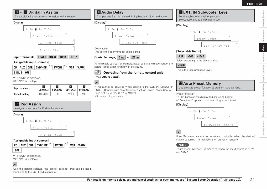
For details on how to select, set and cancel settings for each menu, see “System Setup Operation” (vpage 20).
d ~ hDigital In AssignSelect digital input connector to assign to this source.
[Input terminals] COAX1 COAX2 OPT1 OPT2 [Assignable input sources]
CD AUX CDR DVD/HDPz1
TV/CBLz2
VCR V.AUX
SIRIUS OFF
z1 : “DVD” is displayed.z2 : “TV” is displayed.
[Display]
1.Sp 2.In 3.Op
W
Input Setup
W
3 COAX1 :DVD
W
5 OPT1 :TV
Input terminalsd
COAXIAL1f
COAXIAL2g
OPTICAL1h
OPTICAL2
Default setting DVD/HDP CD TV/CBL VCR
[Assignable input sources]
CD AUX CDR DVD/HDPz1
TV/CBLz2
VCR V.AUX
OFF
z1 : “DVD” is displayed.z2 : “TV” is displayed.
With the default settings, the control dock for iPod can be used connected to the VCR (iPod) connector.
[Display]
1.Sp 2.In 3.Op
W
Input Setup
W
7 iPod :VCR
jiPod AssignAssign control dock for iPod to this source.
kAudio DelayCompensate for mismatched timing between video and audio.
Delay audio.This sets the delay time for audio signals.
[Variable range] 0 ms ~ 200 ms
With a movie source, for example, adjust so that the movement of the actors’ lips is synchronized with the sound.
Operating from the remote control unitPress [AUDIO DELAY].
[Display]
1.Sp 2.In 3.Op
W
Input Setup
W
8A.Delay: 0ms
• This cannot be adjusted when playing in the EXT. IN, DIRECT or STEREO mode (with “Front Speaker” set to “Large”, “Tone Control” to “OFF” and “MultEQ” to “OFF”).
• Store each input source.
A0Auto Preset MemoryUse the auto preset function to program radio stations.
If an FM station cannot be preset automatically, select the desired station by tuning it in manually, then preset it manually.
Press o to start.• “CH” blinks on the display and searching begins.• “Completed” appears once searching is completed.
lEXT. IN Subwoofer LevelSet the subwoofer level for playback.Select according to the player in use.
[Selectable items]
0dB +5dB +10dB :
Select according to the player in use.
+15dB :
This is the recommended level.
[Display]
1.Sp 2.In 3.Op
W
Input Setup
W
9EXT.In SW:+15
[Display]
1.Sp 2.In 3.Op
W
Input Setup
W
10 Preset <Start
NOTE“Auto Preset Memory” is displayed when the input source is “FM” and “AM”.
��
Gettin
g S
tartedC
on
nectio
ns
Setu
pP
layback
Rem
ote C
on
trol
Info
rmatio
nT
rou
blesh
oo
ting
ENGLISHS
pecifi
cation
s

For details on how to select, set and cancel settings for each menu, see “System Setup Operation” (vpage 20).
qPress o.w Using uiop, input the password (4 digits number) and press
ENTER.eSet the lock by pressing o p.
A2Edit Lock CodeChange the password (See “Parental Lock”).
qPress o.wInput old password (4 digits) using uiop, and press ENTER.eInput new password (4 digits) using uiop, and press ENTER. Be sure to memorize the password you have entered.rInput new password (4 digits) again using uiop, and press
ENTER. If the correct password is input, “Complete” is displayed, and the new password is modified.
A1Parental LockFor any channel, set the radio reception limits.
• The default password is “0000”. If you wish to change this password, set the new password with “Edit Lock Code”.
• If the password is incorrectly input, “Incorrect Code” is displayed, and proceed again from step q.
• If the password input is 3 digits or less, “Enter 4-digit” is displayed, and input again with a 4 digit password.
• While listening to the channel being played, you can also set parental lock (vpage 38).
NOTE“Parental Lock” is displayed when input source is “SIRIUS” , and connected to SIRIUS Tuner.
[Display]
1.Sp 2.In 3.Op
W
Input Setup
W
11ParentalLock<q
W
Code:[0000]w
W
SR001 :<Unlock>e
W
SR001 :< Lock >
[Selectable items]
Unlock : Do not lock selected channel(s).
Lock : Lock selected channel(s).
bWhen a Parental Locked channel is tuned, “Code : [ ]” is displayed, then input the password.
• If the old password is incorrectly input, “Incorrect Code” is displayed, and proceed again from step q.
• If the password input is 3 digits or less, “Enter 4-digit” is displayed, and input again with a 4 digit password.
• If the new password is not correctly input, “Disagreement” is displayed and the password does not change.
NOTE“Edit Lock Code” is displayed when the input source is “SIRIUS”.
[Display]
1.Sp 2.In 3.Op
W
Input Setup
W
12EditLockCode<q
W
Current:[0000]w
W
New:[0123]e
W
Repeat:[0123]r
W
Complete
��
Gettin
g S
tartedC
on
nectio
ns
Setu
pP
layback
Rem
ote C
on
trol
Info
rmatio
nT
rou
blesh
oo
ting
ENGLISH
Sp
ecificatio
ns

For details on how to select, set and cancel settings for each menu, see “System Setup Operation” (vpage 20).
a ~ dVolume ControlSet the main zone volume setting.
dMute Level
This sets the amount of attenuation of the volume when the mute mode is set in the main zone.
[Selectable items]
Full : The sound is cut off entirely.
–40dB : The sound is attenuated by 40 dB.
–20dB : The sound is attenuated by 20 dB.
aVolume Limit
Make a setting for maximum volume.
[Selectable items]
OFF : Do not set a maximum volume.
–20dB : Set the maximum volume to –20 dB.
–10dB : Set the maximum volume to –10 dB.
0dB : Set the maximum volume to 0 dB.
sPower On Level
This sets the volume set when the main zone’s power is turned on.
[Selectable items]
Last : Use the memorized setting from the last session.
– – – : Always use the muting on condition when power is turned on.
[Variable range]
–80dB ~ +18dB : Set the volume level when the power is turned on in units of 1 dB.
b The variable level when upper limit has been set with “Volume Limit” is “–80 dB ~ the set volume level”.
3. Option SetupMake various other settings.
a ~ d Volume Controlf Auto Surround Modeg Direct Mode Setuph Remote ID Setup
[Display]
1.Sp 2.In 3.Op
E
Option Setup
E
1 Limit :OFF
E
2 P.On :Last
E
3 Mute :Full
fAuto Surround ModeMake setting for memorizing surround mode setting for each input signal type.
[Selectable items]
ON : Memorize settings. Most recently stored surround mode is automatically selected.
OFF : Do not memorize settings. Surround mode does not change according to input signal.
The auto surround mode function lets you store in the memory the surround mode last used for playing the three types of input signals listed below.qAnalog and PCM 2-channel signals (STEREO)w2-channel signals of Dolby Digital, DTS or other multi-channel
format (DOLBY PLg Cinema)eMulti-channel signals of Dolby Digital, DTS or other multichannel
format (DOLBY/DTS SURROUND)b Default settings are indicated in ( ).
[Display]
1.Sp 2.In 3.Op
E
Option Setup
E
4AutoSurr.:ON
[Selectable items]
ON : Use MultEQ.
OFF : Do not use MultEQ.
gDirect Mode SetupSelect MultEQ use for DIRECT mode playback.
hRemote ID SetupSet remote control ID.
[Selectable items] 1 2 3 4
NOTEWhen using the AVR-589 with only the included remote control unit (RC-1104), there is no need to make settings.When using a separately sold remote control unit (RC-7000CI, etc.), this function can be used. Match the ID setting of the remote control unit and the receiver.
[Display]
1.Sp 2.In 3.Op
E
Option Setup
E
5 Direct :OFF
[Display]
1.Sp 2.In 3.Op
E
Option Setup
E
6 Remote ID:1
��
Gettin
g S
tartedC
on
nectio
ns
Setu
pP
layback
Rem
ote C
on
trol
Info
rmatio
nT
rou
blesh
oo
ting
ENGLISHS
pecifi
cation
s

��
Gettin
g S
tartedC
on
nectio
ns
Playb
ackR
emo
te Co
ntro
lIn
form
ation
Tro
ub
lesho
otin
g
ENGLISH
Sp
ecificatio
ns
Surround Modes
qStandard PlaybackThis is the mode for enjoying surround sound according to the program source.
Surround Playback of 2-channel Sources
Selecting the surround mode
Select by turning <SELECT/ENTER> or pressing [STD].
[Selectable items]
DOLBY PLg : The signals are decoded in DOLBY PLg for playback.
DTS NEO:6 : The signals are decoded in DTS NEO:6 for playback.
Select the mode to suit the source
Press <SURR. PARA> or [PARA]. Display “Mode” and select your desired mode using o p.
n DOLBY PLg
Cinema : This mode is suited for movie sources.
Music : This mode is suited for music sources.
Game : This mode is suited for games.
PL : This is the Pro Logic playback mode.
When this mode is selected, “DOLBY PL” is diplayed.
n DTS NEO:6
Cinema : This mode is suited for movie sources.
Music : This mode is suited for music sources.
Select the “Cinema”, “Music”, “Game” and “PL” modes at “Surround Parameter” – “Mode” (vpage 30).
Input signal DisplayDolby Digital Source
DOLBY DIGITAL (other than 2ch)
DOLBY DIGITAL
DTS Surround Source
DTS (5.1ch) /DTS 96/24
DTS SURROUND
DTS 96/24 (z)
z : This is displayed when the input signal is “DTS 96/24”.
• For details, see page 49.• To select these surround modes using <SELECT/ENTER> or press
[STD].
Playing Multi-channel Sources (Dolby Digital, DTS, etc.)
In the case of standard playback of multi channel sources, the AVR-589 recognizes the format of the multi-channel audio input signal and automatically operates the appropriate decoder for surround sound.
[Selectable items]
STANDARD :
Any of the surround modes in the “Display” column in the following table.The mode changes depending upon factors such as the• Input signalis being used.
op
<SELECT/ENTER>, op
<SURR. PARA>
op
[D/ST][STD][SIMU][PARA]
[Front]
[Rear]
Button located on both the main unit and the remote control unit BUTTONButton only on the main unit <BUTTON>Button only on the remote control unit [BUTTON]
Symbols used to indicate buttons in this manual
Setu
p

��
Gettin
g S
tartedC
on
nectio
ns
Playb
ackR
emo
te Co
ntro
lIn
form
ation
Tro
ub
lesho
otin
gENGLISH
Sp
ecificatio
ns
Input signal Display
Analog signal /PCM (2ch) /
Dolby Digital source /DTS source /
Other 2-channel digital signals
DIRECT
For details, see page 49.
eDirect Playback
rStereo Playback
Selecting the mode
Select by turning <SELECT/ENTER> or pressing [D/ST].
[Selectable items]
STEREO :
This is the mode for playing in stereo. The tone can be adjusted.Sound is output from the front left and right speakers and subwoofer.
Selecting the mode
Select by turning <SELECT/ENTER> or pressing [D/ST].
[Selectable items]
DIRECT :
In this mode the signals bypass the tone adjustment circuitry for high quality sound.The sound is output to the same channels as the input signal.
Depending on the program source being played, it may not be possible to achieve a satisfactory surround effect. In this case, try other modes to achieve a sound field suited to your tastes.
wDSP Simulation PlaybackThe desired mode according to the program source and viewing situation can be selected from among 7 DENON original surround modes.The surround parameters can be adjusted (vpage 47, 48) to achieve an even more realistic, powerful sound field.
Selecting the surround mode
Select by turning <SELECT/ENTER> or pressing [SIMU].
[Selectable items]
5CH STEREO : This mode is for enjoying stereo sound from all speakers.
ROCK ARENA : This mode is for enjoying the atmosphere of a live concert in an arena.
JAZZ CLUB : This mode is for enjoying the atmosphere of a live concert in a jazz club.
MONO MOVIE z : This mode is for playing monaural movie sources with surround sound.
VIDEO GAME : This mode is suited for achieving surround sound with video games.
MATRIX : This mode lets you add a sense of expansion to stereo music sources.
VIRTUAL : This mode is for enjoying surround effects using only the front speakers or headphones.
z: When playing sources recorded in monaural in the MONO MOVIE mode, the sound will be off balance with a single channel (left or right), so input to both channels.
Setu
p

��
Gettin
g S
tartedC
on
nectio
ns
Playb
ackR
emo
te Co
ntro
lIn
form
ation
Tro
ub
lesho
otin
g
ENGLISH
Sp
ecificatio
ns
1Press <SURR. PARA> or [PARA].Parameter is displayed.
2Use ui to select which parameters to adjust.Only those parameters which can be adjusted under the current playback status are displayed.
3Use o p to adjust the parameters.Repeat steps 2 and 3 to set each parameter.
Adjusting the Parameters
n To exit adjustment • Press <SURR. PARA> or [PARA] during adjustment. • If no adjustment is made for a period of about 5 seconds, the
adjustments made up that point are registered and the AVR-589 returns to the original mode.
Surround ParameterAdjust surround sound parameters.
The parameters (items) which can be adjusted differ depending upon the following conditions.
• Whether an input signal is present (when playing) or not (when stopped, etc.).
• The type of input signal • The type of surround mode
For details of which parameters can be adjusted in each surround mode, see “Surround Modes and Parameters” (vpage 47, 48).
a Modes Cinema EQd D. Comp (Dynamic Range Compression)f LFEg Center Imageh Panoramaj Dimensionk Center Widthl Delay TimeA0 Effect LevelA1 Room SizeA2 SW ATT (Subwoofer Attenuation)A3 SubwooferA4 Tone ControlA5 BassA6 TrebleA7 MultEQA8 Dynamic EQA9 Dynamic VolumeS0 DV Setting (Dynamic Volume Setting)S1 RESTORERS2 Night ModeS3 Default
Parameter
uiopMULTEQRESTORER
[NIGHT]
[DYNAMICVOLUME]
op
ui<SURR. PARA>
<DYN VOL.>
MULTEQ
RESTORER
uiop
[CINEMA][MUSIC]
[PARA]
[Front]
[Rear]
Button located on both the main unit and the remote control unit BUTTONButton only on the main unit <BUTTON>Button only on the remote control unit [BUTTON]
Symbols used to indicate buttons in this manual
Setu
p
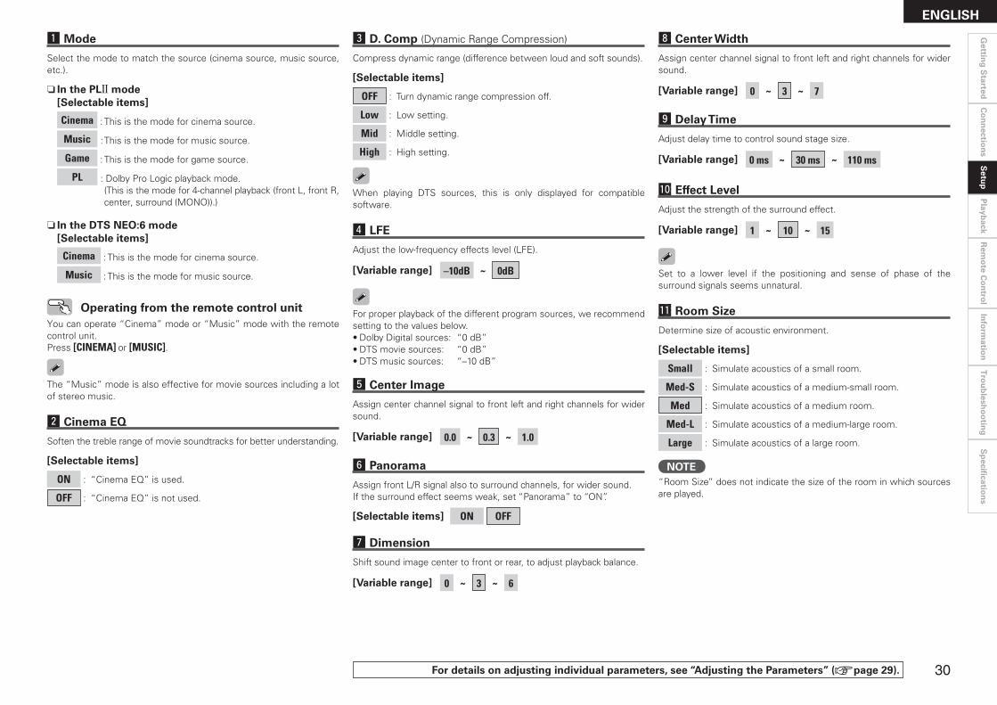
�0
Gettin
g S
tartedC
on
nectio
ns
Playb
ackR
emo
te Co
ntro
lIn
form
ation
Tro
ub
lesho
otin
gENGLISH
Sp
ecificatio
ns
A0Effect Level
Adjust the strength of the surround effect.
[Variable range] 1 ~ 10 ~ 15
Set to a lower level if the positioning and sense of phase of the surround signals seems unnatural.
A1Room Size
Determine size of acoustic environment.
[Selectable items]
Small : Simulate acoustics of a small room.
Med-S : Simulate acoustics of a medium-small room.
Med : Simulate acoustics of a medium room.
Med-L : Simulate acoustics of a medium-large room.
Large : Simulate acoustics of a large room.
NOTE“Room Size” does not indicate the size of the room in which sources are played.
hPanorama
Assign front L/R signal also to surround channels, for wider sound.If the surround effect seems weak, set “Panorama” to “ON”.
[Selectable items] ON OFF
jDimension
Shift sound image center to front or rear, to adjust playback balance.
[Variable range] 0 ~ 3 ~ 6
lDelay Time
Adjust delay time to control sound stage size.
[Variable range] 0 ms ~ 30 ms ~ 110 ms
kCenter Width
Assign center channel signal to front left and right channels for wider sound.
[Variable range] 0 ~ 3 ~ 7
fLFE
Adjust the low-frequency effects level (LFE).
[Variable range] –10dB ~ 0dB
gCenter Image
Assign center channel signal to front left and right channels for wider sound.
[Variable range] 0.0 ~ 0.3 ~ 1.0
For proper playback of the different program sources, we recommend setting to the values below.• Dolby Digital sources: “0 dB”• DTS movie sources: “0 dB”• DTS music sources: “–10 dB”
dD. Comp (Dynamic Range Compression)
Compress dynamic range (difference between loud and soft sounds).
[Selectable items]
OFF : Turn dynamic range compression off.
Low : Low setting.
Mid : Middle setting.
High : High setting.
When playing DTS sources, this is only displayed for compatible software.
For details on adjusting individual parameters, see “Adjusting the Parameters” (vpage 29).
sCinema EQ
Soften the treble range of movie soundtracks for better understanding.
[Selectable items]
ON : “Cinema EQ” is used.
OFF : “Cinema EQ” is not used.
The “Music” mode is also effective for movie sources including a lot of stereo music.
aMode
Select the mode to match the source (cinema source, music source, etc.).
n In the PLg mode[Selectable items]
Cinema : This is the mode for cinema source.
Music : This is the mode for music source.
Game : This is the mode for game source.
PL : Dolby Pro Logic playback mode. (This is the mode for 4-channel playback (front L, front R,
center, surround (MONO)).)
n In the DTS NEO:6 mode[Selectable items]
Cinema : This is the mode for cinema source.
Music : This is the mode for music source.
Operating from the remote control unitYou can operate “Cinema” mode or “Music” mode with the remote control unit.Press [CINEMA] or [MUSIC].
Setu
p

��
Gettin
g S
tartedC
on
nectio
ns
Playb
ackR
emo
te Co
ntro
lIn
form
ation
Tro
ub
lesho
otin
g
ENGLISH
Sp
ecificatio
ns n Operating conditions for each function
• Dynamic EQ : When “MultEQ” is set to “ON” • Dynamic Volume : When “Dynamic EQ” is set to “ON” • DV setting : When “Dynamic Volume” is set to “ON”
A7MultEQ
A8Dynamic EQ
A9Dynamic Volume
S0DV Setting
A4Tone Control
Turn tone adjustments on and off.
[Selectable items]
ON : Allow tone adjustment (treble, bass).
OFF : Playback without tone adjustment.
The tone cannot be adjusted when in the DIRECT mode.
A5Bass
Adjust low frequency range (bass).
[Variable range] –6dB ~ 0dB ~ +6dB
A6Treble
Adjust high frequency range (treble).
[Variable range] –6dB ~ 0dB ~ +6 dB
“Bass” and “Treble” can be set when “Tone Control” is set to “ON”.
A2SW ATT (Subwoofer Attenuation)
Attenuate subwoofer level when using EXT. IN mode.
[Selectable items]
ON : The input from the subwoofer channel is attenuated.
OFF : The input from the subwoofer channel is not attenuated. Usually use in this mode.
Set this to “ON” if the subwoofer channel level seems too high when playing audio signal.
A3Subwoofer
Turn subwoofer output on and off.
[Selectable items]
ON : The subwoofer is used.
OFF : The subwoofer is not used.
For details on adjusting individual parameters, see “Adjusting the Parameters” (vpage 29).
• If the settings of speakers for which “None” has been determined at “Auto Setup” are changed, “Audyssey”, “Audyssey Byp. L/R” and “Audyssey Flat” cannot be selected. Either perform Auto Setup again, or return to the setting after running Auto Setup with “System Setup” – “Speaker Setup” – “Restore”.
• When using headphones, “MultEQ” is set to “OFF”.
A7MultEQ
Select the type of room correction desired from the following list:
[Selectable items]
Audyssey : Optimize frequency response of all speakers.
Byp. L/R : Optimize frequency response of speakers except front L and R speakers.
Flat : Optimize frequency response of all speakers to flat response.
OFF : Turn equalizer off.
NOTE• “MultEQ” can only be set when Auto Setup has been performed.• “MultEQ” cannot be set in the following situations. • If “Auto Setup” fails to be completed. • After running Auto Setup, when the number of used speakers has
increased from the number of measured speakers.
Operating from the main unit or remote control unit
Press MULTEQ.
• When “Audyssey”, “Audyssey Byp. L/R” or “Audyssey Flat” is selected, the Audyssey MultEQ indicator lights green.
• After running Auto Setup, if the Speaker Configuration, Distance, Channel Level and Crossover Frequency have changed without increasing the number of speakers measured, the Audyssey MultEQ indicator lights red.
OFF
Audyssey Audyssey Byp. L/R
Audyssey Flat
NOTEWhen the “Dynamic EQ” setting is “ON”, setting is not possible.
Setu
p
A8Dynamic EQ
Audyssey Dynamic EQ solves the problem of deteriorating sound quality as volume is decreased by taking into account human perception and room acoustics. Audyssey Dynamic EQ works in tandem with Audyssey MultEQ to provide well-balanced sound for every listener at any volume level.
NOTE• “Dynamic EQ” can only be set when auto setup has been
performed.• “Dynamic EQ” cannot be set in the following situations. • If “Auto Setup” fails to be completed. • After running Auto Setup, when the number of used speakers has
increased from the number of measured speakers.• When “MultEQ” is set to “OFF”, “Dynamic EQ” is automatically set
to “OFF”.• “Night Mode” and “Tone Control” cannot be used jointly.
[Selectable items]
ON : Use Dynamic EQ function.
OFF : Do not use Dynamic EQ function.
Operating from the unit or remote control unit
Press <DYN VOL> or [DYNAMIC VOLUME].
Dynamic EQ / Volume : ON Dynamic EQ : ON / Volume : OFF
Dynamic EQ / Volume : OFF
Before running Auto Setup and after running Auto Setup, if the number of speakers has increased or you pressed <DYN VOL> or [DYNAMIC VOLUME], “Run Audyssey” is displayed. In this case, either perform Auto Setup again, or return to the setting after running Auto Setup with “System Setup” – “Speaker Setup” – “Restore”.

��
Gettin
g S
tartedC
on
nectio
ns
Playb
ackR
emo
te Co
ntro
lIn
form
ation
Tro
ub
lesho
otin
gENGLISH
Sp
ecificatio
ns
For details on adjusting individual parameters, see “Adjusting the Parameters” (vpage 29).
S0DV Setting (Dynamic Volume Setting)
Set Dynamic Volume effect.
[Selectable items]
Midnight : High setting affects volume the most, causing all sounds to be of equal loudness.
Evening : Middle setting prevents loud and soft sounds from being much louder and softer respectively than average sounds.
Day : Low setting provides the least adjustments to the loudest and softest of sounds.
A9Dynamic Volume
Audyssey Dynamic Volume solves the problem of large variations in volume level between television programs, commercials, and between the soft and loud passages of movies.Audyssey Dynamic EQ is integrated into Dynamic Volume so that as the playback volume is adjusted automatically, the perceived bass response, tonal balance, surround impression, and dialog clarity remain the same.
NOTE• “DV Setting” can only be set when auto setup has been performed.• “DV Setting” cannot be set in the following situations. • If “Auto Setup” fails to be completed. • After running Auto Setup, when the number of used speakers has
increased from the number of measured speakers. • If “Dynamic Volume” setting is “OFF”.
About Dynamic VolumeAudyssey Dynamic Volume™ solves the problem of large variations in volume level between television programs, commercials, and between the soft and loud passages of movies.Dynamic Volume looks at the preferred volume setting by the user and then monitors how the volume of program material is being perceived by listeners in real time to decide whether an adjustment is needed. Whenever necessary, Dynamic Volume makes the necessary rapid or gradual adjustments to maintain the desired playback volume level while optimizing the dynamic range. Audyssey Dynamic EQ is integrated into Dynamic Volume so that as the playback volume is adjusted automatically, the perceived bass response, tonal balance, surround impression, and dialog clarity remain the same whether watching movies, flipping between television channels, or changing from stereo to surround sound content.
About Dynamic EQAudyssey Dynamic EQ™ solves the problem of deteriorating sound quality as volume is decreased by taking into account human perception and room acoustics. Dynamic EQ selects the correct frequency response and surround levels moment-by-moment at any user-selected volume setting. The result is bass response, tonal balance, and surround impression that remain constant despite changes in volume. Dynamic EQ combines information from incoming source levels with actual output sound levels in the room, a prerequisite for delivering a loudness correction solution. Audyssey Dynamic EQ works in tandem with Audyssey MultEQ to provide well-balanced sound for every listener at any volume level.
NOTE• “Dynamic Volume” can only be set when auto setup has been
performed.• “Dynamic Volume” cannot be set in the following situations. • If “Auto Setup” fails to be completed. • After running Auto Setup, when the number of used speakers has
increased from the number of measured speakers.• When “MultEQ” is set to “OFF”, “Dynamic Volume” is automatically
set to “OFF”.• “Night Mode” and “Tone Control” cannot be used jointly.
[Selectable items]
ON : Use Dynamic Volume. The Dynamic Volume effect will be at the level of the “DV
Setting”.
OFF : Do not use Dynamic Volume.
Before running Auto Setup and after running Auto Setup, if the number of speakers has increased or you pressed <DYN VOL> or [DYNAMIC VOLUME], “Run Audyssey” is displayed. In this case, either perform Auto Setup again, or return to the setting after running Auto Setup with “System Setup” – “Speaker Setup” – “Restore”.
Operating from the unit or remote control unit
Press <DYN VOL> or [DYNAMIC VOLUME].
Setu
p
The default setting for “iPod” is “Mode3”. All others are set to “OFF”.
OFF Mode 1(RESTORER 64)
Mode 2(RESTORER 96)
Mode 3(RESTORER HQ)
S1RESTORER
This function restores compressed audio signals to how they were before compression and corrects the sense of volume of the bass and treble to obtain richer playback sound.
[Selectable items]
OFF :
Do not use RESTORER.
Mode1 (RESTORER 64):
Optimized mode for compressed sources with very weak highs.
Mode2 (RESTORER 96):
Apply suitable bass and treble boost for all compressed sources.
Mode3 (RESTORER HQ):
Optimized mode for compressed sources with normal highs.
About the RESTORER function• Such compressed audio formats as MP3, WMA (Windows Media
Audio) and MPEG-4 AAC reduce the amount of data by eliminating signal components that are hard for the human ear to hear. The RESTORER function generates the signals eliminated upon compression, restoring the sound to conditions near those of the original sound before compression. It also corrects the sense of volume of the bass to obtain richer sound with compressed audio signals.
• This is displayed on the “Surround Parameter” and can be set when the input source is selected to “SIRIUS” or analog signals (including FM/AM signals) or PCM signals (fs = 44.1/48 kHz) are input.
Operating from the main unit or remote control unit
Press RESTORER.
Dynamic EQ / Volume : ON
“Green” “Red”
Dynamic EQ : ON / Volume : OFF
Dynamic EQ / Volume : OFF
“Off”
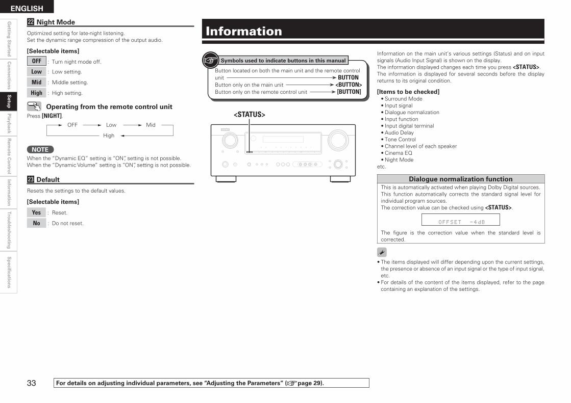
��
Gettin
g S
tartedC
on
nectio
ns
Playb
ackR
emo
te Co
ntro
lIn
form
ation
Tro
ub
lesho
otin
g
ENGLISH
Sp
ecificatio
ns
Operating from the remote control unitPress [NIGHT].
OFF Low Mid
High
S3Default
Resets the settings to the default values.
[Selectable items]
Yes : Reset.
No : Do not reset.
S2Night Mode
Optimized setting for late-night listening.Set the dynamic range compression of the output audio.
[Selectable items]
OFF : Turn night mode off.
Low : Low setting.
Mid : Middle setting.
High : High setting.
NOTEWhen the “Dynamic EQ” setting is “ON”, setting is not possible.When the “Dynamic Volume” setting is “ON”, setting is not possible.
For details on adjusting individual parameters, see “Adjusting the Parameters” (vpage 29).
Setu
p
Information
Dialogue normalization functionThis is automatically activated when playing Dolby Digital sources.This function automatically corrects the standard signal level for individual program sources.The correction value can be checked using <STATUS>.
OFFSET -4dB
The figure is the correction value when the standard level is corrected.
• The items displayed will differ depending upon the current settings, the presence or absence of an input signal or the type of input signal, etc.
• For details of the content of the items displayed, refer to the page containing an explanation of the settings.
Information on the main unit’s various settings (Status) and on input signals (Audio Input Signal) is shown on the display.The information displayed changes each time you press <STATUS>.The information is displayed for several seconds before the display returns to its original condition.
[Items to be checked] • Surround Mode • Input signal • Dialogue normalization • Input function • Input digital terminal • Audio Delay • Tone Control • Channel level of each speaker • Cinema EQ • Night Modeetc.
<STATUS>
Button located on both the main unit and the remote control unit BUTTONButton only on the main unit <BUTTON>Button only on the remote control unit [BUTTON]
Symbols used to indicate buttons in this manual

Preparations
1Press <POWER>.The power indicator lights red and the power is set to the standby mode.
2Press <ON/STANDBY> or [ON/SOURCE]. The power indicator flashes green and the power turns on.
b Also press [SOURCE SELECT] when in standby mode, the power turns on. In this case the input source is selected by remote control unit.
b Also press [QUICK SELECT] when in standby mode, the power turns on. In this case Quick Select is selected by remote control unit (vpage 41).
Turning the Power On
Turning the Power Off
q Press <ON/STANDBY> or [OFF].The power is set to the standby mode.
w Press <POWER>.The power indicator turns off, and so does the power.
NOTE Power continues to be supplied to some of the circuitry even when the power is in the standby mode. When leaving home for long periods of time or when traveling, either press <POWER> to turn off the power, or unplug the power cord from the power outlet.
Selecting the Input Source
Select the source using SOURCE SELECT.Turn <SOURCE SELECT> or press [SOURCE SELECT] to switch between input sources.
If “Rec Select” is selected for the input source, press <SOURCE> before turning <SOURCE SELECT>.
Setting the Input ModeSet the input mode for this source.
• When a digital signal is properly input, the “ ” indicator lights on the display. If the “ ” indicator does not light, check the digital input connector assignment and the connections.
• The surround mode cannot be set if the input mode is set to “EXT. IN”.
• Only set “PCM” and “DTS” when playing the respective signals.
[Selectable items]
Auto : Detect type of digital input signal and decode and play automatically.
PCM : Decode and play only PCM input signals.
DTS : Decode and play only DTS input signals.
Analog : Play only signals from analog input.
EXT. IN : Play only signals from EXT. IN input.
Press <INPUT MODE> or [INPUT].Each time you press the button, the input mode display will change.
Auto PCM DTS
AnalogEXT. IN
<ON/STANDBY><POWER><INPUT MODE>
<SOURCE>SOURCE SELECT
[OFF]
SOURCE SELECT[QUICK SELECT]
[ON/SOURCE]
SOURCESELECT
[INPUT]
[Front] [Rear]
Button located on both the main unit and the remote control unit BUTTONButton only on the main unit <BUTTON>Button only on the remote control unit [BUTTON]
Symbols used to indicate buttons in this manual
Playback
��
Gettin
g S
tartedC
on
nectio
ns
Setu
pP
layback
Rem
ote C
on
trol
Info
rmatio
nT
rou
blesh
oo
ting
ENGLISHS
pecifi
cation
s

Plug the headphones into the PHONES jack on the main unit.The sound from the speakers and pre-out connectors is automatically cut.
NOTEBe careful not to set the volume too high when using headphones.
Listening with Headphones
Press <SPEAKERS>.
Switching the front speakers
Video Select Function
Switch video input source while listening to audio signal.
Press <VIDEO SELECT> or [V.SEL] until the desired picture appears.
b To cancel, press <VIDEO SELECT> to select “SOURCE”.
Playing Video and Audio Equipment
1Prepare the equipment.
q Load the DVD, CD or other software in the player. (vSee the operating instructions of the respective devices.)w To play a video device, switch the monitor input. (vSee the monitor’s operating instructions.)
2Use SOURCE SELECT to select the input source.
3Start playback. (vSee the operating instructions of the respective devices.)
Basic Operation
Press [MUTING].
To cancel, press [MUTING] again. Muting can also be canceled by adjusting the master volume.
Turning Off the Sound Temporarily (Muting)
Press <STATUS>.The current program source and various settings are indicated on the display.For details, refer to “Information” (vpage 33).
Checking the currently playing program source, etc.
Switching the brightness of the display
Press <DIMMER>.
Bright Dim
DarkOFF
Either turn <MASTER VOLUME> or press [MASTER VOLUME].
[Variable range] – – – –80.0dB ~ +18.0dB
Operations During Playback
Adjusting the Master Volume
The remote control unit can be used to operate external devices.See “Remote Control Unit Operations” (vpage 42).
NOTEThe adjustable range will differ depending upon factors such as the type of input signal and the channel level setting.
When setting to “OFF”, the display brightness of the menu setting in operation changes to “Dark”.
��
Gettin
g S
tartedC
on
nectio
ns
Setu
pP
layback
Rem
ote C
on
trol
Info
rmatio
nT
rou
blesh
oo
ting
ENGLISH
Sp
ecificatio
ns
SHIFTSOURCE SELECT
TUNING<PRESET CHANNEL>
ENTER,op
ui
<MUSTER VOLUME>
<SPEAKERS><VIDEO SELECT>
<DIMMER>BAND<STATUS>
TUNINGSHIFT
[SOURCECONTROL 1]
[SOURCECONTROL 2]
[TUNER]
[CHANNEL + –]
[MASTERVOLUME]
[MUTING]
SOURCESELECT
TUNING
[MEMORY]
BAND
[V.SEL]
SOURCESELECT[TUNER]
[MODE]
[Front] [Rear]
Button located on both the main unit and the remote control unit BUTTONButton only on the main unit <BUTTON>Button only on the remote control unit [BUTTON]
Symbols used to indicate buttons in this manual
PHONES jack

Presetting Radio Stations(Preset Memory)Your favorite broadcast stations can be preset so that you can tune them in easily. Up to 56 stations can be preset.
1Tune in the broadcast station you want to preset.
2Press [MEMORY].
3Press SHIFT to select the block (A to G) in which the station is to be preset.
4Press <PRESET CHANNEL> or [CHANNEL + –] to select the preset number (1 to 8).
5Press [MEMORY] again to complete the setting.
• To preset other stations, repeat steps 1 to 5.• Stations can be preset automatically at “System Setup” – “Input
Setup” – “Auto Preset Memory” (vpage 24).
NOTEPreset stations are erased by overwriting them.
1Press SHIFT to select the memory block (A to G).
2Press <PRESET CHANNEL> or [CHANNEL + –] to select the desired preset channel (1 to 8).
n Default settingsAuto tuner presets
A1 ~ A8 87.5 / 89.1 / 98.1 / 107.9 / 90.1 / 90.1 / 90.1 / 90.1 MHz
B1 ~ B8 520 / 600 / 1000 / 1400 / 1500 / 1710 kHz, 90.1 / 90.1 MHz
C1 ~ C8 90.1 MHzD1 ~ D8 90.1 MHzE1 ~ E8 90.1 MHzF1 ~ F8 90.1 MHzG1 ~ G8 90.1 MHz
Listening to Preset Stations
1Either turn <SOURCE SELECT> or press [TUNER] to select “TUNER”.
2Set [SOURCE CONTROL 1] to “AUDIO” and [SOURCE CONTROL 2] to “TUNER”.
(vpage 42 “Remote Control Unit Operations”)
3Press BAND to select “FM” or “AM”.
4Tune in the desired broadcast station.
q To tune in automatically (Auto Tuning)Press [MODE] to light the “AUTO” indicator on the display, then use TUNING to select the station you want to hear.
w To tune in manually (Manual Tuning)Press [MODE] to turn off the display’s “AUTO” indicator, then use TUNING to select the station you want to hear.
Listening to FM/AM Broadcasts
• If the desired station cannot be tuned in with auto tuning, tune it in manually.
• When tuning in stations manually, press and hold TUNING to change frequencies continuously.
Basic Operation
��
Gettin
g S
tartedC
on
nectio
ns
Setu
pP
layback
Rem
ote C
on
trol
Info
rmatio
nT
rou
blesh
oo
ting
ENGLISHS
pecifi
cation
s

1Either turn <SOURCE SELECT> or press [SAT TU] to select “SIRIUS”.
2Set [SOURCE CONTROL 1] to “AUDIO” and [SOURCE CONTROL 2] to “TUNER”.
(vpage 42 “Remote Control Unit Operations”)
3Use TUNING to search the channel.When selecting channel, the Channel No. and Channel name are displayed.
• The channel switches continuously when TUNING is pressed and held.
• SIRIUS Radio channels can be preset using the same procedure as for FM/AM stations (vpage 36 “Presetting Radio Stations (Preset Memory)” and “Listening to Preset Stations”).
b You cannot perform “Auto Preset”.• The song title, artist name, composer name, category and reception
level can be checked by pressing <STATUS>.• When tuning a channel to which “Parental Lock” is applied, “Code:
[ ]” is displayed, so enter the password.
Basic Operation
Checking the SIRIUS Signal Strength and Radio ID
1Either turn <SOURCE SELECT> or press [SAT TU] to select “SIRIUS”.
2Press <STATUS> until “SIG.” appears on the display.The display will switch as shown below, depending on the reception conditions.
Display StatusEXCELLENT Signal strength is excellentGOOD Signal strength is goodWEAK Signal strength is weakNO SIGNAL No signal
3Adjust the position of the antenna until “SIG.: EXCELLENT” is shown on the display.
4Press <STATUS> until the channel you want to check (example: “SR001”) is displayed.
5Press TUNING and select channel 0 (SR000).Channel No. and SIRIUS ID are alternately shown on the display.
SR000 SIRIUS ID
b Write your own SIRIUS ID for storage use. SIRIUS ID :
What is SIRIUS Satellite Radio?
Simply The Best Radio on RadioTM with all your favorite entertainment including 100% commercial-free music, plus superior sports coverage, uncensored talk and comedy, world-class entertainment, news, weather and more for your car, home or office. For more information visit sirius.com or siriuscanada.ca
Sirius is available in the US for subscribers with addresses in the continental US and is available in Canada for subscribers with a Canadian address. Required subscription plus compatible SIRIUS tuner and antenna are required and sold separately. SIRIUS Programming is subject to change. Visit sirius.com for the most complete and up-to-date channel lineup and product information. “SIRIUS” and the SIRIUS dog logo and related marks are trademarks of Sirius Satellite Radio Inc. All rights reserved.
Listening to SIRIUS Satellite Radio Programs
NOTEYou can check Satellite and Terrestrial antenna signal strength each time you press <STATUS>. (On the display, “S” indicates Satellite, and “T” indicates Terrestrial.)
*************** SIRIUS ID
��
Gettin
g S
tartedC
on
nectio
ns
Setu
pP
layback
Rem
ote C
on
trol
Info
rmatio
nT
rou
blesh
oo
ting
ENGLISH
Sp
ecificatio
ns
<SOURCE SELECT>
<STATUS><ON/STANDBY> TUNING
ui
op
[iPod]
[OFF]
[SOURCECONTROL 1]
[SOURCECONTROL 2]
[ENTER]
TUNING
[uiop]
[SAT TU]
[ENTER]
[MODE]
[iPod]TUNING
[SAT TU]
[uiop]
[Front] [Rear]
Button located on both the main unit and the remote control unit BUTTONButton only on the main unit <BUTTON>Button only on the remote control unit [BUTTON]
Symbols used to indicate buttons in this manual

iPod® PlaybackThe music on an iPod can be played by using the control dock for iPod (ASD-1R, ASD-11R, ASD-3N or ASD-3W, sold separately).The operation can also be performed using the buttons on the remote control unit.
iPod is a trademark of Apple Inc., registered in the U.S. and other countries.
b The iPod may only be used to copy or play contents that are not copyrighted or contents for which copying or playback is legally permitted for your private use as an individual. Be sure to comply with applicable copyright legislation.
4Press [MODE] and hold it down for a 2 seconds or more to select the display mode.To switch between modes, press and hold down the button.When remote mode is active, “Remote” is displayed.
[Selectable mode] Browse mode Remote mode
Display location Main unit display iPod display
Playable files
Audio file S S
Video file Sz1 Sz2
Active buttons
Remote control unit (AVR-589)
S S
iPod A S
z1 : When using an ASD-3N or ASD-3W control dock for iPod.z2 : Video may not be output, depending on the combination of
ASD-1R or ASD-11R and iPod.
• With the default settings, the iPod can be used connected to the VCR (iPod) connector.
• Use the RESTORER mode to expand the low and high frequency components of compressed audio files and achieve a richer sound. The default setting is “Mode3” (vpage 32).
• Press <ON/STANDBY> or [OFF] and set the AVR-589’s power to the standby mode before disconnecting the iPod. Also switch the input source to one to which “iPod Assign” is not assigned before disconnecting the iPod.
• When using an ASD-3N or ASD-3W control dock for iPod, refer to the respective manual to operate.
1Make the necessary preparations.
qSet the iPod in the DENON control dock for iPod. (vSee the control dock for iPod’s operating instructions.)w Assign the control dock for iPod’s input. The input for the control dock for iPod is assigned to VCR by
default.
“System Setup” – “Input Setup” – “iPod Assign” (vpage 24)
2Either turn <SOURCE SELECT> or press [iPod] to select the input source assigned in step 1-w above.
3Set [SOURCE CONTROL 1] to “AUDIO” and [SOURCE CONTROL 2] to “iPod/NETWORK”.
(v page 42 “Remote Control Unit Operations”)
Preparations
Searching Categories
1Press [o p].
CATEGORY SEARCH
CAT: Pops
2Use [o p] to select the category, then use [ui] to select the desired channel.
Channel category
• “UPDATING” is displayed while the encording code is being updated.
• “SIRIUS UPDATING” is displayed when updating SIRIUS tuner firmware.
• Refer to “Troubleshooting” (vpage 52) regarding other messages.
Parental Lock
• Channels under Parental Lock cannot be tuned in by performing Tuning Up/Down or by category search.
• Channels stored in preset memory can be tuned in by the preset channel select operation, even if Parental Lock is applied.
• When a channel to which Parental Lock is applied is being played, Parental Lock for that channel is cancelled by performing Step 2.
• See “Edit Lock Cord” (vpage 25) for the method of changing Parental Lock Cord.
• You can also set “Parental Lock” from the system setup (vpage 25).
��
Gettin
g S
tartedC
on
nectio
ns
Setu
pP
layback
Rem
ote C
on
trol
Info
rmatio
nT
rou
blesh
oo
ting
ENGLISHS
pecifi
cation
s
1Tune to the channel you want to lock.
2Press [ENTER] for at least 3 seconds. “Code: [ ]” is displayed.
3Enter the 4-digit lock code using uiop. When you enter the correct code, the corresponding channel is locked.
4Press [ENTER].

• To check the name of the title, the artist or the album when playing in browse mode, press <STATUS>.
• The folder name and the file name can be displayed in browse mode.Only alphanumeric characters and certain symbols can be displayed. Any characters that cannot be displayed are replaced with “ . (period)”.
Viewing Still Pictures or Videos on the iPodPhoto and video data on the iPod can be viewed on the monitor. Only for iPod equipped with slideshow or video functions.
1Press and hold [MODE] to set the Remote mode.
2Watching the iPod’s screen, use [ui] to select “Photos” or “Videos”.
3Press [ENTER] until the image you want to view is displayed.
“TV Out” at the iPod’s “Slideshow Settings” or “Video Settings” must be set to “On” in order to display the iPod’s photo data or videos on the monitor. For details, see the iPod’s operating instructions.
Listening to Audio
1Use [ui] to select the item, then press [ENTER] or [p] to select the music file to be played.
2Press [ENTER] or [p].Playback starts.
n Stopping playback temporarilyDuring playback, press [ENTER] or [1].Press again to resume playback.
n Fast-forwarding or fast-reversingDuring playback, press and hold [6] (to fast-reverse) or [7] (to fast-forward).
n To cue to the beginning of a trackDuring playback, press [8] or [9].
n To stopDuring playback, either press and hold [ENTER] or press [2].
n Playing repeatedlyPress [TUNING –].
[Selectable items] All One OFF
n Shuffling playbackPress [TUNING +].
[Selectable items] Albums Songs OFF
NOTE• Depending on the type of iPod and the software version, some
functions may not operate.• DENON will accept no responsibility whatsoever for any loss of iPod
data.
1Press and hold [MODE] to set the Browse mode.
2Watching the display, use [ui] to select “iPod”, then press [p] or [ENTER].
3Use [ui] to select “Video”, then press [p] or [ENTER].
4Use [ui] to select the video file to be played, then press [p] or [ENTER].
When viewing a still picture, perform the same operation as with ASD-1R or ASD-11R.
When using an ASD-3N or ASD-3W
When using an ASD-1R or ASD-11R
��
Gettin
g S
tartedC
on
nectio
ns
Setu
pP
layback
Rem
ote C
on
trol
Info
rmatio
nT
rou
blesh
oo
ting
ENGLISH
Sp
ecificatio
ns
[Front] [Rear]
Button located on both the main unit and the remote control unit BUTTONButton only on the main unit <BUTTON>Button only on the remote control unit [BUTTON]
Symbols used to indicate buttons in this manual
<STATUS>
[ENTER][uiop]
[6], [7]
[1][2]
[8], [9][ENTER]
[MODE]
[TUNING + –]
[uiop]

Recording on an External Device(REC OUT mode)You can listen to one program source while recording a different program source.
1Press <REC SELECT> until “RECOUT” appears on the display.
2Turn <SOURCE SELECT> to choose the input source to be recorded.The “REC” indicator and the indicator for the selected source light.
RECOUT SOURCE RECOUT TUNER RECOUT SIRIUS····
3Play the program source. For operating instructions, refer to the respective equipment’s operating instructions.To record FM or AM broadcasts, select the broadcast (vpage 36).
4Start recording.For operating instructions, refer to the respective equipment’s operating instructions.
Other Operations• To cancel, press <REC SELECT>, then turn <SOURCE SELECT> until
“RECOUT SOURCE” is displayed.• Make a test recording before starting the actual recording.
NOTE• Recordings you make are for your personal enjoyment and should
not be used for other purposes without permission of the copyright holder.
• Digital signals are not output from the REC OUT (CDR/TAPE and VCR) connector.
• Audio and video signals input from the VCR IN connector are not output from the VCR OUT connector. Audio signal input from the CD-R/TAPE IN connector are not output from the CD-R/TAPE OUT connector.
Convenient Functions
1Press <SELECT/ENTER> or [CH SELECT/ENTER].
FL Vol.+ 1.5dB
2Use ui, <SELECT/ENTER> or [CH SELECT/ENTER] to select the speaker.The speaker that can be set switches each time one of the buttons is pressed.
3Use o p to adjust the volume.
b In the case of a subwoofer, reducing the volume when it is at “–12 dB” will change the setting to OFF (none).
Channel LevelYou can adjust the channel level either according to the playback sources or to suit your taste, as described below.
<SOURCE SELECT>
<SELECT/ENTER>,op
ui
<REC SELECT>
[CH SELECT/ ENTER]
uiop
uiop
[CH SELECT/ENTER]
[Front] [Rear]
Button located on both the main unit and the remote control unit BUTTONButton only on the main unit <BUTTON>Button only on the remote control unit [BUTTON]
Symbols used to indicate buttons in this manual
Other Operations and Functions
�0
Gettin
g S
tartedC
on
nectio
ns
Setu
pP
layback
Rem
ote C
on
trol
Info
rmatio
nT
rou
blesh
oo
ting
ENGLISHS
pecifi
cation
s

Quick Select FunctionWith this function, the currently playing input source, volume level, surround mode, MultEQ, Dynamic Volume, DV setting and front speaker can be stored in the memory.
1Set the input source, input mode, surround mode, MultEQ settings and volume to the conditions you want to store.
2Press and hold QUICK SELECT until “Memory” appears on the display.The current settings will be memorized.
To call out the settings, press QUICK SELECT at which the desired settings were stored.
Input Source VolumeQuick Select 1 DVD/HDP –40 dBQuick Select 2 TV/CBL –40 dBQuick Select 3 VCR –40 dB
[Quick Select Defaults]
Personal Memory Plus FunctionThis function sets the settings (input mode, surround mode, MultEQ, Dynamic EQ, Dynamic Volume, audio delay etc.) last selected for the individual input sources.When you switch to an input source, the settings are automatically set to the ones that were set the last time that input source was used.
The surround parameters, tone control, MultEQ settings and the volumes of the different speakers are stored for the individual surround modes.
Last Function MemoryThis stores the settings as they were directly before the standby mode was set.When the power is turned back on, the settings are restored to as they were directly before the standby mode was set.
Backup MemoryThe various settings are backed up for about 1 week, even if the power is turned off or the power cord is disconnected.
Resetting the MicroprocessorPerform this procedure if the display is abnormal or if operations cannot be performed.When the microprocessor is reset, all the settings are reset to their default values.
1Turn off the power using <POWER>.
2Press <POWER> while simultaneously pressing <INPUT MODE> and <SPEAKERS A>.
3Once the display starts flashing at intervals of about 1 second, release the two buttons.
If in step 3 the display does not flash at intervals of about 1 second, start over from step 1.
��
Gettin
g S
tartedC
on
nectio
ns
Setu
pP
layback
Rem
ote C
on
trol
Tro
ub
lesho
otin
g
ENGLISH
Sp
ecificatio
ns
Button located on both the main unit and the remote control unit BUTTONButton only on the main unit <BUTTON>Button only on the remote control unit [BUTTON]
Symbols used to indicate buttons in this manual
<INPUTMODE> QUICK SELECT
<POWER> <SPEAKERS A>
[QUICK SELECT]
[Front]Info
rmatio
n

Depending on the model and year of manufacture of your equipment, some buttons may not operate.
[SOURCECONTROL 1]
[SOURCECONTROL 2]
1Set [SOURCE CONTROL 1] to “AUDIO”.
2Set [SOURCE CONTROL 2] to the position for the component to be operated (CD, iPod/NETWORK or TUNER).
3Operate the audio component.
b For details, refer to the component’s operating instructions.b While this remote control unit is compatible with a wide range
of infrared controlled components, it may be the case that some component models cannot be operated with this remote control unit.
1Set [SOURCE CONTROL 1] to “AUDIO” or “VIDEO”.
b Set to the AUDIO side for the CD position, and to the VIDEO side for the DVD/HDP, VCR, SAT/CABLE or TV position.
2Set [SOURCE CONTROL 2] to the component to be registered.
3Press [DVD/HDP POWER] and [TV POWER] at the same time.
The indicator starts flashing.
4Press [NUMBER] and input the 3-digit number of the brand of the component to be preset. The numbers are shown in the Preset Code Table (vEnd of this manual).
5To store the codes of another component in the memory, repeat steps 1 to 4.
• The signals for the pressed buttons are emitted while setting the preset memory. To avoid accidental operation, cover the remote control unit’s transmitting window while setting the preset memory.
• Depending on the model and year of manufacture, this function cannot be used for some models, even if they are of makes listed in the list of preset codes.
• Some manufacturers use more than one type of remote control code. Refer to the included list of preset codes to change the number and verify correct operation.
• The preset memory can be set for one component only among the following: DVD/HDP and SAT/CABLE.
• VDP (Video Disc Player) can be preset when [SOURCE CONTROL 2] is set to “DVD/HDP”.
1Set [SOURCE CONTROL 1] to “AUDIO” or “VIDEO”.
b Set to the AUDIO side for the CD position, and to the VIDEO side for the DVD/HDP, VCR, SAT/CABLE or TV position.
2Set [SOURCE CONTROL 2] to the component you want to operate.
3Operate the component.
b For details, refer to the component’s operating instructions.b Some models cannot be operated with this remote control unit.
[DVD/HDP POWER]
[NUMBER]
[TV POWER]
[Front]
[Rear]
Remote Control Unit Operations
Operating DENON Audio Components
Operating Preset Components
Presetting• DENON and other makes of components can be operated by
setting the preset memory.• Operation is not possible for some models.
��
Gettin
g S
tartedC
on
nectio
ns
Setu
pP
layback
Rem
ote C
on
trol
Info
rmatio
nT
rou
blesh
oo
ting
ENGLISHS
pecifi
cation
s

[TUNING + – / TV VOL + –],
[MODE,TOP MENU],
[BAND, PICTURE ADJUST],
[MEMORY, SUBTITLE]
[SETUP],[uiop],[AUDIO],[ENTER],[DISPLAY], [RETURN]
[NUMBER](0~9, +10)
[OFF]
[SOURCE CONTROL 1]
[1], [2],[SHIFT, 3],
[0, SKIP + / FAVORITE],[TUNING, 6 7],
[8 9, CH + –]
[ON/SOURCE]
[SOURCECONTROL 2]
[SETUP],[uiop],[AUDIO], [ENTER],[DISPLAY], [RETURN],[MENU/GUIDE]
Functions of Buttons by Component
Device operated CD Player iPod Tuner DVD Player
Blu-ray Disc Player
Video Disc Player (VDP)
Video DeckSatellite Receiver
Cable TVTV
(Monitor)SOURCE
CONTROL 1 AUDIO VIDEO
SOURCE CONTROL 2 CD
iPod/NETWORK
TUNER DVD / HDP VCR SAT / CABLE TV
OFF – – – Power off Power off – – – – –
ON/SOURCE – – – Power on Power onPower on /
StandbyPower on /
StandbyPower on /
StandbyPower on /
StandbyPower on /
Standby
1 Play Play / Pause – Play Play Play Play
Punch through
Punch through
Punch through
2 Stop Stop – Stop Stop Stop Stop
SHIFT, 3 Pause – Shift Pause Pause Paus e Pause
0, SKIP + /
FAVORITEDisc skip +
b Favorites Direct
– Disc skip – – –
TUNING, 6 7
Manual search
(fast-reverse / fast-
forward)
Manual search
(fast-reverse / fast-
forward)
Tuning down / up
Manual search
(fast-reverse / fast-
forward)
Manual search
(fast-reverse / fast-
forward)
Manual search
(fast-reverse / fast-forward)
Manual search
(fast-reverse / fast-
forward)
8 9, CH + –
Auto search (cue)
Auto search (cue)
Tuner Channel – / +
Auto search (cue)
Auto search (cue)
Auto search (cue)
Switch channels
(–, +)
SETUP – – – Setup Setup – – – – –
uio p – Cursor –Cursor
operationCursor
operation– –
Cursor operation
Cursor operation
Cursor operation
AUDIO – – –Switching the audio
signal
Switching the audio
signal– – – – –
ENTER – Enter – Enter setting Enter setting – – Enter setting Enter setting Enter setting
DISPLAY – – –Switching the display
Switching the display
– –Switching the display
Switching the display
Switching the display
RETURN – – – Return Return – – Return Return Return
MENU / GUIDE
– – –Calling out the menus
Calling out the menus
– –Calling out the menus
Calling out the menus
Calling out the menus
n Front
b The iPod/NETWORK’s FAVORITE button can be operated when using a control dock for iPod ASD-3N/3W.
��
Gettin
g S
tartedC
on
nectio
ns
Setu
pP
layback
Rem
ote C
on
trol
Info
rmatio
nT
rou
blesh
oo
ting
ENGLISH
Sp
ecificatio
ns
n Fr nt
n Rear

Device operated
CD Player iPod Tuner DVD PlayerBlu-ray Disc
PlayerVideo Disc
Player (VDP)Video Deck
Satellite Receiver
Cable TVTV
(Monitor)SOURCE
CONTROL 1AUDIO VIDEO
SOURCE CONTROL 2
CDiPod/
NETWORKTUNER DVD / HDP VCR SAT / CABLE TV
POWER – – –Power on/off
Power on/off Power on/off Power on/off Power on/off Power on/off Power on/off
NUMBER (0 ~ 9, +10)
– – –Number
input / Track selection
Number input / Track selection
Number input / Track
selection– Channels Channels Channels
TUNING (+, –) /
TV VOL (+, –)
q CDRandomw CDRepeat
q iPodRandomw iPodRepeat
q Tuning upw Tuning
down
q DVDRandomw DVDRepeat
q Blu-ray DiscRandom
w Blu-ray DiscRepeat
q TVVolume dw TV
Volume f
q TVVolume dw TV
Volume f
q DBSVolume dw DBS
Volume f
q CableVolume dw CableVolume f
q TVVolume dw TV
Volume f
MODE, TOP MENU
–
Page search mode (once) and Browse/
Remote mode
switching (Press and
hold)
Switch search modes
Calling out the menus
Calling out the top menus
– –Calling out the menus
Calling out the menus
Calling out the menus
SETUP – – – Setup Setup – – – – –
uio p – – –Cursor
operationCursor
operation– –
Cursor operation
Cursor operation
Cursor operation
AUDIO – – – Audio Audio – – – – –BAND,
PICTURE ADJUST
– b1 Top menuAM / FM switching
Picture adjust
Picture adjust – – – – –
ENTER – – – Enter setting Enter setting – – Enter setting Enter setting Enter settingMEMORY, SUBTITLE
–b1 Favorite
memoryPreset
memory Subtitle Subtitle – – – – –
DISPLAY – – –Switching the display
Switching the display
– –Switching the display
Switching the display
Switching the display
RETURN – – – Return Return – – Return Return ReturnDefault setting
(Preset code)
DENON (111)
– –DENON
(111)b2 DENON
(121)–
HITACHI (108)
–ABC (007)
HITACHI (134)
Special Remarks
q – – q, w q q, e q, e
GSpecial RemarksHqOnly one device can be set in the preset memory for each mode.
When a new preset code is registered, the existing code is automatically erased.
wFor some brands, the DVD remote control buttons may have different function names. Check beforehand.
eOne of the following buttons can be assigned to the TV and satellite receiver or cable TV: CD, iPod/NETWORK, TUNER, DVD/HDP, VCR (vpage 44 “Punch Through Function”).
b1: This button can be operated when using a control dock for iPod ASD-3N/3W.
b2: The initial setting of Preset code is 111 (DVD Player). With the Blu-ray Disc Player setting, when you have set the
remote controller code to “DENON2”, use the Blu-ray Disc Player preset code “121”.
��
Gettin
g S
tartedC
on
nectio
ns
Setu
pP
layback
Rem
ote C
on
trol
Info
rmatio
nT
rou
blesh
oo
ting
ENGLISHS
pecifi
cation
s
1Set [SOURCE CONTROL 1] to “VIDEO”.
2Set [SOURCE CONTROL 2] to the component to be registered (SAT/CABLE or TV).
3Press [MEMORY] and [RETURN] at the same time.The indicator starts flashing.
4Input the number of the component you want to set.
No.
CD 1
iPod/NETWORK 2
TUNER 3
DVD/HDP 4
VCR 5
No setting 0
Punch Through Function“Punch Through” is a function allowing you to operate 1, 2, 3, 0, 6, 7, 8 and 9 on CD, iPod/NETWORK, TUNER, DVD/HDP or VCR components when in the SAT/CABLE or TV mode. By default, nothing is set.
n Rear

Examples of speaker layoutsBelow we introduce examples of speaker layouts. Refer to these to arrange your speakers according to their type and how you want to use them.
About Speaker Installation
Other Information
Basic setting
DTS 96/24 is a digital audio format enabling high sound quality playback in 5.1-channels with a sampling frequency of 96 kHz and 24 bit quantization on DVD-Video.
Subwoofer
Surround speakers
Monitor
Center speakerFront speakers
60°
120°
2 to 3 feetFront speaker
Surround speaker
GAs seen from aboveH GAs seen from the sideH
Dolby Digital
Dolby Digital is a multichannel digital signal format developed by Dolby Laboratories.A total of 5.1-channels are played: 3 front channels (“FL” , “FR” and “C”), 2 surround channels (“SL” and “SR”) and the “LFE” channel for low frequencies.Because of this, there is no crosstalk between channels and a realistic sound field with a “three-dimensional” feeling (sense of distance, movement and positioning) is achieved.A real, overpowering sense of presence is achieved when playing movie sources in AV rooms as well.
Surround
Dolby Surround
The AVR-589 is equipped with a digital signal processing circuit that lets you play program sources in the surround mode to achieve the same sense of presence as in a movie theater.
Dolby Pro Logic g
Dolby Pro Logic g is a matrix decoding technology developed by Dolby Laboratories.Regular music such as that on CDs is encoded into 5-channels to achieve an excellent surround effect.The surround channel signals are converted into stereo and full band signals (with a frequency response of 20 Hz to 20 kHz or greater) to create a “three-dimensional” sound image offering a rich sense of presence for all stereo sources.
Manufactured under license from Dolby Laboratories.“Dolby”, “Pro Logic” and the double-D symbol are trademarks of Dolby Laboratories.
DTS Surround
DTS Digital Surround
DTS Digital Surround is the standard digital surround format of DTS, Inc., compatible with a sampling frequency of 44.1 or 48 kHz and up to 5.1-channels of digital discrete surround sound.
DTS NEO:6™ Surround
DTS NEO:6™ is a matrix decoding technology for achieving 5.1-channel surround playback with 2-channel sources. It includes “DTS NEO:6 Cinema” suited for playing movies and “DTS NEO:6 Music” suited for playing music.
DTS 96/24
DTS 96/24 is a digital audio format enabling high sound quality playback in 5.1-channels with a sampling frequency of 96 kHz and 24 bit quantization on DVD-Video.
Manufactured under license under U.S. Patent #’s: 5,451,942; 5,956,674; 5,974,380; 5,978,762; 6,487,535; 7,003,467 & other U.S. and worldwide patents issued & pending. DTS, DTS Digital Surround, and Neo:6 are registered trademarks and the DTS logos, Symbol and DTS 96/24 are trademarks of DTS, Inc. ©1996-2007 DTS, Inc. All Rights Reserved.
��
Gettin
g S
tartedC
on
nectio
ns
Setu
pP
layback
Rem
ote C
on
trol
Mu
lti-Zo
ne
Info
rmatio
nT
rou
blesh
oo
ting
ENGLISH
Sp
ecificatio
ns

HDMI(High-Definition Multimedia Interface)
HDMI is a digital interface standard for next generation TVs based on DVI (Digital Visual Interface) standards and optimized for use in consumer equipment.Non-compressed digital video and multi-channel audio signals are transmitted with a single connection.HDMI is also compatible with HDCP (High-bandwidth Digital Contents Protection), a technology for protecting copyrights that encrypts digital video signals in the same was as with DVI.
“HDMI”, “HDMI logo” and “High-Definition Multimedia Interface” are trademarks or registered trademarks of HDMI Licensing LLC.
Deep Color
Eliminates on-screen color banding, for smooth tonal transitions and subtle gradations between colors.Enables increased contrast ratio.Can represent many times more shades of gray between black and white.At 30-bit pixel depth, a four times improvement would be the minimum, and the typical improvement would be eight times or more.
xvYCC
Next-generation “xvYCC” color space supports 1.8 times as many colors as existing HDTV signals.Lets HDTVs display colors more accurately.Enables displays with natural, vivid colors.
Audyssey
Manufactured under license from Audyssey Laboratories. U.S. and foreign patents pending. Audyssey MultEQ® is a registered trademark of Audyssey Laboratories. Audyssey Dynamic EQ™ is a trademark of Audyssey Laboratories. Audyssey Dynamic Volume™ is a trademark of Audyssey Laboratories.
Audyssey MultEQ®
Audyssey MultEQ is a room equalization solution that calibrates anyaudio system so that it can achieve optimum performance for every listener in a large listening area. Based on several room measurements, MultEQ calculates an equalization solution that corrects for both time and frequency response problems in the listening area and also performs a fully automated surround system setup.
Audyssey Dynamic EQ™
Audyssey Dynamic EQ solves the problem of deteriorating sound quality as volume is decreased by taking into account human perception and room acoustics. Audyssey Dynamic EQ works in tandem with Audyssey MultEQ to provide well-balanced sound for every listener at any volume level.
Audyssey Dynamic Volume™
Audyssey Dynamic Volume solves the problem of large variations in volume level between television programs, commercials, and between the soft and loud passages of movies.Audyssey Dynamic EQ is integrated into Dynamic Volume so that as the playback volume is adjusted automatically, the perceived bass response, tonal balance, surround impression, and dialog clarity remain the same.
��
Gettin
g S
tartedC
on
nectio
ns
Setu
pP
layback
Rem
ote C
on
trol
Mu
lti-Zo
ne
Info
rmatio
nT
rou
blesh
oo
ting
ENGLISHS
pecifi
cation
s

Surround mode
Signals and adjustability in the different modes
Channel output Parameter (default values are shown in parentheses)
Front L/R Center Surround L/R SubwooferD. Comp
z1LFE
z1Cinema EQ. Mode Room Size Effect Level Delay Time Subwoofer
DIRECT S A A D S (OFF) S (0 dB) A A A A A S
STEREO S A A D S (OFF) S (0 dB) A A A A A A
EXT. IN S D D D A A A A A A A A
DOLBY PRO LOGIC g S D D D S (OFF) AS
(OFF, NOTE2)S A A A A
DTS NEO:6 S D D D S (OFF) AS
(OFF, NOTE1)S A A A A
DOLBY DIGITAL S D D D S (OFF) S (0 dB) S (OFF) A A A A A
DTS SURROUND S D D D A S (0 dB) S (OFF) A A A A A
5CH STEREO S D D D S (OFF) S (0 dB) A A A A A A
ROCK ARENA S D D D S (OFF) S (0 dB) A A S (Medium) S (10) A A
JAZZ CLUB S D D D S (OFF) S (0 dB) A A S (Medium) S (10) A A
MONO MOVIE S D D D S (OFF) S (0 dB) A A S (Medium) S (10) A A
VIDEO GAME S D D D S (OFF) S (0 dB) A A S (Medium) S (10) A A
MATRIX S D D D S (OFF) S (0 dB) A A A A S (30 ms) A
VIRTURL S A A D S (OFF) S (0 dB) A A A A A A
S : EnableA : UnableNOTE1 : This parameter is available when “Surround Parameter” – “Mode” is set to “Cinema” (vpage 30).NOTE2 : This parameter is available when “Surround Parameter” – “Mode” is set to “Cinema” or “PL” (vpage 30).NOTE:z1 : When playing Dolby Digital and DTS signals.
S : Signal / AdjustableA : No signal / Not adjustableD : Turned on or off by speaker configuration setting
Surround Modes and Parameters
��
Gettin
g S
tartedC
on
nectio
ns
Setu
pP
layback
Rem
ote C
on
trol
Mu
lti-Zo
ne
Info
rmatio
nT
rou
blesh
oo
ting
ENGLISH
Sp
ecificatio
ns

Surround mode
Signals and adjustability in the different modes
Parameter (default values are shown in parentheses)
PRO LOGIC g MUSIC mode onlyNEO:6 MUSIC
mode onlyEXT. IN only
Tone Control (NOTE5)
Night Mode (NOTE5)
MultEQDynamic EQ
(NOTE6)Dynamic Volume
(NOTE7)DV Setting RESTORER
Panorama Dimension Center Width Center ImageSUBWOOFER
ATT.
DIRECT A A A A A A S (OFF) S (OFF, NOTE4) S (ON, NOTE4) S (OFF, NOTE4) S (Midnight, NOTE8) A
STEREO A A A A A S (0 dB) S (OFF) S (OFF, NOTE9) S (ON, NOTE9) S (OFF, NOTE9) S (Midnight, NOTE8) S (OFF, NOTE10)
EXT. IN A A A A S A A A A A A A
DOLBY PRO LOGIC g S (OFF) S (3) S (3) A A S (0 dB) S (OFF) S (OFF, NOTE9) S (ON, NOTE9) S (OFF, NOTE9) S (Midnight, NOTE8) S (OFF, NOTE10)
DTS NEO:6 A A A S (0.3) A S (0 dB) S (OFF) S (OFF, NOTE9) S (ON, NOTE9) S (OFF, NOTE9) S (Midnight, NOTE8) S (OFF, NOTE10)
DOLBY DIGITAL A A A A A S (0 dB) S (OFF) S (OFF, NOTE9) S (ON, NOTE9) S (OFF, NOTE9) S (Midnight, NOTE8) A
DTS SURROUND A A A A A S (0 dB) S (OFF) S (OFF, NOTE9) S (ON, NOTE9) S (OFF, NOTE9) S (Midnight, NOTE8) A
5CH STEREO A A A A A S (0 dB) S (OFF) S (OFF, NOTE9) S (ON, NOTE9) S (OFF, NOTE9) S (Midnight, NOTE8) S (OFF, NOTE10)
ROCK ARENA A A A A A S (NOTE3) S (OFF) S (OFF, NOTE9) S (ON, NOTE9) S (OFF, NOTE9) S (Midnight, NOTE8) S (OFF, NOTE10)
JAZZ CLUB A A A A A S (0 dB) S (OFF) S (OFF, NOTE9) S (ON, NOTE9) S (OFF, NOTE9) S (Midnight, NOTE8) S (OFF, NOTE10)
MONO MOVIE A A A A A S (0 dB) S (OFF) S (OFF, NOTE9) S (ON, NOTE9) S (OFF, NOTE9) S (Midnight, NOTE8) S (OFF, NOTE10)
VIDEO GAME A A A A A S (0 dB) S (OFF) S (OFF, NOTE9) S (ON, NOTE9) S (OFF, NOTE9) S (Midnight, NOTE8) S (OFF, NOTE10)
MATRIX A A A A A S (0 dB) S (OFF) S (OFF, NOTE9) S (ON, NOTE9) S (OFF, NOTE9) S (Midnight, NOTE8) S (OFF, NOTE10)
VIRTURL A A A A A S (0 dB) S (OFF) S (OFF, NOTE9) S (ON, NOTE9) S (OFF, NOTE9) S (Midnight, NOTE8) S (OFF, NOTE10)
S : AdjustableA : Not adjustableNOTE3 : BASS +6 dB, TREBLE +4 dBNOTE4 : When “System Setup” – “Option Setup” – “Direct Mode Setup” are turned “ON”, also after implementing “Auto Setup”.NOTE5 : This parameter is not availabe when “Surround Parameter” – “Dynamic EQ” is set to “ON” (vpage 31).NOTE6 : This parameter is not availabe when “Surround Parameter” – “MultEQ” is set to “OFF” (vpage 31).NOTE7 : This parameter is not availabe when “Surround Parameter” – “Dynamic EQ” is set to “OFF” (vpage 31 ).NOTE8 : Displayed when “Dynamic Volume” setting is “ON”.NOTE9 : Displays after implementing Auto Setup.NOTE10 : Displayed when input signal is “Analog” or “PCM 44.1/48 kHz”.
��
Gettin
g S
tartedC
on
nectio
ns
Setu
pP
layback
Rem
ote C
on
trol
Mu
lti-Zo
ne
Info
rmatio
nT
rou
blesh
oo
ting
ENGLISHS
pecifi
cation
s

Button Input signals
ANALOG LINEAR PCMLINEAR PCM
(Multi ch)Surround modeDTS (5.1ch) DTS 96/24
DOLBY DIGITAL (5.1/5/4ch)
DOLBY DIGITAL (4/3ch)
DOLBY DIGITAL (2ch)
STANDARD
DTS SURROUND
DTS SURROUND A A A D A A A A
DTS 96/24 A A A A D A A A
DTS NEO:6 CINEMA S S A A A A A S
DTS NEO:6 MUSIC S S A A A A A S
DOLBY Surround
DOLBY DIGITAL A A A A A D D A
DOLBY PLg CINEMA S S A A A A A D
DOLBY PLg MUSIC S S A A A A A S
DOLBY PLg GAME S S A A A A A S
DOLBY PRO LOGIC S S A A A A A S
DIRECT
DIRECT S S A S S S S S
DSP SIMULATION
5CH STEREO S S A S S S S S
ROCK ARENA S S A S S S S S
JAZZ CLUB S S A S S S S S
MONO MOVIE S S A S S S S S
VIDEO GAME S S A S S S S S
MATRIX S S A S S S S S
VIRTUAL S S A S S S S S
STEREO
STEREO D D A S S S S S
D : Mode selectable in initial statusS : Selectable modeA : Non-selectable mode
Differences in Surround Mode Names Depending on the Input Signals
��
Gettin
g S
tartedC
on
nectio
ns
Setu
pP
layback
Rem
ote C
on
trol
Mu
lti-Zo
ne
Info
rmatio
nT
rou
blesh
oo
ting
ENGLISH
Sp
ecificatio
ns

�0
If a problem should arise, first check the following:1. Are the connections correct?2. Is the set being operated as described in the owner’s manual?3. Are the other components operating properly?If this unit does not operate properly, check the items listed in the table below. Should the problem persist, there may be a malfunction.In this case, disconnect the power immediately and contact your store of purchase.
Symptom Cause Countermeasure PageSet does not operate properly.
• External noise or interference is causing the set to malfunction.
• Reset the microprocessor. 41
Power does not turn on, or turns off directly after it was turned on.
• Connection of the power cord is faulty.
• Check the insertion of the power cord plug.
15
No sound is produced from speakers.
• Connection with the input devices or connection of the speaker cables is faulty.
• Device you want to play and set input source do not match.
• Master volume is turned too low.
• Mute mode is set.• Headphones are connected.• No digital signals are being
input.
• The connectors to which the digital inputs are assigned and the settable input modes do not match.
• Check the connections.
• Select an appropriate input source.
• Adjust the master volume to an appropriate level.
• Cancel the mute mode.• Disconnect the headphones. • Select an input source for which
the digital input setting has been made.
• Set the input mode.
9 ~ 15
34
35
353524
34
Display is off. • The Dimmer setting is set to “OFF”.
• Set to something other than “OFF”.
35
“DOLBY DIGITAL” indicator does not appear on display.
• DVD player’s digital audio output setting is not proper.
• Check the DVD player’s audio output setting. For details, read the DVD player’s operating instructions.
–
Power switches off suddenly while you are using the AVR-589, the power indicator will flash in red at intervals of approximately 2 seconds.
• The protection circuit will be activated depending upon the temperature rise in the internal parts of the unit.
• Please switch off power at once, and re-apply the power after the body temperature has fallen sufficiently.
• Please re-install AVR-589 in a place having good ventilation.
9
–
GGeneralH
Troubleshooting
Symptom Cause Countermeasure PagePower switches off suddenly while you are using the AVR-589, the power indicator will flash red at intervals of approximately 0.5 seconds.
• Use speakers having impedance less than that specified.
• If speaker cable core wires touch each other or the core wires become disconnected from their terminals, the protection circuit will be activated in the event of core wires coming into contact with the AVR-589 rear panel.
• Please use speakers which have the specified impedance.
• Unplug the power cord, then after twisting the core wires together tightly again, or effecting termination treatments etc, please reconnect once again.
9
9
Even applying power, the power display flashes red at intervals of approximately 0.5 seconds.
• The AVR-589 amplifier circuit has failed.
• Switch off the power and please contact the DENON service adviser.
–
Symptom Cause Countermeasure PageSet does not work properly when remote control unit operated.
• Batteries are worn.• You are operating outside of the
specified range.• Obstacle between main unit and
remote control unit.• The batteries are not inserted in
the proper direction, as indicated by the polarity marks in the battery compartment.
• The set’s remote control sensor is exposed to strong light (direct sunlight, inverter type fluorescent bulb light, etc.).
• The remote ID of the main unit and remote control unit do not match.
• The SOURCE CONTROL switches are not set in the correct positions.
• Replace with new batteries.• Operate within the specified
range.• Remove the obstacle.
• Insert the batteries in the proper direction, following the polarity marks in the battery compartment.
• Move the set to a place in which the remote control sensor will not be exposed to strong light.
• Set “Remote ID” for the main unit to “1”.
• Set the SOURCE CONTROL switches to the correct positions according the operation you are applying.
33
3
3
3
26
36 ~ 38, 42 ~ 44
GRemote Control UnitH
�0
Gettin
g S
tartedC
on
nectio
ns
Setu
pP
layback
Rem
ote C
on
trol
Info
rmatio
nT
rou
blesh
oo
ting
ENGLISHS
pecifi
cation
s
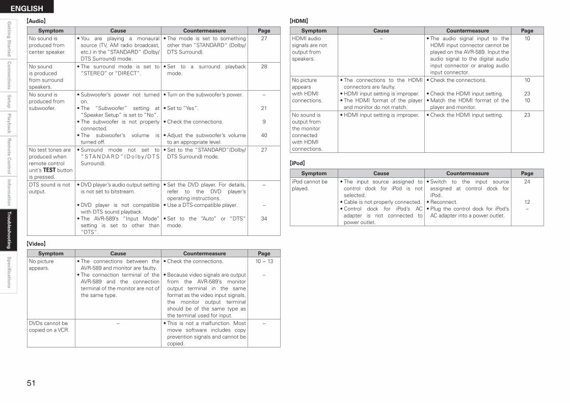
Symptom Cause Countermeasure PageNo sound is produced from center speaker.
• You are playing a monaural source (TV, AM radio broadcast, etc.) in the “STANDARD” (Dolby/DTS Surround) mode.
• The mode is set to something other than “STANDARD” (Dolby/DTS Surround).
27
No sound is produced from surround speakers.
• The surround mode is set to “STEREO” or “DIRECT”.
• Set to a surround playback mode.
28
No sound is produced from subwoofer.
• Subwoofer’s power not turned on.
• The “Subwoofer” setting at “Speaker Setup” is set to “No”.
• The subwoofer is not properly connected.
• The subwoofer’s volume is turned off.
• Turn on the subwoofer’s power.
• Set to “Yes”.
• Check the connections.
• Adjust the subwoofer’s volume to an appropriate level.
–
21
9
40
No test tones are produced when remote control unit’s TEST button is pressed.
• Surround mode not set to “ S TA N DA R D ” ( D o l b y / D T S Surround).
• Set to the “STANDARD”(Dolby/DTS Surround) mode.
27
DTS sound is not output.
• DVD player’s audio output setting is not set to bitstream.
• DVD player is not compatible with DTS sound playback.
• The AVR-589’s “Input Mode” setting is set to other than “DTS”.
• Set the DVD player. For details, refer to the DVD player’s operating instructions.
• Use a DTS-compatible player.
• Set to the “Auto” or “DTS” mode.
–
–
34
GAudioH
Symptom Cause Countermeasure PageNo picture appears.
• The connections between the AVR-589 and monitor are faulty.
• The connection terminal of the AVR-589 and the connection terminal of the monitor are not of the same type.
• Check the connections.
• Because video signals are output from the AVR-589’s monitor output terminal in the same format as the video input signals, the monitor output terminal should be of the same type as the terminal used for input.
10 ~ 13
–
DVDs cannot be copied on a VCR.
– • This is not a malfunction. Most movie software includes copy prevention signals and cannot be copied.
–
GVideoH
Symptom Cause Countermeasure Page
iPod cannot be played.
• The input source assigned to control dock for iPod is not selected.
• Cable is not properly connected.• Control dock for iPod’s AC
adapter is not connected to power outlet.
• Switch to the input source assigned at control dock for iPod.
• Reconnect.• Plug the control dock for iPod’s
AC adapter into a power outlet.
24
12–
GiPodH
Symptom Cause Countermeasure PageHDMI audio signals are not output from speakers.
– • The audio signal input to the HDMI input connector cannot be played on the AVR-589. Input the audio signal to the digital audio input connector or analog audio input connector.
10
No picture appears with HDMI connections.
• The connections to the HDMI connectors are faulty.
• HDMI input setting is improper.• The HDMI format of the player
and monitor do not match.
• Check the connections.
• Check the HDMI input setting.• Match the HDMI format of the
player and monitor.
10
2310
No sound is output from the monitor connected with HDMI connections.
• HDMI input setting is improper. • Check the HDMI input setting. 23
GHDMIH
��
Gettin
g S
tartedC
on
nectio
ns
Setu
pP
layback
Rem
ote C
on
trol
Info
rmatio
nT
rou
blesh
oo
ting
ENGLISH
Sp
ecificatio
ns

Symptom Cause Countermeasure Page“CHECK SR TUNER” is displayed in the SIRIUS mode.
• The Sirius Tuner unit is not connected.
• Check that the connections are correct.
14
“ANTENNA ERROR” is displayed in the SIRIUS mode.
• If the Sirius Tuner is not connected, it will be broken.
• Check that the connections are correct.
14
“NO SIGNAL” is displayed in the SIRIUS mode.
• The signal cannot be received. • Reposition your SiriusConnect Home Tuner antenna.
37
“INVALID CHANNEL” is displayed in the SIRIUS mode.
• Channel is not present. • Select another channel. 37
“NO CH AVAILABLE” is displayed in the SIRIUS mode.
• Even searching categories, if none of the channels are present, the “Parental Lock” is on (locked).
• Please search for other categories.
37
“ACQUIRING” is displayed in the SIRIUS mode.
• The selected channel is not currently broadcasting.
• Displays while SiriusConnect Home Tuner is connected.
• Select another channel. 37
“Call SIRIUS”z is displayed in the SIRIUS mode.
• Channels are not subscribed to. • If you subscribe to the channel, you can receive the channel.
–
“SUB UPDATED” is displayed in the SIRIUS mode.
• While updating contract information.
– –
“Code? [ ]” is displayed in the SIRIUS mode.
• Selected channels are locked. • Please insert pass word (4 digits) into “[ ]”.
25
GSIRIUS Satellite RadioH
z : After scroll displays “Call 888-539-....” twice, displays “Call SIRIUS”.
n Audio section • Power amplifier Rated output: Front (A, B): 75 W + 75 W (8 Ω/ohms, 20 Hz ~ 20 kHz with 0.08 % T.H.D.) 110 W + 110 W (6 Ω/ohms, 1 kHz with 0.7 % T.H.D.) Center: 75 W (8 Ω/ohms, 20 Hz ~ 20 kHz with 0.08 % T.H.D.) 110 W (6 Ω/ohms, 1 kHz with 0.7 % T.H.D.) Surround: 75 W + 75 W (8 Ω/ohms, 20 Hz ~ 20 kHz with 0.08 % T.H.D.) 110 W + 110 W (6 Ω/ohms, 1 kHz with 0.7 % T.H.D.) Output connectors: Front: A or B 16 ~ 16 Ω/ohms A + B 12 ~ 16 Ω/ohms Center, Surround: 16 ~ 16 Ω/ohms • Analog Input sensitivity / Input impedance: 200 mV / 47 kΩ/kohms Frequency response: 10 Hz ~ 100 kHz — +1, –3 dB (DIRECT mode) S/N: 98 dB (IHF-A weighted, DIRECT mode)
n Video section • Standard video connectors Input / output level and impedance: 1 Vp-p, 75 Ω/ohms Frequency response: 5 Hz ~ 10 MHz — +1, –3 dB • S-Video connectors Input / output level and impedance: Y (brightness) signal — 1 Vp-p, 75 Ω/ohms C (color) signal — 0.286 Vp-p, 75 Ω/ohms Frequency response: 5 Hz ~ 10 MHz — +1, –3 dB • Color component video connectors Input / output level and impedance: Y (brightness) signal — 1 Vp-p, 75 Ω/ohms PB / CB signal — 0.7 Vp-p, 75 Ω/ohms PR / CR signal — 0.7 Vp-p, 75 Ω/ohms Frequency response: 5 Hz ~ 30 MHz — +0, –3 dB
n Tuner section [FM] [AM] (note: µV at 75 Ω/ohms, 0 dBf = 1 x 10-15 W) Receiving Range: 87.5 MHz ~ 107.9 MHz 520 kHz ~ 1710 kHz Usable Sensitivity: 1.0 µV (11.2 dBf) 18 µV 50 dB Quieting Sensitivity: MONO 1.6 µV (15.3 dBf) STEREO 23 µV (38.5 dBf) S/N (IHF-A): MONO 77 dB STEREO 72 dB Total harmonic Distortion (at 1 kHz): MONO 0.15 % STEREO 0.3 %
n General Power supply: AC 120 V, 60 Hz Power consumption: 3.9 A 0.3 W (Standby) Maximum external dimensions: 434 (W) x 171 (H) x 377 (D) mm (17-3/32” x 6-47/64” x 14-27/32”) Weight: 10.8 kg (23 lbs 13 oz)
n Remote control unit (RC-1104) Batteries: R6/AA Type (two batteries) Maximum external dimensions: 52 (W) x 243 (H) x 21 (D) mm (2-3/64” x 9-9/16” x 53/64”) Weight: 184 g (Approx. 6.5 oz) (including batteries)
z For purposes of improvement, specifications and design are subject to change without notice.
Specifications
��
Gettin
g S
tartedC
on
nectio
ns
Setu
pP
layback
Rem
ote C
on
trol
Info
rmatio
nT
rou
blesh
oo
ting
ENGLISHS
pecifi
cation
s

PRESET CODE�
Blu-Ray Disc Player / DVD PlayerA Aiwa 009
D Denon 014, [111]z, 121
H Hitachi 010
J JVC 006, 011
K Konka 012, 013
M Magnavox 005Mitsubishi 004
P Panasonic 014Philips 005, 015, 016, 017Pioneer 003, 008
S Sanyo 018Sony 002, 019, 020
T Toshiba 001, 021, 022
Z Zenith 023
VDPD Denon 028, 029, 112
M Magnavox 026Mitsubishi 028
P Panasonic 029, 030Philips 026Pioneer 028, 031
R RCA 032
S Sony 033, 034, 035, 036
VCRA Admiral 081
Aiko 095Aiwa 009
Akai 026, 027, 070, 072, 082, 083, 084
Alba 055Amstrad 009ASA 042Asha 087Audio Dynamic 005, 085Audiovox 088
Beaumark 087Broksonic 086, 093
C Calix 088Candle 006, 087, 088, 089, 090Canon 049, 057Capehart 025, 055, 056, 071Carver 015CCE 095
Citizen 006, 007, 087, 088, 089, 090, 095
Craig 007, 087, 088, 091, 115
Curtis Mathes 006, 049, 073, 080, 087, 090, 092
Cybernex 087
D Daewoo 025, 055, 059, 074, 089, 093, 095, 096
Daytron 025, 055DBX 005, 085Dumont 053Dynatech 009
E Electrohome 001, 088, 097Electrophonic 088
Emerson001, 009, 017, 027, 086, 088, 089, 092, 093, 097, 100, 101, 102, 103, 104, 117
F Flsher 009, 028, 031, 053, 054, 091, 099, 115
G GE 007, 011, 049, 050, 051, 052, 073, 080, 087
Go Video 047, 048Goldstar 000, 006, 012, 062, 088Gradiente 094Grundig 042
H Harley Davidson 094Harman Kardon 040, 062Hi-Q 091
Hitachi 009, 013, 023, 026, 058, [108]z, 109, 110, 111
J JC Penny 004, 005, 007, 023, 028, 049, 062, 085, 087, 088
Jensen 013, 026
JVC 004, 005, 006, 026, 029, 043, 044, 045, 046, 085
K Kenwood 004, 005, 006, 026, 029, 033, 045, 085, 090
Kodak 088
L Lloyd 009, 094LXI 088
M Magnavox 015, 016, 042, 049, 063, 106Magnin 087
Marantz 004, 005, 006, 015, 042, 049, 085, 090
Marta 088MEI 049
Memorex 009, 033, 049, 053, 060, 081, 087, 088, 091, 094, 115
Metz 123, 124, 125, 126, 127, 128MGA 001, 017, 027, 041, 097MGN Technology 087Midland 011Minolta 013, 023
Mitsubishi001, 003, 008, 013, 014, 017, 027, 029, 039, 040, 041, 045, 097
Motorola 081
Montgomery Ward 001, 002, 007, 009, 049, 063, 081, 115, 117
MTC 009, 087, 094
Multitech 007, 009, 011, 087, 090, 094
N NAD 038
NEC 004, 005, 006, 018, 026, 029, 045, 061, 062, 085
Nikko 088Noblex 087
O Optimus 081, 088Optonica 021
P Panasonic 024, 049, 064, 066, 067, 068, 069, 107
Perdio 009Pentax 009, 013, 023, 058, 090Philco 015, 016, 049Philips 015, 021, 042, 049, 105Pilot 088
Pioneer 005, 013, 029, 036, 037, 038, 045, 085
Portland 025, 055, 090Proscan 063, 080Pulsar 060
Q Quartz 033Quasar 034, 035, 049
R Radio Shack 001, 002, 021, 081, 087, 088, 091, 094, 097, 098, 115
Radix 088Randex 088
RCA 007, 013, 019, 023, 058, 063, 064, 065, 073, 080, 082, 087
Realistic009, 021, 031, 033, 049, 053, 081, 087, 088, 091, 094, 097, 098
Ricoh 055
S Salora 033, 041
Samsung 007, 011, 051, 059, 070, 083, 087, 089, 113
Sanky 081
Sansui 005, 026, 029, 045, 061, 085, 114
Sanyo 032, 033, 053, 087, 091, 115, 116
SBR 042Scott 017, 020, 086, 089, 093, 117
Sears 013, 023, 028, 031, 033, 053, 054, 088, 091, 098, 099, 115
Sentra 055Sharp 001, 002, 021, 097Shogun 087
Sony 075, 076, 077, 078, 079, 121, 122
STS 023
Sylvania 009, 015, 016, 017, 041, 049, 094
Symphonic 009, 094
T Tandy 009Tashiko 009, 088Tatung 004, 026, 030
Teac 004, 009, 026, 094Technics 024, 049TMK 087, 092
Toshiba 013, 017, 020, 041, 059, 089, 098, 099, 117
Totevision 007, 087, 088
U Unirech 087
V Vecrtor Research 005, 062, 085, 089, 090Victor 005, 045, 046, 085Video Concepts 005, 027, 085, 089, 090Videosonic 007, 087
W Wards 013, 021, 023, 087, 088, 089, 091, 094, 097, 118, 119, 120
X XR-1000 094
Y Yamaha 004, 005, 006, 026, 062, 085
Z Zenith 060, 078, 079
TelevisionA Admiral 045, 121
Adventura 122Aiko 054Akai 016, 027, 046Alleron 062A-Mark 007Amtron 061Anam 006, 007, 036Anam National 061, 147
AOC 003, 007, 033, 038, 039, 047, 048, 049, 133
Archer 007Audiovox 007, 061
B Bauer 155Belcor 047Bell & Howell 045, 118Bradford 061Brockwood 003, 047
C Candle 003, 030, 031, 032, 038, 047, 049, 050, 122
Capehart 003Celebrity 046Circuit City 003
Citizen029, 030, 031, 032, 034, 038, 047, 049, 050, 054, 061, 095, 122, 123
Concerto 031, 047, 049Colortyme 003, 047, 049, 135Contec 013, 051, 052, 061Cony 051, 052, 061Craig 004, 061Crown 029
Curtis Mathes 029, 034, 038, 044, 047, 049, 053, 095, 118
D Daewoo 027, 029, 039, 048, 049, 054, 055, 106, 107, 137
Daytron 003, 049Dimensia 044Dixi 007, 015, 027
E Electroband 046Electrohome 029, 056, 057, 058, 147Elta 027
Emerson 029, 051, 059, 060, 061, 062, 118, 123, 124, 139, 148
Envision 038Etron 027
F Fisher 014, 021, 063, 064, 065, 118Formenti 155Fortress 012Fujitsu 004, 062Funai 004, 062Futuretech 004
G GE 020, 036, 037, 040, 044, 058, 066, 088, 119, 120, 125, 147
Goldstar000, 015, 029, 031, 039, 048, 051, 056, 057, 067, 068, 069, 116
Grundy 062
H Hitachi 029, 031, 051, 052, 070, 111, 112, 113, 124, [134]*
Hitachi Pay TV 151
I Infinity 017, 071
J Janeil 122JBL 017, 071
JC Penny020, 034, 039, 040, 041, 044, 048, 050, 058, 066, 069, 076, 088, 090, 095, 125, 136, 159
JCB 046
JVC 019, 051, 052, 072, 073, 091, 117, 126
K Kawasho 018, 046Kenwood 038, 056, 057Kloss 010, 032Kloss Novabeam 005, 122, 127, 131KTV 074, 123
L Loewe 071logik 144Luxman 031
LXI008, 014, 017, 024, 040, 044, 063, 071, 075, 076, 077, 118, 125
M Magnavox005, 010, 017, 030, 033, 038, 050, 056, 071, 078, 079, 085, 089, 108, 109, 110, 127, 131, 132, 145
Marantz 015, 017, 071, 080Matsui 027Memorex 014, 027, 045, 083, 118, 144Metz 160, 161, 162, 163
List of preset codes / Liste de codes préréglés
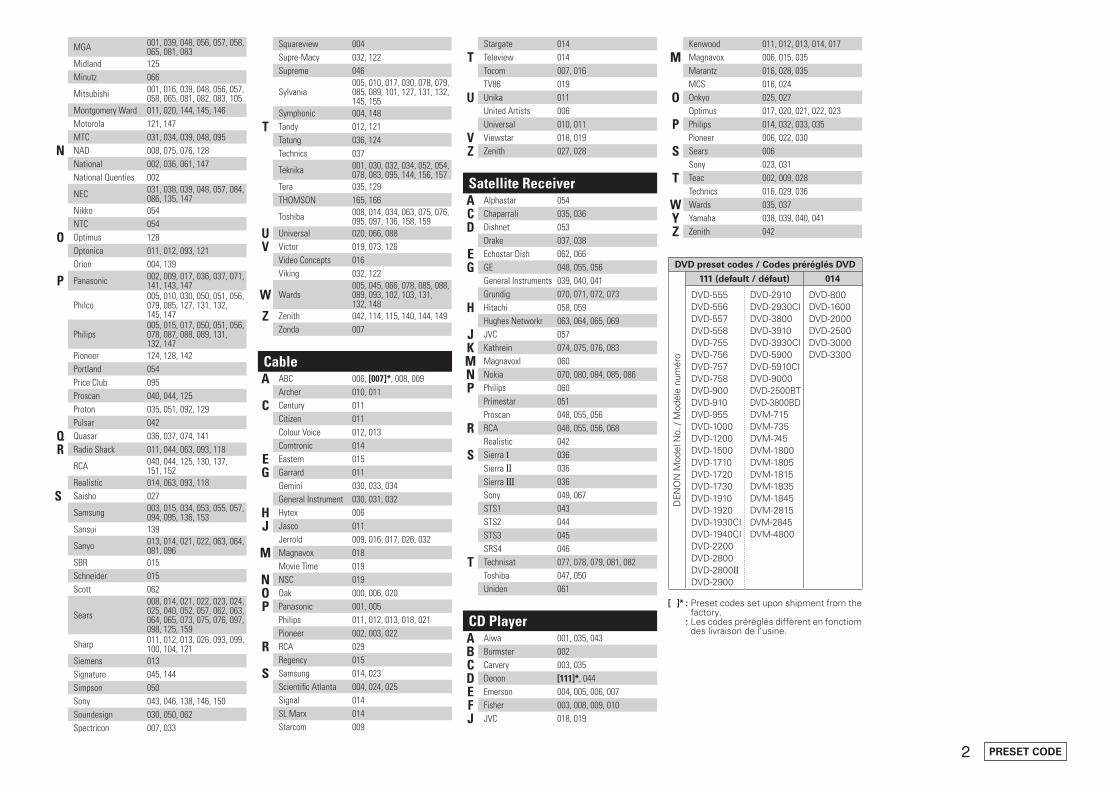
� PRESET CODE
MGA 001, 039, 048, 056, 057, 058, 065, 081, 083
Midland 125Minutz 066
Mitsubishi 001, 016, 039, 048, 056, 057, 058, 065, 081, 082, 083, 105
Montgomery Ward 011, 020, 144, 145, 146Motorola 121, 147MTC 031, 034, 039, 048, 095
N NAD 008, 075, 076, 128National 002, 036, 061, 147National Quenties 002
NEC 031, 038, 039, 048, 057, 084, 086, 135, 147
Nikko 054NTC 054
O Optimus 128Optonica 011, 012, 093, 121Orion 004, 139
P Panasonic 002, 009, 017, 036, 037, 071, 141, 143, 147
Philco005, 010, 030, 050, 051, 056, 079, 085, 127, 131, 132, 145, 147
Philips005, 015, 017, 050, 051, 056, 078, 087, 088, 089, 131, 132, 147
Pioneer 124, 128, 142Portland 054Price Club 095Proscan 040, 044, 125Proton 035, 051, 092, 129Pulsar 042
Q Quasar 036, 037, 074, 141
R Radio Shack 011, 044, 063, 093, 118
RCA 040, 044, 125, 130, 137, 151, 152
Realistic 014, 063, 093, 118
S Saisho 027
Samsung 003, 015, 034, 053, 055, 057, 094, 095, 136, 153
Sansui 139
Sanyo 013, 014, 021, 022, 063, 064, 081, 096
SBR 015Schneider 015Scott 062
Sears008, 014, 021, 022, 023, 024, 025, 040, 052, 057, 062, 063, 064, 065, 073, 075, 076, 097, 098, 125, 159
Sharp 011, 012, 013, 026, 093, 099, 100, 104, 121
Siemens 013Signature 045, 144Simpson 050Sony 043, 046, 138, 146, 150Soundesign 030, 050, 062Spectricon 007, 033
Squareview 004Supre-Macy 032, 122Supreme 046
Sylvania005, 010, 017, 030, 078, 079, 085, 089, 101, 127, 131, 132, 145, 155
Symphonic 004, 148
T Tandy 012, 121Tatung 036, 124Technics 037
Teknika 001, 030, 032, 034, 052, 054, 078, 083, 095, 144, 156, 157
Tera 035, 129THOMSON 165, 166
Toshiba 008, 014, 034, 063, 075, 076, 095, 097, 136, 158, 159
U Universal 020, 066, 088
V Victor 019, 073, 126Video Concepts 016Viking 032, 122
W Wards005, 045, 066, 078, 085, 088, 089, 093, 102, 103, 131, 132, 148
Z Zenith 042, 114, 115, 140, 144, 149Zonda 007
CableA ABC 006, [007]*, 008, 009
Archer 010, 011
C Century 011Citizen 011Colour Voice 012, 013Comtronic 014
E Eastern 015
G Garrard 011Gemini 030, 033, 034General Instrument 030, 031, 032
H Hytex 006
J Jasco 011Jerrold 009, 016, 017, 026, 032
M Magnavox 018Movie Time 019
N NSC 019
O Oak 000, 006, 020
P Panasonic 001, 005Philips 011, 012, 013, 018, 021Pioneer 002, 003, 022
R RCA 029Regency 015
S Samsung 014, 023Scientific Atlanta 004, 024, 025Signal 014SL Marx 014Starcom 009
Stargate 014
T Teleview 014Tocom 007, 016TV86 019
U Unika 011United Artists 006Universal 010, 011
V Viewstar 018, 019
Z Zenith 027, 028
Satellite ReceiverA Alphastar 054
C Chaparrali 035, 036
D Dishnet 053Drake 037, 038
E Echostar Dish 062, 066
G GE 048, 055, 056General Instruments 039, 040, 041Grundig 070, 071, 072, 073
H Hitachi 058, 059Hughes Networkr 063, 064, 065, 069
J JVC 057
K Kathrein 074, 075, 076, 083
M Magnavoxl 060
N Nokia 070, 080, 084, 085, 086
P Philips 060Primestar 051Proscan 048, 055, 056
R RCA 048, 055, 056, 068Realistic 042
S Sierra I 036Sierra g 036Sierra III 036Sony 049, 067STS1 043STS2 044STS3 045SRS4 046
T Technisat 077, 078, 079, 081, 082Toshiba 047, 050Uniden 061
CD PlayerA Aiwa 001, 035, 043
B Burmster 002
C Carvery 003, 035
D Denon [111]*, 044
E Emerson 004, 005, 006, 007
F Fisher 003, 008, 009, 010
J JVC 018, 019
Kenwood 011, 012, 013, 014, 017
M Magnavox 006, 015, 035Marantz 016, 028, 035MCS 016, 024
O Onkyo 025, 027Optimus 017, 020, 021, 022, 023
P Philips 014, 032, 033, 035Pioneer 006, 022, 030
S Sears 006Sony 023, 031
T Teac 002, 009, 028Technics 016, 029, 036
W Wards 035, 037
Y Yamaha 038, 039, 040, 041
Z Zenith 042
DVD preset codes / Codes préréglés DVD
DE
NO
N M
odel
No.
/ M
odél
e nu
mér
o
111 (default / défaut) 014
DVD-555DVD-556DVD-557DVD-558DVD-755DVD-756DVD-757DVD-758DVD-900DVD-910DVD-955DVD-1000DVD-1200DVD-1500DVD-1710DVD-1720DVD-1730DVD-1910DVD-1920DVD-1930CIDVD-1940CIDVD-2200DVD-2800DVD-2800gDVD-2900
DVD-2910DVD-2930CIDVD-3800DVD-3910DVD-3930CIDVD-5900DVD-5910CIDVD-9000DVD-2500BTDVD-3800BDDVM-715DVM-735DVM-745DVM-1800DVM-1805DVM-1815DVM-1835DVM-1845DVM-2815DVM-2845DVM-4800
DVD-800DVD-1600DVD-2000DVD-2500DVD-3000DVD-3300
[ ]* : Preset codes set upon shipment from the factory.
*[ ] : Les codes préréglés diffèrent en fonctiom des livraison de l’usine.

Denon Brand Company, D&M Holdings Inc.Printed in China 5411 10042 105D
www.denon.com

Ow
ner’s M
an
ua
l / safety In
struc
tIOn
s / cOM
plIan
ce InfO
rMatIO
n
HOrIZOn MCS 905.1 surround speaker system
españolMCS 90Sistema Multicanal Boston
francaisMCS 90Haut-parleur multivoix Boston
a Boston p.O
.p. productM
ake it your own...

2
Important Safety Instructions
This symbol found on the apparatusindicates hazards arising from danger-ous voltages.
This symbol found on the apparatus
indicates the user should read all safety
statements found in the user manual.
This symbol found on the apparatus
indicates double insulation.
WARNING! To reduce the risk of �re or electric shock, do not expose this apparatus to rain ormoisture.
This symbol found on the apparatus indi-cates that the apparatus must be placed in aseparate collection facility for electronicwaste and not disposed of with householdwaste.
1. Read these instructions.2. Keep these instructions.3. Heed all warnings.4. Follow all instructions.5. Do not use this apparatus near water.6. Clean only with dry cloth.7. Do not block any ventilation openings. Install in
accordance with the manufacturer's instructions.8. Do not install near any heat sources such as radi-
ators, heat registers, stoves, or other apparatus(including ampli�ers) that produce heat.
9. Do not defeat the safety purpose of the polarizedor gr ounding-type plug. A polarized plug hastwo blades with one wider than the other. A grounding type plug has two blades and athird grounding prong. The wide blade or thethird prong are provided for your safety. If theprovided plug does not �t into your outlet,consult an electrician for replacement of theobsolete outlet.
10. Protect the power cord from being walked on or pinched particularly at plugs, conveniencereceptacles, and the point where they exitfrom the apparatus.
11. Only use attachments/accessories speci�ed bythe manufacturer.
12. Unplug this apparatus during lightning stormsor when unused for long periods of time.
13. Refer all servicing to quali�ed service personnel.Servicing is required when the apparatus hasbeen damaged in any way, such as power sup-ply cord or plug is damaged, liquid has been
spilled or objects have fallen into the appara-tus, the apparatus has been exposed to rain ormoisture, does not operate normally, or hasbeen dropped.
14. Maintain a minimum distance of 50 mm aroundthe front, rear and sides of the apparatus for su�cient ventilation. The ventilation should notbe impeded by covering the ventilation open-ings or placing on or around the apparatusitems such as newspapers, table-cloths, cur-tains, etc.
15. No naked �ame sources, such as lighted candles, should be placed on the apparatus.
16. The apparatus shall not be exposed to drip-ping or splashing. No objects �lled with liq- uids, such as vases, shall be placed on theapparatus.
17. Either the power inlet connector on the rear ofthe apparatus or the power plug at the wallmust remain accessible, to be able to discon-nect power from the apparatus.
18. To completely disconnect this apparatus fromthe AC Mains, disconnect the power supplycord plug from the AC receptacle.
19. The mains plug of the power supply cord shallremain readily operable.
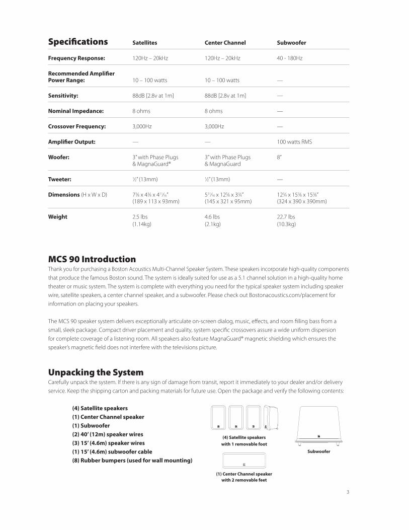
3
MCS 90 IntroductionThank you for purchasing a Boston Acoustics Multi-Channel Speaker System. These speakers incorporate high-quality components that produce the famous Boston sound. The system is ideally suited for use as a 5.1 channel solution in a high-quality home theater or music system. The system is complete with everything you need for the typical speaker system including speaker wire, satellite speakers, a center channel speaker, and a subwoofer. Please check out Bostonacoustics.com/placement for information on placing your speakers.
The MCS 90 speaker system delivers exceptionally articulate on-screen dialog, music, effects, and room filling bass from a small, sleek package. Compact driver placement and quality, system specific crossovers assure a wide uniform dispersion for complete coverage of a listening room. All speakers also feature MagnaGuard® magnetic shielding which ensures the speaker’s magnetic field does not interfere with the televisions picture.
Unpacking the SystemCarefully unpack the system. If there is any sign of damage from transit, report it immediately to your dealer and/or delivery service. Keep the shipping carton and packing materials for future use. Open the package and verify the following contents:
(4) Satellite speakers (1) Center Channel speaker (1) Subwoofer (2) 40’ (12m) speaker wires (3) 15’ (4.6m) speaker wires (1) 15’ (4.6m) subwoofer cable (8) Rubber bumpers (used for wall mounting)
(1) Center Channel speaker with 2 removable feet
Subwoofer
Specifications Satellites Center Channel Subwoofer
Frequency Response: 120Hz – 20kHz 120Hz – 20kHz 40 - 180Hz
Recommended Amplifier Power Range: 10 – 100 watts 10 – 100 watts —
Sensitivity: 88dB [2.8v at 1m] 88dB [2.8v at 1m] —
Nominal Impedance: 8 ohms 8 ohms —
Crossover Frequency: 3,000Hz 3,000Hz —
Amplifier Output: — — 100 watts RMS
Woofer: 3” with Phase Plugs 3” with Phase Plugs 8” & MagnaGuard® & MagnaGuard
Tweeter: 1⁄2” (13mm) 1⁄2” (13mm) —
Dimensions (H x W x D) 73⁄8 x 43⁄8 x 411⁄16” 511⁄16 x 125⁄8 x 33⁄4” 123⁄4 x 153⁄8 x 153⁄8” (189 x 113 x 93mm) (145 x 321 x 95mm) (324 x 390 x 390mm)
Weight 2.5 lbs 4.6 lbs 22.7 lbs (1.14kg) (2.1kg) (10.3kg)
(4) Satellite speakers with 1 removable foot

4
Placement OptionsThe MCS 90 satellites and center channel are easily placed on a tabletop or wall-mounted. The speakers are configured for tabletop use when you first unpack the system. The foot installed on the rear of the speaker will keep it upright.
The MCS 90 satellites and center channel are designed to easily mount on the wall using the keyhole slot(s) on the back of the speaker. When mounting the speakers to the wall use the supplied rubber bumpers. You must remove the attached foot to wall-mount your speakers. Remove the thumbscrew from the back of the foot. It is slotted for easy removal with a screwdriver or a coin.
The keyhole mounting option is similar to hanging a picture frame on a wall. Install a #8 screw (not included) into the sheetrock, making sure to go into a stud, and hang the speaker onto the screw head. If a stud is not available, a sheetrock anchor should be used to support the weight of the speaker. It is advisable to connect the speaker wire prior to wall-mounting.
NOTE: Because there are so many different kinds of surfaces on which the speakers could be mounted. There is no one type of fastener that we could supply that would work in all the possible situations. So taking into account the surface the speaker is being mounted on, acquire the appropriate type of fasteners. If you’re not sure what type of fastener to use, take the mounting bracket to a friendly hardware store, tell them about the wall you’re mounting the speaker on, and ask them to recommend an appropriate fastener. Keep in mind the weight of the speaker.
Speaker ConnectionsAfter your speakers are properly placed, you are ready to wire your system. First, turn off all system power. Use the speaker wire included with the system to make your connections. For longer distances, #16 or #18 gauge wire available from your dealer should be used. Please see the illustration for guidance con-necting the wires to the MCS 90 satellites and center channel.
For connection to your receiver please refer to its owner’s manual.
Important!To ensure the best performance observe polarities when making speaker connections, as shown in the illustration. Connect each + terminal on the back of the amplifier or receiver to the respective + (red) terminal on each speaker. Connect the – (black) terminals in the same way. If the connections are not made correctly it can cause poor bass response and imaging. Also, to avoid short circuits that may damage your equipment be careful not to let any of the bare wires touch each other.
Subwoofer ConnectionsTurn off all power. Use the subwoofer cable included with your system to connect the subwoofer to your receivers Subwoofer or LFE Output. Connect the other end to the “Line In” on the back of the Subwoofer.
+ –
+ –
+ Red – Black

5
Subwoofer ControlsPower OnPlug the subwoofer’s AC cord into a wall outlet. We do not recommend using use the outlets on the back of the receiver. The subwoofer features auto on/standby. An LED indicator next to the volume control indicates what mode the subwoofer is in.
RED = STANDBY (No signal detected, Amp Off ) GREEN = ON (Signal detected, Amp On)
The subwoofer will automatically enter the Standby mode after several minutes when no signal is detected from your system. The subwoofer will then power ON instantly when a signal is detected.
Volume ControlBegin by adjusting the Subwoofer Volume Control to the 11 o’clock position. Further adjust the Subwoofer Volume Control until you hear a match in volume between the main speakers and subwoofer. Ideally, bass response should not overpower the room but rather be adjusted so there is a natural blend across the entire musical range.
OperationWhen using the MCS 90 in a Dolby® Digital or DTS™ home theater system, make sure all speakers are set to “Small”. When using the system in a Dolby Pro Logic® home theater system, make sure the receiver’s center channel mode is set to “Normal.”
Some Dolby Digital equipped receivers/processors offer different setup options for each source or surround mode (e.g., CD-stereo, videotape, Dolby Digital, Pro Logic®). In each case, follow your equipment’s instructions to ensure that the subwoofer output is turned on and that the speakers are set to “Small” in each mode.
If your receiver has adjustable crossover settings, we recommend the subwoofer crossover be set at 150Hz.
Refer to the owner’s manual for your AV receiver for any additional recommendations on system operation.
Maintenance and ServiceThe satellite and subwoofer enclosures may be cleaned using a soft cloth to remove fingerprints or to wipe off dust. All wiring connections should be inspected and cleaned or remade at least once a year.
If a problem does occur, make sure that all connections are properly made, secure and clean. If a problem occurs in one loud-speaker, rewire that speaker in a different location within the system. Should the problem persist in this speaker the problem is within the speaker. If the speaker sounds fine in the new position it is a strong indication of a more in depth issue with the electronics in the system. In the event that your MCS 90 ever needs service, contact your local Boston Acoustics dealer or visit www.Bostona.com for a list of dealers in your area.
If your subwoofer does not play, check that all the connectors on the cables are making proper contact and that the AC plug is connected to a “live” receptacle.
MCS 90
LED indicator

6
Limited WarrantyBoston Acoustics warrants to the original purchaser of our MCS 90 system that it will be free of defects in materials and workmanship in its mechanical parts for a period of 5 years from the date of purchase. The warranty period for the electrical components of MCS 90 is 1 year.
Your responsibilities are to install and use them according to the instructions supplied, to provide safe and secure transporta-tion to an authorized Boston Acoustics service representative, and to present proof of purchase in the form of your sales slip when requesting service.
Excluded from this warranty is damage that results from abuse, misuse, improper installation, accidents, shipping, or repairs/modifications by anyone other than an authorized Boston Acoustics service representative.
This warranty is limited to the Boston Acoustics product and does not cover damage to any associated equipment. This warranty does not cover the cost of removal or reinstallation. This warranty is void if the serial number has been removed or defaced. This warranty gives you specific legal rights, and you may also have other rights which vary from state to state.
If Service Seems NecessaryFirst, contact the dealer from whom you purchased the product. If that is not possible, write to:
Boston Acoustics, Inc. 300 Jubilee Drive Peabody, MA 01960 USA
Or contact us via e-mail at: [email protected]
We will promptly advise you of what action to take. If it is necessary to return your MCS 90 to the factory, please ship it prepaid. After it has been repaired, we will return it freight prepaid in the United States and Canada.
For EU Customers OnlyThis symbol found on the product indicates that the product must not be disposed of with household waste. Instead, it may be placed in a separate collection facility for electronic waste or returned to a retailer when pur-chasing similar product. The producer paid to recycle this product. Doing this contributes to reuse and recycling, minimizes adverse effects on the environment and human health and avoids any fines for incorrect disposal.
Boston Acoustics continually strives to update and improve its products. The specifications and construction details are subject to change without notice.

7
Instrucciones de Seguridad Importantes
Este símbolo que aparece en el aparato indica riesgos derivados de voltajes peligrosos.
Este símbolo que aparece en el aparato indica que el usuario debe leer todas las declaracio-nes de seguridad que aparecen en el manual del usuario.
Este símbolo que aparece en el aparato indica la presencia de un doble aislamiento.
1. Lea estas instrucciones.2. Conserve estas instrucciones.3. Haga caso de todas las advertencias.4. Siga todas las instrucciones.5. No utilice este aparato cerca del agua.6. Límpielo sólo con un trapo seco.7. No tapone ninguna apertura de ventilación. Instálelo de
acuerdo con las instrucciones del fabricante.8. No lo instale cerca de ninguna fuente de calor, tales como
radiadores, rejillas de calefacción, estufas u otros aparatos (incluidos ampli�cadores) que produz-can calor.
9. No anule el propósito de seguridad del enchufe pola-rizado o del tipo puesta a tierra. Un enchufe polari-zado tiene dos púas con una de ellas más ancha que la otra. Un enchufe del tipo puesta a tierra tiene dos púas y una tercera púa de puesta a tierra. La púa an-cha o la tercera púa se proporciona para su seguridad. Si el enchufe que se suministra no encaja en su toma de pared, consulte con un electricista para que susti-tuya la toma de pared obsoleta.
10. Proteja el cable de alimentación para evitar que sea pisado o quede pinzado, en particular en los enchufes, las tomas de corriente, y en el punto en el cual sale del aparato.
11. Utilice sólo las conexiones/accesorios especi�cados por el fabricante.
12. Desenchufe este aparato durante las tormentas eléc-tricas o cuando no vaya a utilizarse durante largos periodos de tiempo.
13. Remita todo el servicio al personal de servicio cuali-�cado. Se requiere servicio cuando el aparato ha sido dañado de algún modo, por ejemplo si el cable de alimentación o el enchufe están dañados, si se ha ver-tido líquido o han caído objetos dentro del aparato, si el aparato se ha expuesto a la lluvia o a la humedad, si no funciona normalmente, o se ha caído.
14. Mantenga una distancia mínima de 50 mm alrededor de la
parte delantera, trasera y de los laterales del aparato para tener una ventilación su�ciente. La ven-tilación no debe quedar obstruida mediante la cober-tura de las aperturas de ventilación o la colocación sobre o alrededor del aparato de elementos tales co-mo periódicos, tapetes, cortinas, etc.
15. No deben colocarse sobre el aparato fuentes de lla-mas desnudas, tales como velas encendidas.
16. No debe exponerse el aparato a goteo o a salpicadu-ras. No deben colocarse sobre el aparato objetos llenos de líquidos, tales como jarrones.
17. Tanto el conector de entrada de energía de la parte trasera del aparato como el enchufe de pared deben ser accesibles, para poder desconectar la energía del aparato.
18. Para desconectar completamente este aparato de la red de CA, desconecte el enchufe del cable de ali-mentación de la toma de CA.
19. La toma de red del cable de alimentación debe tener siempre un fácil acceso.
¡ADVERTENCIA! Para reducir el riesgo de incendio o de descarga eléctrica, no exponga este aparato a la lluvia o a la humedad.
Este símbolo que aparece en el aparato indi-ca que el aparato debe colocarse en un punto de recogida separada para desechos electró-nicos y que no debe desecharse con la basura doméstica.
EnESPAñOL

8
Introducción al MCS 90 Gracias por comprar un Sistema de Altavoces de Solución Multicanal de Boston Acoustics. Estos altavoces incorporan componen-tes de alta calidad que crean el famoso sonido Boston. El sistema está adaptado de forma adecuada para su utilización como una solución de canales 5.1 en un cine en casa o en un sistema musical de alta calidad. Se trata de un sistema completo con todo lo que se puede necesitar para un sistema típico de altavoces, lo que incluye cable para altavoces, altavoces satélites, un altavoz de canal central y un subwoofer. Consulte en Bostona-coustics.com la información sobre la colocación de sus altavoces.
El sistema de altavoces MCS 90 presenta un diálogo en pantalla excepcionalmente articulado, música, efectos y graves en-volventes en un conjunto pequeño y elegante. La colocación compacta de cada altavoz y las frecuencias de cruce de calidad y específicas del sistema asegu-ran una amplia dispersión uniforme para una cobertura total de la sala de escucha. Todos los altavoces presentan también el blindaje magnéti-co MagnaGuard® que asegura que el campo magnético del altavoz no interfiera con las imágenes de televisión.
Desembalaje del SistemaDesembale cuidadosamente el sistema. Si hay alguna señal de daños debidos al transporte, informe de ello inmediatamente a su distribuidor y/o a su servicio de entrega. Conserve el cartón de envío y los materiales de embalaje para una futura uti-lización. Abra el paquete y verifique que contiene los siguientes elementos: (4) Altavoces satélites (1) Altavoz de Canal Central (1) Subwoofer (2) Cables de altavoz de 40” (12 m) (3) Cables de altavoz de 15” (4,6 m) (1) Cable de subwoofer de 15” (4,6 m) (8) Amortiguadores de caucho (utilizados en el montaje mural)
(1) Altavoz de Canal Central con 2 pies extraíbles
Subwoofer
Especificaciones Satélites Canal Central Subwoofer
Respuesta de Frecuencia: 120Hz – 20kHz 120Hz – 20kHz 40 - 180Hz
Gama de Potencia Recomen- dada del Amplificador: 10 – 100 vatios 10 – 100 vatios —
Sensibilidad: 88dB [2.8v at 1m] 88dB [2.8v at 1m] —
Impedancia Nominal: 8 ohms 8 ohms —
Frecuencia de Cruce: 3,000Hz 3,000Hz —
Salida del Amplificador: — — 100 vatios RMS
Woofer: 3” con Tomas de Fase 3” con Tomas de Fase 8” y MagnaGuard y MagnaGuard
Tweeter: 1⁄2” (13mm) 1⁄2” (13mm) —
Dimensiones (Al x An x Pr) 73⁄8 x 43⁄8 x 411⁄16” 511⁄16 x 125⁄8 x 33⁄4” 123⁄4 x 153⁄8 x 153⁄8” (189 x 113 x 93mm) (145 x 321 x 95mm) (324 x 390 x 390mm)
Peso 2.5 lbs 4.6 lbs 22.7 lbs (1.14kg) (2.1kg) (10.3kg)
(4) Altavoces satélites con 1 pie extraíble

9
Opciones de ColocaciónLos satélites del MCS 90 y el canal central son fáciles de situar en sobremesa o en montaje mural. Los altavoces están configurados para ser utilizados en sobremesa al desembalar por primera vez el sistema. El pie montado en la parte trasera del altavoz lo mantendrá derecho.
Los satélites del MCS 90 y el canal central están diseñados para un fácil montaje mural utilizando la(s) ranura(s) de bocallave de la parte trasera del altavoz. Al montar los altavoces en la pared utilice los amorti-guadores de caucho suministrados. Para el montaje mural de los altavoces debe retirar el pie que está sujeto a los mismos. Retire el tornillo de palometa de la parte trasera del pie. Está ranurado para poder retirarlo fácilmente con un destornillador o una moneda.
La opción de montaje con bocallave es similar al proceso de colgado de un cuadro en una pared. Monte un tornillo #8 (no incluido) en la tablaroca, asegurándose de que entre en un pasador, y cuelgue el altavoz de la cabeza del tornillo. Si no se dispone de pasador, debe utilizarse un anclaje de tablaroca para aguantar el peso del altavoz. Es aconsejable conectar el cable del altavoz antes del montaje mural.
NOTA: Debido a que existen muchos tipos diferentes de superficies en las cuales pueden montarse los altavoces, no hay ningún tipo de suje-ción que podamos suministrar y que funcione en todas las situaciones posibles. Por lo tanto, compre el tipo de sujeción apropiado teniendo en cuenta la superficie en la cual se va a montar el altavoz. Si no está seguro del tipo de sujeción que debe utilizar, lleve el soporte de montaje a una ferretería de confianza, hábleles de la pared en la cual va a montar el altavoz, y pídales que le recomienden una sujeción apropiada. Tenga en cuenta el peso del altavoz.
Conexiones del AltavozDespués de que los altavoces estén colocados adecu-adamente, está preparado para cablear su sistema. Primero, apague la energía del sistema. Utilice el cable de altavoz incluido en el sistema para realizar las conexiones. Para distancias mayores debe utilizar cables de calibre 16 ó 18 que están disponibles en su distribuidor. Utilice la ilustración como guía sobre la co-nexión de los cables a los satélites y al canal central del MCS 90.
Para la conexión de su receptor, consulte su manual de usuario.
¡Importante!Para asegurar el mejor rendimiento observe las polaridades al realizar las conexiones del altavoz, como se muestra en la ilustración. Conecte cada terminal + de la parte trasera del amplificador o receptor al respectivo terminal + (rojo) de cada altavoz. Conecte los terminales – (negros) de la misma forma. Si las conexiones no se realizan correctamente puede provocar una respuesta de graves y una imagen pobres. Igual-mente, para evitar cortocircuitos que pueden dañar su equipo, tenga cuidado de no permitir que dos cables desnudos se toquen.
Conexiones del SubwooferDesconecte toda la potencia. Utilice el cable de subwoofer inclui-do con el sistema para conectar el subwoofer a la salida Subwoofer o LFE de sus receptores. Conecte el otro extremo a la toma “Line In” en la parte trasera del Subwoofer.
+ –
+ –
+ Rojo – Negro

10
Controles del SubwooferConexiónEnchufe el cable de CA del subwoofer en una toma de pared. No recomendamos utilizar las tomas de salida de la parte trasera del receptor. El subwoofer presenta los modos “auto on/standby” (encendido auto/en espera). Un indicador LED junto al control de volumen indica el modo en el cual se encuentra el subwoofer.
ROJO = STANDBY (No hay detección de señal, Amp Apagado) VERDE = ON (Detección de señal, Amp Encendido)
El subwoofer se pondrá automáticamente en el modo “Standby” después de varios minutos si no se detecta una señal desde el sistema. El sub-woofer se CONECTARÁ instantáneamente cuando se detecte una señal.
Control del VolumenEmpiece ajustando el Control de Volumen del Subwoofer a la posición de las 11 del reloj. Después siga ajustando el Control de Volumen del Subwoofer hasta que escuche una correspondencia entre el volumen de los altavoces principales y el del subwoofer. Idealmente, la respuesta de graves no debe sobrecargar la sala, sino más bien ajustarse de forma que haya una mezcla natural a lo largo de toda la gama musical
FuncionamientoCuando utilice el MCS 90 en un sistema de cine en casa Dolby® Digital o DTS™, asegúrese de que todos los altavoces están ajustados en “Small”. Cuando utilice el sistema en un sistema de cine en casa Dolby Pro Logic®, asegúrese de que el modo del canal central del receptor está ajustado en “Normal.”
Algunos receptores/procesadores equipados con Dolby Digital ofrecen diferentes opciones de configuración para cada fuente o modo “su-rround” (envolvente) (p. ej. CD estéreo, videocasete, Dolby Digital, Pro Logic®). En cada caso, siga las instruc-ciones de su equipo para ase-gurarse de que la salida del subwoofer está conectada y que los altavoces están ajustados en “Small” en cada modo.
Si su receptor tiene ajustes de frecuencia de cruce ajustables, recomendamos que la frecuencia de cruce del subwoofer se ajuste en 150 Hz.
Remítase al manual del propietario de su receptor AV para obtener cualquier recomendación adicional sobre el funciona-miento del sistema.
Mantenimiento y ServicioLas carcasas de los satélites y del subwoofer pueden limpiarse utilizando un trapo suave para eliminar las huellas de dedos o para limpiar el polvo. Todas las conexiones de cableado deben inspeccionarse y limpiarse o establecerse de nuevo por lo menos una vez al año.
Si se produce algún problema, asegúrese de que todas las conexiones se han realizado adecuadamente, y que están sujetas y limpias. Si se produce un problema en un altavoz, vuelva a cablear este altavoz en una ubicación diferente en el sistema. Si el problema persiste en este altavoz, el problema está en él. Si suena bien en la nueva posición, es una indicación muy clara de que hay un problema de mayor calado en la electrónica del sistema. En el caso de que su MCS 90 necesitase servicio, póngase en contacto con su distribuidor local de Boston Acoustics o visite www.Bostona.com para conseguir un listado de distribuidores en su zona.
Si el subwoofer no funciona, compruebe que todos los conectores de los cables hacen contacto adecuadamente y que la toma de CA está conectada a un receptáculo “activo”.
MCS 90
Indicador LED

11
Garantía LimitadaBoston Acoustics garantiza al comprador original de nuestro sistema MCS 90 que éste estará libre de defectos en materiales y mano de obra en sus piezas mecánicas por un periodo de 5 años a partir de la fecha de compra. El periodo de garantía para los componentes eléctricos del MCS 90 es de 1 año.
Es responsabilidad suya instalarlo y utilizarlo de acuerdo con las instrucciones suministradas, proporcionar un transporte seguro hasta un re-presentante de servicio autorizado de Boston Acoustics, y presentar la prueba de compra en la forma del recibo de venta cuando sea necesa-rio el servicio.
Quedan excluidos de esta garantía los daños que resulten del abuso, del mal uso, de una instalación inadecuada, de ac-cidentes, del transporte, o de reparaciones/modificaciones por parte de cualquiera que no sea el representante de servicio autorizado de Boston Acoustics.
Esta garantía está limitada al producto de Boston Acoustics y no cubre daños de cualquier equipo asociado. Esta garantía no cubre el coste de la retirada o de la reinstalación. Esta garantía queda anulada si se ha eliminado o borrado el número de serie. Esta garantía le proporciona derechos legales específicos, y puede tener también otros derechos que pueden variar según el país.
Si parece necesario el servicioPrimero, póngase en contacto con el distribuidor al cual ha comprado el producto. Si esto no es posible, escriba a:
Boston Acoustics, Inc. 3 00 Jubilee Drive Peabody, MA 01960 USA
O póngase en contacto con nosotros por medio de un e-mail a: [email protected]
Le avisaremos rápidamente sobre cualquier acción a tomar. Si es necesario devolver su MCS 90 a la fábrica, rogamos lo envíe prepagado. Después de la reparación, lo devolveremos con portes pagados en los Estados Unidos y Canadá.
Sólo para clientes de la UEEste símbolo que aparece en el producto indica que éste no debe ser eliminado con la basura doméstica. En vez de esto, debe colocarse en un punto de recogida separada para desechos electrónicos o devuelto a un detallista al comprar un producto si-milar. El fabricante ha pagado para reciclar este producto. Haciendo esto contribuye a reutilizar y reciclar, minimiza los efectos adversos sobre el medioambiente y la salud humana y evita cualquier multa por una eliminación incorrecta.
Boston Acoustics busca continuamente actualizar y mejorar sus productos. Las especificaciones y detalles de construcción están sujetos a cambios sin previo aviso.

12
Instructions de sécurité importantes
Ce symbole sur l’appareil indique des dangers provenant de tensions dangereuses.
Ce symbole sur l’appareil indique que l’utilisateur doit lire toutes les informations de sécurité dans le manuel de l’utilisateur.
Ce symbole sur l’appareil indique une double isolation.
1. Lisez ces instructions.2. Conservez ces instructions.3. Faites attention à tous les avertissements.4. Suivez toutes les instructions.5. N’utilisez pas cet appareil près de l’eau.6. Nettoyez uniquement avec un chi�on sec.7. N’obstruez pas les ouvertures de ventilation. Installez
conformément aux instructions du fabricant.8. N’installez pas près de sources de chaleur, telles que les
radiateurs, registres de chaleur, poêles ou autres appareils (y compris ampli�cateurs) qui produisent de la chaleur.
9. Ne rejetez pas l’objectif de sécurité de la �che polarisée ou avec mise à la terre. Une �che polarisée a deux lames dont l’une est plus large que l’autre. Une �che avec mise à la terre a deux lames et une troisième broche de mise à la terre. La lame large ou la troisième broche ont pour but d’assurer votre sécurité. Si la �che fournie ne rentre pas dans votre sortie, veuillez consulter un électricien pour le remplacement de la sortie obsolète.
10. Faites en sorte qu’il ne soit pas possible de marcher ou de pincer le cordon d’alimentation, en particulier au niveau des �ches, des prises de courant et à l’endroit où le cordon sort de l’appareil.
11. Utilisez uniquement les accessoires spéci�és par le fabricant.12. Débranchez cet appareil durant les orages ou lorsqu’il n’est
pas utilisé pendant de longues périodes.13. Faites réaliser les opérations d’entretien par du personnel
quali�é. L’entretien est requis lorsque l’appareil a été abîmé et que le cordon d’alimentation est abîmé, que du liquide a été versé sur l’appareil ou que des objets sont tombés dans l’appareil, que l’appareil a été exposé à la pluie ou à l’humidité, ne fonctionne pas normalement ou est tombé.
14. Maintenez une distance minimale de 50 mm autour de l’avant, arrière et côtés de l’appareil pour avoir assez de ventilation. La ventilation ne devrait pas être gênée en couvrant les ouvertures de ventilation ou en plaçant sur ou
autour de l’appareil des objets tels que des journaux, nappes, rideaux, etc.
15. Aucunes sources de �amme nue, telle que des bougies allumées, ne doivent être placées sur l’appareil.
16. L’appareil ne doit pas être exposé à des gouttes ou des éclaboussements d’eau. Aucuns objets remplis de liquide, comme des vases, ne doivent être posés sur l’appareil.
17. Le connecteur d’entrée d’alimentation à l’arrière de l’appareil ou la �che d’alimentation murale doivent rester accessibles, a�n de pouvoir déconnecter l’alimentation de l’appareil.
18. Pour déconnecter complètement cet appareil du secteur alternatif, déconnectez la �che du cordon d’alimentation de la prise de courant alternatif.
19. La �che de courant alternatif du cordon d’alimentation doit être toujours prête à être utilisée.
AVERTISSEMENT ! Pour réduire le risque d’incendie ou de choc électrique, n’exposez pas cet appareil à la pluie ou à l’humidité.
Ce symbole sur l’appareil indique que l’appareil doit être placé dans une installa-tion de collecte séparée destinée aux déchets électroniques et ne doit pas être jeté avec les déchets domestiques.
EnFRANçAIS

13
Introduction au MCS 90Nous vous remercions d’avoir acheté un haut-parleur multivoix Boston Acoustics. Ces haut-parleurs incorporent des composants de haute qualité qui produisent le célèbre son Boston. Le système convient parfaitement pour être utilisé comme solution de canal 5.1 au sein d’un système de cinéma maison ou de chaîne hi-fi. Le système est fourni avec tous les éléments dont vous aurez besoin pour un système de haut-parleur type, y compris le câble du haut-parleur, les enceintes satellites, un haut-parleur canal central et un caisson de grave. Veuillez consulter Bostonacoustics.com pour des informations sur le positionnement de vos haut-parleurs.
Le haut-parleur multivoix MCS 90 propose un dialogue à l’écran exceptionnellement clair, de la musique, des effets et des basses impressionnantes depuis un petit ensemble aux lignes épurées. Le placement compact de l’amplificateur et des répar-titeurs de qualité spécifique au système assurent une dispersion large et uniforme pour une couverture complète d’une salle d’écoute. Tous les haut-parleurs sont également équipés d’un blindage magnétique MagnaGuard® qui assure que le champ magnétique des haut-parleurs ne perturbe pas les images de télévision.
Déballer le systèmeDéballer soigneusement le système. Si vous constatez le moindre signe de dégâts ayant eu lieu lors du transit, signalez-le immédiatement à votre distributeur et/ou service de livraison. Conservez le carton et le matériel d’emballage pour une utilisa-tion future. Ouvrez le paquet et vérifiez le contenu suivant : (4) enceintes satellites (1) haut-parleur canal central (1) caisson de grave (2) câbles de haut-parleur de 12m (3) câbles de haut-parleur de 4,6m (1) câble de caisson de grave de 4,6m (8) tampons en caoutchouc (utilisés pour un montage mural)
(1) haut-parleur canal arrière avec 2 pied amovibles
Caisson de grave
Spécifications Enceintes satellites Canal central Caisson de grave
Réponse en fréquence : 120Hz – 20kHz 120Hz – 20kHz 40 - 180Hz
Domaine de puissance recommandé de l’amplificateur : 10 – 100 watts 10 – 100 watts —
Sensibilité : 88dB[2,8v à 1m] 88dB[2,8v à 1m] —
Impédance nominale : 8 ohms 8 ohms —
Fréquence de transition : 3,000Hz 3,000Hz —
Sortie de l’amplificateur : — — 100 watts RMS
Haut-parleur de graves : — — 8”
Gamme ondes moyennes : 3” avec fiches de phase 3” avec fiches de phase — et MagnaGuard et MagnaGuard
Haut-parleur d’aigus : 1⁄2” (13mm) 1⁄2” (13mm) —
Dimensions (H x L x P) 73⁄8 x 43⁄8 x 411⁄16” 511⁄16 x 125⁄8 x 33⁄4” 123⁄4 x 153⁄8 x 153⁄8” (189 x 113 x 93mm) (145 x 321 x 95mm) (324 x 390 x 390mm)
Poids 2.5 lbs 4.6 lbs 22.7 lbs (1.14kg) (2.1kg) (10.3kg)
(4) enceintes satellites avec 1 pied amovible

14
Options de placementLes enceintes satellites et le haut-parleur canal arrière MCS 90 sont facilement placés sur un plateau ou mur. Les haut-parleurs sont configurés pour une utilisation sur plateau lorsque vous déballez le système pour la première fois. Le pied installé à l’arrière du haut-parleur le maintient debout.
Les enceintes satellites et le haut-parleur canal arrière MCS 90 sont conçus pour être facilement montés au mur en utilisant la/les encoche(s) en trou de serrure au dos du haut-parleur. Lorsque vous montez les haut-parleurs au mur, utilisez les tampons en caoutchouc fournis. Vous devez retirer le pied fixé pour monter vos haut-parleurs au mur. Retirez la vis à serrage à main de l’arrière du pied. Il est rainuré pour pouvoir être facilement retiré à l’aide d’un tournevis ou d’une pièce de monnaie.
L’option de montage en trou de serrure est semblable à la pose d’un cadre sur un mur. Installez une vis de #8 (pas fournie) dans le mur en assurant que vous l’enfoncez dans un goujon et posez le haut-parleur sur la tête de la vis. Si un goujon n’est pas disponible, une fixation murale doit être utilisée pour supporter le poids du haut-parleur. Il est recommandé de connecter le câble du haut-parleur avant de réaliser le montage au mur.
NOTE : Étant donné qu’il y a de nombreux différents types de surfaces sur lesquelles les haut-parleurs peuvent être montés, nous ne pouvons pas fournir un type de fixation universelle qui pourrait s’adapter à toutes les situations. Si vous n’êtes pas sûr(e) du type de fixation à utiliser, rendez-vous chez un magasin de bricolage accueillant avec votre support de montage et demandez au personnel de vous recommander une fixation appropriée. N’oubliez pas de mentionner le poids du haut-parleur
Connexions du haut-parleurUne fois que vos haut-parleurs sont correctement placés, vous pouvez câbler votre système. Tout d’abord, coupez toute l’alimentation électrique. Utilisez le câble de haut-parleur inclus avec le système pour réaliser vos connexions. Pour des distances plus importantes, des câbles de 16# ou 18# disponibles auprès de votre distributeur doivent être utilisés. Veuillez consulter l’illustration qui conseille comment connecter les câbles aux enceintes satellites et haut-parleur canal arrière MCS 90.
Pour connecter à votre récepteur, veuillez consulter son manuel d’utilisateur.
Important !Pour assurer la meilleure performance, veuillez respecter les polarités au moment de la connexion du haut-parleur, comme indiqué dans l’illustration. Connectez chaque terminal + au dos de l’amplificateur ou récepteur au terminal + (rouge) respectif sur chaque haut-parleur. Connectez les terminaux – (noirs) de la même manière. Si les connexions ne sont pas réalisées correctement, une mauvaise réponse de basse et une mauvaise constitution de l’image peuvent être entraînés. Par ailleurs, pour éviter les court-circuits qui peuvent abîmer votre équipement, faites attention à ce que les fils nus ne se touchent pas.
Connexions du caisson de graveCoupez toute l’alimentation électrique. Utilisez le câble du caisson de grave inclus avec votre système pour connecter le caisson de grave au caisson de grave de vos récepteurs ou à la sortie LFE. Connectez l’autre extrémité à la « Line in » au dos du caisson de grave.
+ –
+ –
+ Rouge – Noir

15
Commandes du caisson de graveMise en marcheBranchez le cordon CA du caisson de grave dans une sortie murale. Nous recommandons de ne pas d’utiliser les sorties au dos du récepteur. Le caisson de grave est équipé des modes auto allumé/veille. Un voyant DEL près du réglage du volume indique dans quel mode le caisson de grave se trouve.
ROUGE = VEILLE (pas de signal détecté, amp. éteint) VERT = ALLUMÉ (signal détecté, amp. allumé)
Le caisson de grave se mettra automatiquement en mode veille plusieurs minutes après qu’aucun signal n’ait été détecté depuis votre système. Le caisson de grave se mettra instantanément EN MARCHE lorsqu’un signal est détecté.
Réglage du volumeCommencez par ajuster le réglage du volume du caisson de grave sur la position 11h00. Ajustez davantage le réglage du volume du caisson de grave jusqu’à ce que vous entendiez un volume correspondant entre les haut-parleurs principaux et le caisson de grave. Dans l’idéal, une réponse de basse ne devrait pas dominer la salle mais plutôt être ajustée afin que toute la gamme musicale soit naturellement fusionnée.
FonctionnementLorsque vous utilisez le MCS 90 dans un système de cinéma maison Dolby® Digital ou DTS®, assurez-vous que tous les haut-parleurs soient réglés sur « petit ». Lorsque vous utilisez le MCS 90 dans un système de cinéma maison Dolby Pro Logic®, assurez-vous que le mode canal central du récepteur est réglé sur « Normal ».
Certains récepteurs/processeurs équipés de Dolby Digital proposent des options de réglage différentes pour chaque source ou mode surround (par ex, CD-stéréo, cassette vidéo, Dolby Digital, Pro Logic®). Dans chaque cas, suivez les instructions de votre équipement pour assurer que la sortie du caisson de grave est allumée et que les haut-parleurs sont réglés sur « petit » dans chaque mode.
Si votre récepteur dispose de réglages de transition ajustables, nous recommandons que la transition du caisson de grave soit réglée sur 150Hz.
Veuillez consulter le manuel de l’utilisateur de votre récepteur AV pour des recommandations supplémentaires concernant le fonctionnement du système.
Entretien et serviceLes enceintes satellites et le caisson de grave peuvent être nettoyés à l’aide d’un chiffon doux afin d’enlever les empreintes de doigt ou pour enlever la poussière. Toutes les connexions de câble devraient être inspectées et nettoyées ou refaites une fois par an.
Si un problème survient, assurez-vous que toutes les connexions sont correctement réalisées, solidement fixées et propres. Si un problème survient dans un haut-parleur, recâblez le haut-parleur à un autre emplacement dans le système. Si le problème persistait dans ce haut-parleur, le problème se trouve dans le haut-parleur. Si le haut-parleur fonctionne bien dans la nouvelle position, ceci indique fortement un problème plus en profondeur des composants électroniques dans le système. Dans le cas où votre MCS 90 aurait besoin d’une révision, contactez votre distributeur local Boston Acoustics ou consultez www.Bostona.com pour une liste des distributeurs dans votre région.
Si votre caisson de grave ne fonctionne pas, vérifiez que tous les connecteurs sur les câbles font correctement contact et que la fiche CA est connectée à une prise sous tension.
MCS 90
LED indicator

16
Garantie limitéeBoston Acoustics garantit à l’acheteur d’origine de notre système MCS 90 une fabrication de la plus haute qualité extrême-ment soignée et que pendant une période de 5 ans à partir de la taille d’achat, les matériaux ne subiront aucune défaillance. La période de garantie pour les composants électriques du MCS 90 est 1 an.
Vous êtes responsable de l’installation et de l’utilisation conformément aux instructions fournies et lorsque vous sollicitez une révision, d’assurer un transport sûr à un représentant après-vente de Boston Acoustics autorisé et de présenter une preuve d’achat sous forme de reçu.
Les dégâts causés par un abus, mauvaise utilisation, mauvaise installation, accidents, livraison ou réparations/modifications qui n’ont pas été effectuées par un représentant après-vente de Boston Acoustics autorisé, sont exclus de la garantie.
Cette garantie est limitée au produit Boston Acoustics et ne couvre pas les dégâts subis par des équipements associés. Cette garantie ne couvre pas les frais d’enlèvement ou de réinstallation. Cette garantie est annulée si le numéro de série a été retiré ou effacé. Cette garantie vous donne des droits légaux spécifiques et vous pouvez également avoir d’autres droits qui varient d’un état à un autre.
S’il semble nécessaire d’effectuer une révisionTout d’abord, veuillez contacter le distributeur auprès duquel vous avez acheté le produit. Si ceci n’est pas possible, veuillez écrire à :
Boston Acoustics, Inc. 300 Jubilee Drive Peabody, MA 01960 États-Unis
Ou contactez nous par e-mail à : [email protected]
Nous vous informerons rapidement de l’action à prendre. S’il est nécessaire de renvoyer votre MCS 90 en usine, veuillez le renvoyer port payé. Après avoir été réparé, nous le renverrons port payé aux États-Unis et au Canada.
Pour les clients de l’UE uniquementCe symbole sur le produit indique que le produit ne doit pas être jeté avec les déchets domestiques. Il doit plutôt être placé dans une installation de collecte séparée destinée aux déchets électroniques ou remis à un détaillant lorsque vous achetez un produit semblable. Le fabricant a payé pour recycler ce produit, ce qui contribue à réuti-liser et recycler et ce qui minimise les effets néfastes sur l’environnement et la santé humaine, tout en évitant des
amendes encourues en cas d’élimination incorrecte.
Boston Acoustics s’efforce d’améliorer et d’actualiser continuellement ses produits. Les spécifications et détails de fabrication sont soumis à des changements sans préavis.

17

18

19

20300 Jubilee Drive, Peabody, MA 01960 USAwww.bostonacoustics.comBoston, Boston Acoustics, MagnaGuard, Kortec, and the Boston Acoustics logo are registered trademarks of Boston Acoustics, Inc. Dolby Digital, and Dolby Pro Logic are registered trademarks of Dolby Laboratories. DTS is a registered trademarks of DTS, Inc. Specifications are subject to change without notice. © 2008 Boston Acoustics, Inc. 142-003282-0