Embed Size (px)
DESCRIPTION
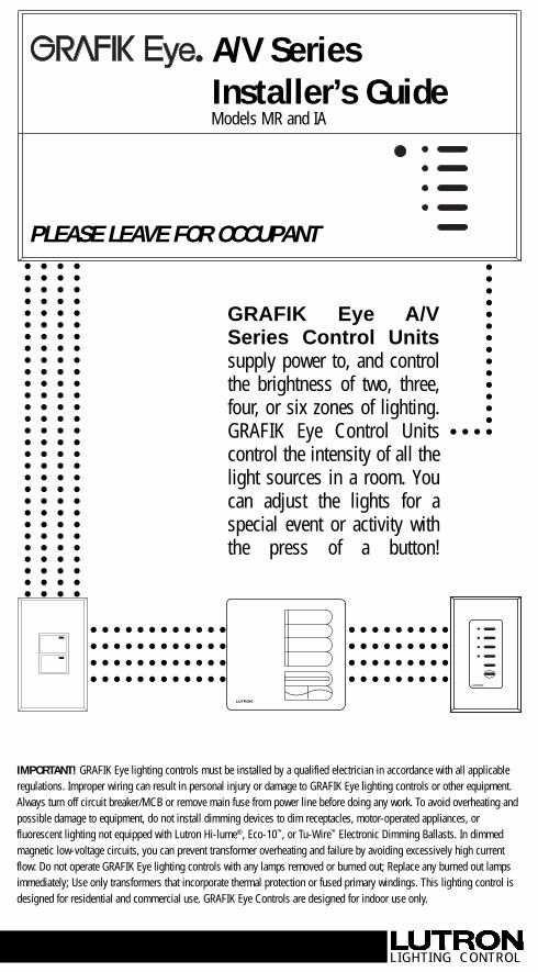
GRAFIK Eye A/V Series Control Units supply power to, and control the brightness of two, three, four, or six zones of lighting. GRAFIK Eye Control Units control the intensity of all the light sources in a room. You can adjust the lights for a special event or activity with the press of a button! ○ ○ ○ ○ ○ ○ ○ ○ ○ ○ ○ ○ ○ ○ ○ ○ ○ ○ ○ ○ ○ ○ ○ ○ ○ ○ ○ ○ ○ ○ ○ ○ ○ ○ ○ ○ ○ ○ ○ ○ ○ ○ ○ ○ ○ ○ ○ ○ ○ ○ ○ ○ ○ ○ ○ ○ ○ ○ ○ ○ ○ ○ ○ ○ ○ ○ ○ ○ ○ ○ ○ ○ ○ ○ ○ ○
Citation preview
○
○
○
○
○
○
○
○
○
○
○
○
○
○
○
○
○
○
○
○
○
○
○
○
○
○
○
○
○
○
○
○
○
○
○
○
○
○
○
○
○
○
○
○
○
○
○
○
○
○
○
○
○
○
○
○
○
○
○
○
○
○
○
○
○
○
○
○
○
○
○
○
○
○
○
○
○
○
○
○
○
○
○
○
○
○
○
○
○
○
○
○
○
○
○
○
○
○
○
○
○
○
○
○
○
○
○
○
○
○
○
○
○
○
○
○
○
○
○
○
○
○
○
○
○
○
○
○
○
○
○
○
○
○
○
○
○
○
○
○
○
○
○
○
○
○
○
○
○
○
○
○
○
○
○
○
○
○
○
○
○
○
○
○
○
○
○
○
○
GRAFIK Eye A/VSeries Control Unitssupply power to, and controlthe brightness of two, three,four, or six zones of lighting.GRAFIK Eye Control Unitscontrol the intensity of all thelight sources in a room. Youcan adjust the lights for aspecial event or activity withthe press of a button!
○ ○ ○
IMPORTANT! GRAFIK Eye lighting controls must be installed by a qualified electrician in accordance with all applicableregulations. Improper wiring can result in personal injury or damage to GRAFIK Eye lighting controls or other equipment.Always turn off circuit breaker/MCB or remove main fuse from power line before doing any work. To avoid overheating andpossible damage to equipment, do not install dimming devices to dim receptacles, motor-operated appliances, orfluorescent lighting not equipped with Lutron Hi-lume®, Eco-10™, or Tu-Wire™ Electronic Dimming Ballasts. In dimmedmagnetic low-voltage circuits, you can prevent transformer overheating and failure by avoiding excessively high currentflow: Do not operate GRAFIK Eye lighting controls with any lamps removed or burned out; Replace any burned out lampsimmediately; Use only transformers that incorporate thermal protection or fused primary windings. This lighting control isdesigned for residential and commercial use. GRAFIK Eye Controls are designed for indoor use only.
LIGHTING CONTROL
○ ○ ○ ○ ○ ○ ○ ○ ○ ○ ○ ○ ○ ○ ○ ○ ○ ○ ○ ○ ○ ○ ○ ○ ○ ○ ○ ○ ○ ○ ○ ○ ○ ○ ○ ○ ○ ○
○ ○ ○ ○ ○ ○ ○ ○ ○ ○ ○ ○ ○ ○ ○ ○ ○ ○ ○ ○ ○ ○ ○ ○ ○ ○ ○ ○ ○ ○ ○ ○ ○ ○ ○ ○ ○ ○
○ ○ ○ ○ ○ ○ ○ ○ ○ ○ ○ ○ ○ ○ ○ ○ ○ ○ ○ ○ ○ ○ ○ ○ ○ ○ ○ ○ ○ ○ ○ ○ ○ ○ ○ ○ ○ ○
○ ○ ○ ○ ○ ○ ○ ○ ○ ○ ○ ○ ○ ○ ○ ○ ○ ○ ○ ○ ○ ○ ○ ○ ○ ○ ○ ○ ○ ○ ○ ○ ○ ○ ○ ○ ○ ○
LUTRON
LUTRONPLEASE LEAVE FOR OCCUPANT
A/V SeriesInstaller’s GuideModels MR and IA

How to use this manual
Control Unit only?Follow Step 1 and Step 3
Accessory Controls too?
Do you have: Then read this . . . . . . on page:
Appendix G: Troubleshooting 18Problems?
Questions aboutClass 2/PELV wiring?
STEP 4: Setting Up System Communications 10Assigning Accessory Controls to the Control Units they should operate.
STEP 1: Installing A/V Series Control Units 3How to wire and mount GRAFIK Eye A/V Series Control Units.
STEP 2: Installing Accessory Controls 4DIP switch address settings, wiring, and mounting.
STEP 3: Setting Up Control Units 6Identifying load types and setting up lighting scenes.
Appendix A: More about Class 2/PELV Wiring 12
Appendix B: Special Mounting Considerations 14
Appendix C: Power Boosters, 14Electronic Low Voltage Interfaces,and Fluorescent Dimming Ballast Interfaces
Appendix D: GRX-TVI 0-10 Volt Ballast Interface 15
Appendix E: HP 2•4•6 Dimming Modules 17
Appendix F: Infrared Controls 18
Questions? Need technical assistance?
■ In the U.S., Canada and the Caribbean:1-800-523-9466
■ In Mexico, Central and South America:1-610-282-3800
■ In Japan: 03-5405-7333■ In Hong Kong: 2104-7733
■ In the U.K.: 0800-282-107■ In Europe: 44-171-702-0657■ All others: 1-610-282-3800■ Website address: www.lutron.com■ E-mail: [email protected]
WarrantyLutron warrants each new unit to be free from defects in materials and workmanship and to perform under normal use and service. Thiswarranty shall run only for a period of one year from the date of purchase and Lutron's obligations under this warranty are limited to remedyingany defect or replacing any defective part and shall be effective only if the defective unit is shipped to Lutron postage prepaid within 12 monthsafter purchase. Damage due to abuse, misuse, inadequate wiring or installation is not covered by this warranty. In no event shall Lutron or anyother seller be liable for any other loss or damage, including consequential or special damages that may arise through the use by a purchaseror others of this device and the purchaser assumes and will hold harmless Lutron in respect of all such loss. Although every attempt is made toensure that catalogue information is accurate and up-to-date, please check with Lutron before specifying or purchasing this equipment toconfirm availability, exact specifications and suitability for your application. This product may be covered by one or more of the following U.S.patents: 4,797,599; 4,803,380; 4,825,075; 4,893,062; 5,030,893; 5,191,265; 5,430,356; 5,463,286; 5,530,322; 5,808,417; DES 308,647; DES310,349; DES 311,170; DES 311,371; DES 311,382; DES 311,485; DES 311,678; DES 313,738; DES 335,867; DES 344,264; DES 370,663;DES 378,814 and corresponding foreign patents. U.S. and foreign patents pending. Lutron, GRAFIK Eye, and Hi-lume are registeredtrademarks; Hi-Power, Eco-10, LIAISON, Designer, Tu-Wire, and Architrave are trademarks of Lutron Electronics Co., Inc. © 1999 LutronElectronics Co., Inc.
®
Safety standards listed above apply to one or more products in the GRAFIK Eye product line. Consult factory for specific information.
LUTRON-Quality SystemsRegistered to ISO 9001
Phone Assistance . . . Worldwide!
Load Types
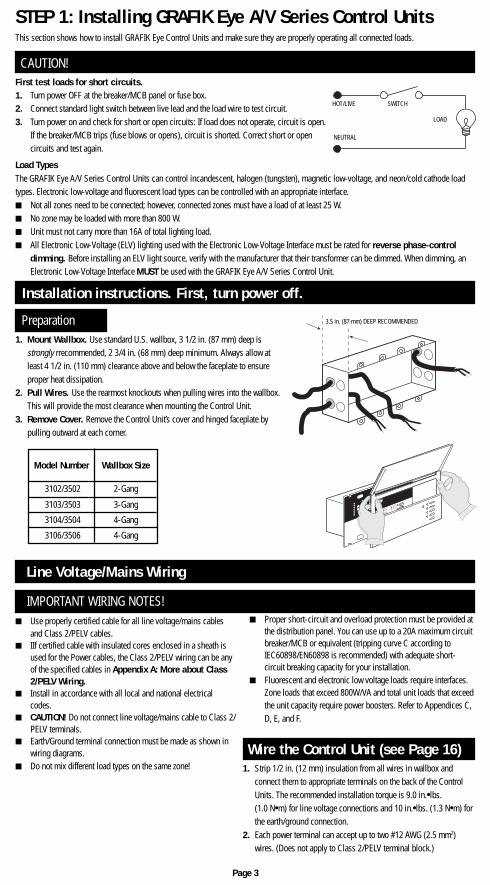
STEP 1: Installing GRAFIK Eye A/V Series Control Units
First test loads for short circuits.1. Turn power OFF at the breaker/MCB panel or fuse box.2. Connect standard light switch between live lead and the load wire to test circuit.3. Turn power on and check for short or open circuits: If load does not operate, circuit is open.
If the breaker/MCB trips (fuse blows or opens), circuit is shorted. Correct short or opencircuits and test again.
This section shows how to install GRAFIK Eye Control Units and make sure they are properly operating all connected loads.
The GRAFIK Eye A/V Series Control Units can control incandescent, halogen (tungsten), magnetic low-voltage, and neon/cold cathode loadtypes. Electronic low-voltage and fluorescent load types can be controlled with an appropriate interface.■ Not all zones need to be connected; however, connected zones must have a load of at least 25 W.■ No zone may be loaded with more than 800 W.■ Unit must not carry more than 16A of total lighting load.■ All Electronic Low-Voltage (ELV) lighting used with the Electronic Low-Voltage Interface must be rated for reverse phase-control
dimming. Before installing an ELV light source, verify with the manufacturer that their transformer can be dimmed. When dimming, anElectronic Low-Voltage Interface MUST be used with the GRAFIK Eye A/V Series Control Unit.
CAUTION!
Installation instructions. First, turn power off.
Preparation
230V˜LUTRON50/60Hz
LOAD PER ZONE: 40 - 800W
MAX UNIT LOAD: 10A, 2300WPreset Lighting Control
LIVE TERMINALS AT REAR
DO NOT WIRE LIVE
U. K. 071-702-0657
U. S. A. (610) 282-3800COOPERSBURG, PA USA 18036 GRX-3104-CE UP
Made in U.S.A.
12V
SELV OUTPUT
!
CB E 5
145-049
GRX-Z
■ Use properly certified cable for all line voltage/mains cablesand Class 2/PELV cables.
■ IIf certified cable with insulated cores enclosed in a sheath isused for the Power cables, the Class 2/PELV wiring can be anyof the specified cables in Appendix A: More about Class2/PELV Wiring.
■ Install in accordance with all local and national electricalcodes.
■ CAUTION! Do not connect line voltage/mains cable to Class 2/PELV terminals.
■ Earth/Ground terminal connection must be made as shown inwiring diagrams.
■ Do not mix different load types on the same zone!
■ Proper short-circuit and overload protection must be provided atthe distribution panel. You can use up to a 20A maximum circuitbreaker/MCB or equivalent (tripping curve C according toIEC60898/EN60898 is recommended) with adequate short-circuit breaking capacity for your installation.
■ Fluorescent and electronic low voltage loads require interfaces.Zone loads that exceed 800W/VA and total unit loads that exceedthe unit capacity require power boosters. Refer to Appendices C,D, E, and F.
Line Voltage/Mains Wiring
IMPORTANT WIRING NOTES!
Wire the Control Unit (see Page 16)
Page 3
HOT/LIVE SWITCH
LOAD
NEUTRAL
3.5 in. (87 mm) DEEP RECOMMENDED
1. Mount Wallbox. Use standard U.S. wallbox, 3 1/2 in. (87 mm) deep isstrongly rrecommended, 2 3/4 in. (68 mm) deep minimum. Always allow atleast 4 1/2 in. (110 mm) clearance above and below the faceplate to ensureproper heat dissipation.
2. Pull Wires. Use the rearmost knockouts when pulling wires into the wallbox.This will provide the most clearance when mounting the Control Unit.
3. Remove Cover. Remove the Control Unit’s cover and hinged faceplate bypulling outward at each corner.
1. Strip 1/2 in. (12 mm) insulation from all wires in wallbox andconnect them to appropriate terminals on the back of the ControlUnits. The recommended installation torque is 9.0 in.●lbs.(1.0 N●m) for line voltage connections and 10 in.●lbs. (1.3 N●m) forthe earth/ground connection.
2. Each power terminal can accept up to two #12 AWG (2.5 mm2)wires. (Does not apply to Class 2/PELV terminal block.)
Model Number Wallbox Size
3102/3502
3103/3503
3106/3506
2-Gang
3-Gang
4-Gang
4-Gang
3104/3504

1. Strip 1 in. (25 mm) of insulation from the Class 2/PELV cable.2. Strip 3/8 in. (8 mm) of insulation from each wire.3. Connect the Class2/PELV wires to the Class 2/PELV
terminal block. Make sure no bare wire is exposed aftermaking connections. The recommended installation torque is3.5 in.●lbs. (0.4 N●m) for Class 2/PELV connections.
4. The Class 2/PELV cable and terminal block should be separatedfrom line voltage/mains cables by at least 1/4 in. (7 mm).
Class 2/PELV Wiring
Use recommended cable as specified in Appendix A: More AboutClass 2/PELV Wiring.
Connect Class 2/PELV wiring only if your project has AccessoryControls and/or more than one Control Unit.
Wiring Note■ Use the rearmost knockouts when pulling wires into the wallbox.
This will provide the most clearance when mounting the ControlUnit.
Mounting
1. Mount as shown using the four screws provided. (Whenmounted in the wallbox, the Class 2/PELV cable and terminalblock should remain separated from the line voltage/mainscables.)
2. Reattach the faceplate to the Control Unit by pushing inward ateach corner.
Testing: Do the lights work?
M S
FADE TEMPORARY
MASTER
ZONES
ZONE 5 ZONE 6ZONE 3 ZONE 4ZONE 1 ZONE 2
Scene 1buttonOFF
Zone intensity raise andlower buttons
Scene 1 LED
STEP 2: Installing Accessory Controls
■ Accessory Controls must be installed by a qualified electrician.■ Accessory Controls use Class 2 or PELV wiring methods as applicable
in your locale.— Using Class 2 wiring methods: Accessory Controls must be
connected in accordance with the 1996 National Electrical Code,Article 725-54(a), (1) Exception No. 3 or the Canadian 1994 CECode Handbook, Rule 16-212, Subrule (4). Check with your localelectrical inspector to comply with local codes and wiringpractices.
■ Accessory Controls must be mounted in a wallbox. Please refer toinstruction sheet included with each Accessory Control to determinewallbox requirements.
NTGRX-2B-SL Entrance/Special Function ControlNTGRX-4S Scene Selection Control with Raise/LowerNTGRX-4S-IR Scene Selection Control/Infrared ReceiverNTGRX-4B Scene Selection ControlNTGRX-4M Master ControlNTGRX-4PS Partition ControlGRX-CIR* Infrared Ceiling ReceiverGRX-4S-DW* ArchitraveTM Door Jamb ControlGRX-AV* Interface ControlGRX-RS232* RS-232 Interface ControlGRX-PRG* Personal Computer InterfaceGRX-IT/GRX-8IT Infrared Handheld Transmitter
(see Appendix C)EGRX-4S* European Style 4S ControlEGRX-4S-IR* European Style 4S Control/Infrared
Receiver
. . . and more!
* Wires like any other Accessory Control, but has specialmounting, addressing, and/or programming requirements.
Examples of Accessory ControlsIMPORTANT WIRING NOTES!
Review Appendix A BEFORE wiring!
Page 4
1. Restore Power.2. Press Scene 1 button on front of the GRAFIK Eye Control
Unit. The Scene 1 LED will light.3. Press zone or to raise or lower the light levels. Make
sure that the Control Unit is dimming all connected loads. Referto Appendix G: Troubleshooting, or call Lutron.
1
2
3
4
LINE VOLTAGE/MAINS CABLE
CLASS 2/PELVTERMINAL
CLASS 2/PELV CABLE
1.0 in. (25 mm)
3/8 in.(9.5 mm)
LINE VOLTAGE/MAINS CABLE
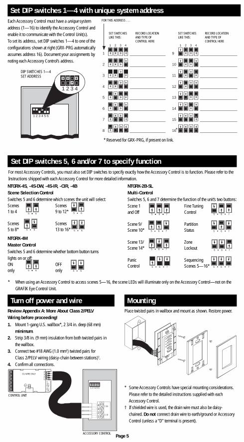
Each Accessory Control must have a unique systemaddress (1—16) to identify the Accessory Control andenable it to communicate with the Control Unit(s).To set its address, set DIP switches 1—4 to one of theconfigurations shown at right (GRX-PRG automaticallyassumes address 16). Document your assignments bynoting each Accessory Control’s address.
* Reserved for GRX-PRG, if present on link.
Set DIP switches 1—4 with unique system address
For most Accessory Controls, you must also set DIP switches to specify exactly how the Accessory Control is to function. Please refer to theInstructions shipped with each Accessory Control for more detailed information.
Set DIP switches 5, 6 and/or 7 to specify function
* When using an Accessory Control to access scenes 5—16, the scene LEDs will illuminate only on the Accessory Control—not on theGRAFIK Eye Control Unit.
Page 5
MountingTurn off power and wirePlace twisted pairs in wallbox and mount as shown. Restore power.Review Appendix A: More About Class 2/PELV
Wiring before proceeding!1. Mount 1-gang U.S. wallbox*, 2 3/4 in. deep (68 mm)
minimum.2. Strip 3/8 in. (9 mm) insulation from both twisted pairs in
the wallbox.3. Connect two #18 AWG (1.0 mm2) twisted pairs for
Class 2/PELV wiring (daisy-chain between stations)†.4. Confirm all connections.
* Some Accessory Controls have special mounting considerations.Please refer to the detailed instructions supplied with eachAccessory Control.
† If shielded wire is used, the drain wire must also be daisy-chained. Do not connect drain wire to earth/ground or AccessoryControl (unless a “D” terminal is present).Class 2/PELV
Terminal
Class 2/PELV Cable1 2 3 4 5 6
1
432
4321
CU WIRE ONLY
US
A:
Cla
ss 2
IEC
: P
ELV
CONTROL UNIT
ACCESSORY CONTROL
NTGRX-4S, -4S-DW, -4S-IR, -CIR, -4BScene Selection ControlSwitches 5 and 6 determine which scenes the unit will select:Scenes Scenes1 to 4 9 to 12*
Scenes Scenes5 to 8* 13 to 16*
NTGRX-4MMaster ControlSwitches 5 and 6 determine whether bottom button turnslights on or off:ON OFFonly only
5 6 5 6
5 6 5 6
5 6 5 6
1 2 3 4
1
2
3
4
5
6
7
8
1 2 3 4
9
10
11
12
13
14
15
16*
FOR THIS ADDRESS . . .
SET SWITCHESLIKE THIS:
RECORD LOCATIONAND TYPE OFCONTROL HERE
SET SWITCHESLIKE THIS:
RECORD LOCATIONAND TYPE OFCONTROL HERE
1 2 3 4 5 6
1 2 3 4
DIP SWITCHES 1—4SET ADDRESS
NTGRX-2B-SLMulti-ControlSwitches 5, 6 and 7 determine the function of the unit’s two buttons:Scene 1 Fine Tuningand Off Control
Scene 9/ PartitionScene 10* Status
Scene 13/ ZoneScene 14* Lockout
Panic SequencingControl Scenes 5—16*
5 6 7
5 6 7
5 6 7
5 6 7
5 6 7
5 6 7
5 6 7
5 6 7
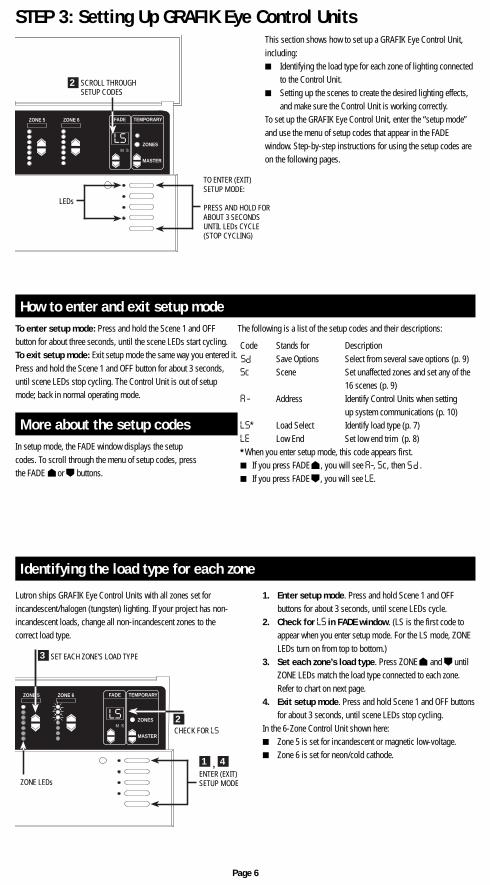
To enter setup mode: Press and hold the Scene 1 and OFFbutton for about three seconds, until the scene LEDs start cycling.To exit setup mode: Exit setup mode the same way you entered it.Press and hold the Scene 1 and OFF button for about 3 seconds,until scene LEDs stop cycling. The Control Unit is out of setupmode; back in normal operating mode.
In setup mode, the FADE window displays the setupcodes. To scroll through the menu of setup codes, pressthe FADE or buttons.
STEP 3: Setting Up GRAFIK Eye Control UnitsThis section shows how to set up a GRAFIK Eye Control Unit,including:■ Identifying the load type for each zone of lighting connected
to the Control Unit.■ Setting up the scenes to create the desired lighting effects,
and make sure the Control Unit is working correctly.To set up the GRAFIK Eye Control Unit, enter the “setup mode”and use the menu of setup codes that appear in the FADEwindow. Step-by-step instructions for using the setup codes areon the following pages.
How to enter and exit setup mode
More about the setup codes
Code Stands for DescriptionSave Options Select from several save options (p. 9)
Sc Scene Set unaffected zones and set any of the16 scenes (p. 9)
A - Address Identify Control Units when settingup system communications (p. 10)
LS* Load Select Identify load type (p. 7)LE Low End Set low end trim (p. 8)*When you enter setup mode, this code appears first.■ If you press FADE , you will see A-, Sc, then .■ If you press FADE , you will see LE.
S
P
S
P
Identifying the load type for each zone
Lutron ships GRAFIK Eye Control Units with all zones set forincandescent/halogen (tungsten) lighting. If your project has non-incandescent loads, change all non-incandescent zones to thecorrect load type.
1. Enter setup mode. Press and hold Scene 1 and OFFbuttons for about 3 seconds, until scene LEDs cycle.
2. Check for LS in FADE window. (LS is the first code toappear when you enter setup mode. For the LS mode, ZONELEDs turn on from top to bottom.)
3. Set each zone’s load type. Press ZONE and untilZONE LEDs match the load type connected to each zone.Refer to chart on next page.
4. Exit setup mode. Press and hold Scene 1 and OFF buttonsfor about 3 seconds, until scene LEDs stop cycling.
In the 6-Zone Control Unit shown here:■ Zone 5 is set for incandescent or magnetic low-voltage.■ Zone 6 is set for neon/cold cathode.
Page 6
FADE TEMPORARY
MASTER
ZONES
ZONE 5 ZONE 6
M S
LS
3
2
1 4,
SET EACH ZONE’S LOAD TYPE
CHECK FOR LS
ENTER (EXIT)SETUP MODEZONE LEDs
FADE TEMPORARY
MASTER
ZONES
ZONE 5 ZONE 6
M S
LS
2 SCROLL THROUGHSETUP CODES
TO ENTER (EXIT)SETUP MODE:
PRESS AND HOLD FORABOUT 3 SECONDSUNTIL LEDs CYCLE(STOP CYCLING)
LEDs
The following is a list of the setup codes and their descriptions:
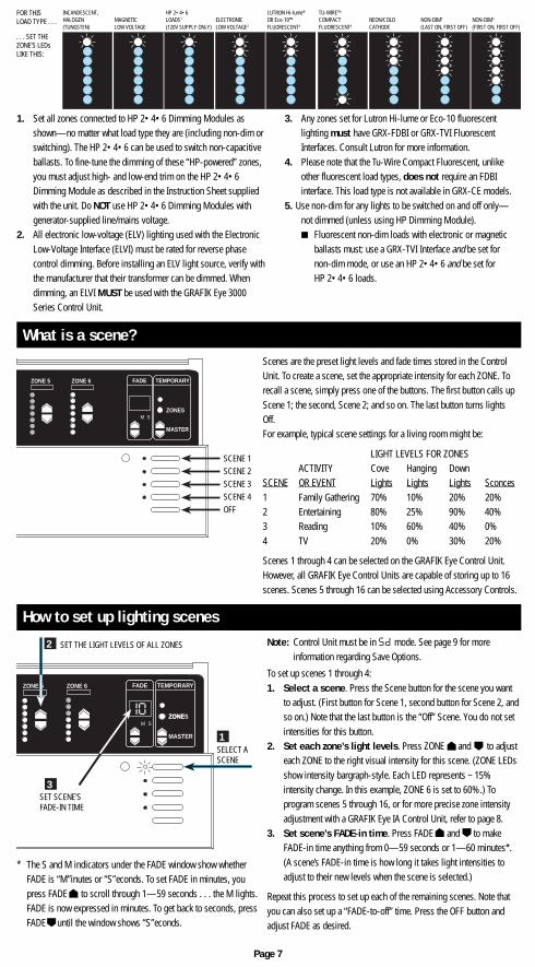
1. Set all zones connected to HP 2•4•6 Dimming Modules asshown—no matter what load type they are (including non-dim orswitching). The HP 2•4•6 can be used to switch non-capacitiveballasts. To fine-tune the dimming of these “HP-powered” zones,you must adjust high- and low-end trim on the HP 2•4•6Dimming Module as described in the Instruction Sheet suppliedwith the unit. Do NOT use HP 2•4•6 Dimming Modules withgenerator-supplied line/mains voltage.
2. All electronic low-voltage (ELV) lighting used with the ElectronicLow-Voltage Interface (ELVI) must be rated for reverse phasecontrol dimming. Before installing an ELV light source, verify withthe manufacturer that their transformer can be dimmed. Whendimming, an ELVI MUST be used with the GRAFIK Eye 3000Series Control Unit.
3. Any zones set for Lutron Hi-lume or Eco-10 fluorescentlighting must have GRX-FDBI or GRX-TVI FluorescentInterfaces. Consult Lutron for more information.
4. Please note that the Tu-Wire Compact Fluorescent, unlikeother fluorescent load types, does not require an FDBIinterface. This load type is not available in GRX-CE models.
5. Use non-dim for any lights to be switched on and off only—not dimmed (unless using HP Dimming Module).■ Fluorescent non-dim loads with electronic or magnetic
ballasts must: use a GRX-TVI Interface and be set fornon-dim mode, or use an HP 2•4•6 and be set forHP 2•4•6 loads.
What is a scene?Scenes are the preset light levels and fade times stored in the ControlUnit. To create a scene, set the appropriate intensity for each ZONE. Torecall a scene, simply press one of the buttons. The first button calls upScene 1; the second, Scene 2; and so on. The last button turns lightsOff.For example, typical scene settings for a living room might be:
LIGHT LEVELS FOR ZONESACTIVITY Cove Hanging Down
SCENE OR EVENT Lights Lights Lights Sconces1 Family Gathering 70% 10% 20% 20%2 Entertaining 80% 25% 90% 40%3 Reading 10% 60% 40% 0%4 TV 20% 0% 30% 20%
Scenes 1 through 4 can be selected on the GRAFIK Eye Control Unit.However, all GRAFIK Eye Control Units are capable of storing up to 16scenes. Scenes 5 through 16 can be selected using Accessory Controls.
Note: Control Unit must be in mode. See page 9 for moreinformation regarding Save Options.
To set up scenes 1 through 4:1. Select a scene. Press the Scene button for the scene you want
to adjust. (First button for Scene 1, second button for Scene 2, andso on.) Note that the last button is the “Off” Scene. You do not setintensities for this button.
2. Set each zone’s light levels. Press ZONE and to adjusteach ZONE to the right visual intensity for this scene. (ZONE LEDsshow intensity bargraph-style. Each LED represents ~ 15%intensity change. In this example, ZONE 6 is set to 60%.) Toprogram scenes 5 through 16, or for more precise zone intensityadjustment with a GRAFIK Eye IA Control Unit, refer to page 8.
3. Set scene’s FADE-in time. Press FADE and to makeFADE-in time anything from 0—59 seconds or 1—60 minutes*.(A scene’s FADE-in time is how long it takes light intensities toadjust to their new levels when the scene is selected.)
Repeat this process to set up each of the remaining scenes. Note thatyou can also set up a “FADE-to-off” time. Press the OFF button andadjust FADE as desired.
How to set up lighting scenes
* The S and M indicators under the FADE window show whetherFADE is “M”inutes or “S”econds. To set FADE in minutes, youpress FADE to scroll through 1—59 seconds . . . the M lights.FADE is now expressed in minutes. To get back to seconds, pressFADE until the window shows “S”econds.
S
P
Page 7
FOR THISLOAD TYPE . . .
. . . SET THEZONE’S LEDsLIKE THIS:
INCANDESCENT,HALOGEN(TUNGSTEN)
MAGNETICLOW VOLTAGE
HP 2•4•6LOADS1
(120V SUPPLY ONLY)ELECTRONICLOW VOLTAGE2
LUTRON Hi-lume®
OR Eco-10™FLUORESCENT3
TU-WIRE™COMPACTFLUORESCENT4
NEON/COLDCATHODE
NON-DIM5
(LAST ON, FIRST OFF)NON-DIM5
(FIRST ON, FIRST OFF)
FADE TEMPORARY
MASTER
ZONES
ZONE 5 ZONE 6
M S
SCENE 1SCENE 2SCENE 3SCENE 4OFF
FADE TEMPORARY
MASTER
ZONES
ZONE 5 ZONE 6
ZONEM S
1
3
2 SET THE LIGHT LEVELS OF ALL ZONES
SELECT ASCENE
SET SCENE’SFADE-IN TIME
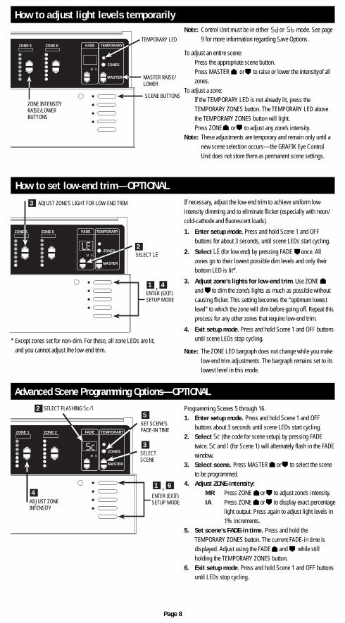
How to adjust light levels temporarily
To adjust an entire scene:Press the appropriate scene button.Press MASTER or to raise or lower the intensityof allzones.
To adjust a zone:If the TEMPORARY LED is not already lit, press theTEMPORARY ZONES button. The TEMPORARY LED abovethe TEMPORARY ZONES button will light.Press ZONE or to adjust any zone’s intensity.
Note: These adjustments are temporary and remain only until anew scene selection occurs—the GRAFIK Eye ControlUnit does not store them as permanent scene settings.
Note: Control Unit must be in either or mode. See page9 for more information regarding Save Options.
SP
S
P
If necessary, adjust the low-end trim to achieve uniform low-intensity dimming and to eliminate flicker (especially with neon/cold-cathode and fluorescent loads).
1. Enter setup mode. Press and hold Scene 1 and OFFbuttons for about 3 seconds, until scene LEDs start cycling.
2. Select LE (for low end) by pressing FADE once. Allzones go to their lowest possible dim levels and only theirbottom LED is lit*.
3. Adjust zone’s lights for low-end trim. Use ZONEand to dim the zone’s lights as much as possible withoutcausing flicker. This setting becomes the “optimum lowestlevel” to which the zone will dim before going off. Repeat thisprocess for any other zones that require low-end trim.
4. Exit setup mode. Press and hold Scene 1 and OFF buttonsuntil scene LEDs stop cycling.
Note: The ZONE LED bargraph does not change while you makelow-end trim adjustments. The bargraph remains set to itslowest level in this mode.
How to set low-end trim—OPTIONAL
* Except zones set for non-dim. For these, all zone LEDs are lit,and you cannot adjust the low-end trim.
Programming Scenes 5 through 16.1. Enter setup mode. Press and hold Scene 1 and OFF
buttons about 3 seconds until scene LEDs start cycling.2. Select Sc (the code for scene setup) by pressing FADE
twice. Sc and I (for Scene 1) will alternately flash in the FADEwindow.
3. Select scene. Press MASTER or to select the sceneto be programmed.
4. Adjust ZONE-intensity:MR Press ZONE or to adjust zone’s intensity.IA Press ZONE or to display exact percentage
light output. Press again to adjust light levels in1% increments.
5. Set scene’s FADE-in time. Press and hold theTEMPORARY ZONES button. The current FADE-in time isdisplayed. Adjust using the FADE and while stillholding the TEMPORARY ZONES button.
6. Exit setup mode. Press and hold Scene 1 and OFF buttonsuntil LEDs stop cycling.
Advanced Scene Programming Options—OPTIONAL
Page 8
FADE TEMPORARY
MASTER
ZONES
ZONE 5 ZONE 6
M S
LE
3
2
1 4,
ADJUST ZONE’S LIGHT FOR LOW-END TRIM
SELECT LE
ENTER (EXIT)SETUP MODE
FADE TEMPORARY
MASTER
ZONES
ZONE 5 ZONE 6
M S
TEMPORARY LED
MASTER RAISE/LOWER
SCENE BUTTONSZONE INTENSITYRAISE/LOWERBUTTONS
ZONE 1 ZONE 2
M S
Sc
2
3
41
FADE TEMPORARY
MASTER
ZONES
5
6,
SELECT FLASHING Sc/I
SET SCENE’SFADE-IN TIME
SELECTSCENE
ENTER (EXIT)SETUP MODEADJUST ZONE
INTENSITY
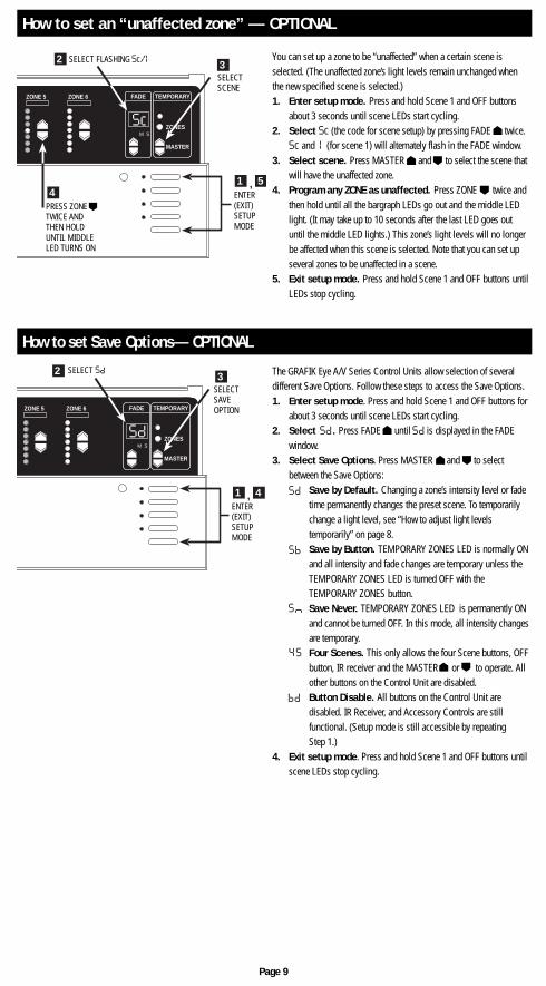
How to set an “unaffected zone” — OPTIONAL
How to set Save Options— OPTIONAL
Page 9
FADE TEMPORARY
MASTER
ZONES
ZONE 5 ZONE 6
M S
2 3
1 4,ENTER(EXIT)SETUPMODE
SELECTSAVEOPTION
SELECT S
p
FADE TEMPORARY
MASTER
ZONES
ZONE 5 ZONE 6
M S
Sc
2 3
41 5,
SELECTSCENE
ENTER(EXIT)SETUPMODE
SELECT FLASHING Sc/I
PRESS ZONETWICE ANDTHEN HOLDUNTIL MIDDLELED TURNS ON
You can set up a zone to be “unaffected” when a certain scene isselected. (The unaffected zone’s light levels remain unchanged whenthe new specified scene is selected.)1. Enter setup mode. Press and hold Scene 1 and OFF buttons
about 3 seconds until scene LEDs start cycling.2. Select Sc (the code for scene setup) by pressing FADE twice.
Sc and I (for scene 1) will alternately flash in the FADE window.3. Select scene. Press MASTER and to select the scene that
will have the unaffected zone.4. Program any ZONE as unaffected. Press ZONE twice and
then hold until all the bargraph LEDs go out and the middle LEDlight. (It may take up to 10 seconds after the last LED goes outuntil the middle LED lights.) This zone’s light levels will no longerbe affected when this scene is selected. Note that you can set upseveral zones to be unaffected in a scene.
5. Exit setup mode. Press and hold Scene 1 and OFF buttons untilLEDs stop cycling.
The GRAFIK Eye A/V Series Control Units allow selection of severaldifferent Save Options. Follow these steps to access the Save Options.1. Enter setup mode. Press and hold Scene 1 and OFF buttons for
about 3 seconds until scene LEDs start cycling.2. Select . Press FADE until is displayed in the FADE
window.3. Select Save Options. Press MASTER and to select
between the Save Options:Save by Default. Changing a zone’s intensity level or fadetime permanently changes the preset scene. To temporarilychange a light level, see “How to adjust light levelstemporarily” on page 8.Save by Button. TEMPORARY ZONES LED is normally ONand all intensity and fade changes are temporary unless theTEMPORARY ZONES LED is turned OFF with theTEMPORARY ZONES button.Save Never. TEMPORARY ZONES LED is permanently ONand cannot be turned OFF. In this mode, all intensity changesare temporary.
4 S Four Scenes. This only allows the four Scene buttons, OFFbutton, IR receiver and the MASTER or to operate. Allother buttons on the Control Unit are disabled.Button Disable. All buttons on the Control Unit aredisabled. IR Receiver, and Accessory Controls are stillfunctional. (Setup mode is still accessible by repeatingStep 1.)
4. Exit setup mode. Press and hold Scene 1 and OFF buttons untilscene LEDs stop cycling.
SP
S
P
S
P
SP
S c
P P
STEP 4: Setting Up System CommunicationsThis section shows how to set up communications betweenAccessory Controls and the Control Units they should operate.
■ You have more than one Control Unit or . . .■ You have Accessory Controls other than the
NTGRX-4S, -4B, -4S-IR, -4S-DW, or EGRX-4S, -4S-IR.
Why do you set up communications?
■ You have only one Control Unit and . . .— you have up to three of the following Accessory Controls:
NTGRX-4S, -4B, -4S-IR, -4S-DW, orEGRX-4S, -4S-IR, in any combination.
Close this manual and relax — your project will work as specifiedwithout any further wiring or setup! This diagram shows how Accessory Controls “talk” to Control
Units in a typical residential project:■ The NTGRX-2B-SL in the hallway turns lights on and off in
the master bedroom and great room. To do this, the-2B-SL “talks” to the Control Units in both of these rooms.
■ The NTGRX-4S Scene Selection Control in the masterbedroom allows you to choose four different lightingscenes. To do this, the -4S “talks” to the master bedroom’sControl Unit (but not to the Great Room’s Control Unit).
Do not set up communications if . . .
Do set up communications if . . .
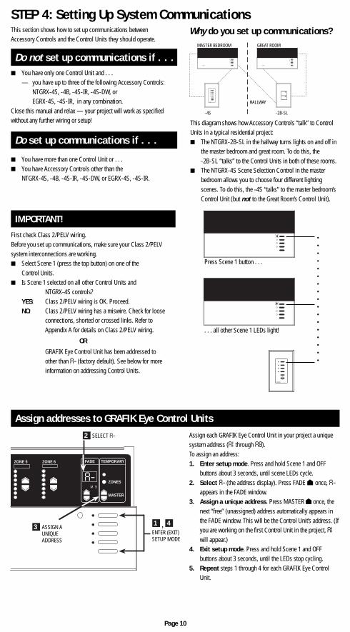
Assign addresses to GRAFIK Eye Control Units
Press Scene 1 button . . .
. . . all other Scene 1 LEDs light!
IMPORTANT!
First check Class 2/PELV wiring.Before you set up communications, make sure your Class 2/PELVsystem interconnections are working.■ Select Scene 1 (press the top button) on one of the
Control Units.■ Is Scene 1 selected on all other Control Units and
NTGRX-4S controls?YES: Class 2/PELV wiring is OK. Proceed.NO: Class 2/PELV wiring has a miswire. Check for loose
connections, shorted or crossed links. Refer toAppendix A for details on Class 2/PELV wiring.
OR
GRAFIK Eye Control Unit has been addressed toother than A- (factory default). See below for moreinformation on addressing Control Units.
Assign each GRAFIK Eye Control Unit in your project a uniquesystem address (AI through A8).To assign an address:1. Enter setup mode. Press and hold Scene 1 and OFF
buttons about 3 seconds, until scene LEDs cycle.2. Select A- (the address display). Press FADE once, A-
appears in the FADE window.3. Assign a unique address. Press MASTER once, the
next “free” (unassigned) address automatically appears inthe FADE window. This will be the Control Unit’s address. (Ifyou are working on the first Control Unit in the project, AIwill appear.)
4. Exit setup mode. Press and hold Scene 1 and OFFbuttons about 3 seconds, until the LEDs stop cycling.
5. Repeat steps 1 through 4 for each GRAFIK Eye ControlUnit.
Page 10
FADE TEMPORARY
MASTER
ZONES
ZONE 5 ZONE 6
M S
A-
2
3 1 4,
SELECT A-
ASSIGN AUNIQUEADDRESS
ENTER (EXIT)SETUP MODE
LUTRON LUTRON
LUTRON
MASTER BEDROOM GREAT ROOM
HALLWAY
-4S -2B-SL
LUTRON
○
○
○
○
○
○
○
○
○
○
○
○
○
○
○
○
○
Page 11
In order for Accessory Controls to communicate with a Control Unit, each Accessory Control must be individually configured to “talk.”
How to set up an Accessory Control to “talk” to a “listening” Control Unit.
The communication link is now established. The Control Unit will “listen” when the user presses a button on the Accessory Control. You canproceed to the next Accessory Control and set up its communications.
For more specific, step-by-step instructions about setting up communications for each type of GRAFIK Eye Accessory Control, please refer tothe instructions included with each Accessory Control.
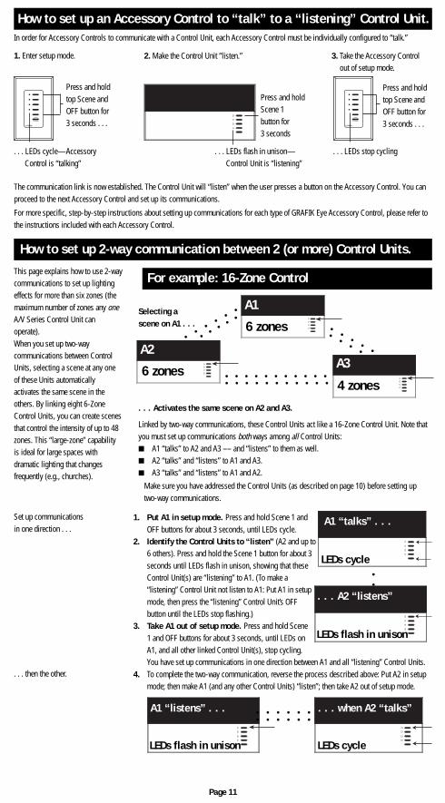
Selecting ascene on A1 . . .
. . . Activates the same scene on A2 and A3.
Linked by two-way communications, these Control Units act like a 16-Zone Control Unit. Note thatyou must set up communications both ways among all Control Units:■ A1 “talks” to A2 and A3 –– and “listens” to them as well.■ A2 “talks” and “listens” to A1 and A3.■ A3 “talks” and “listens” to A1 and A2.
Make sure you have addressed the Control Units (as described on page 10) before setting uptwo-way communications.
For example: 16-Zone Control
How to set up 2-way communication between 2 (or more) Control Units.This page explains how to use 2-waycommunications to set up lightingeffects for more than six zones (themaximum number of zones any oneA/V Series Control Unit canoperate).When you set up two-waycommunications between ControlUnits, selecting a scene at any oneof these Units automaticallyactivates the same scene in theothers. By linking eight 6-ZoneControl Units, you can create scenesthat control the intensity of up to 48zones. This “large-zone” capabilityis ideal for large spaces withdramatic lighting that changesfrequently (e.g., churches).
1. Put A1 in setup mode. Press and hold Scene 1 andOFF buttons for about 3 seconds, until LEDs cycle.
2. Identify the Control Units to “listen” (A2 and up to6 others). Press and hold the Scene 1 button for about 3seconds until LEDs flash in unison, showing that theseControl Unit(s) are “listening” to A1. (To make a“listening” Control Unit not listen to A1: Put A1 in setupmode, then press the “listening” Control Unit’s OFFbutton until the LEDs stop flashing.)
3. Take A1 out of setup mode. Press and hold Scene1 and OFF buttons for about 3 seconds, until LEDs onA1, and all other linked Control Unit(s), stop cycling.You have set up communications in one direction between A1 and all “listening” Control Units.
4. To complete the two-way communication, reverse the process described above: Put A2 in setupmode; then make A1 (and any other Control Units) “listen”; then take A2 out of setup mode.
Set up communicationsin one direction . . .
. . . then the other.
1. Enter setup mode. 2. Make the Control Unit “listen.” 3. Take the Accessory Controlout of setup mode.
Press and holdtop Scene andOFF button for3 seconds . . .
. . . LEDs cycle—AccessoryControl is “talking”
LUTRON
Press and holdScene 1button for3 seconds
. . . LEDs flash in unison—Control Unit is “listening”
Press and holdtop Scene andOFF button for3 seconds . . .
. . . LEDs stop cycling
LUTRON
○
○
○
○
○
○
○
○
○
○ ○ ○ ○ ○ ○ ○ ○ ○ ○ ○
○ ○ ○ ○ ○ ○ ○ ○ ○ ○ ○
○
○
○
○
○
○
○
○
○
○
○
A3
4 zones6 zones
6 zones
A2
A1
○
○
○
○
○
○
○ ○ ○ ○ ○ ○
○ ○ ○ ○ ○ ○
A1 “listens” . . . . . . when A2 “talks”
LEDs flash in unison LEDs cycle
A1 “talks” . . .
LEDs cycle
. . . A2 “listens”
LEDs flash in unison
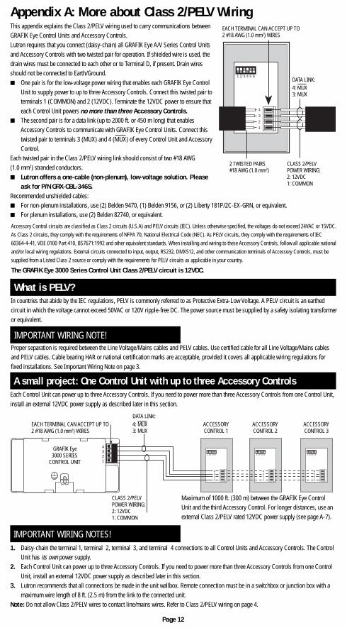
Appendix A: More about Class 2/PELV WiringThis appendix explains the Class 2/PELV wiring used to carry communications betweenGRAFIK Eye Control Units and Accessory Controls.Lutron requires that you connect (daisy-chain) all GRAFIK Eye A/V Series Control Unitsand Accessory Controls with two twisted pair for operation. If shielded wire is used, thedrain wires must be connected to each other or to Terminal D, if present. Drain wiresshould not be connected to Earth/Ground.■ One pair is for the low-voltage power wiring that enables each GRAFIK Eye Control
Unit to supply power to up to three Accessory Controls. Connect this twisted pair toterminals 1 (COMMON) and 2 (12VDC). Terminate the 12VDC power to ensure thateach Control Unit powers no more than three Accessory Controls.
■ The second pair is for a data link (up to 2000 ft. or 450 m long) that enablesAccessory Controls to communicate with GRAFIK Eye Control Units. Connect thistwisted pair to terminals 3 (MUX) and 4 (MUX) of every Control Unit and AccessoryControl.
Each twisted pair in the Class 2/PELV wiring link should consist of two #18 AWG(1.0 mm2) stranded conductors.■ Lutron offers a one-cable (non-plenum), low-voltage solution. Please
ask for P/N GRX-CBL-346S.Recommended unshielded cables:■ For non-plenum installations, use (2) Belden 9470, (1) Belden 9156, or (2) Liberty 181P/2C-EX-GRN, or equivalent.■ For plenum installations, use (2) Belden 82740, or equivalent.
Each Control Unit can power up to three Accessory Controls. If you need to power more than three Accessory Controls from one Control Unit,install an external 12VDC power supply as described later in this section.
A small project: One Control Unit with up to three Accessory Controls
IMPORTANT WIRING NOTE!Proper separation is required between the Line Voltage/Mains cables and PELV cables. Use certified cable for all Line Voltage/Mains cablesand PELV cables. Cable bearing HAR or national certification marks are acceptable, provided it covers all applicable wiring regulations forfixed installations. See Important Wiring Note on page 3.
In countries that abide by the IEC regulations, PELV is commonly referred to as Protective Extra-Low Voltage. A PELV circuit is an earthedcircuit in which the voltage cannot exceed 50VAC or 120V ripple-free DC. The power source must be supplied by a safety isolating transformeror equivalent.
What is PELV?
IMPORTANT WIRING NOTES!1. Daisy-chain the terminal 1, terminal 2, terminal 3, and terminal 4 connections to all Control Units and Accessory Controls. The Control
Unit has its own power supply.2. Each Control Unit can power up to three Accessory Controls. If you need to power more than three Accessory Controls from one Control
Unit, install an external 12VDC power supply as described later in this section.3. Lutron recommends that all connections be made in the unit wallbox. Remote connection must be in a switchbox or junction box with a
maximum wire length of 8 ft. (2.5 m) from the link to the connected unit.Note: Do not allow Class 2/PELV wires to contact line/mains wires. Refer to Class 2/PELV wiring on page 4.
Page 12
1 2 3 4 5 6
4
3
2
1
EACH TERMINAL CAN ACCEPT UP TO2 #18 AWG (1.0 mm2) WIRES
CLASS 2/PELVPOWER WIRING:2: 12VDC1: COMMON
2 TWISTED PAIRS#18 AWG (1.0 mm2)
DATA LINK:4: MUX3: MUX
Maximum of 1000 ft. (300 m) between the GRAFIK Eye ControlUnit and the third Accessory Control. For longer distances, use anexternal Class 2/PELV rated 12VDC power supply (see page A-7).
EACH TERMINAL CAN ACCEPT UP TO2 #18 AWG (1.0 mm2) WIRES
CLASS 2/PELVPOWER WIRING:2: 12VDC1: COMMON
ACCESSORYCONTROL 1
ACCESSORYCONTROL 2
ACCESSORYCONTROL 3
GRAFIK Eye3000 SERIES
CONTROL UNIT1 2 3 4 5 6
4321
1 2 3 4 5 6
4321
1 2 3 4 5 6
4321
4321
DATA LINK:4: MUX3: MUX
Accessory Control circuits are classified as Class 2 circuits (U.S.A) and PELV circuits (IEC). Unless otherwise specified, the voltages do not exceed 24VAC or 15VDC.As Class 2 circuits, they comply with the requirements of NFPA 70, National Electrical Code (NEC). As PELV circuits, they comply with the requirements of IEC60364-4-41, VDE 0100 Part 410, BS7671:1992 and other equivalent standards. When installing and wiring to these Accessory Controls, follow all applicable nationaland/or local wiring regulations. External circuits connected to input, output, RS232, DMX512, and other communication terminals of Accessory Controls, must besupplied from a Listed Class 2 source or comply with the requirements for PELV circuits as applicable in your country.
The GRAFIK Eye 3000 Series Control Unit Class 2/PELV circuit is 12VDC.
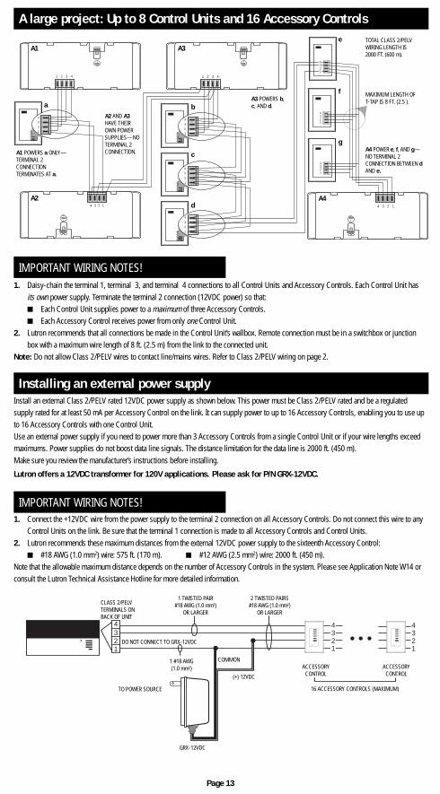
A large project: Up to 8 Control Units and 16 Accessory Controls
IMPORTANT WIRING NOTES!1. Daisy-chain the terminal 1, terminal 3, and terminal 4 connections to all Control Units and Accessory Controls. Each Control Unit has
its own power supply. Terminate the terminal 2 connection (12VDC power) so that:■ Each Control Unit supplies power to a maximum of three Accessory Controls.■ Each Accessory Control receives power from only one Control Unit.
2. Lutron recommends that all connections be made in the Control Unit’s wallbox. Remote connection must be in a switchbox or junctionbox with a maximum wire length of 8 ft. (2.5 m) from the link to the connected unit.
Note: Do not allow Class 2/PELV wires to contact line/mains wires. Refer to Class 2/PELV wiring on page 2.
Install an external Class 2/PELV rated 12VDC power supply as shown below. This power must be Class 2/PELV rated and be a regulatedsupply rated for at least 50 mA per Accessory Control on the link. It can supply power to up to 16 Accessory Controls, enabling you to use upto 16 Accessory Controls with one Control Unit.Use an external power supply if you need to power more than 3 Accessory Controls from a single Control Unit or if your wire lengths exceedmaximums. Power supplies do not boost data line signals. The distance limitation for the data line is 2000 ft. (450 m).Make sure you review the manufacturer’s instructions before installing.
Lutron offers a 12VDC transformer for 120V applications. Please ask for P/N GRX-12VDC.
Installing an external power supply
IMPORTANT WIRING NOTES!1. Connect the +12VDC wire from the power supply to the terminal 2 connection on all Accessory Controls. Do not connect this wire to any
Control Units on the link. Be sure that the terminal 1 connection is made to all Accessory Controls and Control Units.2. Lutron recommends these maximum distances from the external 12VDC power supply to the sixteenth Accessory Control:
■ #18 AWG (1.0 mm2) wire: 575 ft. (170 m). ■ #12 AWG (2.5 mm2) wire: 2000 ft. (450 m).Note that the allowable maximum distance depends on the number of Accessory Controls in the system. Please see Application Note W14 orconsult the Lutron Technical Assistance Hotline for more detailed information.
Page 13
4321
4321
4 3 2 1
1 2 3 41 2 3 4
4 3 2 1
4
3
2
1
4
3
2
14
3
2
1
4
3
2
1
4
3
2
1
4
3
2
1
4
3
2
1
4321
4
3
2
1
A1
A2
A3
A1 POWERS a ONLY—TERMINAL 2CONNECTIONTERMINATES AT a.
A2 AND A3HAVE THEIROWN POWERSUPPLIES—NOTERMINAL 2CONNECTION.
b
c
d
e
f
g
A4
A3 POWERS b,c, AND d.
TOTAL CLASS 2/PELVWIRING LENGTH IS2000 FT. (600 m).
MAXIMUM LENGTH OFT-TAP IS 8 FT. (2.5 ).
A4 POWER e, f, AND g—NO TERMINAL 2CONNECTION BETWEEN dAND e.
a
321
4 4321
4321
LUTRONLUTRON
CLASS 2/PELVTERMINALS ONBACK OF UNIT
1 TWISTED PAIR#18 AWG (1.0 mm2)
OR LARGER
2 TWISTED PAIRS#18 AWG (1.0 mm2)
OR LARGER
ACCESSORYCONTROL
ACCESSORYCONTROL
16 ACCESSORY CONTROLS (MAXIMUM)
COMMON
(+) 12VDC
1 #18 AWG(1.0 mm2)
TO POWER SOURCE
DO NOT CONNECT TO GRX-12VDC
GRX-12VDC
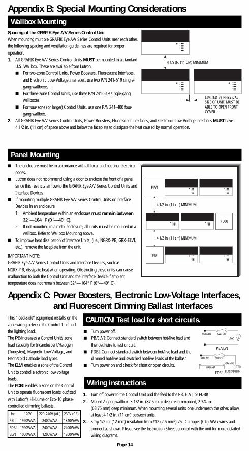
Spacing of the GRAFIK Eye A/V Series Control UnitWhen mounting multiple GRAFIK Eye A/V Series Control Units near each other,the following spacing and ventilation guidelines are required for properoperation.1. All GRAFIK Eye A/V Series Control Units MUST be mounted in a standard
U.S. Wallbox. These are available from Lutron:■ For two-zone Control Units, Power Boosters, Fluorescent Interfaces,
and Electronic Low-Voltage Interfaces, use two P/N 241-519 single-gang wallboxes.
■ For three-zone Control Units, use three P/N 241-519 single-gangwallboxes.
■ For four-zone (or larger) Control Units, use one P/N 241-400 four-gang wallbox.
2. All GRAFIK Eye A/V Series Control Units, Power Boosters, Fluorescent Interfaces, and Electronic Low-Voltage Interfaces MUST have4 1/2 in. (11 cm) of space above and below the faceplate to dissipate the heat caused by normal operation.
Appendix B: Special Mounting ConsiderationsWallbox Mounting
■ The enclosure must be in accordance with all local and national electricalcodes.
■ Lutron does not recommend using a door to enclose the front of a panel,since this restricts airflow to the GRAFIK Eye A/V Series Control Units andInterface Devices.
■ If mounting multiple GRAFIK Eye A/V Series Control Units or InterfaceDevices in an enclosure:1. Ambient temperature within an enclosure must remain between
32°—104° F (0°—40° C).2. If not mounting in a metal enclosure, all units must be mounted in a
wallbox. Refer to Wallbox Mounting above.■ To improve heat dissipation of Interface Units, (i.e., NGRX-PB, GRX-ELVI,
etc.), remove the faceplate from the unit.
IMPORTANT NOTE:GRAFIK Eye A/V Series Control Units and Interface Devices, such asNGRX-PB, dissipate heat when operating. Obstructing these units can causemalfunction to both the Control Unit and the Interface Device if ambienttemperature does not remain between 32°—104° F (0°—40° C).
Panel Mounting
Appendix C: Power Boosters, Electronic Low-Voltage Interfaces,and Fluorescent Dimming Ballast Interfaces
■ Turn power off.■ PB/ELVI: Connect standard switch between hot/live lead and
the load wire to test circuit.■ FDBI: Connect standard switch between hot/live lead and the
dimmed hot/live and switched hot/live leads of the ballast.■ Turn power on and check for short or open circuits.
Wiring instructions
CAUTION! Test load for short circuits.This “load-side” equipment installs on thezone wiring between the Control Unit andthe lighting load.The PB increases a Control Unit’s zoneload capacity for Incandescent/Halogen(Tungsten), Magnetic Low Voltage, andNeon/cold Cathode load types.The ELVI enables a zone of the ControlUnit to control electronic low-voltageloads.The FDBI enables a zone on the ControlUnit to operate fluorescent loads outfittedwith Lutron’s Hi-Lume or Eco-10 phase-controlled dimming ballasts.
1. Turn off power to the Control Unit and the feed to the PB, ELVI, or FDBI!2. Mount 2-gang wallbox: 3 1/2 in. (87.5 mm) deep recommended, 2 3/4 in.
(68.75 mm) deep minimum. When mounting several units one underneath the other, allowat least 4 1/2 in. (11 cm) between units.
3. Strip 1/2 in. (12 mm) insulation from #12 (2.5 mm2) 75 °C copper (CU) AWG wires andconnect as shown. Please see the Instruction Sheet supplied with the unit for more detailedwiring diagrams.
Page 14
4 1/2 IN. (11 CM) MINIMUM
LIMITED BY PHYSICALSIZE OF UNIT. MUST BEABLE TO OPEN FRONTCOVER.
PB/ELVI
HOT/LIVE SWITCH
LOAD
FDBI
HOT/LIVE SWITCH
ORANGE
BLACK/BROWNBALLAST
ELVI
FDBI
PB
4 1/2 in. (11 cm) MINIMUM
4 1/2 in. (11 cm) MINIMUM
Unit 120V 220-240V (AU) 230V (CE)
PB 1920W/VA 2400W/VA 1840W/VA
FDBI 1920W/VA 2400W/VA 2400W/VA
ELVI 1000W/VA 1200W/VA 1200W/VA
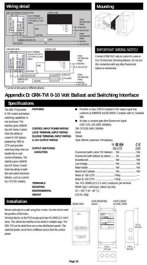
Wiring detail
* Can be on the same or different phases.
Connect ZONE OUT only to Lutron Hi-Lume orEco-10 Electronic Dimming Ballasts. Do not usethis connection with any other fluorescentballast or transformer.
IMPORTANT WIRING NOTES!
Mounting
Mount vertically on a wall using four screws. Use the unit to markthe position of the holes.Terminal blocks on the PCB accept up to two #12 AWG (2.5 mm2)wires. This allows the interface to be wired in multiple ways. TheGRX-TVI can be wired from one or two distribution panels. Theswitched power can be from a different source than the controlpower.
Installation
Page 15
Appendix D: GRX-TVI 0-10 Volt Ballast and Switching Interface
The GRX-TVI provides0-10V control and ballastswitching capabilities inone enclosure. Theinterface gives GRAFIKEye A/V Series ControlUnits the ability tocontrol 0-10V ballastspowered by 100V to277V and providesswitching relays that canhandle the in-rushcurrent of ballasts. Theinterface gives GRAFIKEye A/V Series ControlUnits the ability to bothdim and switch electronicballasts, such as Lutron’sEco-10 (TVE models).
FEATURES ■ Provides a Class 2/PELV isolated 0-10V output signal thatconforms to EN60929 and IEC60929. Complies with UL Standard508.
■ Accepts a constant-gate drive fluorescent signal.(100-127V, 220-240V, 50/60Hz).
CONTROL INPUT POWER RATING 100-127/220-240V, 50/60HzL2/H2 TERMINAL INPUT RATING 20mADL2/DH2 TERMINAL INPUT RATING 100mA0-10V OUTPUT RATING 10µA-300mA (maximum 150 ballasts)
OUTPUT SWITCHING 100-277V 230VCAPACITIES Fluorescent (with Lutron TVE ballasts) .. 16A ......................... 10A
Fluorescent (with ballasts by others) ...... 5A .......................... 5AXIncandescent .......................................... 16A ......................... 10ALow Voltage ........................................... 16A ......................... 10AMetal Halide .......................................... 16A ......................... 10ANeon/Cold Cathode ............................... 16A ......................... 10AMotor @ 100-127V .............................. 1/4Hp ........................ —Motor @ 220-277V .............................. 1/2Hp ........................ —
TERMINALS Two #12-20AWG (0.5-2.5 mm2) conductors per terminal.MOUNTING NEMA Type 1 enclosure, indoor use only.ENVIRONMENTAL 32—104 ˚F (0—40 ˚C).WEIGHT 4.25 lb. (2kg)
Specifications
®
100-120V
220-240V
N2 DH2 H1 N1 N1 SH1 + –
Max 0.3A0-10V
Control Inputs Load SwitchedH2
100-277V
GROUNDCONNECTIONS
PCBCOOPERSBURG, PA 18036 U.S.A.G 2 CB144-317 Rev. 1.9
0-10V INTERFACE CONTROLControl Input:
100-120V, 220-240V 50/60HzSwitched Output: 100-277
GRX-TVI
Incandescent 16A
Fluorescent 5A
Magnetic Low-voltage 16A
Electronic Low-voltage 16A
Neon/Cold Cathode 16A
Motor 1/4 HP@120V1/2 HP@277V
®
ControlGRX-TVI Input Rating
IH2 0.02AIDH2 0.1A
Load Type Switched
Ratings ®
10A
5AX
10A
10A
10A
ControlGRX-TVI Input Rating
IH2 0.02AIDH2 0.1A
Load Type Switched
Ratings ✔ ACN
003 715 277
0-10V Output Rating
Max. 0.3A PELV
0-10V Output Rating
Max. 0.3A Class 2
Switched µ
INSIDE VIEWFOUR MOUNTINGHOLES
FOUR SCREWSSECURE COVER
3.30 in.(84 mm)
6.10 in.(155 mm)
12.5 in.(318 mm)
EACH TERMINALCAN ACCEPT UP TO2 #12 AWG (2.5 mm2)WIRES
FROMDISTRIBUTIONPANEL:NEUTRAL
HOT/LIVE IN*
FROMDISTRIBUTIONPANEL:NEUTRALHOT/LIVE IN*
CONTROL UNIT
ZONE
NEUTRAL
HOT/LIVE IN
LOAD
NGRX-PB OR NGRX-ELVI (REAR VIEW)
DIMMED HOT/LIVE OUT
NEUT
RAL
N
DO N
OT U
SEHO
T/LI
VE ~
ZONE
OUT
~ZO
NE IN
FROMDISTRIBUTIONPANEL:NEUTRAL
HOT/LIVE IN*
FROMDISTRIBUTIONPANEL:
HOT/LIVE IN*
EACH TERMINALCAN ACCEPT UP TO2 #12 AWG (2.5 mm2)WIRES
CONTROL UNIT
ZONE
NEUTRAL
NEUTRAL
Hi-Lume OR Eco-10 BALLAST
TO LAMPS
FDBI (REAR VIEW)
NEUTRAL
SWITCHED HOT/LIVE
DIMMED HOT/LIVE OUT
NEUT
RAL
N
SW H
OTHO
T/LI
VE ~
ZONE
OUT
~ZO
NE IN
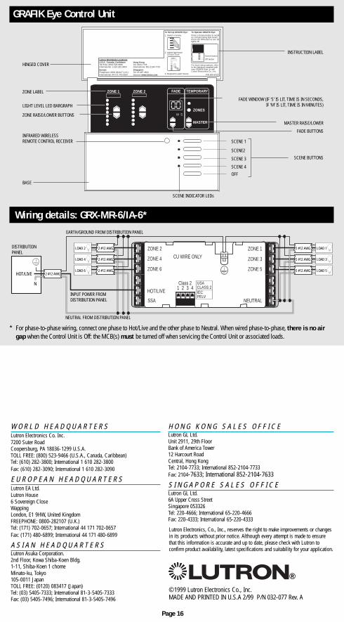
* For phase-to-phase wiring, connect one phase to Hot/Live and the other phase to Neutral. When wired phase-to-phase, there is no airgap when the Control Unit is Off: the MCB(s) must be turned off when servicing the Control Unit or associated loads.
GRAFIK Eye Control Unit
W O R L D H E A D Q U A R T E R SLutron Electronics Co. Inc.7200 Suter RoadCoopersburg, PA 18036-1299 U.S.A.TOLL FREE: (800) 523-9466 (U.S.A., Canada, Caribbean)Tel: (610) 282-3800; International 1 610 282-3800Fax: (610) 282-3090; International 1 610 282-3090
E U R O P E A N H E A D Q U A R T E R SLutron EA Ltd.Lutron House6 Sovereign CloseWappingLondon, E1 9HW, United KingdomFREEPHONE: 0800-282107 (U.K.)Tel: (171) 702-0657; International 44 171 702-0657Fax: (171) 480-6899; International 44 171 480-6899
A S I A N H E A D Q U A R T E R SLutron Asuka Corporation.2nd Floor, Kowa Shiba-Koen Bldg.1-11, Shiba-Koen 1 chomeMinato-ku, Tokyo105-0011 JapanTOLL FREE: (0120) 083417 (Japan)Tel: (03) 5405-7333; International 81-3-5405-7333Fax: (03) 5405-7496; International 81-3-5405-7496
H O N G K O N G S A L E S O F F I C ELutron GL Ltd.Unit 2911, 29th FloorBank of America Tower12 Harcourt RoadCentral, Hong KongTel: 2104-7733; International 852-2104-7733Fax: 2104-7633; International 852-2104-7633
S I N G A P O R E S A L E S O F F I C ELutron GL Ltd.6A Upper Cross StreetSingapore 053326Tel: 220-4666; International 65-220-4666Fax: 220-4333; International 65-220-4333
Lutron Electronics, Co., Inc., reserves the right to make improvements or changesin its products without prior notice. Although every attempt is made to ensurethat this information is accurate and up to date, please check with Lutron toconfirm product availability, latest specifications and suitability for your application.
Wiring details: GRX-MR-6/IA-6*
©1999 Lutron Electronics Co., Inc.MADE AND PRINTED IN U.S.A 2/99 P/N 032-077 Rev. A
®
Page 16
ZONE 4
ZONE 6
HOT/LIVE
SSA
CU WIRE ONLY
ZONE 2
Class 21 2 3 4
ZONE 3
ZONE 5
NEUTRAL
ZONE 1
USACLASS 2IECPELV
HOT/LIVE
N
LOAD 2
LOAD 4
LOAD 6
LOAD 1
LOAD 3
LOAD 5
DISTRIBUTIONPANEL
NEUTRAL FROM DISTRIBUTION PANEL
INPUT POWER FROMDISTRIBUTION PANEL
EARTH/GROUND FROM DISTRIBUTION PANEL
2 #12 AWG2 #12 AWG
2 #12 AWG
2 #12 AWG
2 #12 AWG
2 #12 AWG
2 #12 AWG
FADE TEMPORARY
MASTER
ZONES
ZONE 1 ZONE 2
M S
00
To Set Up GRAFIK Eye:
1. Select a Scene.
2. Adjust light level of each Zone.
3. Repeat for each Scene.
To Operate GRAFIK Eye:Press a Scene button to recallits corresponding light levels.Press the Off button to turn alllights off.
For more setup options, referto the literature supplied withyour GRAFIK Eye, or callLutron Electronics Co., Inc.
P/N 500-8723
U.S.A., Canada, CaribbeanToll Free: (800) 523-9466International: 1-610-282-3800EuropeFreephone: 0800 282107 (U.K.)International: 44-171-702-0657
Hong KongTel: 2104-7733International: 852-2104-7733SingaporeTel: 65 487 2820
Lutron W orldwide LocationsZONE 1
Internet: www.lutron.com
Scene button
Off button
HINGED COVER
ZONE LABEL
LIGHT LEVEL LED BARGRAPH
ZONE RAISE/LOWER BUTTONS
INFRARED WIRELESSREMOTE CONTROL RECEIVER
BASE
INSTRUCTION LABEL
FADE WINDOW (IF ‘S’ IS LIT, TIME IS IN SECONDS,IF ‘M’ IS LIT, TIME IS IN MINUTES)
MASTER RAISE/LOWER
FADE BUTTONS
SCENE BUTTONS
SCENE 1
SCENE2
SCENE 3
SCENE 4
OFF
SCENE INDICATOR LEDs
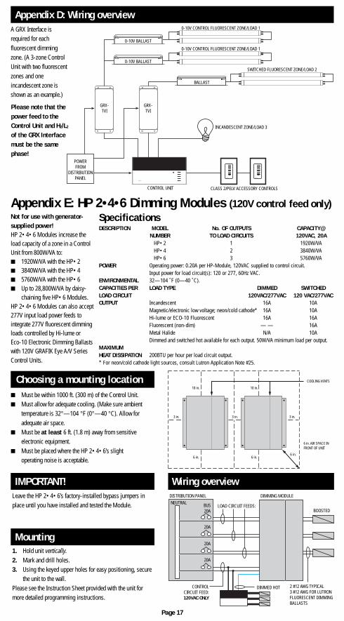
Appendix E: HP 2•4•6 Dimming Modules (120V control feed only)
Leave the HP 2•4•6’s factory-installed bypass jumpers inplace until you have installed and tested the Module.
1. Hold unit vertically.2. Mark and drill holes.3. Using the keyed upper holes for easy positioning, secure
the unit to the wall.Please see the Instruction Sheet provided with the unit formore detailed programming instructions.
Mounting
IMPORTANT!
Not for use with generator-supplied power!HP 2•4•6 Modules increase theload capacity of a zone in a ControlUnit from 800W/VA to:■ 1920W/VA with the HP•2■ 3840W/VA with the HP•4■ 5760W/VA with the HP•6■ Up to 28,800W/VA by daisy-
chaining five HP•6 Modules.HP 2•4•6 Modules can also accept277V input load power feeds tointegrate 277V fluorescent dimmingloads controlled by Hi-lume orEco-10 Electronic Dimming Ballastswith 120V GRAFIK Eye A/V SeriesControl Units.
DESCRIPTION MODEL No. OF OUTPUTS CAPACITY@NUMBER TO LOAD CIRCUITS 120VAC, 20A
HP•2 1 1920W/VAHP•4 2 3840W/VAHP•6 3 5760W/VA
POWER Operating power: 0.20A per HP-Module, 120VAC supplied to control circuit.Input power for load circuit(s): 120 or 277, 60Hz VAC.
ENVIRONMENTAL 32—104 ˚F (0—40 ˚C).CAPACITIES PER LOAD TYPE DIMMED SWITCHEDLOAD CIRCUIT 120VAC/277VAC 120 VAC/277VACOUTPUT Incandescent 16A 10A
Magnetic/electronic low voltage; neon/cold cathode* 16A 10AHi-lume or ECO-10 Fluorescent 16A 16AFluorescent (non-dim) — — 16AMetal Halide N/A 10ADimmed and switched hot available for each output. 50W/VA minimum load per output.
MAXIMUMHEAT DISSIPATION 200BTU per hour per load circuit output.* For neon/cold cathode light sources, consult Lutron Application Note #25.
Specifications
Choosing a mounting location■ Must be within 1000 ft. (300 m) of the Control Unit.■ Must allow for adequate cooling. (Make sure ambient
temperature is 32°—104 °F (0°—40 °C). Allow foradequate air space.
■ Must be at least 6 ft. (1.8 m) away from sensitiveelectronic equipment.
■ Must be placed where the HP 2•4•6’s slightoperating noise is acceptable.
Appendix D: Wiring overviewA GRX Interface isrequired for eachfluorescent dimmingzone. (A 3-zone ControlUnit with two fluorescentzones and oneincandescent zone isshown as an example.)
Page 17
Wiring overview
Please note that thepower feed to theControl Unit and H2/L2
of the GRX Interfacemust be the samephase!
LUTRON LUTRON
LUTRON
0-10V CONTROL FLUORESCENT ZONE/LOAD 1
0-10V CONTROL FLUORESCENT ZONE/LOAD 1
0-10V BALLAST
POWERFROM
DISTRIBUTIONPANEL
GRX-TVI
GRX-TVI
BALLAST
SWITCHED FLUORESCENT ZONE/LOAD 2
INCANDESCENT ZONE/LOAD 3
CONTROL UNIT CLASS 2/PELV ACCESSORY CONTROLS
0-10V BALLAST
COOLING VENTS
6 in. AIR SPACE INFRONT OF UNIT
10 in.10 in.
3 in. 3 in.
6 in. 6 in.
3 in.
6 in.
DISTRIBUTION PANEL
2 #12 AWG TYPICAL3 #12 AWG FOR LUTRONFLUORESCENT DIMMINGBALLASTS
DIMMING MODULE
LOAD CIRCUIT FEEDS:
CONTROLCIRCUIT FEED:120VAC ONLY
DIMMED HOT
NEUTRAL BUS20A
20A
20A
20A
BOOSTED
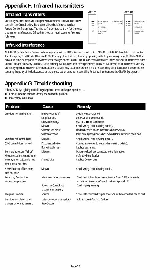
Appendix G: TroubleshootingIf the GRAFIK Eye lighting controls in your project aren’t working as specified . . .■ Consult the chart below to identify and correct the problem.■ If necessary, call Lutron.
A ZONE control affects morethan one zone
Accessory Control doesnot function properly
Faceplate is warm
Unit does not allow scenechanges or zone adjustments
Unit may be set to an optionalSave Option.
Normal Solid-state controls dissipate about 2% of the connected load as heat.
Miswire or loose connection Check and tighten loose connections at Class 2/PELV terminalson Unit and Accessory Controls (refer to Appendix A).
Accessory Control not Confirm programming.programmed properly
Miswire Check wiring (refer to wiring detail).
ZONE control does not work Disconnected wires Connect zone wires to loads (refer to wiring details).Burned-out lamps Replace bad lamps.Miswire Make sure loads are connected to the right zones
(refer to wiring details).Shorted triac Replace Control Unit.
Unit does not control load Miswire Check wiring (refer to wiring details).
1 or more zones are “full-on”when any scene is on and zoneintensity is not adjustable (andzone is not a non-dim)
Unit does not turn lights on Breaker/MCB is off Switch breaker/MCB on.Long fade time Set FADE time to 0 seconds.Low zone settings Use zone for each scene.Miswire Check wiring (refer to wiring details).System short circuit Find and correct shorts in fixtures and/or wallbox.System overload Make sure lighting loads don’t exceed Unit’s maximum rated load.
Problem Cause Remedy
Refer to page 9 for Save Options.
Appendix F: Infrared Transmitters
GRAFIK Eye Control Units are equipped with an Infrared Receiver. This allowscontrol of the Control Unit with the optional Handheld Infrared WirelessRemote Control Transmitters. The Infrared Transmitters control 4 (or 8) scenesplus master raise/lower and Off. With this you can recall scenes or fine-tunelight levels.
Infrared Transmitters
Infrared Interference
Page 18
GRX-8ITGRX-IT
LUTRON R LUTRON R
SCENE BUTTONS(1—4)
SCENE BUTTONS(5—8)
OFF BUTTON
MASTER RAISE/LOWER
SCENE BUTTONS(1—4)
OFF BUTTON
MASTER RAISE/LOWER
All GRAFIK Eye A/V Series Control Units are equipped with an IR Receiver for use with Lutron GRX-IT and GRX-8IT handheld remote controls.The IR frequency for all Control Units is 40.000 KHz. Any other device continuously operating in the frequency range from 30 KHz to 50 KHzmay cause either no response or unwanted scene changes on the Control Unit. Fluorescent ballasts are a known cause of IR interference to theControl Unit and Accessory Controls. Lutron dimming ballasts have been thoroughly tested to ensure that there is no IR interference with anyGRAFIK Eye product. However, other manufacturer's ballasts may cause interference. It is the responsibility of the contractor to determine theoperating frequency of the ballasts used on the project. Lutron takes no responsibility for ballast interference to the GRAFIK Eye system.