Embed Size (px)
Citation preview

Water Conditioning Control System
Installation, Operation and Maintenance Manual
Autotrol Performa Valve Series® ™
2
Table of Contents
Special Valve Features. . . . . . . . . . . . . . . . . . . 3
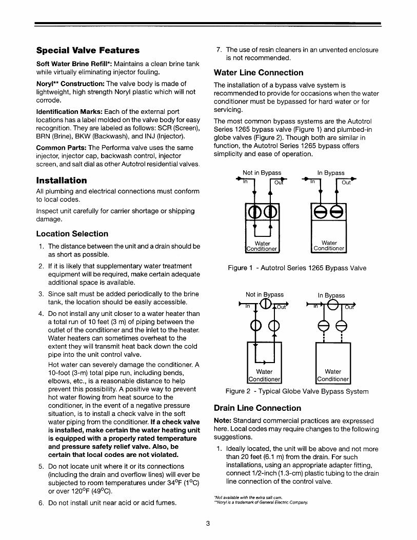
Installation . . . . . . . . . . . . . . . . . . . . . . . . . . . . 3Location SelectionWater Line ConnectionDrain Line ConnectionBrine LineOverflow Line Connection
Placing Conditioner into Operation . . . . . . . . . 5Electrical Connection
400 Series Control Settings. . . . . . . . . . . . . . . 6440i
Programming460i
ProgrammingTime of Day SettingHardness SettingCapacity SettingCalendar Override Setting
Common Features . . . . . . . . . . . . . . . . . . . . . . 7Salt Dial AdjustmentGuest CycleManual Regeneration
900 ProSeries Control Settings . . . . . . . . . . . . 9940 ProSet
ProgrammingAdjustment of Brine ControlManual Regeneration
960 ProSoftProgrammingLevel I FeaturesLevel II FeaturesManual RegenerationAutomatic Regeneration
Removing the Valve Assembly for Servicing . 15
Removing 440i or 460i for Servicing . . . . . . . 16
Preventive Maintenance. . . . . . . . . . . . . . . . . 16Brine TankInjector Screw and InjectorWater Meter
Specifications. . . . . . . . . . . . . . . . . . . . . . . . . 18
Pressure Graphs. . . . . . . . . . . . . . . . . . . . . . . 19
Identification of Control Valving . . . . . . . . . . . 20
Valve Disc Principle of Operation . . . . . . . . . . 20
Flow Diagrams . . . . . . . . . . . . . . . . . . . . . . . . 20
Replacement Parts. . . . . . . . . . . . . . . . . . . . . 22
Troubleshooting . . . . . . . . . . . . . . . . . . . . . . . 25
Disinfection of Water Conditioners . . . . . . . . 30

5
Placing Conditioner into OperationAfter all previous steps have been completed, the unit is ready to be placed into operation. Follow these steps carefully.
1. Remove control valve cover by first releasing the plastic clip from the back of the cover. Pull back of cover slightly outward and lift up.
Note: The following steps will require turning the indicator knob (Figures 5, 6, 11, and 13) to various positions. Manually rotate the camshaft COUNTERCLOCKWISE only until indicator knob points to desired position. (See manual regeneration sections for each control’s manual operation.)
2. Rotate indicator knob COUNTERCLOCKWISE until it points directly to the word BACKWASH.
3. Fill media tank with water.
A. With water supply off, place the bypass valve(s) into the “service” position.
B. Open water supply valve very slowly to approximately the 1/4 open position.
IMPORTANT: If opened too rapidly or too far, media may be lost. In the 1/4 open position, you should hear air escaping slowly from the drain line.
C. When all of the air has been purged from the tank (water begins to flow steadily from the drain), open the main supply valve all the way.
D. Allow water to run to drain until clear.E. Turn off water supply and let the unit stand for
about five minutes. This will allow all trapped air to escape from the tank.
4. Add water to brine tank (initial fill).
With a bucket or hose, add approximately 4 gallons (15 liters) of water to brine tank. If the tank has a salt platform above the bottom of the tank, add water until the level is approximately
1 inch (25 mm) above the platform.
5. Place the conditioner into operation.
A. With the water supply valve completely open, carefully advance the indicator knob COUNTERCLOCKWISE to the center of the BRINE REFILL position. Hold at this position until water starts to flow through the brine line into the brine tank. Do not run for more than one or two minutes.
B. Advance the indicator knob COUNTERCLOCKWISE until it points to the center of the BRINE/SLOW RINSE position.
C. With the conditioner in this position, check to see if water is being drawn from the brine tank. The water level in the brine tank will recede very slowly. Observe water level for at least three minutes. If the water level does not recede, or if it goes up, reference the Troubleshooting section.
D. Advance the indicator knob COUNTERCLOCKWISE to the SERVICE position and run water from a nearby faucet until the water is clear and soft.
Electrical Connection100 VAC, 115 VAC, and 230 VAC units: Remove twist tie from the power cord and extend cord to its full length. Make sure power source matches the rating printed on the control. Be certain a wall switch does not control the outlet.
12 VAC: Connect the plug of the transformer (supplied) secondary cable to the mating socket at the rear or bottom of the timer housing. Be certain the transformer is secure and is plugged into a power source of correct voltage that is not controlled by a wall switch.

8
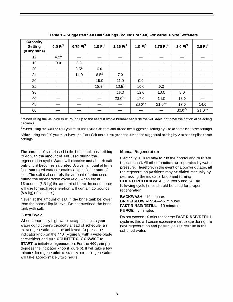
1 When using the 940 you must round up to the nearest whole number because the 940 does not have the option of selecting decimals.2 When using the 440i or 460i you must use Extra Salt cam and divide the suggested setting by 2 to accomplish these settings.
*When using the 940 you must have the Extra Salt main drive gear and divide the suggested setting by 2 to accomplish these settings.
The amount of salt placed in the brine tank has nothing to do with the amount of salt used during the regeneration cycle. Water will dissolve and absorb salt only until it becomes saturated. A given amount of brine (salt-saturated water) contains a specific amount of salt. The salt dial controls the amount of brine used during the regeneration cycle (e.g., when set at 15 pounds (6.8 kg) the amount of brine the conditioner will use for each regeneration will contain 15 pounds (6.8 kg) of salt, etc.)
Never let the amount of salt in the brine tank be lower than the normal liquid level. Do not overload the brine tank with salt.
Guest Cycle
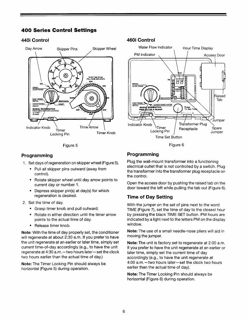
When abnormally high water usage exhausts your water conditioner’s capacity ahead of schedule, an extra regeneration can be achieved. Depress the indicator knob on the 440i (Figure 5) with a wide-blade screwdriver and turn COUNTERCLOCKWISE to START to initiate a regeneration. For the 460i, simply depress the indicator knob (Figure 6). It will take a few minutes for regeneration to start. A normal regeneration will take approximately two hours.
Manual Regeneration
Electricity is used only to run the control and to rotate the camshaft. All other functions are operated by water pressure. Therefore, in the event of a power outage, all the regeneration positions may be dialed manually by depressing the indicator knob and turning COUNTERCLOCKWISE (Figures 5 and 6). The following cycle times should be used for proper regeneration:
BACKWASH—14 minutesBRINE/SLOW RINSE—52 minutes FAST RINSE/REFILL—10 minutesPURGE—6 minutes
Do not exceed 10 minutes for the FAST RINSE/REFILL cycle as this will cause excessive salt usage during the next regeneration and possibly a salt residue in the softened water.
Table 1 – Suggested Salt Dial Settings (Pounds of Salt) For Various Size Softeners
Capacity Setting
(Kilograins)0.5 Ft3 0.75 Ft3 1.0 Ft3 1.25 Ft3 1.5 Ft3 1.75 Ft3 2.0 Ft3 2.5 Ft3
12 4.51 — — — — — — —
16 9.0 5.5 — — — — — —
20 — 8.51 6.0 — — — —
24 — 14.0 8.51 7.0 — — — —
30 — — 15.0 11.0 9.0 — — —
32 — — 18.51 12.51 10.0 9.0 — —
35 — — — 16.0 12.0 10.0 9.0 —
40 — — — 23.02* 17.0 14.0 12.0 —
48 — — — — 28.02* 21.02* 17.0 14.0
60 — — — — — — 30.02* 21.02*
9
900 ProSeries Control Settings
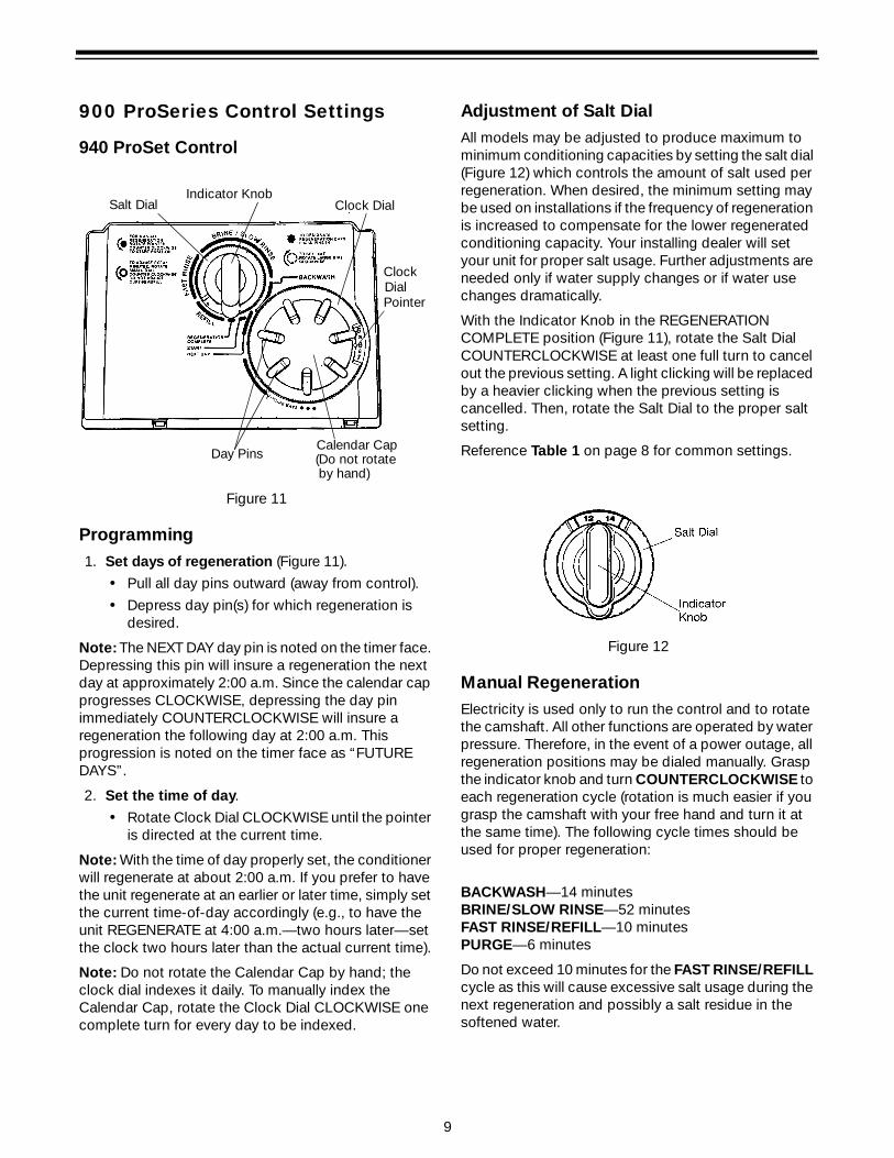
940 ProSet Control
Figure 11
Programming1. Set days of regeneration (Figure 11).
• Pull all day pins outward (away from control).
• Depress day pin(s) for which regeneration is desired.
Note: The NEXT DAY day pin is noted on the timer face. Depressing this pin will insure a regeneration the next day at approximately 2:00 a.m. Since the calendar cap progresses CLOCKWISE, depressing the day pin immediately COUNTERCLOCKWISE will insure a regeneration the following day at 2:00 a.m. This progression is noted on the timer face as “FUTURE DAYS”.
2. Set the time of day.
• Rotate Clock Dial CLOCKWISE until the pointer is directed at the current time.
Note: With the time of day properly set, the conditioner will regenerate at about 2:00 a.m. If you prefer to have the unit regenerate at an earlier or later time, simply set the current time-of-day accordingly (e.g., to have the unit REGENERATE at 4:00 a.m.—two hours later—set the clock two hours later than the actual current time).
Note: Do not rotate the Calendar Cap by hand; the clock dial indexes it daily. To manually index the Calendar Cap, rotate the Clock Dial CLOCKWISE one complete turn for every day to be indexed.
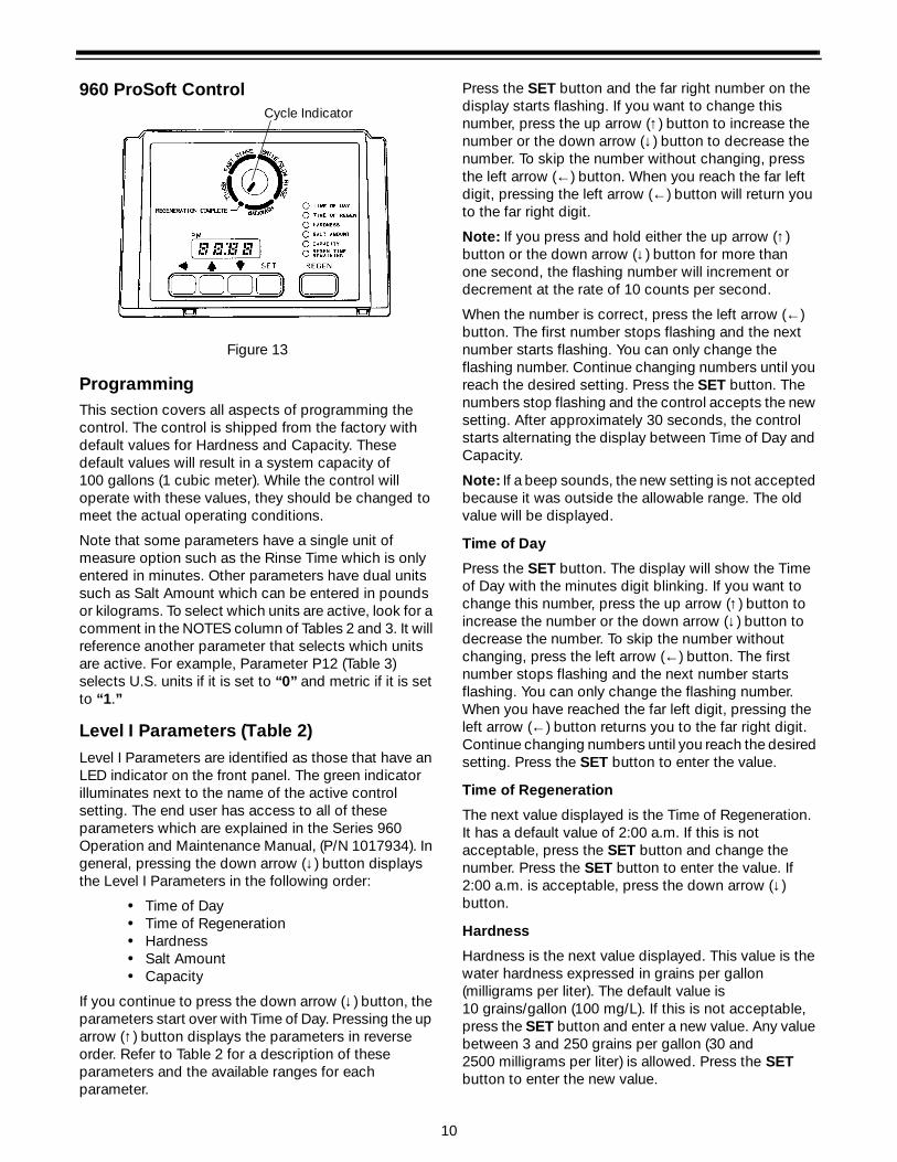
Adjustment of Salt DialAll models may be adjusted to produce maximum to minimum conditioning capacities by setting the salt dial (Figure 12) which controls the amount of salt used per regeneration. When desired, the minimum setting may be used on installations if the frequency of regeneration is increased to compensate for the lower regenerated conditioning capacity. Your installing dealer will set your unit for proper salt usage. Further adjustments are needed only if water supply changes or if water use changes dramatically.
With the Indicator Knob in the REGENERATION COMPLETE position (Figure 11), rotate the Salt Dial COUNTERCLOCKWISE at least one full turn to cancel out the previous setting. A light clicking will be replaced by a heavier clicking when the previous setting is cancelled. Then, rotate the Salt Dial to the proper salt setting.
Reference Table 1 on page 8 for common settings.
Figure 12
Manual RegenerationElectricity is used only to run the control and to rotate the camshaft. All other functions are operated by water pressure. Therefore, in the event of a power outage, all regeneration positions may be dialed manually. Grasp the indicator knob and turn COUNTERCLOCKWISE to each regeneration cycle (rotation is much easier if you grasp the camshaft with your free hand and turn it at the same time). The following cycle times should be used for proper regeneration:
BACKWASH—14 minutesBRINE/SLOW RINSE—52 minutes FAST RINSE/REFILL—10 minutesPURGE—6 minutes
Do not exceed 10 minutes for the FAST RINSE/REFILL cycle as this will cause excessive salt usage during the next regeneration and possibly a salt residue in the softened water.
Salt DialIndicator Knob
Clock
Day Pins (Do not rotate Calendar Cap
Dial
by hand)
Pointer
Clock Dial
10
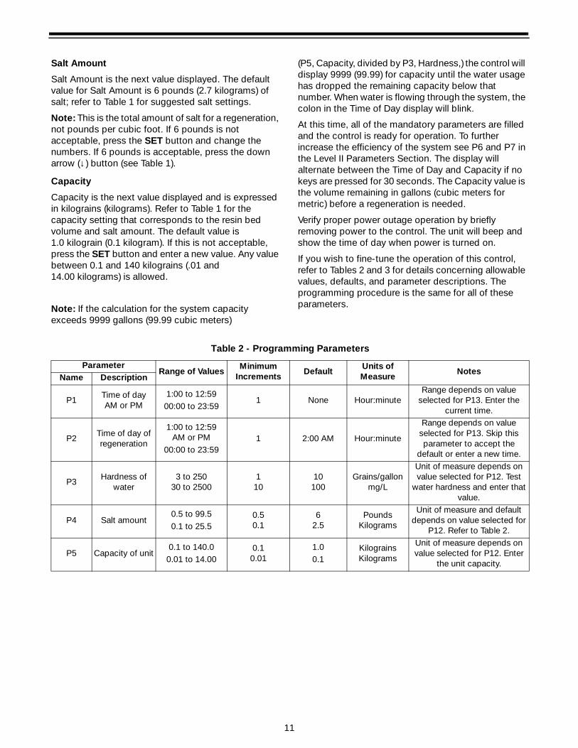
960 ProSoft Control
Figure 13
ProgrammingThis section covers all aspects of programming the control. The control is shipped from the factory with default values for Hardness and Capacity. These default values will result in a system capacity of 100 gallons (1 cubic meter). While the control will operate with these values, they should be changed to meet the actual operating conditions.
Note that some parameters have a single unit of measure option such as the Rinse Time which is only entered in minutes. Other parameters have dual units such as Salt Amount which can be entered in pounds or kilograms. To select which units are active, look for a comment in the NOTES column of Tables 2 and 3. It will reference another parameter that selects which units are active. For example, Parameter P12 (Table 3) selects U.S. units if it is set to “0” and metric if it is set to “1.”
Level I Parameters (Table 2)Level I Parameters are identified as those that have an LED indicator on the front panel. The green indicator illuminates next to the name of the active control setting. The end user has access to all of these parameters which are explained in the Series 960 Operation and Maintenance Manual, (P/N 1017934). In general, pressing the down arrow (↓) button displays the Level I Parameters in the following order:
• Time of Day• Time of Regeneration• Hardness• Salt Amount • Capacity
If you continue to press the down arrow (↓) button, the parameters start over with Time of Day. Pressing the up arrow (↑) button displays the parameters in reverse order. Refer to Table 2 for a description of these parameters and the available ranges for each parameter.
Press the SET button and the far right number on the display starts flashing. If you want to change this number, press the up arrow (↑) button to increase the number or the down arrow (↓) button to decrease the number. To skip the number without changing, press the left arrow (←) button. When you reach the far left digit, pressing the left arrow (←) button will return you to the far right digit.
Note: If you press and hold either the up arrow (↑) button or the down arrow (↓) button for more than one second, the flashing number will increment or decrement at the rate of 10 counts per second.
When the number is correct, press the left arrow (←) button. The first number stops flashing and the next number starts flashing. You can only change the flashing number. Continue changing numbers until you reach the desired setting. Press the SET button. The numbers stop flashing and the control accepts the new setting. After approximately 30 seconds, the control starts alternating the display between Time of Day and Capacity.
Note: If a beep sounds, the new setting is not accepted because it was outside the allowable range. The old value will be displayed.
Time of Day
Press the SET button. The display will show the Time of Day with the minutes digit blinking. If you want to change this number, press the up arrow (↑) button to increase the number or the down arrow (↓) button to decrease the number. To skip the number without changing, press the left arrow (←) button. The first number stops flashing and the next number starts flashing. You can only change the flashing number. When you have reached the far left digit, pressing the left arrow (←) button returns you to the far right digit. Continue changing numbers until you reach the desired setting. Press the SET button to enter the value.
Time of Regeneration
The next value displayed is the Time of Regeneration. It has a default value of 2:00 a.m. If this is not acceptable, press the SET button and change the number. Press the SET button to enter the value. If 2:00 a.m. is acceptable, press the down arrow (↓) button.
Hardness
Hardness is the next value displayed. This value is the water hardness expressed in grains per gallon (milligrams per liter). The default value is 10 grains/gallon (100 mg/L). If this is not acceptable, press the SET button and enter a new value. Any value between 3 and 250 grains per gallon (30 and2500 milligrams per liter) is allowed. Press the SET button to enter the new value.
Cycle Indicator
11
Salt Amount
Salt Amount is the next value displayed. The default value for Salt Amount is 6 pounds (2.7 kilograms) of salt; refer to Table 1 for suggested salt settings.
Note: This is the total amount of salt for a regeneration, not pounds per cubic foot. If 6 pounds is not acceptable, press the SET button and change the numbers. If 6 pounds is acceptable, press the down arrow (↓) button (see Table 1).
Capacity
Capacity is the next value displayed and is expressed in kilograins (kilograms). Refer to Table 1 for the capacity setting that corresponds to the resin bed volume and salt amount. The default value is 1.0 kilograin (0.1 kilogram). If this is not acceptable, press the SET button and enter a new value. Any value between 0.1 and 140 kilograins (.01 and 14.00 kilograms) is allowed.
Note: If the calculation for the system capacity exceeds 9999 gallons (99.99 cubic meters)
(P5, Capacity, divided by P3, Hardness,) the control will display 9999 (99.99) for capacity until the water usage has dropped the remaining capacity below that number. When water is flowing through the system, the colon in the Time of Day display will blink.
At this time, all of the mandatory parameters are filled and the control is ready for operation. To further increase the efficiency of the system see P6 and P7 in the Level II Parameters Section. The display will alternate between the Time of Day and Capacity if no keys are pressed for 30 seconds. The Capacity value is the volume remaining in gallons (cubic meters for metric) before a regeneration is needed.
Verify proper power outage operation by briefly removing power to the control. The unit will beep and show the time of day when power is turned on.
If you wish to fine-tune the operation of this control, refer to Tables 2 and 3 for details concerning allowable values, defaults, and parameter descriptions. The programming procedure is the same for all of these parameters.
Table 2 - Programming Parameters
ParameterRange of Values
Minimum Increments
Default Units of Measure
NotesName Description
P1Time of dayAM or PM
1:00 to 12:5900:00 to 23:59
1 None Hour:minuteRange depends on value
selected for P13. Enter the current time.
P2Time of day of regeneration
1:00 to 12:59AM or PM
00:00 to 23:591 2:00 AM Hour:minute
Range depends on value selected for P13. Skip this parameter to accept the
default or enter a new time.
P3Hardness of
water3 to 250
30 to 25001
1010
100Grains/gallon
mg/L
Unit of measure depends on value selected for P12. Test
water hardness and enter that value.
P4 Salt amount0.5 to 99.50.1 to 25.5
0.50.1
62.5
PoundsKilograms
Unit of measure and default depends on value selected for
P12. Refer to Table 2.
P5 Capacity of unit0.1 to 140.0
0.01 to 14.000.1
0.011.00.1
KilograinsKilograms
Unit of measure depends on value selected for P12. Enter
the unit capacity.
12
Level II Parameters (Table 3)
The Level II Parameters are P6 through P19 in Table 3. The Operation and Maintenance Manual for this product does not mention these parameters, so the end user does not normally have access to these values. To access Level II Parameters, simultaneously press and hold the down arrow (↓) and up arrow (↑) buttons for three seconds.
If the control was alternating between Time of Day and Capacity when the above button sequence is entered, the display shows P1. If a different Level I Parameter was displayed, the display shows the “P” number for that parameter. Refer to Table 3 to find the “P” number associated with each parameter. Use the up arrow (↑) button or the down arrow (↓) button to move from one parameter to the next. The display cycles through the “P” numbers shown in Tables 2 and 3. When you reach P19, the next P number will go back to P1.
When the parameter number you want to change is on the display, press the left arrow (←) button to display the data assigned to that parameter. Press the SET button and the far right number on the display starts flashing. If you want to change this number, press the up arrow (↑) button or the down arrow (↓) button. To skip the number without changing, press the left arrow (←) button. When the number is correct, press the SET button. The numbers stop flashing and the control accepts the new setting. If a beep sounds, the new setting was not accepted. Refer to Table 3 for allowable values for that parameter.
To change or view other parameters, press the left arrow (←) button to have the display show “P” numbers. Now use the up arrow (↑) button or the down arrow (↓) button to move to the parameter number you wish to change.
To exit the Level II programming mode, simultaneously press and hold the down arrow (↓) and up arrow (↑) buttons for three seconds, or wait 30 seconds without pressing a button. The control starts alternating the display between Time of Day and Capacity.
Settings for all parameters can be written on the label provided with the control. The label has an adhesive backing so it can be attached to the inside rear cover for future service reference.
Special Notes for Level II Parameters
The programming parameters in Level II can be used to increase the efficiency of this conditioner. Especially note the Brine Draw Value parameter. This was set at the factory to meet the needs of a system with low water pressure. If an installation has higher water pressure or uses a large injector the efficiency of the system can be improved by changing P6 and P7.
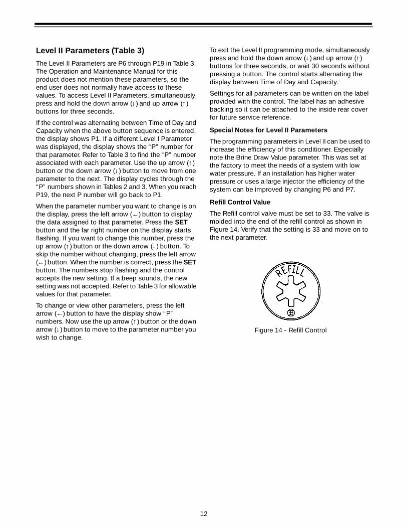
Refill Control Value
The Refill control valve must be set to 33. The valve is molded into the end of the refill control as shown in Figure 14. Verify that the setting is 33 and move on to the next parameter.
Figure 14 - Refill Control
13
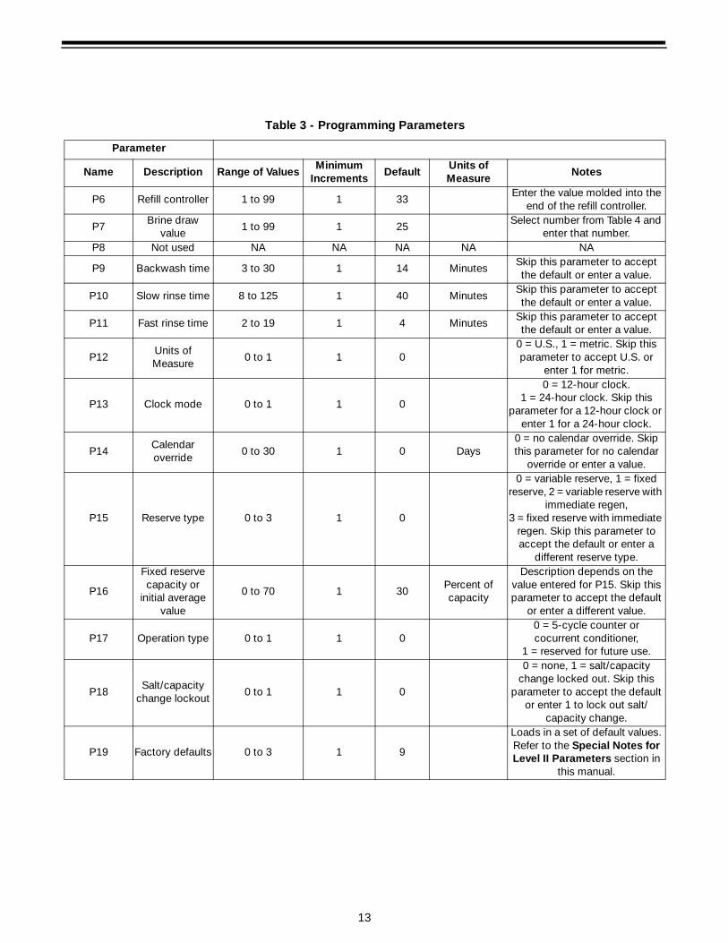
Table 3 - Programming Parameters
Parameter
Name Description Range of ValuesMinimum
IncrementsDefault
Units of Measure
Notes
P6 Refill controller 1 to 99 1 33Enter the value molded into the
end of the refill controller.
P7Brine draw
value1 to 99 1 25
Select number from Table 4 and enter that number.
P8 Not used NA NA NA NA NA
P9 Backwash time 3 to 30 1 14 MinutesSkip this parameter to accept the default or enter a value.
P10 Slow rinse time 8 to 125 1 40 MinutesSkip this parameter to accept the default or enter a value.
P11 Fast rinse time 2 to 19 1 4 MinutesSkip this parameter to accept the default or enter a value.
P12Units of Measure
0 to 1 1 00 = U.S., 1 = metric. Skip this parameter to accept U.S. or
enter 1 for metric.
P13 Clock mode 0 to 1 1 0
0 = 12-hour clock. 1 = 24-hour clock. Skip this
parameter for a 12-hour clock or enter 1 for a 24-hour clock.
P14Calendar override
0 to 30 1 0 Days0 = no calendar override. Skip this parameter for no calendar
override or enter a value.
P15 Reserve type 0 to 3 1 0
0 = variable reserve, 1 = fixed reserve, 2 = variable reserve with
immediate regen, 3 = fixed reserve with immediate
regen. Skip this parameter to accept the default or enter a
different reserve type.
P16
Fixed reserve capacity or
initial average value
0 to 70 1 30Percent of capacity
Description depends on the value entered for P15. Skip this parameter to accept the default
or enter a different value.
P17 Operation type 0 to 1 1 00 = 5-cycle counter or cocurrent conditioner,
1 = reserved for future use.
P18Salt/capacity
change lockout0 to 1 1 0
0 = none, 1 = salt/capacity change locked out. Skip this
parameter to accept the default or enter 1 to lock out salt/
capacity change.
P19 Factory defaults 0 to 3 1 9
Loads in a set of default values. Refer to the Special Notes for Level II Parameters section in
this manual.
14
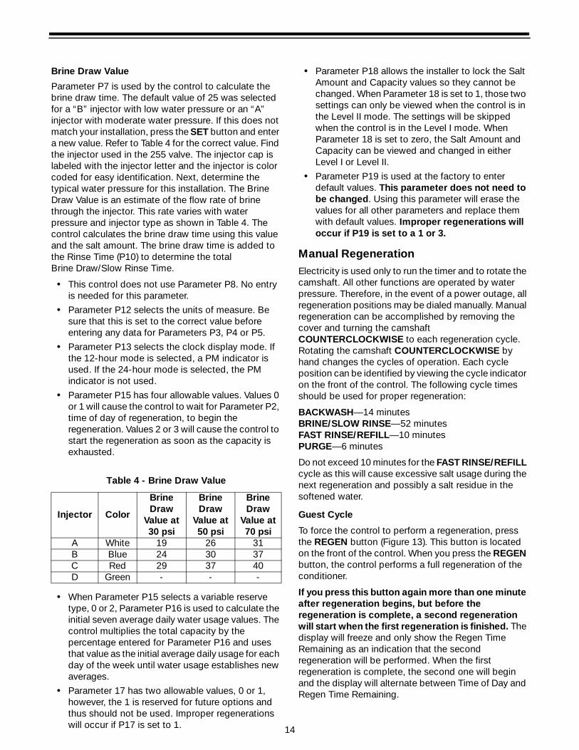
Brine Draw Value
Parameter P7 is used by the control to calculate the brine draw time. The default value of 25 was selected for a “B” injector with low water pressure or an “A” injector with moderate water pressure. If this does not match your installation, press the SET button and enter a new value. Refer to Table 4 for the correct value. Find the injector used in the 255 valve. The injector cap is labeled with the injector letter and the injector is color coded for easy identification. Next, determine the typical water pressure for this installation. The Brine Draw Value is an estimate of the flow rate of brine through the injector. This rate varies with water pressure and injector type as shown in Table 4. The control calculates the brine draw time using this value and the salt amount. The brine draw time is added to the Rinse Time (P10) to determine the total Brine Draw/Slow Rinse Time.
• This control does not use Parameter P8. No entry is needed for this parameter.
• Parameter P12 selects the units of measure. Be sure that this is set to the correct value before entering any data for Parameters P3, P4 or P5.
• Parameter P13 selects the clock display mode. If the 12-hour mode is selected, a PM indicator is used. If the 24-hour mode is selected, the PM indicator is not used.
• Parameter P15 has four allowable values. Values 0 or 1 will cause the control to wait for Parameter P2, time of day of regeneration, to begin the regeneration. Values 2 or 3 will cause the control to start the regeneration as soon as the capacity is exhausted.
• When Parameter P15 selects a variable reserve type, 0 or 2, Parameter P16 is used to calculate the initial seven average daily water usage values. The control multiplies the total capacity by the percentage entered for Parameter P16 and uses that value as the initial average daily usage for each day of the week until water usage establishes new averages.
• Parameter 17 has two allowable values, 0 or 1, however, the 1 is reserved for future options and thus should not be used. Improper regenerations will occur if P17 is set to 1.
• Parameter P18 allows the installer to lock the Salt Amount and Capacity values so they cannot be changed. When Parameter 18 is set to 1, those two settings can only be viewed when the control is in the Level II mode. The settings will be skipped when the control is in the Level I mode. When Parameter 18 is set to zero, the Salt Amount and Capacity can be viewed and changed in either Level I or Level II.
• Parameter P19 is used at the factory to enter default values. This parameter does not need to be changed. Using this parameter will erase the values for all other parameters and replace them with default values. Improper regenerations will occur if P19 is set to a 1 or 3.
Manual RegenerationElectricity is used only to run the timer and to rotate the camshaft. All other functions are operated by water pressure. Therefore, in the event of a power outage, all regeneration positions may be dialed manually. Manual regeneration can be accomplished by removing the cover and turning the camshaft COUNTERCLOCKWISE to each regeneration cycle. Rotating the camshaft COUNTERCLOCKWISE by hand changes the cycles of operation. Each cycle position can be identified by viewing the cycle indicator on the front of the control. The following cycle times should be used for proper regeneration:
BACKWASH—14 minutesBRINE/SLOW RINSE—52 minutes FAST RINSE/REFILL—10 minutesPURGE—6 minutes
Do not exceed 10 minutes for the FAST RINSE/REFILL cycle as this will cause excessive salt usage during the next regeneration and possibly a salt residue in the softened water.
Guest Cycle
To force the control to perform a regeneration, press the REGEN button (Figure 13). This button is located on the front of the control. When you press the REGEN button, the control performs a full regeneration of the conditioner.
If you press this button again more than one minute after regeneration begins, but before the regeneration is complete, a second regeneration will start when the first regeneration is finished. The display will freeze and only show the Regen Time Remaining as an indication that the second regeneration will be performed. When the first regeneration is complete, the second one will begin and the display will alternate between Time of Day and Regen Time Remaining.
Table 4 - Brine Draw Value
Injector Color
Brine Draw
Value at 30 psi
Brine Draw
Value at 50 psi
Brine Draw
Value at 70 psi
A White 19 26 31B Blue 24 30 37C Red 29 37 40D Green - - -
17
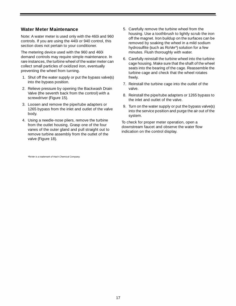
Water Meter MaintenanceNote: A water meter is used only with the 460i and 960 controls. If you are using the 440i or 940 control, this section does not pertain to your conditioner.
The metering device used with the 960 and 460i demand controls may require simple maintenance. In rare instances, the turbine wheel of the water meter can collect small particles of oxidized iron, eventually preventing the wheel from turning.
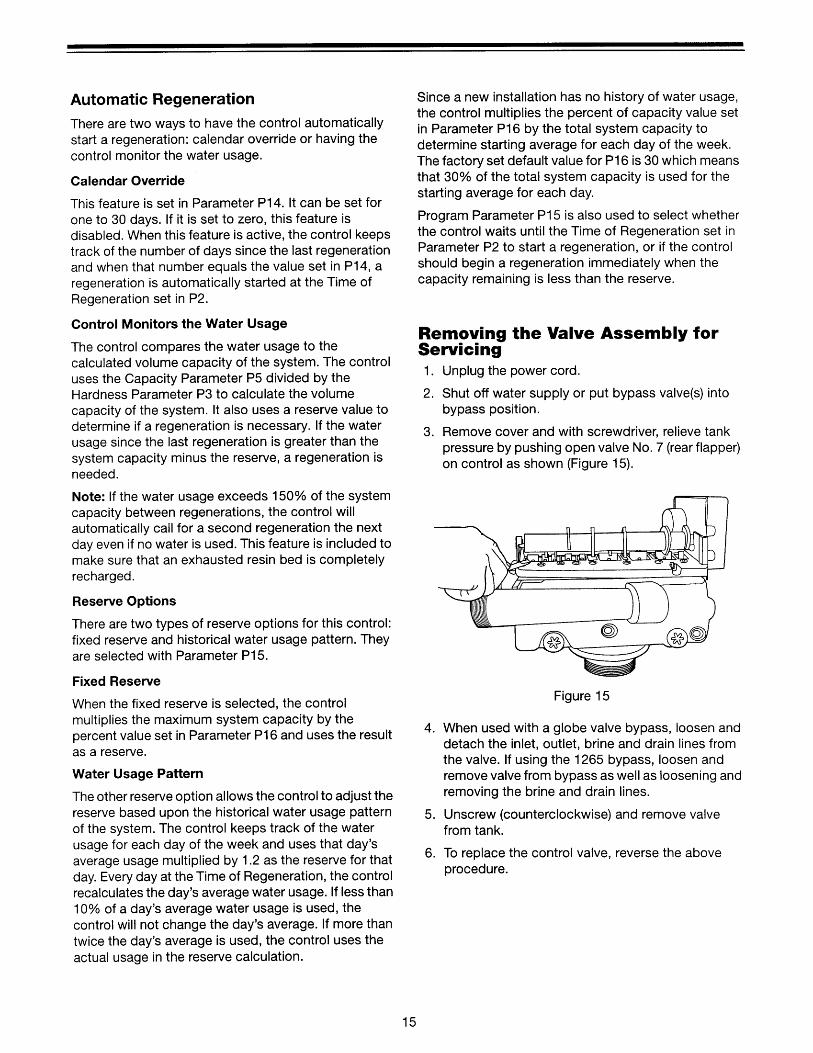
1. Shut off the water supply or put the bypass valve(s) into the bypass position.
2. Relieve pressure by opening the Backwash Drain Valve (the seventh back from the control) with a screwdriver (Figure 15).
3. Loosen and remove the pipe/tube adapters or 1265 bypass from the inlet and outlet of the valve body.
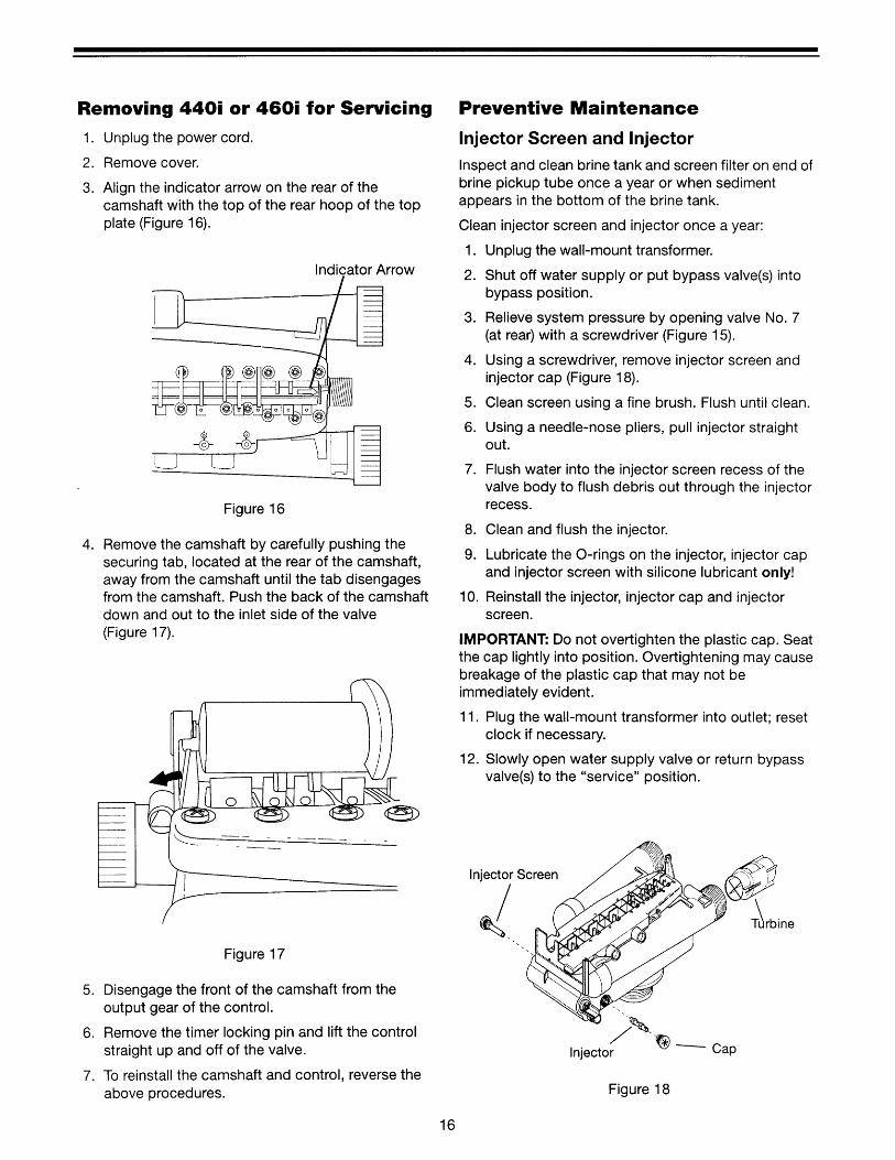
4. Using a needle-nose pliers, remove the turbine from the outlet housing. Grasp one of the four vanes of the outer gland and pull straight out to remove turbine assembly from the outlet of the valve (Figure 18).
5. Carefully remove the turbine wheel from the housing. Use a toothbrush to lightly scrub the iron off the magnet. Iron buildup on the surfaces can be removed by soaking the wheel in a mild sodium hydrosulfite (such as RoVer*) solution for a few minutes. Flush thoroughly with water.
6. Carefully reinstall the turbine wheel into the turbine cage housing. Make sure that the shaft of the wheel seats into the bearing of the cage. Reassemble the turbine cage and check that the wheel rotates freely.
7. Reinstall the turbine cage into the outlet of the valve.
8. Reinstall the pipe/tube adapters or 1265 bypass to the inlet and outlet of the valve.
9. Turn on the water supply or put the bypass valve(s) into the service position and purge the air out of the system.
To check for proper meter operation, open a downstream faucet and observe the water flow indication on the control display.
*RoVer is a trademark of Hach Chemical Company.
18
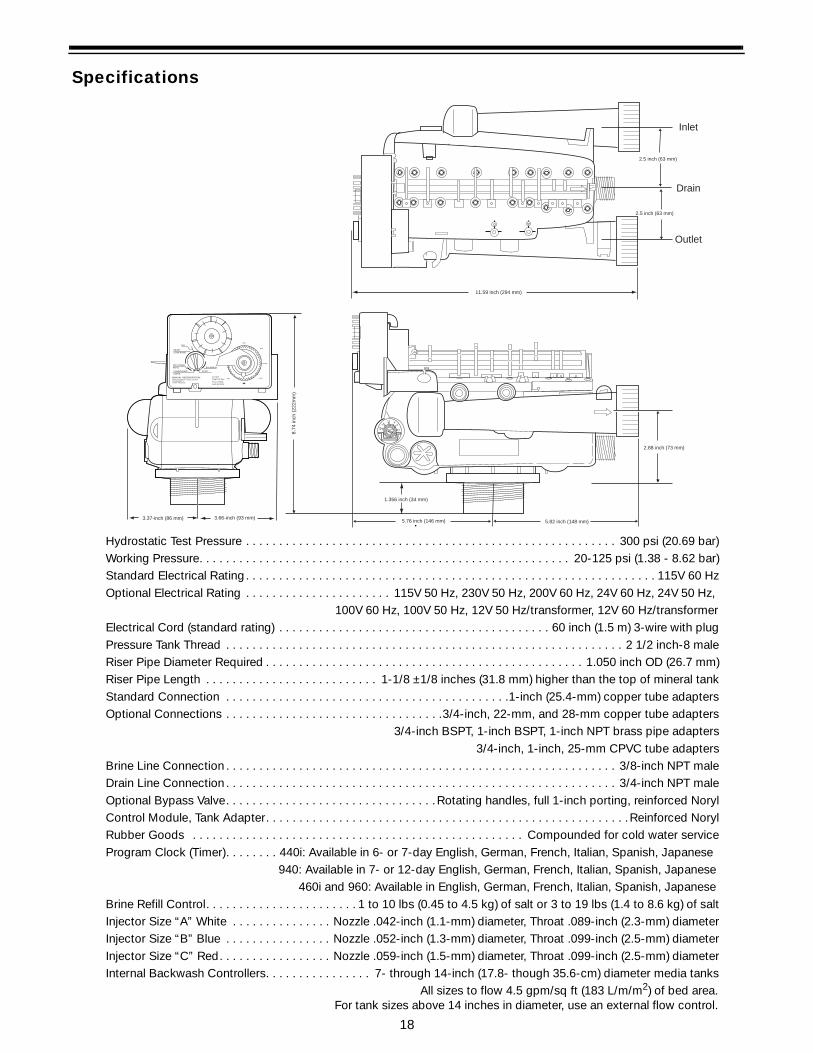
Specifications
Hydrostatic Test Pressure . . . . . . . . . . . . . . . . . . . . . . . . . . . . . . . . . . . . . . . . . . . . . . . . . . . . . . . . 300 psi (20.69 bar)Working Pressure. . . . . . . . . . . . . . . . . . . . . . . . . . . . . . . . . . . . . . . . . . . . . . . . . . . . . . . . 20-125 psi (1.38 - 8.62 bar)Standard Electrical Rating . . . . . . . . . . . . . . . . . . . . . . . . . . . . . . . . . . . . . . . . . . . . . . . . . . . . . . . . . . . . . . 115V 60 HzOptional Electrical Rating . . . . . . . . . . . . . . . . . . . . . . 115V 50 Hz, 230V 50 Hz, 200V 60 Hz, 24V 60 Hz, 24V 50 Hz,
100V 60 Hz, 100V 50 Hz, 12V 50 Hz/transformer, 12V 60 Hz/transformerElectrical Cord (standard rating) . . . . . . . . . . . . . . . . . . . . . . . . . . . . . . . . . . . . . . . . . 60 inch (1.5 m) 3-wire with plugPressure Tank Thread . . . . . . . . . . . . . . . . . . . . . . . . . . . . . . . . . . . . . . . . . . . . . . . . . . . . . . . . . . . . 2 1/2 inch-8 maleRiser Pipe Diameter Required . . . . . . . . . . . . . . . . . . . . . . . . . . . . . . . . . . . . . . . . . . . . . . . . 1.050 inch OD (26.7 mm)Riser Pipe Length . . . . . . . . . . . . . . . . . . . . . . . . . . 1-1/8 ±1/8 inches (31.8 mm) higher than the top of mineral tankStandard Connection . . . . . . . . . . . . . . . . . . . . . . . . . . . . . . . . . . . . . . . . . . .1-inch (25.4-mm) copper tube adaptersOptional Connections . . . . . . . . . . . . . . . . . . . . . . . . . . . . . . . . .3/4-inch, 22-mm, and 28-mm copper tube adapters
3/4-inch BSPT, 1-inch BSPT, 1-inch NPT brass pipe adapters3/4-inch, 1-inch, 25-mm CPVC tube adapters
Brine Line Connection . . . . . . . . . . . . . . . . . . . . . . . . . . . . . . . . . . . . . . . . . . . . . . . . . . . . . . . . . . . 3/8-inch NPT maleDrain Line Connection . . . . . . . . . . . . . . . . . . . . . . . . . . . . . . . . . . . . . . . . . . . . . . . . . . . . . . . . . . . 3/4-inch NPT maleOptional Bypass Valve. . . . . . . . . . . . . . . . . . . . . . . . . . . . . . . .Rotating handles, full 1-inch porting, reinforced NorylControl Module, Tank Adapter. . . . . . . . . . . . . . . . . . . . . . . . . . . . . . . . . . . . . . . . . . . . . . . . . . . . . . .Reinforced NorylRubber Goods . . . . . . . . . . . . . . . . . . . . . . . . . . . . . . . . . . . . . . . . . . . . . . . . . . Compounded for cold water serviceProgram Clock (Timer). . . . . . . . 440i: Available in 6- or 7-day English, German, French, Italian, Spanish, Japanese
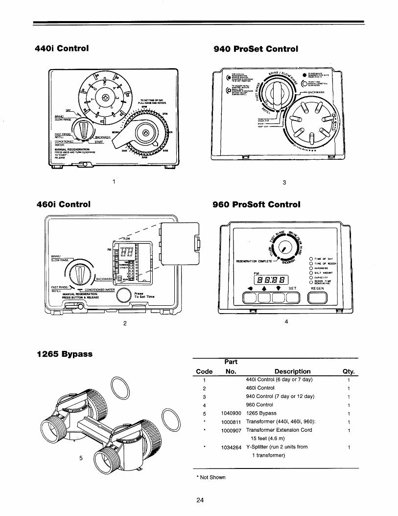
940: Available in 7- or 12-day English, German, French, Italian, Spanish, Japanese460i and 960: Available in English, German, French, Italian, Spanish, Japanese
Brine Refill Control. . . . . . . . . . . . . . . . . . . . . . . 1 to 10 lbs (0.45 to 4.5 kg) of salt or 3 to 19 lbs (1.4 to 8.6 kg) of saltInjector Size “A” White . . . . . . . . . . . . . . . Nozzle .042-inch (1.1-mm) diameter, Throat .089-inch (2.3-mm) diameterInjector Size “B” Blue . . . . . . . . . . . . . . . . Nozzle .052-inch (1.3-mm) diameter, Throat .099-inch (2.5-mm) diameterInjector Size “C” Red. . . . . . . . . . . . . . . . . Nozzle .059-inch (1.5-mm) diameter, Throat .099-inch (2.5-mm) diameterInternal Backwash Controllers. . . . . . . . . . . . . . . . 7- through 14-inch (17.8- though 35.6-cm) diameter media tanks
All sizes to flow 4.5 gpm/sq ft (183 L/m/m2) of bed area.For tank sizes above 14 inches in diameter, use an external flow control.
12 86
3
14
19TO SETTIME OF DAYPULL KNOBAND ROTATE
MANUAL REGENERATION:PRESS KNOB AND TURN COUNTER-CLOCKWISE TO"START"-RELEASE
CONDITIONEDWATER
FAST RINSE/REFILL
BRINE/SLOW RINSE
DAY
BACKWASH
START
NOON
9AM
6AM
3AM
3PM
6PM
3.37-inch (86 mm) 3.66-inch (93 mm)5.76 inch (146 mm) 5.82 inch (148 mm)
2.88 inch (73 mm)
2.5 inch (63 mm)
2.5 inch (63 mm)
11.59 inch (294 mm)
1.356 inch (34 mm)
8.74
inch
(22
2mm
)
Inlet
Outlet
Drain
19
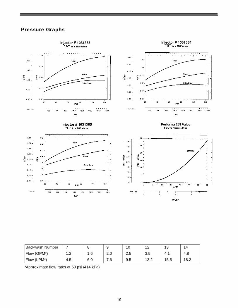
Pressure Graphs
Backwash Number 7 8 9 10 12 13 14
Flow (GPM*) 1.2 1.6 2.0 2.5 3.5 4.1 4.8
Flow (LPM*) 4.5 6.0 7.6 9.5 13.2 15.5 18.2
*Approximate flow rates at 60 psi (414 kPa)


22
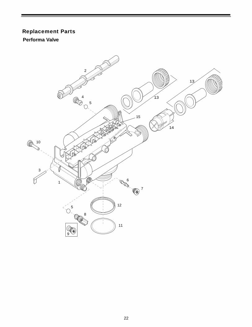
Replacement Parts
2
Performa Valve
4
5
15
10
3
16
7
11
125
8
9
13
13
14
23
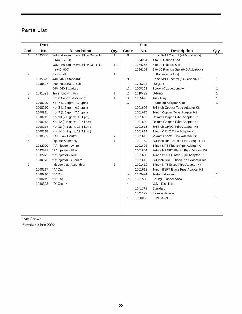
Parts List
* Not Shown
** Available late 2000
Code
Part
No. Description Qty. Code
Part
No. Description Qty.1 1035606 Valve Assembly, w/o Flow Controls 1 8 Brine Refill Control (440i and 460i): 1
(440i, 460i) 1034261 1 to 10 Pounds Salt
Valve Assembly, w/o Flow Controls 1 1034263 3 to 19 Pounds Salt
(940, 960) 1034262 3 to 16 Pounds Salt (940 Adjustable
2 Camshaft: 1 Backwash Only)
1035625 440i, 460i Standard 9 Brine Refill Control (940 and 960): 1
1035627 440i, 460i Extra Salt 1000222 .33 gpm
940, 960 Standard 10 1000226 Screen/Cap Assembly 1
3 1031391 Timer Locking Pin 1 11 1010429 O-Ring 1
4 Drain Control Assembly: 1 12 1035622 Tank Ring 1
1000209 No. 7 (1.2 gpm; 4.5 Lpm) 13 Plumbing Adapter Kits: 1
1000210 No. 8 (1.6 gpm; 6.1 Lpm) 1001606 3/4-inch Copper Tube Adapter Kit
1000211 No. 9 (2.0 gpm; 7.6 Lpm) 1001670 1-inch Copper Tube Adapter Kit
1000212 No. 10 (2.5 gpm; 9.5 Lpm) 1001608 22-mm Copper Tube Adapter Kit
1000213 No. 12 (3.5 gpm; 13.2 Lpm) 1001609 28-mm Copper Tube Adapter Kit
1000214 No. 13 (4.1 gpm; 15.5 Lpm) 1001613 3/4-inch CPVC Tube Adapter Kit
1000215 No. 14 (4.8 gpm; 18.2 Lpm) 1001614 1-inch CPVC Tube Adapter Kit
5 1030502 Ball, Flow Control 2 1001615 25-mm CPVC Tube Adapter Kit
6 Injector Assembly: 1 1001769 3/4-inch NPT Plastic Pipe Adapter Kit
1032970 “A” Injector - White 1001603 1-inch NPT Plastic Pipe Adapter Kit
1032971 “B” Injector - Blue 1001604 3/4-inch BSPT Plastic Pipe Adapter Kit
1032972 “C” Injector - Red 1001605 1-inch BSPT Plastic Pipe Adapter Kit
1030272 “D” Injector - Green** 1001611 3/4-inch BSPT Brass Pipe Adapter Kit
7 Injector Cap Assembly: 1 1001610 1-inch NPT Brass Pipe Adapter Kit
1000217 “A” Cap 1001612 1-inch BSPT Brass Pipe Adapter Kit
1000218 “B” Cap 14 1033444 Turbine Assembly 1
1000219 “C” Cap 15 1001580 Spring, Flapper Valve
1030303 “D” Cap ** * Valve Disc Kit:
1041174 Standard
1041175 Severe Service
* 1000062 I-Lid Cover 1

25
TroubleshootingThe technology upon which the Autotrol Performa control valve is based is well established and proven in service over many years. However, should a problem or question arise regarding the operation of the system, the control can very easily be serviced. For parts mentioned, refer to exploded views in the Replacement Parts section of this manual.
IMPORTANT: Service procedures that require the water pressure to be removed from the system are marked with a ! after the possible cause. To remove water pressure from the system, put the bypass valve or three-valve bypass into the bypass position and open the backwash drain valve (the seventh valve back from the control) with a screwdriver. Restore system water pressure when the service work is completed.
Valve Troubleshooting
Problem Possible Cause Solution1. Control will not draw brine. a. Low water pressure.
b. Restricted drain line.
c. Injector plugged !d. Injector defective !e. Valve (2 and/or 4) not closed.
a. Set pump to maintain 30 psi at conditioner.
b. Remove restriction.
c. Clean injector and screen.
d. Replace injector.
e. Remove foreign matter from disc and check disc for closing by pushing in on stem. Replace if needed.
2. Brine tank overflow. a. Brine valve (1) being held open.
b. Uncontrolled brine refill flow rate !c. Valve (3 or 4) not closed during brine draw
causing refill.
d. Air leak in brine line.
a. Manually operate valve stem to flush away obstruction.
b. Remove variable salt controller to clean.
c. Flush out foreign matter by holding disc open and manually operating valve stem.
d. Check all connections in brine line for leaks. Refer to instructions.
3. System using more or less salt than salt control is set for.
a. Inaccurate setting.
b. Foreign matter in controller causing incorrect flow rates !
c. Defective controller.
a. Correct setting.
b. Remove variable salt controller and flush out foreign matter. Manually position control to brine draw to clean controller (after so doing, position control to “purge” to remove brine from tank).
c. Replace controller.
4. Intermittent or irregular brine draw.
a. Low water pressure.
b. Defective injector !a. Set pump to maintain 30 psi at conditioner.
b. Replace both injector and injector cap.
5. No conditioned water after regeneration.
a. Unit did not regenerate.
b. No salt in brine tank.
c. Plugged injector !
a. Check for power.
b. Add salt.
c. Clean injector. Flush with water.
6. Control backwashes at excessively low or high rate.
a. Incorrect backwash controller used.
b. Foreign matter affecting controller operation !
a. Replace with correct size controller.
b. Remove controller and ball. Flush with water.
7. Flowing or dripping water at drain or brine line after regeneration.
a. Drain valve (5 or 6) or brine valve (1) held open by foreign matter or particle.
b. Valve stem return spring on top plate weak.
a. Manually operate valve stem to flush away obstruction.
b. Replace spring.
8. Hard water leakage during service.
a. Improper regeneration.
b. Leaking of bypass valve !c. O-ring around riser tube
damaged !
a. Repeat regeneration making certain that the correct salt dosage is set.
b. Replace O-ring.
c. Replace O-ring.
26
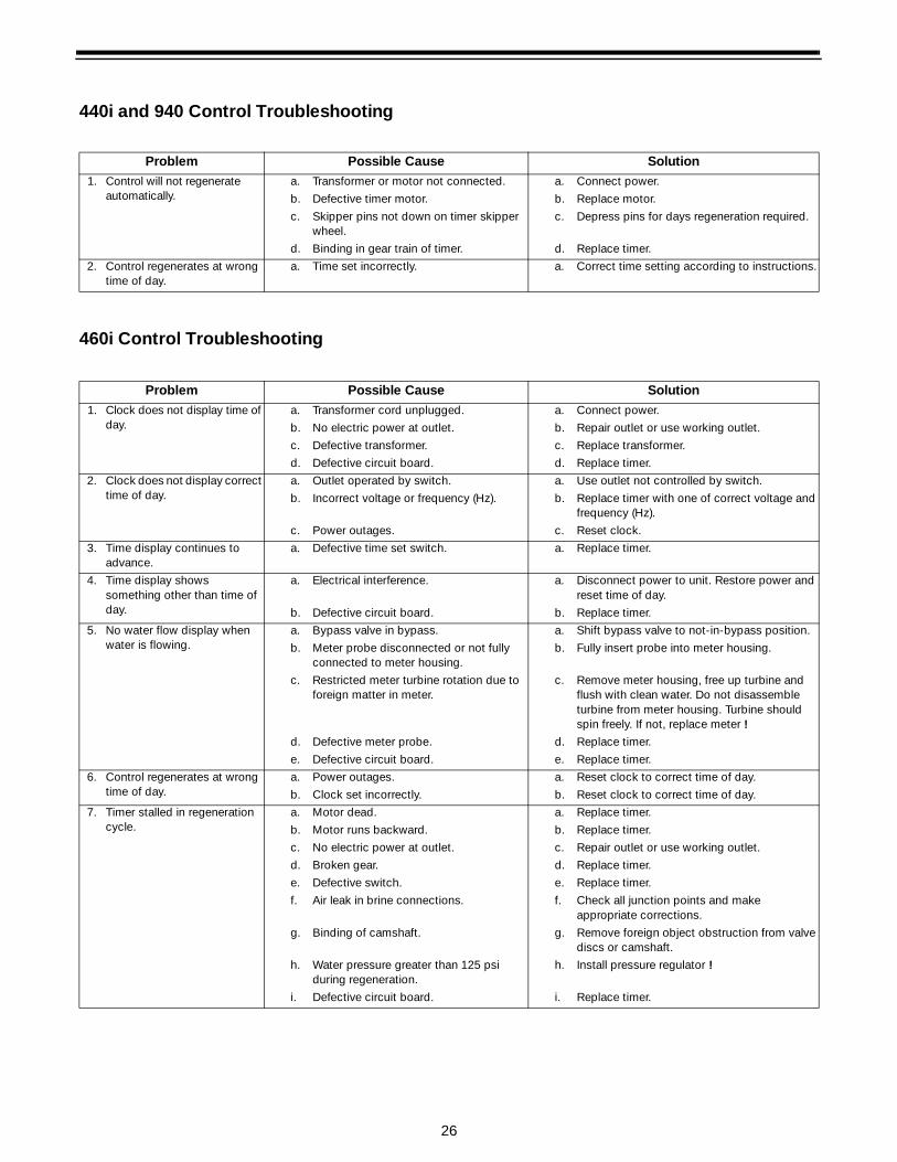
440i and 940 Control Troubleshooting
460i Control Troubleshooting
Problem Possible Cause Solution1. Control will not regenerate
automatically.a. Transformer or motor not connected.
b. Defective timer motor.
c. Skipper pins not down on timer skipper wheel.
d. Binding in gear train of timer.
a. Connect power.
b. Replace motor.
c. Depress pins for days regeneration required.
d. Replace timer.
2. Control regenerates at wrong time of day.
a. Time set incorrectly. a. Correct time setting according to instructions.
Problem Possible Cause Solution1. Clock does not display time of
day.a. Transformer cord unplugged.
b. No electric power at outlet.
c. Defective transformer.
d. Defective circuit board.
a. Connect power.
b. Repair outlet or use working outlet.
c. Replace transformer.
d. Replace timer.
2. Clock does not display correct time of day.
a. Outlet operated by switch.
b. Incorrect voltage or frequency (Hz).
c. Power outages.
a. Use outlet not controlled by switch.
b. Replace timer with one of correct voltage and frequency (Hz).
c. Reset clock.
3. Time display continues to advance.
a. Defective time set switch. a. Replace timer.
4. Time display shows something other than time of day.
a. Electrical interference.
b. Defective circuit board.
a. Disconnect power to unit. Restore power and reset time of day.
b. Replace timer.
5. No water flow display when water is flowing.
a. Bypass valve in bypass.
b. Meter probe disconnected or not fully connected to meter housing.
c. Restricted meter turbine rotation due to foreign matter in meter.
d. Defective meter probe.
e. Defective circuit board.
a. Shift bypass valve to not-in-bypass position.
b. Fully insert probe into meter housing.
c. Remove meter housing, free up turbine and flush with clean water. Do not disassemble turbine from meter housing. Turbine should spin freely. If not, replace meter !
d. Replace timer.
e. Replace timer.
6. Control regenerates at wrong time of day.
a. Power outages.
b. Clock set incorrectly.
a. Reset clock to correct time of day.
b. Reset clock to correct time of day.
7. Timer stalled in regeneration cycle.
a. Motor dead.
b. Motor runs backward.
c. No electric power at outlet.
d. Broken gear.
e. Defective switch.
f. Air leak in brine connections.
g. Binding of camshaft.
h. Water pressure greater than 125 psi during regeneration.
i. Defective circuit board.
a. Replace timer.
b. Replace timer.
c. Repair outlet or use working outlet.
d. Replace timer.
e. Replace timer.
f. Check all junction points and make appropriate corrections.
g. Remove foreign object obstruction from valve discs or camshaft.
h. Install pressure regulator !
i. Replace timer.
28
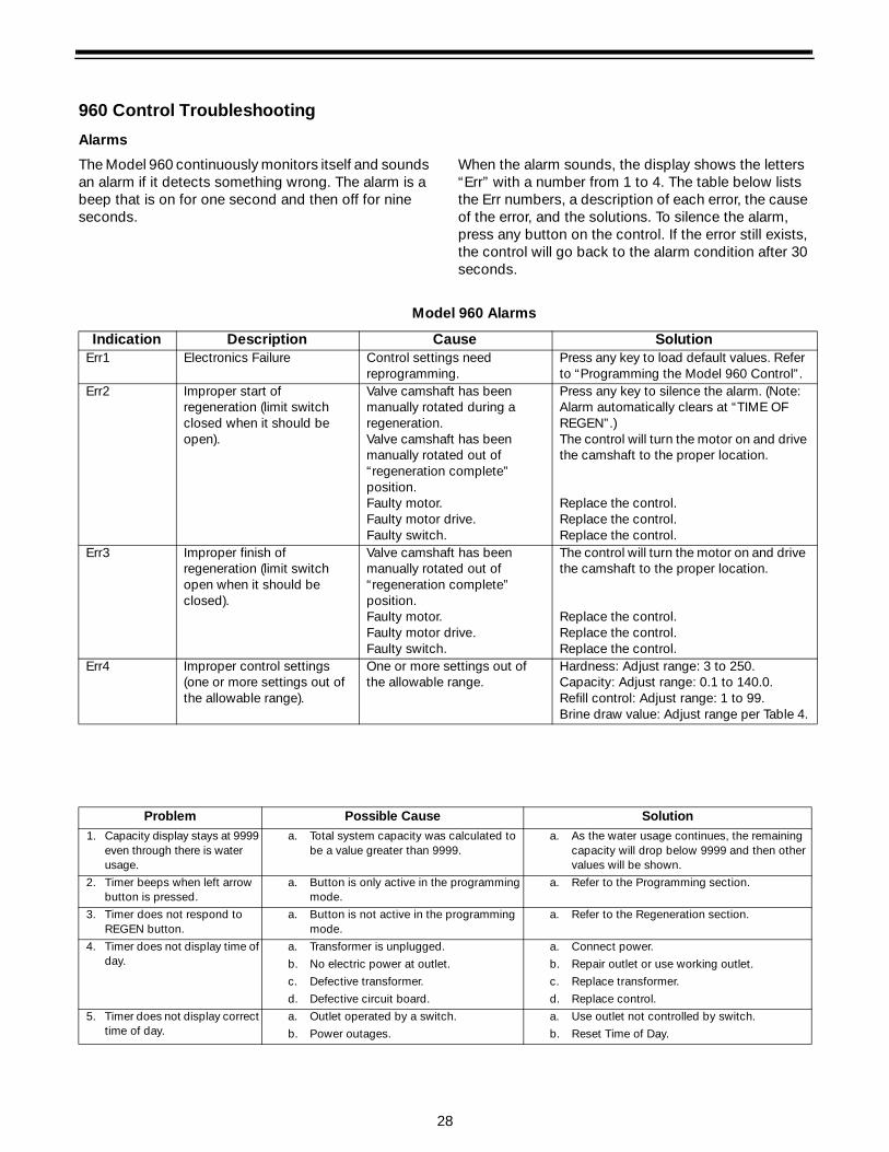
960 Control Troubleshooting
Alarms
The Model 960 continuously monitors itself and sounds an alarm if it detects something wrong. The alarm is a beep that is on for one second and then off for nine seconds.
When the alarm sounds, the display shows the letters “Err” with a number from 1 to 4. The table below lists the Err numbers, a description of each error, the cause of the error, and the solutions. To silence the alarm, press any button on the control. If the error still exists, the control will go back to the alarm condition after 30 seconds.
Model 960 Alarms
Indication Description Cause SolutionErr1 Electronics Failure Control settings need
reprogramming.Press any key to load default values. Refer to “Programming the Model 960 Control”.
Err2 Improper start of regeneration (limit switch closed when it should be open).
Valve camshaft has been manually rotated during a regeneration.Valve camshaft has been manually rotated out of “regeneration complete” position.Faulty motor.Faulty motor drive.Faulty switch.
Press any key to silence the alarm. (Note: Alarm automatically clears at “TIME OF REGEN”.)The control will turn the motor on and drive the camshaft to the proper location.
Replace the control.Replace the control.Replace the control.
Err3 Improper finish of regeneration (limit switch open when it should be closed).
Valve camshaft has been manually rotated out of “regeneration complete” position. Faulty motor.Faulty motor drive.Faulty switch.
The control will turn the motor on and drive the camshaft to the proper location.
Replace the control.Replace the control.Replace the control.
Err4 Improper control settings (one or more settings out of the allowable range).
One or more settings out of the allowable range.
Hardness: Adjust range: 3 to 250.Capacity: Adjust range: 0.1 to 140.0.Refill control: Adjust range: 1 to 99.Brine draw value: Adjust range per Table 4.
Problem Possible Cause Solution1. Capacity display stays at 9999
even through there is water usage.
a. Total system capacity was calculated to be a value greater than 9999.
a. As the water usage continues, the remaining capacity will drop below 9999 and then other values will be shown.
2. Timer beeps when left arrow button is pressed.
a. Button is only active in the programming mode.
a. Refer to the Programming section.
3. Timer does not respond to REGEN button.
a. Button is not active in the programming mode.
a. Refer to the Regeneration section.
4. Timer does not display time of day.
a. Transformer is unplugged.
b. No electric power at outlet.
c. Defective transformer.
d. Defective circuit board.
a. Connect power.
b. Repair outlet or use working outlet.
c. Replace transformer.
d. Replace control.
5. Timer does not display correct time of day.
a. Outlet operated by a switch.
b. Power outages.
a. Use outlet not controlled by switch.
b. Reset Time of Day.
29
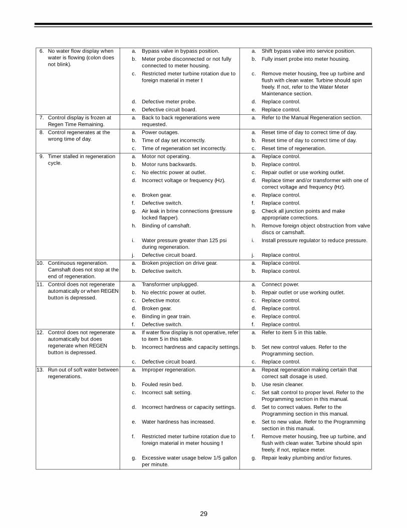
6. No water flow display when water is flowing (colon does not blink).
a. Bypass valve in bypass position.
b. Meter probe disconnected or not fully connected to meter housing.
c. Restricted meter turbine rotation due to foreign material in meter !
d. Defective meter probe.
e. Defective circuit board.
a. Shift bypass valve into service position.
b. Fully insert probe into meter housing.
c. Remove meter housing, free up turbine and flush with clean water. Turbine should spin freely. If not, refer to the Water Meter Maintenance section.
d. Replace control.
e. Replace control.
7. Control display is frozen at Regen Time Remaining.
a. Back to back regenerations were requested.
a. Refer to the Manual Regeneration section.
8. Control regenerates at the wrong time of day.
a. Power outages.
b. Time of day set incorrectly.
c. Time of regeneration set incorrectly.
a. Reset time of day to correct time of day.
b. Reset time of day to correct time of day.
c. Reset time of regeneration.
9. Timer stalled in regeneration cycle.
a. Motor not operating.
b. Motor runs backwards.
c. No electric power at outlet.
d. Incorrect voltage or frequency (Hz).
e. Broken gear.
f. Defective switch.
g. Air leak in brine connections (pressure locked flapper).
h. Binding of camshaft.
i. Water pressure greater than 125 psi during regeneration.
j. Defective circuit board.
a. Replace control.
b. Replace control.
c. Repair outlet or use working outlet.
d. Replace timer and/or transformer with one of correct voltage and frequency (Hz).
e. Replace control.
f. Replace control.
g. Check all junction points and make appropriate corrections.
h. Remove foreign object obstruction from valve discs or camshaft.
i. Install pressure regulator to reduce pressure.
j. Replace control.
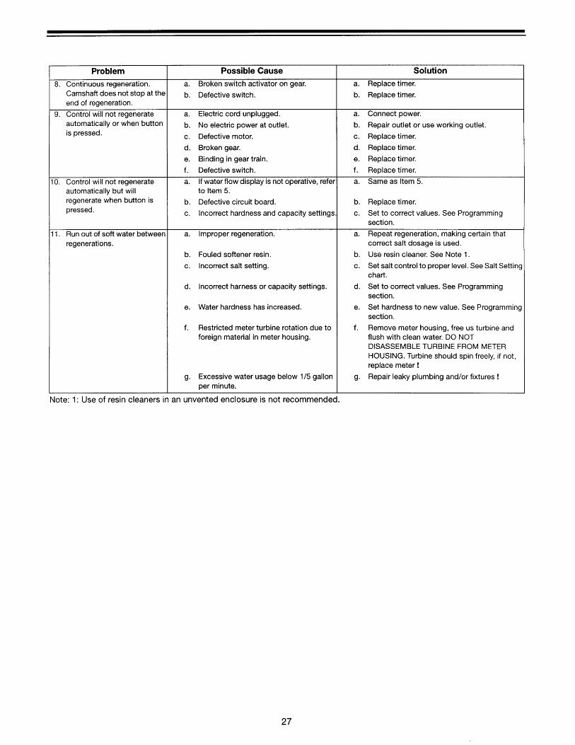
10. Continuous regeneration. Camshaft does not stop at the end of regeneration.
a. Broken projection on drive gear.
b. Defective switch.
a. Replace control.
b. Replace control.
11. Control does not regenerate automatically or when REGEN button is depressed.
a. Transformer unplugged.
b. No electric power at outlet.
c. Defective motor.
d. Broken gear.
e. Binding in gear train.
f. Defective switch.
a. Connect power.
b. Repair outlet or use working outlet.
c. Replace control.
d. Replace control.
e. Replace control.
f. Replace control.
12. Control does not regenerate automatically but does regenerate when REGEN button is depressed.
a. If water flow display is not operative, refer to item 5 in this table.
b. Incorrect hardness and capacity settings.
c. Defective circuit board.
a. Refer to item 5 in this table.
b. Set new control values. Refer to the Programming section.
c. Replace control.
13. Run out of soft water between regenerations.
a. Improper regeneration.
b. Fouled resin bed.
c. Incorrect salt setting.
d. Incorrect hardness or capacity settings.
e. Water hardness has increased.
f. Restricted meter turbine rotation due to foreign material in meter housing !
g. Excessive water usage below 1/5 gallon per minute.
a. Repeat regeneration making certain that correct salt dosage is used.
b. Use resin cleaner.
c. Set salt control to proper level. Refer to the Programming section in this manual.
d. Set to correct values. Refer to the Programming section in this manual.
e. Set to new value. Refer to the Programming section in this manual.
f. Remove meter housing, free up turbine, and flush with clean water. Turbine should spin freely, if not, replace meter.
g. Repair leaky plumbing and/or fixtures.
30
Disinfection of Water ConditionersThe materials of construction of the modern water conditioner will not support bacterial growth, nor will these materials contaminate a water supply. However, the normal conditions existing during shipping, storage and installation indicate the advisability of disinfecting a conditioner after installation, before the conditioner is used to treat potable water. In addition, during normal use, a conditioner may become fouled with organic matter or in some cases with bacteria from the water supply.
Thus every conditioner should be disinfected after installation, some will require periodic disinfection during their normal life, and in a few cases disinfection with every regeneration would be recommended.
Depending upon the conditions of use, the style of conditioner, the type of ion exchanger, and the disinfectant available, a choice can be made among the following methods.
Sodium or Calcium HypochloriteApplication
These materials are satisfactory for use with polystyrene resins, synthetic gel zeolite, greensand and bentonites.
5.25% Sodium Hypochlorite
These solutions are available under trade names such as Clorox Bleach*. If stronger solutions are used, such as those sold for commercial laundries, adjust the dosage accordingly.
1. Dosage
a. Polystyrene resin: 1.2 fluid ounces per cubic foot.
b. Non-resinous exchangers: 0.8 fluid ounce per cubic foot.
2. Brine tank conditioners
a. Backwash the conditioner and add the required amount of hypochlorite solution to the brine well of the brine tank. (The brine tank should have water in it to permit the solution to be carried into the conditioner.)
b. Proceed with the normal regeneration.
Calcium HypochloriteCalcium hypochlorite, 70% available chlorine, is available in several forms including tablets and granules. These solid materials may be used directly without dissolving before use.
1. Dosage
a. Two grains (approximately 0.1 ounce) per cubic foot.
2. Brine tank conditioners
a. Backwash the conditioner and add the required amount of hypochlorite to the brine well of the brine tank. (The brine tank should have water in it to permit the chlorine solution to be carried into the conditioner.)
b. Proceed with the normal regeneration.
*Clorox is a registered trademark of The Clorox Company.

31

© Copyright 2000 OsmonicsPrinted in USA P/N 1222945 Rev. A