Embed Size (px)
Citation preview
Document downloaded from:
This paper must be cited as:
The final publication is available at
Copyright
Additional Information
http://dx.doi.org/10.1016/j.ijrefrig.2014.04.015
http://hdl.handle.net/10251/58842
Elsevier
Mota Babiloni, A.; Navarro Esbri, J.; Barragán Cervera, Á.; Moles Ribera, F.; Peris Pérez, B.(2014). Theoretical comparison of low GWP alternatives for different refrigerationconfigurations taking R404A as baseline. International Journal of Refrigeration. 44:81-90.doi:10.1016/j.ijrefrig.2014.04.015.
1
Theoretical comparison of low GWP alternatives for different refrigeration
configurations taking R404A as baseline
Adrián Mota-Babilonia,b
, Joaquín Navarro-Esbríb,
, Ángel Barragánb, Francisco Molés
b,
Bernardo Perisb
a Institute for Industrial, Radiophysical and Environmental Safety, Camino de Vera s/n,
Polytechnic University of Valencia, E-46022 Valencia, Spain.
b ISTENER Research Group. Department of Mechanical Engineering and Construction,
Campus de Riu Sec s/n, University Jaume I, E12071, Castellón, Spain.
Abstract
Six refrigerants are evaluated as low GWP replacements for R404A using different
configurations, including two-stage system architectures. These refrigerants are selected
according to similar characteristics to R404A, and they are the mid-term alternatives
R407A and R407F, and the long-term alternatives: L40 and DR-7 (with very low GWP
and low flammability), N40 and DR-33 (with low GWP and no flammability). In order
to have a complete comparison range, various operating conditions are considered,
covering low and medium evaporator temperatures and two levels of condensation
temperatures. Configurations selected are presented and the equations used to simulate
the expected performance are shown. From a given cooling capacity, volumetric flow
rate and COP are compared, taking R404A as baseline. The most efficient alternatives
are the low-flammable refrigerants, L40 and DR-7, and when no flammability is
acceptable, N40 and DR-33 are also very good options.
Keywords: refrigeration; configurations; R404A replacements; GWP; Coefficient of
Performance.
Nomenclature
𝐶𝑂𝑃 coefficient of performance (-)
ℎ specific enthalpy (kJ kg-1
)
�̇� refrigerant mass flow rate (kg s-1
)
𝑃 pressure (MPa)
�̇� heat transfer rate (kW)
𝑆𝐻 Superheating degree (ºC)
𝑇 temperature (ºC)
Corresponding Author:
Tel: +34 964728137; fax: +34 964728106.
E-mail address: [email protected]
2
�̇� volumetric flow rate (m3 s
-1)
�̇�𝑐 compressor power consumption (kW)
Greek symbols
𝜀 effectiveness
𝜂 efficiency
𝜌 density (kg m-3
)
Subscripts
𝑑𝑖𝑠𝑐 discharge
𝐻𝑃 high pressure stage
𝐼𝐻𝑋 Intermediate Heat Exchanger
𝑖𝑛 inlet
𝐼𝑃 intermediate pressure stage
𝑘 condenser
𝑙𝑖𝑞 saturated liquid
𝐿𝑃 low pressure stage
𝑜𝑢𝑡 outlet
𝑠𝑢𝑐 suction
𝑆𝐶 subcooler
𝑜 evaporator
1. Introduction
To avoid the reduction in the atmospheric ozone, according to the terms of the Montreal
Protocol, a total phase-out for chlorofluorocarbon (CFC) by 2010 and
hydrochlorofluorcarbon (HCFC) by 2040 in all countries [1] has been established. In
this way, hydrofluorocarbon (HFC) gases became relevant in all refrigeration fields [2]
because of their zero Ozone Depletion Potential (ODP). And while they are non-ozone
depleting substances, they have great values of global warming potential (GWP). So,
after being approved the Kyoto Protocol in 1997 [3], HFC refrigerants were considered
as greenhouse gases (GHGs) and they would be progressively removed.
3
Through the European Directive 2006/40/EC [4] fluids with GWP>150 are banned for
new mobile air conditioners (MAC) since 2011 and for the rest MAC systems will be
excluded onward 2017. Additionally, in 2012 a tightening of the F-gas regulation was
proposed, where a reduction reaching 21% of the levels sold in 2008-2011 by 2030 is
established. In this way, in 2013 in Spain, it a tax focused on refrigerants with high
GWP [5] was also approved.
So, because of the relevance of the refrigerant gas leakages from vapour compression
systems (in UK supermarkets around 13% of refrigerant from circuits is lost [6]),
research efforts in refrigeration industry are focused on finding non-toxic fluids with
low GWP and with low flammability to replace high GWP working fluids used in
existing vapour compression cycles [7].
Analyzing low and medium temperature commercial refrigeration applications, due to
Montreal Protocol there was a retrofit process from R22 and R502 to zero-ODP
refrigerants, mainly R134a, R404A and R507A [8, 9]. R404A and R507A are very
similar and they can be used both for a very wide range of evaporation temperatures,
R404A being mostly used in Europe. R404A shows excellent properties: non-
flammable and non-toxic, easy retrofit in R22 systems, a similar range of operating
conditions and presents good energy efficiencies [10-14]. However, R404A presents
high GWP (3922) [15] and probably is going to be phase-out over the next years [16].
Currently, HFC mixtures are prevailing as medium GWP replacements for R404A. In
this way, non-flammable mid-term solutions like R407A (GWP=2107) or R407F
(GWP=1825) are available [17, 18]. Despite having half the GWP of R404A, these
refrigerants are presented with a better performance in light retrofit processes. In order
to work with refrigerants with even lower GWP values, long-term solutions are being
developed by Honeywell (Solstice™ N40 and L40) [19] or DuPont (DR-7 and DR-33)
[20], developing HFC and HFO blends.
While N40 and DR-33 are non-flammable refrigerants with relatively-low GWP values
(1205 and 1410, respectively), L40 and DR-7 have a low value of GWP (285 and 246,
respectively) even though they would be classified as A2L by ASHRAE Standard 34
[21]. Yana Motta et al [22] suggest using in future studies flammable refrigerants in
high side of secondary fluid systems (chillers), cascade systems (CO2 in the low stage),
small close-coupled systems, and even distributed systems.
Moreover, Yana Motta et al [22] tested low GWP refrigerants (R407F, N40, N20 and
L40) in a refrigeration system designed for R404A. All alternatives showed superior
performance, acceptable pressures and discharge temperatures below the limits. On the
other hand, they recommended some changes when using flammable refrigerants.
Minor et al [20] experimented with DR-7 and DR-33 in a double-door unit designed for
R-404A. The conclusions were that both replacements presented similar (DR-33) or
slightly minor (DR-7) energy consumption, similar pressures and compression ratio,
and the increase in discharge temperature was about 13-16ºC.
Besides using low GWP alternatives, it is also important to look for more efficient
systems. In this way, applying some modifications to the basic cycle [23] should be
considered. For example, the refrigerating effect in the evaporator can be enhanced
4
using an internal heat exchanger (IHX) [24]. By introducing an ejector expansion cycle
an increment in 𝐶𝑂𝑃 parameter can be achieved [25], or expanders can ever be
considered to reduce system energy consumption thanks to expansion work recovery
[26]. With two-stage systems, several configurations can be taken into account by the
introduction of a flash tank or a subcooler at the intermediate stage or injecting a
mixture of liquid and vapour in the discharge of the low pressure compressor [27] or
even applying modifications of one-stage system as an IHX and/or an ejector [28]. It
has been demonstrated that although the systems developed are more complex, higher
efficiencies can be reached and discharge temperature considerably reduced by allowing
cycles working at higher compression rates.
Therefore, the aim of this work is to compare theoretically the energy performance of
four vapour compression refrigeration configurations using R404A and low GWP
refrigerants R407A, R407F, L40, DR-7, N40 and DR-33 as alternative fluids. This
paper is organised as follows: In Section 2, the main properties of the chosen working
fluids are exposed. In Section 3, the proposed configurations are presented. In Section 4,
the equations used to obtain the expected performance are introduced. In Section 5, the
results are shown and discussed. Finally, Section 6 summarizes the main conclusions of
the work.
2. Working fluids
As said before, this study focuses on comparing R404A with low GWP alternatives.
The finally selected refrigerants also have to accomplish other characteristics as thermal
stability, low flammability and low toxicity. Furthermore, when those alternative
refrigerants have to be retrofitted into a R404A vapour compression plant, similar
working conditions to R404A and oil compatibility are required. The selected
refrigerants are classified as commercial mid-term alternatives (medium GWP), R407A
and R407F, and long-term alternatives, refrigerants that are being developed nowadays.
Long-term alternatives are sub-classified as flammable refrigerants (very low GWP),
L40 and DR-7, and non-flammable refrigerants (medium low GWP), N40 and DR-33.
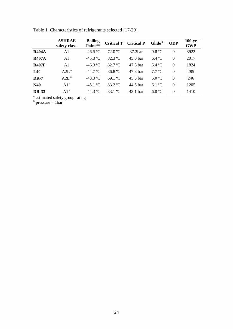
First, in Table 1, main characteristics of the selected refrigerants are summarised, taking
R407A [17] and R407F [18] as R404A mid-term replacements, Honeywell L40 and
N40 [19], Dupont DR-7 and DR-33 [20] as long-term alternatives. It can be seen that
alternative refrigerants show similar properties to R404A, and the following conclusions
can be extracted when they are compared with R404A:
Similar boiling point, with the exception of DR-7 that has an approximately 3ºC
higher.
Higher critical temperature: approx. 15% higher for R407A, R407F, N40 and
DR-33; 21% greater L40 and 4% smaller for DR-7.
Higher critical Pressure: from 15% for DR-33 up to 27% for L40.
The replacements have a higher glide value that makes this effect non
depreciable when configurations with a flash tank are considered. From 5ºC for
DR-7 up to 7.7ºC for L40.
All the alternatives provide important GWP reduction.
5
Table 1. Characteristics of refrigerants selected [17-20].
3. Configurations selected
In this paper four vapour compression configurations are considered: Basic cycle (BC),
Basic cycle with Internal Heat Exchanger (BCIHX), Direct Injection (DI) and
Subcooler Cycle (SC).
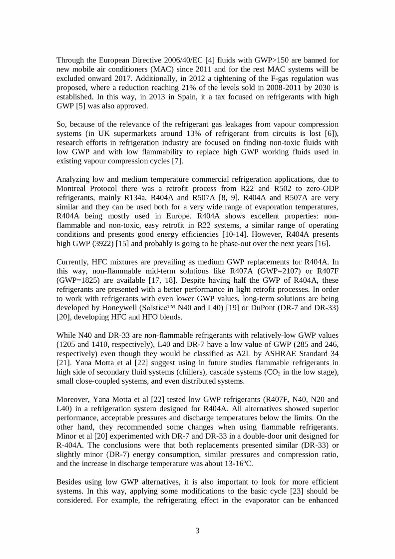
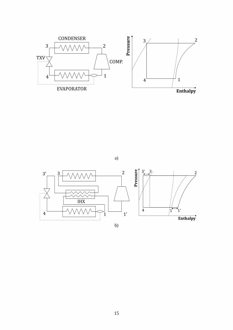
The first configuration presented is Basic cycle, Fig. 1.a). It consists of the basic
elements: condenser, expansion valve, evaporator and compressor. Modifying this
configuration the other configurations analysed in this work are obtained.
Fig. 1.a) Diagram and P-h cycle of configurations. Basic Cycle.
Basic cycle with IHX configuration is achieved by adding a heat exchanger between the
suction and the liquid line, Fig. 1.b). Cooling the liquid line, the refrigerant entering in
the evaporator has a lower enthalpy, and the refrigerating effect in it is greater. On the
other hand, suction gas is heated causing higher gas discharge temperature; besides
compressor consumption is increased. Finally, the 𝐶𝑂𝑃 variation could be positive or
negative, depending on the studied refrigerant.
Fig. 1.b) Diagram and P-h cycle of configurations. Basic Cycle with IHX.
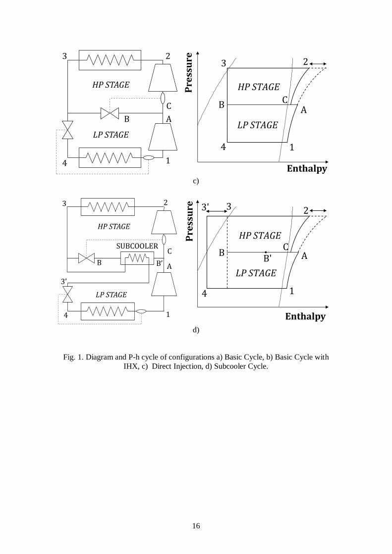
The introduction of two-stage cycles reports an increase in the cycle efficiency and
decrease the discharge temperature. Another consequence is the increment in the mass
flow rate in the high-pressure stage compressor. It must be noted that those
configurations with flash tank are not considered in this work due to the high glide
presented by the alternative refrigerants analyzed.
By injecting refrigerant at intermediate pressure in the discharge of the low pressure
compressor the Direct Injection configuration can be obtained, Fig. 1.c).
Fig. 1.c) Diagram and P-h cycle of configurations. Direct Injection.
Finally, Subcooler Cycle configuration is the more complex configuration analysed, in
terms of construction. It is brought off using a heat exchanger (subcooler) that uses a
part of refrigerant derived at intermediate pressure to cool the rest of liquid refrigerant,
Fig. 1.d). Then refrigerant at an intermediate pressure is mixed with the discharge gas of
the low pressure compressor. A higher refrigerating effect at the evaporator stage is
reached and the discharge temperature is reduced.
Fig. 1.d) Diagram and P-h cycle of configurations. Subcooler Cycle.
6
4. Simulation conditions and equations applied
In order to model the vapour compression cycle for each configuration, two parameters
are combined trying to simulate working conditions (taking into account glide
considerations [29]):
Average evaporation temperature, 𝑇𝑜: -40ºC (low evaporation temperature) and -
10ºC (medium evaporation temperature).
Average condensation temperature, 𝑇𝑘: 40ºC and 55ºC.
For the refrigerants with high glide values, evaporation and condensation temperatures
are obtained as suggested in [29], Eq. (1) and (2) respectively.
𝑇𝑜 =1
3𝑇𝐵𝑢𝑏𝑏𝑙𝑒 +
2
3𝑇𝐷𝑒𝑤 (1)
𝑇𝑘 =1
2𝑇𝐵𝑢𝑏𝑏𝑙𝑒 +
1
2𝑇𝐷𝑒𝑤 (2)
For following comparisons, target cooling capacity will be constant for all conditions.
Moreover, to complete cycle simulation, following assumptions are taken:
Subcooling degree (at the condenser outlet): 2ºC.
Isenthalpic process is considered at the expansion valve.
Ideal compression (the refrigerants selected are recently developed and there is
no data available about compression performance).
There is no heat transfer to the surroundings.
Pressure drops are neglected.
Heat exchange efficiency in subcooler (𝜀𝑆𝐶): 0.7.
Heat exchange efficiency in IHX (𝜀𝐼𝐻𝑋): 0.3 (in order to avoid high discharge
temperatures).
The total superheating degree (between saturation temperature and compressor suction)
and superheating degree at intermediate pressure (between saturated vapour and the
high pressure compressor suction) for R404A is 7ºC, for the rest of refrigerants is
corrected [29], Eq. (3) and (4):
𝑆𝐻𝑅𝑒𝑓𝑟𝑖𝑔𝑒𝑟𝑎𝑛𝑡 𝑤𝑖𝑡ℎ 𝑔𝑙𝑖𝑑𝑒,𝐿𝑃 = 𝑆𝐻𝑅404𝐴 −1
3𝐺𝑙𝑖𝑑𝑒 (3)
𝑆𝐻𝑅𝑒𝑓𝑟𝑖𝑔𝑒𝑟𝑎𝑛𝑡 𝑤𝑖𝑡ℎ 𝑔𝑙𝑖𝑑𝑒,𝐼𝑃 = 𝑆𝐻𝑅404𝐴 −1
2𝐺𝑙𝑖𝑑𝑒 (4)
The thermodynamic states of refrigerants studied are based on data from REFPROP v. 8
[30].
In two-stage configurations the inter-stage pressure is calculated using Eq. (5),
obtaining the same compression rate in both stages [31].
7
𝑃𝐼𝑃 = √𝑃𝐿𝑃𝑃𝐻𝑃 (5)
The mass flow rate at low pressure stage, �̇�𝐿𝑃, is calculated in Eq. (6).
�̇�𝐿𝑃 =�̇�𝑜
(ℎ𝑜,𝑜𝑢𝑡 − ℎ𝑜,𝑖𝑛) (6)
The volumetric flow rate at suction, �̇�𝑠𝑢𝑐 , is obtained from mass flow rate and density,
Eq. (7).
�̇�𝑠𝑢𝑐 =�̇�
𝜌𝑠𝑢𝑐 (7)
For IHX configuration, Eq. (8) is used to simulate its performance.
𝜀𝐼𝐻𝑋 =𝑇𝑠𝑢𝑐 − 𝑇𝑜,𝑜𝑢𝑡
𝑇𝑘,𝑜𝑢𝑡 − 𝑇𝑜,𝑜𝑢𝑡 (8)
To calculate mass flow rate at the high pressure stage in DI configuration, Eq. (9) is
applied.
�̇�𝐻𝑃 = �̇�𝐿𝑃
(ℎ𝑑𝑖𝑠𝑐,𝐿𝑃 − ℎ𝑘,𝑜𝑢𝑡 )
(ℎ𝑠𝑢𝑐,𝐻𝑃 − ℎ𝑘,𝑜𝑢𝑡) (9)
For SC Configuration �̇�𝐻𝑃 is obtained from Eq. (10), using Eq. (11) to obtain the outlet
enthalpy at the Intermediate Pressure stage.
�̇�𝐻𝑃 = �̇�𝐿𝑃
(ℎ𝑑𝑖𝑠𝑐,𝐿𝑃 − ℎ𝐼𝑃,𝑜𝑢𝑡 )
(ℎ𝑠𝑢𝑐,𝐿𝑃 − ℎ𝐼𝑃,𝑜𝑢𝑡 ) (10)
ℎ𝐼𝑃,𝑜𝑢𝑡 =ℎ𝑘,𝑜𝑢𝑡ℎ𝑑𝑖𝑠𝑐,𝐿𝑃 − ℎ𝑜,𝑖𝑛ℎ𝑠𝑢𝑐,𝐻𝑃
(ℎ𝑘,𝑜𝑢𝑡+ℎ𝑑𝑖𝑠𝑐,𝐿𝑃) − (ℎ𝑜,𝑖𝑛+ℎ𝑠𝑢𝑐,𝐻𝑃) (11)
The Coefficient of Performance, 𝐶𝑂𝑃, is calculated from the cooling capacity at the
evaporator and the compressor power consumption (�̇�𝐶), Eq. (12).
𝐶𝑂𝑃 =�̇�𝑜
�̇�𝐶
(12)
�̇�𝐶 for one-stage configuration is expressed in Eq. (13) as a product of mass flow rate
and the isentropic enthalpy increase at the compressor.
�̇�𝐶 = �̇�𝐿𝑃∆ℎ𝑐 (13)
�̇�𝐶 for two-stage configurations Eq. (14) is applied, separating �̇�𝐶 value in the two
compression stages.
8
�̇�𝐶 = �̇�𝐿𝑃 ∆ℎ𝑐,𝐿𝑃 + �̇�𝐻𝑃 ∆ℎ𝑐,𝐻𝑃 (14)
5. Results and discussion
This section presents the main results of the energetic simulation carried out varying the
evaporation temperature ( 𝑇𝑜 ) and the condensation temperature ( 𝑇𝑘 ) for the four
configurations analysed. As exposed in section 2, refrigerants R407A, R407F, L40, DR-
7, N40 and DR-33 have been developed as low GWP retrofit alternatives for R404A.
COP (parameter commonly used to evaluate energy performance of system) and
volumetric flow rate at compressor suction (it can show the adaptation of the refrigerant
to existing compressor) are the parameters chosen in this study to determine the
suitability of alternatives as retrofit replacements for R404A. Indeed, the results are
shown as a relative difference (%�̇�𝑠𝑢𝑐 and %𝐶𝑂𝑃) of each configuration working with
alternative fluids taking as reference the same configuration working with R404A, as
shown in Eq. (15) and (16).
%�̇�𝑠𝑢𝑐 = (�̇�𝑠𝑢𝑐𝑎𝑙𝑡𝑒𝑟𝑛𝑎𝑡𝑖𝑣𝑒 𝑓𝑙𝑢𝑖𝑑
− �̇�𝑠𝑢𝑐 𝑅404𝐴
�̇�𝑠𝑢𝑐 𝑅404𝐴
) · 100 (15)
%𝐶𝑂𝑃 = (𝐶𝑂𝑃𝑎𝑙𝑡𝑒𝑟𝑛𝑎𝑡𝑖𝑣𝑒 𝑓𝑙𝑢𝑖𝑑 − 𝐶𝑂𝑃𝑅404𝐴
𝐶𝑂𝑃𝑅404𝐴) · 100 (16)
Furthermore, numerical results are shown in Table 2, Table 3 and Table 4.
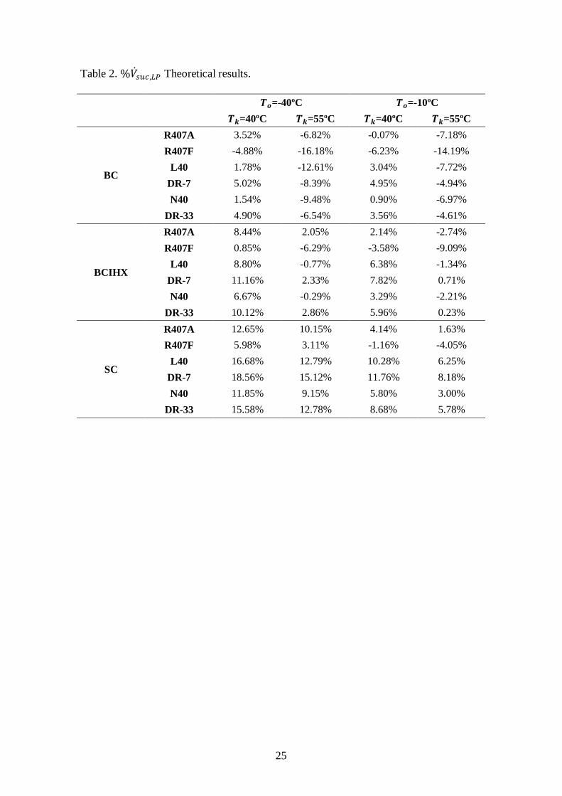
Table 2. %�̇�𝑠𝑢𝑐,𝐿𝑃 Theoretical results.
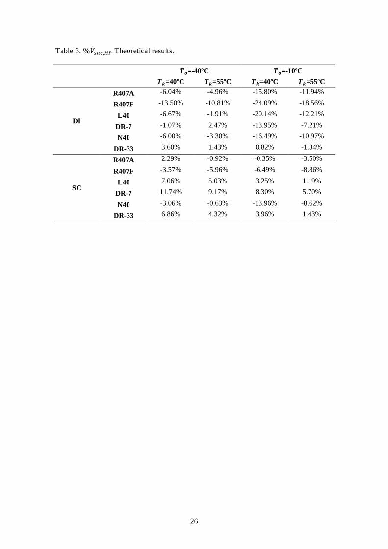
Table 3. %�̇�𝑠𝑢𝑐,𝐻𝑃 Theoretical results.
Table 4. %𝐶𝑂𝑃 Theoretical results.
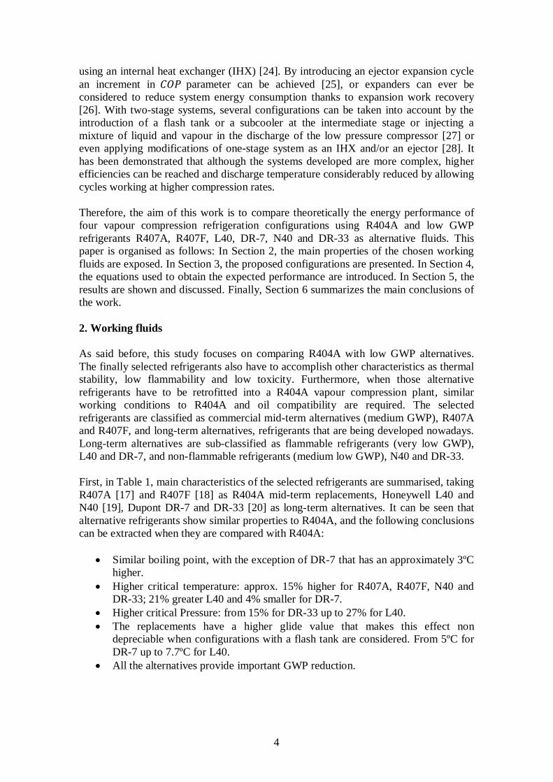
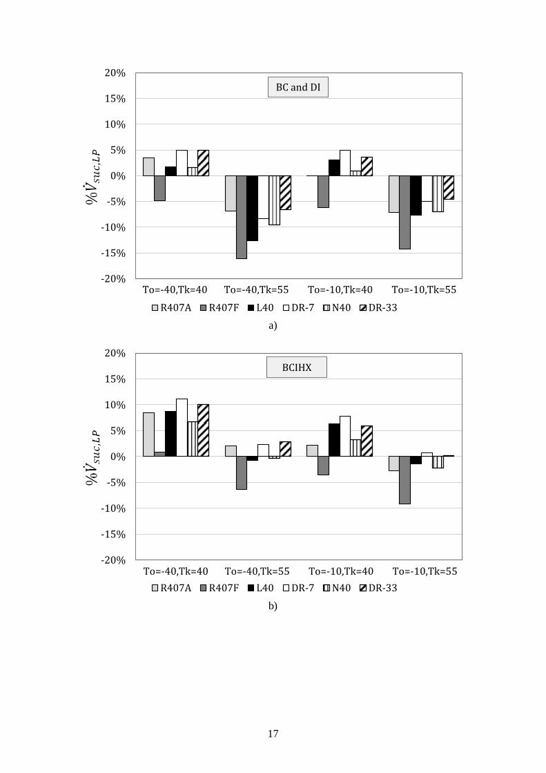
5.1 Volumetric flow rate at low-pressure compressor suction
Fig. 2 presents the results for %�̇�𝑠𝑢𝑐,𝐿𝑃 at two evaporation temperatures, two
condensation temperatures, four different configurations and six refrigerants.
Depending on the conditions and the configuration studied, the results vary widely.
While the lowest differences take place at higher condensation temperatures, the highest
�̇�𝑠𝑢𝑐,𝐿𝑃 relative differences result with DR-7 at low condensation temperatures and with
DR-33 at high condensation temperatures. The refrigerant with the lowest �̇�𝑠𝑢𝑐,𝐿𝑃 values
is R407F for all conditions.
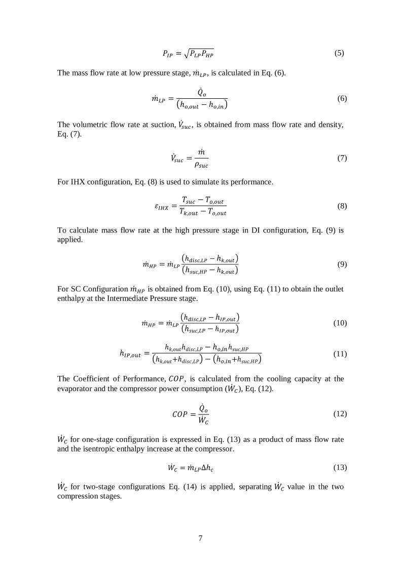
Fig. 2. a) shows %�̇�𝑠𝑢𝑐,𝐿𝑃 for Basic Cycle and Direct Injection configurations. As
�̇�𝑠𝑢𝑐,𝐿𝑃 depends on suction density and low pressure mass flow rate, the same results are
obtained with Basic Cycle configuration and Direct Injection configuration at the low
pressure compressor inlet. Except for R407F, the �̇�𝑠𝑢𝑐,𝐿𝑃 relative difference values are
positive (greater than R404A) at low condensation temperatures.
9
Fig. 2.a) %�̇�𝑠𝑢𝑐 results for BC.
In Fig. 2. b) is represented �̇�𝑠𝑢𝑐,𝐿𝑃 relative differences for Basic Cycle with Internal
Heat Exchanger configuration. �̇�𝑠𝑢𝑐,𝐿𝑃 values of R404A are reduced by the use of the
IHX more than those of alternative fluids. In this way, �̇�𝑠𝑢𝑐,𝐿𝑃 relative differences,
compared to BC and DI configurations, are incremented for all refrigerants. The lowest
values are obtained for R407F at 𝑇𝑜 =-10ºC and 𝑇𝑘 =55ºC instead of 𝑇𝑜 =-40ºC and
𝑇𝑘 =55ºC, as happens for BC. DR-7 and DR-33 have the highest �̇�𝑠𝑢𝑐,𝐿𝑃 relative
differences. The following refrigerants are L40, R407A and N40. The refrigerant with
the lowest values is R407F.
Fig. 2.b) %�̇�𝑠𝑢𝑐 results for BCIHX.
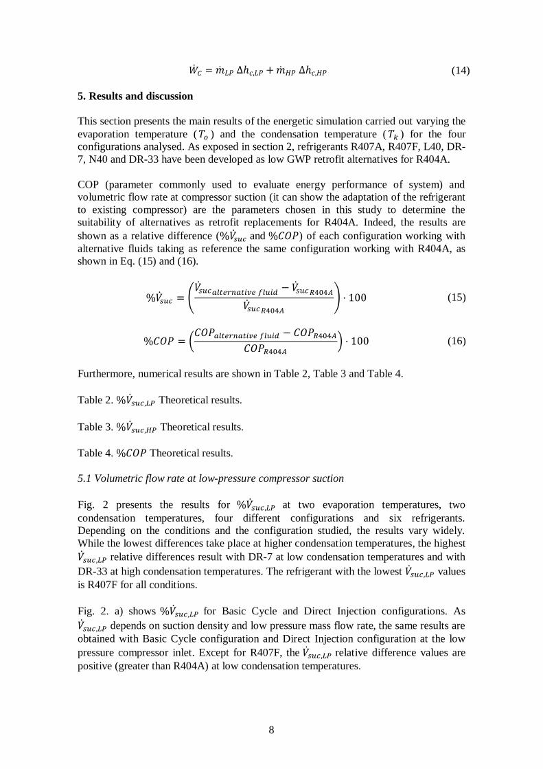
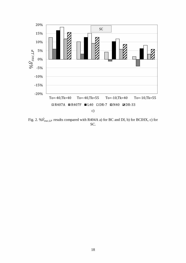
The evolution of �̇�𝑠𝑢𝑐,𝐿𝑃 relative differences for SC is different from the other
configurations, Fig. 2.c). The influence of the condensation temperature is stronger than
the evaporation temperature. The �̇�𝑠𝑢𝑐,𝐿𝑃 relative differences obtained at 𝑇𝑜 =-40ºC,
𝑇𝑘=55ºC are higher than those obtained at 𝑇𝑜=-10ºC, 𝑇𝑘=40ºC. Besides, the results are
in general higher than the other configurations studied, due to the major increase of
mass flow rate for replacements promoted by the subcooler. Refrigerant with the highest
�̇�𝑠𝑢𝑐,𝐿𝑃 relative differences is DR-7, followed by L40.
Fig. 2.c) %�̇�𝑠𝑢𝑐 results for SC.
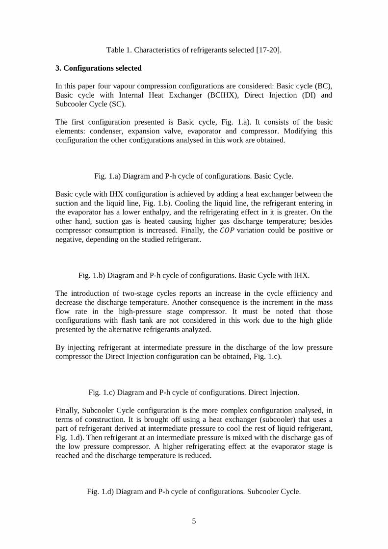
5.2 Volumetric flow rate at high pressure compressor suction
In Fig. 3 are shown the �̇�𝑠𝑢𝑐,𝐻𝑃 relative differences compared with R404A. The highest
relative differences are obtained with DR-7 in all conditions and configurations, and the
lowest with R407F.
For DI configuration, Fig. 3a), all results are negative except DR-7 at 𝑇𝑜 =-40ºC,
𝑇𝑘 =55ºC. The minimum �̇�𝑠𝑢𝑐,𝐻𝑃 values for alternatives results at higher evaporation
temperatures, then with lower condensation temperatures. As said before, the refrigerant
with the highest �̇�𝑠𝑢𝑐,𝐻𝑃 values is R407F, followed by DR-33 and then by N40 and
R407A. The �̇�𝑠𝑢𝑐,𝐻𝑃 relative difference of R407A depends greatly of the conditions
considered.
Fig. 3.a) %�̇�𝑠𝑢𝑐,𝐻𝑃 results compared with R404A for DI.
For SC configuration, Fig. 3b), contrary to what happens in DI most of the �̇�𝑠𝑢𝑐,𝐻𝑃
relative values are positive. Similarly to �̇�𝑠𝑢𝑐,𝐻𝑃 case, the major differences are obtained
at 𝑇𝑜=-40ºC and 𝑇𝑘=40ºC following the same trend in the results.
10
Fig. 3.b) %�̇�𝑠𝑢𝑐,𝐻𝑃 results compared with R404A for SC.
5.3 Coefficient of Performance
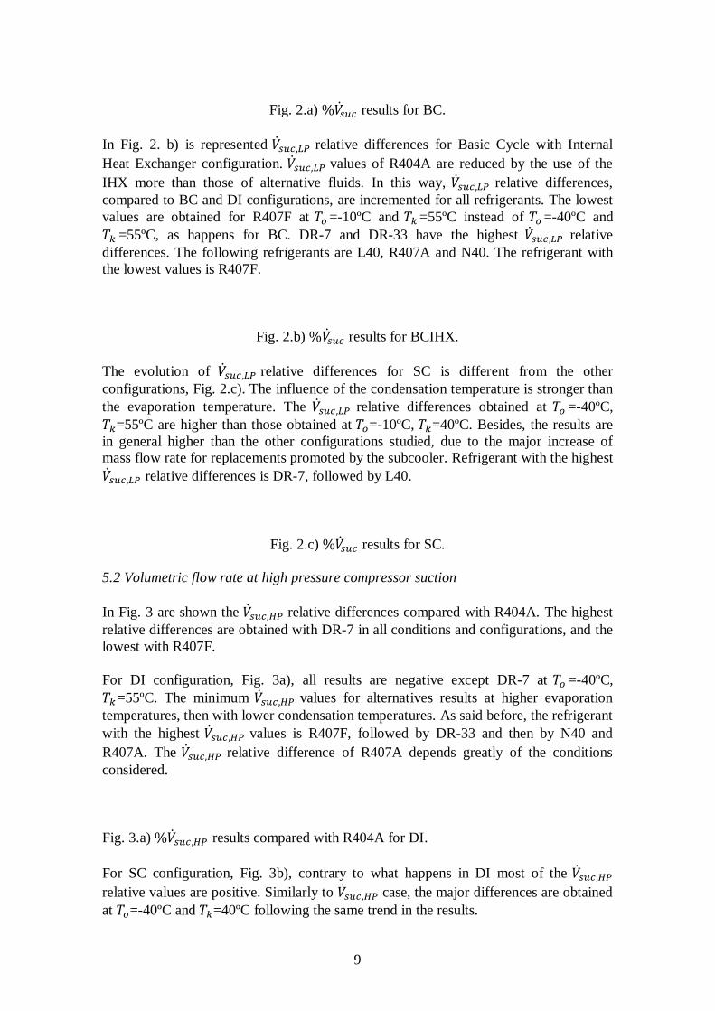
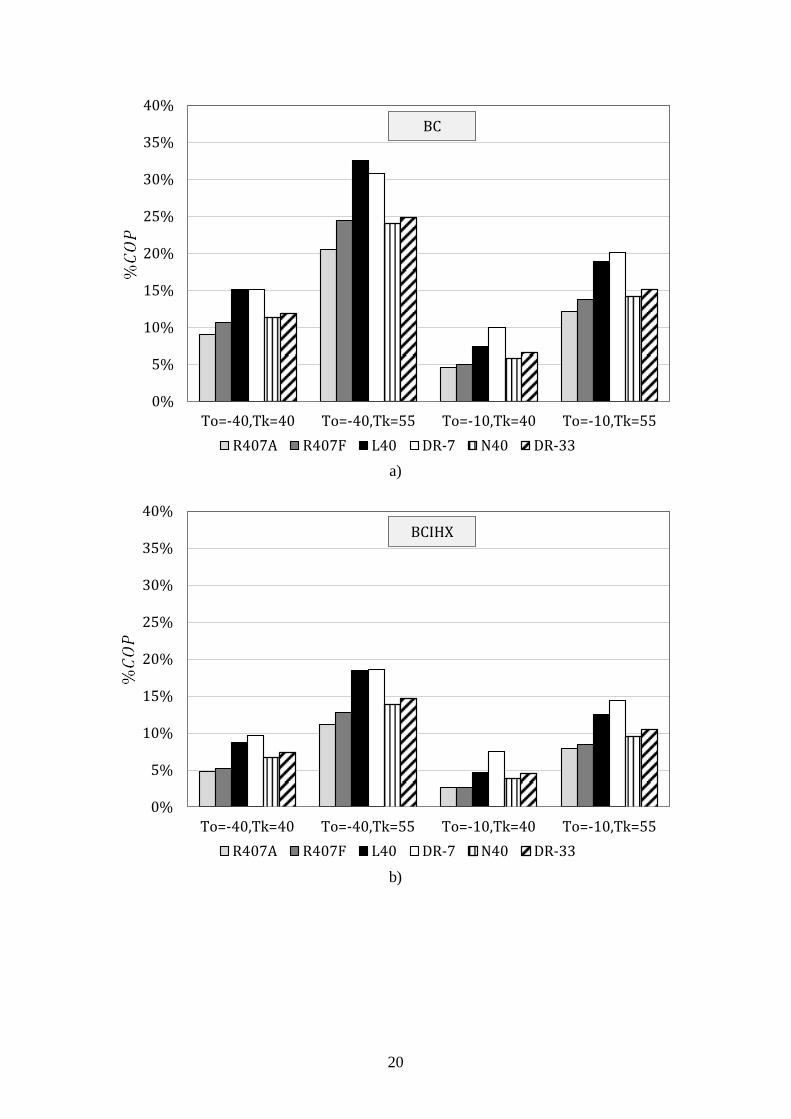
In Fig. 4 %𝐶𝑂𝑃 are shown for the configurations proposed. All differences obtained are
positive, so it can be seen that all refrigerants perform better than R404A. Best results
are obtained with flammable long-term alternatives, then non-flammable long-term
alternatives and finally mid-term refrigerants. Larger differences between replacements
and R404A are obtained at higher compression ratios; this is when higher condensation
temperature and lower evaporation temperature are considered.
As shown in Fig. 4.a), higher %𝐶𝑂𝑃 values are obtained when Basic Cycle
configuration is considered. L40 have higher 𝐶𝑂𝑃 relative differences at lower
compression ratio and DR-7 at higher compression ratio. Next refrigerants in
performance are the non-flammable at long-term, having similar results with a slight
advantage for DR-33. Finally, commercially available refrigerants have lower results,
but R407F is a good alternative in almost in all the cases.
Fig. 4.a) %𝐶𝑂𝑃 results for BC.
Fig. 4.b) shows %𝐶𝑂𝑃 for a Basic cycle with Internal Heat Exchanger configuration
(𝜀𝐼𝐻𝑋=0.3). On the whole, results are closer to R404A than those obtained without IHX,
so it can be deduced that IHX produces more benefices on R404A 𝐶𝑂𝑃 than on its
alternatives. Refrigerant with the highest 𝐶𝑂𝑃 is DR-7. In BC configuration, contrary to
BCIHX case, L40 %𝐶𝑂𝑃 presents higher than DR-7 in some conditions. Non-
flammable long term refrigerants, DR-33 and N40, are affected in the same proportion.
Refrigerants with the lowest values of %𝐶𝑂𝑃 are R407F and R407A.
Fig. 4.b) %𝐶𝑂𝑃 results for BCIHX.
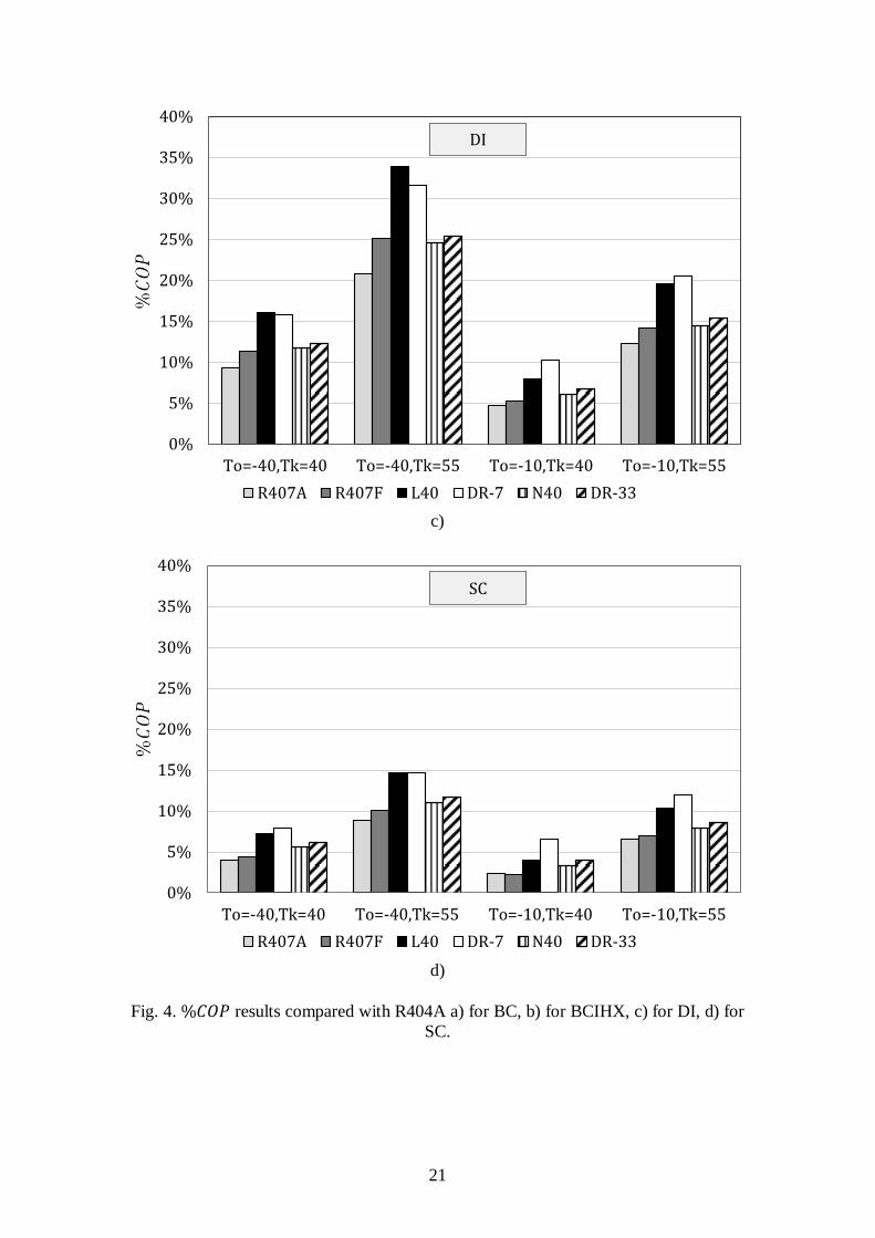
Fig. 4.c), represents 𝐶𝑂𝑃 evaluation for Direct Injection configuration. Results are very
similar to those obtained for Basic cycle. The highest differences results with L40 and
DR-7. The other of refrigerants (the non-flammable alternatives) ranked by 𝐶𝑂𝑃
relative differences are DR-33, N40, R407F and R407A.
Fig. 4.c) %𝐶𝑂𝑃 results for DI.
The results of last case studied, Subcooler Cycle, are presented in Fig. 4.d). As occurs in
the other configurations, flammable refrigerants have the highest %𝐶𝑂𝑃 values. Next
refrigerants in terms of energy performance are the non-flammable options, DR-33 and
N40. The last refrigerants are the mid-term replacements, R407F and R407A. As is the
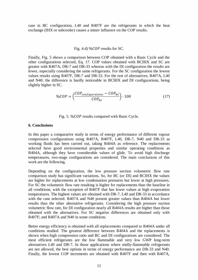
11
case in BC configuration, L40 and R407F are the refrigerants in which the heat
exchange (IHX or subcooler) causes a minor influence on the COP results.
Fig. 4.d) %𝐶𝑂𝑃 results for SC.
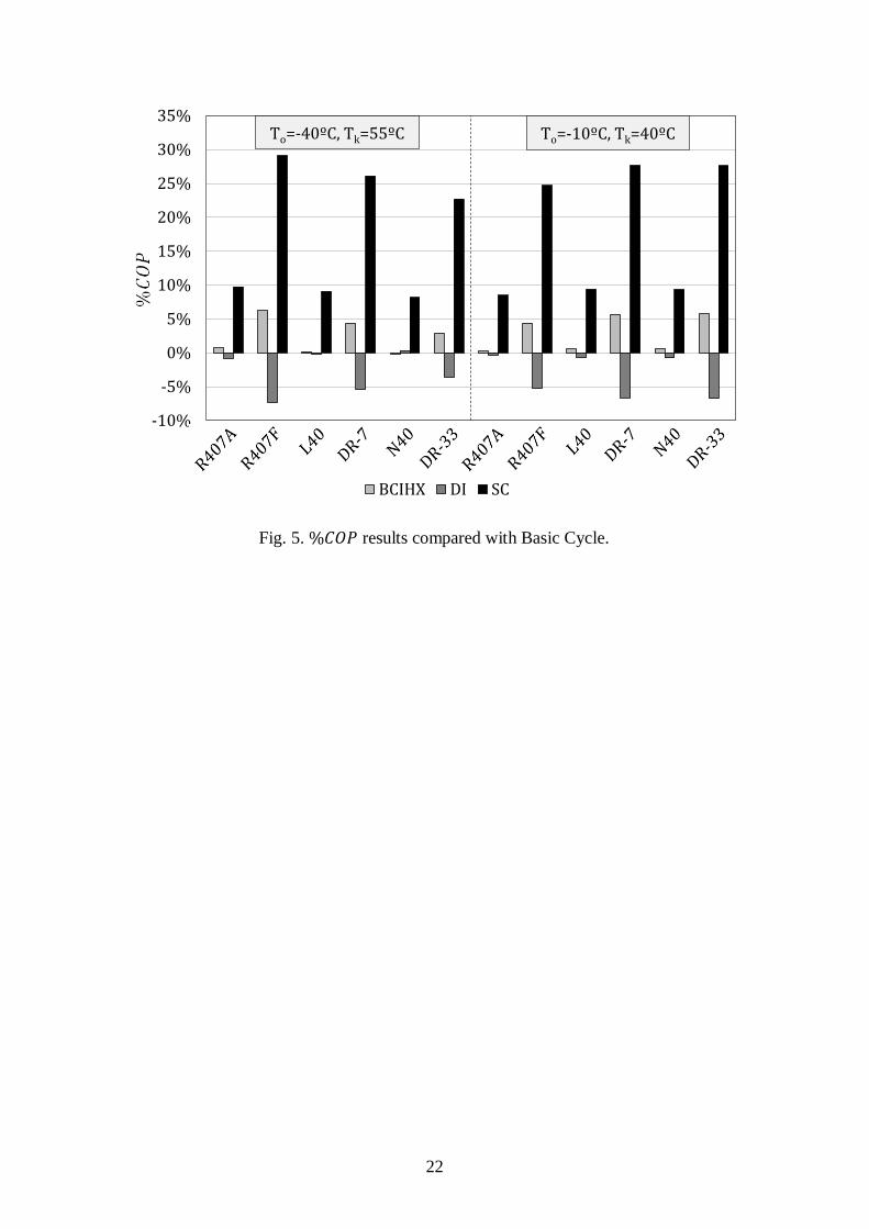
Finally, Fig. 5 shows a comparison between COP obtained with a Basic Cycle and the
other configurations selected, Eq. 17. COP values obtained with BCIHX and SC are
greater with R407A, DR-7 and DR-33 whereas with the DI configuration the results are
lower, especially considering the same refrigerants. For the SC configuration the lowest
values results using R407F, DR-7 and DR-33. For the rest of alternatives; R407A, L40
and N40; the difference is hardly noticeable in BCIHX and DI configurations, being
slightly higher in SC.
%𝐶𝑂𝑃 = (𝐶𝑂𝑃𝑐𝑜𝑛𝑓𝑖𝑔𝑢𝑟𝑎𝑡𝑖𝑜𝑛𝑠 − 𝐶𝑂𝑃𝐵𝐶
𝐶𝑂𝑃𝐵𝐶) · 100 (17)
Fig. 5. %𝐶𝑂𝑃 results compared with Basic Cycle.
6. Conclusions
In this paper a comparative study in terms of energy performance of different vapour
compression configurations using R407A, R407F, L40, DR-7, N40 and DR-33 as
working fluids has been carried out, taking R404A as reference. The replacements
selected have good environmental properties and similar operating conditions as
R404A, although they have considerable values of glide. To avoid high discharge
temperatures, two-stage configurations are considered. The main conclusions of this
work are the following.
Depending on the configuration, the low pressure suction volumetric flow rate
comparison study has significant variations. So, for BC (or DI) and BCIHX the values
are higher for replacements at low condensation pressures but lower at high pressures.
For SC the volumetric flow rate resulting is higher for replacements than the baseline in
all conditions, with the exception of R407F that has lower values at high evaporation
temperatures. The highest values are obtained with DR-7, L40 and DR-33 in accordance
with the case selected. R407A and N40 present greater values than R404A but lower
results than the other alternative refrigerants. Considering the high pressure suction
volumetric flow rate, for DI configuration nearly all R404A results are higher than those
obtained with the alternatives. For SC negative differences are obtained only with
R407F; and R407A and N40 in some conditions.
Better energy efficiency is obtained with all replacements compared to R404A under all
conditions studied. The greatest difference between R404A and the replacements is
shown when high compression ratio and BC and DI configurations are considered. The
most efficient refrigerants are the low flammable and very low GWP long-term
alternatives L40 and DR-7. In those applications where midly-flammable refrigerants
are not allowed, the best options in terms of energy performance are DR-33 and N40.
Finally, the lowest COP increments are obtained with R407F and then with R407A,
12
even though those are still promising values. Those refrigerants have the advantage that
they are commercially available and their discharge temperatures are the lowest among
all replacement refrigerants.
Acknowledgements
The authors thankfully acknowledge “Ministerio de Educación, Cultura y Deporte” for
supporting this work through “Becas y Contratos de Formación de Profesorado
Universitario del Programa Nacional de Formación de Recursos Humanos de
Investigación del ejercicio 2012” The authors also want to acknowledge Honeywell
International Inc. for supporting this work.
References
[1] UNEP. Decisions adopted by the nineteenth meeting of the parties to the
Montreal Protocol on substances that deplete the ozone layer. Nairobi, Kenya:
United Nations Environment Programme (UNEP) Ozone Secretariat; 2007.
[2] J.M. Calm. The next generation of refrigerants – Historical review, considerations, and outlook. International Journal of Refrigeration 31 (2008), 1123-1133.
[3] Kyoto Protocol, Report of the Conference of the Parties, United Nations
Framework Convention on Climate Change (UNFCCC), 1997.
[4] Directive 2006/40/EC of The European Parliament and of the Council of 17
May 2006 relating to emissions from air conditioning systems in motor vehicles
and amending Council Directive 70/156/EC. Official Journal of the European
Union.
[5] Ley 16/2013, de 29 de octubre, por la que se establecen determinadas medidas
en materia de fiscalidad medioambiental y se adoptan otras medidas tributarias y
financieras. Boletín Oficial del Estado.
[6] D. Cowan, J. Gartshore, I. Chaer, C. Francis, G. Maidment. REAL Zero – Reducing refrigerant emissions & leakage - feedback from the IOR Project. Institute of Refrigeration, 22 April 2010.
[7] U.S. Environmental Protection Agency. Transitioning to Low GWP Alternatives
in Commercial Refrigeration, 2010. Retrieved online at:
http://www.epa.gov/ozone/downloads/EPA_HFC_ComRef.pdf , 3 September
2013.
[8] M. Mohanraj, S. Jayaraj, C. Muraleedharan. Environment friendly alternatives to halogenated refrigerants—A review. International Journal of Greenhouse gas control 3 (2009), 108-119.
[9] Z. Yang, X. Wu. Retrofits and options for the alternatives to HCFC-22. Energy
59 (2013), 1-21.
[10] M. W. Spatz, S. F. Yana Motta. An evaluation of options for replacing HCFC-22 in medium temperature refrigeration systems. International Journal of Refrigeration 27 (2004), 475–483.
[11] R. Llopis, E. Torrella, R. Cabello, D. Sánchez. Performance evaluation of R404A and R507A refrigerant mixtures in an experimental double-stage vapour compression plant. Applied Energy 87 (2010) 1546–1553.
13
[12] Y.T. Ge, R. Cropper. Performance simulation of refrigerated display cabinets operating with refrigerants R22 and R404A. Applied Energy 85 (2008), 694–707.
[13] A. Arora, S.C. Kaushik. Theoretical analysis of a vapour compression refrigeration system with R502, R404A and R507A. International Journal of Refrigeration 31 (2008), 998-1005.
[14] Y. Ge, R. Cropper. Air-cooled condensers in retail systems using R22 and R404A refrigerants. Applied Energy 78 (2004), 95–110.
[15] IPPC, Climate change 2001—the scientific basis, intergovernmental panel on climate change. Cambridge: Cambridge University Press, 2001.
[16] H. Jürgensen. Refrigerants in Future and in Legislation 2013. In Stockholm,
Sweden, 10 April 2013.
[17] Linde Gases Division. R407A. Lower Global Warming Potential replacement
for R404A. Retrieved online at: http://www.linde-
gas.com/internet.global.lindegas.global/en/images/BAMPG_Refrigerants_407A
_fin17_92206.pdf, 5 September 2013.
[18] Linde Gases Division. R407F – Genetron® Performax™ LT. Lower Global Warming Potential replacement for R404A. Retrieved online at: http://www.linde-gas.com/internet.global.lindegas.global/en/images/BAMPG_Refrigerants_407F_fin17_92205.pdf, 5 September 2013.
[19] Honeywell International Inc. Honeywell Solstice™ N40 Refrigerant Improved Energy Efficiency Case Study, Gaining Competitive Advantage through Improved Energy Efficiency and Reduced Environmental Impact - September 2012. Retrieved online at: http://www.honeywell-refrigerants.com/india/resources/customer-case-studies/honeywell-solstice-n40-improved-energy-efficiency-case-study/, 3 September 2013.
[20] B.H. Minor, F. Rinne. Low GWP R-404A Alternatives for Commercial Refrigeration. ASHRAE Transactions 118(1), Chicago, IL, 9-11 October 2012.
[21] American Society of Heating, Refrigerating and Air-Conditioning Engineers. ASHRAE, Standard 34 Designation and Safety Classification of Refrigerants, 2010.
[22] S. F. Yana Motta, E. V. Becerra, M. W. Spatz. Low Global Warming
Refrigerants For Commercial Refrigeration Systems. In: International
Refrigeration and Air Conditioning Conference, 2012. Paper 1351.
[23] N.Q. Minh, N.J Hewitt, P.C. Eames. Improved Vapour Compression Refrigeration Cycles: Literature Review and Their Application to Heat Pumps. In: International Refrigeration and Air Conditioning Conference, 2006. Paper 795.
[24] P.A. Domanski, D.A. Didion, J.P. Doyle. Evaluation of Suction-line/Liquid-line Heat Exchange in the Refrigeration cycle. International Journal of Refrigeration 17 (1994), 487-493.
[25] K. Sumeru, H. Nasution, F.N. Ani, A review on two-phase ejector as an expansion device in vapor compression refrigeration cycle, Renewable and Sustainable Energy Reviews 16 (2012), 4927 – 4937.
14
[26] A. Subiantoro, K.T. Ooi, Economic analysis of the application of expanders in medium scale air-conditioners with conventional refrigerants, R1234yf and CO2, International Journal of Refrigeration 36 (2013), 1472 – 1482.
[27] E. Torrella, J.A. Larumbe, R. Cabello, R. Llopis, D. Sanchez. A general methodology for energy comparison of intermediate configurations in two-stage vapour compression refrigeration systems. Energy 36 (2012), 4119-4124.
[28] F. Memet, D.E. Mitu. First Law Analysis of a Two-stage Ejector-vapor Compression Refrigeration Cycle working with R404A. Analele Universitatii "Eftimie Murgu" Resita 18 (2011), 151-156.
[29] Honeywell. Technology issues regarding Blends of Refrigerants 2012. Retrieved online at: http://www.honeywell-refrigerants.com/europe/?document=honeywell-blends-technology-issues-2012-presentation&download=1, 1 October 2013.
[30] E.W. Lemmon, M.L. Huber, M.O. McLinden, REFPROP, NIST Standard
Reference Database 23, v.8, National Institute of Standards, Gaithersburg, MD,
USA, 2007.
[31] K. Baumann, E. Blass. Beitrag zur Ermittlung des Optimalen Mitteldruckes bei
zweistufigen Kaltdampf Verdichter-Kältemaschinen. Kältetechnik, 1961, vol. 13
p. 210-216.
15
a)
b)
3
200 250 300 350 400 450
Pre
ssu
re
Enthalpy
1
3
4
2
4 1
23
CONDENSER
EVAPORATOR
COMP.TXV
3’
14
23
1’
IHX
3
200 300 400 500
Pre
ssu
re
Enthalpy
1'1
3' 23
4
16
c)
d)
Fig. 1. Diagram and P-h cycle of configurations a) Basic Cycle, b) Basic Cycle with
IHX, c) Direct Injection, d) Subcooler Cycle.
HP STAGE
LP STAGE
1
23
4
B A
C
3
200 250 300 350 400 450
Pre
ssu
re
Enthalpy
3 2
1
BA
4
HP STAGE
LP STAGE
C
1
23
A
SUBCOOLER
HP STAGE
LP STAGE
4
B
3’
B’
C
3
200 250 300 350 400 450
Pre
ssu
re
Enthalpy
LP STAGE
HP STAGE
1
A
233'
BC
4
B'
17
a)
b)
-20%
-15%
-10%
-5%
0%
5%
10%
15%
20%
R407A R407F L40 DR-7 N40 DR-33
BC and DI
To=-40,Tk=40 To=-40,Tk=55 To=-10,Tk=40 To=-10,Tk=55
-20%
-15%
-10%
-5%
0%
5%
10%
15%
20%
R407A R407F L40 DR-7 N40 DR-33
BCIHX
To=-40,Tk=40 To=-40,Tk=55 To=-10,Tk=40 To=-10,Tk=55
18
c)
Fig. 2. %�̇�𝑠𝑢𝑐,𝐿𝑃 results compared with R404A a) for BC and DI, b) for BCIHX, c) for
SC.
-20%
-15%
-10%
-5%
0%
5%
10%
15%
20%
R407A R407F L40 DR-7 N40 DR-33
SC
To=-40,Tk=40 To=-40,Tk=55 To=-10,Tk=40 To=-10,Tk=55

19
a)
b)
Fig. 3. %�̇�𝑠𝑢𝑐,𝐻𝑃 results compared with R404A a) for DI, b) for SC.
-25%
-20%
-15%
-10%
-5%
0%
5%
10%
15%
20%
R407A R407F L40 DR-7 N40 DR-33
DI
To=-40,Tk=40 To=-40,Tk=55 To=-10,Tk=40 To=-10,Tk=55
-25%
-20%
-15%
-10%
-5%
0%
5%
10%
15%
20%
R407A R407F L40 DR-7 N40 DR-33
SC
To=-40,Tk=40 To=-40,Tk=55 To=-10,Tk=40 To=-10,Tk=55
20
a)
b)
0%
5%
10%
15%
20%
25%
30%
35%
40%
To=-40,Tk=40 To=-40,Tk=55 To=-10,Tk=40 To=-10,Tk=55
R407A R407F L40 DR-7 N40 DR-33
BC
0%
5%
10%
15%
20%
25%
30%
35%
40%
To=-40,Tk=40 To=-40,Tk=55 To=-10,Tk=40 To=-10,Tk=55
R407A R407F L40 DR-7 N40 DR-33
BCIHX
21
c)
d)
Fig. 4. %𝐶𝑂𝑃 results compared with R404A a) for BC, b) for BCIHX, c) for DI, d) for
SC.
0%
5%
10%
15%
20%
25%
30%
35%
40%
To=-40,Tk=40 To=-40,Tk=55 To=-10,Tk=40 To=-10,Tk=55
R407A R407F L40 DR-7 N40 DR-33
DI
0%
5%
10%
15%
20%
25%
30%
35%
40%
To=-40,Tk=40 To=-40,Tk=55 To=-10,Tk=40 To=-10,Tk=55
R407A R407F L40 DR-7 N40 DR-33
SC
22
Fig. 5. %𝐶𝑂𝑃 results compared with Basic Cycle.
-10%
-5%
0%
5%
10%
15%
20%
25%
30%
35%
BCIHX DI SC
To=-40ºC, Tk=55ºC To=-10ºC, Tk=40ºC
23
FIGURE CAPTIONS
Fig. 1. Diagram and P-h cycle of configurations a) Basic Cycle, b) Basic Cycle with
IHX, c) Direct Injection, d) Subcooler Cycle.
Fig. 2. %�̇�𝑠𝑢𝑐,𝐿𝑃 results compared with R404A a) for BC and DI, b) for BCIHX, c) for
SC.
Fig. 3. %�̇�𝑠𝑢𝑐,𝐻𝑃 results compared with R404A a) for DI, b) for SC.
Fig. 4. %𝐶𝑂𝑃 results compared with R404A a) for BC, b) for BCIHX, c) for DI, d) for
SC.
Fig. 5. %𝐶𝑂𝑃 results compared with Basic Cycle.
24
Table 1. Characteristics of refrigerants selected [17-20].
ASHRAE
safety class.
Boiling
Point** Critical T Critical P Glide
b ODP
100-yr
GWP
R404A A1 -46.5 ºC 72.0 ºC 37.3bar 0.8 ºC 0 3922
R407A A1 -45.3 ºC 82.3 ºC 45.0 bar 6.4 ºC 0 2017
R407F A1 -46.3 ºC 82.7 ºC 47.5 bar 6.4 ºC 0 1824
L40 A2L a -44.7 ºC 86.8 ºC 47.3 bar 7.7 ºC 0 285
DR-7 A2L a -43.3 ºC 69.1 ºC 45.5 bar 5.0 ºC 0 246
N40 A1 a -45.1 ºC 83.2 ºC 44.5 bar 6.1 ºC 0 1205
DR-33 A1 a -44.3 ºC 83.1 ºC 43.1 bar 6.0 ºC 0 1410
a estimated safety group rating
b pressure = 1bar
25
Table 2. %�̇�𝑠𝑢𝑐,𝐿𝑃 Theoretical results.
𝑻𝒐=-40ºC 𝑻𝒐=-10ºC
𝑻𝒌=40ºC 𝑻𝒌=55ºC 𝑻𝒌=40ºC 𝑻𝒌=55ºC
BC
R407A 3.52% -6.82% -0.07% -7.18%
R407F -4.88% -16.18% -6.23% -14.19%
L40 1.78% -12.61% 3.04% -7.72%
DR-7 5.02% -8.39% 4.95% -4.94%
N40 1.54% -9.48% 0.90% -6.97%
DR-33 4.90% -6.54% 3.56% -4.61%
BCIHX
R407A 8.44% 2.05% 2.14% -2.74%
R407F 0.85% -6.29% -3.58% -9.09%
L40 8.80% -0.77% 6.38% -1.34%
DR-7 11.16% 2.33% 7.82% 0.71%
N40 6.67% -0.29% 3.29% -2.21%
DR-33 10.12% 2.86% 5.96% 0.23%
SC
R407A 12.65% 10.15% 4.14% 1.63%
R407F 5.98% 3.11% -1.16% -4.05%
L40 16.68% 12.79% 10.28% 6.25%
DR-7 18.56% 15.12% 11.76% 8.18%
N40 11.85% 9.15% 5.80% 3.00%
DR-33 15.58% 12.78% 8.68% 5.78%
26
Table 3. %�̇�𝑠𝑢𝑐,𝐻𝑃 Theoretical results.
𝑻𝒐=-40ºC 𝑻𝒐=-10ºC
𝑻𝒌=40ºC 𝑻𝒌=55ºC 𝑻𝒌=40ºC 𝑻𝒌=55ºC
DI
R407A -6.04% -4.96% -15.80% -11.94%
R407F -13.50% -10.81% -24.09% -18.56%
L40 -6.67% -1.91% -20.14% -12.21%
DR-7 -1.07% 2.47% -13.95% -7.21%
N40 -6.00% -3.30% -16.49% -10.97%
DR-33 3.60% 1.43% 0.82% -1.34%
SC
R407A 2.29% -0.92% -0.35% -3.50%
R407F -3.57% -5.96% -6.49% -8.86%
L40 7.06% 5.03% 3.25% 1.19%
DR-7 11.74% 9.17% 8.30% 5.70%
N40 -3.06% -0.63% -13.96% -8.62%
DR-33 6.86% 4.32% 3.96% 1.43%

27
Table 4. %𝐶𝑂𝑃 Theoretical results.
𝑻𝒐=-40ºC 𝑻𝒐=-10ºC
𝑻𝒌=40ºC 𝑻𝒌=55ºC 𝑻𝒌=40ºC 𝑻𝒌=55ºC
BC
R407A 9.02% 20.52% 4.53% 12.14%
R407F 10.62% 24.45% 4.93% 13.83%
L40 15.07% 32.60% 7.45% 18.92%
DR-7 15.09% 30.76% 9.94% 20.13%
N40 11.31% 24.05% 5.79% 14.18%
DR-33 11.87% 24.78% 6.56% 15.09%
BCIHX
R407A 4.80% 11.20% 2.68% 7.84%
R407F 5.25% 12.82% 2.58% 8.48%
L40 8.69% 18.50% 4.70% 12.47%
DR-7 9.65% 18.55% 7.56% 14.46%
N40 6.71% 13.83% 3.79% 9.49%
DR-33 7.32% 14.60% 4.59% 10.42%
DI
R407A 9.36% 20.84% 4.72% 12.30%
R407F 11.27% 25.10% 5.31% 14.17%
L40 16.08% 33.91% 8.01% 19.57%
DR-7 15.74% 31.67% 10.28% 20.55%
N40 11.75% 24.57% 6.02% 14.41%
DR-33 12.29% 25.31% 6.77% 15.33%
SC
R407A 4.01% 8.91% 2.31% 6.52%
R407F 4.42% 10.12% 2.25% 7.01%
L40 7.23% 14.70% 4.01% 10.31%
DR-7 7.87% 14.61% 6.50% 11.97%
N40 5.58% 11.02% 3.25% 7.87%
DR-33 6.08% 11.64% 3.94% 8.65%


![[Nome completo do autor] for masonry consolidation · [Nome completo do autor] [Nome completo do autor] [Nome completo do autor] [Nome completo do autor] [Nome completo do autor]](https://img.pdfslide.us/doc/110x75/5be3896c09d3f2f02d8d137b/nome-completo-do-autor-for-masonry-consolidation-nome-completo-do-autor.jpg)