Embed Size (px)
Citation preview
36
FOR HELP OR ADVICE ON THIS PRODUCT PLEASE CONTACT YOUR DISTRIBUTOR,
OR SIP DIRECTLY ON:
TEL: 01509500400
EMAIL: [email protected] or [email protected]
www.sip-group.com
Ref: 031215
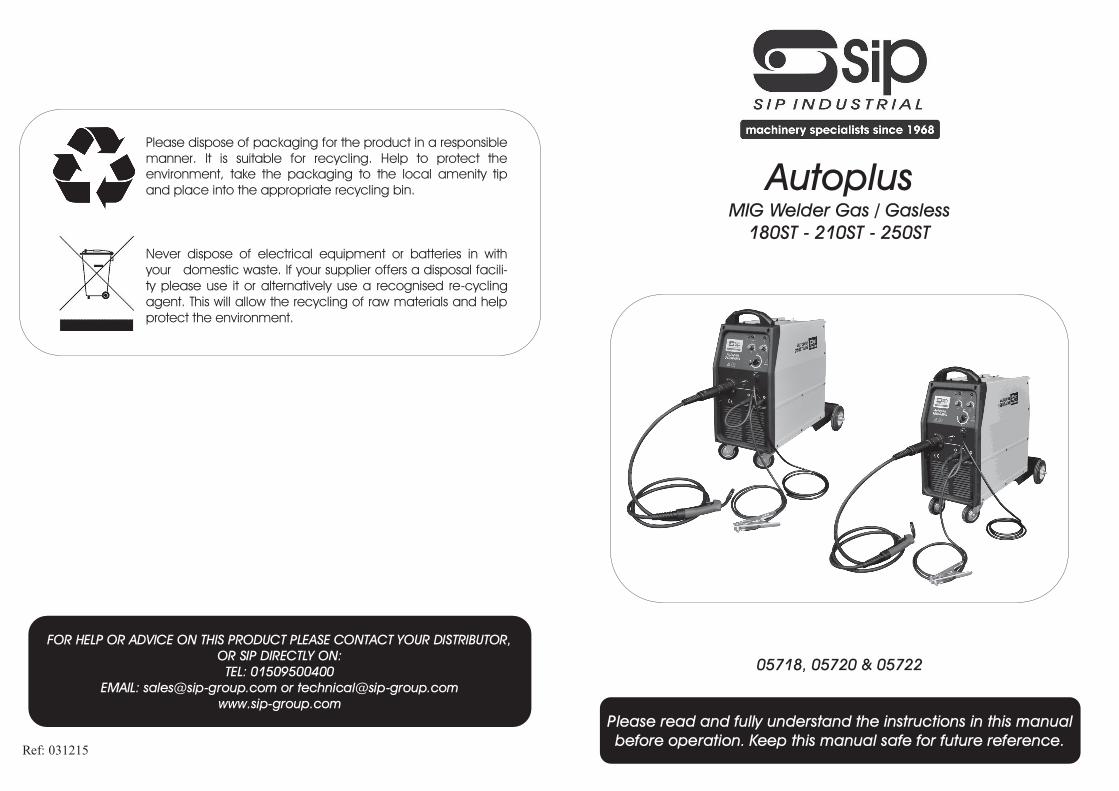
Please dispose of packaging for the product in a responsible
manner. It is suitable for recycling. Help to protect the
environment, take the packaging to the local amenity tip
and place into the appropriate recycling bin.
Never dispose of electrical equipment or batteries in with
your domestic waste. If your supplier offers a disposal facili-
ty please use it or alternatively use a recognised re-cycling
agent. This will allow the recycling of raw materials and help
protect the environment.
1
Please read and fully understand the instructions in this manual
before operation. Keep this manual safe for future reference.
05718, 05720 & 05722
Autoplus
MIG Welder Gas / Gasless
180ST - 210ST - 250ST
2
35
Declaration of Conformity
We
SIP (Industrial Products) Ltd Gelders Hall Road
Shepshed
Loughborough
Leicestershire
LE12 9NH
England
As the manufacturer's authorised representative within the EC
declare that the
Autoplus 180ST Mig Welder - SIP Part. No. 05718
Autoplus 210ST Mig Welder - SIP Part. No. 05720
Autoplus 250ST Mig Welder - SIP Part No. 05722
Conforms to the requirements of the following directive(s), as indicated.
2006/95/EC Low Voltage Directive
2004/108/EC EMC Directive
2008/35/EC RoHS Directive
Signed: …………………………………...
Mr P. Ippaso - Managing Director - SIP (Industrial Products) Ltd
Date: 02/06/2015.
And the relevant harmonised standard(s), including
DECLARATION OF CONFORMITY
EN 60974-1:2012 EN 60974-10:2007
34
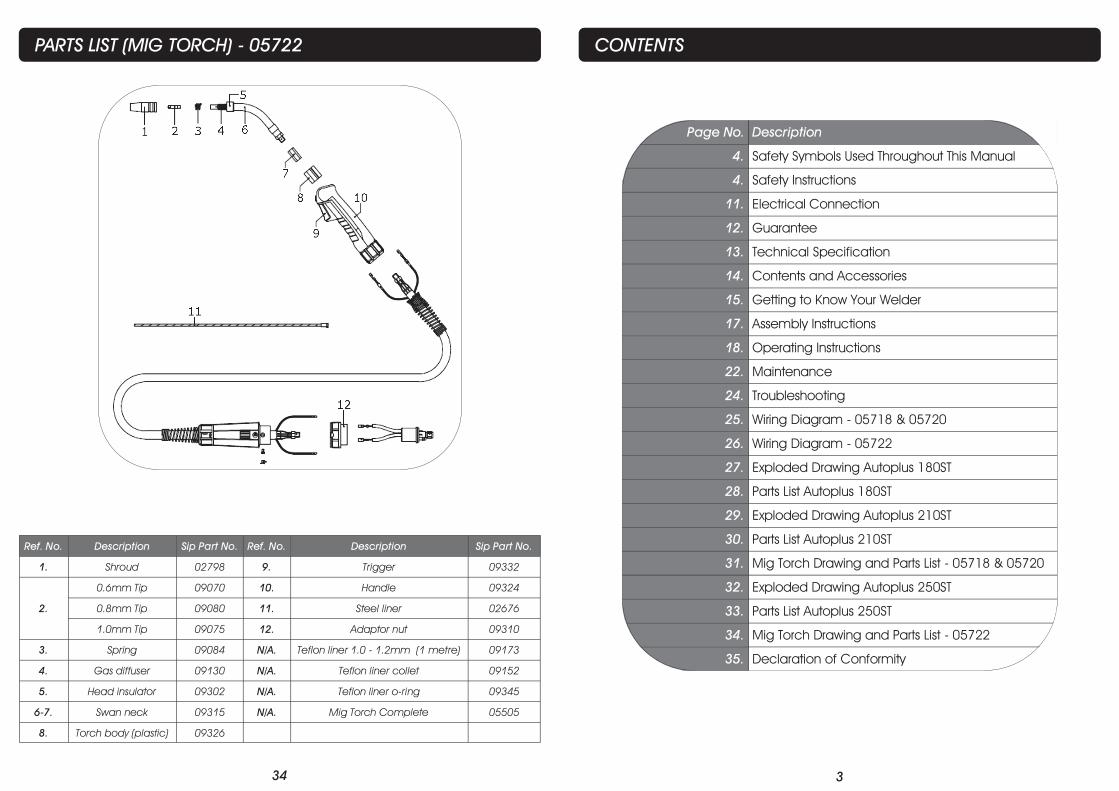
PARTS LIST (MIG TORCH) - 05722
Ref. No. Description Sip Part No. Ref. No. Description Sip Part No.
1. Shroud 02798 9. Trigger 09332
0.6mm Tip 09070 10. Handle 09324
2. 0.8mm Tip 09080 11. Steel liner 02676
1.0mm Tip 09075 12. Adaptor nut 09310
3. Spring 09084 N/A. Teflon liner 1.0 - 1.2mm (1 metre) 09173
4. Gas diffuser 09130 N/A. Teflon liner collet 09152
5. Head insulator 09302 N/A. Teflon liner o-ring 09345
6-7. Swan neck 09315 N/A. Mig Torch Complete 05505
8. Torch body (plastic) 09326
3
CONTENTS
Page No. Description
4. Safety Symbols Used Throughout This Manual
4. Safety Instructions
11. Electrical Connection
12. Guarantee
13. Technical Specification
14. Contents and Accessories
15. Getting to Know Your Welder
17. Assembly Instructions
18. Operating Instructions
22. Maintenance
24. Troubleshooting
25. Wiring Diagram - 05718 & 05720
26. Wiring Diagram - 05722
27. Exploded Drawing Autoplus 180ST
28. Parts List Autoplus 180ST
29. Exploded Drawing Autoplus 210ST
30. Parts List Autoplus 210ST
31. Mig Torch Drawing and Parts List - 05718 & 05720
32. Exploded Drawing Autoplus 250ST
33. Parts List Autoplus 250ST
34. Mig Torch Drawing and Parts List - 05722
35. Declaration of Conformity
4
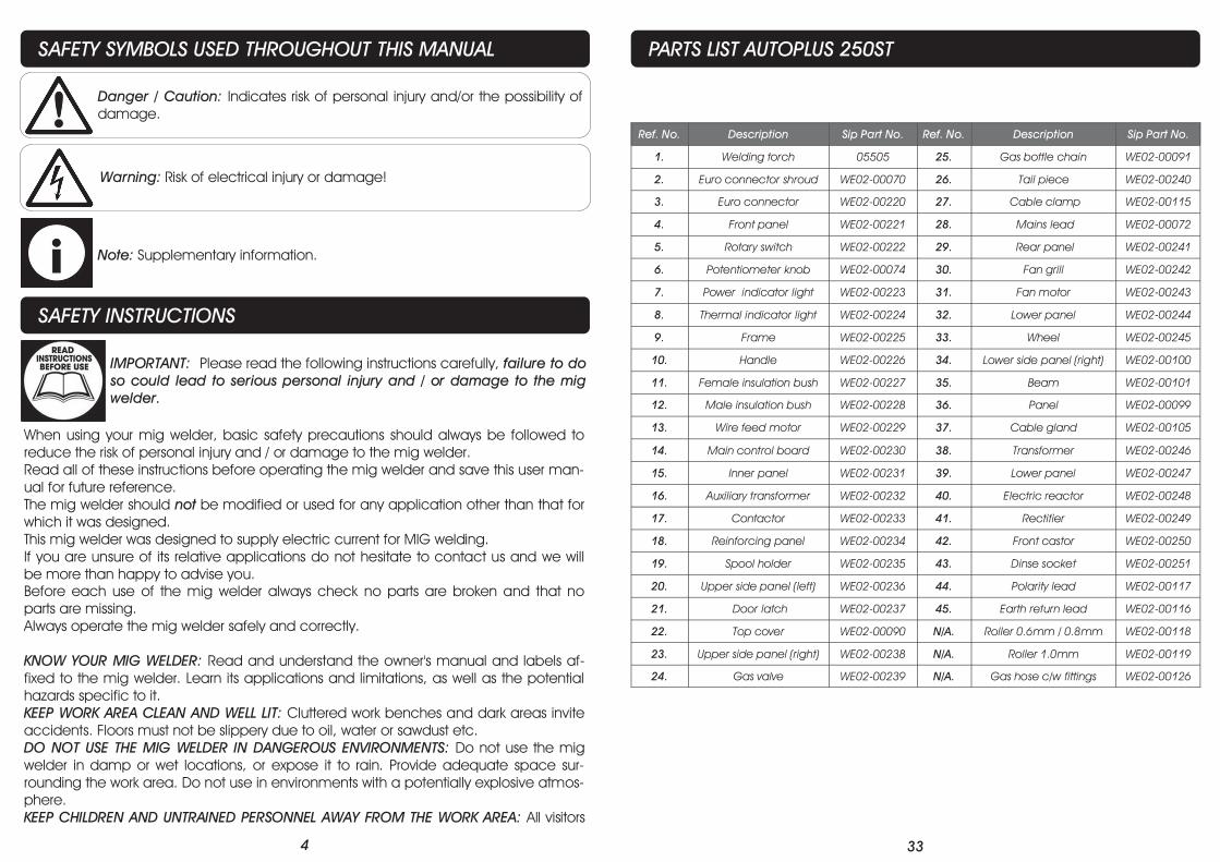
SAFETY SYMBOLS USED THROUGHOUT THIS MANUAL
SAFETY INSTRUCTIONS
IMPORTANT: Please read the following instructions carefully, failure to do
so could lead to serious personal injury and / or damage to the mig
welder.
Danger / Caution: Indicates risk of personal injury and/or the possibility of
damage.
Warning: Risk of electrical injury or damage!
Note: Supplementary information.
When using your mig welder, basic safety precautions should always be followed to
reduce the risk of personal injury and / or damage to the mig welder.
Read all of these instructions before operating the mig welder and save this user man-
ual for future reference.
The mig welder should not be modified or used for any application other than that for
which it was designed.
This mig welder was designed to supply electric current for MIG welding.
If you are unsure of its relative applications do not hesitate to contact us and we will
be more than happy to advise you.
Before each use of the mig welder always check no parts are broken and that no
parts are missing.
Always operate the mig welder safely and correctly.
KNOW YOUR MIG WELDER: Read and understand the owner's manual and labels af-
fixed to the mig welder. Learn its applications and limitations, as well as the potential
hazards specific to it.
KEEP WORK AREA CLEAN AND WELL LIT: Cluttered work benches and dark areas invite
accidents. Floors must not be slippery due to oil, water or sawdust etc.
DO NOT USE THE MIG WELDER IN DANGEROUS ENVIRONMENTS: Do not use the mig
welder in damp or wet locations, or expose it to rain. Provide adequate space sur-
rounding the work area. Do not use in environments with a potentially explosive atmos-
phere.
KEEP CHILDREN AND UNTRAINED PERSONNEL AWAY FROM THE WORK AREA: All visitors
33
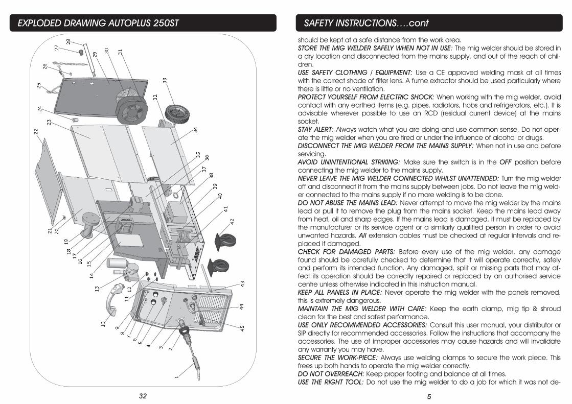
PARTS LIST AUTOPLUS 250ST
Ref. No. Description Sip Part No. Ref. No. Description Sip Part No.
1. Welding torch 05505 25. Gas bottle chain WE02-00091
2. Euro connector shroud WE02-00070 26. Tail piece WE02-00240
3. Euro connector WE02-00220 27. Cable clamp WE02-00115
4. Front panel WE02-00221 28. Mains lead WE02-00072
5. Rotary switch WE02-00222 29. Rear panel WE02-00241
6. Potentiometer knob WE02-00074 30. Fan grill WE02-00242
7. Power indicator light WE02-00223 31. Fan motor WE02-00243
8. Thermal indicator light WE02-00224 32. Lower panel WE02-00244
9. Frame WE02-00225 33. Wheel WE02-00245
10. Handle WE02-00226 34. Lower side panel (right) WE02-00100
11. Female insulation bush WE02-00227 35. Beam WE02-00101
12. Male insulation bush WE02-00228 36. Panel WE02-00099
13. Wire feed motor WE02-00229 37. Cable gland WE02-00105
14. Main control board WE02-00230 38. Transformer WE02-00246
15. Inner panel WE02-00231 39. Lower panel WE02-00247
16. Auxiliary transformer WE02-00232 40. Electric reactor WE02-00248
17. Contactor WE02-00233 41. Rectifier WE02-00249
18. Reinforcing panel WE02-00234 42. Front castor WE02-00250
19. Spool holder WE02-00235 43. Dinse socket WE02-00251
20. Upper side panel (left) WE02-00236 44. Polarity lead WE02-00117
21. Door latch WE02-00237 45. Earth return lead WE02-00116
22. Top cover WE02-00090 N/A. Roller 0.6mm / 0.8mm WE02-00118
23. Upper side panel (right) WE02-00238 N/A. Roller 1.0mm WE02-00119
24. Gas valve WE02-00239 N/A. Gas hose c/w fittings WE02-00126
32
EXPLODED DRAWING AUTOPLUS 250ST
5
SAFETY INSTRUCTIONS….cont
should be kept at a safe distance from the work area.
STORE THE MIG WELDER SAFELY WHEN NOT IN USE: The mig welder should be stored in
a dry location and disconnected from the mains supply, and out of the reach of chil-
dren.
USE SAFETY CLOTHING / EQUIPMENT: Use a CE approved welding mask at all times
with the correct shade of filter lens. A fume extractor should be used particularly where
there is little or no ventilation.
PROTECT YOURSELF FROM ELECTRIC SHOCK: When working with the mig welder, avoid
contact with any earthed items (e.g. pipes, radiators, hobs and refrigerators, etc.). It is
advisable wherever possible to use an RCD (residual current device) at the mains
socket.
STAY ALERT: Always watch what you are doing and use common sense. Do not oper-
ate the mig welder when you are tired or under the influence of alcohol or drugs.
DISCONNECT THE MIG WELDER FROM THE MAINS SUPPLY: When not in use and before
servicing.
AVOID UNINTENTIONAL STRIKING: Make sure the switch is in the OFF position before
connecting the mig welder to the mains supply.
NEVER LEAVE THE MIG WELDER CONNECTED WHILST UNATTENDED: Turn the mig welder
off and disconnect it from the mains supply between jobs. Do not leave the mig weld-
er connected to the mains supply if no more welding is to be done.
DO NOT ABUSE THE MAINS LEAD: Never attempt to move the mig welder by the mains
lead or pull it to remove the plug from the mains socket. Keep the mains lead away
from heat, oil and sharp edges. If the mains lead is damaged, it must be replaced by
the manufacturer or its service agent or a similarly qualified person in order to avoid
unwanted hazards. All extension cables must be checked at regular intervals and re-
placed if damaged.
CHECK FOR DAMAGED PARTS: Before every use of the mig welder, any damage
found should be carefully checked to determine that it will operate correctly, safely
and perform its intended function. Any damaged, split or missing parts that may af-
fect its operation should be correctly repaired or replaced by an authorised service
centre unless otherwise indicated in this instruction manual.
KEEP ALL PANELS IN PLACE: Never operate the mig welder with the panels removed,
this is extremely dangerous.
MAINTAIN THE MIG WELDER WITH CARE: Keep the earth clamp, mig tip & shroud
clean for the best and safest performance.
USE ONLY RECOMMENDED ACCESSORIES: Consult this user manual, your distributor or
SIP directly for recommended accessories. Follow the instructions that accompany the
accessories. The use of improper accessories may cause hazards and will invalidate
any warranty you may have.
SECURE THE WORK-PIECE: Always use welding clamps to secure the work piece. This
frees up both hands to operate the mig welder correctly.
DO NOT OVERREACH: Keep proper footing and balance at all times.
USE THE RIGHT TOOL: Do not use the mig welder to do a job for which it was not de-
6
SAFETY INSTRUCTIONS….cont
signed.
DO NOT OPERATE THE MIG WELDER IN EXPLOSIVE ATMOSPHERES: Do not use the mig
welder in the presence of flammable liquids, gases, dust or other combustible
sources. Mig welding will create sparks which can ignite the dust or fumes.
DO NOT EXPOSE THE MIG WELDER TO RAIN OR USE IT IN WET CONDITIONS: Water en-
tering the mig welder will greatly increase the risk of electric shock.
HAVE YOUR MIG WELDER REPAIRED BY A QUALIFIED PERSON: The mig welder is in ac-
cordance with the relevant safety requirements. Repairs should only be carried out by
qualified persons using original spare parts, otherwise this may result in considerable
danger to the user.
Stop operation immediately if you notice anything abnormal.
Always disconnect the plug from the mains supply before cleaning or servicing
etc.
Be alert at all times, especially during repetitive, monotonous operations; Don't
be lulled into a false sense of security.
Use of improper accessories may cause damage to the mig welder and sur-
rounding area as well as increasing the risk of injury.
Do not modify the mig welder to do tasks other than those intended.
To avoid injury, the work-piece should never be held with the bare hands.
Appropriate personal protective equipment MUST be worn and MUST be de-
signed to protect against all hazards created. Severe permanent injury can re-
sult from using inappropriate or insufficient protective equipment - Eyes in partic-
ular are at risk.
The work must be clamped firmly whilst welding, If its loose it could result in per-
sonal injury or damage to the machine or the item that is being welded.
DO NOT attempt any repairs unless you are a competent electrician or engi-
neer.
Ensure that the machine is connected to the correct supply voltage and pro-
tected by a fuse or circuit breaker of the recommend rating.
Understand the operating environment; Before each use the operator should
assess, understand and where possible reduce the specific risks and dangers
associated with the operating environment. Bystanders should also be made
aware of any risks associated with the operating environment.
31
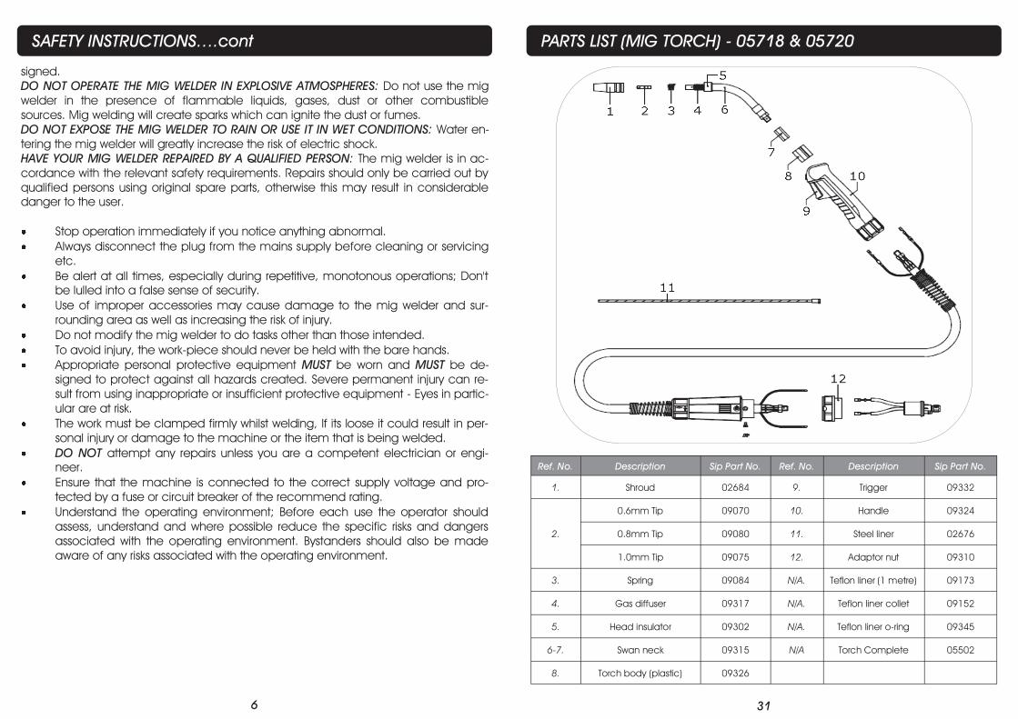
PARTS LIST (MIG TORCH) - 05718 & 05720
Ref. No. Description Sip Part No. Ref. No. Description Sip Part No.
1. Shroud 02684 9. Trigger 09332
0.6mm Tip 09070 10. Handle 09324
2. 0.8mm Tip 09080 11. Steel liner 02676
1.0mm Tip 09075 12. Adaptor nut 09310
3. Spring 09084 N/A. Teflon liner (1 metre) 09173
4. Gas diffuser 09317 N/A. Teflon liner collet 09152
5. Head insulator 09302 N/A. Teflon liner o-ring 09345
6-7. Swan neck 09315 N/A Torch Complete 05502
8. Torch body (plastic) 09326
30
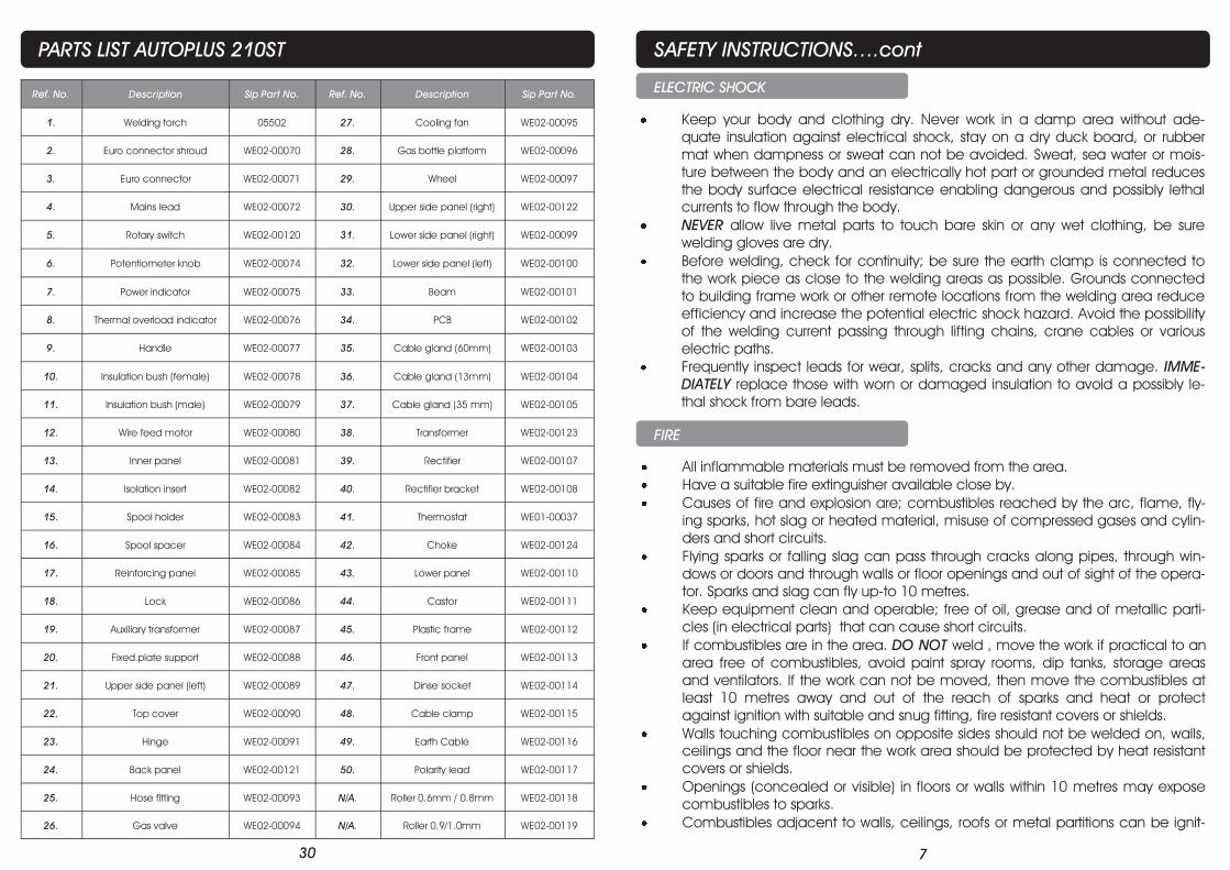
PARTS LIST AUTOPLUS 210ST
Ref. No. Description Sip Part No. Ref. No. Description Sip Part No.
1. Welding torch 05502 27. Cooling fan WE02-00095
2. Euro connector shroud WE02-00070 28. Gas bottle platform WE02-00096
3. Euro connector WE02-00071 29. Wheel WE02-00097
4. Mains lead WE02-00072 30. Upper side panel (right) WE02-00122
5. Rotary switch WE02-00120 31. Lower side panel (right) WE02-00099
6. Potentiometer knob WE02-00074 32. Lower side panel (left) WE02-00100
7. Power indicator WE02-00075 33. Beam WE02-00101
8. Thermal overload indicator WE02-00076 34. PCB WE02-00102
9. Handle WE02-00077 35. Cable gland (60mm) WE02-00103
10. Insulation bush (female) WE02-00078 36. Cable gland (13mm) WE02-00104
11. Insulation bush (male) WE02-00079 37. Cable gland (35 mm) WE02-00105
12. Wire feed motor WE02-00080 38. Transformer WE02-00123
13. Inner panel WE02-00081 39. Rectifier WE02-00107
14. Isolation insert WE02-00082 40. Rectifier bracket WE02-00108
15. Spool holder WE02-00083 41. Thermostat WE01-00037
16. Spool spacer WE02-00084 42. Choke WE02-00124
17. Reinforcing panel WE02-00085 43. Lower panel WE02-00110
18. Lock WE02-00086 44. Castor WE02-00111
19. Auxiliary transformer WE02-00087 45. Plastic frame WE02-00112
20. Fixed plate support WE02-00088 46. Front panel WE02-00113
21. Upper side panel (left) WE02-00089 47. Dinse socket WE02-00114
22. Top cover WE02-00090 48. Cable clamp WE02-00115
23. Hinge WE02-00091 49. Earth Cable WE02-00116
24. Back panel WE02-00121 50. Polarity lead WE02-00117
25. Hose fitting WE02-00093 N/A. Roller 0.6mm / 0.8mm WE02-00118
26. Gas valve WE02-00094 N/A. Roller 0.9/1.0mm WE02-00119
7
SAFETY INSTRUCTIONS….cont
Keep your body and clothing dry. Never work in a damp area without ade-
quate insulation against electrical shock, stay on a dry duck board, or rubber
mat when dampness or sweat can not be avoided. Sweat, sea water or mois-
ture between the body and an electrically hot part or grounded metal reduces
the body surface electrical resistance enabling dangerous and possibly lethal
currents to flow through the body.
NEVER allow live metal parts to touch bare skin or any wet clothing, be sure
welding gloves are dry.
Before welding, check for continuity; be sure the earth clamp is connected to
the work piece as close to the welding areas as possible. Grounds connected
to building frame work or other remote locations from the welding area reduce
efficiency and increase the potential electric shock hazard. Avoid the possibility
of the welding current passing through lifting chains, crane cables or various
electric paths.
Frequently inspect leads for wear, splits, cracks and any other damage. IMME-
DIATELY replace those with worn or damaged insulation to avoid a possibly le-
thal shock from bare leads.
ELECTRIC SHOCK
FIRE
All inflammable materials must be removed from the area.
Have a suitable fire extinguisher available close by.
Causes of fire and explosion are; combustibles reached by the arc, flame, fly-
ing sparks, hot slag or heated material, misuse of compressed gases and cylin-
ders and short circuits.
Flying sparks or falling slag can pass through cracks along pipes, through win-
dows or doors and through walls or floor openings and out of sight of the opera-
tor. Sparks and slag can fly up-to 10 metres.
Keep equipment clean and operable; free of oil, grease and of metallic parti-
cles (in electrical parts) that can cause short circuits.
If combustibles are in the area. DO NOT weld , move the work if practical to an
area free of combustibles, avoid paint spray rooms, dip tanks, storage areas
and ventilators. If the work can not be moved, then move the combustibles at
least 10 metres away and out of the reach of sparks and heat or protect
against ignition with suitable and snug fitting, fire resistant covers or shields.
Walls touching combustibles on opposite sides should not be welded on, walls,
ceilings and the floor near the work area should be protected by heat resistant
covers or shields.
Openings (concealed or visible) in floors or walls within 10 metres may expose
combustibles to sparks.
Combustibles adjacent to walls, ceilings, roofs or metal partitions can be ignit-
8
ed by radiant or conducted heat.
After the work is done, check that the area is free of sparks, glowing embers and
flames.
An empty container that has held combustibles, or that can produce flamma-
ble or toxic vapours when heated, must never be welded, unless the container
has first been cleaned. Consult HSE INDG214, HSG250 and CS15. HSE docu-
ment CS15 includes information on cleaning by thorough steam or solvent/
caustic cleaning followed by purging and inserting with nitrogen, carbon diox-
ide or water filling just below working level.
A container with unknown contents should be treated as if it contained combus-
tibles (see previous paragraph), DO NOT depend on sense of smell or sight to
determine if it is safe to weld.
Hollow items must be vented before welding as they can explode.
Explosive atmosphere; Never weld when the air may contain flammable dust,
gas or liquid vapours (such as petrol).
SAFETY INSTRUCTIONS….cont
The electric welding arc must not be observed with the naked eye. Always use a
welding mask and ensure the welding mask is fitted with the correct shade of
filter lens for the welding current level.
Welding gauntlet gloves should be worn to protect the hands from burns, non-
synthetic overalls with buttons at the neck and wrist, or similar clothing should be
worn. Greasy overalls should not be worn. Wear suitable protective footwear.
Wear protective clothing, welding gauntlet gloves, hat and high safety toe
shoes.
Avoid oily or greasy clothing, a spark may ignite them.
Hot metal such as electrode stubs and work pieces should never be handled
without gloves.
First aid facilities and a qualified first aid person should be available for each
shift unless medical facilities are close by for immediate treatment of flash burns
to the eyes and skin.
Flammable hair products should not be used by persons intending to weld.
Warn bystanders not to watch the arc and not to expose themselves to the
welding-arc rays or to hot metal.
Keep children away whilst welding, they may not be aware that looking at an
arc can cause serious eye damage.
Protect other nearby personnel from arc rays and hot sparks with a suitable non-
flammable partition.
GLARE AND BURNS
29
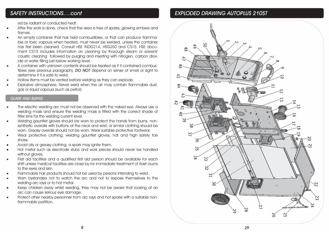
EXPLODED DRAWING AUTOPLUS 210ST
28
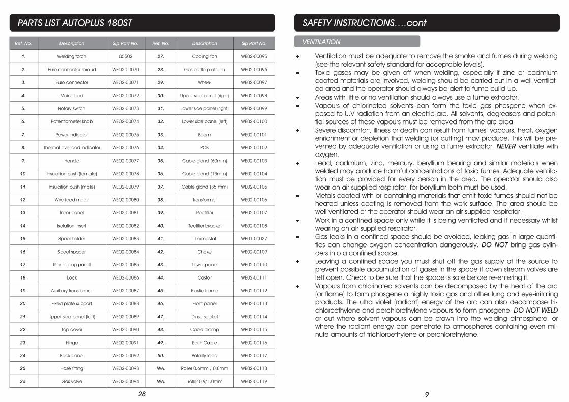
Ref. No. Description Sip Part No. Ref. No. Description Sip Part No.
1. Welding torch 05502 27. Cooling fan WE02-00095
2. Euro connector shroud WE02-00070 28. Gas bottle platform WE02-00096
3. Euro connector WE02-00071 29. Wheel WE02-00097
4. Mains lead WE02-00072 30. Upper side panel (right) WE02-00098
5. Rotary switch WE02-00073 31. Lower side panel (right) WE02-00099
6. Potentiometer knob WE02-00074 32. Lower side panel (left) WE02-00100
7. Power indicator WE02-00075 33. Beam WE02-00101
8. Thermal overload indicator WE02-00076 34. PCB WE02-00102
9. Handle WE02-00077 35. Cable gland (60mm) WE02-00103
10. Insulation bush (female) WE02-00078 36. Cable gland (13mm) WE02-00104
11. Insulation bush (male) WE02-00079 37. Cable gland (35 mm) WE02-00105
12. Wire feed motor WE02-00080 38. Transformer WE02-00106
13. Inner panel WE02-00081 39. Rectifier WE02-00107
14. Isolation insert WE02-00082 40. Rectifier bracket WE02-00108
15. Spool holder WE02-00083 41. Thermostat WE01-00037
16. Spool spacer WE02-00084 42. Choke WE02-00109
17. Reinforcing panel WE02-00085 43. Lower panel WE02-00110
18. Lock WE02-00086 44. Castor WE02-00111
19. Auxiliary transformer WE02-00087 45. Plastic frame WE02-00112
20. Fixed plate support WE02-00088 46. Front panel WE02-00113
21. Upper side panel (left) WE02-00089 47. Dinse socket WE02-00114
22. Top cover WE02-00090 48. Cable clamp WE02-00115
23. Hinge WE02-00091 49. Earth Cable WE02-00116
24. Back panel WE02-00092 50. Polarity lead WE02-00117
25. Hose fitting WE02-00093 N/A. Roller 0.6mm / 0.8mm WE02-00118
26. Gas valve WE02-00094 N/A. Roller 0.9/1.0mm WE02-00119
PARTS LIST AUTOPLUS 180ST
9
SAFETY INSTRUCTIONS….cont
Ventilation must be adequate to remove the smoke and fumes during welding
(see the relevant safety standard for acceptable levels).
Toxic gases may be given off when welding, especially if zinc or cadmium
coated materials are involved, welding should be carried out in a well ventilat-
ed area and the operator should always be alert to fume build-up.
Areas with little or no ventilation should always use a fume extractor.
Vapours of chlorinated solvents can form the toxic gas phosgene when ex-
posed to U.V radiation from an electric arc. All solvents, degreasers and poten-
tial sources of these vapours must be removed from the arc area.
Severe discomfort, illness or death can result from fumes, vapours, heat, oxygen
enrichment or depletion that welding (or cutting) may produce. This will be pre-
vented by adequate ventilation or using a fume extractor. NEVER ventilate with
oxygen.
Lead, cadmium, zinc, mercury, beryllium bearing and similar materials when
welded may produce harmful concentrations of toxic fumes. Adequate ventila-
tion must be provided for every person in the area. The operator should also
wear an air supplied respirator, for beryllium both must be used.
Metals coated with or containing materials that emit toxic fumes should not be
heated unless coating is removed from the work surface. The area should be
well ventilated or the operator should wear an air supplied respirator.
Work in a confined space only while it is being ventilated and if necessary whilst
wearing an air supplied respirator.
Gas leaks in a confined space should be avoided, leaking gas in large quanti-
ties can change oxygen concentration dangerously. DO NOT bring gas cylin-
ders into a confined space.
Leaving a confined space you must shut off the gas supply at the source to
prevent possible accumulation of gases in the space if down stream valves are
left open. Check to be sure that the space is safe before re-entering it.
Vapours from chlorinated solvents can be decomposed by the heat of the arc
(or flame) to form phosgene a highly toxic gas and other lung and eye-irritating
products. The ultra violet (radiant) energy of the arc can also decompose tri-
chloroethylene and perchlorethylene vapours to form phosgene. DO NOT WELD
or cut where solvent vapours can be drawn into the welding atmosphere, or
where the radiant energy can penetrate to atmospheres containing even mi-
nute amounts of trichloroethylene or perchlorethylene.
VENTILATION
10
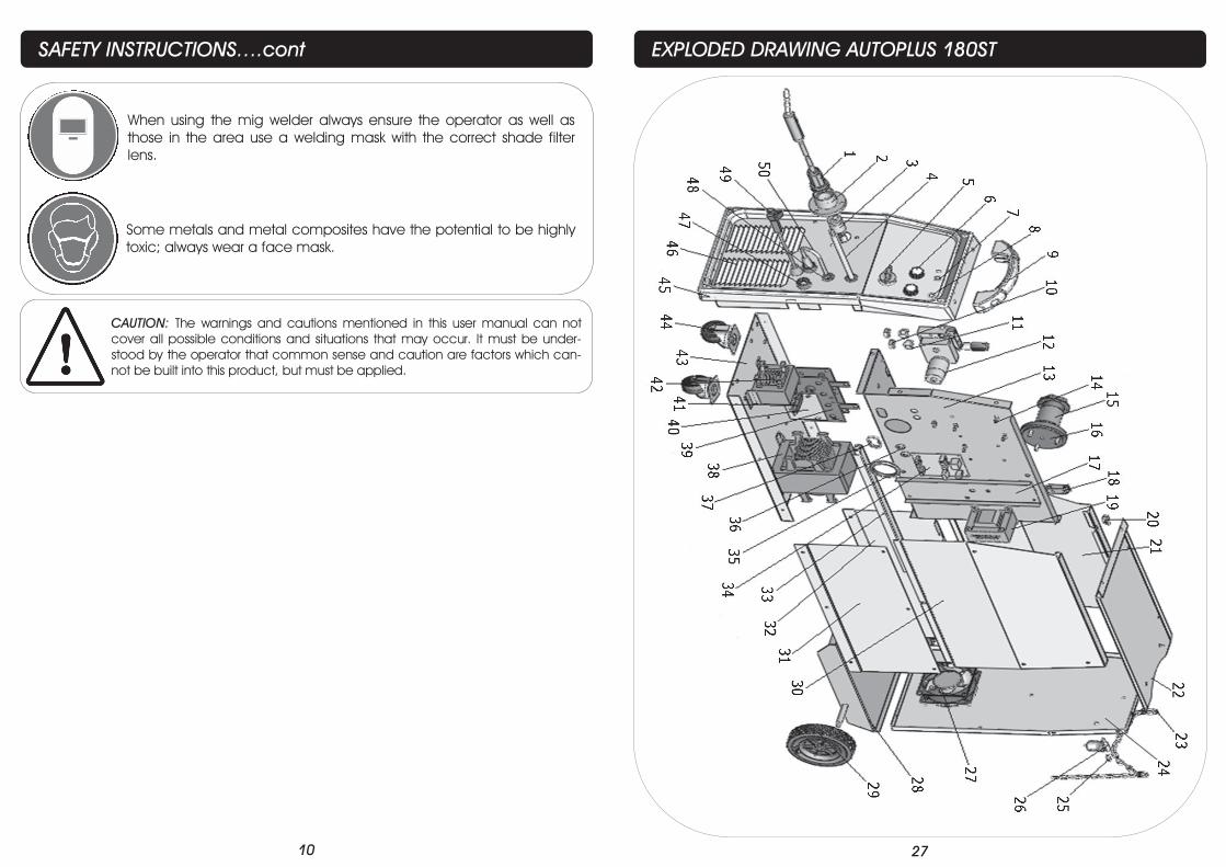
SAFETY INSTRUCTIONS….cont
Some metals and metal composites have the potential to be highly
toxic; always wear a face mask.
When using the mig welder always ensure the operator as well as
those in the area use a welding mask with the correct shade filter
lens.
CAUTION: The warnings and cautions mentioned in this user manual can not
cover all possible conditions and situations that may occur. It must be under-
stood by the operator that common sense and caution are factors which can-
not be built into this product, but must be applied.
27
EXPLODED DRAWING AUTOPLUS 180ST
26
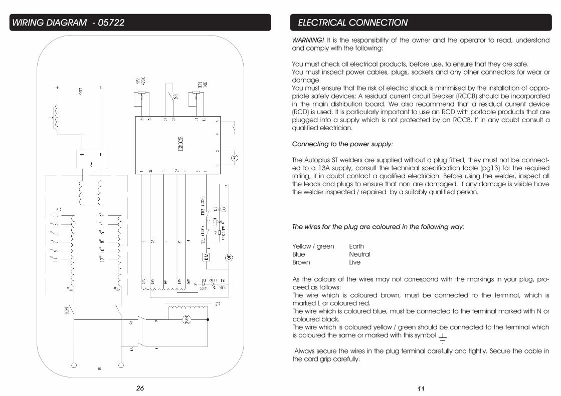
WIRING DIAGRAM - 05722
11
ELECTRICAL CONNECTION
WARNING! It is the responsibility of the owner and the operator to read, understand
and comply with the following:
You must check all electrical products, before use, to ensure that they are safe.
You must inspect power cables, plugs, sockets and any other connectors for wear or
damage.
You must ensure that the risk of electric shock is minimised by the installation of appro-
priate safety devices; A residual current circuit Breaker (RCCB) should be incorporated
in the main distribution board. We also recommend that a residual current device
(RCD) is used. It is particularly important to use an RCD with portable products that are
plugged into a supply which is not protected by an RCCB. If in any doubt consult a
qualified electrician.
Connecting to the power supply:
The Autoplus ST welders are supplied without a plug fitted, they must not be connect-
ed to a 13A supply, consult the technical specification table (pg13) for the required
rating, if in doubt contact a qualified electrician. Before using the welder, inspect all
the leads and plugs to ensure that non are damaged. If any damage is visible have
the welder inspected / repaired by a suitably qualified person.
The wires for the plug are coloured in the following way:
Yellow / green Earth
Blue Neutral
Brown Live
As the colours of the wires may not correspond with the markings in your plug, pro-
ceed as follows:
The wire which is coloured brown, must be connected to the terminal, which is
marked L or coloured red.
The wire which is coloured blue, must be connected to the terminal marked with N or
coloured black.
The wire which is coloured yellow / green should be connected to the terminal which
is coloured the same or marked with this symbol
Always secure the wires in the plug terminal carefully and tightly. Secure the cable in
the cord grip carefully.
12
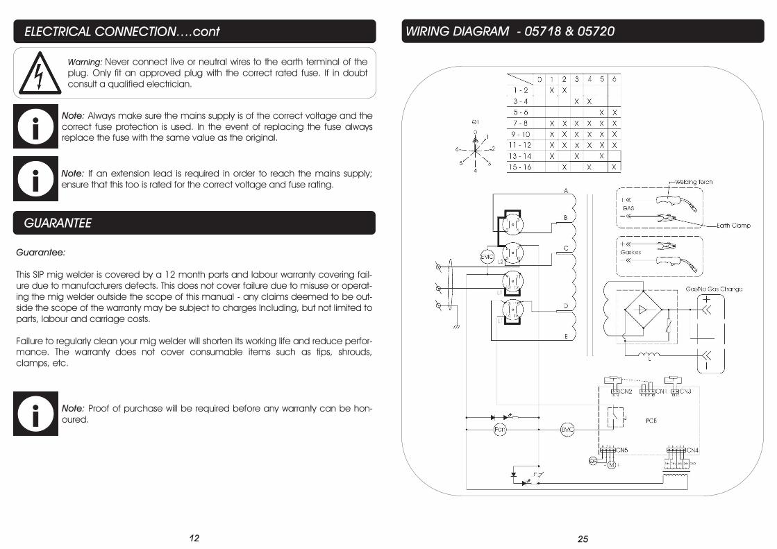
Warning: Never connect live or neutral wires to the earth terminal of the
plug. Only fit an approved plug with the correct rated fuse. If in doubt
consult a qualified electrician.
Note: Always make sure the mains supply is of the correct voltage and the
correct fuse protection is used. In the event of replacing the fuse always
replace the fuse with the same value as the original.
Note: If an extension lead is required in order to reach the mains supply;
ensure that this too is rated for the correct voltage and fuse rating.
ELECTRICAL CONNECTION….cont
Guarantee:
This SIP mig welder is covered by a 12 month parts and labour warranty covering fail-
ure due to manufacturers defects. This does not cover failure due to misuse or operat-
ing the mig welder outside the scope of this manual - any claims deemed to be out-
side the scope of the warranty may be subject to charges Including, but not limited to
parts, labour and carriage costs.
Failure to regularly clean your mig welder will shorten its working life and reduce perfor-
mance. The warranty does not cover consumable items such as tips, shrouds,
clamps, etc.
GUARANTEE
Note: Proof of purchase will be required before any warranty can be hon-
oured.
25
WIRING DIAGRAM - 05718 & 05720
24
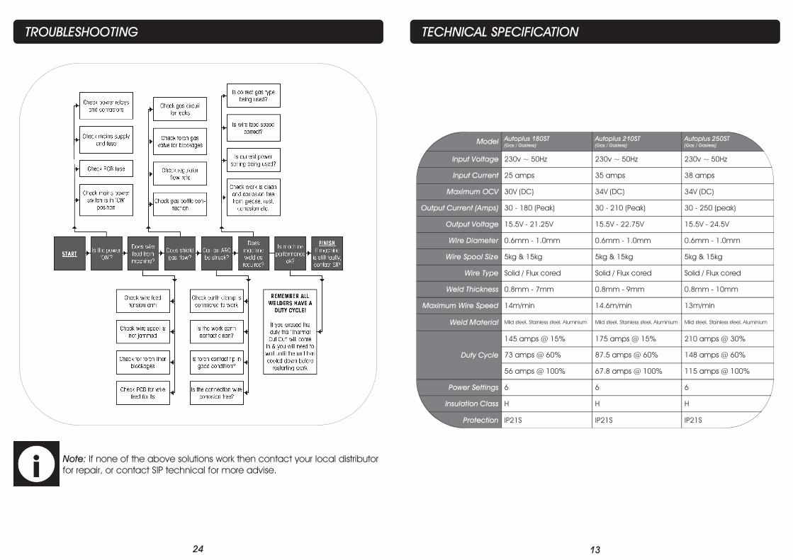
TROUBLESHOOTING
Note: If none of the above solutions work then contact your local distributor
for repair, or contact SIP technical for more advise.
13
TECHNICAL SPECIFICATION
Model Autoplus 180ST
(Gas / Gasless)
Autoplus 210ST
(Gas / Gasless)
Autoplus 250ST
(Gas / Gasless)
Input Voltage 230v ~ 50Hz 230v ~ 50Hz 230v ~ 50Hz
Input Current 25 amps 35 amps 38 amps
Maximum OCV 30V (DC) 34V (DC) 34V (DC)
Output Current (Amps) 30 - 180 (Peak) 30 - 210 (Peak) 30 - 250 (peak)
Output Voltage 15.5V - 21.25V 15.5V - 22.75V 15.5V - 24.5V
Wire Diameter 0.6mm - 1.0mm 0.6mm - 1.0mm 0.6mm - 1.0mm
Wire Spool Size 5kg & 15kg 5kg & 15kg 5kg & 15kg
Wire Type Solid / Flux cored Solid / Flux cored Solid / Flux cored
Weld Thickness 0.8mm - 7mm 0.8mm - 9mm 0.8mm - 10mm
Maximum Wire Speed 14m/min 14.6m/min 13m/min
Weld Material Mild steel, Stainless steel, Aluminium Mild steel, Stainless steel, Aluminium Mild steel, Stainless steel, Aluminium
Duty Cycle
145 amps @ 15% 175 amps @ 15% 210 amps @ 30%
73 amps @ 60% 87.5 amps @ 60% 148 amps @ 60%
56 amps @ 100% 67.8 amps @ 100% 115 amps @ 100%
Power Settings 6 6 6
Insulation Class H H H
Protection IP21S IP21S IP21S
14
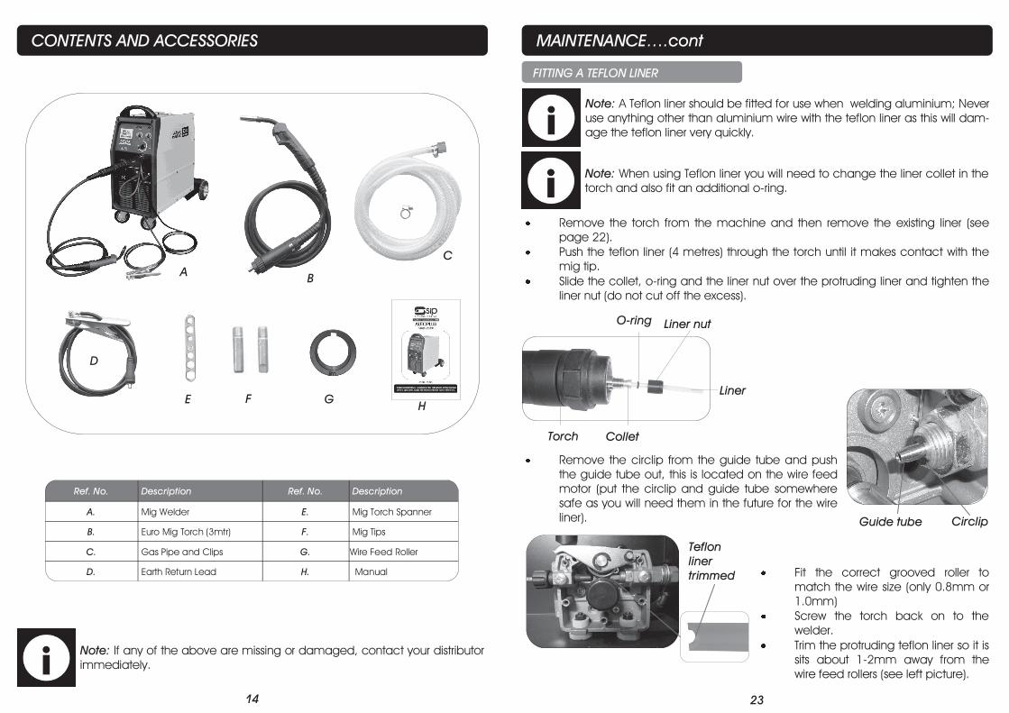
CONTENTS AND ACCESSORIES
Note: If any of the above are missing or damaged, contact your distributor
immediately.
B
C
E F
D
H
A
G
Ref. No. Description Ref. No. Description
A. Mig Welder E. Mig Torch Spanner
B. Euro Mig Torch (3mtr) F. Mig Tips
C. Gas Pipe and Clips G. Wire Feed Roller
D. Earth Return Lead H. Manual
23
MAINTENANCE….cont
FITTING A TEFLON LINER
Remove the torch from the machine and then remove the existing liner (see
page 22).
Push the teflon liner (4 metres) through the torch until it makes contact with the
mig tip.
Slide the collet, o-ring and the liner nut over the protruding liner and tighten the
liner nut (do not cut off the excess).
Remove the circlip from the guide tube and push
the guide tube out, this is located on the wire feed
motor (put the circlip and guide tube somewhere
safe as you will need them in the future for the wire
liner).
Note: A Teflon liner should be fitted for use when welding aluminium; Never
use anything other than aluminium wire with the teflon liner as this will dam-
age the teflon liner very quickly.
Fit the correct grooved roller to
match the wire size (only 0.8mm or
1.0mm)
Screw the torch back on to the
welder.
Trim the protruding teflon liner so it is
sits about 1-2mm away from the
wire feed rollers (see left picture).
Guide tube Circlip
Teflon
liner
trimmed
Note: When using Teflon liner you will need to change the liner collet in the
torch and also fit an additional o-ring.
Torch Collet
Liner
O-ring Liner nut
22
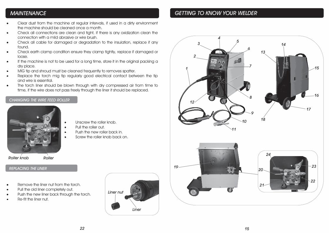
MAINTENANCE
Clear dust from the machine at regular intervals, if used in a dirty environment
the machine should be cleaned once a month.
Check all connections are clean and tight, if there is any oxidization clean the
connection with a mild abrasive or wire brush.
Check all cable for damaged or degradation to the insulation, replace if any
found.
Check earth clamp condition ensure they clamp tightly, replace if damaged or
loose.
If the machine is not to be used for a long time, store it in the original packing a
dry place.
MIG tip and shroud must be cleaned frequently to removes spatter.
Replace the torch mig tip regularly good electrical contact between the tip
and wire is essential.
The torch liner should be blown through with dry compressed air from time to
time, if the wire does not pass freely through the liner it should be replaced.
CHANGING THE WIRE FEED ROLLER
Unscrew the roller knob.
Pull the roller out.
Push the new roller back in.
Screw the roller knob back on.
Roller knob Roller
REPLACING THE LINER
Remove the liner nut from the torch.
Pull the old liner completely out.
Push the new liner back through the torch.
Re-fit the liner nut.
Liner nut
Liner
15
GETTING TO KNOW YOUR WELDER
20
23
24
21
22
19
1
2
3
4
5
6
8
9
10
13
14
15
16
17
18
7
11
12
16
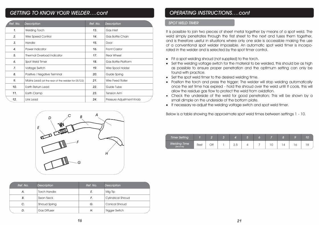
GETTING TO KNOW YOUR WELDER….cont
Ref. No. Description Ref. No. Description
A. Torch Handle E. Mig Tip
B. Swan Neck F. Cylindrical Shroud
C. Shroud Spring G. Conical Shroud
D. Gas Diffuser H. Trigger Switch
Ref. No. Description Ref. No. Description
1. Welding Torch 13. Gas Inlet
2. Wire Speed Control 14. Gas Bottle Chain
3. Handle 15. Door
4. Power Indicator 16. Front Castor
5. Thermal Overload Indicator 17. Rear Wheel
6. Spot Weld Timer 18. Gas Bottle Platform
7. Voltage Switch 19. Wire Spool Holder
8. Positive / Negative Terminal 20. Guide Spring
9. Mains Lead (at the rear of the welder for 05722) 21. Wire Feed Roller
10. Earth Return Lead 22. Guide Tube
11. Earth Clamp 23. Tension Arm
12. Link Lead 24. Pressure Adjustment Knob
B D
C
F
A
G
E
H
21
SPOT WELD TIMER
It is possible to join two pieces of sheet metal together by means of a spot weld. The
weld simply penetrates through the first sheet to the next and fuses them together,
and is therefore useful in situations where only one side is accessible making the use
of a conventional spot welder impossible. An automatic spot weld timer is incorpo-
rated in the welder and is selected by the spot timer control.
Fit a spot welding shroud (not supplied) to the torch.
Set the welding voltage switch for the material to be welded, this should be as high
as possible to ensure proper penetration and the optimum setting can only be
found with practice.
Set the spot weld timer to the desired welding time.
Position the torch and press the trigger; The welder will stop welding automatically
once the set time has expired - hold the shroud over the weld until It cools, this will
allow the residue gas flow to protect the weld from oxidation.
Check the underside of the weld for good penetration; This will be shown by a
small dimple on the underside of the bottom plate.
If necessary re-adjust the welding voltage switch and spot weld timer.
Below is a table showing the approximate spot weld times between settings 1 - 10.
Timer Setting 1 2 3 4 5 6 7 8 9 10
Welding Time
(Seconds)
Rest Off 1 2.5 4 7 10 14 16 18
OPERATING INSTRUCTIONS….cont
20
OPERATING INSTRUCTIONS….cont
Clean the area to be welded, and the earthing point of all rust, paint and con-
taminants etc.
Place the earth clamp on to a cleaned area of the work piece.
Connect the welder to the electrical supply but do not switch on.
PREPARATION FOR WELDING
Set the voltage and wire speed by turning the appropriate controls.
Press the torch trigger and feed the wire out a little.
Cut the wire about 3mm from the mig tip.
Turn the gas on.
Position the torch so the mig tip is around 6mm from the point where the weld-
ing is to commence.
Press the torch trigger and move the torch slowly in the chosen direction.
Once the weld is complete, release the torch trigger.
WELDING
Note: If the welder has a humming sound and a blob forms on the tip end, then you have insufficient wire
feed speed and it should be increased. If the welder has an erratic sound and the torch feels that the wire
is hitting against the work, then you have the wire feed speed to high and it should be reduced, when the
wire feed speed is correct you should get a steady crackling sound.
Note: For future reference make a note of the voltage and wire speed set-
ting for the material that has been welded.
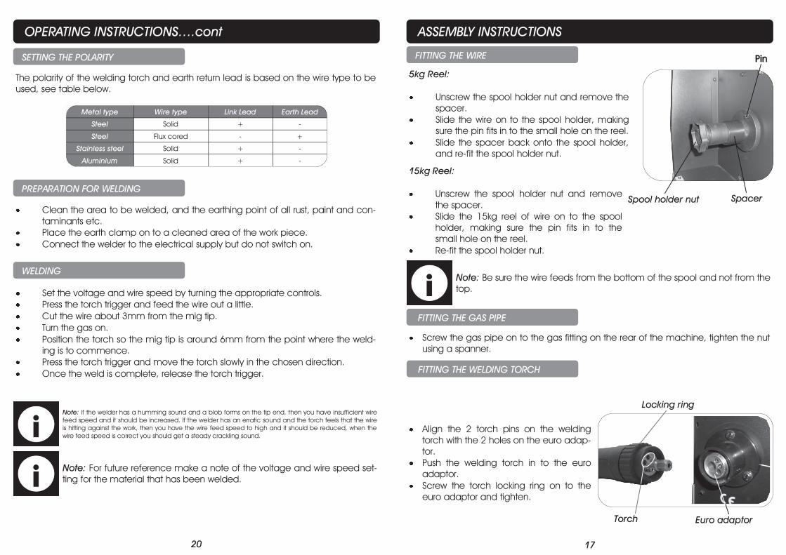
The polarity of the welding torch and earth return lead is based on the wire type to be
used, see table below.
SETTING THE POLARITY
Metal type Wire type Link Lead Earth Lead
Steel Solid + -
Steel Flux cored - +
Stainless steel Solid + -
Aluminium Solid + -
17
ASSEMBLY INSTRUCTIONS
FITTING THE WIRE
5kg Reel:
Unscrew the spool holder nut and remove the
spacer.
Slide the wire on to the spool holder, making
sure the pin fits in to the small hole on the reel.
Slide the spacer back onto the spool holder,
and re-fit the spool holder nut.
15kg Reel:
Unscrew the spool holder nut and remove
the spacer.
Slide the 15kg reel of wire on to the spool
holder, making sure the pin fits in to the
small hole on the reel.
Re-fit the spool holder nut.
FITTING THE GAS PIPE
Screw the gas pipe on to the gas fitting on the rear of the machine, tighten the nut
using a spanner.
FITTING THE WELDING TORCH
Align the 2 torch pins on the welding
torch with the 2 holes on the euro adap-
tor.
Push the welding torch in to the euro
adaptor.
Screw the torch locking ring on to the
euro adaptor and tighten.
Note: Be sure the wire feeds from the bottom of the spool and not from the
top.
Spool holder nut Spacer
Pin
Locking ring
Euro adaptor Torch
18
OPERATING INSTRUCTIONS
FEEDING THE WIRE
Remove the shroud from the torch by rotating
the shroud clockwise and pulling at the same
time.
Remove the mig tip.
Push the pressure adjustment knob to the left
so it takes the pressure from the tension arm,
(see right picture).
Remove the free end of the mig wire from the side of the wire spool, trim off the
distorted end of the wire with a pair of wire cutters; Hold the wire carefully as it
will try to unwind from the spool.
Lift the tension arm up.
Feed the wire through the inlet guide spring, over the wire feed roller and into
the guide tube (you may need to straighten the first 50mm of wire if it doesn't fit
in to the guide tube).
Lower the tension arm and ensure the wire sits in the groove of the wire feed
roller.
Push the pressure adjustment knob back up and back onto the tension arm.
Screw the pressure adjustment knob down, but not too tight as it will crush the
wire.
Plug the welder in to the mains supply and switch the welding voltage switch to
position 1.
Hold the torch out straight, press and hold the torch trigger until the wire comes
out from the end of the torch.
Release the torch trigger.
Re-fit the mig tip and shroud.
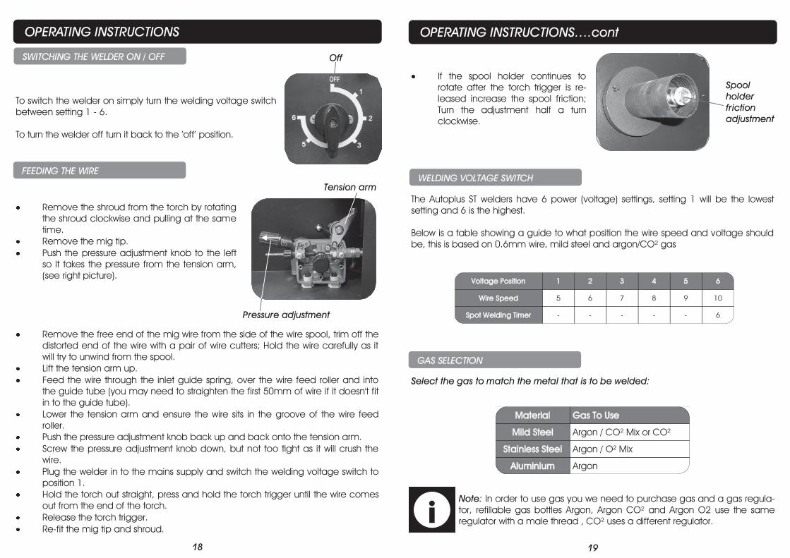
SWITCHING THE WELDER ON / OFF
To switch the welder on simply turn the welding voltage switch
between setting 1 - 6.
To turn the welder off turn it back to the ‘off’ position.
Off
Pressure adjustment
Tension arm
19
OPERATING INSTRUCTIONS….cont
If the spool holder continues to
rotate after the torch trigger is re-
leased increase the spool friction;
Turn the adjustment half a turn
clockwise.
The Autoplus ST welders have 6 power (voltage) settings, setting 1 will be the lowest
setting and 6 is the highest.
Below is a table showing a guide to what position the wire speed and voltage should
be, this is based on 0.6mm wire, mild steel and argon/CO² gas
WELDING VOLTAGE SWITCH
Voltage Position 1 2 3 4 5 6
Wire Speed 5 6 7 8 9 10
Spot Welding Timer - - - - - 6
Spool
holder
friction
adjustment
Select the gas to match the metal that is to be welded:
Note: In order to use gas you we need to purchase gas and a gas regula-
tor, refillable gas bottles Argon, Argon CO² and Argon O2 use the same
regulator with a male thread , CO² uses a different regulator.
GAS SELECTION
Material Gas To Use
Mild Steel Argon / CO² Mix or CO²
Stainless Steel Argon / O² Mix
Aluminium Argon


![[MS-SIP]: Session Initiation Protocol ExtensionsMS-SIP]-160714.pdf · [MS-SIP]: Session Initiation Protocol Extensions ... sip. . . .](https://img.pdfslide.us/doc/110x75/5f144311cb0953247f1ddd57/ms-sip-session-initiation-protocol-extensions-ms-sip-160714pdf-ms-sip.jpg)


![[MS-SIP]: Session Initiation Protocol ExtensionsMS-SIP].pdfSession Initiation Protocol Extensions SIP. . SIP message.](https://img.pdfslide.us/doc/110x75/5e7f8669844925290d6f8357/ms-sip-session-initiation-protocol-extensions-ms-sippdf-session-initiation.jpg)