Embed Size (px)
Citation preview

| Autonomous Mobile Robots
Margarita Chli, Paul Furgale, Marco Hutter, Martin Rufli, Davide Scaramuzza, Roland Siegwart
ASL Autonomous Systems Lab
1
Perception: Sensors
Autonomous Mobile Robots
Davide Scaramuzza
Margarita Chli, Paul Furgale, Marco Hutter, Roland Siegwart
| Autonomous Mobile Robots
Margarita Chli, Paul Furgale, Marco Hutter, Martin Rufli, Davide Scaramuzza, Roland Siegwart
ASL Autonomous Systems Lab
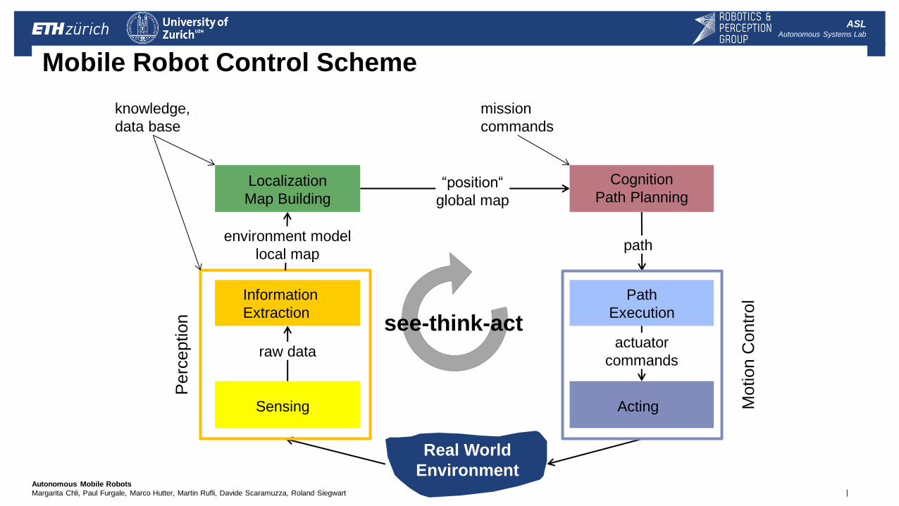
raw data
“position“
global map
Sensing Acting
Information
Extraction
Path
Execution
Cognition
Path Planning
Real World
Environment
Localization
Map Building
Motion C
ontr
ol
Perc
eption
actuator
commands
environment model
local map path
Mobile Robot Control Scheme
knowledge,
data base
mission
commands
see-think-act
| Autonomous Mobile Robots
Margarita Chli, Paul Furgale, Marco Hutter, Martin Rufli, Davide Scaramuzza, Roland Siegwart
ASL Autonomous Systems Lab
Sensors for Mobile Robots
Robot = sensors + actuators
Sensors are the key components for perceiving the environment
Perception is the HOT research topic of the last years
Sensors vary according to:
physical principle
resolution
bandwidth
price
energy needed
| Autonomous Mobile Robots
Margarita Chli, Paul Furgale, Marco Hutter, Martin Rufli, Davide Scaramuzza, Roland Siegwart
ASL Autonomous Systems Lab
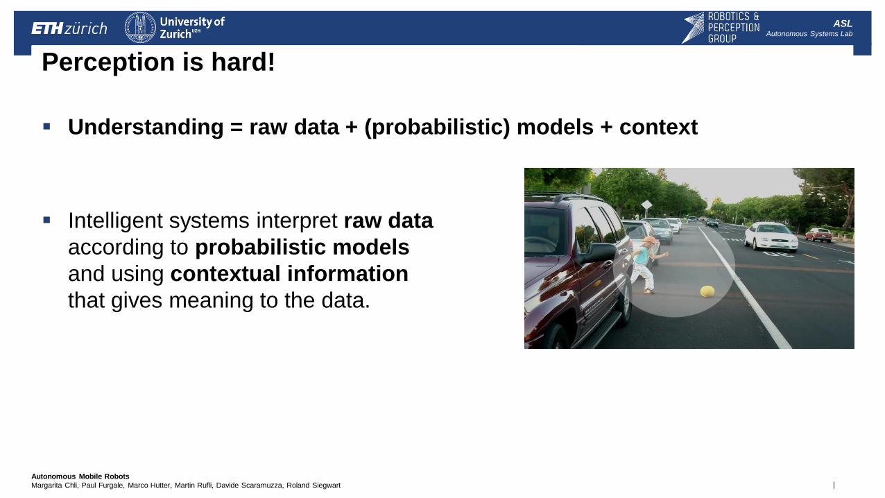
Perception is hard!
Understanding = raw data + (probabilistic) models + context
Intelligent systems interpret raw data
according to probabilistic models
and using contextual information
that gives meaning to the data.
| Autonomous Mobile Robots
Margarita Chli, Paul Furgale, Marco Hutter, Martin Rufli, Davide Scaramuzza, Roland Siegwart
ASL Autonomous Systems Lab
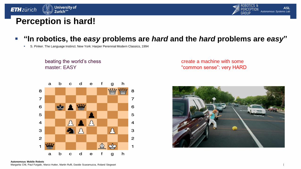
Perception is hard!
“In robotics, the easy problems are hard and the hard problems are easy”
S. Pinker. The Language Instinct. New York: Harper Perennial Modern Classics, 1994
beating the world’s chess
master: EASY
create a machine with some
“common sense”: very HARD
| Autonomous Mobile Robots
Margarita Chli, Paul Furgale, Marco Hutter, Martin Rufli, Davide Scaramuzza, Roland Siegwart
ASL Autonomous Systems Lab
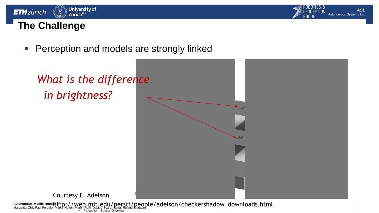
The Challenge
Perception and models are strongly linked
Courtesy E. Adelson
http://web.mit.edu/persci/people/adelson/checkershadow_downloads.html
What is the difference
in brightness?
4 - Perception: Sensor Overview
| Autonomous Mobile Robots
Margarita Chli, Paul Furgale, Marco Hutter, Martin Rufli, Davide Scaramuzza, Roland Siegwart
ASL Autonomous Systems Lab
Com
pres
sing
Info
rmat
ion
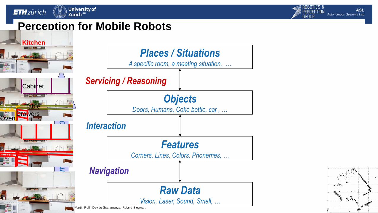
Perception for Mobile Robots
Raw Data Vision, Laser, Sound, Smell, …
Features Corners, Lines, Colors, Phonemes, …
Objects Doors, Humans, Coke bottle, car , …
Places / Situations A specific room, a meeting situation, …
Navigation
Interaction
Servicing / Reasoning Cabinet
Table
Oven Drawers
Kitchen
| Autonomous Mobile Robots
Margarita Chli, Paul Furgale, Marco Hutter, Martin Rufli, Davide Scaramuzza, Roland Siegwart
ASL Autonomous Systems Lab
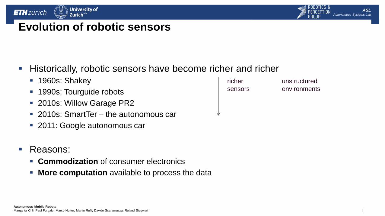
Evolution of robotic sensors
Historically, robotic sensors have become richer and richer
1960s: Shakey
1990s: Tourguide robots
2010s: Willow Garage PR2
2010s: SmartTer – the autonomous car
2011: Google autonomous car
Reasons:
Commodization of consumer electronics
More computation available to process the data
richer
sensors
unstructured
environments
| Autonomous Mobile Robots
Margarita Chli, Paul Furgale, Marco Hutter, Martin Rufli, Davide Scaramuzza, Roland Siegwart
ASL Autonomous Systems Lab
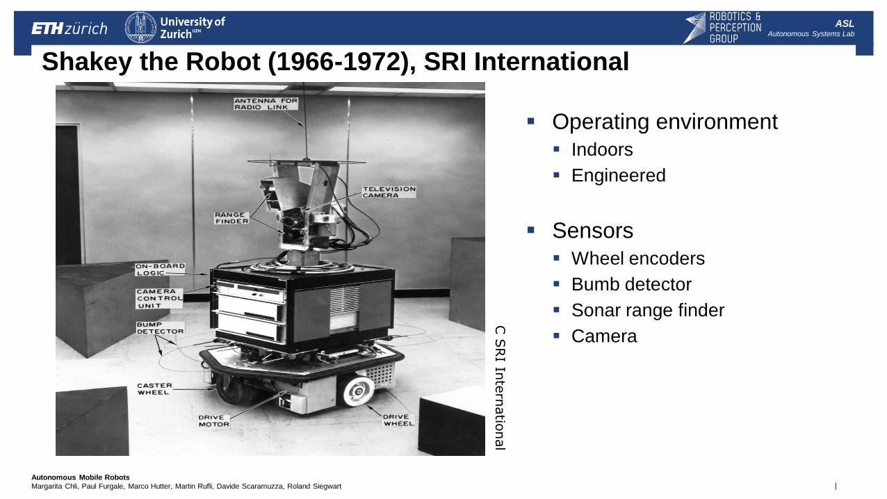
Shakey the Robot (1966-1972), SRI International
C S
RI In
tern
atio
nal
Operating environment
Indoors
Engineered
Sensors
Wheel encoders
Bumb detector
Sonar range finder
Camera

| Autonomous Mobile Robots
Margarita Chli, Paul Furgale, Marco Hutter, Martin Rufli, Davide Scaramuzza, Roland Siegwart
ASL Autonomous Systems Lab
Rhino Tourguide Robot (1995-1998), University of Bonn Operating environment
Indoors (Museum: unstructured and dynamic)
Sensors
Wheel encoders
Ring of sonar sensors
Pan-tilt camera
C U
niv
ers
ity o
f Bonn
| Autonomous Mobile Robots
Margarita Chli, Paul Furgale, Marco Hutter, Martin Rufli, Davide Scaramuzza, Roland Siegwart
ASL Autonomous Systems Lab
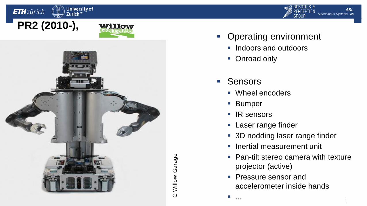
PR2 (2010-), Operating environment
Indoors and outdoors
Onroad only
Sensors
Wheel encoders
Bumper
IR sensors
Laser range finder
3D nodding laser range finder
Inertial measurement unit
Pan-tilt stereo camera with texture
projector (active)
Pressure sensor and
accelerometer inside hands
...
C W
illo
w G
ara
ge
| Autonomous Mobile Robots
Margarita Chli, Paul Furgale, Marco Hutter, Martin Rufli, Davide Scaramuzza, Roland Siegwart
ASL Autonomous Systems Lab
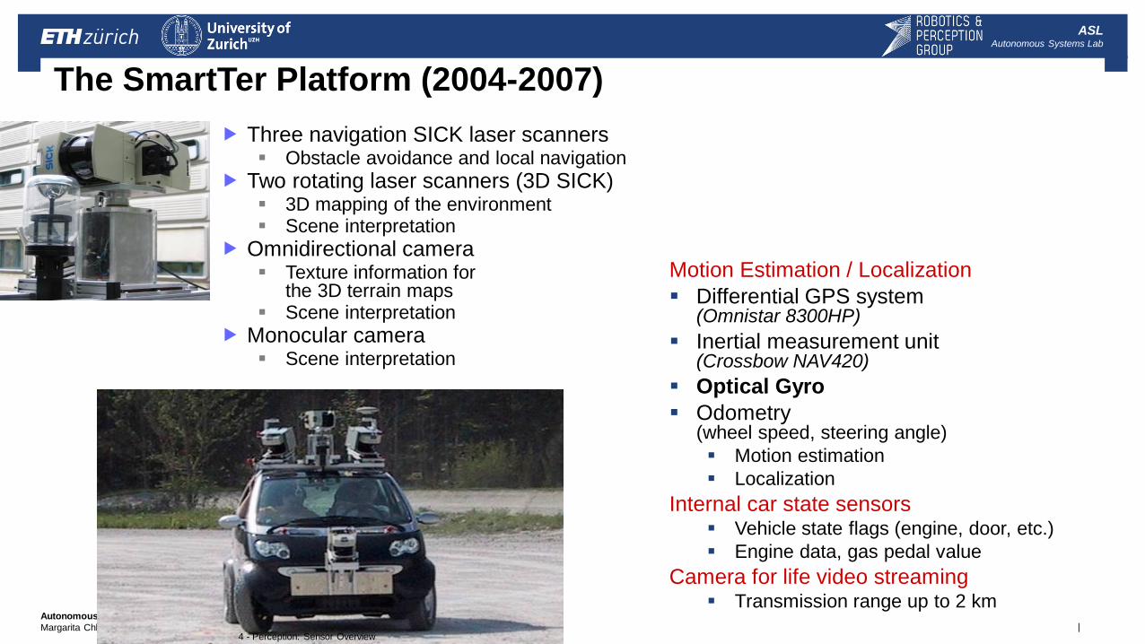
Motion Estimation / Localization
Differential GPS system (Omnistar 8300HP)
Inertial measurement unit (Crossbow NAV420)
Optical Gyro
Odometry (wheel speed, steering angle)
Motion estimation
Localization
Internal car state sensors Vehicle state flags (engine, door, etc.)
Engine data, gas pedal value
Camera for life video streaming Transmission range up to 2 km
4 - Perception: Sensor Overview
The SmartTer Platform (2004-2007)
Three navigation SICK laser scanners Obstacle avoidance and local navigation
Two rotating laser scanners (3D SICK) 3D mapping of the environment Scene interpretation
Omnidirectional camera Texture information for
the 3D terrain maps Scene interpretation
Monocular camera Scene interpretation
| Autonomous Mobile Robots
Margarita Chli, Paul Furgale, Marco Hutter, Martin Rufli, Davide Scaramuzza, Roland Siegwart
ASL Autonomous Systems Lab
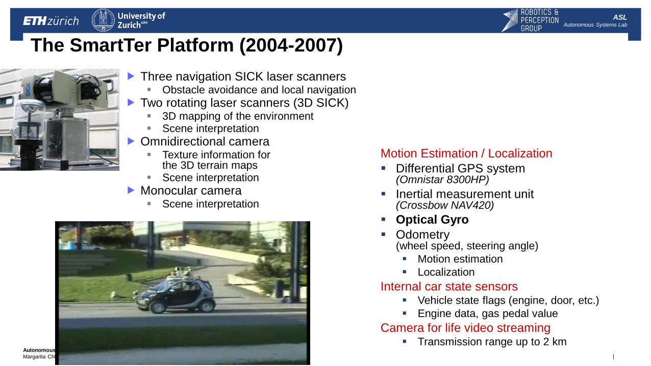
Motion Estimation / Localization
Differential GPS system (Omnistar 8300HP)
Inertial measurement unit (Crossbow NAV420)
Optical Gyro
Odometry (wheel speed, steering angle)
Motion estimation
Localization
Internal car state sensors Vehicle state flags (engine, door, etc.)
Engine data, gas pedal value
Camera for life video streaming Transmission range up to 2 km
4 - Perception: Sensor Overview
The SmartTer Platform (2004-2007)
Three navigation SICK laser scanners Obstacle avoidance and local navigation
Two rotating laser scanners (3D SICK) 3D mapping of the environment Scene interpretation
Omnidirectional camera Texture information for
the 3D terrain maps Scene interpretation
Monocular camera Scene interpretation
| Autonomous Mobile Robots
Margarita Chli, Paul Furgale, Marco Hutter, Martin Rufli, Davide Scaramuzza, Roland Siegwart
ASL Autonomous Systems Lab
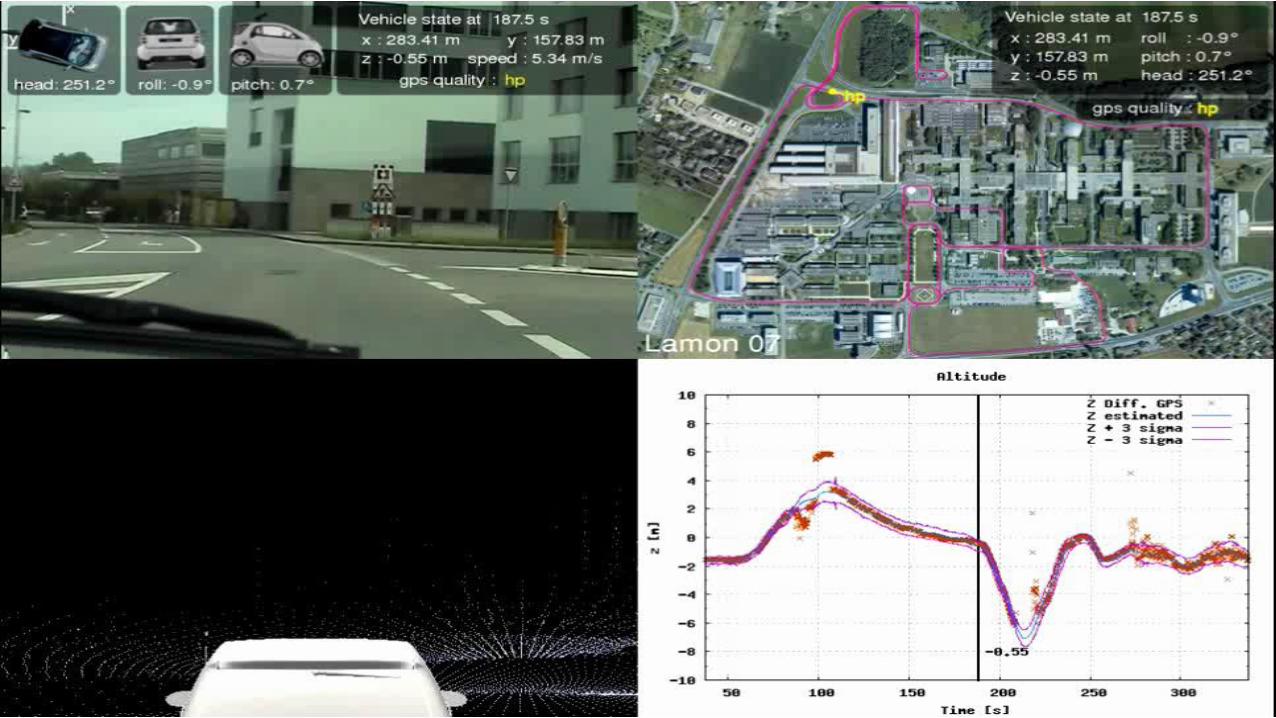
Autonomous Navigation and 3D Mapping
4 - Perception: Sensor Overview
15
| Autonomous Mobile Robots
Margarita Chli, Paul Furgale, Marco Hutter, Martin Rufli, Davide Scaramuzza, Roland Siegwart
ASL Autonomous Systems Lab
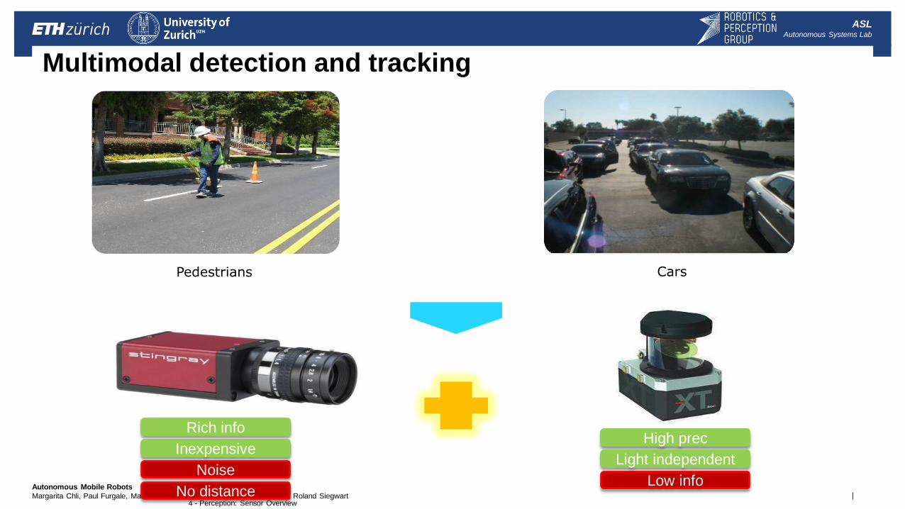
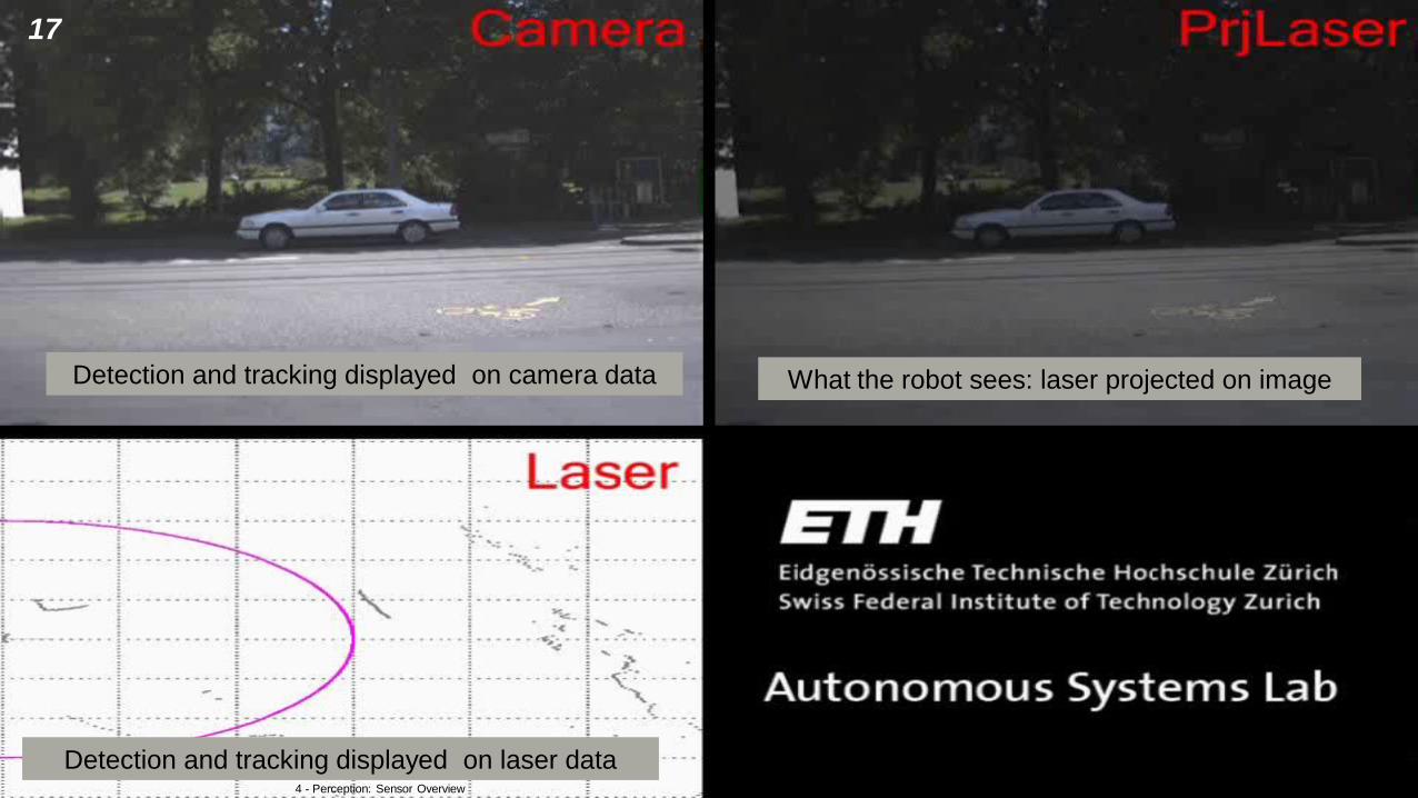
Multimodal detection and tracking
Pedestrians Cars
Rich info
Inexpensive
Noise
No distance
High prec
Low info
Light independent
4 - Perception: Sensor Overview
| Autonomous Mobile Robots
Margarita Chli, Paul Furgale, Marco Hutter, Martin Rufli, Davide Scaramuzza, Roland Siegwart
ASL Autonomous Systems Lab
Detection and tracking displayed on camera data
Detection and tracking displayed on laser data
What the robot sees: laser projected on image
4 - Perception: Sensor Overview
17
| Autonomous Mobile Robots
Margarita Chli, Paul Furgale, Marco Hutter, Martin Rufli, Davide Scaramuzza, Roland Siegwart
ASL Autonomous Systems Lab
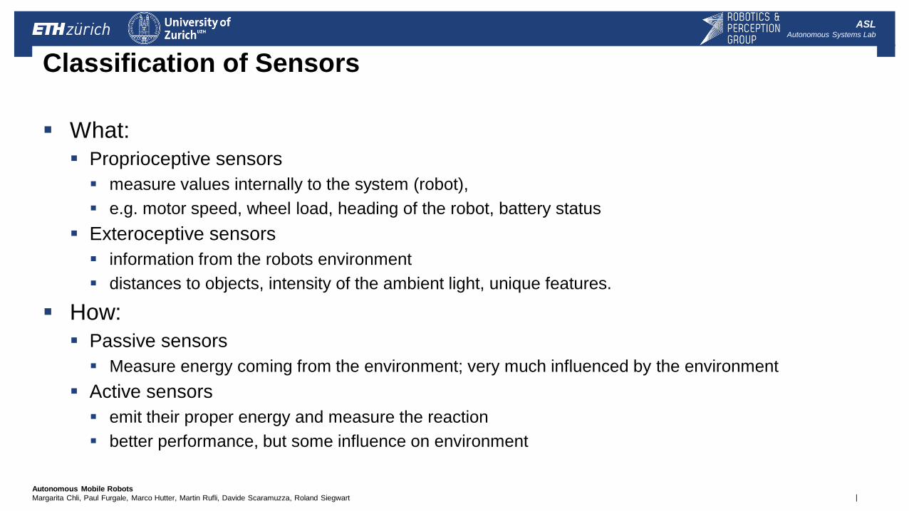
Classification of Sensors
What:
Proprioceptive sensors
measure values internally to the system (robot),
e.g. motor speed, wheel load, heading of the robot, battery status
Exteroceptive sensors
information from the robots environment
distances to objects, intensity of the ambient light, unique features.
How:
Passive sensors
Measure energy coming from the environment; very much influenced by the environment
Active sensors
emit their proper energy and measure the reaction
better performance, but some influence on environment
| Autonomous Mobile Robots
Margarita Chli, Paul Furgale, Marco Hutter, Martin Rufli, Davide Scaramuzza, Roland Siegwart
ASL Autonomous Systems Lab
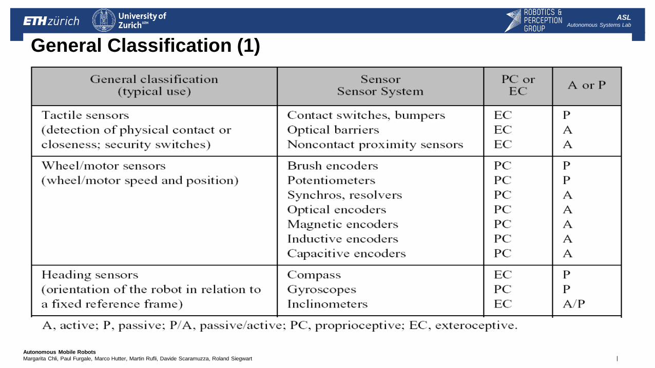
General Classification (1)
| Autonomous Mobile Robots
Margarita Chli, Paul Furgale, Marco Hutter, Martin Rufli, Davide Scaramuzza, Roland Siegwart
ASL Autonomous Systems Lab
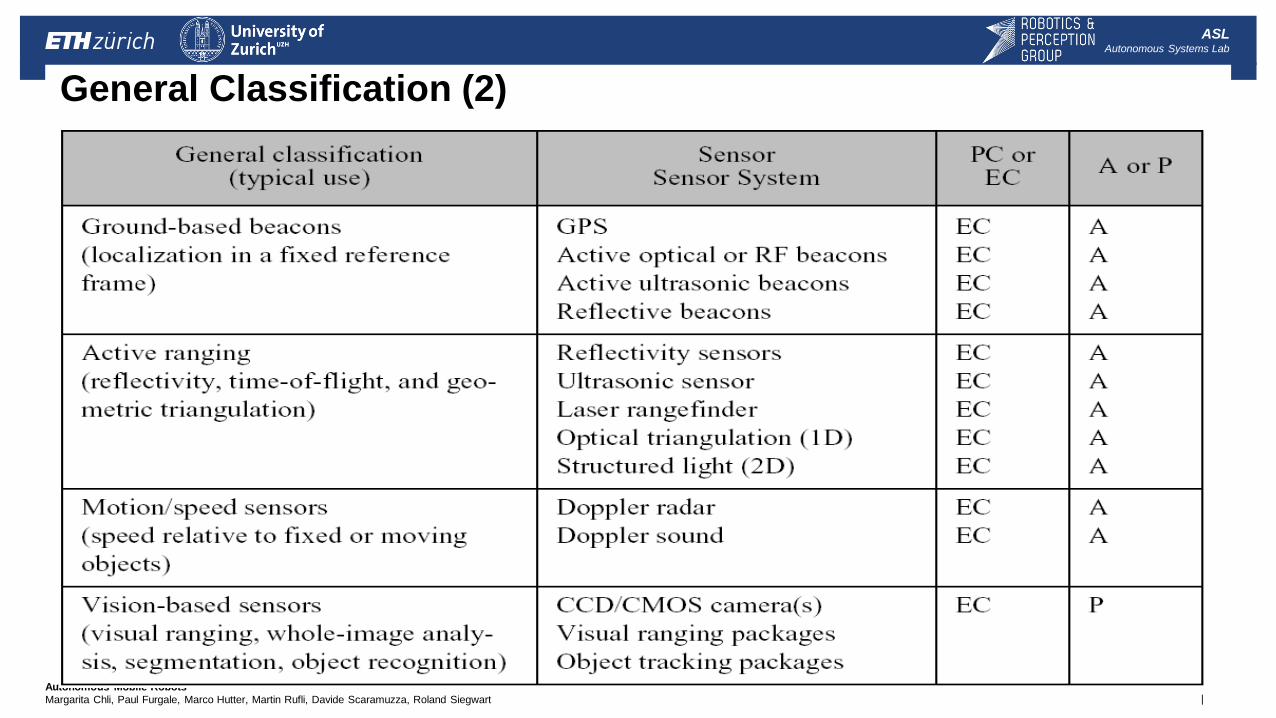
General Classification (2)
| Autonomous Mobile Robots
Margarita Chli, Paul Furgale, Marco Hutter, Martin Rufli, Davide Scaramuzza, Roland Siegwart
ASL Autonomous Systems Lab
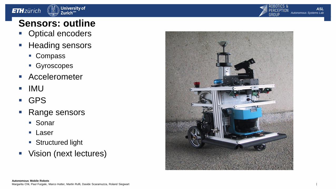
Sensors: outline Optical encoders
Heading sensors
Compass
Gyroscopes
Accelerometer
IMU
GPS
Range sensors
Sonar
Laser
Structured light
Vision (next lectures)
| Autonomous Mobile Robots
Margarita Chli, Paul Furgale, Marco Hutter, Martin Rufli, Davide Scaramuzza, Roland Siegwart
ASL Autonomous Systems Lab
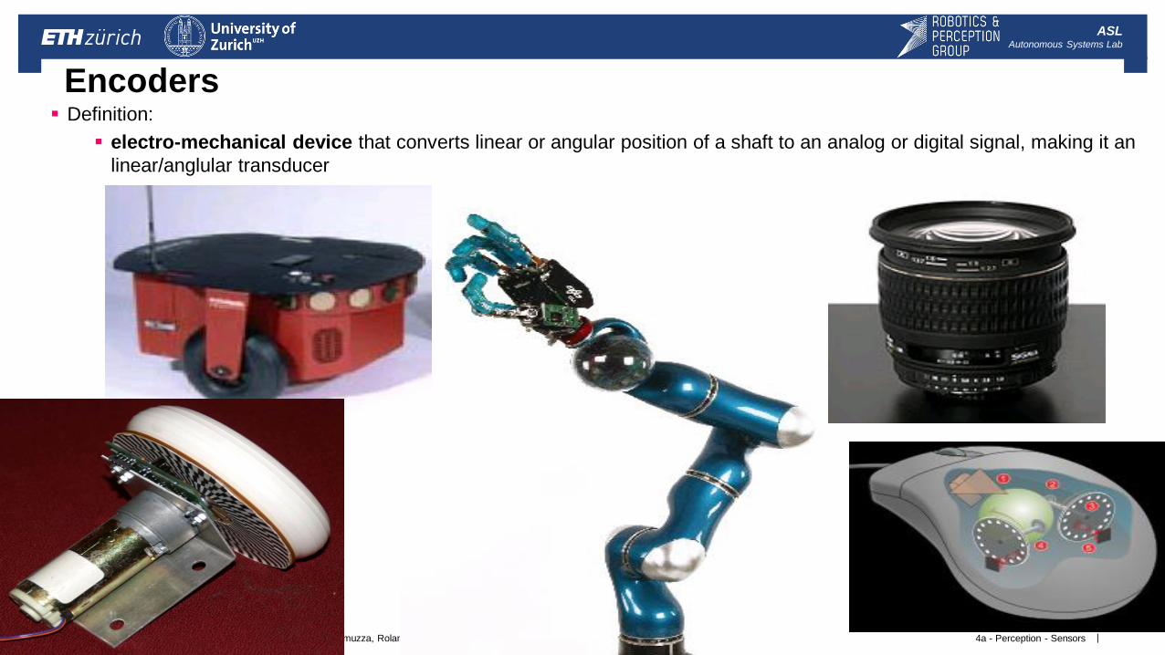
Encoders
4a - Perception - Sensors
Definition:
electro-mechanical device that converts linear or angular position of a shaft to an analog or digital signal, making it an
linear/anglular transducer
| Autonomous Mobile Robots
Margarita Chli, Paul Furgale, Marco Hutter, Martin Rufli, Davide Scaramuzza, Roland Siegwart
ASL Autonomous Systems Lab
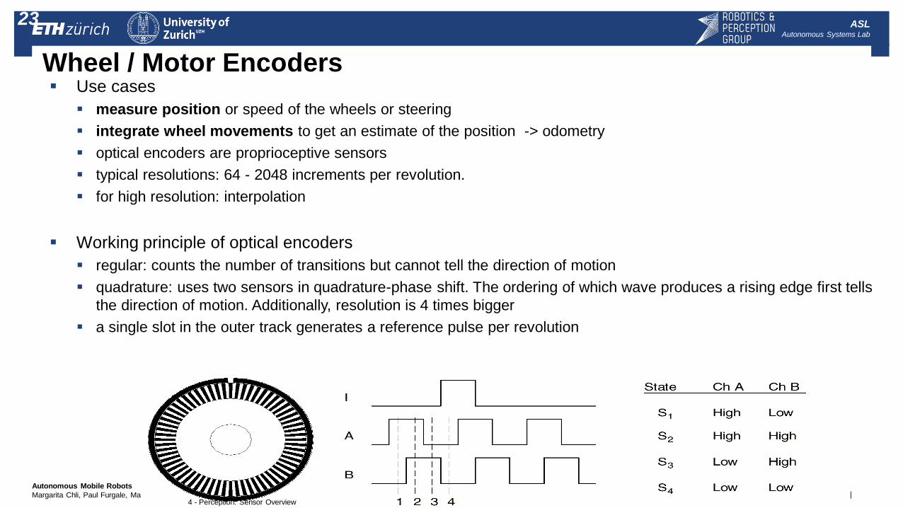
Wheel / Motor Encoders Use cases
measure position or speed of the wheels or steering
integrate wheel movements to get an estimate of the position -> odometry
optical encoders are proprioceptive sensors
typical resolutions: 64 - 2048 increments per revolution.
for high resolution: interpolation
Working principle of optical encoders
regular: counts the number of transitions but cannot tell the direction of motion
quadrature: uses two sensors in quadrature-phase shift. The ordering of which wave produces a rising edge first tells
the direction of motion. Additionally, resolution is 4 times bigger
a single slot in the outer track generates a reference pulse per revolution
4 - Perception: Sensor Overview
23
| Autonomous Mobile Robots
Margarita Chli, Paul Furgale, Marco Hutter, Martin Rufli, Davide Scaramuzza, Roland Siegwart
ASL Autonomous Systems Lab
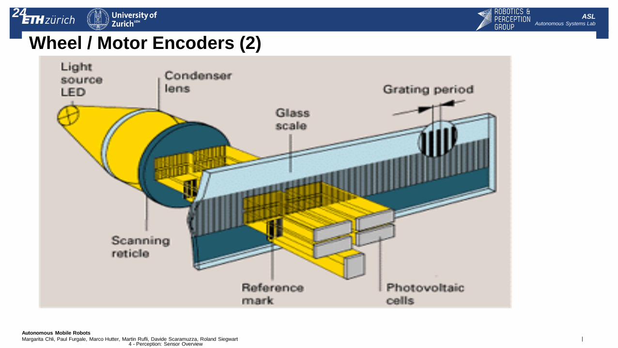
Wheel / Motor Encoders (2)
4 - Perception: Sensor Overview
24
| Autonomous Mobile Robots
Margarita Chli, Paul Furgale, Marco Hutter, Martin Rufli, Davide Scaramuzza, Roland Siegwart
ASL Autonomous Systems Lab
Heading Sensors
Definition:
Heading sensors are sensors that determine the robot’s orientation and inclination with
respect to a given reference
Heading sensors can be proprioceptive (gyroscope, accelerometer) or
exteroceptive (compass, inclinometer).
Allows, together with an appropriate velocity information, to integrate the
movement to a position estimate.
This procedure is called deduced reckoning (ship navigation)
| Autonomous Mobile Robots
Margarita Chli, Paul Furgale, Marco Hutter, Martin Rufli, Davide Scaramuzza, Roland Siegwart
ASL Autonomous Systems Lab
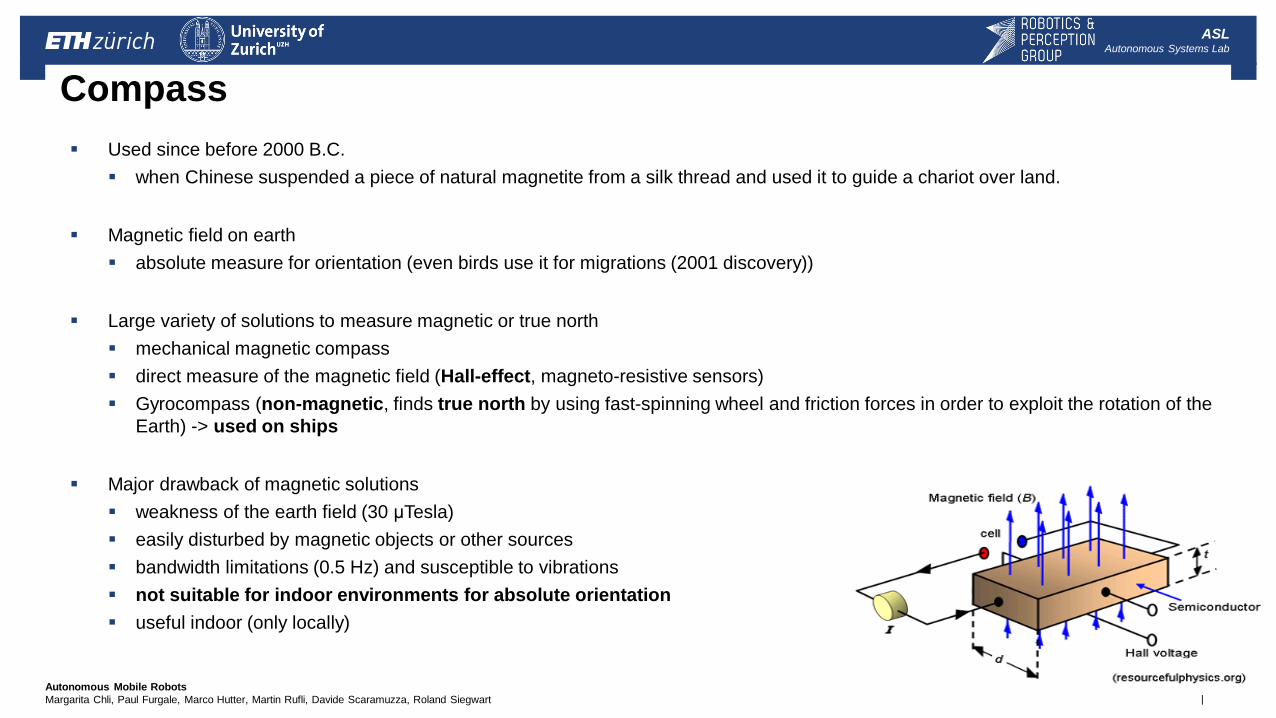
Compass
Used since before 2000 B.C.
when Chinese suspended a piece of natural magnetite from a silk thread and used it to guide a chariot over land.
Magnetic field on earth
absolute measure for orientation (even birds use it for migrations (2001 discovery))
Large variety of solutions to measure magnetic or true north
mechanical magnetic compass
direct measure of the magnetic field (Hall-effect, magneto-resistive sensors)
Gyrocompass (non-magnetic, finds true north by using fast-spinning wheel and friction forces in order to exploit the rotation of the
Earth) -> used on ships
Major drawback of magnetic solutions
weakness of the earth field (30 μTesla)
easily disturbed by magnetic objects or other sources
bandwidth limitations (0.5 Hz) and susceptible to vibrations
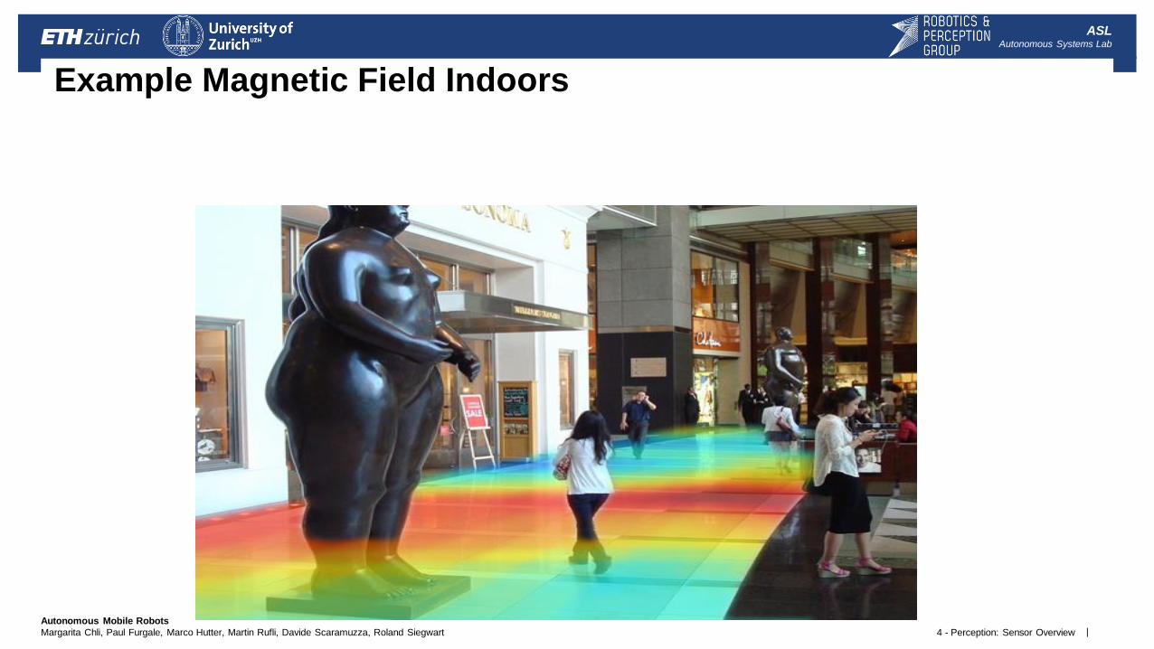
not suitable for indoor environments for absolute orientation
useful indoor (only locally)
| Autonomous Mobile Robots
Margarita Chli, Paul Furgale, Marco Hutter, Martin Rufli, Davide Scaramuzza, Roland Siegwart
ASL Autonomous Systems Lab
4 - Perception: Sensor Overview
What causes the changes of the magnetic fields in indoors environments? Example Magnetic Field Indoors
| Autonomous Mobile Robots
Margarita Chli, Paul Furgale, Marco Hutter, Martin Rufli, Davide Scaramuzza, Roland Siegwart
ASL Autonomous Systems Lab
Gyroscope
Definition:
Heading sensors that preserve their orientation in relation to a fixed reference frame
They provide an absolute measure for the heading of a mobile system.
Two categories, the mechanical and the optical gyroscopes
Mechanical Gyroscopes
Standard gyro (angle)
Rate gyro (speed)
Optical Gyroscopes
Rate gyro (speed)
| Autonomous Mobile Robots
Margarita Chli, Paul Furgale, Marco Hutter, Martin Rufli, Davide Scaramuzza, Roland Siegwart
ASL Autonomous Systems Lab
4a - Perception - Sensors
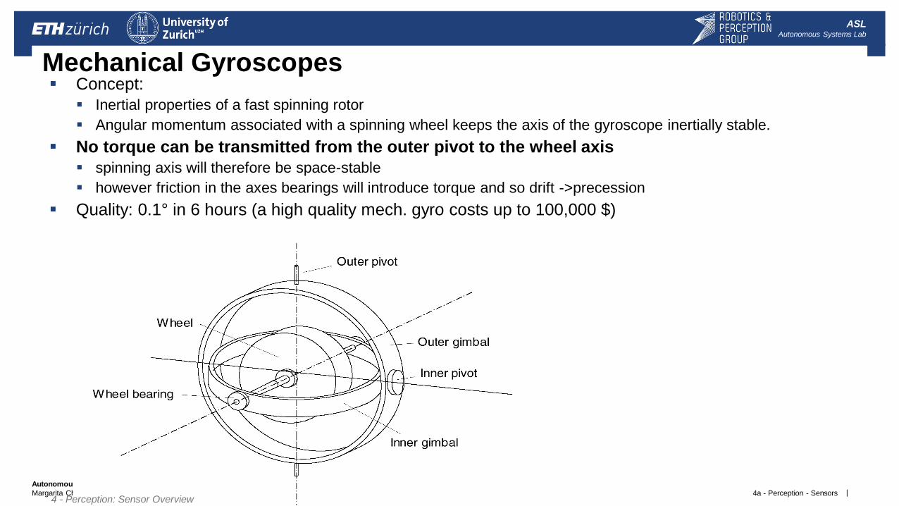
Mechanical Gyroscopes Concept:
Inertial properties of a fast spinning rotor
Angular momentum associated with a spinning wheel keeps the axis of the gyroscope inertially stable.
No torque can be transmitted from the outer pivot to the wheel axis
spinning axis will therefore be space-stable
however friction in the axes bearings will introduce torque and so drift ->precession
Quality: 0.1° in 6 hours (a high quality mech. gyro costs up to 100,000 $)
4 - Perception: Sensor Overview
| Autonomous Mobile Robots
Margarita Chli, Paul Furgale, Marco Hutter, Martin Rufli, Davide Scaramuzza, Roland Siegwart
ASL Autonomous Systems Lab
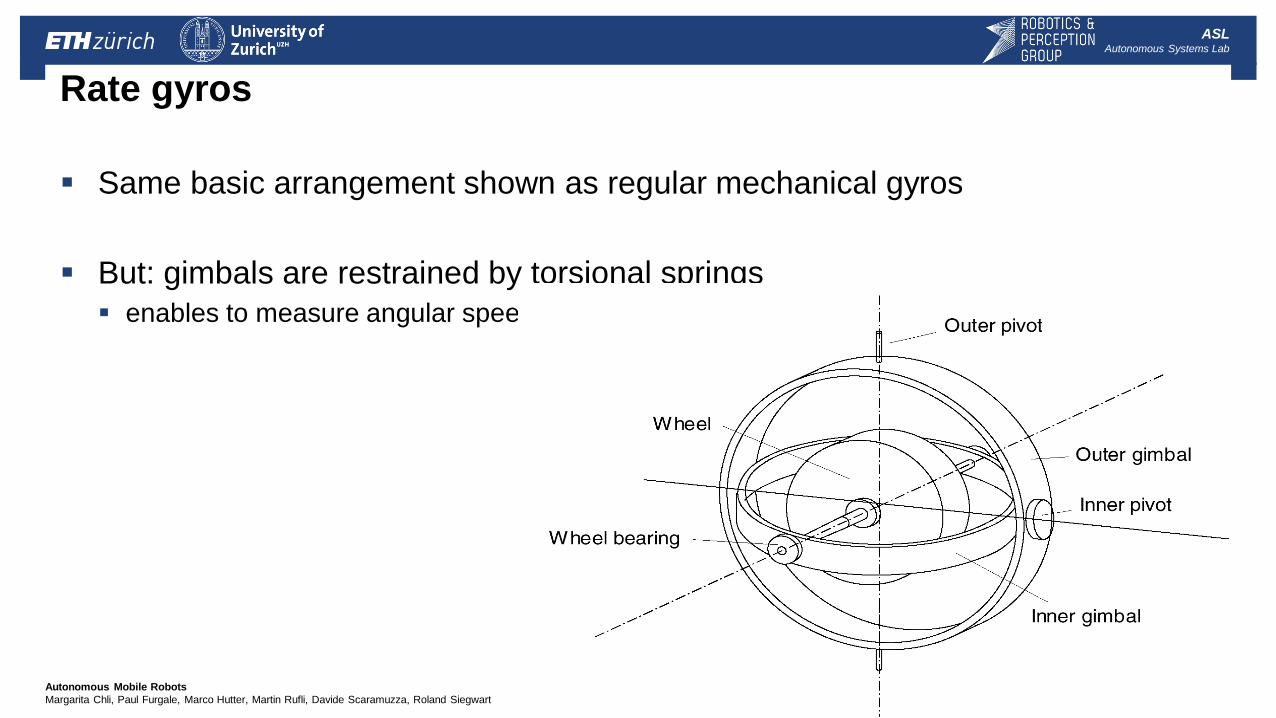
Rate gyros
Same basic arrangement shown as regular mechanical gyros
But: gimbals are restrained by torsional springs
enables to measure angular speeds instead of the orientation.
| Autonomous Mobile Robots
Margarita Chli, Paul Furgale, Marco Hutter, Martin Rufli, Davide Scaramuzza, Roland Siegwart
ASL Autonomous Systems Lab
Single axis optical gyro
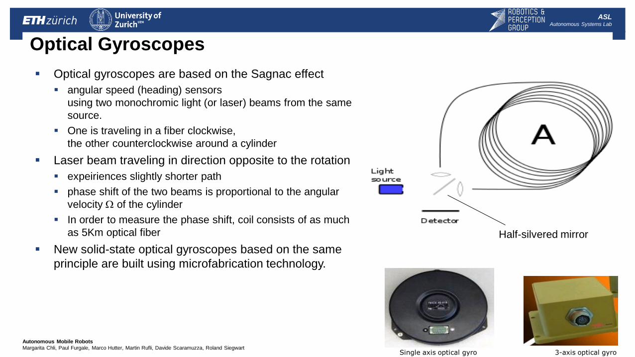
Optical Gyroscopes
Optical gyroscopes are based on the Sagnac effect
angular speed (heading) sensors
using two monochromic light (or laser) beams from the same
source.
One is traveling in a fiber clockwise,
the other counterclockwise around a cylinder
Laser beam traveling in direction opposite to the rotation
expeiriences slightly shorter path
phase shift of the two beams is proportional to the angular
velocity W of the cylinder
In order to measure the phase shift, coil consists of as much
as 5Km optical fiber
New solid-state optical gyroscopes based on the same
principle are built using microfabrication technology.
3-axis optical gyro
Half-silvered mirror
| Autonomous Mobile Robots
Margarita Chli, Paul Furgale, Marco Hutter, Martin Rufli, Davide Scaramuzza, Roland Siegwart
ASL Autonomous Systems Lab
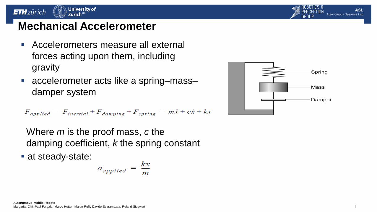
Mechanical Accelerometer
Accelerometers measure all external
forces acting upon them, including
gravity
accelerometer acts like a spring–mass–
damper system
Where m is the proof mass, c the
damping coefficient, k the spring constant
at steady-state:
| Autonomous Mobile Robots
Margarita Chli, Paul Furgale, Marco Hutter, Martin Rufli, Davide Scaramuzza, Roland Siegwart
ASL Autonomous Systems Lab
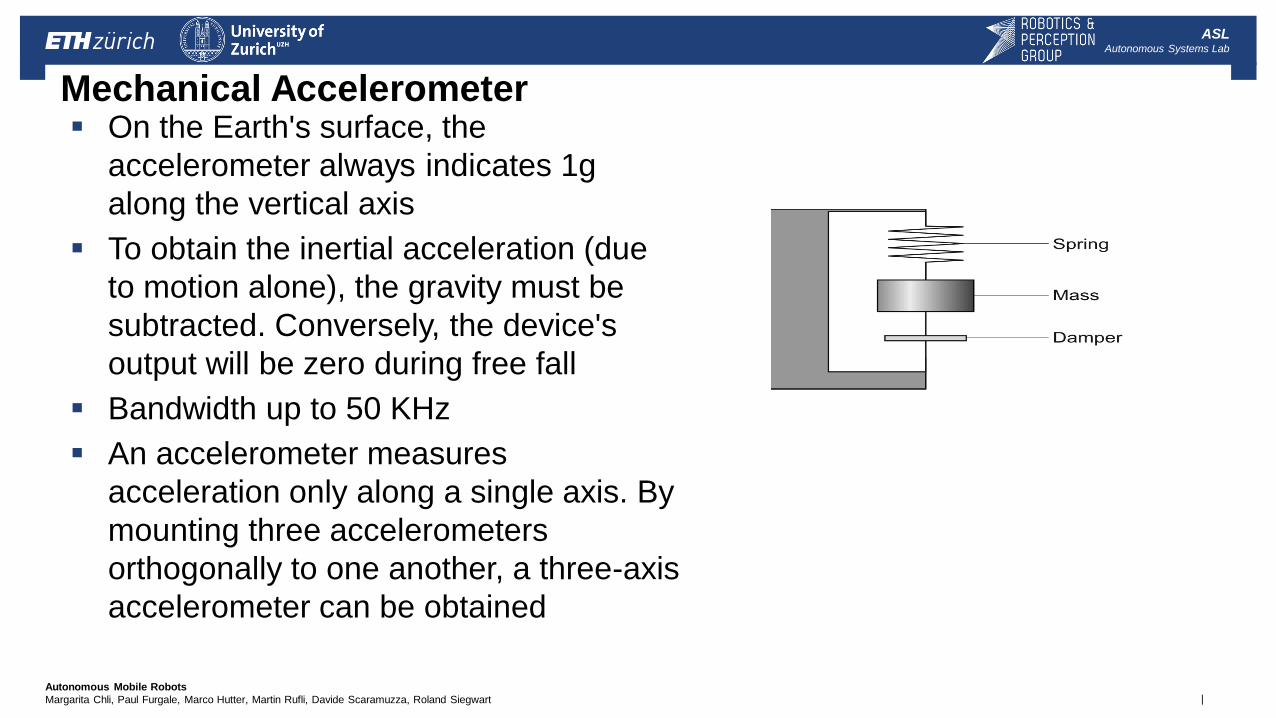
Mechanical Accelerometer On the Earth's surface, the
accelerometer always indicates 1g
along the vertical axis
To obtain the inertial acceleration (due
to motion alone), the gravity must be
subtracted. Conversely, the device's
output will be zero during free fall
Bandwidth up to 50 KHz
An accelerometer measures
acceleration only along a single axis. By
mounting three accelerometers
orthogonally to one another, a three-axis
accelerometer can be obtained
| Autonomous Mobile Robots
Margarita Chli, Paul Furgale, Marco Hutter, Martin Rufli, Davide Scaramuzza, Roland Siegwart
ASL Autonomous Systems Lab
Factsheet: MEMS Accelerometer (2)
spring
capacitive divider
M M M a a
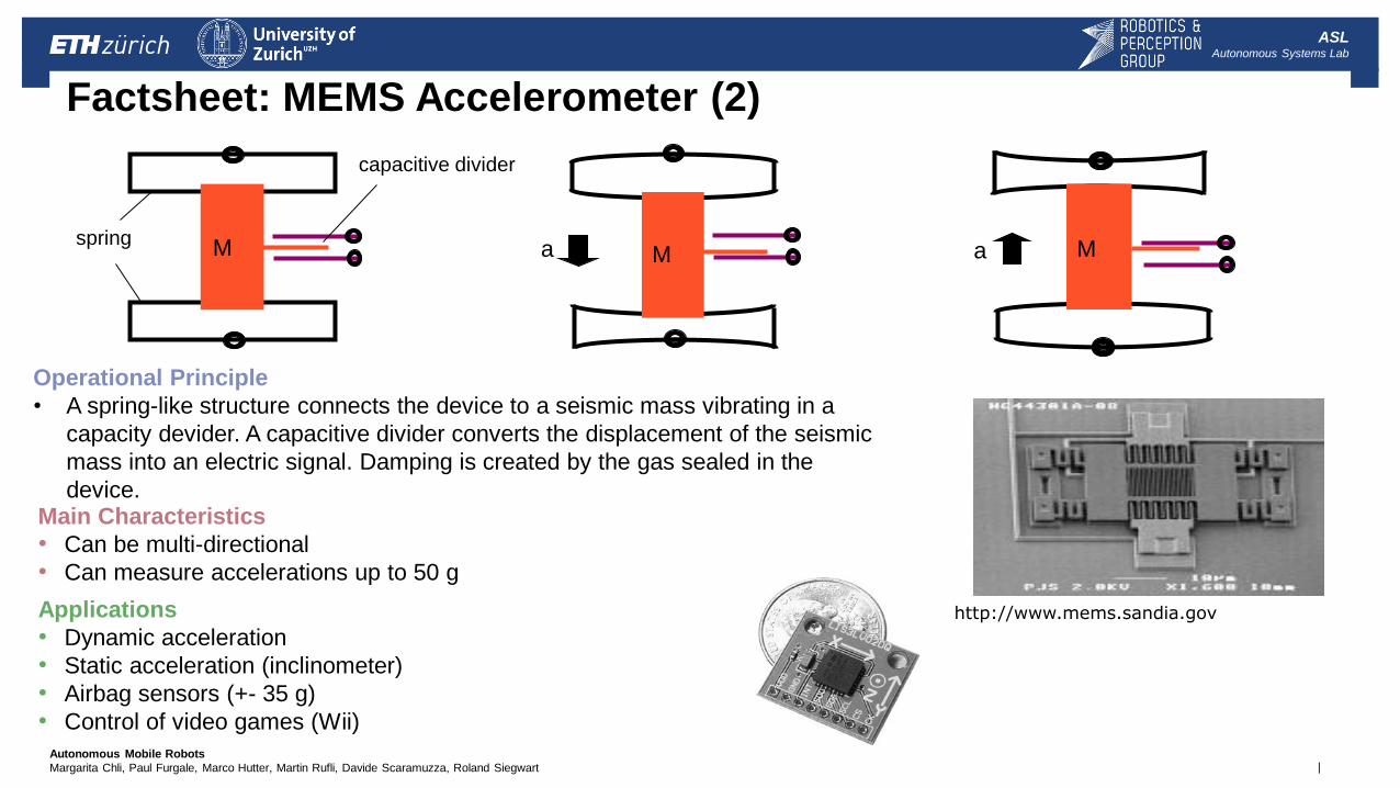
Applications
• Dynamic acceleration
• Static acceleration (inclinometer)
• Airbag sensors (+- 35 g)
• Control of video games (Wii)
Operational Principle
• A spring-like structure connects the device to a seismic mass vibrating in a
capacity devider. A capacitive divider converts the displacement of the seismic
mass into an electric signal. Damping is created by the gas sealed in the
device. Main Characteristics
• Can be multi-directional
• Can measure accelerations up to 50 g
http://www.mems.sandia.gov
| Autonomous Mobile Robots
Margarita Chli, Paul Furgale, Marco Hutter, Martin Rufli, Davide Scaramuzza, Roland Siegwart
ASL Autonomous Systems Lab
Factsheet: Piezoelectric Accelerometer
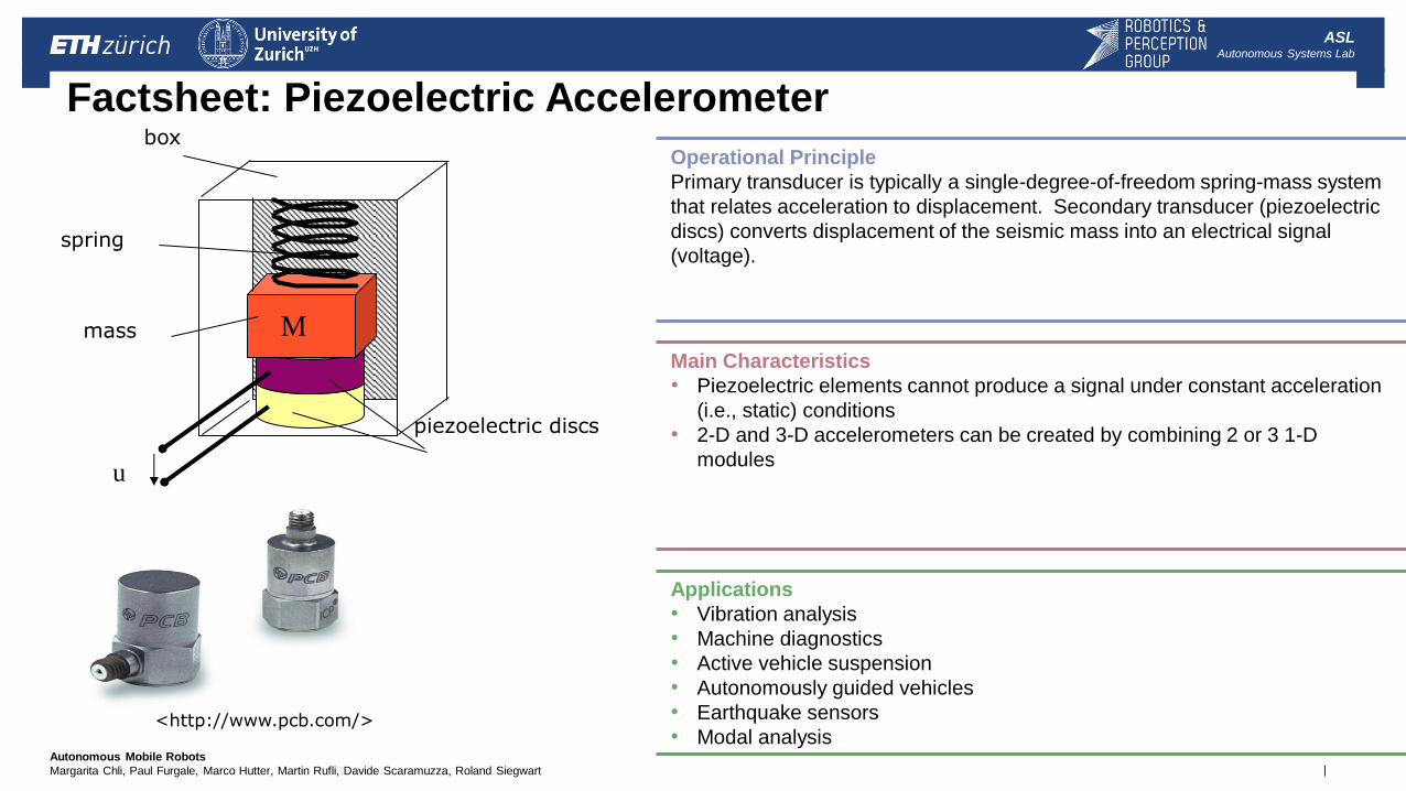
Operational Principle
Primary transducer is typically a single-degree-of-freedom spring-mass system
that relates acceleration to displacement. Secondary transducer (piezoelectric
discs) converts displacement of the seismic mass into an electrical signal
(voltage).
Main Characteristics
• Piezoelectric elements cannot produce a signal under constant acceleration
(i.e., static) conditions
• 2-D and 3-D accelerometers can be created by combining 2 or 3 1-D
modules
Applications
• Vibration analysis
• Machine diagnostics
• Active vehicle suspension
• Autonomously guided vehicles
• Earthquake sensors
• Modal analysis
M
box
spring
piezoelectric discs
mass
u
<http://www.pcb.com/>
| Autonomous Mobile Robots
Margarita Chli, Paul Furgale, Marco Hutter, Martin Rufli, Davide Scaramuzza, Roland Siegwart
ASL Autonomous Systems Lab
Inertial Measurement Unit (IMU)
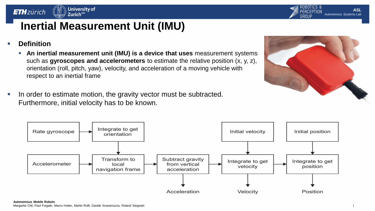
Definition
An inertial measurement unit (IMU) is a device that uses measurement systems
such as gyroscopes and accelerometers to estimate the relative position (x, y, z),
orientation (roll, pitch, yaw), velocity, and acceleration of a moving vehicle with
respect to an inertial frame
In order to estimate motion, the gravity vector must be subtracted.
Furthermore, initial velocity has to be known.
| Autonomous Mobile Robots
Margarita Chli, Paul Furgale, Marco Hutter, Martin Rufli, Davide Scaramuzza, Roland Siegwart
ASL Autonomous Systems Lab
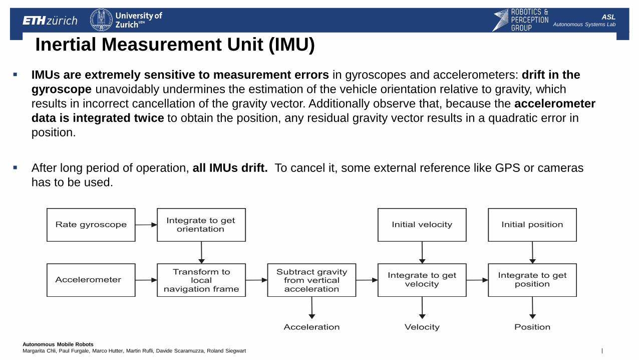
Inertial Measurement Unit (IMU)
IMUs are extremely sensitive to measurement errors in gyroscopes and accelerometers: drift in the
gyroscope unavoidably undermines the estimation of the vehicle orientation relative to gravity, which
results in incorrect cancellation of the gravity vector. Additionally observe that, because the accelerometer
data is integrated twice to obtain the position, any residual gravity vector results in a quadratic error in
position.
After long period of operation, all IMUs drift. To cancel it, some external reference like GPS or cameras
has to be used.
| Autonomous Mobile Robots
Margarita Chli, Paul Furgale, Marco Hutter, Martin Rufli, Davide Scaramuzza, Roland Siegwart
ASL Autonomous Systems Lab
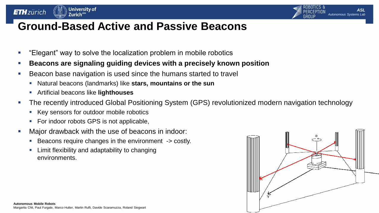
Ground-Based Active and Passive Beacons
“Elegant” way to solve the localization problem in mobile robotics
Beacons are signaling guiding devices with a precisely known position
Beacon base navigation is used since the humans started to travel
Natural beacons (landmarks) like stars, mountains or the sun
Artificial beacons like lighthouses
The recently introduced Global Positioning System (GPS) revolutionized modern navigation technology
Key sensors for outdoor mobile robotics
For indoor robots GPS is not applicable,
Major drawback with the use of beacons in indoor:
Beacons require changes in the environment -> costly.
Limit flexibility and adaptability to changing
environments.
| Autonomous Mobile Robots
Margarita Chli, Paul Furgale, Marco Hutter, Martin Rufli, Davide Scaramuzza, Roland Siegwart
ASL Autonomous Systems Lab
4 - Perception: Sensor Overview
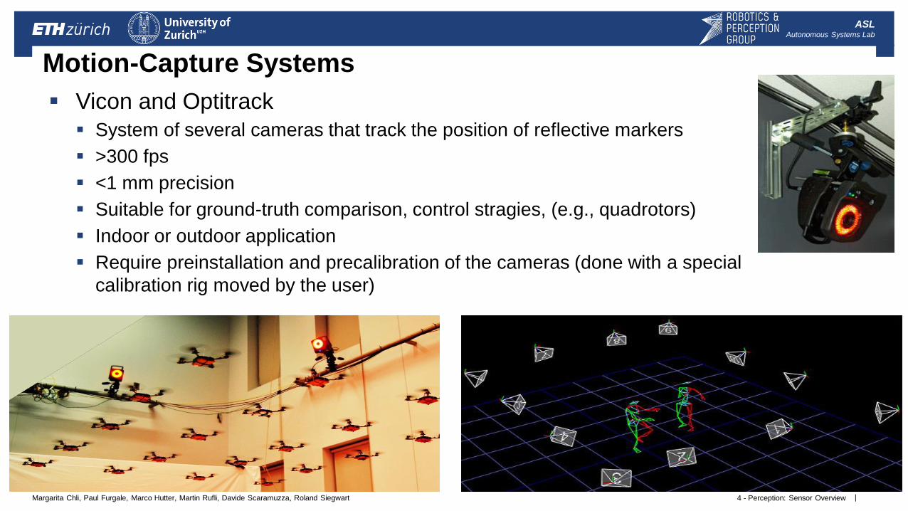
Motion-Capture Systems
Vicon and Optitrack
System of several cameras that track the position of reflective markers
>300 fps
<1 mm precision
Suitable for ground-truth comparison, control stragies, (e.g., quadrotors)
Indoor or outdoor application
Require preinstallation and precalibration of the cameras (done with a special
calibration rig moved by the user)
| Autonomous Mobile Robots
Margarita Chli, Paul Furgale, Marco Hutter, Martin Rufli, Davide Scaramuzza, Roland Siegwart
ASL Autonomous Systems Lab
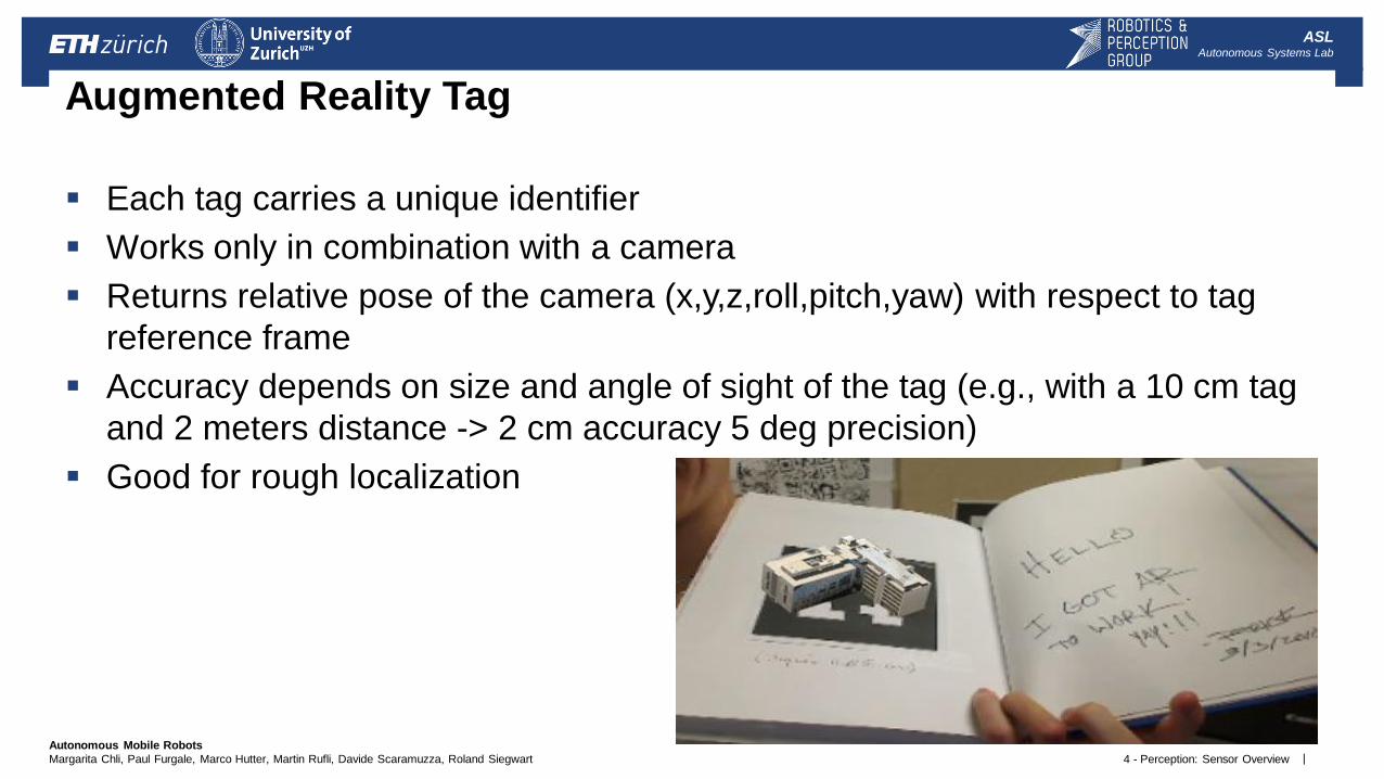
Each tag carries a unique identifier
Works only in combination with a camera
Returns relative pose of the camera (x,y,z,roll,pitch,yaw) with respect to tag
reference frame
Accuracy depends on size and angle of sight of the tag (e.g., with a 10 cm tag
and 2 meters distance -> 2 cm accuracy 5 deg precision)
Good for rough localization
4 - Perception: Sensor Overview
Augmented Reality Tag
| Autonomous Mobile Robots
Margarita Chli, Paul Furgale, Marco Hutter, Martin Rufli, Davide Scaramuzza, Roland Siegwart
ASL Autonomous Systems Lab
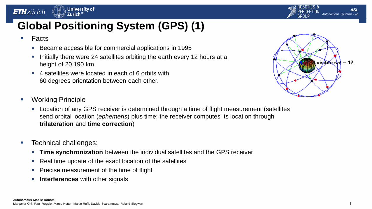
Global Positioning System (GPS) (1) Facts
Became accessible for commercial applications in 1995
Initially there were 24 satellites orbiting the earth every 12 hours at a
height of 20.190 km.
4 satellites were located in each of 6 orbits with
60 degrees orientation between each other.
Working Principle
Location of any GPS receiver is determined through a time of flight measurement (satellites
send orbital location (ephemeris) plus time; the receiver computes its location through
trilateration and time correction)
Technical challenges:
Time synchronization between the individual satellites and the GPS receiver
Real time update of the exact location of the satellites
Precise measurement of the time of flight
Interferences with other signals
| Autonomous Mobile Robots
Margarita Chli, Paul Furgale, Marco Hutter, Martin Rufli, Davide Scaramuzza, Roland Siegwart
ASL Autonomous Systems Lab
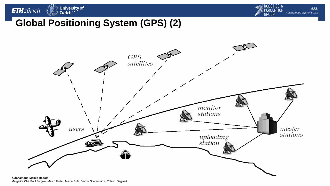
Global Positioning System (GPS) (2)
| Autonomous Mobile Robots
Margarita Chli, Paul Furgale, Marco Hutter, Martin Rufli, Davide Scaramuzza, Roland Siegwart
ASL Autonomous Systems Lab
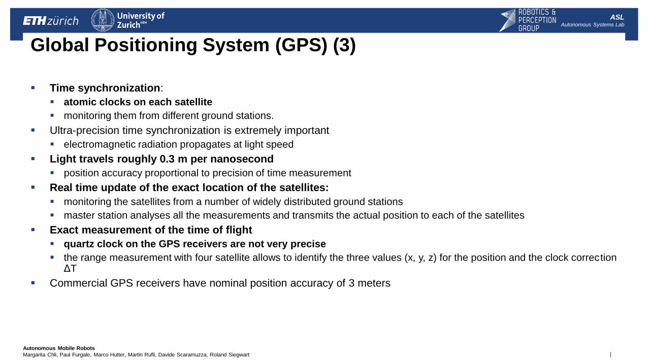
Global Positioning System (GPS) (3)
Time synchronization:
atomic clocks on each satellite
monitoring them from different ground stations.
Ultra-precision time synchronization is extremely important
electromagnetic radiation propagates at light speed
Light travels roughly 0.3 m per nanosecond
position accuracy proportional to precision of time measurement
Real time update of the exact location of the satellites:
monitoring the satellites from a number of widely distributed ground stations
master station analyses all the measurements and transmits the actual position to each of the satellites
Exact measurement of the time of flight
quartz clock on the GPS receivers are not very precise
the range measurement with four satellite allows to identify the three values (x, y, z) for the position and the clock correction ΔT
Commercial GPS receivers have nominal position accuracy of 3 meters
| Autonomous Mobile Robots
Margarita Chli, Paul Furgale, Marco Hutter, Martin Rufli, Davide Scaramuzza, Roland Siegwart
ASL Autonomous Systems Lab
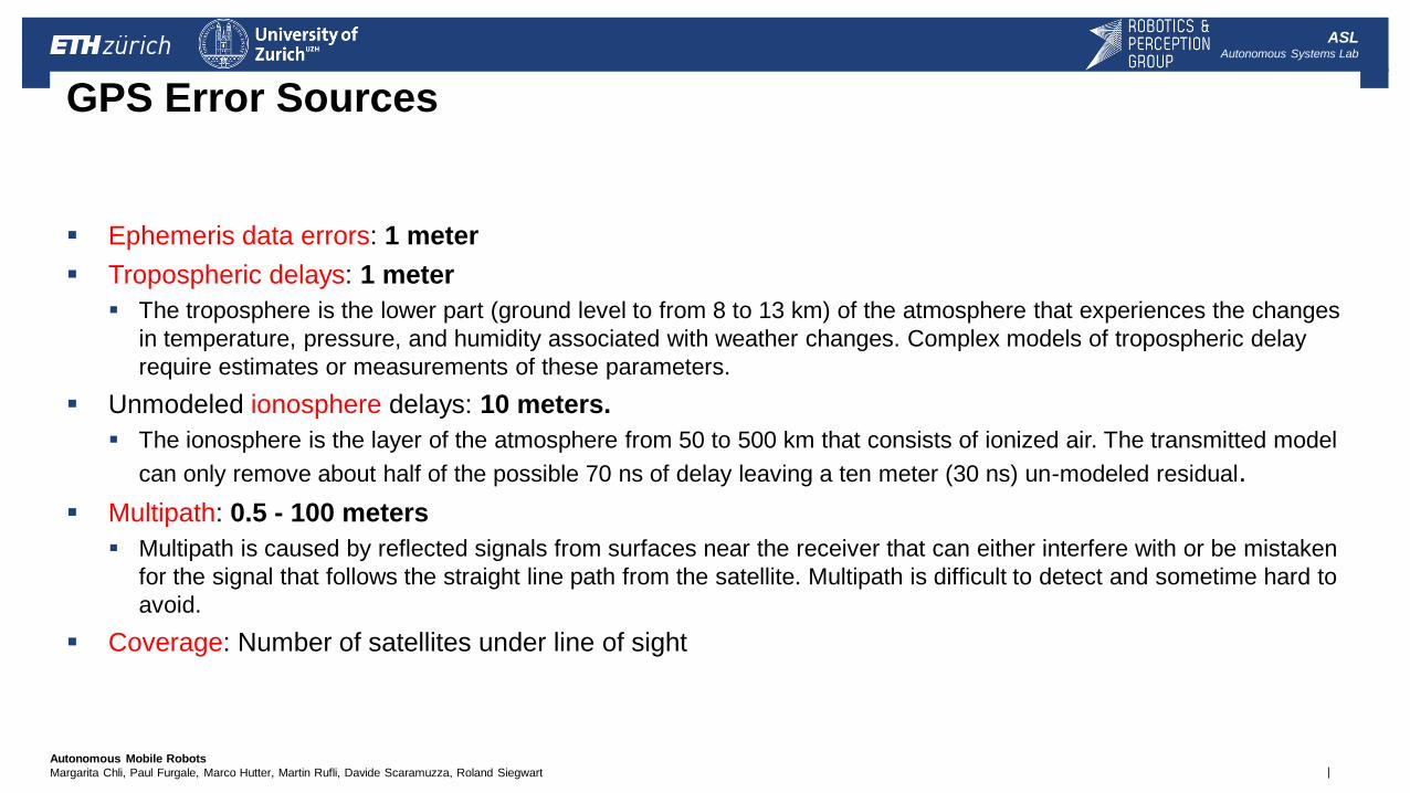
Ephemeris data errors: 1 meter
Tropospheric delays: 1 meter
The troposphere is the lower part (ground level to from 8 to 13 km) of the atmosphere that experiences the changes
in temperature, pressure, and humidity associated with weather changes. Complex models of tropospheric delay
require estimates or measurements of these parameters.
Unmodeled ionosphere delays: 10 meters.
The ionosphere is the layer of the atmosphere from 50 to 500 km that consists of ionized air. The transmitted model
can only remove about half of the possible 70 ns of delay leaving a ten meter (30 ns) un-modeled residual.
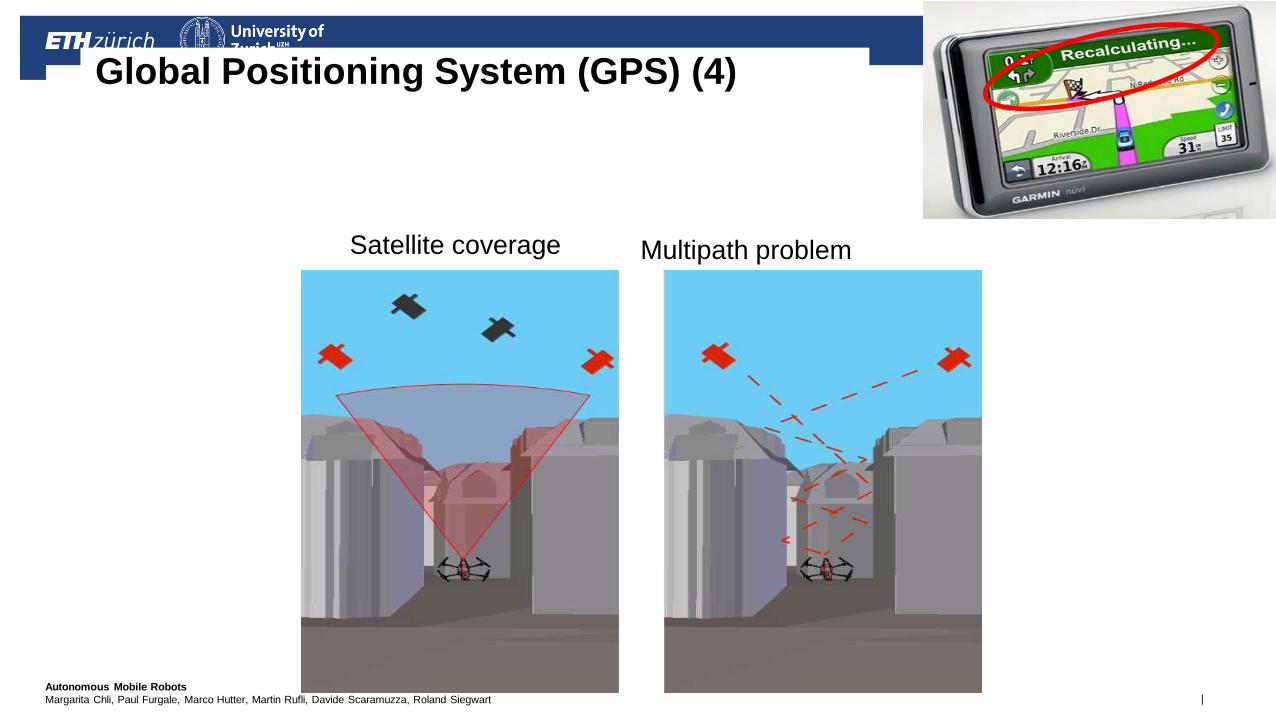
Multipath: 0.5 - 100 meters
Multipath is caused by reflected signals from surfaces near the receiver that can either interfere with or be mistaken
for the signal that follows the straight line path from the satellite. Multipath is difficult to detect and sometime hard to
avoid.
Coverage: Number of satellites under line of sight
GPS Error Sources
| Autonomous Mobile Robots
Margarita Chli, Paul Furgale, Marco Hutter, Martin Rufli, Davide Scaramuzza, Roland Siegwart
ASL Autonomous Systems Lab
Global Positioning System (GPS) (4)
Satellite coverage Multipath problem
| Autonomous Mobile Robots
Margarita Chli, Paul Furgale, Marco Hutter, Martin Rufli, Davide Scaramuzza, Roland Siegwart
ASL Autonomous Systems Lab
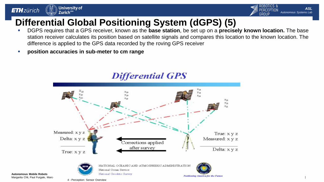
Differential Global Positioning System (dGPS) (5) DGPS requires that a GPS receiver, known as the base station, be set up on a precisely known location. The base
station receiver calculates its position based on satellite signals and compares this location to the known location. The
difference is applied to the GPS data recorded by the roving GPS receiver
position accuracies in sub-meter to cm range
4 - Perception: Sensor Overview
| Autonomous Mobile Robots
Margarita Chli, Paul Furgale, Marco Hutter, Martin Rufli, Davide Scaramuzza, Roland Siegwart
ASL Autonomous Systems Lab
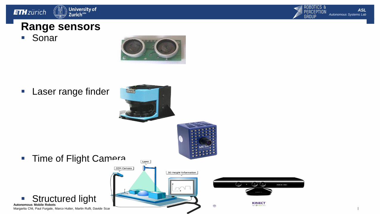
Range sensors Sonar
Laser range finder
Time of Flight Camera
Structured light
| Autonomous Mobile Robots
Margarita Chli, Paul Furgale, Marco Hutter, Martin Rufli, Davide Scaramuzza, Roland Siegwart
ASL Autonomous Systems Lab
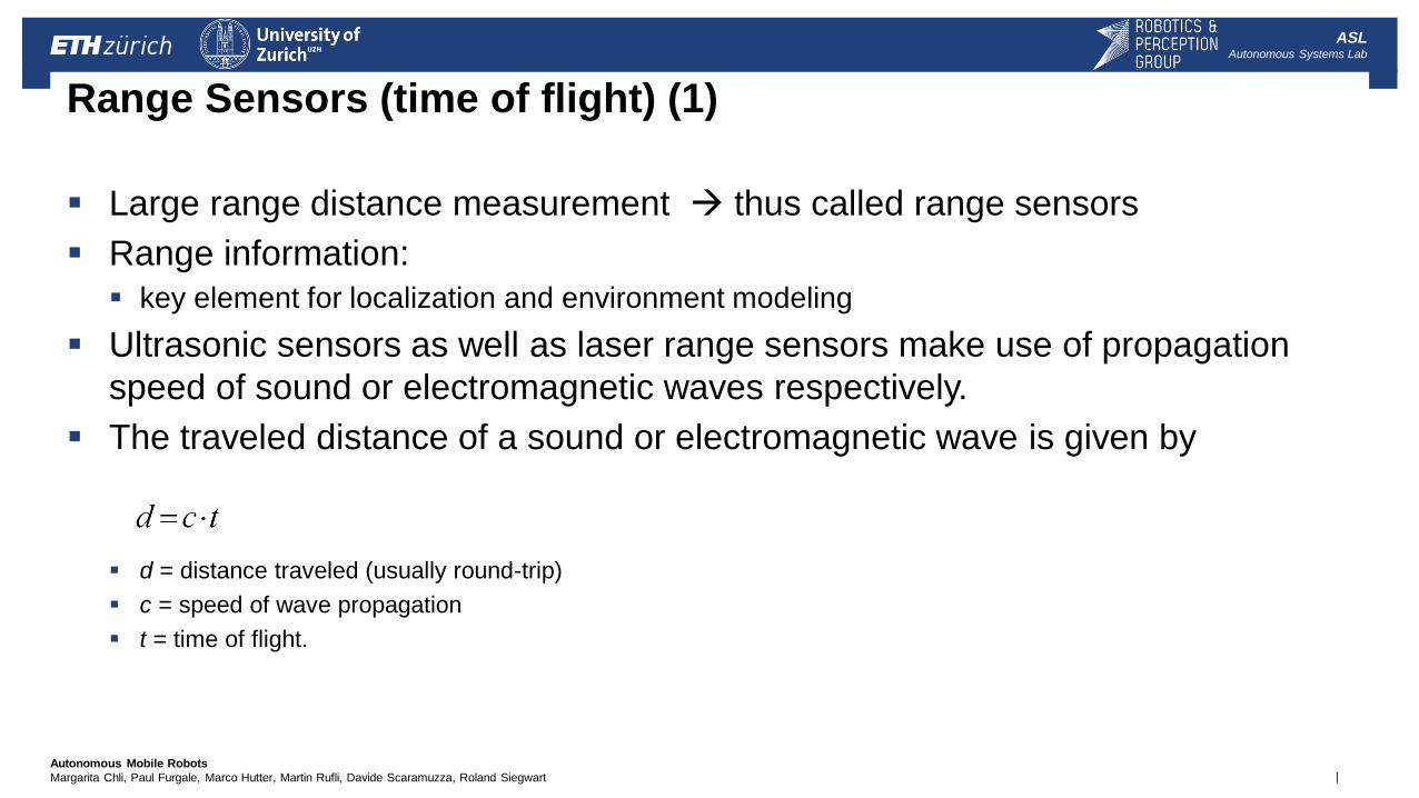
Range Sensors (time of flight) (1)
Large range distance measurement thus called range sensors
Range information:
key element for localization and environment modeling
Ultrasonic sensors as well as laser range sensors make use of propagation
speed of sound or electromagnetic waves respectively.
The traveled distance of a sound or electromagnetic wave is given by
d = distance traveled (usually round-trip)
c = speed of wave propagation
t = time of flight.
| Autonomous Mobile Robots
Margarita Chli, Paul Furgale, Marco Hutter, Martin Rufli, Davide Scaramuzza, Roland Siegwart
ASL Autonomous Systems Lab
Range Sensors (time of flight) (2)
It is important to point out
Propagation speed of sound: 0.3 m/ms
Propagation speed of of electromagnetic signals: 0.3 m/ns,
Electromagnetic signals travel one million times faster.
3 meters
Equivalent to 10 ms for an ultrasonic system
Equivalent to only 10 ns for a laser range sensor
Measuring time of flight with electromagnetic signals is not an easy task
laser range sensors expensive and delicate
The quality of time of flight range sensors mainly depends on:
Inaccuracies in the time of fight measurement (laser range sensors)
Opening angle of transmitted beam (especially ultrasonic range sensors)
Interaction with the target (surface, specular reflections)
Variation of propagation speed (sound)
Speed of mobile robot and target (if not at stand still)
| Autonomous Mobile Robots
Margarita Chli, Paul Furgale, Marco Hutter, Martin Rufli, Davide Scaramuzza, Roland Siegwart
ASL Autonomous Systems Lab
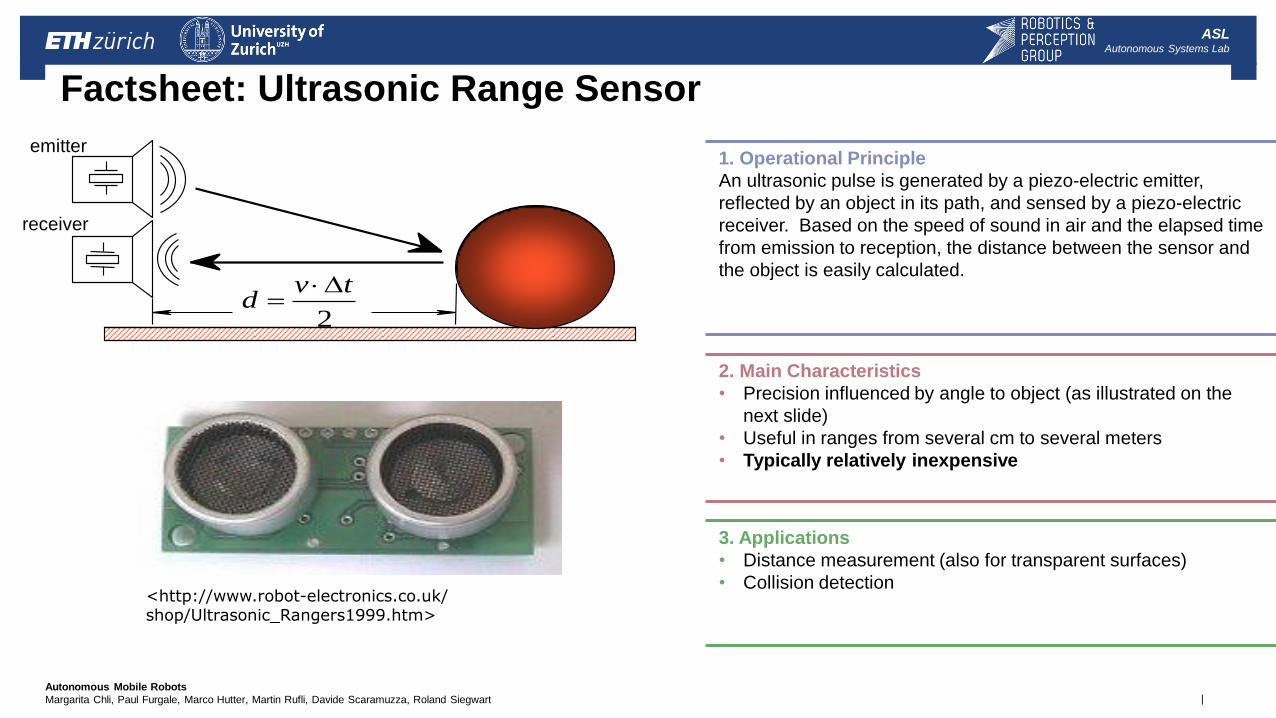
Factsheet: Ultrasonic Range Sensor
1. Operational Principle
An ultrasonic pulse is generated by a piezo-electric emitter,
reflected by an object in its path, and sensed by a piezo-electric
receiver. Based on the speed of sound in air and the elapsed time
from emission to reception, the distance between the sensor and
the object is easily calculated.
2. Main Characteristics
• Precision influenced by angle to object (as illustrated on the
next slide)
• Useful in ranges from several cm to several meters
• Typically relatively inexpensive
3. Applications
• Distance measurement (also for transparent surfaces)
• Collision detection
emitter
receiver
2
tvd
<http://www.robot-electronics.co.uk/ shop/Ultrasonic_Rangers1999.htm>
| Autonomous Mobile Robots
Margarita Chli, Paul Furgale, Marco Hutter, Martin Rufli, Davide Scaramuzza, Roland Siegwart
ASL Autonomous Systems Lab
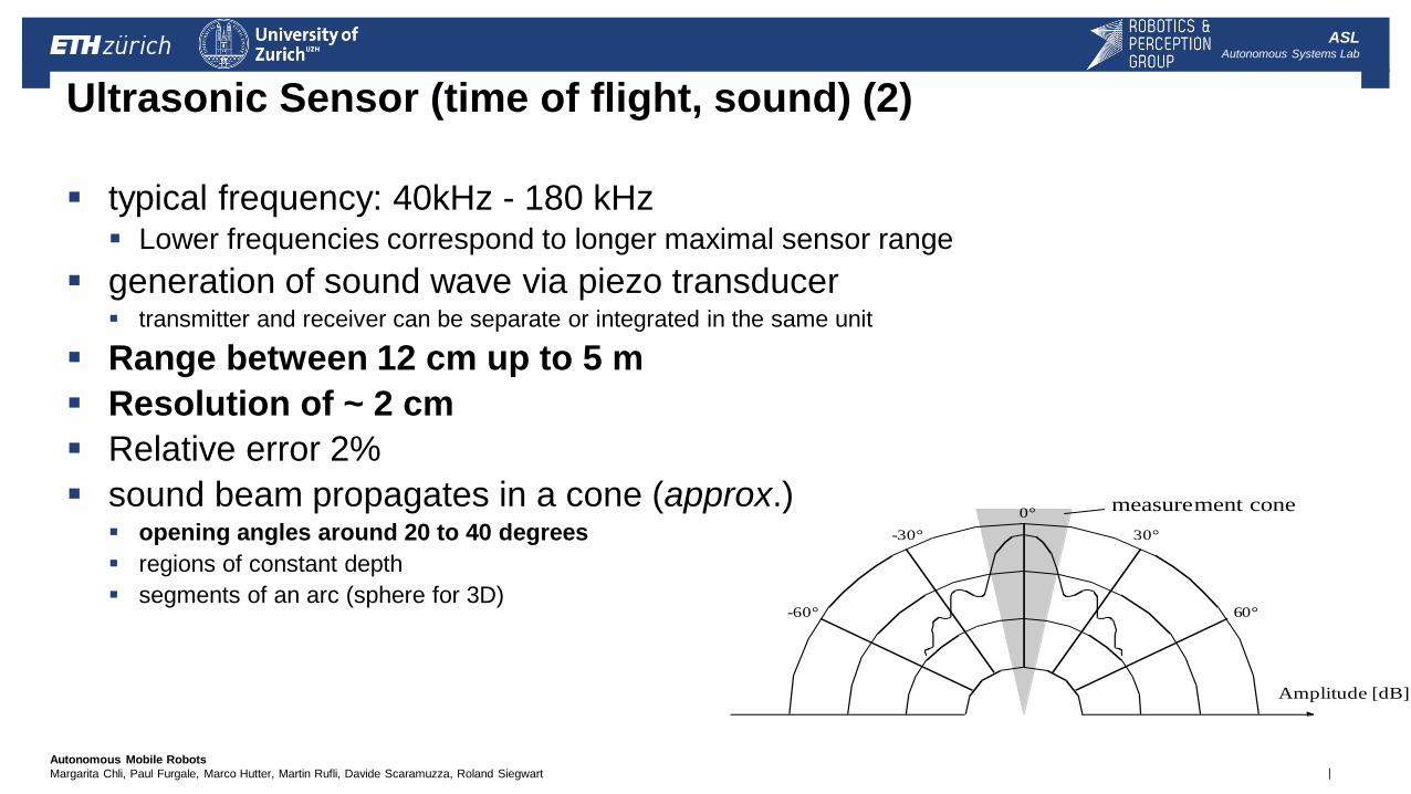
Ultrasonic Sensor (time of flight, sound) (2)
typical frequency: 40kHz - 180 kHz Lower frequencies correspond to longer maximal sensor range
generation of sound wave via piezo transducer transmitter and receiver can be separate or integrated in the same unit
Range between 12 cm up to 5 m
Resolution of ~ 2 cm
Relative error 2%
sound beam propagates in a cone (approx.) opening angles around 20 to 40 degrees
regions of constant depth
segments of an arc (sphere for 3D)
Typical intensity distribution of a ultrasonic sensor
-30°
-60°
0°
30°
60°
Amplitude [dB]
measurement cone
| Autonomous Mobile Robots
Margarita Chli, Paul Furgale, Marco Hutter, Martin Rufli, Davide Scaramuzza, Roland Siegwart
ASL Autonomous Systems Lab
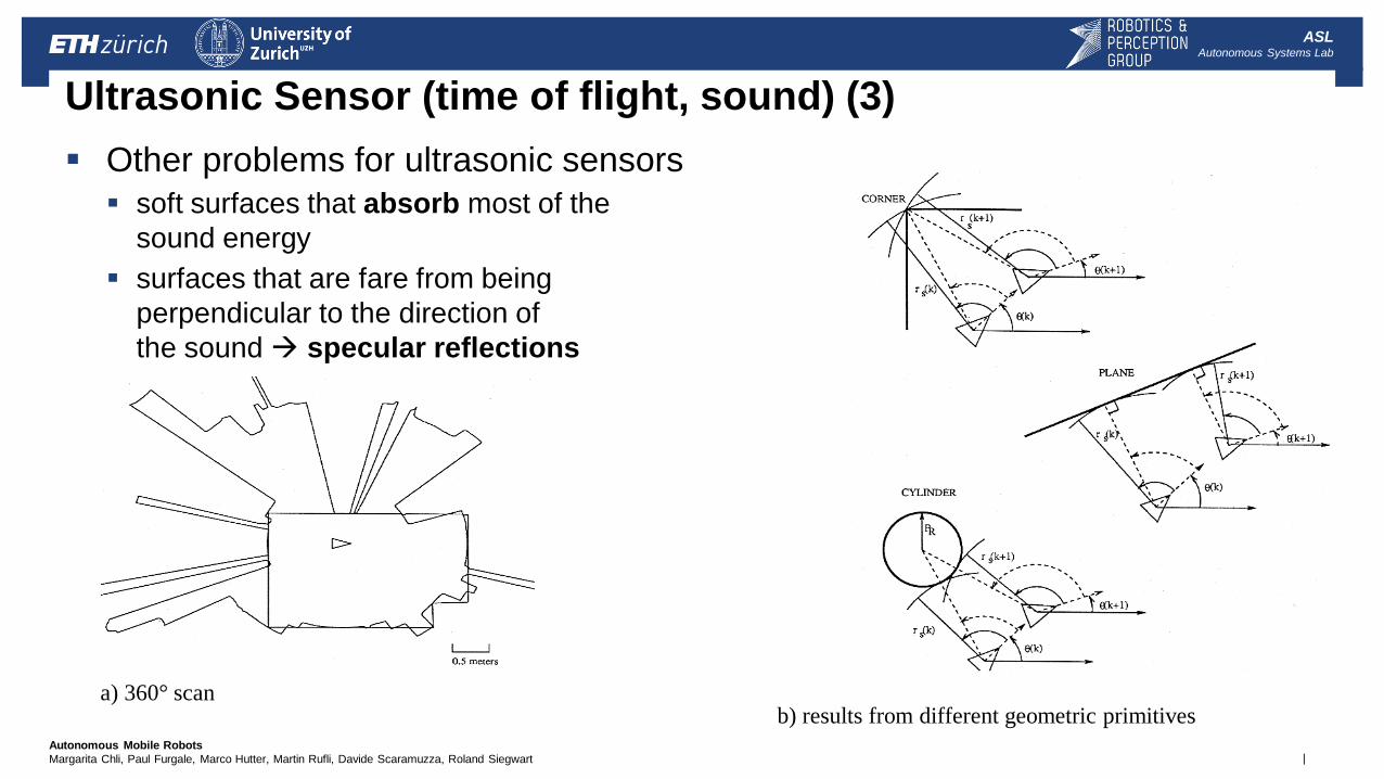
Ultrasonic Sensor (time of flight, sound) (3)
Other problems for ultrasonic sensors
soft surfaces that absorb most of the
sound energy
surfaces that are fare from being
perpendicular to the direction of
the sound specular reflections
a) 360° scan b) results from different geometric primitives
| Autonomous Mobile Robots
Margarita Chli, Paul Furgale, Marco Hutter, Martin Rufli, Davide Scaramuzza, Roland Siegwart
ASL Autonomous Systems Lab
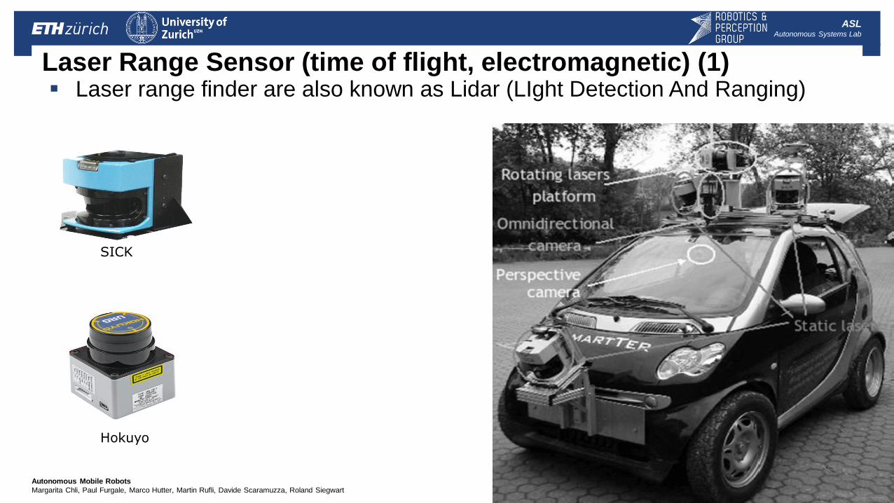
Laser Range Sensor (time of flight, electromagnetic) (1) Laser range finder are also known as Lidar (LIght Detection And Ranging)
SICK
Hokuyo
| Autonomous Mobile Robots
Margarita Chli, Paul Furgale, Marco Hutter, Martin Rufli, Davide Scaramuzza, Roland Siegwart
ASL Autonomous Systems Lab
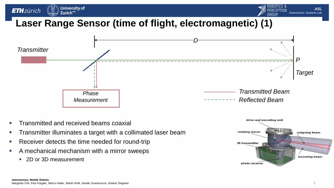
Laser Range Sensor (time of flight, electromagnetic) (1)
Transmitted and received beams coaxial
Transmitter illuminates a target with a collimated laser beam
Receiver detects the time needed for round-trip
A mechanical mechanism with a mirror sweeps
2D or 3D measurement
Phase
Measurement
Target
Transmitter
Transmitted Beam
Reflected Beam
P
D
| Autonomous Mobile Robots
Margarita Chli, Paul Furgale, Marco Hutter, Martin Rufli, Davide Scaramuzza, Roland Siegwart
ASL Autonomous Systems Lab
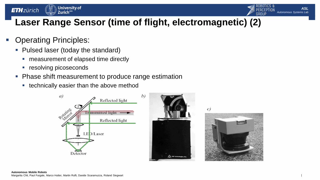
Laser Range Sensor (time of flight, electromagnetic) (2)
Operating Principles:
Pulsed laser (today the standard)
measurement of elapsed time directly
resolving picoseconds
Phase shift measurement to produce range estimation
technically easier than the above method
| Autonomous Mobile Robots
Margarita Chli, Paul Furgale, Marco Hutter, Martin Rufli, Davide Scaramuzza, Roland Siegwart
ASL Autonomous Systems Lab
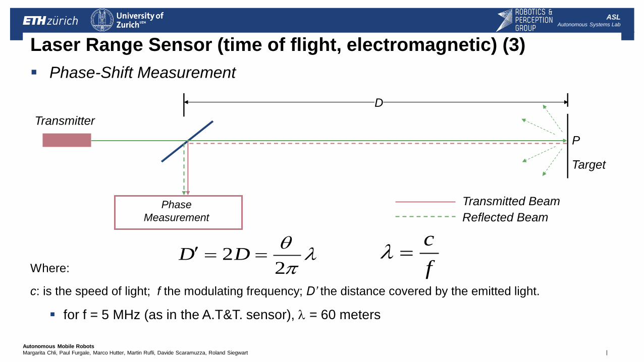
Laser Range Sensor (time of flight, electromagnetic) (3)
Phase-Shift Measurement
Where:
c: is the speed of light; f the modulating frequency; D’ the distance covered by the emitted light.
for f = 5 MHz (as in the A.T&T. sensor), l = 60 meters
l
22 DD
f
cl
Phase
Measurement
Target
Transmitter
Transmitted Beam
Reflected Beam
P
D
| Autonomous Mobile Robots
Margarita Chli, Paul Furgale, Marco Hutter, Martin Rufli, Davide Scaramuzza, Roland Siegwart
ASL Autonomous Systems Lab
Laser Range Sensor (time of flight, electromagnetic) (4)
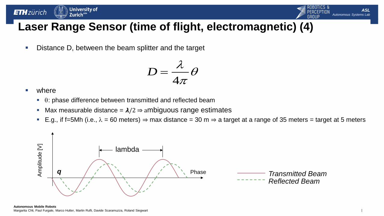
Distance D, between the beam splitter and the target
where
: phase difference between transmitted and reflected beam
Max measurable distance = 𝞴/2 ⇒ ambiguous range estimates
E.g., if f=5Mh (i.e., l = 60 meters) ⇒ max distance = 30 m ⇒ a target at a range of 35 meters = target at 5 meters
l
4D
Am
plit
ude
[V
]
q Phase
lambda
Transmitted Beam Reflected Beam
| Autonomous Mobile Robots
Margarita Chli, Paul Furgale, Marco Hutter, Martin Rufli, Davide Scaramuzza, Roland Siegwart
ASL Autonomous Systems Lab
Laser Range Sensor (time of flight, electromagnetic) (5)
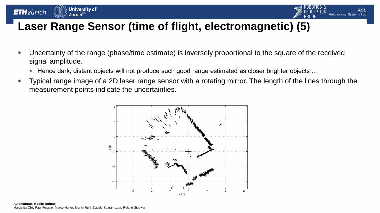
Uncertainty of the range (phase/time estimate) is inversely proportional to the square of the received
signal amplitude.
Hence dark, distant objects will not produce such good range estimated as closer brighter objects …
Typical range image of a 2D laser range sensor with a rotating mirror. The length of the lines through the
measurement points indicate the uncertainties.
| Autonomous Mobile Robots
Margarita Chli, Paul Furgale, Marco Hutter, Martin Rufli, Davide Scaramuzza, Roland Siegwart
ASL Autonomous Systems Lab
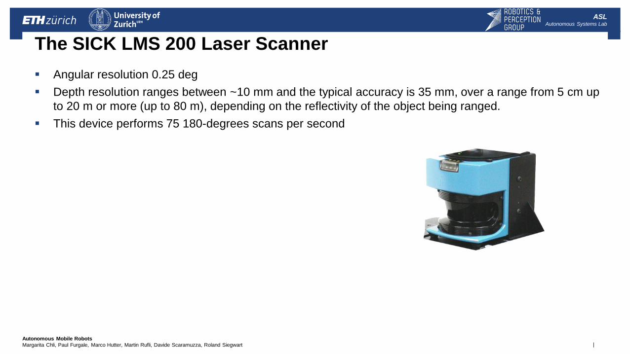
The SICK LMS 200 Laser Scanner
Angular resolution 0.25 deg
Depth resolution ranges between ~10 mm and the typical accuracy is 35 mm, over a range from 5 cm up
to 20 m or more (up to 80 m), depending on the reflectivity of the object being ranged.
This device performs 75 180-degrees scans per second
| Autonomous Mobile Robots
Margarita Chli, Paul Furgale, Marco Hutter, Martin Rufli, Davide Scaramuzza, Roland Siegwart
ASL Autonomous Systems Lab
3D Laser Range Finder (1)
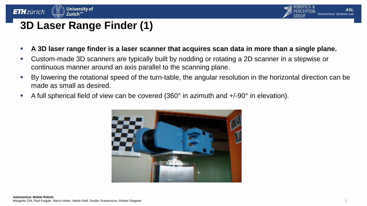
A 3D laser range finder is a laser scanner that acquires scan data in more than a single plane.
Custom-made 3D scanners are typically built by nodding or rotating a 2D scanner in a stepwise or
continuous manner around an axis parallel to the scanning plane.
By lowering the rotational speed of the turn-table, the angular resolution in the horizontal direction can be
made as small as desired.
A full spherical field of view can be covered (360° in azimuth and +/-90° in elevation).
| Autonomous Mobile Robots
Margarita Chli, Paul Furgale, Marco Hutter, Martin Rufli, Davide Scaramuzza, Roland Siegwart
ASL Autonomous Systems Lab
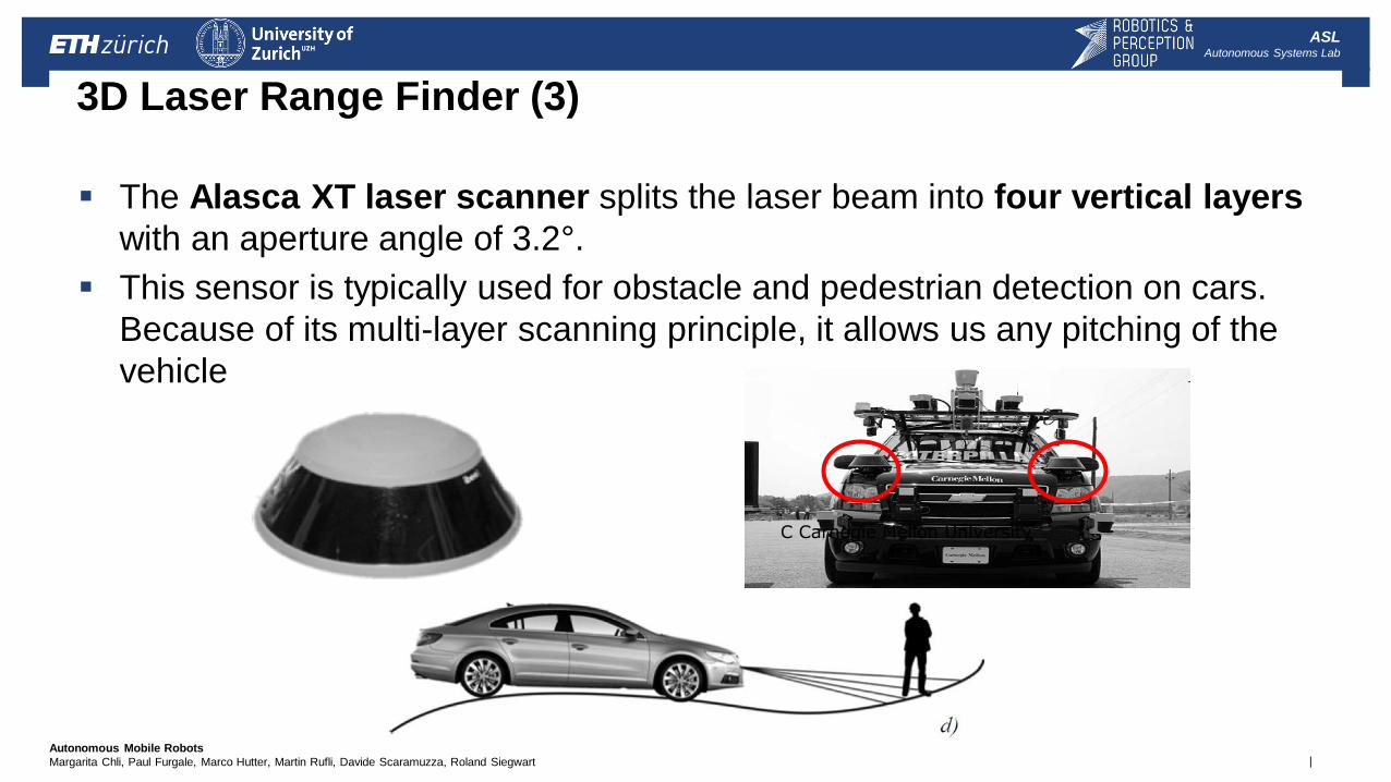
3D Laser Range Finder (3)
The Alasca XT laser scanner splits the laser beam into four vertical layers
with an aperture angle of 3.2°.
This sensor is typically used for obstacle and pedestrian detection on cars.
Because of its multi-layer scanning principle, it allows us any pitching of the
vehicle
C Carnegie Mellon University
| Autonomous Mobile Robots
Margarita Chli, Paul Furgale, Marco Hutter, Martin Rufli, Davide Scaramuzza, Roland Siegwart
ASL Autonomous Systems Lab
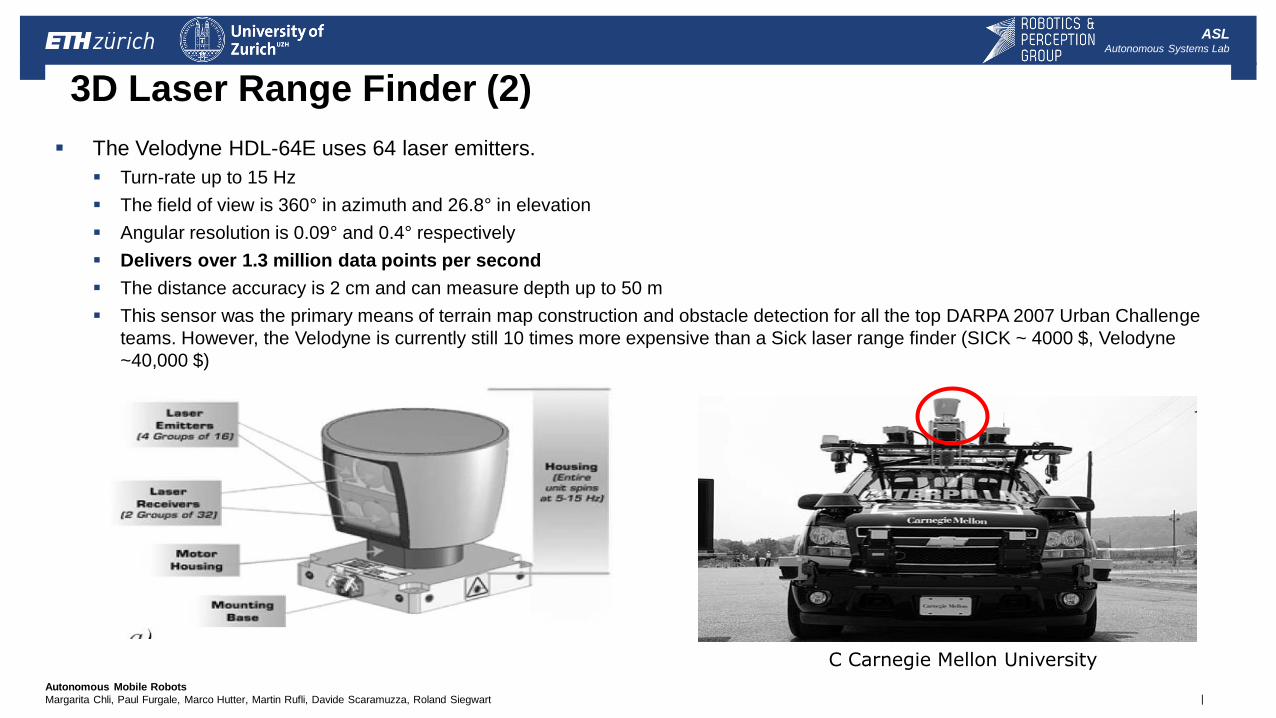
3D Laser Range Finder (2)
The Velodyne HDL-64E uses 64 laser emitters.
Turn-rate up to 15 Hz
The field of view is 360° in azimuth and 26.8° in elevation
Angular resolution is 0.09° and 0.4° respectively
Delivers over 1.3 million data points per second
The distance accuracy is 2 cm and can measure depth up to 50 m
This sensor was the primary means of terrain map construction and obstacle detection for all the top DARPA 2007 Urban Challenge
teams. However, the Velodyne is currently still 10 times more expensive than a Sick laser range finder (SICK ~ 4000 $, Velodyne
~40,000 $)
C Carnegie Mellon University
| Autonomous Mobile Robots
Margarita Chli, Paul Furgale, Marco Hutter, Martin Rufli, Davide Scaramuzza, Roland Siegwart
ASL Autonomous Systems Lab
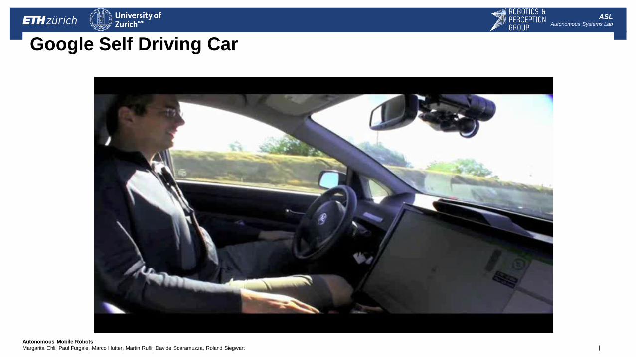
Google Self Driving Car
| Autonomous Mobile Robots
Margarita Chli, Paul Furgale, Marco Hutter, Martin Rufli, Davide Scaramuzza, Roland Siegwart
ASL Autonomous Systems Lab
Triangulation Sensor
Use of geometrical properties of the image to establish a distance measurement
If a well defined light pattern (e.g. point, line) is projected onto the environment.
reflected light is then captured by a photo-sensitive line or matrix (camera) sensor device
simple triangulation allows us to establish a distance.
If size of a captured object is precisely known
triangulation without light projecting
| Autonomous Mobile Robots
Margarita Chli, Paul Furgale, Marco Hutter, Martin Rufli, Davide Scaramuzza, Roland Siegwart
ASL Autonomous Systems Lab
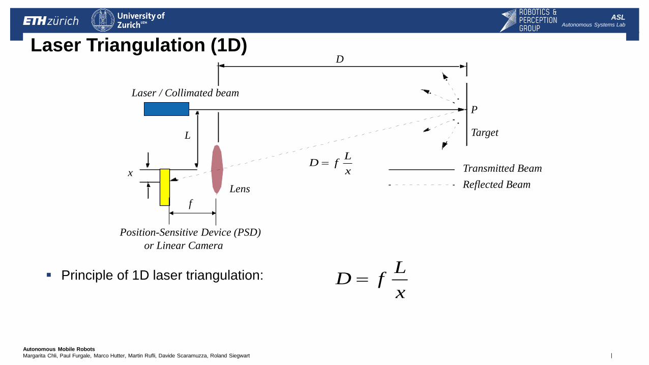
Laser Triangulation (1D)
Principle of 1D laser triangulation:
x
LfD
Target
D
L
Laser / Collimated beam
Transmitted Beam
Reflected Beam
P
Position-Sensitive Device (PSD)
or Linear Camera
x
Lens
x
LfD
f
| Autonomous Mobile Robots
Margarita Chli, Paul Furgale, Marco Hutter, Martin Rufli, Davide Scaramuzza, Roland Siegwart
ASL Autonomous Systems Lab
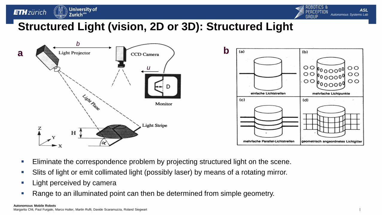
Structured Light (vision, 2D or 3D): Structured Light
Eliminate the correspondence problem by projecting structured light on the scene.
Slits of light or emit collimated light (possibly laser) by means of a rotating mirror.
Light perceived by camera
Range to an illuminated point can then be determined from simple geometry.
b
u
a b
| Autonomous Mobile Robots
Margarita Chli, Paul Furgale, Marco Hutter, Martin Rufli, Davide Scaramuzza, Roland Siegwart
ASL Autonomous Systems Lab
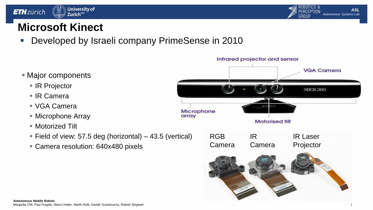
Microsoft Kinect
Developed by Israeli company PrimeSense in 2010
RGB
Camera
IR
Camera
IR Laser
Projector
Major components
IR Projector
IR Camera
VGA Camera
Microphone Array
Motorized Tilt
Field of view: 57.5 deg (horizontal) – 43.5 (vertical)
Camera resolution: 640x480 pixels
| Autonomous Mobile Robots
Margarita Chli, Paul Furgale, Marco Hutter, Martin Rufli, Davide Scaramuzza, Roland Siegwart
ASL Autonomous Systems Lab
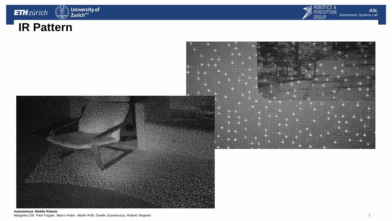
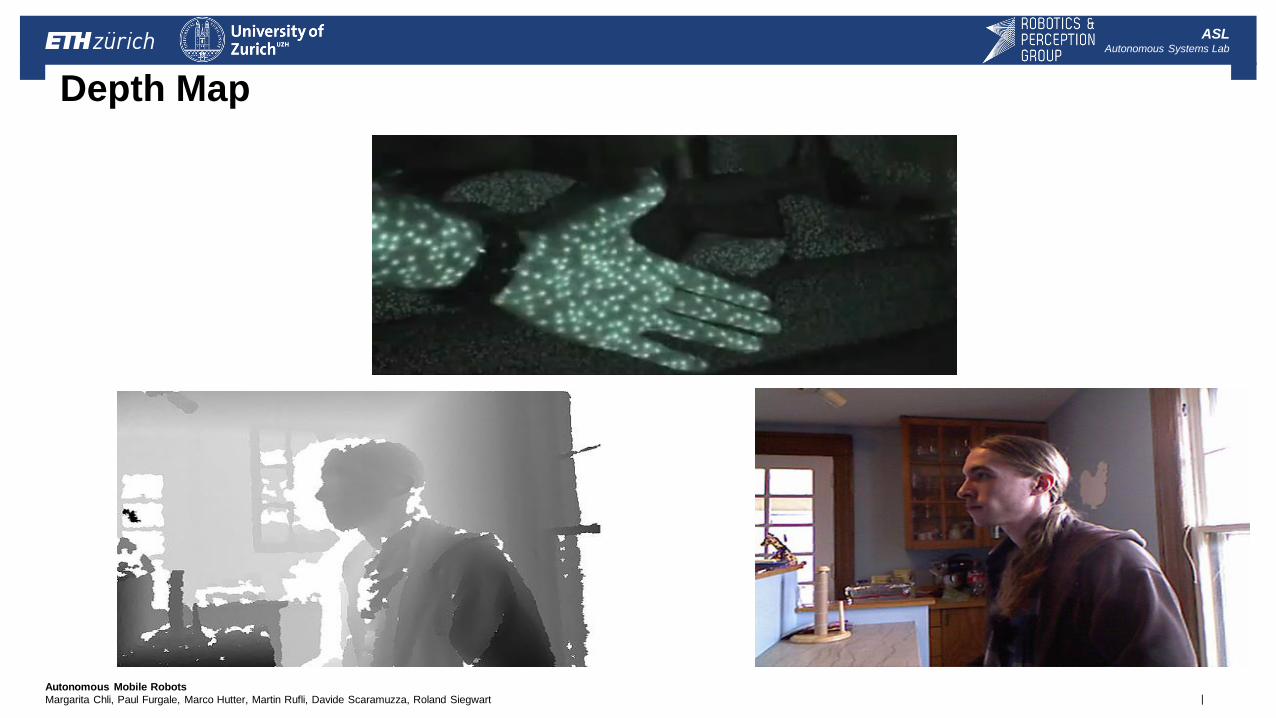
IR Pattern
| Autonomous Mobile Robots
Margarita Chli, Paul Furgale, Marco Hutter, Martin Rufli, Davide Scaramuzza, Roland Siegwart
ASL Autonomous Systems Lab
Depth Map

| Autonomous Mobile Robots
Margarita Chli, Paul Furgale, Marco Hutter, Martin Rufli, Davide Scaramuzza, Roland Siegwart
ASL Autonomous Systems Lab
Video Out
30 fps 57 degree 8 bit VGA RGB 640x480
| Autonomous Mobile Robots
Margarita Chli, Paul Furgale, Marco Hutter, Martin Rufli, Davide Scaramuzza, Roland Siegwart
ASL Autonomous Systems Lab
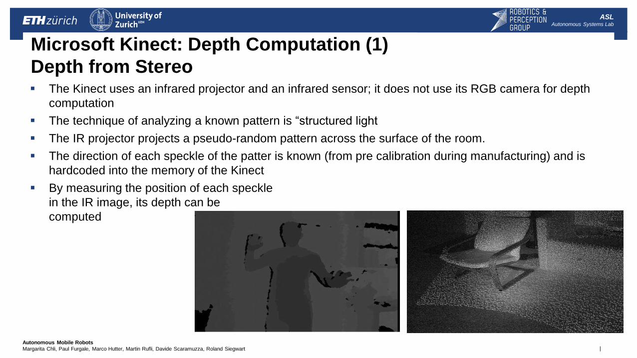
Microsoft Kinect: Depth Computation (1)
Depth from Stereo The Kinect uses an infrared projector and an infrared sensor; it does not use its RGB camera for depth
computation
The technique of analyzing a known pattern is “structured light
The IR projector projects a pseudo-random pattern across the surface of the room.
The direction of each speckle of the patter is known (from pre calibration during manufacturing) and is
hardcoded into the memory of the Kinect
By measuring the position of each speckle
in the IR image, its depth can be
computed
| Autonomous Mobile Robots
Margarita Chli, Paul Furgale, Marco Hutter, Martin Rufli, Davide Scaramuzza, Roland Siegwart
ASL Autonomous Systems Lab
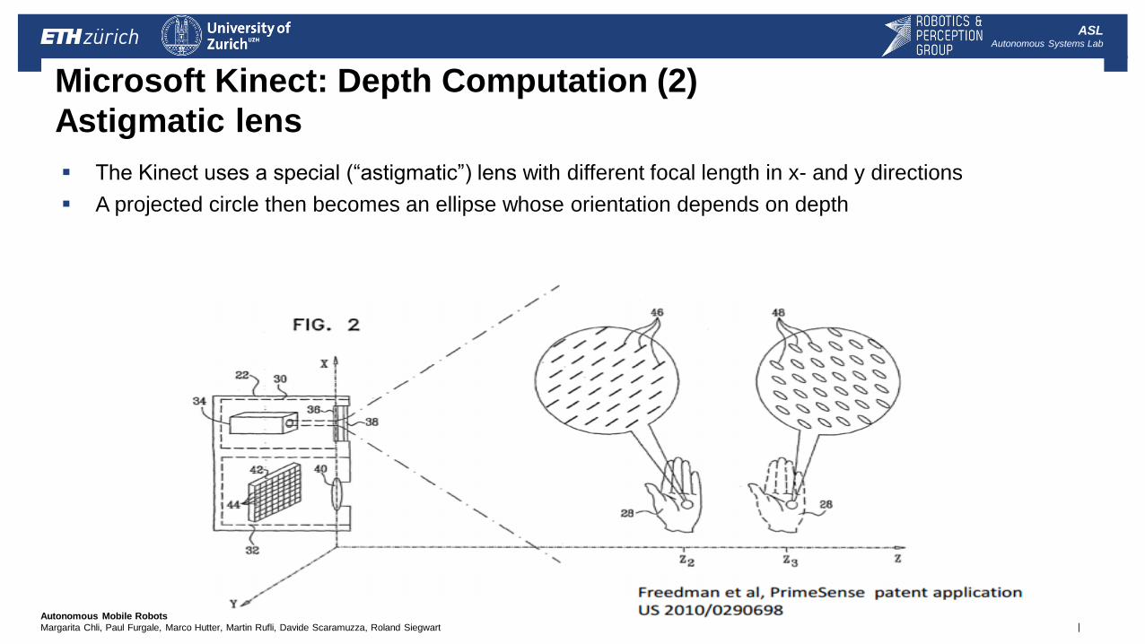
Microsoft Kinect: Depth Computation (2)
Astigmatic lens
The Kinect uses a special (“astigmatic”) lens with different focal length in x- and y directions
A projected circle then becomes an ellipse whose orientation depends on depth
| Autonomous Mobile Robots
Margarita Chli, Paul Furgale, Marco Hutter, Martin Rufli, Davide Scaramuzza, Roland Siegwart
ASL Autonomous Systems Lab
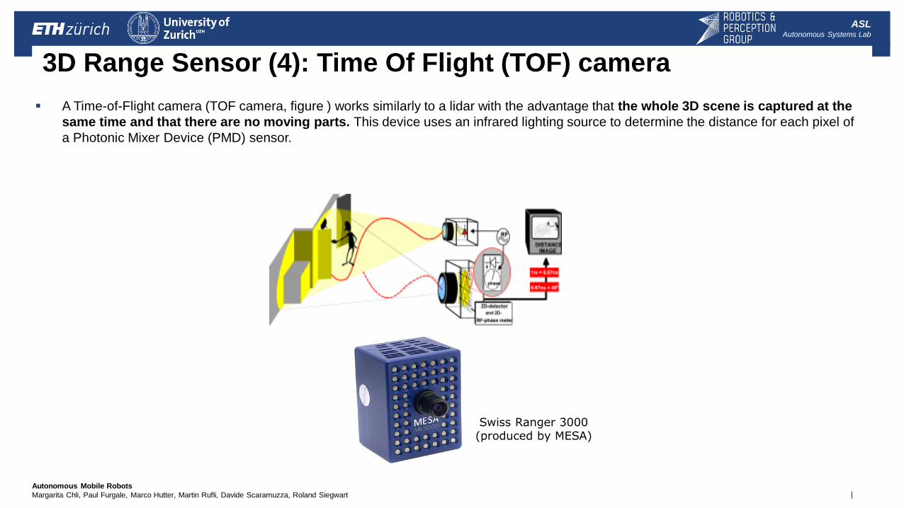
3D Range Sensor (4): Time Of Flight (TOF) camera
A Time-of-Flight camera (TOF camera, figure ) works similarly to a lidar with the advantage that the whole 3D scene is captured at the
same time and that there are no moving parts. This device uses an infrared lighting source to determine the distance for each pixel of
a Photonic Mixer Device (PMD) sensor.
Swiss Ranger 3000 (produced by MESA)
| Autonomous Mobile Robots
Margarita Chli, Paul Furgale, Marco Hutter, Martin Rufli, Davide Scaramuzza, Roland Siegwart
ASL Autonomous Systems Lab
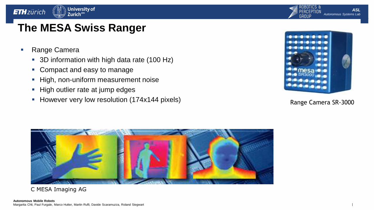
The MESA Swiss Ranger
Range Camera
3D information with high data rate (100 Hz)
Compact and easy to manage
High, non-uniform measurement noise
High outlier rate at jump edges
However very low resolution (174x144 pixels) Range Camera SR-3000
C MESA Imaging AG
| Autonomous Mobile Robots
Margarita Chli, Paul Furgale, Marco Hutter, Martin Rufli, Davide Scaramuzza, Roland Siegwart
ASL Autonomous Systems Lab
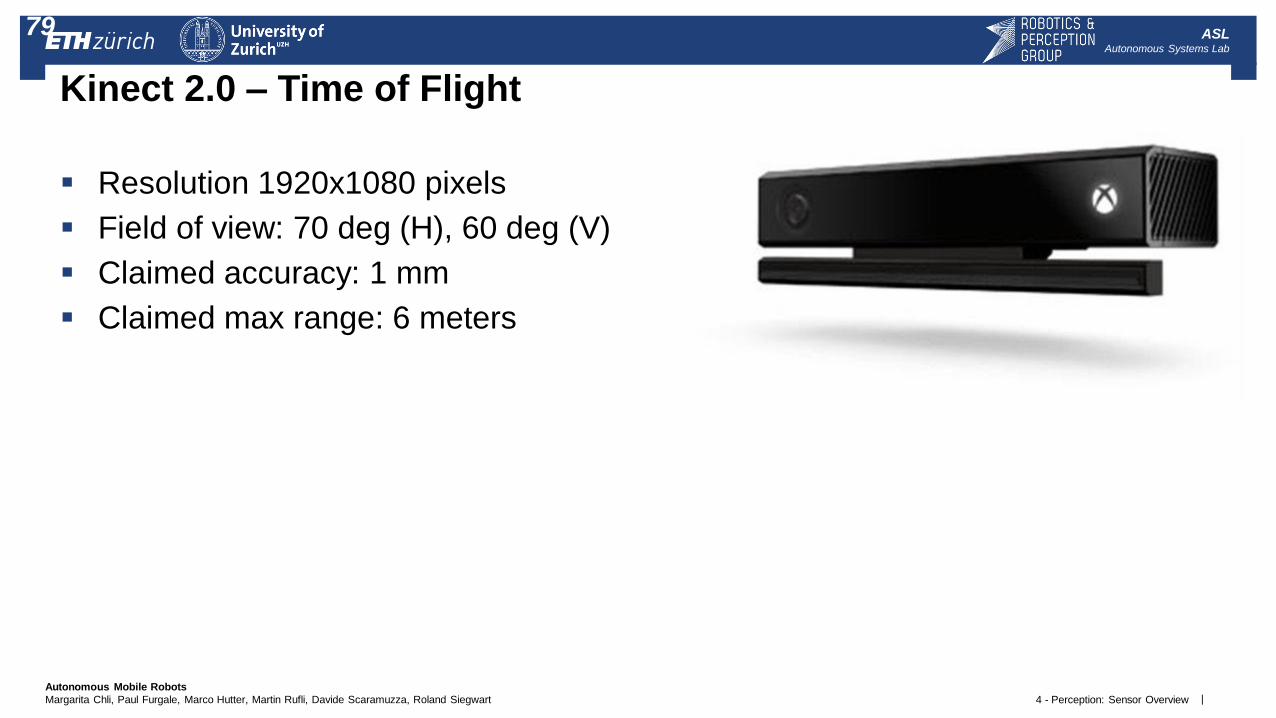
Kinect 2.0 – Time of Flight
Resolution 1920x1080 pixels
Field of view: 70 deg (H), 60 deg (V)
Claimed accuracy: 1 mm
Claimed max range: 6 meters
4 - Perception: Sensor Overview
79