Embed Size (px)
Citation preview
1
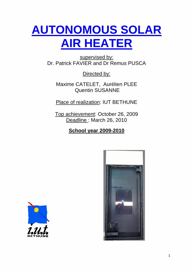
AUTONOMOUS SOLAR AIR HEATER
supervised by: Dr. Patrick FAVIER and Dr Remus PUSCA
Directed by:
Maxime CATELET, Aurélien PLEE Quentin SUSANNE
Place of realization: IUT BETHUNE
Top achievement: October 26, 2009
Deadline : March 26, 2010
School year 2009-2010
2
CONTENTS
Title
Page(s)
1. Acknowledgments 2 2. Definition of the project 3-4 3. Principle and system presentation 5 4. Regulatory system
1. Printed circuit 1. Microcontroller PIC 16F877 6 2. Charge Regulator 6 3. Fan Control 6-7 4. Motor Control 7 5. Board and final realization of the card 7-10 6. Statement of the fan speed and voltage at its terminals
depending on the duty cycle of PWM signal 11
2. Programming the PIC 16F877 12-15 5. Realization of the case
1. Sketches & Formatting 16 2. Drawings on Autocad 2000 and 2010 16-19 3. Cutting plastic parts 20 4. Assembling the box, tapping and screwing 20-21 5. Insulation 21 6. Capture more heat with the bottom aluminum 22 7. Installation and wiring the solar panel, fan and battery 23 8. Black painting of main case 24 9. The temperature sensor 25 10. The mechanical door and DC motor 26 11. Cover for the electronics and finite 27
6. Development 28 7. Conclusion 29
3
1. ACKNOWLEDGMENTS
First, we would like to thank the entire staff of the IUT BETHUNE who was always there to help us.
We would especially thank:
Mr. FAVIER, who has created this project and thanks to which it reached
Mr. PUSCA, for his help in programming
Mr. LEROY, for his help in cutting materials
4
DEFINITION OF THE PROJECT
This project, initiated by Mr. FAVIER, involves the design and realization of a greenhouse to warm the air in a chamber exposed to the sun to generate hot air for a home.
It has never been approached before, and is part of an international organization, which can be seen on the project site www.univ-artois.fr/icee.
The target users are those who want to find a heating alternative system to current solutions, autonomous and ecological.
This project is of interest to the Department GEII, in the sense that it could be a topic of tutorial and / or project tutored subject; it could also be used as a heating in a classroom.
It seduced us for various reasons:
Maxime CATELET: “I chose the project because, first, I am very interested in renewable energy. Besides, I chose a first-year project to protect a wind turbine. Secondly, this project makes it possible to practice many skills acquired during my education; it also allows studying certain areas that are not addressed during the DUT. "
Aurélien PLEE: “I liked this project immediately because, under the current conjecture, it seemed important to choose a subject with a strong environmental component. In addition, it approaches many subjects taught at the IUT and can therefore put them into practice and implement them together. "
Quentin SUSANNE: "The solar heating includes several fields (thermal, electronic, computer). This type of project is beneficial for anybody because it can be a single study or a residential installation. Furthermore, working trinomial requires rules of life and compliance... Finally it will be quick to make, test, adjust, optimize, and we already have ideas for expansion or additions of equipment to ensure continuity to the project for students come if we do not have time to add these options to base project. "
To achieve the most effective work possible, we have from the beginning, made a specification.
5
We divided the work according to the various issues the project addresses and our respective options to arrive at the following breakdown:
Maxime CATELET and Aurélien PLEE (Automatic option): work focused on the regulatory system
Quentin SUSANNE (Electricity option): work focuses on the mechanics and PV
The tentative plan is to work two weeks out of three, due to a session of three hours per week.
We have also identified various tools and materials we needed, namely:
- Hand tools, power tools, computer (MPLAB IDE, Tina, Eagle), Internet
- Double-glazing
- 2 Plates fiberglass 3 and 5 mm
- 1 PVC plate 15 mm
- Extruded polystyrene plate
- Black paint
- 3 Fans
- Sensor (s) Thermal (s)
- Micro-controller
- DC motor (s)
- PVC-tube
- Photovoltaic panel
- Battery
- Electronic components
- Hardware
- Epoxy
Finally, and to facilitate the preparation of this report, we noted the content of each session in a diary.
6
3. PRINCIPLE AND SYSTEM PRESENTATION
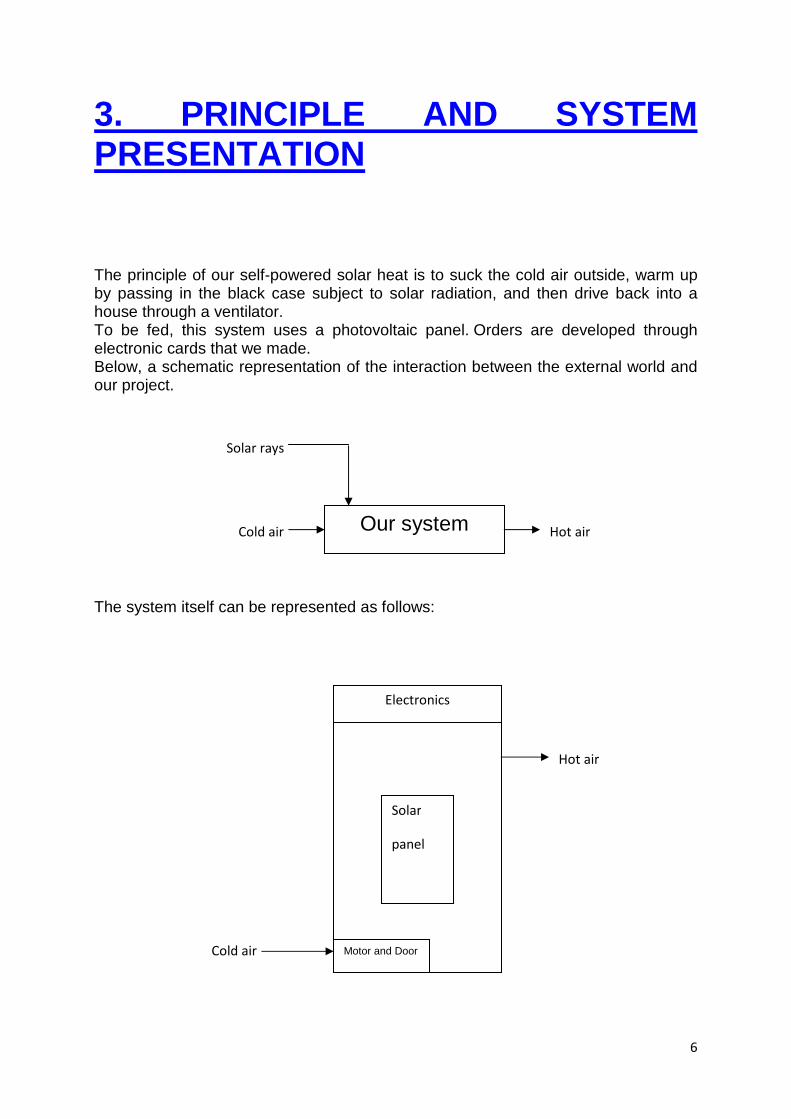
The principle of our self-powered solar heat is to suck the cold air outside, warm up by passing in the black case subject to solar radiation, and then drive back into a house through a ventilator. To be fed, this system uses a photovoltaic panel. Orders are developed through electronic cards that we made. Below, a schematic representation of the interaction between the external world and our project.
The system itself can be represented as follows:
Hot air Cold air
Solar rays
Our system
Hot air
Cold air
Electronics
Solar
panel
Motor and Door
7
4. REGULATORY SYSTEM
Our system is designed to be autonomous. To be more sustainable, it is powered by a solar panel of 7 Watts, provided by FREE ENERGY. The feed from the solar panel is based on the weather; it should charge a battery through a regulator. In addition, you have to drive the different organs, namely the fan and motor, depending on the temperature inside the housing.
This has led us to develop a printed circuit which is composed of charge controller, microcontroller and other components to drive the various parts of the system.
4.1 Printed Circuit
4.1.1 Microcontroller PIC 16F877
This component is necessary for us to manage the opening and closing the door through a motor and variable speed of both fans and acquisition of temperature end of the housing.
4.1.2 Charge Regulator
The feed from the solar panel must be controlled through an electronic component.
On the advice of Mr. FAVIER, we have chosen the home PB137 ST Electronics for its robustness and simplicity of implementation. Its main function is to control the charge of a 12 V lead acid battery. This one requires adding two capacitors of 1µF and 10µF and a heat sink.
4.1.3 Fan control
The fan must be powered by a voltage between 0 and 12V DC, the only possibility for varying the fan speed is to chop the continuous signal, so we used the PWM signal (modulation pulse width) provided by the microcontroller.
However, the pin providing the PIC PWM signal can’t be connected directly to the fan, for obvious reasons of course: indeed, a microcontroller delivers a maximum current of 200mA, while our fan consumes nearly 1A.
We then went through a transistor circuit.
8
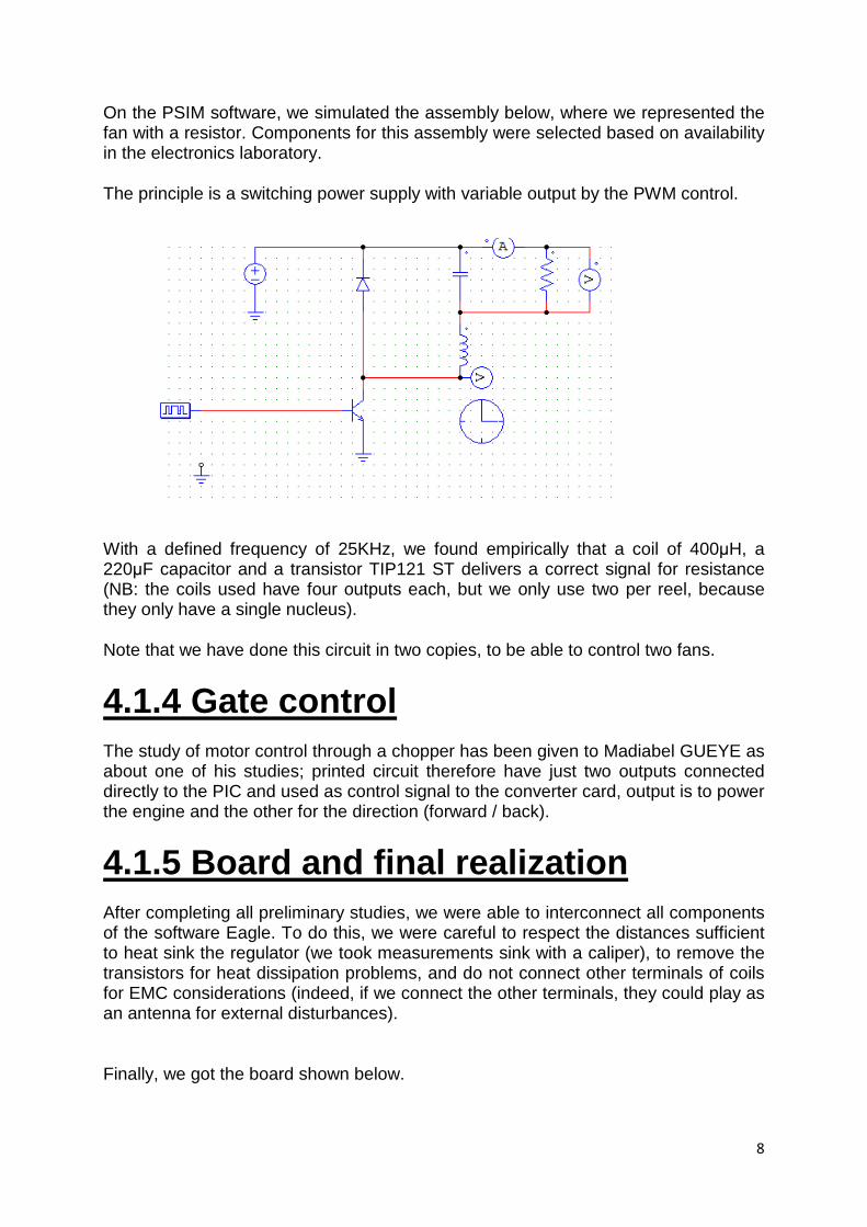
On the PSIM software, we simulated the assembly below, where we represented the fan with a resistor. Components for this assembly were selected based on availability in the electronics laboratory.
The principle is a switching power supply with variable output by the PWM control.
With a defined frequency of 25KHz, we found empirically that a coil of 400µH, a 220µF capacitor and a transistor TIP121 ST delivers a correct signal for resistance (NB: the coils used have four outputs each, but we only use two per reel, because they only have a single nucleus).
Note that we have done this circuit in two copies, to be able to control two fans.
4.1.4 Gate control
The study of motor control through a chopper has been given to Madiabel GUEYE as about one of his studies; printed circuit therefore have just two outputs connected directly to the PIC and used as control signal to the converter card, output is to power the engine and the other for the direction (forward / back).
4.1.5 Board and final realization
After completing all preliminary studies, we were able to interconnect all components of the software Eagle. To do this, we were careful to respect the distances sufficient to heat sink the regulator (we took measurements sink with a caliper), to remove the transistors for heat dissipation problems, and do not connect other terminals of coils for EMC considerations (indeed, if we connect the other terminals, they could play as an antenna for external disturbances).
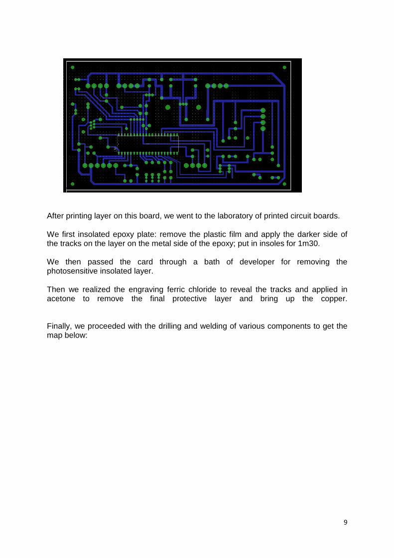
Finally, we got the board shown below.
9
After printing layer on this board, we went to the laboratory of printed circuit boards.
We first insolated epoxy plate: remove the plastic film and apply the darker side of the tracks on the layer on the metal side of the epoxy; put in insoles for 1m30.
We then passed the card through a bath of developer for removing the photosensitive insolated layer.
Then we realized the engraving ferric chloride to reveal the tracks and applied in acetone to remove the final protective layer and bring up the copper. Finally, we proceeded with the drilling and welding of various components to get the map below:
10
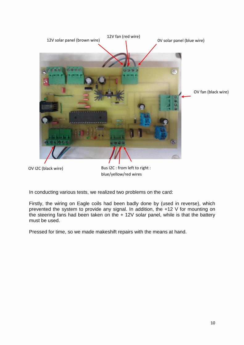
In conducting various tests, we realized two problems on the card:
Firstly, the wiring on Eagle coils had been badly done by (used in reverse), which prevented the system to provide any signal. In addition, the +12 V for mounting on the steering fans had been taken on the + 12V solar panel, while is that the battery must be used. Pressed for time, so we made makeshift repairs with the means at hand.
OV fan (black wire)
Bus I2C : from left to right :
blue/yellow/red wires
OV I2C (black wire)
12V solar panel (brown wire) 0V solar panel (blue wire) 12V fan (red wire)
11
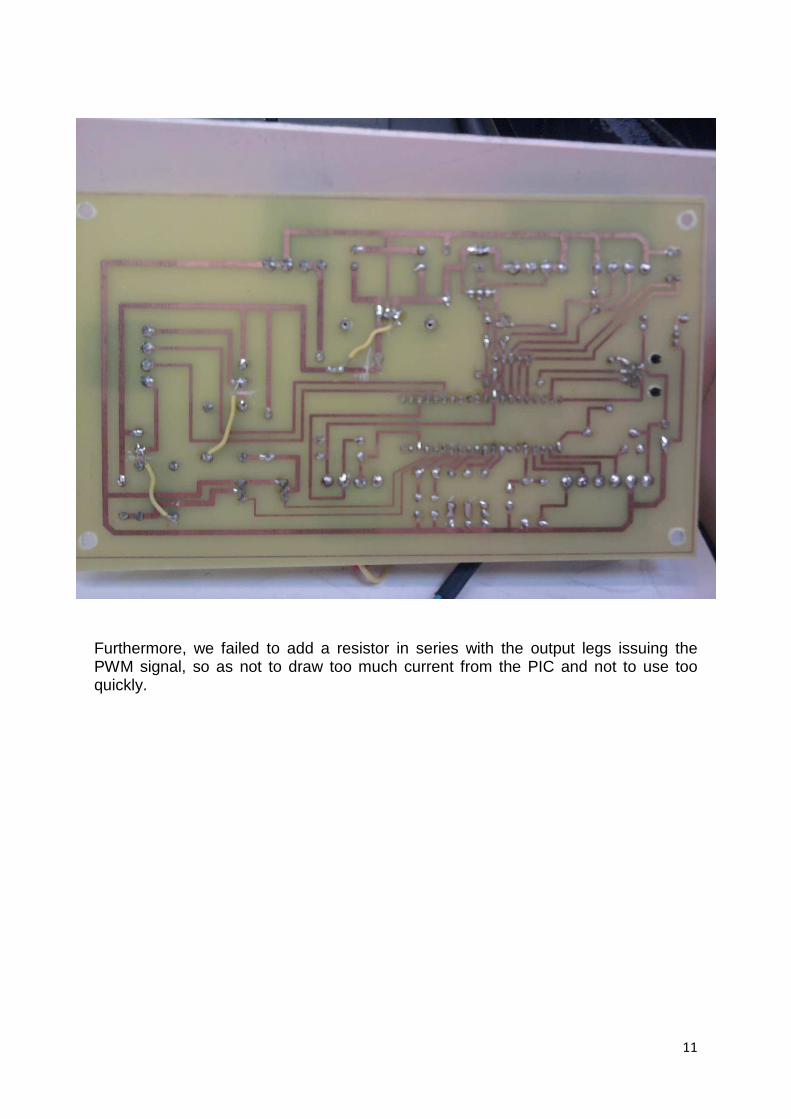
Furthermore, we failed to add a resistor in series with the output legs issuing the PWM signal, so as not to draw too much current from the PIC and not to use too quickly.
12
4.1.6 Statement of the fan speed and voltage at its terminals depending on the duty cycle of PWM signal
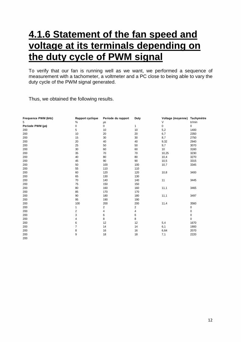
To verify that our fan is running well as we want, we performed a sequence of measurement with a tachometer, a voltmeter and a PC close to being able to vary the duty cycle of the PWM signal generated.
Thus, we obtained the following results.
Frequence PWM (kHz) Rapport cyclique Periode du rappo rt Duty Voltage (moyenne) Tachymètre5 % µs V tr/minPeriode PWM (µs) 0 0 1 0 0200 5 10 10 5,2 1400200 10 20 20 6,7 2350200 15 30 30 8,7 2750200 20 40 40 9,32 2940200 25 50 50 9,7 3070200 30 60 60 10 3160200 35 70 70 10,25 3230200 40 80 80 10,4 3270200 45 90 90 10,5 3315200 50 100 100 10,7 3345200 55 110 110200 60 120 120 10,8 3400200 65 130 130200 70 140 140 11 3445200 75 150 150200 80 160 160 11,1 3465200 85 170 170200 90 180 180 11,1 3497200 95 190 190200 100 200 200 11,4 3560200 1 2 2 0200 2 4 4 0200 3 6 6 0200 4 8 8 0200 6 12 12 5,4 1670200 7 14 14 6,1 1900200 8 16 16 6,64 2070200 9 18 18 7,1 2220200
13
4.2. Programming the PIC 16F877
Once the card is properly made and repaired, we were able to pass the planning stage itself.
After talking with Mr. FAVIER, we decided to organize the program in the most readable as possible, that is to say commenting on program lines and using as much as possible to subroutines.
How the program is as follows:
• If the switch is in position 0-1, the program executes the loop named testDiagnostic: to verify the proper functioning of the system. We chose to flash the yellow LED three times to run the fan for two seconds.
• If the switch is in another position, the program executes the loop gestionVentilateurMoteur. Within this loop, we shall first call to the subfunction acquisitionTempBoitier which, as its name suggests, is to acquire the temperature after the sensor in the housing. If the temperature exceeds 45 °C, and so it is above 35 °C, the fan will speed up roa d to extract heat and send it in the house and the red LED flashes. If the temperature drops below 35 ° C, the fan does not turn and the green LED blinks.
Hereafter, is the program management of electronic solar thermal self.
/* Program Management Electronic autonomous solar thermal
IUT BETHUNE - 2009/2010
*/ #include "ccs_project.h" #include <stdio.h> #ZERO_RAM #define sw2 PIN_B2 #define sw1 PIN_B3 #define ventilo_entree PIN_C1 #define ventilo_sortie PIN_C2 #define sens_moteur PIN_C6 #define marche_moteur PIN_C7 #define del_verte PIN_E0 #define del_jaune PIN_E1 #define del_rouge PIN_E2
14
signed int data; signed int valeur; int1 ack; int temp; void testDiagnostic(){ int duty=18; set_pwm1_duty(duty); // the high time will be: // if value is INT: // value*4*(1/clock)*t2div // for example a value of 50, and t2div=1, and clock=4MHz, // high time is 50us. For 5kHz PWM, it means 25% duty // WARNING: A value to high or low will // prevent the output from changing. // t2div=prescaler=1 ou 4 ou 16 delay_ms(2000); set_pwm1_duty(0); output_high(del_jaune); delay_ms(250); output_low(del_jaune); delay_ms(250); output_high(del_jaune); delay_ms(250); output_low(del_jaune); delay_ms(250); output_high(del_jaune); delay_ms(250); output_low(del_jaune); delay_ms(250); delay_ms(1000); } void acquisitionTempBoitier(){ i2c_start(); ack=i2c_write(0x9A); delay_ms(1); ack=i2c_write(0x00); delay_ms(1); i2c_start(); ack=i2c_write(0x9B); delay_ms(1); data=i2c_read(1); i2c_stop(); temp=data;
15
} void gestionVentilateurMoteur(){ acquisitionTempBoitier(); if(temp>=45) { if(temp>=35) { set_pwm1_duty(108); acquisitionTempBoitier() ; output_high(del_rouge); delay_ms(250); output_low(del_rouge); delay_ms(250); } } if(temp<35) { set_pwm1_duty(0); output_high(del_verte); delay_ms(250); output_low(del_verte); delay_ms(250); } } void main() { setup_ccp1(CCP_PWM);// Configure CCP1 as a PWM setup_ccp2(CCP_PWM);// Configure CCP2 as a PWM setup_adc_ports(NO_ANALOGS); setup_adc(ADC_OFF); setup_psp(PSP_DISABLED); setup_timer_0(RTCC_INTERNAL|RTCC_DIV_256); setup_timer_1(T1_DISABLED); setup_timer_2(T2_DIV_BY_1,199,1); // t2_div_by=Prescaler=1,PR2=199 // The cycle time will be (1/clock)*4*t2div*(period+1) // In this program clock=10000000 and period=127 (below) // For the three possible selections the cycle time is: // (1/10000000)*4*1*128 = 51.2 us or 19.5 khz // (1/10000000)*4*4*128 = 204.8 us or 4.9 khz // (1/10000000)*4*16*128= 819.2 us or 1.2 khz // valeur fixee a ne plus modif : 5 kHz i2c_start(); ack=i2c_write(0x9A); delay_ms(1);
16
ack=i2c_write(0x01); delay_ms(1); ack=i2c_write(0x00); delay_ms(1); i2c_stop(); while(1) { if( (input(sw1)==1) & (input(sw2)==0) ) { testDiagnostic(); } else { gestionVentilateurMoteur(); } } }
17
5. REALIZATION OF THE CASE
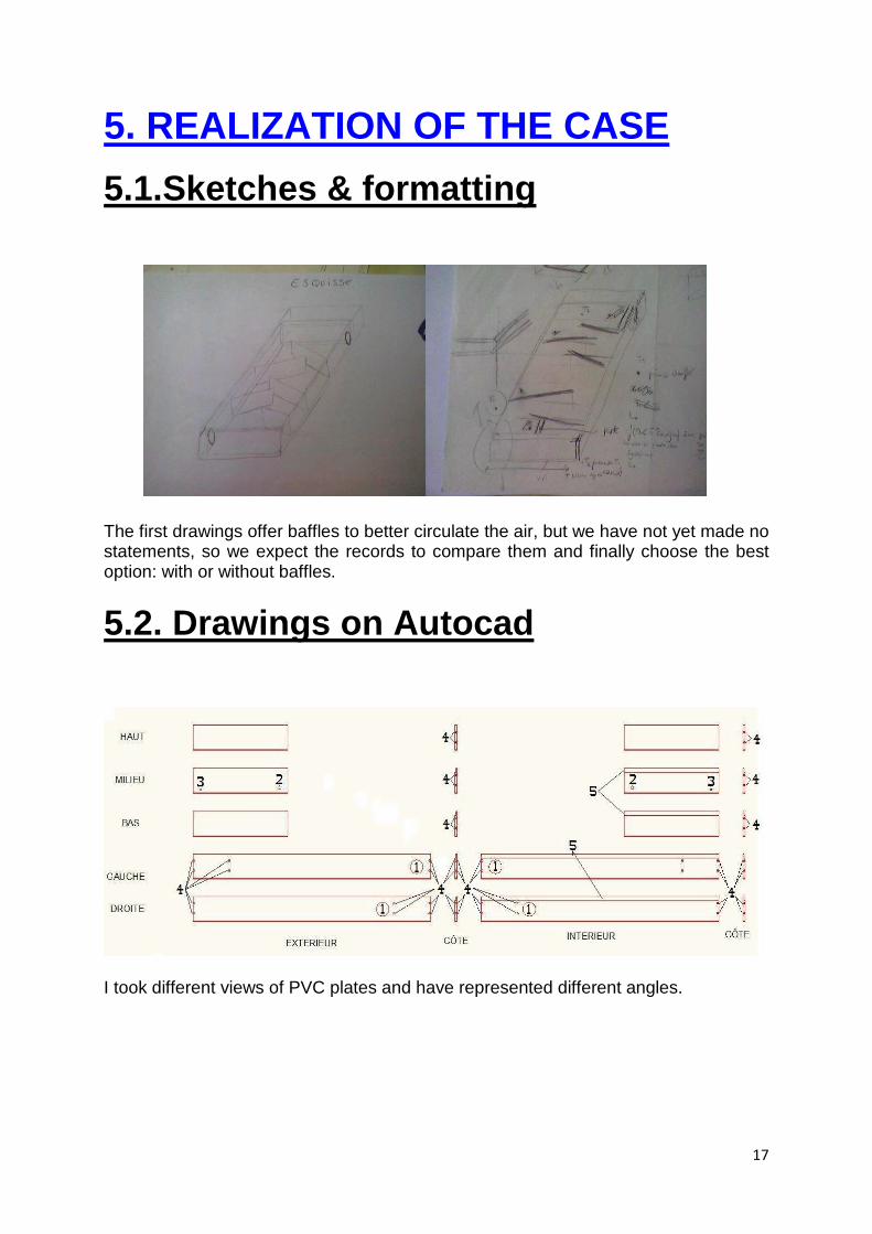
5.1.Sketches & formatting
The first drawings offer baffles to better circulate the air, but we have not yet made no statements, so we expect the records to compare them and finally choose the best option: with or without baffles.
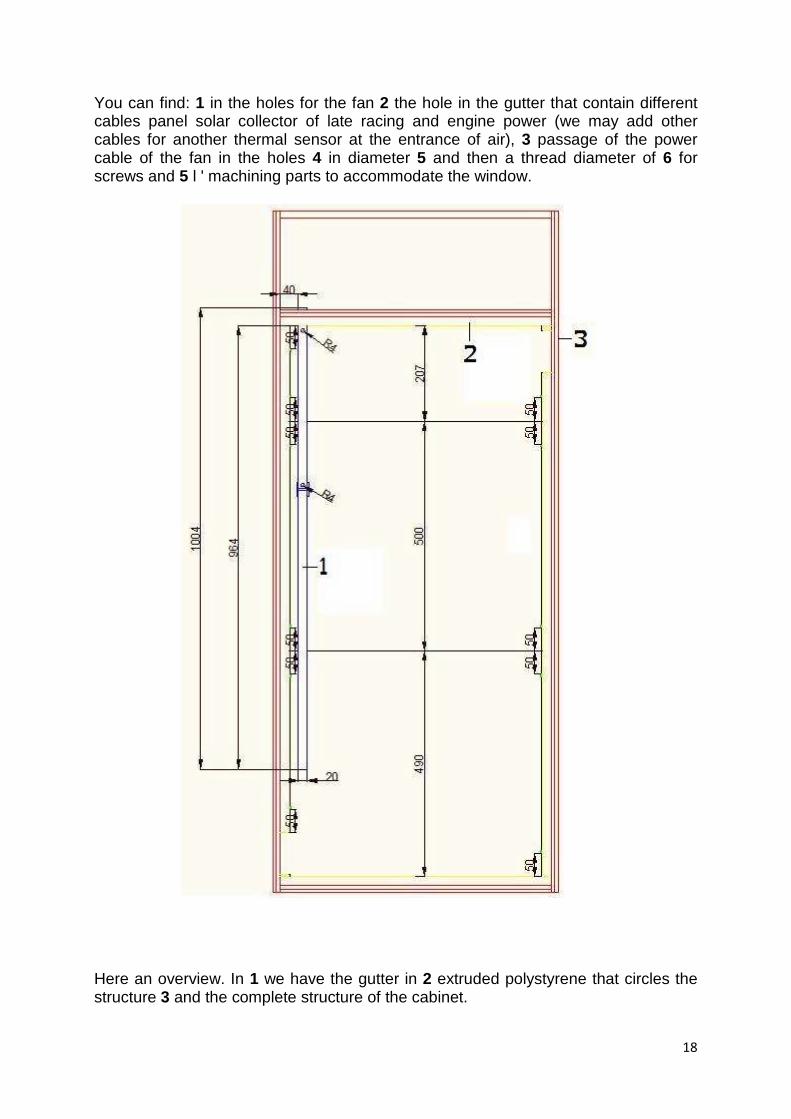
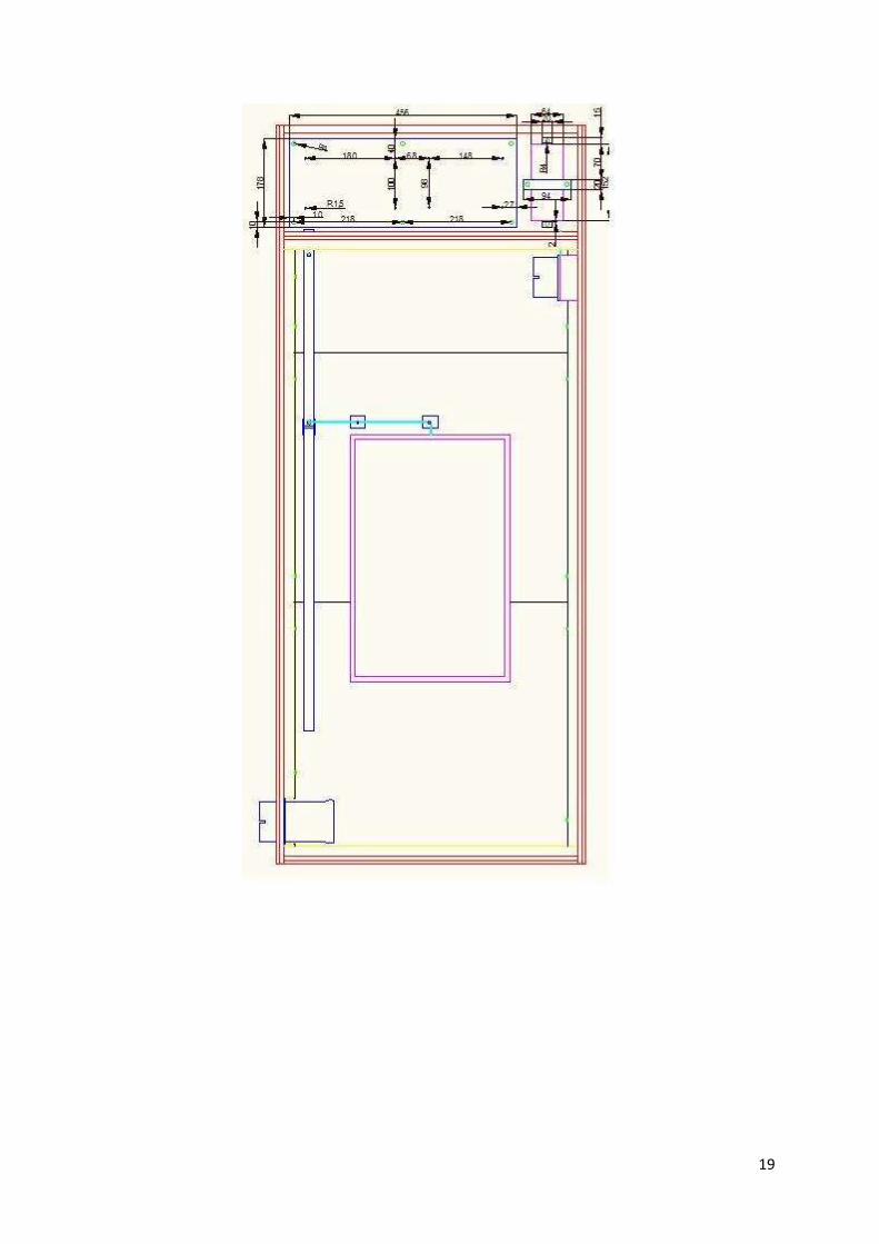
5.2. Drawings on Autocad
I took different views of PVC plates and have represented different angles.
18
You can find: 1 in the holes for the fan 2 the hole in the gutter that contain different cables panel solar collector of late racing and engine power (we may add other cables for another thermal sensor at the entrance of air), 3 passage of the power cable of the fan in the holes 4 in diameter 5 and then a thread diameter of 6 for screws and 5 l ' machining parts to accommodate the window.
Here an overview. In 1 we have the gutter in 2 extruded polystyrene that circles the structure 3 and the complete structure of the cabinet.
19
20
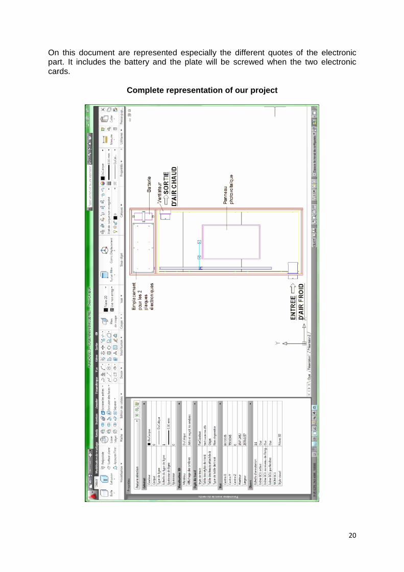
On this document are represented especially the different quotes of the electronic part. It includes the battery and the plate will be screwed when the two electronic cards.
Complete representation of our project
21
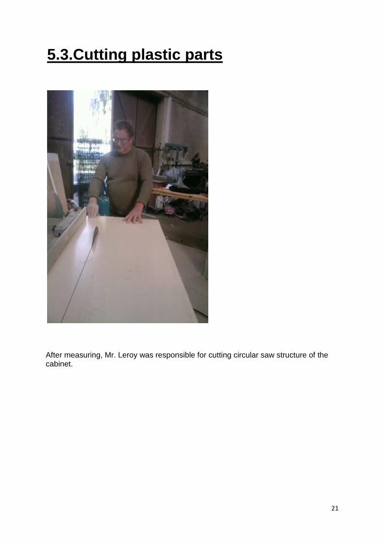
5.3.Cutting plastic parts
After measuring, Mr. Leroy was responsible for cutting circular saw structure of the cabinet.
22
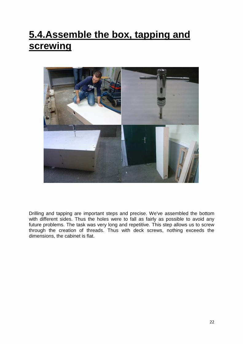
5.4.Assemble the box, tapping and screwing
Drilling and tapping are important steps and precise. We've assembled the bottom with different sides. Thus the holes were to fall as fairly as possible to avoid any future problems. The task was very long and repetitive. This step allows us to screw through the creation of threads. Thus with deck screws, nothing exceeds the dimensions, the cabinet is flat.
23
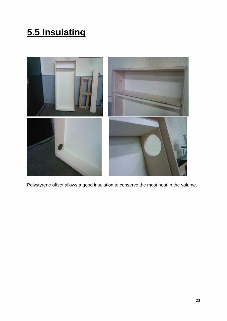
5.5 Insulating
Polystyrene offset allows a good insulation to conserve the most heat in the volume.
24
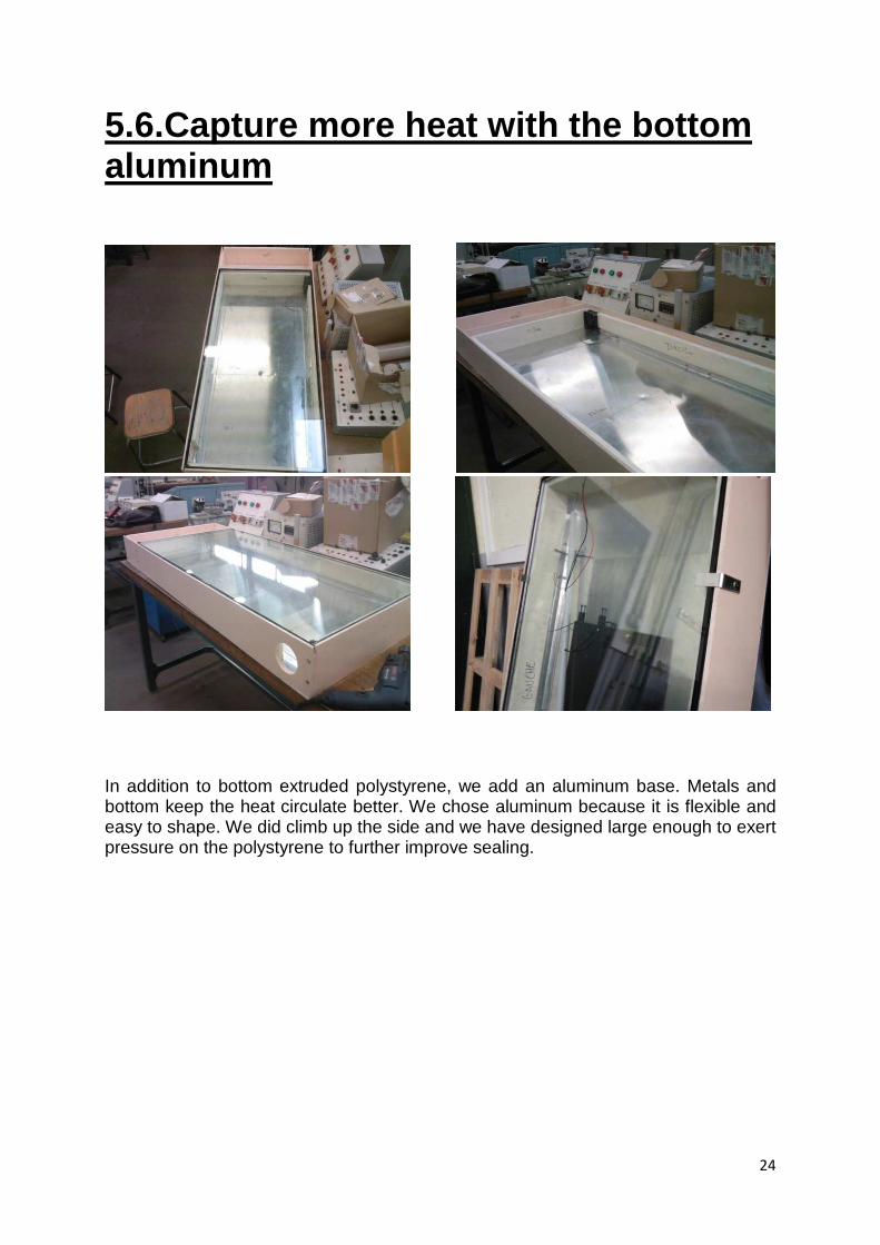
5.6.Capture more heat with the bottom aluminum
In addition to bottom extruded polystyrene, we add an aluminum base. Metals and bottom keep the heat circulate better. We chose aluminum because it is flexible and easy to shape. We did climb up the side and we have designed large enough to exert pressure on the polystyrene to further improve sealing.
25
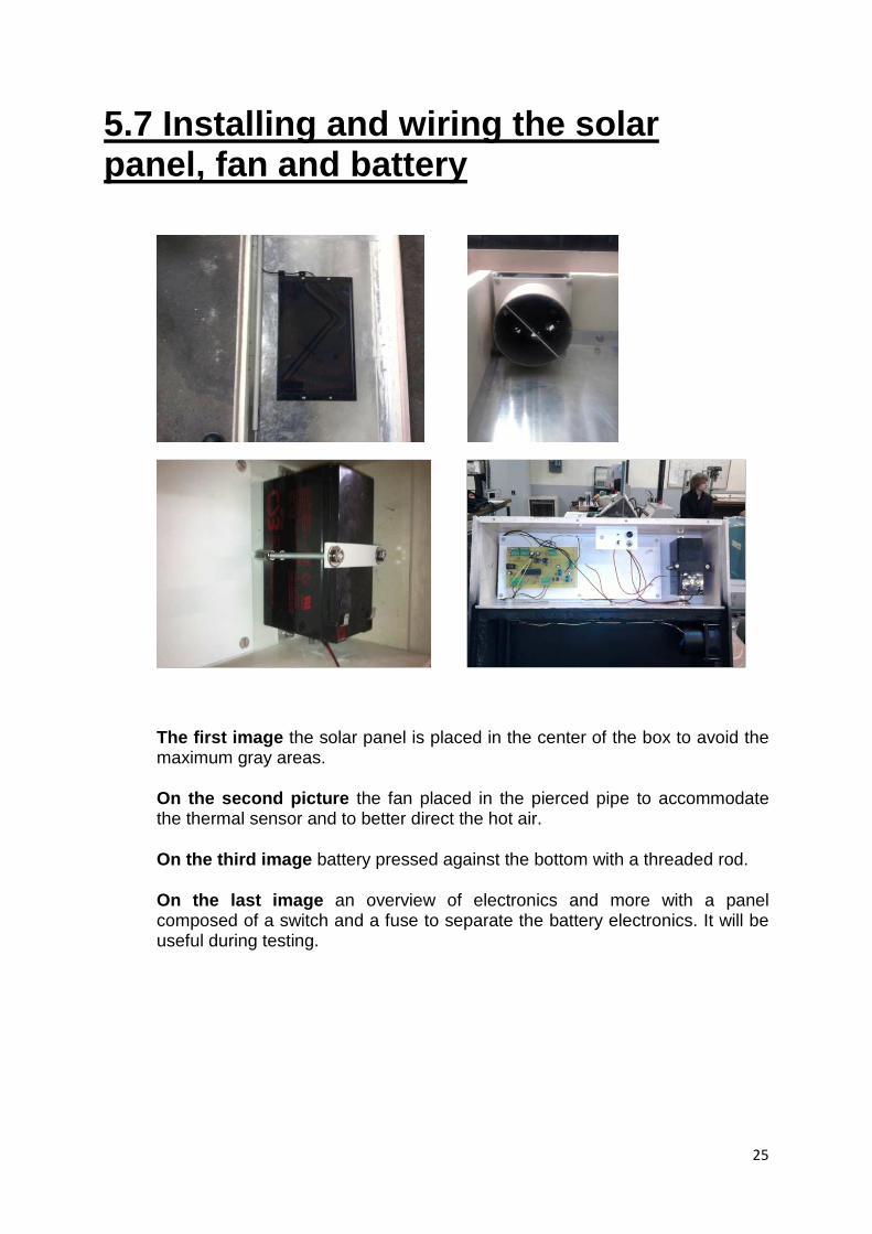
5.7 Installing and wiring the solar panel, fan and battery
The first image the solar panel is placed in the center of the box to avoid the maximum gray areas.
On the second picture the fan placed in the pierced pipe to accommodate the thermal sensor and to better direct the hot air.
On the third image battery pressed against the bottom with a threaded rod.
On the last image an overview of electronics and more with a panel composed of a switch and a fuse to separate the battery electronics. It will be useful during testing.
26
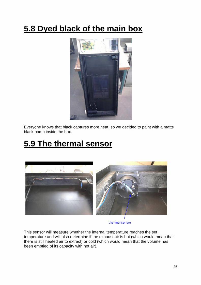
5.8 Dyed black of the main box
Everyone knows that black captures more heat, so we decided to paint with a matte black bomb inside the box.
5.9 The thermal sensor
This sensor will measure whether the internal temperature reaches the set temperature and will also determine if the exhaust air is hot (which would mean that there is still heated air to extract) or cold (which would mean that the volume has been emptied of its capacity with hot air).
thermal sensor
27
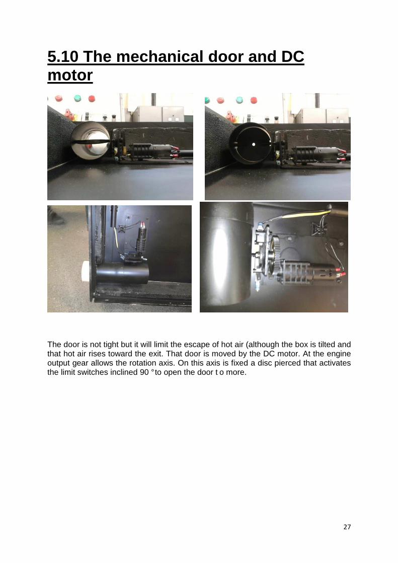
5.10 The mechanical door and DC motor
The door is not tight but it will limit the escape of hot air (although the box is tilted and that hot air rises toward the exit. That door is moved by the DC motor. At the engine output gear allows the rotation axis. On this axis is fixed a disc pierced that activates the limit switches inclined 90 ° to open the door t o more.
28
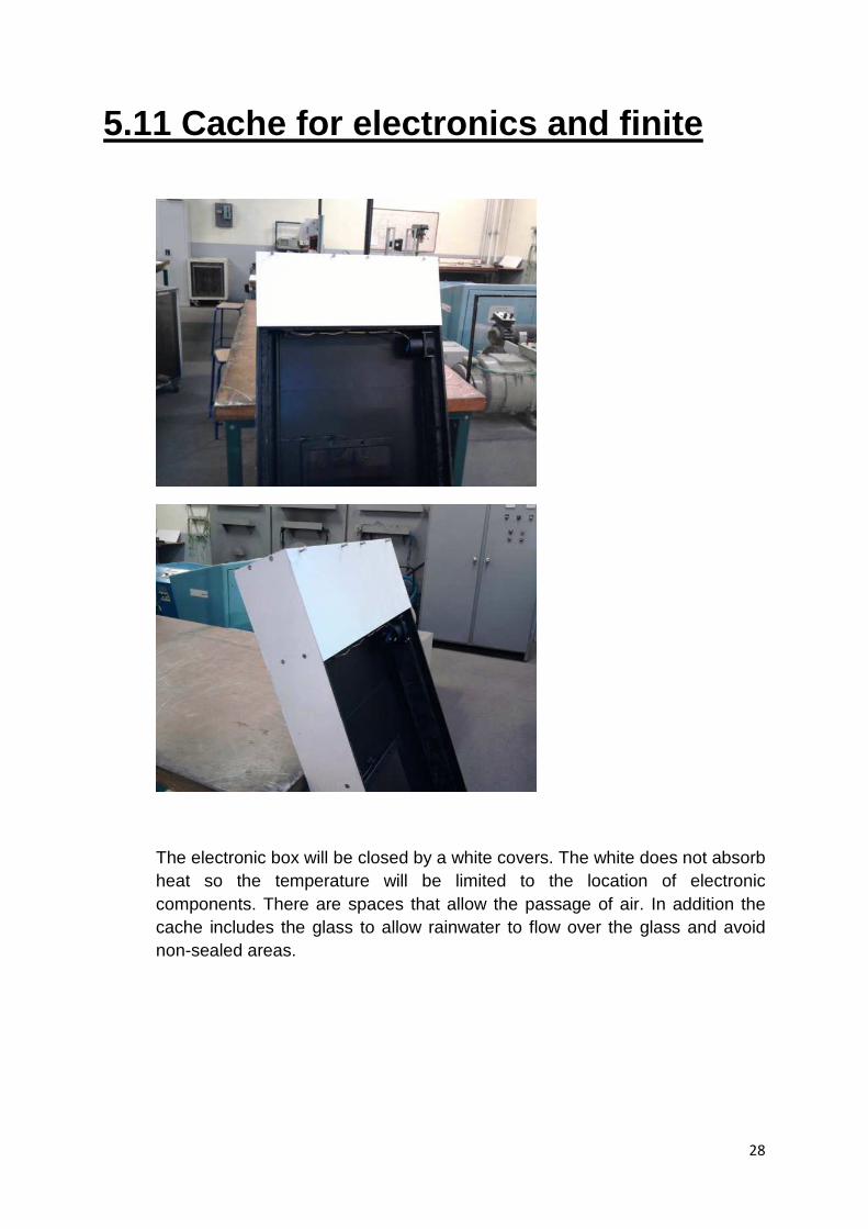
5.11 Cache for electronics and finite
The electronic box will be closed by a white covers. The white does not absorb heat so the temperature will be limited to the location of electronic components. There are spaces that allow the passage of air. In addition the cache includes the glass to allow rainwater to flow over the glass and avoid non-sealed areas.
29
6. DEVELOPMENT
To further study of this project tutored subject, we have allowed ourselves to propose a few elements for thought.
Thus, a new electronic card may first be conducted properly, on board the Eagle is already updated.
Similarly, resistance could be added at the PWM output of the microcontroller in order to limit the base currents of transistors.
Regarding the computer program, adding additional temperature sensors involve the creation of an additional subroutine. Indeed, the temperature reading is only possible with just a single component on the I2C bus. It would create a new protocol for communication between microcontroller and components on the I2C bus. Similarly, other functions could be created, including adding a fan to stir the air into the enclosure.
Regarding the mechanical part, several ideas have been issued.
Firstly, the aluminum plates exert pressure on the walls right and left, which deforms them. So there is a day that was created between the window and structure. We can put a metal bar inside the cabinet to bring the two sides in the tie to the inside. To better distribute the tension bar on the walls should be placed at the center, but at the center will generate a gray area on the solar panel.
During bending, the solvent included in the painting has decomposed polystyrene. Buy a painting adapted and re-insulate although we realized the problem early enough to avoid too much damage.
We cut in squares of aluminum bent under the weight of the window when it tilts too the entire module. Cut new squares in a stronger metal.
Other ideas are also coming, such as a digital display in front of the case which seems feasible given that we approach this subject in first year computer science. In addition, humidity sensors could be placed to prevent excessive moisture in the cabinet and signal excess, and the internal walls to circulate hot air in a corridor as proposed in the drawings before the project.
We are confident that people will resume this project, will have other ideas too interesting issue.
30
7. CONCLUSION
We met the specifications and deadlines, provided solutions to problems, improved conditions of access to different parts of the module.
The agreement in the group remained good throughout the project, which is an important element for all of us.
This project was quite a place within the Department GEII, in fact, it could be a topic of TP or tutoring project for future students. One could also consider putting into service, linking it to a room to heat it.
Finally, no member of our team have no regrets for choosing this project, in which we all learned about others and ourselves.
Aurélien PLEE: "I do not regret that choice, because this project allowed me to implement my knowledge in computer, confront me with technical problems, to find solutions, and a deadline, the doors open from March 6, 2010, for which I have attempted to provide a concrete work for presentation to the visitors. In addition, teamwork has taught me much about understanding how the various characters. "
Quentin SUSANNE: "Personally I learned a lot about the different working methods. I am a little more familiar with the mechanical aspect of the project but also the appearance and electrical installation. The design of a renewable energy project is always fun especially today. I am very happy to leave a clean work surface and composed of several features that will please everyone, everyone is benefiting. That's what I was most happy and I realized that solar heating system. "
Maxime CATELET: "This project pleased me and allowed me to practice many things being learned and to have new knowledge in areas different from those studied in OTC GEII. The tutored projects can be confronted with problems or requirements, which is not the case during class. I am glad that ultimately provides a clean work that works, and allow students the next few years to improve this project."
This was so for all of us a very good experience and it is with some pride that we were able to bring it to the realization of a prototype.