Embed Size (px)
Citation preview

11th edition, EU region
Autonomous Search and Rescue Vehicles Design Report
Mihnea Vlad Pop [email protected]
Alex Tatar [email protected]
Advisor: Lecturer Dr.-Ing. Germán-Salló Zoltán
Petru Maior University of Târgu Mureș Târgu Mureș, Romania
May 16, 2015

‘Autonomous Search and Rescue Vehicles’ Design Report
2
Table of content 1. Introduction…………………………………………………………………………………………………………………………….......2 2. Design……………………………………………………………………………………………………………………………................5
2.1. Hardware……………………………………………………………………………………………………………………….......5 2.1.1. First mobile platform................................................................................................5
2.1.1.1. Nexys4DDR FPGA board............................................................................8 2.1.1.2. Mobile platforms.......................................................................................9 2.1.1.3. LCD Screen.................................................................................................9 2.1.1.4. Infrared thermometer.............................................................................10 2.1.1.5. Ultrasonic sensor.....................................................................................11 2.1.1.6. Magnetometer........................................................................................11 2.1.1.7. RF transmitter.........................................................................................12 2.1.1.8. Dual DC motor driver..............................................................................13 2.1.1.9. Logic level converter...............................................................................14 2.1.1.10. Rotary Encoders....................................................................................14 2.1.1.11. Miscellaneous modules........................................................................14
2.1.2. Second mobile platform.........................................................................................15 2.1.2.1. ESC..........................................................................................................16 2.1.2.2. RF Receiver.............................................................................................16 2.1.2.3. Servomotors...........................................................................................17 2.1.2.4. Miscellaneous modules..........................................................................17
2.2. Software.................................................................................................................................18 2.2.1. I2C bus master controller (i2c_master.vhd)...........................................................19 2.2.2. Nexys4DDR on-board peripherals..........................................................................19
2.2.2.1. Buttons and switches (debouncer.vhd)..................................................19 2.2.2.2. Seven-segment LED displays (seven_seg_disp.vhd)...............................20 2.2.2.3. Ambient thermometer (ambient_thermo.vhd)......................................21
2.2.3. LCD screen (LCD.vhd)..............................................................................................22 2.2.4. Infrared thermometer (ir_thermo.vhd)..................................................................23 2.2.5. Ultrasound sensors (ultrasound.vhd).....................................................................24 2.2.6. Magnetometer (magnetometer.vhd).....................................................................25 2.2.7. RF Transmitter (rf_motor_driver.vhd)....................................................................26 2.2.8. Motors driver (motor_driver.vhd)..........................................................................28 2.2.9. Top-level module (top_module.vhd)......................................................................29
3. Discussion........................................................................................................................................31 3.1. Resource requirements..........................................................................................................31 3.2. Problems encountered...........................................................................................................31
4. References.......................................................................................................................................32 4.1. External documentation.........................................................................................................32 4.2. Source code............................................................................................................................33
4.2.1. ambient_thermo.vhd..............................................................................................34 4.2.2. debouncer.vhd........................................................................................................35 4.2.3. i2c_master.vhd........................................................................................................43 4.2.4. ir_thermo.vhd.........................................................................................................46 4.2.5. LCD.vhd...................................................................................................................48 4.2.6. magnetometer.vhd.................................................................................................50 4.2.7. motor_driver.vhd....................................................................................................57 4.2.8. rf_motor_driver.vhd...............................................................................................62 4.2.9. seven_seg_disp.vhd................................................................................................65 4.2.10. top_module.vhd....................................................................................................67 4.2.11. ultrasound.vhd......................................................................................................91 4.2.12. constraints.xdc......................................................................................................93

‘Autonomous Search and Rescue Vehicles’ Design Report
3
1. Introduction This design report presents an application for the 11-th edition of Digilent’s
Design Contest, application that consists of two mobile platforms. The controlling unit is powered by a Nexys4DDR development board based on the Xilinx Artix-7 XC7A100T Field Programmable Gate Array (FPGA).
The first (main) platform will autonomously traverse an obstacle-filled area (the “search” phase) to find the target (or “victim”, in this case a hands warmer). Once the target has been found the direct route from the starting point will be calculated and then traversed by the second platform, without any sensory aid. Once it too will reach the target, it will physically pick-up it up (the “rescue” phase), completing the operation. To detect obstacles ultrasound distance measuring devices are implemented, while for the target recognition a contactless infrared thermometer was necessary in order to measure instant surface temperature from a distance.
Throughout this project, certain development steps required protocol decoding (for the Infrared Thermometer and RF transmitter), information which could prove valuable for future use.
In short, one mobile platform searches for a certain target in a set area, all while avoiding obstacles. After finding it, the second platform will then follow a direct route to it, and pick the target up. This reproduces, in smaller terms, a two-part rescue mission.
We consider it as the main objective the opportunity to explore and learn new ways of designing and implementing certain tasks, tasks which may prove difficult on other hardware architectures (most notably microcontrollers, or other RISC machines, like ARM).
In order to accomplish its task (finding and ‘rescuing’ its target), the design will include the following features:
a. Hardware: - move a mobile platform through an area with obstacles, - to avoid hitting into obstacles, ultrasound distance measurement is used via
dedicated modules, for quick and accurate detection, - to detect the target, the surface temperature is measured multiple times per
second, waiting for a higher value with the signification that the target (hands warmer – which is tens of degrees Celsius above room temperature) is in front of the platform,
- to ease the target detection, the infrared reading is compared to the value outputted from an on-board (ADT7420) digital ambient thermometer,
- in order for the platform to accurately move forward, backwards and rotate left and right, certain methods of error-reduction were implemented, including

‘Autonomous Search and Rescue Vehicles’ Design Report
4
individual wheel rotation steps measurement using rotary encoders, and heading calculation using an 3-axis magnetometer (digital compass),
- to allow the user to observe the current state of operation, LEDs and an LCD screen provides visual information at a glance,
- user interface is possible using on-board buttons and switches, - communication between the two platforms is accomplished using a pair of
2.4GHz radio transmitter/receiver modules, assuring interference-free control.
b. Software: - In the pursuit to further improve the overall efficiency and required time to
finish the first phase of the operation (Search), all obstacles detected and movements performed by the platform are memorized, so that at each step the memory is checked before checking with the actual sensors – this allows quicker workflow, as the device will not check for obstacles in a position on the map where it has previously detected one, and also will not go twice on a trace it has already been on,
- finally, to pin-point precisely the target position and route to it, the memory keeps track of the current platform position and that of the target, information which is used in the second and third phase – ‘Reposition’ and ‘Rescue’,
- during the ‘reposition’ phase, the resulted area map is consulted, so that the first platform will not be in the way of the second one, which it turn needs to reach the target for completing the final part, the ‘Rescue’. This project incorporates the hardware, and also the software design. Hardware was done by us, using ready made parts or salvaged ones. The software design, written in VHSIC (Very High Speed Integrated Circuit) Hardware Description Language, or VHDL, did not rely on any IP (intellectual property), software libraries (besides the mandatory ones), nor second-/third-party sources (such as templates, demo codes, source generators).
Thus, to reproduce the design in software terms, only the following tools are required: - Xilinx Vivado v2014.4 development environment (newer or even older software versions may still be useable, including Xilinx’s ISE suite), on a compatible operating system (in our case, Microsoft Windows 8.1 64-bit edition), - Notepad++ - even though Vivado suite is extremely powerful, certain text-oriented operations are not (yet) implemented (such as search, replace, highlighting and auto-formatting). Other software solutions, such as simulators, were not proven necessary during the development phase. For the hardware build, no special tools were used, and none are necessary to operate the two platforms, besides the hand warmer(s), and objects that can be repurposed as physical obstacles.

‘Autonomous Search and Rescue Vehicles’ Design Report
5
At the time of writing, the software covers all the basic features listed above. Regarding the hardware, we don’t consider it complete, even though it allows the completion of its tasks, as it still presents certain problems. Further discussion at the “Problems Encountered” sub-chapter. The motivation behind this design, as mentioned before, is to allow us to gain experience in solving problems in an easier, more direct route, than by using the more accessible, general-use hardware platforms (Atmel’s AVR range and Microchip’s PIC8). Although those platforms provide more straight-forward access to different technologies (digital interfaces such as UART, I2C, and SPI, algorithms, operators and data representations – floating-point numbers, trigonometric functions - sin, cos, tan, arctan) through the use of libraries and from third-party developers, more knowledge may be obtained by accomplishing the required tasks writing code from scratch. Also, certain hardware limitations are negated, such as fixed microcontroller modules (CCP – capture, compare, PWM), but added as well (in standard terms, FPGA architecture works with integer or at most fixed-point values representation, and not include floating-point). For each hardware module used, documentation and in-line code commenting are provided in hope of describing the method of realizing the hardware-software interface and/or data processing algorithms used. Because the project implies the use of certain devices for which, currently no public-accessible documentation is available, manually ‘discovered’ interfacing methods are described (where applicable).

‘Autonomous Search and Rescue Vehicles’ Design Report
6
2. Design 2.1. Hardware 2.1.1. First mobile platform
Rotary Encoders
LCD Screen
Ultrasound
Distance
Measurers
IR Thermometer
Nexys4DDR
board
Magnetometer
Step-Up
SMPS
Step-Down
SMPS
Motors Driver
Power resistors
Battery holder
Level converter
RF transmitter
Ambient
thermometer
RF antenna
‘Autonomous Search and Rescue Vehicles’ Design Report
7
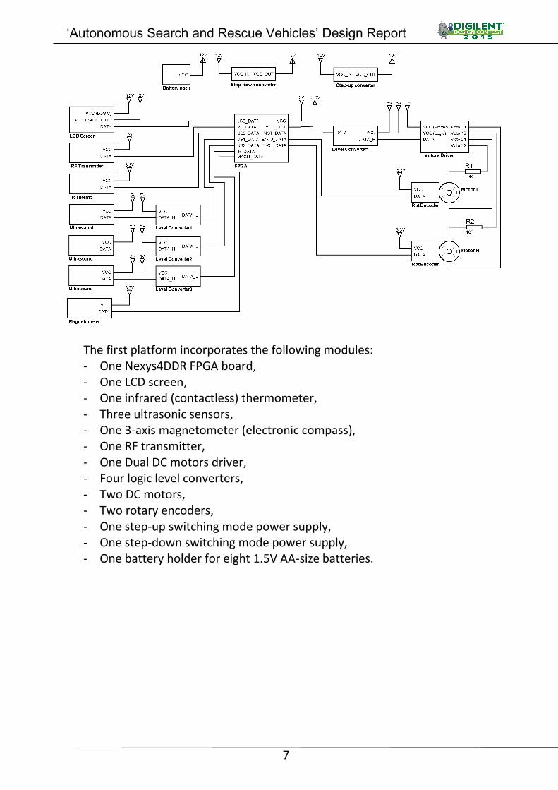
The first platform incorporates the following modules: - One Nexys4DDR FPGA board, - One LCD screen, - One infrared (contactless) thermometer, - Three ultrasonic sensors, - One 3-axis magnetometer (electronic compass), - One RF transmitter, - One Dual DC motors driver, - Four logic level converters, - Two DC motors, - Two rotary encoders, - One step-up switching mode power supply, - One step-down switching mode power supply, - One battery holder for eight 1.5V AA-size batteries.

‘Autonomous Search and Rescue Vehicles’ Design Report
8
2.1.1.1. Nexys4DDR FPGA board
The Nexys4DDR board is a development platform based on the Xilinx
XC7A100T-1CSG324C Artix-7 Field Programmable Gate Array (FPGA). Artix-7 100T features include: - 15,850 logic slices, each with four 6-input LUTs and 8 flip-flops, - 4,860 Kbits of fast block RAM, - Six clock management tiles, each phase-locked loop (PLL), - 240 DSP slices, - Internal clock speeds exceeding 450 MHz, - On-chip analog-to-digital converter (XADC).
The Nexys4 DDR board offers the following ports and peripherals: - 16 user switches, - 16 user LEDs, - Two 4-digit 7-segment displays, - USB-UART Bridge, - Two tri-color LEDs, - Micro SD card connector, - 12-bit VGA output, - PWM audio output, - PDM microphone, - 3-axis accelerometer, - Temperature sensor, - 10/100 Ethernet PHY, - 128MiB DDR2, - Serial Flash, - Four Pmod ports (with 8 I/Os per port), - Pmod for XADC signals (with 4 differential inputs), - USB-JTAG port (for FPGA programming and communication), - USB HID Host for mice, keyboards (and memory sticks for configuration).

‘Autonomous Search and Rescue Vehicles’ Design Report
9
This board is used as the main controller in the project, centralizing the input data (from the ultrasound modules, magnetometer, infrared sensor, rotary encoders) and controlling the output peripherals (LCD, motor driver, the second platform via radio communication). Also, the on-board buttons, switches and ambient thermometer are included in the design.
2.1.1.2. Mobile platforms
Both mobile platforms were acquired as a kit, and included the main Plexiglas
support board, two DC motor-driven wheels (with fixing brackets), and also a third passive wheel.
The multi-layer structure was obtained using ordinary PCB cooper boards (due to their availability, price, and added use as a ground plane).
2.1.1.3. LCD Screen
The HannStar Display HSD043I9W1-A is a color active matrix thin film
transistor (TFT) liquid crystal display (LCD). This module is composed of a TFT LCD panel, a driving circuit and a back light system. It has a 4.3 (16:9) display area with WQVGA (480 horizontal by 272 vertical pixel) resolution. RGB data is inputted via parallel 24-bit (8-bit per colour) and sync (control) signals can be either via Horizontal Sync/Vertical Sync (as used in the VGA interface), or using DataEnable/DataClock (where DataEnable is high when the display is in its active
‘Autonomous Search and Rescue Vehicles’ Design Report
10
area, with the DataClock at 10MHz). It was salvaged from a defective GPS navigator (as noticed by its branded plastic frame).
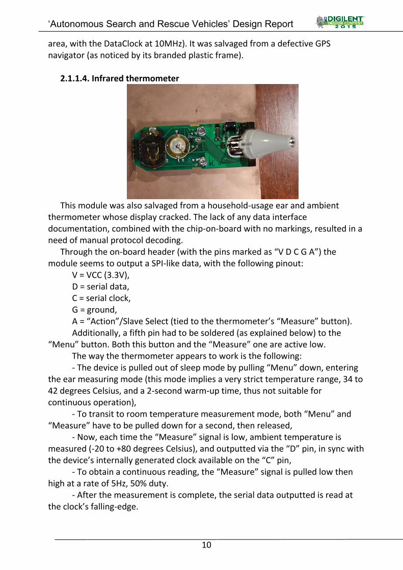
2.1.1.4. Infrared thermometer
This module was also salvaged from a household-usage ear and ambient
thermometer whose display cracked. The lack of any data interface documentation, combined with the chip-on-board with no markings, resulted in a need of manual protocol decoding.
Through the on-board header (with the pins marked as “V D C G A”) the module seems to output a SPI-like data, with the following pinout:
V = VCC (3.3V), D = serial data, C = serial clock, G = ground, A = “Action”/Slave Select (tied to the thermometer’s “Measure” button). Additionally, a fifth pin had to be soldered (as explained below) to the
“Menu” button. Both this button and the “Measure” one are active low. The way the thermometer appears to work is the following: - The device is pulled out of sleep mode by pulling “Menu” down, entering
the ear measuring mode (this mode implies a very strict temperature range, 34 to 42 degrees Celsius, and a 2-second warm-up time, thus not suitable for continuous operation),
- To transit to room temperature measurement mode, both “Menu” and “Measure” have to be pulled down for a second, then released,
- Now, each time the “Measure” signal is low, ambient temperature is measured (-20 to +80 degrees Celsius), and outputted via the “D” pin, in sync with the device’s internally generated clock available on the “C” pin,
- To obtain a continuous reading, the “Measure” signal is pulled low then high at a rate of 5Hz, 50% duty.
- After the measurement is complete, the serial data outputted is read at the clock’s falling-edge.

‘Autonomous Search and Rescue Vehicles’ Design Report
11
Each measurement cycle outputs a 40-bit serial data string, composed of the following 8-bit words:
0x5B t1t2 t3t4 checksum 0x0D Where the 4-bit words t1, t2, t3 and t4, when converted from hex to char
results in t1=tens of degrees, t2=degrees, t3=1/10 degrees, t4=1/100 degrees Celsius. Checksum is the binary sum of the first 24 bits, and 0x5B and 0x0D represents the start and ending markers for the data stream.
2.1.1.5. Ultrasonic sensor
The HC-SR04 Ultrasonic ranging module provides 2cm - 400cm non-contact
distance measurement function, with accuracy of up to 3mm. The module includes ultrasonic transmitter, receiver and control circuit.
To measure distance, the following protocol had to be implemented: “Trigger” pin is pulled high for 10us, the module sends eight 40 kHz pulses, and after the module receives the pulses signal back, it pulls the “Echo” pin high for a set time of 1uS per 58 centimeters in measured distance. 2.1.1.6. Magnetometer
In order to eliminate mechanical drift while the first platform moves
forward or backward, and also enable precise measurement and control of angle of rotation while the platform turn left, right or 180 degrees, an HMC5883L 3-axis magnetometer (or digital compass) was integrated in the design.
‘Autonomous Search and Rescue Vehicles’ Design Report
12
By measuring the magnetic field strength on the X and Y axis, and applying an arctan2() operation (also known as arctan(x/y)), a magnetic north heading can be calculated.
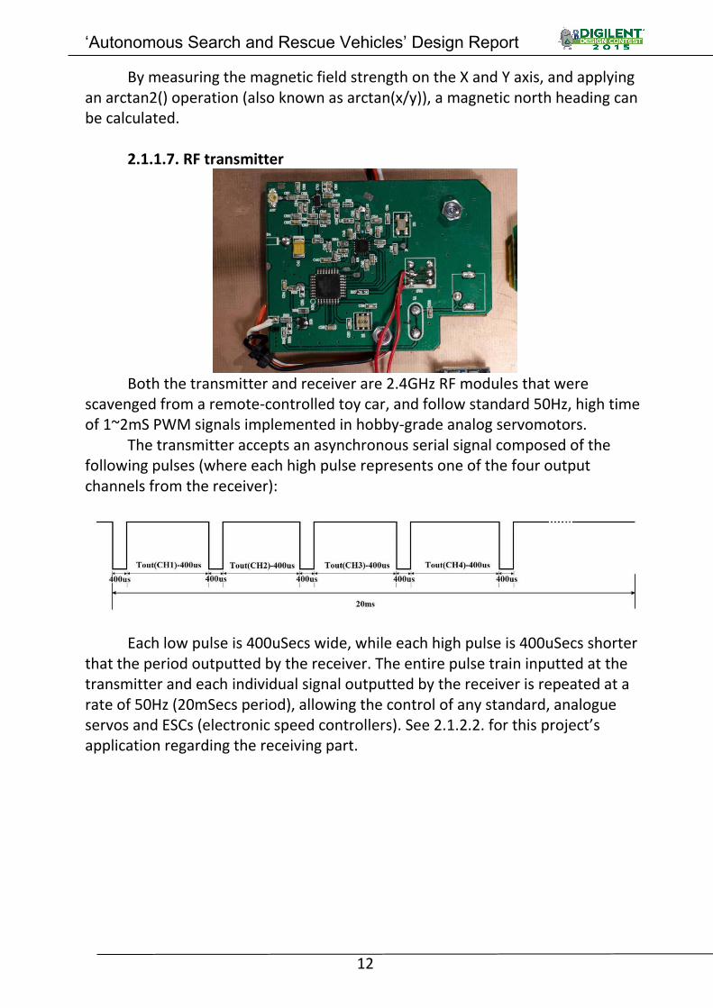
2.1.1.7. RF transmitter
Both the transmitter and receiver are 2.4GHz RF modules that were
scavenged from a remote-controlled toy car, and follow standard 50Hz, high time of 1~2mS PWM signals implemented in hobby-grade analog servomotors.
The transmitter accepts an asynchronous serial signal composed of the following pulses (where each high pulse represents one of the four output channels from the receiver):
Each low pulse is 400uSecs wide, while each high pulse is 400uSecs shorter
that the period outputted by the receiver. The entire pulse train inputted at the transmitter and each individual signal outputted by the receiver is repeated at a rate of 50Hz (20mSecs period), allowing the control of any standard, analogue servos and ESCs (electronic speed controllers). See 2.1.2.2. for this project’s application regarding the receiving part.

‘Autonomous Search and Rescue Vehicles’ Design Report
13
2.1.1.8. Dual DC motor driver
This dual bidirectional motor driver is based on the L298 dual H-bridge
motor driver integrated circuit. The circuit allows the state and direction control of two motors of 5~35V, up to 2A each (total power is limited at 25W). Logic is supplied at a 5V level, and includes an Enable, and two signals for motor drive polarity control, as depicted in its internal schematic:
On both outputs, a 10Ohm, 5W power resistor limits the current sourced by
the driver to about 1A per motor, for over-current protection.

‘Autonomous Search and Rescue Vehicles’ Design Report
14
2.1.1.9. Logic level converter
The JY-MCU is a 4-way bi-directional MOS-FET-based level converter. The
low-level reference voltage is supplied by an on-board 3V3 voltage regulator, which in turn is powered from the high-level reference voltage (in this case 5V).
2.1.1.10. Rotary Encoders
These components are standard 24-steps per revolution passive rotary
encoders, used to provide the number of full or partial rotation of each of the two wheels, allowing a measurement of distance travelled by them on the ground.
2.1.1.11. Miscellaneous modules Step-up switching-mode power supply (SMPS): powered by an XLSemi
XL6009 400kHz 60V 4A Boost DC-DC converter, this module supplies the required 19V voltage rail for the LCD screen’s backlighting system.
Step-down SMPS: a TI LM2596-based 150kHz 40V 3A Buck DC-DC converter, this module supplies the required 5V voltage rail for the Nexys4 board, ultrasound modules, motor driver logic and RF transmitter. The board incorporates a microcontroller-driven constant-current sourcing control (besides the standard constant-voltage mode).
‘Autonomous Search and Rescue Vehicles’ Design Report
15
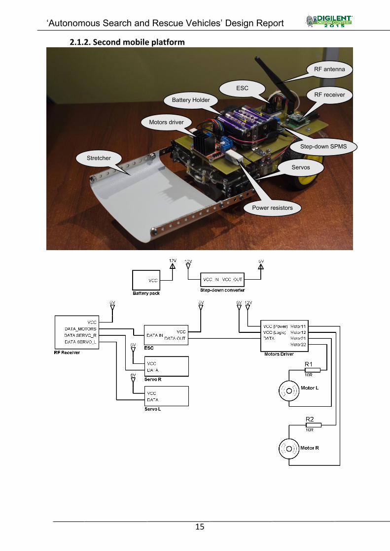
2.1.2. Second mobile platform
RF receiver ESC
RF antenna
Servos
Stretcher
Motors driver
Step-down SPMS
Battery Holder
Power resistors

‘Autonomous Search and Rescue Vehicles’ Design Report
16
The second platform consists of: - One electronic speed controller (ESC), - One RF receiver and PWM driver module, - One Dual DC motors driver, - Two servomotors (which power a makeshift stretcher), - Two DC motors, - One step-down switching mode power supply , - One battery holder for eight 1.5V AA-size batteries.
2.1.2.1. ESC
This is a low-entry, hobby-level, microcontroller-powered, ESC (electronic
speed controller) that convert two 50Hz PWM signals (correspondent to throttle and direction) into the six signals necessary for the motor driver. It allows us to interface the simple L298 H-bridge to the RF receiver (see 2.1.2.2. below).
2.1.2.2. RF Receiver
This receiver converts the signal received into four separate channels,
implementing the 50Hz, 1 to 2ms high time PWM. For the present project, on the first two channels an ESC is connected, while on the other two 1.1~1.9ms servo are used. The ESC uses the first channel for the throttle (1.1ms = full backwards, 1.5ms = stop, and 1.9ms = full forwards), and the second channel for direction (1.1ms = full left, 1.5ms = centered, and 1.9ms = full right). Thus, when the

‘Autonomous Search and Rescue Vehicles’ Design Report
17
throttle is at 1.5ms, the motors rotate in opposite directions, according to the second channel, allowing the target mobile platform to rotate on the spot. The Servos are mirror mounted, so the pulse widths are also mirrored at 1.5ms (1.5ms pulse width sets the servos to the center position).
2.1.2.3. Servomotors
This PWM-commanded servos incorporates an analog feedback circuit in order
to maintain their position even under load. They allow the modification of the make-shift stretcher’s angle in order to pick-up the ‘victim’.
2.1.2.4. Miscellaneous modules Step-down SMPS: similar to the buck converter used on the other platform,
it also uses the same LM2596 switching-mode voltage regulator, but does not include a current limiting capability.

‘Autonomous Search and Rescue Vehicles’ Design Report
18
2.2. Software Theory of operation - the first platform (main platform) will autonomously traverse (the “search” phase) an area randomly riddled with obstacles in search of the target (“victim” – a hands warmer). Once the target has been found (using the IR thermometer), the direct route back to the starting point will be calculated and then traversed by the second platform, without any sensory aid. Once it too will reach the target, it will pick-up the target, (the “rescue” phase).
Before we implement the main logic (searching for, and rescuing the target), we need to interface to the hardware modules presented at chapter 2.1.. For this, a VHDL module (stand-alone source file) was made for each peripheral, allowing future use in other projects, due to their universal usability.
Almost all processes implemented in this design check the synchronous active-high signal ‘reset_in’, in order to reset all of the variables and signals used. This signal is routed through a deabouncing moduel from the Nexys4DDR on-board’s button labeled ‘CPU_RESET’.
Where necessary, a clock divider was used to obtain a working frequency lower than the global clock that runs at 100MHz. The following dividing method (implemented as a process) is integrated throughout all applicable modules, where ‘x’ is the required frequency, and ‘max’ is the divider ratio, as follows:
max=(100.000.000/x)/2 – 1
This results a ‘clk_out’ clock signal with a fixed duty cycle of 50% percent. clk_div : process (clk100mhz_in)
variable count : integer range 0 to max; if (rising_edge(clk100mhz_in)) then if (reset_in = '1') then count := 0; clk_out <= '0'; else if (count = max) then count := 0; clk_out <= not clk_out; else count := count + 1; end if; end if; end if; end process clk_div;
The following sub-chapters document only the main, important parts of each VHDL module. For the complete source code, see sub-chapter 4.2, including the constraints file (at 4.2.12.) which notes the Nexys4DDR board pins and connections used in this project.

‘Autonomous Search and Rescue Vehicles’ Design Report
19
2.2.1. I2C bus master controller (i2c_master.vhd) The ambient thermometer and the magnetometer require an I2C master controller in order to allow communication between them and the FPGA chip. The following VHDL module is of general-use, and can send all the possible I2C master signals (Start, Restart, Stop, Write, Read with/without acknowledge), by controlling the SDA and SCL lines. Thus, it requires a top-level source to control it.
The SDA and SCL signals required I/O buffering at the top-level source file, and such the SDA/SCL in and out signals are declared and accessed separately at a module level, with the final input-output connection accomplished as follows:
sda_inout <= '0' when (sda_out='0') else 'Z'; scl_inout <= '0' when (scl_out='0') else 'Z'; sda_in <= sda_inout;
As the VHDL module consists of only one process, see sub-chapter 4.2. for the complete source code.
2.2.2. Nexys4DDR on-board peripherals 2.2.2.1. Buttons and switches (debouncer.vhd) To prevent any faulty operation due to erroneous user input interpretation
(input via either pressing a button or toggling a switch), a filter is needed to remove hardware ‘bouncing’ caused by imperfect electrical connection between contacts inside the buttons/switches. The bouncing phenomenon appears when state polling (checking the logic level – high/on, low/off) at a very high rate (in this case 100MHz), thus detecting all the small high-low signal transitions the contacts go through before they mechanically stabilize. This can be eliminated using a debouncing module: the switch or button is considered on (high) only when a certain time has passed with its logic state constant (high). For this project, 100ms are considered sufficient. To check the state and count at a rate of 1KHz (each 1 ms), an 100MHz-1KHz clock divider is used (resulting the ‘clk1khz’ signal). Btn_dbcd : process (clk1khz) variable count : integer range 0 to 100; begin if (rising_edge(clk1khz)) then if (btn_in = '1') then -- the input is high, count the time if (count = 100) then -- 100mSecs have passed, output high btn_out <= '1'; else -- continue counting count := count + 1; end if; else -- the input is low, reset the counter and output low count := 0; btn_out <= '0'; end if; end if; end process btn_dbcd;
All sixteen switches, five directional buttons (up, down, left, right, center),
and the CPU_RESET button use the same main logic for debouncing. For the directional buttons, in order to give a short pulse (instead of sending it high for as long as they are pressed), the following method was used: the state of each

‘Autonomous Search and Rescue Vehicles’ Design Report
20
buttons is saved at each global clock's rising edge, so that the output state will be high only when their debouncing process’s output signal logic state transitions from low (previous state) to high (current state), resulting in a 10nSec pulse (equal to the 100MHz global clock period): prev_buttons_state: process (clk100mhz_in) begin if (rising_edge(clk100mhz_in)) then btn_buff_4_prev <= btn_buff_4; -- save the values at rising edge btn_buff_3_prev <= btn_buff_3; btn_buff_2_prev <= btn_buff_2; btn_buff_1_prev <= btn_buff_1; btn_buff_0_prev <= btn_buff_0; end if; end process prev_buttons_state; btn_out_4 <= '1' when (btn_buff_4 = '1' and btn_buff_4_prev = '0') else '0'; btn_out_3 <= '1' when (btn_buff_3 = '1' and btn_buff_3_prev = '0') else '0'; btn_out_2 <= '1' when (btn_buff_2 = '1' and btn_buff_2_prev = '0') else '0'; btn_out_1 <= '1' when (btn_buff_1 = '1' and btn_buff_1_prev = '0') else '0'; btn_out_0 <= '1' when (btn_buff_0 = '1' and btn_buff_0_prev = '0') else '0';
2.2.2.2. Seven-segment LED displays (seven_seg_disp.vhd) The Nexys4DDR board has eight digits, seven segment per digit LED display,
with dot point inbetween digits, allowing visual representation of all possible hexadecimal characters (numbers 0~9, A, B, C, D, E, F):
According to the electrical connections on the Nexys4DDR (bipolar
transistors are used), both the anode and cathode signals are active-low. In the following process, the ‘cat_out’ vector contains the state of the
seven segments, as follows: g,f,e,d,c,b,a. process (clk1khz) is
variable digit : integer range 0 to 7; variable value : std_logic_vector (3 downto 0); begin if (rising_edge(clk1khz)) then case (digit) is
-- each of the 8 digits and their respective 4-bit data are selected in succession when 0 =>
-- the digits are numbered from 0 to 7, with the hardware equivalence of 0 = right-most, 7 = left-most dp_out <= '1'; -- there is a digit point in-between each two digits an_out <= "11111110"; value := data_in(3 downto 0);
-- the data-in vector contains all the 8 4-bit data groups, with digit 7 downto 0 when 1 => dp_out <= '1'; an_out <= "11111101"; value := data_in(7 downto 4); when 2 => dp_out <= '0';

‘Autonomous Search and Rescue Vehicles’ Design Report
21
an_out <= "11111011"; value := data_in(11 downto 8); when 3 => dp_out <= '1'; an_out <= "11110111"; value := data_in(15 downto 12); when 4 => dp_out <= '0'; an_out <= "11101111"; value := data_in(19 downto 16); when 5 => dp_out <= '1'; an_out <= "11011111"; value := data_in(23 downto 20); when 6 => dp_out <= '0'; an_out <= "10111111"; value := data_in(27 downto 24); when 7 => dp_out <= '1'; an_out <= "01111111"; value := data_in(31 downto 28); end case; case (value) is
-- depending on the 4-bit-BCD-coded data selected for the present digit, the segments are lit in order to represent all 16 possible characters when "0000" => cat_out <="1000000"; -- 0 when "0001" => cat_out <="1111001"; -- 1 when "0010" => cat_out <="0100100"; -- 2 when "0011" => cat_out <="0110000"; -- 3 when "0100" => cat_out <="0011001"; -- 4 when "0101" => cat_out <="0010010"; -- 5 when "0110" => cat_out <="0000010"; -- 6 when "0111" => cat_out <="1111000"; -- 7 when "1000" => cat_out <="0000000"; -- 8 when "1001" => cat_out <="0010000"; -- 9 when "1010" => cat_out <="0001000"; -- A when "1011" => cat_out <="0100000"; -- B when "1100" => cat_out <="1000110"; -- C when "1101" => cat_out <="1100000"; -- D when "1110" => cat_out <="0000110"; -- E when "1111" => cat_out <="0001110"; -- F end case; if (digit = 7) then -- if at the last digit, start again digit := 0; else digit := digit + 1; end if; end if; end process;
2.2.2.3. Ambient thermometer (ambient_thermo.vhd)
As described before, to accurately discriminate the floor temperature against the hands warmer (or ‘victim’, target), regardless of the area the project is run, the ambient is measured using the on-board Analog Devices ADT7420 temperature sensor. The I2C interface communication is accomplished via the I2C master controller module described before, using the following operations:
1. Start, 2. Write 10010110 – write request (1001011 is the ADT7420 I2C address,
LSB='1' equals register reading, LSB='0' equals writing) 3. Write 00000000 - Targeted starting register (0x00 - temperature MSB),

‘Autonomous Search and Rescue Vehicles’ Design Report
22
4. Restart, 5. Write 10010111 -- Read request,
6. ReadACK -- Read temperature MSB register, send acknowledge, 7. ReadNACK -- Read temperature LSB register, don’t send acknowledge,
8. Stop. If after any of the write operations the controller modules does not receive the expected acknowledge response from the I2C slave, all the commands are resent for a maximum number of 10 times. 2.2.3. LCD screen (LCD.vhd)
For synching the LCD logic, two signals (DataEnable and DataClock) are to be sent synchronous with the RGB data stream. DataEnable is high when the horizontal and vertical display counters are in the active area, while DataClock is a constant 10MHz pulse. The required clock (‘clk10mhz’ signal) is generated using a clock divider process. To determine the correct active area dimensions, the following values are necessary for the counting processes:
constant h_active : integer := 480; -- horizontal active area (clock cycles) constant v_active : integer := 272; -- vertical active area constant h_max : integer := 544; -- horizontal maximum area constant v_max : integer := 307; -- vertical maximum area
This results in the following logic: lcd_de_out <= '1' when (h_counter<h_active and v_counter<v_active) else '0';
The following processes control the horizontal and vertical counters, incrementing at each 10MHz clock rising edge: h_count : process (clk10mhz) begin if (rising_edge(clk10mhz)) then if (reset_in = '1') then h_counter <= 0; else if(h_counter = h_max) then h_counter <= 0; else h_counter <= h_counter + 1; end if; end if; end if; end process h_count; v_count: process (clk10mhz) begin if (rising_edge(clk10mhz)) then if(reset_in = '1') then v_counter <= 0; else if(h_counter = h_max) then if(v_counter = v_max) then v_counter <= 0; else v_counter <= v_counter + 1; end if; end if; end if; end if;
end process v_count;

‘Autonomous Search and Rescue Vehicles’ Design Report
23
2.2.4. Infrared thermometer (ir_thermo.vhd) Each measurement cycle outputs a 40-bit serial data string, composed of
the following 8-bit words: 0x5B t1t2 t3t4 checksum 0x0D
Where the 4-bit words t1, t2, t3 and t4, when converted from hex to char results in t1=tens of degrees, t2=degrees, t3=1/10 degrees, t4=1/100 degrees Celsius. Checksum is the binary sum of the first 24 bits, and 0x5B and 0x0D represents the start and ending of the data stream.
The required clock for signaling the ‘measure’ button (see 2.1.1.4.), ‘clk5hz’, is generated using a clock divider process, with the following additions for controlling the ‘menu’ signal as well:
process (clk100mhz_in) is variable count: integer range 0 to 9999999;
variable cycles : integer range 0 to 3; begin
if (rising_edge(clk100mhz_in)) then if (reset_in = '1') then count := 0; clk5hz <= '1'; power_out <= '1'; cycles := 0; else if (count = 9999999) then clk5hz <= not clk5hz; count := 0; if (cycles /= 2) then -- to pulse the "Menu" button power_out <= not power_out; cycles := cycles + 1; end if; else count := count + 1; end if; end if; end if; end process;
For the actual data acquisition from the sensor: process (clock_in) is – ‘clock_in’ is the clock generated by the thermometer variable count : integer range 0 to 40; variable data : std_logic_vector (0 to 31); begin
if (falling_edge(clock_in)) then if (reset_in = '1') then count := 0; data := (others => '0'); data_out <= (others => '0'); done_out <= '1'; else if (count = 39) then -- check checksum before outputting if (std_logic_vector(unsigned(data(0 to 7)) +
unsigned(data(8 to 15)) + unsigned(data(16 to 23))) = data(24 to 31)) then data_out <= data (8 to 23); done_out <= '1'; else data_out <= (others => '0'); end if; count := 0; else done_out <= '0'; if (count < 32) then -- only useful data bits data(count) := irtmp_miso_in; end if;

‘Autonomous Search and Rescue Vehicles’ Design Report
24
count := count + 1; end if; end if;
end if; end process;
2.2.5. Ultrasound sensors (ultrasound.vhd) To measure distance, the following protocol had to be implemented: - “Trigger” pin is pulled high for 10us, - wait for the “Echo” pin to be high, - measure the time until ‘Echo’ is low again. To accurately measure the ‘echo’ time period in resolution of 1usecond, an
clock divider to 1MHz was necessary (‘clk1mhz’). ultrasound_ctrl : process (clk1mhz)
-- 'chip select' - each sensor is selected in succession variable cs : std_logic_vector (2 downto 0) := "001";
-- internal state for each sensor (trigger set, echo received) variable triggered, echoed : std_logic := '0';
-- period of time the sensor returned variable period : integer range 0 to 32767 := 0;
-- to send a 10usec trigger signal, a counter is used (10 1MHz cycles) variable count : integer range 0 to 10 := 0;
-- sensor number (to assign measurement data to the respective sensor) variable nr : integer range 0 to 2 := 0; begin if (rising_edge(clk1mhz)) then if (done = '0') then -- if not done, continue the state machine if (triggered = '0') then -- trigger not sent yet if (count = 10) then -- 10uSecs passed, go to echo measurement phase us_trig_out <= "000"; count := 0; triggered := '1'; period := 0; echoed := '0'; else -- continue sending the trigger signal us_trig_out <= cs; count := count + 1; end if; else -- echo measurement if (us_echo_in = cs) then -- wait for the echo to get pulled up, signifying the start of the period measurement echoed := '1'; end if; if (echoed = '1') then if (us_echo_in = cs) then -- if the echo is still high, continue counting the uSecs if (period < 32767) then period := period + 1; end if; else -- done measuring, output the data if (period < 4095) then -- if distance is more than 4095/58=70cm, trim it to 12-bits data_buff(nr) <= std_logic_vector(to_unsigned(period,12)); -- output time period measured else data_buff(nr) <= (others => '1'); end if; echoed := '0'; triggered := '0';
-- to do each sensor in succession, bit-shifting was used if (cs = "100") then -- if last sensor nr := 0; cs := "001";

‘Autonomous Search and Rescue Vehicles’ Design Report
25
done <= '1'; else -- go to next sensor cs := cs(1 downto 0) & '0'; nr := nr + 1; end if; end if; end if; end if; end if; end if; end if; end process ultrasound_ctrl;
2.2.6. Magnetometer (magnetometer.vhd) Similarly to the ADT7420 ambient thermometer, this device also relies to an
I2C bus for communication, and thus requires the ‘i2c_master’ module. While the ADT7420 doesn’t require any registry change in order for it to continuously measure, the HMC5883L expects the following commands for it to output its measurement results (magnetic field strength on all three axes – X, Y, and Z):
a. One-time initialization: 1. Start, 2. Write 00111100 - write request (11110 is the HMC5883L I2C address,
LSB='1' equals register reading, LSB='0' equals writing), 3. Write 00000000 - targeted register (0x00 - samples averaging), 4. Write 01110000 - set sample averaging to 8x, 5. Restart, 6. Write 00111100 - write request, 7. Write 00000000 - targeted register (0x00 - samples averaging), 8. Restart, 9. Write 00111101 – read request, 10. ReadNACK - read samples averaging register, 11. Restart, 12. Write 00111100 - write request, 13. Write 00001010 - targeted register (0x0A - device ID), 14. Restart, 15. Write 00111101 – read request, 16. ReadACK - read first ID register, 17. ReadACK - read second ID register, 18. ReadNACK - read third ID register, 20. Stop. After the four registers are read, the values are compared to the datasheet
ones, and if equal, the initialization is considered complete. If not, the process retry all the commands above 10 times, then gives up. This initialization part was implemented in order to check for correct registry read and write operations.
b. Single-mode measurement: 1. Start,

‘Autonomous Search and Rescue Vehicles’ Design Report
26
2. Write 00111100 - write request, 3. Write 00000010 - targeted register (0x02 - measurement mode), 4. Write 00000001 - set measurement mode to single mode, 5. Stop, wait for 10ms or for HMC5883L’s Int (DataReady) pin to be low, 6. Start, 7. Write 00111100 - write request, 8. Write 00000000 - targeted register (0x03 - X axis MSB register), 9. Restart, 10. Write 00111101 – read request, 11. ReadACK - read X axis MSB register, 12. ReadACK - read X axis LSB register, 13. ReadACK - read Z axis MSB register, 14. ReadACK - read Z axis LSB register, 15. ReadACK - read Y axis MSB register, 16. ReadNACK - read Y axis LSB register, 17. Stop.
After the registries have been read, an arctan2() approximation is applied on the X and Y axis readings. In order to obtain an 0~360 degrees true north heading, we used the following integer-only algorithm, which yields an absolute error of +/- 2 heading degrees: x_abs = abs(x) y_abs = abs(y) if x_abs < y_abs then arctan2 = x_abs x_abs = y_abs y_abs = arctan2 flipped = 1 else flipped = 0 arctan2 = (30*x_abs)/y_abs if arctan2 == 0 then arctan2 = 90 elsif arctan2 > 81 then arctan2 = 1720/arctan2 else
arctan2 = 1720/(arctan2+8) if flipped == 1 then arctan2 = 90-arctan2 if x < 0 then if y < 0 then arctan2 = 180 + arctan2 else arctan2 = 180 – arctan2 else if y < 0 then arctan2 = 360 – arctan2
2.2.7. RF Transmitter (rf_motor_driver.vhd)
Following the description for the transmitter (see 2.1.1.7.) and the application for the receiver (see 2.1.2.2.), the following module creates and sends (via serial shifting) the required pulse train, in accordance to the motors direction and servos position requested by the top-level source (via the ‘dir_in’ signal):
‘Autonomous Search and Rescue Vehicles’ Design Report
27
pulse_gen : process (clk100mhz_in) variable data_out_buff : std_logic_vector (199 downto 0); -- buffer for the 200-bit output vector variable counter : integer range 0 to 29_000_000 := 29_000_000; -- counter for the time delay variable index : integer range 0 to 195; -- overall index variable index1, index2 : integer range 7 to 16 := 11; -- index(length) for the first and second channel variable index3 : integer range 10 to 14 := 11; -- index for the third channel variable index4 : integer range 8 to 12 := 11; -- index for the fourth channel variable step : integer range 0 to 3 := 0; -- internal state machine counter begin if (rising_edge(clk100mhz_in)) then if (done = '0') then -- if not done, continue the state machine case (step) is when 0 => case (dir_in(4 downto 2)) is -- the first (MSB) three bits decide the direction when "100" => -- rotate left index1 := 7; index2 := 11; counter := 19_000_000; -- rotation requires (100.000.000/19.000.000=) 190mSecs to complete when "001" => -- rotate right index1 := 15; index2 := 11; counter := 19_000_000; when "101" => -- go forwards index1 := 11; index2 := 15; counter := 29_000_000; -- going forward/backward requires 290mSecs to complete when "010" => -- go backwards index1 := 11; index2 := 7; counter := 29000000; when others => -- stop index1 := 11; index2 := 11; end case; case (dir_in(1 downto 0)) is -- the last (LSB) two bits decide the servos position when "01" => -- downwards index3 := 10; index4 := 12; when "10" => -- upwards index3 := 14; index4 := 8; when others => -- centred index3 := 11; index4 := 11; end case; step := 1; when 1 => -- generate the signal, using the four index values set at step 0 data_out_buff := (others => '0'); index := 195; data_out_buff (index downto 0) := (others => '1'); index := index - index1; data_out_buff (index downto 0) := (others => '0'); index := index - 4; data_out_buff (index downto 0) := (others => '1'); index := index - index2; data_out_buff (index downto 0) := (others => '0'); index := index - 4; data_out_buff (index downto 0) := (others => '1'); index := index - index3; data_out_buff (index downto 0) := (others => '0'); index := index - 4;

‘Autonomous Search and Rescue Vehicles’ Design Report
28
data_out_buff (index downto 0) := (others => '1'); index := index - index4; data_out_buff (index downto 0) := (others => '0'); index := index - 4; data_out_buff (index downto 0) := (others => '1'); data_out <= data_out_buff; if (counter /= 0) then step := 2; -- after the pulse train is sent, wait for the amount time required else step := 3; -- the wait period end if; when 2 => -- wait for the set amount of time if (counter = 0) then index1 := 11; -- after waiting, set the two channels back to their centre values index2 := 11; -- thus, the platform will stop step := 1; -- redo the pulse train with the new values else counter := counter - 1; end if; when 3 => -- wait for the pulse train to be sent if (bit_count = 0) then done <= '1'; -- sending done step := 0; end if; end case; end if; end if; end process pulse_gen; data_shift : process (clk10khz) -- serially shift the state vector indefinitely begin if (rising_edge(clk10khz)) then if (reset_in = '1') then bit_count <= 199; else rf_data_out <= data_out(bit_count); if (bit_count = 0) then bit_count <= 199; else bit_count <= bit_count - 1; end if; end if; end if; end process data_shift;
2.2.8. Motors driver (motor_driver.vhd)
For the first mobile to move forward/backward in a straight trajectory and a fixed distance, and also rotate left/right as close to 90 degrees as possible, this VHDL module integrates the ‘magnetometer’ module in order to measure the angle of rotation. It also reads the outputs from the rotary encoders that are mechanically connected to the wheels shaft. For complete code, please see sub-chapter 4.2.

‘Autonomous Search and Rescue Vehicles’ Design Report
29
2.2.9. Top-level module (top_module.vhd) By far the most complex, this module integrates all the other ones in order to accomplish this project’s required steps. It controls all the hardware peripherals, and implements the mapping logic, as described below.
The main state machine incorporated in this module makes use of two data storage, implemented as Block-RAMs: RAM1 and RAM2.
RAM1 is used to display (see 'lcd_disp' process) the trace done and obstacles found while the platform is moving, ant thus has 272-by-480 positions (equivalent to the LCD screen resolution, for faster ‘drawing’ and displaying). Each position contains 2 bits (bit1 (MSB) = obstacle, bit0 (LSB) = trace), and is physically equivalent to a 25-by-25 cm block on the search area.
For easier access, RAM2 is used to represent the working area in blocks (addresses), resulting in 10-by-18 positions. Each position contains 4 bits (bit3 (MSB) = obstacle, bit2 = trace, bits1 and 0 (LSB) = heading if trace).
Both BRAMs are implemented using one-dimensional addressing, but the actual access and interpretation is accomplished using two dimensions (v_index = vertical, h_index = horizontal), with the dimensional conversion made via the 'ram_h_v_to_addr_and_writer' process. Thus, for RAM2, to go to a next (2-D) line, add 18 to the address, subtract 18 to go to previous. To go to a next (2-D) column add 1, previous subtract 1. For RAM1, add or subtract 480 for line jump, add or subtract 1 for column jump.
The physical search area (480*272cm) is represented on RAM2 as follows:
During the search phase of the project, a two-step state-machine was implemented, which consists of A. obstacle check (if physical obstacles are in front of the platform) and B. trace check (if the platform already was on the position in front):

‘Autonomous Search and Rescue Vehicles’ Design Report
30
For the complete source code, see sub-chapter 4.2. below.

‘Autonomous Search and Rescue Vehicles’ Design Report
31
3. Discussion 3.1. Resource requirements To run the project, an area of at least 480-by-272 cm is necessary. The
‘victim’ (or target), although described in this report as a hands warmer, can be any object that emanates a temperature of at least 15 degrees Celsius above room temperature, and which can be picked using the second platform’s stretcher. Finally, objects that are taller than 10cm and wider than 25cm can be used as obstacles inside the search area.
Regarding the software design, by generating the required bitstream file (to program the Nexys4DDR’s on-board FPGA chip), including all the source codes described above, Xilinx’s Vivado v2014.4 suite implements it using the following Artix7 XC7A100T FPGA resources:
Resource Utilization Available Utilization (%) FF (flip-flop) 1258 126800 0,99
LUT (look-up table) 2968 63400 4,68 I/O (input/output) 95 210 45,24
BRAM (block—RAM) 8,50 135 6,30
DSP48 (digital signal processor) 1 240 0,42 BUFG (global buffer) 6 32 18,75
This results in the following performances: - Worst negative slack: 0.509ns, - Worst hold slack: 0.108ns, - Worst pulse width slack: 4.5ns, - Total on-chip power: 0.159W (0.054W dynamic, 0.105W device static), - Junction temperature: 25,7 degrees Celsius, Overall summary: 0 errors, 0 critical warnings, 20 warnings, 0 advisories. 3.2. Problems encountered Although multiple corrections are made to assure precise movement (by
using rotary encoders to count the steps each wheel made, and an magnetometer to get a true north heading, allowing the measurement of the angle of rotation), the first platform still presents errors due to its construction (two active wheels, one passive wheel). Also, as the second platform, by design, lacks any feedback/corrections mechanisms, it will too occasionally have unpredictable behavior. As possible solutions, there are: changing the motor feedback, the motors themselves or the mobile platform as a whole (instead of two active wheel, there are other platforms that have four ones).
One of the biggest (or longest time to resolve) issue that we had during software development was integrating the arctan2() operator. Although the Vivado suite includes a trigonometric library, the respective library utilizes a variable type (‘real’) that is not synthesizable (can only be used in simulation, not on physical FPGA hardware). Although algorithms and third-party libraries are

‘Autonomous Search and Rescue Vehicles’ Design Report
32
freely available, those proved too complicated (and unused to their full potential) for our application - getting an 0~360 degrees true north heading in 1 degree resolution. Thus, after a long research time (in the order of days), we ended up implementing the integer-only algorithm described at sub-chapter 2.2.5..
4. References 4.1. External documentation
- Digilent Nexys4DDR reference manual (http://digilentinc.com/Data/Products/NEXYS4DDR/Nexys4-DDR_rm.pdf),
- Digilent Nexys4DDR board schematics (http://digilentinc.com/Data/Products/NEXYS4DDR/Nexys4-DDR_sch.PDF), - Vivado Design Suite Synthesis User Guide (http://www.xilinx.com/support/documentation/sw_manuals/xilinx2014_1/ug901-vivado-synthesis.pdf), - Analog Devices ADT7420 datasheet (http://www.analog.com/media/en/technical-documentation/data-sheets/ADT7420.pdf), - HannStar Display HSD043I9W1-A datasheet (https://www.eltech.spb.ru/files/item/HSD043I9W1.pdf), - Honeywell HMC5883L datasheet (http://www51.honeywell.com/aero/common/documents/myaerospacecatalog-documents/Defense_Brochures-documents/HMC5883L_3-Axis_Digital_Compass_IC.pdf), - HC-SR04 datasheet (http://www.micropik.com/PDF/HCSR04.pdf), - STMicroelectronics Instruments L298 datasheet (http://www.st.com/web/en/resource/technical/document/datasheet/CD00000240.pdf), - STMicroelectronics L298 motors driver module schematic (http://www.electrotec.pe/media/Productos/Driver%20dual%20para%20motores%20con%20L298N/PNG5.png), - RF transmitter/receiver user manual (https://www.scribd.com/doc/24722644/R-C-System-ETB41-2-4GHz-ART-TECH-English).

‘Autonomous Search and Rescue Vehicles’ Design Report
33
4.2. Source code 4.2.1. ambient_thermo.vhd ---------------------------------------------------------------------------------------------------- ---- TITLE: Analog Devices ADT7420 I2C ambient thermometer interfacer (ambient_thermo.vhd) ---- REVISION: 1.0 (10.05.2015) ---- DEPENDENCIES: I2C Master Controller (i2c_master.vhd) ---- REQUIRENMENTS: SDA and SCL I/O buffers on the top-level source (see top_module.vhd) ---- DEVICE, ENVIRONMENT: Digilent Nexys4DDR, Xilinx Vivado 2014.4 ---- CONTACT: Pop Mihnea Vlad ([email protected]), Tatar Alex ([email protected]) ---------------------------------------------------------------------------------------------------- ---- DESCRIPTION: This module allows the reading of ADT7420's two 8-bit temperature registers ---------------------------------------------------------------------------------------------------- library ieee; use ieee.std_logic_1164.all; entity ambient_thermo is port ( clk100mhz_in : in std_logic; -- 100MHz global clock reset_in : in std_logic; -- active-high start_in : in std_logic; -- active-high done_out : out std_logic; -- active-high data_out : out std_logic_vector(15 downto 0); -- 16-bit data from the two 8-bit registers tmp_sda_in : in std_logic; -- SDA input* tmp_sda_out : out std_logic; -- SDA output* tmp_scl_out : out std_logic); -- SCL output end ambient_thermo; -- * although the SDA line is bidirectional, input and output signals are separated so that the I/O buffering is accomplished inside the top-level source architecture behavioral of ambient_thermo is component i2c_master is -- for the actual I2C SDA and SCL lines control, the i2c_master module is used (see i2c_master.vhd for more info) port ( clk100mhz_in : in std_logic; reset_in : in std_logic; oper_in : in std_logic_vector(2 downto 0); en_in : in std_logic; done_out : out std_logic; ack_out : out std_logic; data_in: in std_logic_vector(7 downto 0); data_out: out std_logic_vector(7 downto 0); sda_in : in std_logic; sda_out : out std_logic; scl_out: out std_logic); end component; -- for universal interfacing to the i2c_master, the op_type signal is converted to std_logic_vector, allowing easier component port signals declarations (see the with..select command bellow) type op_type is (i2c_start, i2c_restart, i2c_write, i2c_read_ack, i2c_read_nack, i2c_stop); -- I2C master states signal i2c_op : op_type := i2c_start; signal i2c_oper : std_logic_vector (2 downto 0) := "001"; signal i2c_en, i2c_done, i2c_ack : std_logic; -- status signals inputted/outputted from the i2c_master module signal done : std_logic := '1'; -- signals that this module has finished reading the registers and data_out is refreshed signal i2c_data_in, i2c_data_out : std_logic_vector(7 downto 0) := (others => '0'); -- I2C interface 8-bit inputted (from slave to master) and outputted (from master to slave) signal state : integer range 0 to 11 := 0; -- internal state machine counter begin i2c_master_module : i2c_master port map (clk100mhz_in, reset_in, i2c_oper, i2c_en, i2c_done, i2c_ack, i2c_data_out, i2c_data_in, tmp_sda_in, tmp_sda_out, tmp_scl_out); -- component instantiation with i2c_op select i2c_oper <= "001" when i2c_start, "011" when i2c_restart, "010" when i2c_write, "110" when i2c_read_ack, "100" when i2c_read_nack, "000" when i2c_stop; -- converts op_type to std_logic_vector done_out <= done; -- connects the internal 'done' signal to the module output 'done_out'

‘Autonomous Search and Rescue Vehicles’ Design Report
34
amb_thermo_i2c_ctrl: process (clk100mhz_in) variable error_count : integer range 0 to 10; -- counts the number of I2C acknowledge errors begin if (rising_edge(clk100mhz_in)) then if (reset_in = '1') then -- resets all signals used by this process done <= '1'; i2c_en <= '0'; i2c_op <= i2c_start; i2c_data_out <= (others => '0'); data_out <= (others => '0'); state <= 0; error_count := 0; else if (start_in = '1' and done = '1') then -- if done, wait for the start signal done <= '0'; elsif (done = '0') then -- if not done, continue the state machine if (i2c_en = '1') then -- the i2c_en signal needs to be a one-shot for each operation i2c_en <= '0'; elsif (i2c_done='1') then -- wait for i2c_master to finish case state is when 0 => -- START operation i2c_op <= i2c_start; state <= 1; when 1 => -- WRITE operation (1001011 is the ADT7420 I2C address, LSB bit is the operation requested) i2c_op <= i2c_write; i2c_data_out <= "10010110"; state <= 2; when 2 => -- Targeted starting register (0x00 - temperature MSB) if (i2c_ack = '0') then -- continue if the slave acknowledge correctly, else restart i2c_op <= i2c_write; i2c_data_out <= "00000000"; state <= 3; else state <= 11; end if; when 3 => -- Restart operation if (i2c_ack = '0') then i2c_op <= i2c_restart; state <= 4; else state <= 11; end if; when 4 => -- Read operation (LSB='1' equals register reading, LSB='0' equals writing) i2c_op <= i2c_write; i2c_data_out <= "10010111"; state <= 5; when 5 => -- Read register if (i2c_ack = '0') then i2c_op <= i2c_read_ack; state <= 6; else state <= 11; end if; when 6 => -- MSB register read data_out(15 downto 8) <= i2c_data_in; state <= 7; when 7 => i2c_op <= i2c_read_nack; state <= 8; when 8 => -- LSB register read

‘Autonomous Search and Rescue Vehicles’ Design Report
35
data_out(7 downto 0) <= i2c_data_in; state <= 9; when 9 => -- Stop i2c_op <= i2c_stop; state <= 10; when 10 => -- Done registers reading state <= 0; done <= '1'; when others => -- Acknowledge error (the SDA line was not pulled low) i2c_op <= i2c_stop; state <= 0; if (error_count = 10) then -- try 10 times, then give up error_count:=0; done <= '1'; else error_count := error_count + 1; end if; end case; if (state /= 6 and state /= 8 and state /= 10) then -- set the i2c_en high only when a I2C operation is required i2c_en <= '1'; end if; end if; end if; end if; end if; end process amb_thermo_i2c_ctrl; end behavioral;
4.2.2. debouncer.vhd ---------------------------------------------------------------------------------------------------- ---- TITLE: Switches and buttons debouncer (debouncer.vhd) ---- REVISION: 1.0 (10.05.2015) ---- DEPENDENCIES: None ---- REQUIRENMENTS: None ---- DEVICE, ENVIRONMENT: Digilent Nexys4DDR, Xilinx Vivado 2014.4 ---- CONTACT: Pop Mihnea Vlad ([email protected]), Tatar Alex ([email protected]) ---------------------------------------------------------------------------------------------------- ---- DESCRIPTION: This module debounces the inputs from the Nexys4 on-board switches and buttons -- (including the active-low CPU_RESET button, which is negated at the output) ---------------------------------------------------------------------------------------------------- library ieee; use ieee.std_logic_1164.all; entity debouncer is port ( clk100mhz_in : in std_logic; -- 100MHz global clock sw_in : in std_logic_vector (15 downto 0); -- active-high btn_in : in std_logic_vector (4 downto 0); -- active-high cpu_reset_in : in std_logic; -- active-low sw_out : out std_logic_vector (15 downto 0); -- active-high btn_out : out std_logic_vector (4 downto 0); -- active-high cpu_reset_out : out std_logic); -- active-high end debouncer; architecture behavioral of debouncer is signal clk1khz : std_logic; -- 1kHz internal clock to allow measurement of time in step of 1 mSec signal btn_buff_4, btn_buff_3, btn_buff_2, btn_buff_1, btn_buff_0 : std_logic := '0'; -- internal current buttons state s(low or high) signal btn_buff_4_prev, btn_buff_3_prev, btn_buff_2_prev, btn_buff_1_prev, btn_buff_0_prev : std_logic := '0'; -- internal previous buttons states
‘Autonomous Search and Rescue Vehicles’ Design Report
36
signal btn_out_4, btn_out_3, btn_out_2, btn_out_1, btn_out_0 : std_logic := '0'; -- output buttons states signal sw_out_15, sw_out_14, sw_out_13, sw_out_12, sw_out_11, sw_out_10, sw_out_9, sw_out_8, sw_out_7, sw_out_6, sw_out_5, sw_out_4, sw_out_3, sw_out_2, sw_out_1, sw_out_0 : std_logic := '0'; -- output switches states signal cpu_reset : std_logic := '0'; -- output CPU_RESET button state begin cpu_reset_out <= cpu_reset; btn_out <= btn_out_4 & btn_out_3 & btn_out_2 & btn_out_1 & btn_out_0; sw_out <= sw_out_15 & sw_out_14 & sw_out_13 & sw_out_12 & sw_out_11 & sw_out_10 & sw_out_9 & sw_out_8 & sw_out_7 & sw_out_6 & sw_out_5 & sw_out_4 & sw_out_3 & sw_out_2 & sw_out_1 & sw_out_0; -- in order for the buttons' output state to be a short one-shot pulse, the state of each buttons is saved at each global clock's rising edge, so that -- the output state will be high only when the state transitions for low (previous state) to high (current state), resulting in a 10nSec pulse (equal to the 100MHz global clock period) prev_buttons_state: process (clk100mhz_in) begin if (rising_edge(clk100mhz_in)) then btn_buff_4_prev <= btn_buff_4; btn_buff_3_prev <= btn_buff_3; btn_buff_2_prev <= btn_buff_2; btn_buff_1_prev <= btn_buff_1; btn_buff_0_prev <= btn_buff_0; end if; end process prev_buttons_state; btn_out_4 <= '1' when ((btn_buff_4 = '1') and (btn_buff_4_prev = '0')) else '0'; -- see notes above btn_out_3 <= '1' when ((btn_buff_3 = '1') and (btn_buff_3_prev = '0')) else '0'; btn_out_2 <= '1' when ((btn_buff_2 = '1') and (btn_buff_2_prev = '0')) else '0'; btn_out_1 <= '1' when ((btn_buff_1 = '1') and (btn_buff_1_prev = '0')) else '0'; btn_out_0 <= '1' when ((btn_buff_0 = '1') and (btn_buff_0_prev = '0')) else '0'; clk_div : process (clk100mhz_in) -- 100MHz to 1kHz, 50% duty cycle, clock divider variable count : integer range 0 to 49999; -- (100.000.000/1.000)/2 - 1 begin if (rising_edge(clk100mhz_in)) then if (count = 49999) then clk1khz <= not clk1khz; -- to obtain a 50% duty cycle, the clk1khz signal is negated at each 50.000 cycles (or 2kHz), resulting an 1kHz clock count := 0; else count := count + 1; end if; end if; end process clk_div; -- The following processes are one for each button and switch, and will set it's signal output state to high only when the input signal has been high for at least 100mSecs, else reset it to low, -- with the exception for the CPU_RESET button process, which outputs high when the input is low for the set amount of time cpu_reset_dbcd : process (clk1khz) variable count : integer range 0 to 100; begin if (rising_edge(clk1khz)) then if (cpu_reset_in = '0') then -- the input is low, so start/continue counting if (count = 100) then -- 100mSecs have passed, output high cpu_reset <= '1'; else -- continue counting count := count + 1; end if; else -- the input is high, reset the counter and output low count := 0; cpu_reset <= '0'; end if; end if; end process cpu_reset_dbcd;

‘Autonomous Search and Rescue Vehicles’ Design Report
37
btn_4_dbcd : process (clk1khz) variable count : integer range 0 to 100; begin if (rising_edge(clk1khz)) then if (btn_in(4) = '1') then if (count = 100) then btn_buff_4 <= '1'; else count := count + 1; end if; else btn_buff_4 <= '0'; count := 0; end if; end if; end process btn_4_dbcd; btn_3_dbcd : process (clk1khz) variable count : integer range 0 to 100; begin if (rising_edge(clk1khz)) then if (btn_in(3) = '1') then if (count = 100) then btn_buff_3 <= '1'; else count := count + 1; end if; else btn_buff_3 <= '0'; count := 0; end if; end if; end process btn_3_dbcd; btn_2_dbcd : process (clk1khz) variable count : integer range 0 to 100; begin if (rising_edge(clk1khz)) then if (btn_in(2) = '1') then if (count = 100) then btn_buff_2 <= '1'; else count := count + 1; end if; else btn_buff_2 <= '0'; count := 0; end if; end if; end process btn_2_dbcd; btn_1_dbcd : process (clk1khz) variable count : integer range 0 to 100; begin if (rising_edge(clk1khz)) then if (btn_in(1) = '1') then if (count = 100) then btn_buff_1 <= '1'; else count := count + 1;

‘Autonomous Search and Rescue Vehicles’ Design Report
38
end if; else btn_buff_1 <= '0'; count := 0; end if; end if; end process btn_1_dbcd; btn_0_dbcd : process (clk1khz) variable count : integer range 0 to 100; begin if (rising_edge(clk1khz)) then if (btn_in(0) = '1') then if (count = 100) then btn_buff_0 <= '1'; else count := count + 1; end if; else btn_buff_0 <= '0'; count := 0; end if; end if; end process btn_0_dbcd; sw_15_dbcd : process (clk1khz) variable count : integer range 0 to 100; begin if (rising_edge(clk1khz)) then if (sw_in(15) = '1') then if (count = 100) then sw_out_15 <= '1'; else count := count + 1; end if; else count := 0; sw_out_15 <= '0'; end if; end if; end process sw_15_dbcd; sw_14_dbcd : process (clk1khz) variable count : integer range 0 to 100; begin if (rising_edge(clk1khz)) then if (sw_in(14) = '1') then if (count = 100) then sw_out_14 <= '1'; else count := count + 1; end if; else count := 0; sw_out_14 <= '0'; end if; end if; end process sw_14_dbcd; sw_13_dbcd : process (clk1khz)
‘Autonomous Search and Rescue Vehicles’ Design Report
39
variable count : integer range 0 to 100; begin if (rising_edge(clk1khz)) then if (sw_in(13) = '1') then if (count = 100) then sw_out_13 <= '1'; else count := count + 1; end if; else count := 0; sw_out_13 <= '0'; end if; end if; end process sw_13_dbcd; sw_12_dbcd : process (clk1khz) variable count : integer range 0 to 100; begin if (rising_edge(clk1khz)) then if (sw_in(12) = '1') then if (count = 100) then sw_out_12 <= '1'; else count := count + 1; end if; else count := 0; sw_out_12 <= '0'; end if; end if; end process sw_12_dbcd; sw_11_dbcd : process (clk1khz) variable count : integer range 0 to 100; begin if (rising_edge(clk1khz)) then if (sw_in(11) = '1') then if (count = 100) then sw_out_11 <= '1'; else count := count + 1; end if; else count := 0; sw_out_11 <= '0'; end if; end if; end process sw_11_dbcd; sw_10_dbcd : process (clk1khz) variable count : integer range 0 to 100; begin if (rising_edge(clk1khz)) then if (sw_in(10) = '1') then if (count = 100) then sw_out_10 <= '1'; else count := count + 1; end if;

‘Autonomous Search and Rescue Vehicles’ Design Report
40
else count := 0; sw_out_10 <= '0'; end if; end if; end process sw_10_dbcd; sw_9_dbcd : process (clk1khz) variable count : integer range 0 to 100; begin if (rising_edge(clk1khz)) then if (sw_in(9) = '1') then if (count = 100) then sw_out_9 <= '1'; else count := count + 1; end if; else count := 0; sw_out_9 <= '0'; end if; end if; end process sw_9_dbcd; sw_8_dbcd : process (clk1khz) variable count : integer range 0 to 100; begin if (rising_edge(clk1khz)) then if (sw_in(8) = '1') then if (count = 100) then sw_out_8 <= '1'; else count := count + 1; end if; else count := 0; sw_out_8 <= '0'; end if; end if; end process sw_8_dbcd; sw_7_dbcd : process (clk1khz) variable count : integer range 0 to 100; begin if (rising_edge(clk1khz)) then if (sw_in(7) = '1') then if (count = 100) then sw_out_7 <= '1'; else count := count + 1; end if; else count := 0; sw_out_7 <= '0'; end if; end if; end process sw_7_dbcd; sw_6_dbcd : process (clk1khz) variable count : integer range 0 to 100;

‘Autonomous Search and Rescue Vehicles’ Design Report
41
begin if (rising_edge(clk1khz)) then if (sw_in(6) = '1') then if (count = 100) then sw_out_6 <= '1'; else count := count + 1; end if; else count := 0; sw_out_6 <= '0'; end if; end if; end process sw_6_dbcd; sw_5_dbcd : process (clk1khz) variable count : integer range 0 to 100; begin if (rising_edge(clk1khz)) then if (sw_in(5) = '1') then if (count = 100) then sw_out_5 <= '1'; else count := count + 1; end if; else count := 0; sw_out_5 <= '0'; end if; end if; end process sw_5_dbcd; sw_4_dbcd : process (clk1khz) variable count : integer range 0 to 100; begin if (rising_edge(clk1khz)) then if (sw_in(4) = '1') then if (count = 100) then sw_out_4 <= '1'; else count := count + 1; end if; else count := 0; sw_out_4 <= '0'; end if; end if; end process sw_4_dbcd; sw_3_dbcd : process (clk1khz) variable count : integer range 0 to 100; begin if (rising_edge(clk1khz)) then if (sw_in(3) = '1') then if (count = 100) then sw_out_3 <= '1'; else count := count + 1; end if; else

‘Autonomous Search and Rescue Vehicles’ Design Report
42
count := 0; sw_out_3 <= '0'; end if; end if; end process sw_3_dbcd; sw_2_dbcd : process (clk1khz) variable count : integer range 0 to 100; begin if (rising_edge(clk1khz)) then if (sw_in(2) = '1') then if (count = 100) then sw_out_2 <= '1'; else count := count + 1; end if; else count := 0; sw_out_2 <= '0'; end if; end if; end process sw_2_dbcd; sw_1_dbcd : process (clk1khz) variable count : integer range 0 to 100; begin if (rising_edge(clk1khz)) then if (sw_in(1) = '1') then if (count = 100) then sw_out_1 <= '1'; else count := count + 1; end if; else count := 0; sw_out_1 <= '0'; end if; end if; end process sw_1_dbcd; sw_0_dbcd : process (clk1khz) variable count : integer range 0 to 100; begin if (rising_edge(clk1khz)) then if (sw_in(0) = '1') then if (count = 100) then sw_out_0 <= '1'; else count := count + 1; end if; else count := 0; sw_out_0 <= '0'; end if; end if; end process sw_0_dbcd; end behavioral;
‘Autonomous Search and Rescue Vehicles’ Design Report
43
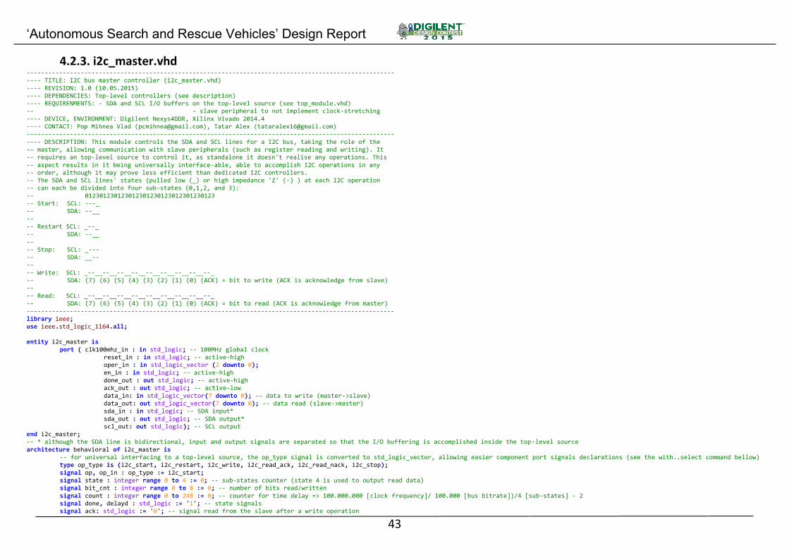
4.2.3. i2c_master.vhd ------------------------------------------------------------------------------------------------------ ---- TITLE: I2C bus master controller (i2c_master.vhd) ---- REVISION: 1.0 (10.05.2015) ---- DEPENDENCIES: Top-level controllers (see description) ---- REQUIRENMENTS: - SDA and SCL I/O buffers on the top-level source (see top_module.vhd) -- - slave peripheral to not implement clock-stretching ---- DEVICE, ENVIRONMENT: Digilent Nexys4DDR, Xilinx Vivado 2014.4 ---- CONTACT: Pop Mihnea Vlad ([email protected]), Tatar Alex ([email protected]) ------------------------------------------------------------------------------------------------------ ---- DESCRIPTION: This module controls the SDA and SCL lines for a I2C bus, taking the role of the -- master, allowing communication with slave peripherals (such as register reading and writing). It -- requires an top-level source to control it, as standalone it doesn't realise any operations. This -- aspect results in it being universally interface-able, able to accomplish I2C operations in any -- order, although it may prove less efficient than dedicated I2C controllers. -- The SDA and SCL lines' states (pulled low (_) or high impedance 'Z' (-) ) at each I2C operation -- can each be divided into four sub-states (0,1,2, and 3): -- 012301230123012301230123012301230123 -- Start: SCL: ---_ -- SDA: --__ -- -- Restart SCL: _--_ -- SDA: --__ -- -- Stop: SCL: _--- -- SDA: __-- -- -- Write: SCL: _--__--__--__--__--__--__--__--__--_ -- SDA: (7) (6) (5) (4) (3) (2) (1) (0) (ACK) = bit to write (ACK is acknowledge from slave) -- -- Read: SCL: _--__--__--__--__--__--__--__--__--_ -- SDA: (7) (6) (5) (4) (3) (2) (1) (0) (ACK) = bit to read (ACK is acknowledge from master) ------------------------------------------------------------------------------------------------------ library ieee; use ieee.std_logic_1164.all; entity i2c_master is port ( clk100mhz_in : in std_logic; -- 100MHz global clock reset_in : in std_logic; -- active-high oper_in : in std_logic_vector (2 downto 0); en_in : in std_logic; -- active-high done_out : out std_logic; -- active-high ack_out : out std_logic; -- active-low data_in: in std_logic_vector(7 downto 0); -- data to write (master->slave) data_out: out std_logic_vector(7 downto 0); -- data read (slave->master) sda_in : in std_logic; -- SDA input* sda_out : out std_logic; -- SDA output* scl_out: out std_logic); -- SCL output end i2c_master; -- * although the SDA line is bidirectional, input and output signals are separated so that the I/O buffering is accomplished inside the top-level source architecture behavioral of i2c_master is -- for universal interfacing to a top-level source, the op_type signal is converted to std_logic_vector, allowing easier component port signals declarations (see the with..select command bellow) type op_type is (i2c_start, i2c_restart, i2c_write, i2c_read_ack, i2c_read_nack, i2c_stop); signal op, op_in : op_type := i2c_start; signal state : integer range 0 to 4 := 0; -- sub-states counter (state 4 is used to output read data) signal bit_cnt : integer range 0 to 8 := 0; -- number of bits read/written signal count : integer range 0 to 248 := 0; -- counter for time delay => 100.000.000 [clock frequency]/ 100.000 [bus bitrate])/4 [sub-states] - 2 signal done, delayd : std_logic := '1'; -- state signals signal ack: std_logic := '0'; -- signal read from the slave after a write operation

‘Autonomous Search and Rescue Vehicles’ Design Report
44
signal datain : std_logic_vector(8 downto 0) := (others => '0'); -- data read including the acknowledge bit signal dataout : std_logic_vector(7 downto 0) := (others => '0'); -- data to write begin with oper_in select op_in <= i2c_start when "001", i2c_restart when "011", i2c_write when "010", i2c_read_ack when "110", i2c_read_nack when "100", i2c_stop when others; -- converts std_logic_vector to op_type done_out <= done; -- connects the internal 'done' signal to the module output 'done_out' i2c_ctrl: process(clk100mhz_in) begin if (rising_edge(clk100mhz_in)) then -- resets all signals used by this process if (reset_in='1') then bit_cnt <= 0; count <= 0; done <= '1'; state <= 0; ack <= '0'; delayd <= '1'; op <= i2c_start; datain <= (others => '0'); dataout <= (others => '0'); data_out<= (others => '0'); ack_out<= '0'; scl_out<= '1'; sda_out<= '1'; else if (done='1') then -- wait for each sub-state to finish if (en_in='1') then -- wait for the start signal done <= '0'; state <= 0; op <= op_in; dataout <= data_in; bit_cnt<= 0; end if; elsif (delayd = '0') then -- delay is required only for sub-state 0,1,2,3, not 4 if (count=248) then -- time delay, to allow correct bitrate count <= 0; delayd <= '1'; else count <= count + 1; end if; else case state is -- see description for SDA and SCL states at each sub-state when 0 => state <= 1; delayd <= '0'; case op is when i2c_start => scl_out<= '1'; --when '0' the line is pulled low by the master, when '1' the line is in high impedance ('Z') sda_out<= '1'; when i2c_restart => scl_out<= '0'; sda_out<= '1'; when i2c_stop => scl_out<= '0'; sda_out<= '0'; when i2c_write => scl_out<= '0'; if (bit_cnt=8) then sda_out<= '1'; -- allows the reading of slave's acknowledge bit
‘Autonomous Search and Rescue Vehicles’ Design Report
45
else sda_out<= dataout(7);-- serially output the data required end if; when i2c_read_ack => scl_out<= '0'; if (bit_cnt=8) then sda_out<= '0'; -- send the ACK bit (pull SDA low) else sda_out<= '1'; -- allow the reading slave's data bits end if; when i2c_read_nack => scl_out<= '0'; sda_out<= '1'; -- allow the reading slave's data bits, and also send the NACK bit (keep SDA in 'Z') end case; dataout <= dataout(6 downto 0) & '0'; -- bit-shift to the next bit when 1 => state <= 2; delayd <= '0'; case op is when i2c_start => scl_out<= '1'; sda_out<= '1'; when i2c_restart => scl_out<= '1'; sda_out<= '1'; when i2c_stop => scl_out<= '1'; sda_out<= '0'; when i2c_write => scl_out<= '1'; when i2c_read_ack => scl_out<= '1'; when i2c_read_nack => scl_out<= '1'; end case; when 2 => state <= 3; delayd <= '0'; case op is when i2c_start => scl_out<= '1'; sda_out<= '0'; when i2c_restart => scl_out<= '1'; sda_out<= '0'; when i2c_stop => scl_out<= '1'; sda_out<= '1'; when i2c_write => scl_out<= '1'; if (bit_cnt=8) then ack <= sda_in; -- read of slave's acknowledge bit end if; when i2c_read_ack => scl_out<= '1'; datain <= datain(7 downto 0) & sda_in; when i2c_read_nack => scl_out<= '1'; datain <= datain(7 downto 0) & sda_in; end case;

‘Autonomous Search and Rescue Vehicles’ Design Report
46
when 3 => delayd <= '0'; case op is when i2c_start => scl_out<= '0'; sda_out<= '0'; when i2c_restart => scl_out<= '0'; sda_out<= '0'; when i2c_stop => scl_out<= '1'; sda_out<= '1'; when i2c_write => scl_out<= '0'; when i2c_read_ack => scl_out<= '0'; when i2c_read_nack => scl_out<= '0'; end case; case op is -- depending on the operation, certain additional steps are required when i2c_start | i2c_restart | i2c_stop => state <= 4; when i2c_write | i2c_read_ack | i2c_read_nack => -- if all 8 bits ave been read/written, go to next step, else go to next bit if (bit_cnt=8) then state <= 4; else bit_cnt <= bit_cnt + 1; state <= 0; end if; end case; when 4 => done <= '1'; if (op=i2c_read_ack or op=i2c_read_nack) then -- output the 8-bit read data data_out <= datain(8 downto 1); end if; if (op=i2c_write) then -- output the slave acknowledge bit ack_out <= ack; end if; end case; end if; end if; end if; end process i2c_ctrl; end behavioral;
4.2.4. ir_thermo.vhd ------------------------------------------------------------------------------------------------------------------------------------------------------------------------------ ---- TITLE: Contactless Infrared Thermometer controller (ir_thermo.vhd) ---- REVISION: 1.0 (10.05.2015) ---- DEPENDENCIES: None ---- REQUIRENMENTS: None ---- DEVICE, ENVIRONMENT: Digilent Nexys4DDR, Xilinx Vivado 2014.4 ---- CONTACT: Pop Mihnea Vlad ([email protected]), Tatar Alex ([email protected]) ------------------------------------------------------------------------------------------------------------------------------------------------------------------------------ ---- DESCRIPTION: This module controls a household-usage infrared ear and ambiental thermometer. As there are no available documentations on-line (due to the lack of any -- identifiable on-board chip marking, the following informations was obtained manually: through the on-board header the device seems to output a SPI-like data -- (V=VCC,D=data,C=clock,G=ground,A = 'Action'/Slave Select ("Measure" button),M=power ("Menu" button). To obtain a temperature measurement, the following steps are necessary:
‘Autonomous Search and Rescue Vehicles’ Design Report
47
-- - pull "Menu" low, the device goes from sleep mode to ear temperature measuring mode, -- - pull "Menu" and "Measure" low for a second, the device goes to room temperature measuring mode, -- - pull "Measure" low at a rate of 5Hz , ambient temperature is continuously measured and serially outputted through the 'data' pin on the 'clock' pin falling-edge, -- - each measurement cycle outputs a 40-bit data string, composed of the following 8-bit words: [0x5B t1t2 t3t4 checksum 0x0D], where the 4-bit words t1, t2, t3 and t4, -- when converted from hex to char results in t1=tens of degrees, t2=degrees, t3=1/10 degrees, t4=1/100 degrees Celsius, checksum is the binary sum of the first 24 bits, -- while 0x5B and 0x0D represents the start and ending markers for the data stream. -- - the 4 4-bit temperature data is outputted from this module only when the checksum is correct ------------------------------------------------------------------------------------------------------------------------------------------------------------------------------ library ieee; use ieee.std_logic_1164.all; use ieee.numeric_std.all; -- used for the 'std_logic_vector' and 'to_unsigned' type conversion entity ir_thermo is port ( clk100mhz_in : in std_logic; -- 100MHz global clock reset_in : in std_logic; -- active-high irtmp_miso_in : in std_logic; -- active-high irtmp_clk_in : in std_logic; -- active-high irtmp_ss_out : out std_logic; -- active-low irtmp_pwr_out : out std_logic; -- active-low data_out : out std_logic_vector (15 downto 0); -- see description done_out : out std_logic); -- active-high end ir_thermo; architecture behavioral of ir_thermo is -- see description for signals used signal clk5hz, power_out : std_logic := '1'; signal clock_in : std_logic; begin irtmp_ss_out <= clk5hz; irtmp_pwr_out <= power_out; clock_in <= irtmp_clk_in when (rising_edge(clk100mhz_in)); process (clk100mhz_in) is -- 100MHz to 5Hz, 50% duty cycle, clock divider variable count: integer range 0 to 9999999; -- (100.000.000/5)/2 - 1 variable cycles : integer range 0 to 3; begin if (rising_edge(clk100mhz_in)) then if (reset_in = '1') then -- resets all signals used by this process count := 0; clk5hz <= '1'; power_out <= '1'; cycles := 0; else if (count = 9999999) then clk5hz <= not clk5hz; -- to obtain a 50% duty cycle, the clk5Hz signal is negated at each 10.000.000 cycles (or 10MHz), resulting an 5Hz clock count := 0; if (cycles /= 2) then -- to pulse the "Menu" button - see description power_out <= not power_out; cycles := cycles + 1; end if; else count := count + 1; end if; end if; end if; end process; process (clock_in) is variable count : integer range 0 to 40; variable data : std_logic_vector (0 to 31); begin
‘Autonomous Search and Rescue Vehicles’ Design Report
48
if (falling_edge(clock_in)) then if (reset_in = '1') then count := 0; data := (others => '0'); data_out <= (others => '0'); done_out <= '1'; else if (count = 39) then if (std_logic_vector(unsigned(data(0 to 7)) + unsigned(data(8 to 15)) + unsigned(data(16 to 23))) = data(24 to 31)) then -- checksum check - see description data_out <= data (8 to 23); done_out <= '1'; else data_out <= (others => '0'); end if; count := 0; else done_out <= '0'; if (count < 32) then -- only useful data bits are saved - see description data(count) := irtmp_miso_in; end if; count := count + 1; end if; end if; end if; end process; end behavioral;
4.2.5. LCD.vhd ---------------------------------------------------------------------------------------------------- ---- TITLE: HannStar HSD043I9W1 LCD screen timing generator (LCD.vhd) ---- REVISION: 1.0 (10.05.2015) ---- DEPENDENCIES: None ---- REQUIRENMENTS: None ---- DEVICE, ENVIRONMENT: Digilent Nexys4DDR, Xilinx Vivado 2014.4 ---- CONTACT: Pop Mihnea Vlad ([email protected]), Tatar Alex ([email protected]) ---------------------------------------------------------------------------------------------------- ---- DESCRIPTION: This module generates the required signals by the HSD043I9W1 LCD screen, -- operating it in DCLK/DE mode (instead of H-sync/V-sync mode) ---------------------------------------------------------------------------------------------------- library ieee; use ieee.std_logic_1164.all; use ieee.numeric_std.all; -- used for the 'std_logic_vector' and 'to_unsigned' type conversion entity lcd is port ( clk100mhz_in : in std_logic; -- 100MHz global clock reset_in : in std_logic; -- active-high lcd_de_out : out std_logic; -- active-high lcd_clk_out : out std_logic; -- active-high hor_cnt_out : out std_logic_vector (9 downto 0); --horizontal counter used to sync the top-level module with the LCD timing vert_cnt_out : out std_logic_vector (8 downto 0)); -- vertical counter ^ end lcd; architecture behavioral of lcd is constant h_active : integer := 480; -- horizontal active area (clock cycles) constant v_active : integer := 272; -- vertical active area constant h_max : integer := 544; -- horizontal maximum area

‘Autonomous Search and Rescue Vehicles’ Design Report
49
constant v_max : integer := 307; -- vertical maximum area signal h_counter : integer range 0 to 1023 := 0; -- horizontal current position counters signal v_counter : integer range 0 to 511 := 0; -- vertical current position counters signal clk10mhz : std_logic; -- 10MHz clock required by the LCD screen logic signal active_area : std_logic; -- signals that the LCD screen is currently in it's active area begin active_area <= '1' when (h_counter < h_active and v_counter < v_active) else '0'; -- active area when the horizontal and vertical counters are lesser than the number of active area clock cycles lcd_clk_out <= clk10mhz; lcd_de_out <= active_area; hor_cnt_out <= std_logic_vector(to_unsigned(h_counter, 10)); vert_cnt_out <= std_logic_vector(to_unsigned(v_counter, 9)); clk_div : process (clk100mhz_in) -- 100MHz to 10MHz, 50% duty cycle, clock divider variable count : integer range 0 to 4; -- (100.000.000/10.000.000)/2 - 1 begin if (rising_edge(clk100mhz_in)) then if (reset_in = '1') then -- resets all signals used by this process count := 0; clk10mhz <= '0'; else if (count = 4) then count := 0; clk10mhz <= not clk10mhz; -- to obtain a 50% duty cycle, the clk10MHz signal is negated at each 5 cycles (or 20MHz), resulting an 10MHz clock else count := count + 1; end if; end if; end if; end process clk_div; -- The following processes count (increment) the horizontal and vertical counters at each 10MHz clock rising edge h_count : process (clk10mhz) begin if (rising_edge(clk10mhz)) then if (reset_in = '1') then h_counter <= 0; else if(h_counter = h_max) then h_counter <= 0; else h_counter <= h_counter + 1; end if; end if; end if; end process h_count; v_count: process (clk10mhz) begin if (rising_edge(clk10mhz)) then if(reset_in = '1') then v_counter <= 0; else if(h_counter = h_max) then if(v_counter = v_max) then v_counter <= 0; else v_counter <= v_counter + 1; end if; end if; end if;

‘Autonomous Search and Rescue Vehicles’ Design Report
50
end if; end process v_count; end behavioral;
4.2.6. magnetometer.vhd ---------------------------------------------------------------------------------------------------- ---- TITLE: Honeywell HMC5883L I2C 3-axis magnetometer interfacer (magnetometer.vhd) ---- REVISION: 1.0 (10.05.2015) ---- DEPENDENCIES: I2C Master Controller (i2c_master.vhd) ---- REQUIRENMENTS: - SDA and SCL I/O buffers on the top-level source (see top_module.vhd) -- - DSP48 slice(s) for heading's calculation required arithmetic operations ---- DEVICE, ENVIRONMENT: Digilent Nexys4DDR, Xilinx Vivado 2014.4 ---- CONTACT: Pop Mihnea Vlad ([email protected]), Tatar Alex ([email protected]) ---------------------------------------------------------------------------------------------------- ---- DESCRIPTION: This module allows the reading of HMC5883L's X and Y axis 16-bit magnetic strength -- registers, converting them to a 0-360 degrees heading ---------------------------------------------------------------------------------------------------- library ieee; use ieee.std_logic_1164.all; use ieee.numeric_std.all; -- used for the 'to_integer' type conversion entity magnetometer is port ( clk100mhz_in : in std_logic; -- 100MHz global clock reset_in : in std_logic; -- active-high start_in : in std_logic; -- active-high magn_drdy : in std_logic; -- active-low signal from the HMC5883L Int pin done_out : out std_logic; -- active-high data_out : out std_logic_vector(8 downto 0); -- 0-360 degrees heading magn_sda_in : in std_logic; -- SDA input* magn_sda_out : out std_logic; -- SDA output* magn_scl_out : out std_logic); -- SCL output end magnetometer; -- * although the SDA line is bidirectional, input and output signals are separated so that the I/O buffering is accomplished inside the top-level source architecture behavioral of magnetometer is component i2c_master is -- for the actual I2C SDA and SCL lines control, the i2c_master module is used (see i2c_master.vhd for more info) port ( clk100mhz_in : in std_logic; reset_in : in std_logic; oper_in : in std_logic_vector(2 downto 0); en_in : in std_logic; done_out : out std_logic; ack_out : out std_logic; data_in: in std_logic_vector(7 downto 0); data_out: out std_logic_vector(7 downto 0); sda_in : in std_logic; sda_out : out std_logic; scl_out: out std_logic); end component; -- for universal interfacing to the i2c_master, the op_type signal is converted to std_logic_vector, allowing easier component port signals declarations (see the with..select command bellow) type op_type is (i2c_start, i2c_restart, i2c_write, i2c_read_ack, i2c_read_nack, i2c_stop); signal i2c_op : op_type := i2c_start; signal i2c_oper : std_logic_vector (2 downto 0) := "001"; signal i2c_en, i2c_done, i2c_ack : std_logic; -- status signals inputted/outputted from the i2c_master module signal data_out_buff : std_logic_vector(31 downto 0); -- read 8-bit MSB and 8-bit LSB data for X and Y axis - MSB(X)&LSB(X)&MSB(Y)&MSB(Y) signal i2c_data_in, i2c_data_out : std_logic_vector(7 downto 0); -- I2C interface 8-bit inputted (from slave to master) and outputted (from master to slave) signal initialised : std_logic := '0'; -- to assure correct operation, at startup or after a reset signal, a number of HMC5883L registers are read and verified

‘Autonomous Search and Rescue Vehicles’ Design Report
51
signal done : std_logic := '1'; -- signals that this module has finished reading the registers and data_out is refreshed signal state : integer range 0 to 24 := 0; -- internal state machine counter begin i2c_master_module : i2c_master port map (clk100mhz_in, reset_in, i2c_oper, i2c_en, i2c_done, i2c_ack, i2c_data_out, i2c_data_in, magn_sda_in, magn_sda_out, magn_scl_out); -- component instantiation with i2c_op select i2c_oper <= "001" when i2c_start, "011" when i2c_restart, "010" when i2c_write, "110" when i2c_read_ack, "100" when i2c_read_nack, "000" when i2c_stop; -- converts op_type to std_logic_vector done_out <= done; -- connects the internal 'done' signal to the module output 'done_out' magn_i2c_ctrl: process (clk100mhz_in) variable count : integer range 0 to 9999999; -- counter for time delays (for 100MHz clock, 1.000.000 pulses = 10mSecs) variable error_count : integer range 0 to 10; -- counts the number of I2C acknowledge errors begin if (rising_edge(clk100mhz_in)) then if (reset_in = '1') then -- resets all signals used by this process done <= '1'; i2c_en <= '0'; i2c_op <= i2c_start; i2c_data_out <= (others => '0'); data_out_buff <= (others => '0'); state <= 0; initialised <= '0'; count := 0; error_count:=0; else if (initialised = '0') then -- at startup or after a reset signal, a number of HMC5883L registers are read and verified if (done = '0') then -- if not done, continue the state machine if (i2c_en = '1') then -- the i2c_en signal needs to be a one-shot for each operation i2c_en <= '0'; elsif (i2c_done='1') then -- wait for i2c_master to finish case state is when 0 => -- START operation i2c_op <= i2c_start; state <= 1; when 1 => -- WRITE operation (11110 is the HMC5883L I2C address, LSB bit is the operation requested) i2c_op <= i2c_write; i2c_data_out <= "00111100"; state <= 2; when 2 => -- Targeted register (0x00 - magnetometer sample averaging) if (i2c_ack = '0') then -- continue if the slave acknowledge correctly, else restart i2c_op <= i2c_write; i2c_data_out <= "00000000"; state <= 3; else state <= 24; end if; when 3 => -- Set sample averaging to 8x if (i2c_ack = '0') then i2c_op <= i2c_write; i2c_data_out <= "01110000"; state <= 4; else state <= 24; end if; when 4 => -- Restart operation if (i2c_ack = '0') then i2c_op <= i2c_restart; state <= 5; else

‘Autonomous Search and Rescue Vehicles’ Design Report
52
state <= 24; end if; when 5 => -- Write operation (LSB='1' equals register reading, LSB='0' equals writing) i2c_op <= i2c_write; i2c_data_out <= "00111100"; state <= 6; when 6 => -- Targeted register (0x00 - magnetometer sample averaging) if (i2c_ack = '0') then i2c_op <= i2c_write; i2c_data_out <= "00000000"; state <= 7; else state <= 24; end if; when 7 => -- Restart operation if (i2c_ack = '0') then i2c_op <= i2c_restart; state <= 8; else state <= 24; end if; when 8 => -- Read operation i2c_op <= i2c_write; i2c_data_out <= "00111101"; state <= 9; when 9 => -- Read register if (i2c_ack = '0') then i2c_op <= i2c_read_nack; state <= 10; else state <= 24; end if; when 10 => -- Sample averaging register read data_out_buff(31 downto 24) <= i2c_data_in; state <= 11; when 11 => -- Restart operation i2c_op <= i2c_restart; state <= 12; when 12 => -- Write operation i2c_op <= i2c_write; i2c_data_out <= "00111100"; state <= 13; when 13 => -- Targeted starting register (0xA - magnetometer ID) if (i2c_ack = '0') then i2c_op <= i2c_write; i2c_data_out <= "00001010"; state <= 14; else state <= 24; end if; when 14 => -- Restart operation if (i2c_ack = '0') then i2c_op <= i2c_restart; state <= 15; else state <= 24; end if; when 15 => -- Read operation i2c_op <= i2c_write; i2c_data_out <= "00111101";

‘Autonomous Search and Rescue Vehicles’ Design Report
53
state <= 16; when 16 => -- Magnetometer ID registers read if (i2c_ack = '0') then i2c_op <= i2c_read_ack; state <= 17; else state <= 24; end if; when 17 => -- First ID register read data_out_buff(23 downto 16) <= i2c_data_in; state <= 18; when 18 => i2c_op <= i2c_read_ack; state <= 19; when 19 => -- Second ID register read data_out_buff(15 downto 8) <= i2c_data_in; state <= 20; when 20 => i2c_op <= i2c_read_nack; state <= 21; when 21 => -- Third ID register read data_out_buff(7 downto 0) <= i2c_data_in; state <= 22; when 22 => -- Stop operation i2c_op <= i2c_stop; state <= 23; when 23 => -- check the read registers with the HMC5883L's datasheet values, retry if not correct if (data_out_buff = "01110000010010000011010000110011") then -- the correct values are 0x70 & 0x48 & 0x34 & 0x33 error_count:=0; done <= '1'; initialised <= '1'; end if; state <= 0; when others => -- Acknowledge error (the SDA line was not pulled low) i2c_op <= i2c_stop; state <= 0; if (error_count = 10) then -- try 10 times, then give up error_count:=0; done <= '1'; else error_count := error_count + 1; end if; end case; if (state /= 10 and state /= 17 and state /= 19 and state /= 21 and state /= 23) then -- set the i2c_en high only when a I2C operation is required i2c_en <= '1'; end if; end if; else done <= '0'; end if; else -- registers have been verified, thus it's safe to communicate with the HMC5883L if (start_in = '1' and done = '1') then -- wait for the start signal done <= '0'; end if; if (done = '0') then if (i2c_en = '1') then i2c_en <= '0'; elsif (i2c_done='1') then case state is

‘Autonomous Search and Rescue Vehicles’ Design Report
54
when 0 => -- START operation i2c_op <= i2c_start; state <= 1; when 1 => -- WRITE operation i2c_op <= i2c_write; i2c_data_out <= "00111100"; -- mode state <= 2; when 2 => -- Targeted register (0x02 - magnetometer measurement mode) if (i2c_ack = '0') then i2c_op <= i2c_write; i2c_data_out <= "00000010"; state <= 3; else state <= 23; end if; when 3 => -- Set measurement mode to single mode if (i2c_ack = '0') then i2c_op <= i2c_write; i2c_data_out <= "00000001"; state <= 4; else state <= 23; end if; when 4 => -- Stop operation if (i2c_ack = '0') then i2c_op <= i2c_stop; state <= 5; else state <= 23; end if; when 5 => -- Wait for 10mSecs, or when HMC5883L Int pin is low (meaning measurement is complete) if (count = 1000000 or magn_drdy = '0') then state <= 6; count := 0; else count := count + 1; end if; when 6 => -- Start operation i2c_op <= i2c_start; state <= 7; when 7 => -- Write operation i2c_op <= i2c_write; i2c_data_out <= "00111100"; state <= 8; when 8 => -- Targeted register (0x03 - magnetometer X axis MSB register) if (i2c_ack = '0') then i2c_op <= i2c_write; i2c_data_out <= "00000011"; state <= 9; else state <= 23; end if; when 9 => -- Restart operation if (i2c_ack = '0') then i2c_op <= i2c_restart; state <= 10; else state <= 23; end if; when 10 => -- Read operation

‘Autonomous Search and Rescue Vehicles’ Design Report
55
i2c_op <= i2c_write; i2c_data_out <= "00111101"; state <= 11; when 11 => -- Read register if (i2c_ack = '0') then i2c_op <= i2c_read_ack; state <= 12; else state <= 23; end if; when 12 => -- X axis MSB register read data_out_buff(31 downto 24) <= i2c_data_in; state <= 13; when 13 => i2c_op <= i2c_read_ack; state <= 14; when 14 => -- X axis LSB register read data_out_buff(23 downto 16) <= i2c_data_in; state <= 15; when 15 => -- Z axis MSB register read (this axis is not required, so it is read, but saving it's values is skipped) i2c_op <= i2c_read_ack; state <= 16; when 16 => -- Z axis LSB register read i2c_op <= i2c_read_ack; state <= 17; when 17 => i2c_op <= i2c_read_ack; state <= 18; when 18 => -- Y axis MSB register read data_out_buff(15 downto 8) <= i2c_data_in; state <= 19; when 19 => i2c_op <= i2c_read_nack; state <= 20; when 20 => -- Y axis LSB register read data_out_buff(7 downto 0) <= i2c_data_in; state <= 21; when 21 => -- Stop operation i2c_op <= i2c_stop; state <= 22; when 22 => -- Register reading done error_count:=0; done <= '1'; state <= 0; when others => -- Acknowledge error (the SDA line was not pulled low) i2c_op <= i2c_stop; state <= 0; if (error_count = 10) then error_count:=0; done <= '1'; else error_count := error_count + 1; end if; end case; if (state /= 5 and state /= 12 and state /= 14 and state /= 18 and state /= 20 and state /= 22) then i2c_en <= '1'; end if; end if; end if; end if;

‘Autonomous Search and Rescue Vehicles’ Design Report
56
end if; end if; end process magn_i2c_ctrl; -- To obtain the result value of an arctan2(x,y) (also known as arctan(y/x)) operation required to calculate a heading (0~360 degrees) from the magnetometer's X and Y axis readings, -- avoiding other higher accuracy but also more complex algorithms (rotating-vector CORDIC, for example), the following integer (not fixed-point representation) approximation was implemented, -- which yields a average error of a 2 degress (value in specs with HMC5883L's heading accuracy declared in it's datasheet) atan2_approx: process (done) variable x, y : integer range 0 to 2047; -- absolute X axis magnetometer reading value in integer variable arctan2 : integer range 0 to 65535; -- absolute Y axis magnetometer reading value in integer variable flipped : std_logic; -- begin if (rising_edge(done)) then -- this process is triggered when the main process (magn_i2c_ctrl) is done (meaning all required registers have been read) if (reset_in = '1') then data_out <= (others => '0'); x:=0; y:=0; flipped:='0'; arctan2:=0; else -- if HMC5883L's measurements have over- or under-flown, the value stored will be -4096, so a quick check is required to prevent erroneous calculations (checks for null values are also used) if (data_out_buff(31 downto 27)/="1110" and data_out_buff(15 downto 11) /= "1110" and data_out_buff(26 downto 16)/="00000000000" and data_out_buff(10 downto 0)/="00000000000") then -- the registers are in 13-bit two's complement format, with the sign on the MSB if (data_out_buff(27)='1') then -- X negative x:=to_integer(unsigned(not data_out_buff(26 downto 16))); -- the register value is negative, thus negating it is necessary else x:=to_integer(unsigned(data_out_buff(26 downto 16))); -- the register value is positive end if; if (data_out_buff(11)='1') then -- Y negative y:=to_integer(unsigned(not data_out_buff(10 downto 0))); else y:=to_integer(unsigned(data_out_buff(10 downto 0))); end if; -- the arctan2() approximation starts here, and works with absolute X and Y readings values up to a maximum of 2.184 (if arctan2 result is unsigned 16-bit) if (x<y) then arctan2:=x; x:=y; y:=arctan2; flipped:='1'; -- 'flip' the X and Y values inbetween, so that X is the higher one else flipped:='0'; end if; arctan2:=30*x; arctan2:=arctan2/y; if (arctan2=0) then arctan2:=90; elsif (arctan2 > 81) then arctan2:=1720/arctan2; else arctan2:=arctan2+8; arctan2:=1720/arctan2; end if; if (flipped='1') then arctan2:=90-arctan2; end if; -- depending on the sign for the X and Y reading, the arctan2 result has to be 'rotated' to the correct quadrant if (data_out_buff(27)='1') then if (data_out_buff(11)='1') then
‘Autonomous Search and Rescue Vehicles’ Design Report
57
arctan2:=180+arctan2; else arctan2:=180-arctan2; end if; else if (data_out_buff(11)='1') then arctan2:=360-arctan2; end if; end if; data_out<=std_logic_vector(to_unsigned(arctan2,9)); -- output the integer value converted in STD_LOGIC_VECTOR, for easier interface to other modules else data_out <= (others => '1'); -- the X and Y reading are invalid, so output 511 (so that the top-level module will known the data is erroneous) end if; end if; end if; end process atan2_approx; end behavioral;
4.2.7. motor_driver.vhd ---------------------------------------------------------------------------------------------------- ---- TITLE: Dual motors controller (motors_driver.vhd) ---- REVISION: 1.0 (10.05.2015) ---- DEPENDENCIES: magnetometer.vhd ---- REQUIRENMENTS: None ---- DEVICE, ENVIRONMENT: Digilent Nexys4DDR, Xilinx Vivado 2014.4 ---- CONTACT: Pop Mihnea Vlad ([email protected]), Tatar Alex ([email protected]) ---------------------------------------------------------------------------------------------------- ---- DESCRIPTION: This module controls two motors (via an L298 dual full-bridge), receiving feedback -- from an rotary encoder on each wheel axe. It also uses the 0~360 degrees heading outputted from the -- magnetometer.vhd module, further improving the accuracy of the turn angle and to keep the platform -- straight during forward/backward movements. The rotary encoders are 24-steps/revolution, with their -- common pin connected to ground and each of their two signal pulled high with a resistor to VCC. ---------------------------------------------------------------------------------------------------- library ieee; use ieee.std_logic_1164.all; use ieee.numeric_std.all; -- used for the 'to_integer' type conversion entity motors_driver is port ( clk100mhz_in : in std_logic; -- 100MHz global clock reset_in : in std_logic; -- active-high start_in : in std_logic_vector(1 downto 0); -- '10'=start without magnetometer, '11'=start with magnetometer dir_in : in std_logic_vector (2 downto 0); -- direction and servo positions - see process bellow for actual values ml_fb_in : in std_logic_vector (1 downto 0); -- left motor feedback*, active low mr_fb_in : in std_logic_vector (1 downto 0); -- right motor feedback*, active low ml_in_out : out std_logic_vector (1 downto 0); -- L298 input signals for left motor, active high mr_in_out : out std_logic_vector (1 downto 0); -- L298 input signals for right motor, active high ml_en_out : out std_logic; -- L298 enable signal for left motor, active high mr_en_out : out std_logic; -- L298 enable signal for right motor, active high done_out : out std_logic; -- active high magn_data_in : in std_logic_vector (8 downto 0); -- heading from magnetometer.vhd magn_done_in : in std_logic; -- done signal from magnetometer.vhd magn_start_out : out std_logic); -- start signal to magnetometer.vhd end motors_driver; -- *fb(1) is first high and fb(0) is last high when the platform is moving forward architecture behavioral of motors_driver is signal ml_fb_s0, ml_fb_s1, ml_fb_s0_prev, mr_fb_s0, mr_fb_s1, mr_fb_s0_prev : std_logic := '0'; -- internal signal obtained after filtering the rotary encoders inputs

‘Autonomous Search and Rescue Vehicles’ Design Report
58
signal done : std_logic := '1'; -- signals that the motors have finished moving for all the required steps signal magn_start1, magn_start2, magn_started1, magn_started2, min_max_done, magn_enable : std_logic := '0'; -- internal state signals* signal data_out : std_logic_vector (4 downto 0) := (others => '0'); -- data buffer for the L298 enable and input signals signal max_heading, min_heading : integer range 0 to 511 := 0; -- heading limits -- *to control the magnetometer.vhd in both the processes (to start it), each process has it's own signals, that are OR-ed begin magn_start_out <= magn_start1 when (min_max_done='0') else magn_start2; -- allow control of magnetometer.vhd from both of the processes done_out <= done; -- connects the internal 'done' signal to the module output 'done_out' ml_en_out <= data_out(4); -- connects the internal buffer to the actual L298 pins mr_en_out <= data_out(4); -- ^ ml_in_out <= data_out(3 downto 2); -- ^ mr_in_out <= data_out(1 downto 0); -- ^ feedback_filter : process (clk100mhz_in) -- filters the feedback inputs for both rotary encoders begin if (rising_edge(clk100mhz_in)) then case (ml_fb_in) is -- left motor feedback when "00" => ml_fb_s0 <= '0'; -- the internal signals are changed using this method, to remove bouncing when "01" => ml_fb_s1 <= '0'; when "10" => ml_fb_s1 <= '1'; when "11" => ml_fb_s0 <= '1'; end case; case (mr_fb_in) is -- right motor feedback when "00" => mr_fb_s0 <= '0'; when "01" => mr_fb_s1 <= '0'; when "10" => mr_fb_s1 <= '1'; when "11" => mr_fb_s0 <= '1'; end case; end if; end process feedback_filter; process (clk100mhz_in) -- calculates the minimum and maximum heading limits, according to the direction requested variable heading, min, max : integer range 0 to 511; -- internal buffers for the limits values begin if (rising_edge(clk100mhz_in)) then if (reset_in = '1') then heading := 0; min := 0; max := 0; min_heading <= 0; max_heading <= 0; magn_start1 <= '0'; magn_started1 <= '0'; min_max_done <= '0'; magn_enable <= '0'; else if (start_in(1)='1' and done = '1') then -- if done, wait for the start signal if (start_in(0)='1') then -- if the LSB is '0', don't use the magnetometer min_max_done <= '0'; -- the min/max values are to be calculated magn_enable <= '1'; else min_max_done <= '1';

‘Autonomous Search and Rescue Vehicles’ Design Report
59
magn_enable <= '0'; end if; end if; if (min_max_done = '0') then if (magn_started1 = '0') then magn_start1 <= '1'; -- get the heading from magnetometer.vhd, by one-shop pulsing the enable signal magn_started1 <= '1'; else magn_start1 <= '0'; if (magn_done_in = '1') then if (magn_data_in /= "111111111") then -- if data valid heading := to_integer(unsigned(magn_data_in)); -- because the heading value is rotating (0 to 360, back to 0, then again 0 to 360, and so on), compensation is required case (dir_in) is when "101"|"010" => -- if going forward or backwards, the headings limits are +5/-5 degrees from the current heading max:=heading + 5; if (heading<5) then -- if the current heading is close to 0, compensate it min:=355+heading; else min:=heading-5; end if; when "100" => -- if 90 degrees to left, the headings limits are +0/-90 degrees from the current heading max:=heading; if (heading<90) then -- if the current heading is close to 0, compensate min min:=270+heading; else min:=heading-90; end if; when "001" => -- if 90 degrees to right, the headings limits are +90/-0 degrees from the current heading max:=heading + 90; min:=heading; when "111" => -- -- if 180 degrees to left, the headings limits are +180/-0 degrees from the current heading max:=heading + 180; min:=heading; when others => max := 0; min := 0; end case; if (max>359) then -- if the max heading is close to 360, compensate it max:=max-360; else end if; min_heading<=min; max_heading<=max; min_max_done <= '1'; -- done calculating/compensating min and max heading values end if; magn_started1 <= '0'; end if; end if; end if; end if; end if; end process; step_control : process (clk100mhz_in) variable ml_fb_done, mr_fb_done, heading_done : std_logic; -- internal signals that signify the completion of the required movement variable ml_fb_count, mr_fb_count : integer range 0 to 15; -- internal feedback steps counters variable heading : integer range 0 to 511; -- current heading variable max_count : integer range 0 to 15; -- maximum number of steps required begin

‘Autonomous Search and Rescue Vehicles’ Design Report
60
if (rising_edge(clk100mhz_in)) then if (reset_in = '1') then data_out <= (others => '0'); done <= '1'; ml_fb_count := 0; mr_fb_count := 0; ml_fb_done := '0'; mr_fb_done := '0'; heading_done := '0'; ml_fb_s0_prev <= '0'; mr_fb_s0_prev <= '0'; magn_started2 <= '0'; magn_start2 <= '0'; heading := 0; max_count := 0; else if (start_in(1) = '1' and done = '1') then -- if done, wait for start signal case (dir_in) is -- set the L298 input signals for the respective movement when "101" => -- forwards data_out(3 downto 0) <= "1010"; -- left&right motor done <= '0'; max_count := 15; -- number of steps required when "010" => -- backwards data_out(3 downto 0) <= "0101"; done <= '0'; max_count := 15; when "100" => -- 90 degrees to left done <= '0'; max_count := 5; data_out(3 downto 0) <= "1001"; when "001" => -- 90 degrees to right data_out(3 downto 0) <= "0110"; done <= '0'; max_count := 5; when "111" => -- 180 degrees to right data_out(3 downto 0) <= "0110"; done <= '0'; max_count := 10; when others => -- stop done <= '1'; max_count := 0; data_out <= "00000"; end case; heading_done := '0'; end if; if (done = '0' and min_max_done='1') then -- if not done, wait for min/max calculations if (magn_enable = '1') then -- pulse the magnetometer.vhd enable pin if (magn_started2 = '0') then magn_start2 <= '1'; magn_started2 <= '1'; else magn_start2 <= '0'; if (magn_done_in = '1') then if (magn_data_in /= "111111111") then heading := to_integer(unsigned(magn_data_in)); case (dir_in) is when "001"|"111" => -- 90 or 180 degrees right if (max_heading<min_heading) then -- if max value compensated if (heading>=max_heading and heading<min_heading) then heading_done := '1'; -- rotated 90/180 degrees
‘Autonomous Search and Rescue Vehicles’ Design Report
61
end if; else if (heading>=max_heading) then heading_done := '1'; end if; end if; when "100" => -- 90 degrees left if (max_heading<min_heading) then -- if min value compensated if (heading<=min_heading and heading>max_heading) then heading_done := '1'; -- rotated 90 degrees end if; else if (heading<=min_heading) then heading_done := '1'; end if; end if; when "101"|"010" => -- forwards if (dir_in="101") then data_out(3 downto 0)<="1010"; else data_out(3 downto 0)<="0101"; end if; if (max_heading<min_heading) then -- if max value compensated if (heading>=max_heading and heading<min_heading) then -- if drifting to the right data_out(3 downto 0)<="1001"; -- turn to the opposite direction end if; else if (heading>=max_heading) then data_out(3 downto 0)<="1001"; end if; end if; if (max_heading<min_heading) then -- if min value compensated if (heading<=min_heading and heading>max_heading) then -- if drifting to the left data_out(3 downto 0)<="0110"; end if; else if (heading<=min_heading) then data_out(3 downto 0)<="0110"; end if; end if; when others => end case; end if; magn_started2 <= '0'; end if; end if; end if; if (ml_fb_count < max_count) then -- count the number of steps done by the left motor ml_fb_s0_prev <= ml_fb_s0; if (ml_fb_s0 = '1' and ml_fb_s0_prev = '0') then -- if this step was not already counted ml_fb_count := ml_fb_count + 1; end if; else ml_fb_done := '1'; end if; if (mr_fb_count < max_count) then -- count the number of steps done by the right motor mr_fb_s0_prev <= mr_fb_s0; if (mr_fb_s0 = '1' and mr_fb_s0_prev = '0') then mr_fb_count := mr_fb_count + 1;

‘Autonomous Search and Rescue Vehicles’ Design Report
62
end if; else mr_fb_done := '1'; end if; if ((ml_fb_done = '1' and mr_fb_done = '1') or heading_done='1') then -- if both counters are at the required number OR 180/90 degrees rotated done <= '1'; heading_done := '0'; data_out <= "00000"; -- set all L298 inputs to low ml_fb_count := 0; mr_fb_count := 0; ml_fb_done := '0'; mr_fb_done := '0'; else data_out(4) <= '1'; -- set both left and right L298 enables to high end if; end if; end if; end if; end process step_control; end behavioral;
4.2.8. rf_motor_driver.vhd ---------------------------------------------------------------------------------------------------- ---- TITLE: Radio-transmitter motors and servos controller (rf_motor_driver.vhd) ---- REVISION: 1.0 (10.05.2015) ---- DEPENDENCIES: None ---- REQUIRENMENTS: None ---- DEVICE, ENVIRONMENT: Digilent Nexys4DDR, Xilinx Vivado 2014.4 ---- CONTACT: Pop Mihnea Vlad ([email protected]), Tatar Alex ([email protected]) ---------------------------------------------------------------------------------------------------- ---- DESCRIPTION: This module controls two motors (via a ESC-driven L298 dual full-bridge) and -- two servos wirelessly, using a pair of unbranded 2.4GHz one-way transmitter/receiver devices -- (which were removed from a radio-controlled toy car). The transmitter accepts an asynchronous -- serial signal composed of the following pulses (where each high pulse represents one of the four -- output channels from the receiver): -- _ _____ _____ _____ _____ _ -- | | ch1 | | ch2 | | ch3 | | ch4 | | -- |_| |_| |_| |_| |_| -- Each low pulse is 400uSecs, while each high pulse is 400uSecs shorter that the period outputted -- by the receiver. The entire pulse train inputted at the transmitter and each individual signal -- outputted by the receiver is repeated at a rate of 50Hz (50mSecs), allowing the control of any -- standard, analogue servos and ESCs (electronic speed controllers). -- For the present project, on the first two channels an ESC is connected, while on the other two -- 1.1~1.9mSecs servo are used. The ESC uses the first channel for the throttle (1.1mSecs = full -- backwards, 1.5mSecs = stop, and 1.9mSecs = full forwards), and the second channel for direction -- (1.1mSecs = full left, 1.5mSecs = centre, and 1.9mSecs = full right). Also, when the throttle is -- at 1.5mSecs, the motors rotate in opposite directions when the second channel is not 1.5mSecs -- (allowing the target mobile platform to rotate on the spot), while at other values, the platform -- turns while going forward/backward. The Servos are mirror mounted, thus the pulse widths are -- also mirrored at 1.5mSecs (1.5mSecs is equivalent to the centre position). ---------------------------------------------------------------------------------------------------- library ieee; use ieee.std_logic_1164.all; entity rf_motor_driver is port ( clk100mhz_in : in std_logic; -- 100MHz global clock

‘Autonomous Search and Rescue Vehicles’ Design Report
63
reset_in : in std_logic; -- active-high dir_in : in std_logic_vector (4 downto 0); -- direction and servo positions - see process bellow for actual values start_in : in std_logic; -- active-high done_out : out std_logic; -- active-high rf_data_out : out std_logic); -- signal outputted to the transmitter end rf_motor_driver; architecture behavioral of rf_motor_driver is -- to obtain the 20mSecs pulse train, a 200-bit vector is used, where each bit represents the binary state -- at the output, vector which is serially sifted at a rate of 10kHz, thus each state will have a period of 100uSecs signal data_out : std_logic_vector (199 downto 0) := (others => '0'); signal clk10khz : std_logic; -- clock used to serially shift the vector above signal done : std_logic := '0'; -- signals that the motors have finished moving for the set amount of time signal bit_count : integer range 0 to 199 := 199; -- counter to select each bit in succession begin done_out <= done; -- connects the internal 'done' signal to the module output 'done_out' clk_div : process (clk100mhz_in) -- 100MHz to 1MHz, 50% duty cycle, clock divider variable count : integer range 0 to 4999; -- (100.000.000/10.000)/2 - 1 begin if (rising_edge(clk100mhz_in)) then if (reset_in = '1') then -- resets all signals used by this process clk10khz <= '0'; count := 0; else if (count = 4999) then clk10khz <= not clk10khz; -- to obtain a 50% duty cycle, the clk10khz signal is negated at each 50000 cycles (or 20kHz), resulting an 10kHz clock count := 0; else count := count + 1; end if; end if; end if; end process clk_div; pulse_gen : process (clk100mhz_in) variable data_out_buff : std_logic_vector (199 downto 0); -- buffer for the 200-bit output vector variable counter : integer range 0 to 29_000_000 := 29_000_000; -- counter for the time delay variable index : integer range 0 to 195; -- overall index variable index1, index2 : integer range 7 to 16 := 11; -- index(length) for the first and second channel variable index3 : integer range 10 to 14 := 11; -- index for the third channel variable index4 : integer range 8 to 12 := 11; -- index for the fourth channel variable step : integer range 0 to 3 := 0; -- internal state machine counter begin if (rising_edge(clk100mhz_in)) then if (reset_in = '1') then data_out_buff := (others => '0'); data_out <= (others => '0'); done <= '0'; step := 0; index1 := 11; index2 := 11; index3 := 11; index4 := 11; index := 195; counter := 0; elsif (start_in = '1' and done = '1') then -- if done, wait for the start signal done <= '0'; elsif (done = '0') then -- if not done, continue the state machine case (step) is

‘Autonomous Search and Rescue Vehicles’ Design Report
64
when 0 => case (dir_in(4 downto 2)) is -- the first (MSB) three bits decide the direction when "100" => -- rotate left index1 := 7; index2 := 11; counter := 19_000_000; -- rotation requires (100.000.000/19.000.000=) 190mSecs to complete when "001" => -- rotate right index1 := 15; index2 := 11; counter := 19_000_000; when "101" => -- go forwards index1 := 11; index2 := 15; counter := 29_000_000; -- going forward/backward requires 290mSecs to complete when "010" => -- go backwards index1 := 11; index2 := 7; counter := 29000000; when others => -- stop index1 := 11; index2 := 11; end case; case (dir_in(1 downto 0)) is -- the last (LSB) two bits decide the servos position when "01" => -- downwards index3 := 10; index4 := 12; when "10" => -- upwards index3 := 14; index4 := 8; when others => -- centred index3 := 11; index4 := 11; end case; step := 1; when 1 => -- generate the signal, using the four index values set at step 0 data_out_buff := (others => '0'); index := 195; data_out_buff (index downto 0) := (others => '1'); index := index - index1; data_out_buff (index downto 0) := (others => '0'); index := index - 4; data_out_buff (index downto 0) := (others => '1'); index := index - index2; data_out_buff (index downto 0) := (others => '0'); index := index - 4; data_out_buff (index downto 0) := (others => '1'); index := index - index3; data_out_buff (index downto 0) := (others => '0'); index := index - 4; data_out_buff (index downto 0) := (others => '1'); index := index - index4; data_out_buff (index downto 0) := (others => '0'); index := index - 4; data_out_buff (index downto 0) := (others => '1'); data_out <= data_out_buff; if (counter /= 0) then step := 2; -- after the pulse train is sent, wait for the amount time required else step := 3; -- the wait period end if;

‘Autonomous Search and Rescue Vehicles’ Design Report
65
when 2 => -- wait for the set amount of time if (counter = 0) then index1 := 11; -- after waiting, set the two channels back to their centre values index2 := 11; -- thus, the platform will stop step := 1; -- redo the pulse train with the new values else counter := counter - 1; end if; when 3 => -- wait for the pulse train to be sent if (bit_count = 0) then done <= '1'; -- sending done step := 0; end if; end case; end if; end if; end process pulse_gen; data_shift : process (clk10khz) -- serially shift the state vector indefinitely begin if (rising_edge(clk10khz)) then if (reset_in = '1') then bit_count <= 199; else rf_data_out <= data_out(bit_count); if (bit_count = 0) then bit_count <= 199; else bit_count <= bit_count - 1; end if; end if; end if; end process data_shift; end behavioral;
4.2.9. seven_seg_disp.vhd ---------------------------------------------------------------------------------------------------- ---- TITLE: 8-digit, 7-segment LED display controller (seven_seg_disp.vhd) ---- REVISION: 1.0 (10.05.2015) ---- DEPENDENCIES: None ---- REQUIRENMENTS: None ---- DEVICE, ENVIRONMENT: Digilent Nexys4DDR, Xilinx Vivado 2014.4 ---- CONTACT: Pop Mihnea Vlad ([email protected]), Tatar Alex ([email protected]) ---------------------------------------------------------------------------------------------------- ---- DESCRIPTION: This module controls Nexys4DDR's on-board 7-segment display ---------------------------------------------------------------------------------------------------- library ieee; use ieee.std_logic_1164.all; entity seven_seg_disp is port ( clk100mhz_in : in std_logic; -- 100MHz global clock reset_in : in std_logic; -- active-high an_out : out std_logic_vector (7 downto 0); -- active-low (anode) dp_out : out std_logic; -- active-low (dot point) cat_out : out std_logic_vector (6 downto 0); -- active-low (cathode) data_in : in std_logic_vector (31 downto 0)); -- 32-bit data input, incorporating all 8 digits 4-bit-BCD-coded values end seven_seg_disp;

‘Autonomous Search and Rescue Vehicles’ Design Report
66
architecture behavioral of seven_seg_disp is signal clk1khz : std_logic; -- 1kHz clock required to display all segments and digits at a adequate rate begin process (clk100mhz_in) is -- 100MHz to 1kHz, 50% duty cycle, clock divider variable count: integer range 0 to 49999; -- (100.000.000/1.000)/2 - 1 begin if (rising_edge(clk100mhz_in)) then if (reset_in = '1') then -- resets all signals used by this process count := 0; clk1khz <= '0'; else if (count = 49999) then clk1khz <= not clk1khz; -- to obtain a 50% duty cycle, the clk1khz signal is negated at each 50.000 cycles (or 2kHz), resulting an 1kHz clock count := 0; else count := count + 1; end if; end if; end if; end process; process (clk1khz) is variable digit : integer range 0 to 7; variable value : std_logic_vector (3 downto 0); begin if (rising_edge(clk1khz)) then if (reset_in = '1') then digit := 1; cat_out <= "1111111"; an_out <= "11111111"; dp_out <= '1'; value := "0000"; else case (digit) is -- each of the 8 digits and their respective 4-bit data are selected in succession indefinitely when 0 => -- the digits are numbered from 0 to 7, with the hardware equivalence 0 = right-most, 7 = left-most dp_out <= '1'; -- there is a digit point in-between each two digits an_out <= "11111110"; value := data_in(3 downto 0); -- the data-in vector contains all the 8 4-bit data groups, with digit 7 downto 0 when 1 => dp_out <= '1'; an_out <= "11111101"; value := data_in(7 downto 4); when 2 => dp_out <= '0'; an_out <= "11111011"; value := data_in(11 downto 8); when 3 => dp_out <= '1'; an_out <= "11110111"; value := data_in(15 downto 12); when 4 => dp_out <= '0'; an_out <= "11101111"; value := data_in(19 downto 16); when 5 => dp_out <= '1'; an_out <= "11011111"; value := data_in(23 downto 20);

‘Autonomous Search and Rescue Vehicles’ Design Report
67
when 6 => dp_out <= '0'; an_out <= "10111111"; value := data_in(27 downto 24); when 7 => dp_out <= '1'; an_out <= "01111111"; value := data_in(31 downto 28); end case; case (value) is -- depending on the 4-bit-BCD-coded data selected for the present digit, the segments are lit in order to represent all 16 possible characters when "0000" => cat_out <="1000000"; -- 0 when "0001" => cat_out <="1111001"; -- 1 when "0010" => cat_out <="0100100"; -- 2 when "0011" => cat_out <="0110000"; -- 3 when "0100" => cat_out <="0011001"; -- 4 when "0101" => cat_out <="0010010"; -- 5 when "0110" => cat_out <="0000010"; -- 6 when "0111" => cat_out <="1111000"; -- 7 when "1000" => cat_out <="0000000"; -- 8 when "1001" => cat_out <="0010000"; -- 9 when "1010" => cat_out <="0001000"; -- A when "1011" => cat_out <="0100000"; -- B when "1100" => cat_out <="1000110"; -- C when "1101" => cat_out <="1100000"; -- D when "1110" => cat_out <="0000110"; -- E when "1111" => cat_out <="0001110"; -- F end case; if (digit = 7) then -- if at the last digit, start again digit := 0; else digit := digit + 1; end if; end if; end if; end process; end behavioral;
4.2.10. top_module.vhd ---------------------------------------------------------------------------------------------------- ---- TITLE: Top-level source (top_module.vhd) ---- REVISION: 1.0 (10.05.2015) ---- DEPENDENCIES: ambient_thermo.vhd, debouncer.vhd, ir_thermo.vhd, lcd.vhd, magnetometer.vhd, -- motors_driver.vhd, rf_motor_driver.vhd, seven_seg_disp.vhd, ultrasound.vhd ---- REQUIRENMENTS: Hardware constraints file (constraints.xcd) ---- DEVICE, ENVIRONMENT: Digilent Nexys4DDR, Xilinx Vivado 2014.4 ---- CONTACT: Pop Mihnea Vlad ([email protected]), Tatar Alex ([email protected]) ---------------------------------------------------------------------------------------------------- ---- DESCRIPTION: This module represents the top-level source design, incorporating all modules and -- accomplishing the tasks required by our project for the 2015 Digilent Design Contest - 'Autonomous -- Search-and-Rescue Vehicles'. While all the other files are universally usable (if the required -- hardware is available), this source has a very specific application, but it can be used for -- reference regarding the usage of each module. For detailed information regarding mode of -- operations, see code comments present throughout this file, and also attached .pdf documentation. ---------------------------------------------------------------------------------------------------- library ieee; use ieee.std_logic_1164.all; use ieee.numeric_std.all; -- to_integer

‘Autonomous Search and Rescue Vehicles’ Design Report
68
entity top_module is -- for exact hardware pins, see the constraints file (constraints.xdc) port ( clk100mhz : in std_logic; -- 100MHz global clock sw3v3 : in std_logic_vector (13 downto 0); -- Nexys4DDR switches* sw1v8 :in std_logic_vector (1 downto 0); -- Nexys4DDR switches* btn_udlrc : in std_logic_vector (4 downto 0); -- Nexys4DDR buttons (up, down, left, right, centre) cpu_reset : in std_logic; -- Nexys4DDR CPU_reset buttons led : out std_logic_vector (15 downto 0); -- Nexys4DDR LEDs rgb : out std_logic_vector (5 downto 0); -- Nexys4DDR dual RGB LEDs cat : out std_logic_vector (6 downto 0); -- Nexys4DDR 7 segment displays (cathodes) an : out std_logic_vector (7 downto 0); -- Nexys4DDR 7 segment displays (anodes) dp : out std_logic := '1'; -- Nexys4DDR 7 segment displays (dot points) us_trig : out std_logic_vector (2 downto 0); -- HC-SR04 ultrasound modules Trigger signals us_echo : in std_logic_vector (2 downto 0); -- HC-SR04 ultrasound modules Echo signals irtmp_miso : in std_logic; -- Infrared Thermometer data irtmp_clk : in std_logic; -- Infrared Thermometer clock irtmp_ss : out std_logic; -- Infrared Thermometer slave select irtmp_pwr : out std_logic; -- Infrared Thermometer power signal ml_in : out std_logic_vector (1 downto 0); -- Left motor L298 inputs ml_fb : in std_logic_vector (1 downto 0); -- Left motor feedback ml_en : out std_logic; -- Left motor L298 enable mr_in : out std_logic_vector (1 downto 0); -- Right motor L298 inputs mr_fb : in std_logic_vector (1 downto 0); -- Right motor feedback mr_en : out std_logic; -- Right motor feedback rf_data : out std_logic; -- RF transmitter data lcd_de : out std_logic; -- LCD Screen Data enable lcd_clk : out std_logic; -- LCD Screen clock lcd_red : out std_logic_vector (1 downto 0); -- LCD Screen RGB bus (Red) lcd_green : out std_logic_vector (1 downto 0); -- LCD Screen RGB bus (Green) lcd_blue : out std_logic_vector (1 downto 0); -- LCD Screen RGB bus (Blue) magn_drdy : in std_logic; -- Magnetometer DataReady (Int) magn_sda : inout std_logic; -- Magnetometer I2C data (SDA) magn_scl : inout std_logic; -- Magnetometer I2C clock (SCL) tmp_sda : inout std_logic; -- Ambient thermometer I2C data (SDA) tmp_scl : inout std_logic); -- Ambient thermometer I2C clock (SCL) end top_module; -- * to eliminate certain implementation warnings (bus contains signals of different I/O standards), the 1.8V -- level switches are differentiated from the 3.3V ones (workaround applicable for the Nexys4DDR board) architecture behavioral of top_module is -- for detailed information regarding the inputs/outputs of each component, and also mode of function, -- see their respective source file description and/or code comments component ambient_thermo port ( clk100mhz_in : in std_logic; reset_in : in std_logic; start_in : in std_logic; done_out : out std_logic; data_out : out std_logic_vector (15 downto 0); tmp_sda_in : in std_logic; tmp_sda_out : out std_logic; tmp_scl_out : out std_logic); end component; component debouncer port ( clk100mhz_in : in std_logic; sw_in : in std_logic_vector (15 downto 0); btn_in : in std_logic_vector (4 downto 0); cpu_reset_in : in std_logic;

‘Autonomous Search and Rescue Vehicles’ Design Report
69
sw_out : out std_logic_vector (15 downto 0); btn_out : out std_logic_vector (4 downto 0); cpu_reset_out : out std_logic); end component; component ir_thermo port ( clk100mhz_in : in std_logic; reset_in : in std_logic; irtmp_miso_in : in std_logic; irtmp_clk_in : in std_logic; irtmp_ss_out : out std_logic; irtmp_pwr_out : out std_logic; data_out : out std_logic_vector (15 downto 0); done_out : out std_logic); end component; component lcd port ( clk100mhz_in : in std_logic; reset_in : in std_logic; lcd_de_out : out std_logic; lcd_clk_out : out std_logic; hor_cnt_out : out std_logic_vector (9 downto 0); vert_cnt_out : out std_logic_vector (8 downto 0)); end component; component magnetometer port ( clk100mhz_in : in std_logic; reset_in : in std_logic; start_in : in std_logic; magn_drdy : in std_logic; done_out : out std_logic; data_out : out std_logic_vector(8 downto 0); magn_sda_in : in std_logic; magn_sda_out : out std_logic; magn_scl_out : out std_logic); end component; component motors_driver port ( clk100mhz_in : in std_logic; reset_in : in std_logic; start_in : in std_logic_vector (1 downto 0); dir_in : in std_logic_vector (2 downto 0); ml_fb_in : in std_logic_vector (1 downto 0); mr_fb_in : in std_logic_vector (1 downto 0); ml_in_out : out std_logic_vector (1 downto 0); mr_in_out : out std_logic_vector (1 downto 0); ml_en_out : out std_logic; mr_en_out : out std_logic; done_out : out std_logic; magn_data_in : in std_logic_vector (8 downto 0); magn_done_in : in std_logic; magn_start_out : out std_logic); end component; component rf_motor_driver port (
‘Autonomous Search and Rescue Vehicles’ Design Report
70
clk100mhz_in : in std_logic; reset_in : in std_logic; dir_in : in std_logic_vector (4 downto 0); start_in : in std_logic := '1'; done_out : out std_logic; rf_data_out : out std_logic); end component; component seven_seg_disp port ( clk100mhz_in : in std_logic; reset_in : in std_logic; an_out : out std_logic_vector (7 downto 0); dp_out : out std_logic; cat_out : out std_logic_vector (6 downto 0); data_in : in std_logic_vector (31 downto 0)); end component; component ultrasound port ( clk100mhz_in : in std_logic; reset_in : in std_logic; us_trig_out : out std_logic_vector (2 downto 0); us_echo_in : in std_logic_vector (2 downto 0); start_in : in std_logic; done_out : out std_logic; data_out : out std_logic_vector(35 downto 0)); end component; -- Signals used to inter-connect this top-level source with it's components: ---- ambient_thermo_module signal amb_tmp_data : std_logic_vector (15 downto 0); signal amb_tmp_sda_in, amb_tmp_sda_out, amb_tmp_scl_out, amb_tmp_start, amb_tmp_done : std_logic; ---- debouncer_module signal sw_buff, sw : std_logic_vector (15 downto 0); signal btn : std_logic_vector (4 downto 0); signal reset : std_logic; ---- ir_thermo_module signal ir_data : std_logic_vector (15 downto 0); signal ir_tmp_done, prev_ir_tmp_done : std_logic; ---- lcd_module signal hor_cnt : std_logic_vector (9 downto 0); signal vert_cnt : std_logic_vector (8 downto 0); signal lcd_de_buff, lcd_clk_buff : std_logic; ---- magnetometer_module signal magn_data : std_logic_vector (8 downto 0); signal magn_sda_in, magn_sda_out, magn_scl_out, magn_start, magn_done : std_logic; ---- motors_driver_module signal motor_start_buff : std_logic_vector (1 downto 0); signal motor_dir : std_logic_vector (2 downto 0); signal motor_start, motor_done : std_logic; ---- rf_motor_driver signal rf_motor_dir : std_logic_vector (4 downto 0); signal rf_motor_start, rf_motor_done : std_logic; ---- seven_seg_disp_module signal seg7_data : std_logic_vector (31 downto 0); ---- ultrasound_module signal us_data : std_logic_vector (35 downto 0); signal us_start, us_done : std_logic;
‘Autonomous Search and Rescue Vehicles’ Design Report
71
-- Internal-only signals: ---- RAM1-related signals type ram1_type is array (integer range 0 to 130559) of std_logic_vector (1 downto 0); -- type define signal ram1 : ram1_type := (others => "00"); -- declaration and initialisation signal ram1_w_data, ram1_r_data : std_logic_vector (1 downto 0) := "00"; -- data to write to, data to read from RAM signal ram1_w_en, ram1_r_en, ram1_wen : std_logic; -- write/read enable signals signal ram1_done : std_logic := '1'; -- write done signal signal ram1_w_addr, ram1_r_addr, prev_ram1_w_addr, prev_ram1_r_addr, backup_ram1_w_addr : integer range 0 to 130559 := 12251; -- ram read/write address (current, previous, backup) (480*272-1, 12000+15+10*25-13-1) signal ram1_h_index, new_ram1_h_index : integer range 0 to 479 := 251; -- horizontal index (current, new) signal ram1_v_index, new_ram1_v_index : integer range 0 to 271 := 25; -- vertical index (current, new) signal pixel_count : integer range 0 to 11 := 0; -- count the number of pixels drawn when obstacle found (see 'ram_h_v_to_addr_and_writer' process) signal pixel_step : integer range 0 to 4 := 0; -- count the obstacle drawing step ---- RAM2-related signals type ram2_type is array (integer range 0 to 179) of std_logic_vector (3 downto 0); -- type define signal ram2 : ram2_type := (others => "0000"); -- declaration and initialisation signal ram2_w_data, ram2_r_data : std_logic_vector (3 downto 0) := "0000"; -- data to write to, data to read from RAM signal ram2_w_en, ram2_r_en, ram2_wen : std_logic; -- write/read enable signals signal ram2_done : std_logic := '1'; -- write done signal signal ram2_w_addr, ram2_r_addr, prev_ram2_w_addr, prev_ram2_r_addr, backup_ram2_w_addr : integer range 0 to 179 := 9; -- ram read/write address (current, previous, backup) signal ram2_h_index, new_ram2_h_index, ram2_target_h_index : integer range 0 to 18 := 9; -- horizontal index (current, new, target) signal ram2_v_index, new_ram2_v_index, ram2_target_v_index : integer range 0 to 10 := 0; -- vertical index (current, new, target) ---- Main Finite State Machine signals (see 'FSM' process) type macro_state_type is (ready, search, reposition, rescue, finish); -- FSM state type define signal macro_state : macro_state_type := ready; -- declaration and initialisation signal step : integer range 0 to 15 := 0; -- main FSM step signal steps : integer range 0 to 9 := 0; -- number of steps to do when in 'RESCUE' state signal prev_step : integer range 0 to 3 := 0; -- previous step while in 'obstacle detection' mode signal heading, new_heading, target_heading : integer range 0 to 3 := 0; -- heading (current, new, target) (0=N, 1=S, 2=W, 3=E) signal state : std_logic; -- obstacle ('0') or trace ('1') detection mode signal obstacle_found : std_logic_vector (3 downto 0); -- ---- Debug (for display on 7 segment display - see 'temp_disp' and 'us_disp' processes) signal temp_data_disp : std_logic_vector (11 downto 0); -- IR and ambient temperature signal us_data_disp : std_logic_vector (23 downto 0); -- Ultrasound distance begin -- Components instantiations ambient_thermo_module: ambient_thermo port map (clk100mhz, reset, amb_tmp_start, amb_tmp_done, amb_tmp_data, amb_tmp_sda_in, amb_tmp_sda_out, amb_tmp_scl_out); debouncer_module: debouncer port map (clk100mhz, sw_buff, btn_udlrc, cpu_reset, sw, btn, reset); ir_thermo_module: ir_thermo port map (clk100mhz, reset, irtmp_miso, irtmp_clk, irtmp_ss, irtmp_pwr, ir_data, ir_tmp_done); lcd_module: lcd port map (clk100mhz, reset, lcd_de_buff, lcd_clk_buff, hor_cnt, vert_cnt); magnetometer_module: magnetometer port map (clk100mhz, reset, magn_start, magn_drdy, magn_done, magn_data, magn_sda_in, magn_sda_out, magn_scl_out); motors_driver_module: motors_driver port map (clk100mhz, reset, motor_start_buff, motor_dir, ml_fb, mr_fb, ml_in, mr_in, ml_en, mr_en, motor_done, magn_data, magn_done, magn_start); rf_motor_driver_module: rf_motor_driver port map (clk100mhz, reset, rf_motor_dir, rf_motor_start, rf_motor_done, rf_data); seven_seg_disp_module: seven_seg_disp port map (clk100mhz, reset, an, dp, cat, seg7_data); ultrasound_module: ultrasound port map (clk100mhz, reset, us_trig, us_echo, us_start, us_done, us_data); sw_buff <= sw3v3(13 downto 8) & sw1v8 & sw3v3(7 downto 0); -- creates a single vector of all 16 switches (see note from ports declarations above) lcd_de <= lcd_de_buff; -- connect the internal LCD DE and CLK signals to the hardware ports (the buffering allows reading the state inside this source, too) lcd_clk <= lcd_clk_buff; -- ^ motor_start_buff <= motor_start & sw(0); -- to allow enabling/disabling the magnetometer inside the motors_driver_module using a physical switch amb_tmp_start <= ir_tmp_done; -- start measuring the ambient temperature when the IR thermometer has finished -- required I/O buffers for the two I2C modules (ambient_thermo_module, magnetometer_module) tmp_sda <= '0' when (amb_tmp_sda_out='0') else 'Z'; -- upper-case ('Z') not lower-case ('z') tmp_scl <= '0' when (amb_tmp_scl_out='0') else 'Z'; amb_tmp_sda_in <= tmp_sda; magn_sda <= '0' when (magn_sda_out='0') else 'Z'; magn_scl <= '0' when (magn_scl_out='0') else 'Z'; magn_sda_in <= magn_sda;

‘Autonomous Search and Rescue Vehicles’ Design Report
72
-- This is the main state machine - it controls almost all modules (except the lcd_module), realising the main logic (see description) The RAM1 and RAM1 are implemented using -- one-dimensional addressing, but the actual access is accomplished using two dimensions (v_index = vertical, h_index = horizontal). For the actual dimensional conversion, see -- the 'ram_h_v_to_addr_and_writer' process. RAM1 is used to display (see 'lcd_disp' process) the trace done and obstacles found while the platform is moving. For easier access, -- another RAM (RAM2) is used to represent the working area in blocks (addresses), resulting in 10-by-18 positions, while RAM1 has 272-by-480 positions (equivalent to the LCD -- screen resolution, for faster drawing). For RAM2, to go to a next line, add 18 to the address, subtract 18 to go to previous. Also, to go to a next column add 1, previous subtract 1. -- For RAM2, add or subtract 480 for line jump, add or subtract 1 for column jump. RAM2 contains 4 bits per position (3 (MSB) = obstacle, 2 = trace, 1 and 0 (LSB) = heading if trace). -- RAM1 only contains 2 bits (1 (MSB) = obstacle, 0 (LSB) = trace). Each RAM2 block (address, position) is equivalent to a 25-by-25 cm physical block. The starting position for the first -- (main) position is 0 horizontal, 9 vertical, while the second platform is one step behind. fsm: process (clk100mhz) variable dist_l, dist_r, dist_c : integer range 0 to 4095; -- integer values of the distances measured by the three ultrasound modules (left, centre, right) variable ir_temp, amb_temp : integer range 0 to 1023; -- integer values of the temperatures measured by the infrared and ambient thermometers variable backup_ram2_r_addr : integer range 0 to 179; -- value backup for the RAM2 reading address (used to return to initial location while searching in other places inside RAM2) variable trace_heading : integer range 0 to 3; begin if (rising_edge(clk100mhz)) then if (reset = '1') then -- resets all signals used by this process macro_state <= ready; state <= '0'; ram2_r_en <= '0'; ram2_r_addr <= 9; backup_ram2_r_addr := 9; ram2_target_v_index <= 0; ram2_target_h_index <= 0; target_heading <= 0; ram1_w_data <= "00"; ram2_w_data <= "0000"; obstacle_found <= "0000"; rf_motor_dir <= "00000"; motor_dir <= "000"; motor_start <= '0'; rf_motor_start <= '0'; us_start <= '0'; prev_ir_tmp_done <= '1'; ir_temp := 0; amb_temp := 0; trace_heading := 0; step <= 0; prev_step <= 0; steps <= 0; else case (macro_state) is when ready => if (btn(0) = '1') then -- wait until the centre button is pressed macro_state <= search; end if; when search => -- search throughout the physical map, record all obstacles or movements done, and for each step check the RAM before physically checking (for a higher efficiency) if (ram2_r_en = '1') then -- the RAM2 reading enable signal has to be one-shot ram2_r_en <= '0'; elsif (ram2_r_addr /= prev_ram2_r_addr) then -- if the RAM2 read addres has changed, read from the new address prev_ram2_r_addr <= ram2_r_addr; ram2_r_en <= '1'; elsif (ram1_done = '1' and ram2_done = '1') then -- wait until RAM1 and RAM2 writing operation are done (see 'ram_h_v_to_addr_and_writer' process) obstacle_found <= "0000"; -- see 'ram_h_v_to_addr_and_writer' process if (us_done = '1') then -- wait until ultrasound measurement is finished, else set to low the start signal (see below) if (motor_done = '1') then -- wait until motor movement is finished, else set to low the start signal (see below) prev_ir_tmp_done <= ir_tmp_done; -- save the previous state, so that the following 'if' instruction will be true on the rising edge of 'ir_tmp_done' only if (prev_ir_tmp_done = '0' and ir_tmp_done = '1') then -- wait until a new infrared thermometer measurement has finished -- the integer values are actually in fixed-point representation, with the right-most digit is the fraction,

‘Autonomous Search and Rescue Vehicles’ Design Report
73
resulting in 0.1 degrees resolution ir_temp := 100*to_integer(unsigned(ir_data(15 downto 12))) + 10*to_integer(unsigned(ir_data(11 downto 8))) + to_integer(unsigned(ir_data(7 downto 4))); -- convert measurement to integer (see ir_thermo.vhd) amb_temp := to_integer(signed(amb_tmp_data))/16; -- convert measurement to integer (see ADT7420 datasheet) if (ir_temp > amb_temp + 150) then -- if difference is greater than 15 degrees macro_state <= reposition; -- go to next state state <= '0'; step <= 0; target_heading <= heading; case (heading) is -- save the target horizontal and vertical location, in regards to the current heading when 0 => -- North ram2_target_v_index <= ram2_v_index + 1; ram2_target_h_index <= ram2_h_index; when 1 => -- South ram2_target_v_index <= ram2_v_index - 1; ram2_target_h_index <= ram2_h_index; when 2 => -- West ram2_target_v_index <= ram2_v_index; ram2_target_h_index <= ram2_h_index + 1; when 3 => -- East ram2_target_v_index <= ram2_v_index; ram2_target_h_index <= ram2_h_index - 1; end case; else if (state = '0') then -- check for obstacles case (step) is when 0 => -- check for obstacle in front prev_step <= 0; backup_ram2_r_addr := ram2_r_addr; -- save the current address case (heading) is when 0 => if (ram2_v_index=9) then step <= 1; -- if there is a boundary in front, skip checking for obstacle and go to checking on the right else ram2_r_addr <= backup_ram2_r_addr + 18; -- see process notes above for RAM addressing step <= 4; -- go to step 4 for results interpretation end if; when 1 => if (ram2_v_index=0) then step <= 1; else ram2_r_addr <= backup_ram2_r_addr - 18; step <= 4; end if; when 2 => if (ram2_h_index=17) then step <= 1; else ram2_r_addr <= backup_ram2_r_addr + 1; step <= 4; end if; when 3 => if (ram2_h_index=0) then step <= 1; else ram2_r_addr <= backup_ram2_r_addr - 1;

‘Autonomous Search and Rescue Vehicles’ Design Report
74
step <= 4; end if; end case; when 1 => -- check for obstacle on the right prev_step <= 1; case (heading) is when 0 => if (ram2_h_index=0) then step <= 2; -- if there is a boundary on the right, skip checking for obstacles and go to checking on the left else ram2_r_addr <= backup_ram2_r_addr - 1; step <= 4; end if; when 1 => if (ram2_h_index=17) then step <= 2; else ram2_r_addr <= backup_ram2_r_addr + 1; step <= 4; end if; when 2 => if (ram2_v_index=9) then step <= 2; else ram2_r_addr <= backup_ram2_r_addr + 18; step <= 4; end if; when 3 => if (ram2_v_index=0) then step <= 2; else ram2_r_addr <= backup_ram2_r_addr - 18; step <= 4; end if; end case; when 2 => -- check for obstacle on the left prev_step <= 2; case (heading) is when 0 => if (ram2_h_index=17) then step <= 3; -- if there is a boundary on the left, skip checking for obstacles and go to checking behind else ram2_r_addr <= backup_ram2_r_addr + 1; step <= 4; end if; when 1 => if (ram2_h_index=0) then step <= 3; else ram2_r_addr <= backup_ram2_r_addr - 1; step <= 4; end if; when 2 => if (ram2_v_index=0) then step <= 3; else ram2_r_addr <= backup_ram2_r_addr - 18; step <= 4;

‘Autonomous Search and Rescue Vehicles’ Design Report
75
end if; when 3 => if (ram2_v_index=9) then step <= 3; else ram2_r_addr <= backup_ram2_r_addr + 18; step <= 4; end if; end case; when 3 => -- check for obstacle behind prev_step <= 3; case (heading) is when 0 => -- no boundary check is used, as it theoretically impossible to be boxed in (boundary behind and obstacles in front, left and right) ram2_r_addr <= backup_ram2_r_addr - 18; when 1 => ram2_r_addr <= backup_ram2_r_addr + 18; when 2 => ram2_r_addr <= backup_ram2_r_addr - 1; when 3 => ram2_r_addr <= backup_ram2_r_addr + 1; end case; step <= 4; when 4 => -- interpret the results (data read from RAM2) if (ram2_r_data(3)='1') then -- obstacle previously found case (prev_step) is -- depending on which position the data was read from when 0 => -- in front step <= 1; -- check on the right when 1 => -- on the right step <= 2; -- check on the left when 2 => -- on the left step <= 3; -- check behind when others => -- behind step <= 0; -- check in front end case; else -- no obstacle data found at that position (address) if (ram2_r_data(2)='0') then -- no trace found case (prev_step) is -- if no obstacle nor trace found, rotate the platform towards that position to physically check for obstacles when 0 => -- in front -- don't move when 1 => -- on the right motor_dir <= "001"; -- rotate 90 degrees right motor_start <= '1'; when 2 => -- on the left motor_dir <= "100"; -- rotate 90 degrees left motor_start <= '1'; when 3 =>-- behind motor_dir <= "111"; -- rotate 180 degrees right motor_start <= '1'; end case; step <= 5; else state <= '1'; -- no obstacle found, go to checking for traces ram2_r_addr <= backup_ram2_r_addr; -- return to backup

‘Autonomous Search and Rescue Vehicles’ Design Report
76
address step <= 0; end if; end if; when 5 => -- start ultrasound measurement us_start <= '1'; step <= 6; when 6 => -- interpret results dist_r := to_integer(unsigned(us_data (35 downto 24))); -- right sensor distance dist_c := to_integer(unsigned(us_data (23 downto 12))); -- centre dist_l := to_integer(unsigned(us_data (11 downto 0))); -- left if (dist_l < 580 or dist_c < 1160 or dist_r < 580) then -- 10,20,30cm (multiply by 58 to get value in centimetres) ram2_w_data <= "1000"; -- obstacle found, write to both RAMs ram1_w_data <= "10"; case (heading) is -- see 'ram_h_v_to_addr_and_writer' process for 'obstacle_found' utilisation when 0 => obstacle_found <= "1101"; when 1 => obstacle_found <= "1100"; when 2 => obstacle_found <= "1001"; when 3 => obstacle_found <= "1000"; end case; case (prev_step) is when 0 => -- found in front step <= 1; -- check on right when 1 => -- found on the right motor_dir <= "100"; -- rotate back motor_start <= '1'; -- check on left step <= 2; when 2 => -- found on the left motor_dir <= "001"; -- rotate back motor_start <= '1'; -- check on behind step <= 3; when 3 => -- found behind motor_dir <= "111"; -- rotate back motor_start <= '1'; -- check in front step <= 0; end case; else -- no obstacle found state <= '1'; -- check for traces ram2_r_addr <= backup_ram2_r_addr; step <= 0; end if; when others => -- no additionals steps defined step <= 0; end case; -------------------------------------------------------------------------------------------------------------------------------------------------- else -- checking for traces case (step) is when 0 => -- check in front for trace backup_ram2_r_addr := ram2_r_addr; case (heading) is when 0 => ram2_r_addr <= backup_ram2_r_addr + 18;
‘Autonomous Search and Rescue Vehicles’ Design Report
77
when 1 => ram2_r_addr <= backup_ram2_r_addr - 18; when 2 => ram2_r_addr <= backup_ram2_r_addr + 1; when 3 => ram2_r_addr <= backup_ram2_r_addr - 1; end case; step <= 1; when 1 => if (ram2_r_data(2)='1') then -- trace found in front trace_heading := to_integer(unsigned(ram2_r_data(1 downto 0))); -- convert trace heading to integer, for easier interpretation case (heading) is -- if the trace in front is not perpendicular with current heading, skip checking for trace 2 positions in front when 0|1 => if (trace_heading<2) then step <= 7; else step <= 2; end if; when 2|3 => if (trace_heading>2) then step <= 7; else step <= 2; end if; end case; else -- no trace found, go forward ram1_w_data <= "01"; -- save this movement to both rams ram2_w_data <= "01" & std_logic_vector(to_unsigned(heading,2)); motor_dir <= "101"; motor_start <= '1'; step <= 0; state <= '0'; end if; when 2 => -- check 2 positions in front for trace case (heading) is when 0 => if (ram2_v_index=8) then -- if there is a boundary 2 positions in front, skip checking step <= 7; else ram2_r_addr <= backup_ram2_r_addr + 36; step <= 3; end if; when 1 => if (ram2_v_index=1) then step <= 7; else ram2_r_addr <= backup_ram2_r_addr - 36; step <= 3; end if; when 2 => if (ram2_h_index=16) then step <= 7; else ram2_r_addr <= backup_ram2_r_addr + 2; step <= 3; end if; when 3 =>

‘Autonomous Search and Rescue Vehicles’ Design Report
78
if (ram2_h_index=1) then step <= 7; else ram2_r_addr <= backup_ram2_r_addr - 2; step <= 3; end if; end case; when 3 => if (ram2_r_data(2)='1' or ram2_r_data(3)='1') then -- if there is a previously found obstacle, or the block was already traced step <= 7; else step <= 4; -- there is no trace nor known obstacle 2 positions in front, thus check for obstacles end if; when 4 => us_start <= '1'; step <= 5; when 5 => dist_c := to_integer(unsigned(us_data (23 downto 12))); -- as the distance is two positions in front, only the centre sensor is used if (dist_c < 2610) then -- (20+25cm)*58 => obstacle found 2 positions in front ram1_w_data <= "10"; ram2_w_data <= "1000"; case (heading) is when 0 => obstacle_found <= "1111"; when 1 => obstacle_found <= "1110"; when 2 => obstacle_found <= "1011"; when 3 => obstacle_found <= "1010"; end case; step <= 7; else -- no obstacle or trace found two positions ahead, thus go forward a position ram2_w_data <= "01" & std_logic_vector(to_unsigned(heading,2)); ram1_w_data <= "01"; motor_dir <= "101"; motor_start <= '1'; step <= 6; end if; when 6 => -- go forward another position motor_start <= '1'; step <= 0; state <= '0'; when 7 => -- check on the right for traces case (heading) is when 0 => if (ram2_h_index=0) then -- if there is a boundary on the right, skip ckecking for traces step <= 11; else ram2_r_addr <= backup_ram2_r_addr - 1; step <= 8; end if; when 1 =>

‘Autonomous Search and Rescue Vehicles’ Design Report
79
if (ram2_h_index=17) then step <= 11; else ram2_r_addr <= backup_ram2_r_addr + 1; step <= 8; end if; when 2 => if (ram2_v_index=9) then step <= 11; else ram2_r_addr <= backup_ram2_r_addr + 18; step <= 8; end if; when 3 => if (ram2_v_index=0) then step <= 11; else ram2_r_addr <= backup_ram2_r_addr - 18; step <= 8; end if; end case; when 8 => if (ram2_r_data(2)='1' or ram2_r_data(3)='1') then step <= 11; else step <= 9; -- there is no trace nor known obstacle on the right, thus check for obstacles motor_dir <= "001"; -- rotate right motor_start <= '1'; end if; when 9 => us_start <= '1'; step <= 10; when 10 => dist_r := to_integer(unsigned(us_data (35 downto 24))); dist_c := to_integer(unsigned(us_data (23 downto 12))); dist_l := to_integer(unsigned(us_data (11 downto 0))); if (dist_l < 580 or dist_c < 1160 or dist_r < 580) then -- (10,20,10cm)*58 => obstacle found on the right ram1_w_data <= "10"; ram2_w_data <= "1000"; case (heading) is when 0 => obstacle_found <= "1101"; when 1 => obstacle_found <= "1100"; when 2 => obstacle_found <= "1001"; when 3 => obstacle_found <= "1000"; end case; motor_dir <= "100"; motor_start <= '1'; step <= 11; else -- go forward ram2_w_data <= "01" & std_logic_vector(to_unsigned(heading,2)); ram1_w_data <= "01"; motor_dir <= "101"; motor_start <= '1'; state <= '0';
‘Autonomous Search and Rescue Vehicles’ Design Report
80
step <= 0; end if; when 11 => -- check on the left for traces case (heading) is when 0 => if (ram2_h_index=17) then -- if there is a boundary on the left, skip ckecking for traces step <= 15; else ram2_r_addr <= backup_ram2_r_addr + 1; step <= 12; end if; when 1 => if (ram2_h_index=0) then step <= 15; else ram2_r_addr <= backup_ram2_r_addr - 1; step <= 12; end if; when 2 => if (ram2_v_index=0) then step <= 15; else ram2_r_addr <= backup_ram2_r_addr - 18; step <= 12; end if; when 3 => if (ram2_v_index=9) then step <= 15; else ram2_r_addr <= backup_ram2_r_addr + 18; step <= 12; end if; end case; when 12 => if (ram2_r_data(2)='1' or ram2_r_data(3)='1') then step <= 15; else step <= 13; -- there is no trace nor known obstacle on the left, thus check for obstacles motor_dir <= "100"; -- rotate left motor_start <= '1'; end if; when 13 => us_start <= '1'; step <= 14; when 14 => dist_r := to_integer(unsigned(us_data (35 downto 24))); dist_c := to_integer(unsigned(us_data (23 downto 12))); dist_l := to_integer(unsigned(us_data (11 downto 0))); if (dist_l < 580 or dist_c < 1160 or dist_r < 580) then -- (10,20,10cm)*58 => obstacle found on the right ram2_w_data <= "1000"; ram1_w_data <= "10"; case (heading) is when 0 => obstacle_found <= "1101"; when 1 => obstacle_found <= "1100"; when 2 =>

‘Autonomous Search and Rescue Vehicles’ Design Report
81
obstacle_found <= "1001"; when 3 => obstacle_found <= "1000"; end case; motor_dir <= "001"; motor_start <= '1'; step <= 15; else -- go forward ram2_w_data <= "01" & std_logic_vector(to_unsigned(heading,2)); ram1_w_data <= "01"; motor_dir <= "101"; motor_start <= '1'; state <= '0'; step <= 0; end if; when 15 => -- traces and/or obstacles found in front, left, right and two positions in front, thus give up and rotate 180 degrees ram2_w_data <= "01" & std_logic_vector(to_unsigned(heading,2)); ram1_w_data <= "01"; motor_dir <= "111"; motor_start <= '1'; state <= '0'; -- check for obstacles step <= 0; end case; end if; end if; end if; else -- see up motor_start <= '0'; end if; else -- se up us_start <= '0'; end if; end if; ------------------------------------------------------------------------------------------------------------------------------------------------------------------------ when reposition => -- the target was found, thus move out of the way if (motor_done = '1') then case (step) is when 0 => case (target_heading) is -- depending on the heading when the target was found when 0 => if (ram2_target_h_index>8) then motor_dir <= "100"; else motor_dir <= "001"; end if; when 1 => if (ram2_target_h_index>8) then motor_dir <= "001"; else motor_dir <= "100"; end if; when 2 => if (ram2_target_v_index>4) then motor_dir <= "001"; else motor_dir <= "100"; end if; when 3 =>

‘Autonomous Search and Rescue Vehicles’ Design Report
82
if (ram2_target_v_index>4) then motor_dir <= "100"; else motor_dir <= "001"; end if; end case; motor_start <= '1'; step <= 1; when 1 => motor_dir <= "101"; motor_start <= '1'; step <= 2; when others => step <= 0; macro_state <= rescue; -- moved out of the way ram2_r_addr <= 9; end case; else motor_start <= '0'; end if; ------------------------------------------------------------------------------------------------------------------------------------------------------------------------ when rescue => -- the target was found, the first platform moved out of it's way, thus all that remains is to 'rescue' it (pick it up) if (rf_motor_done = '1') then -- wait for the radio-controlled platform to finish it's movement case (step) is when 0 => -- go fwd a step rf_motor_dir <= "10100"; step <= 1; when 1 => if (ram2_target_h_index=9) then -- target is already in front rf_motor_dir <= "00000"; step <= 3; else step <= 2; if (ram2_target_h_index>9) then -- turn to the left steps <= ram2_target_h_index-9; -- number of steps till the second platform is in line with the target rf_motor_dir <= "10010"; -- see 'rf_motor_drive_module' for applicable values for the direction elsif (ram2_target_h_index<9) then -- turn to the right steps <= 9-ram2_target_h_index; rf_motor_dir <= "00110"; end if; end if; when 2 => if (steps = 0) then -- all steps done if (ram2_target_h_index>9) then -- we rotated left, thus return to the right rf_motor_dir <= "00110"; else -- return to the left rf_motor_dir <= "10010"; end if; steps <= ram2_target_v_index; -- step to the target step <= 3; else rf_motor_dir <= "10110"; steps <= steps - 1; end if; when 3 => if (steps = 0) then -- when one position close to the target, lower the stretcher (scooper) and go forward, picking it up rf_motor_dir <= "10101"; step <= 4; else

‘Autonomous Search and Rescue Vehicles’ Design Report
83
rf_motor_dir <= "10110"; steps <= steps - 1; end if; when 4 => -- go forward another step, with the stretcher upwards rf_motor_dir <= "10110"; step <= 5; when 5 => -- go backward a step rf_motor_dir <= "01010"; step <= 0; macro_state <= finish; -- the target was found and picked up, thus the two phases are complete when others => step <= 0; end case; rf_motor_start <= '1'; else rf_motor_start <= '0'; end if; when finish => -- while the centre button is not pressed, move the stretcher upwards and downwards if (btn(0)='1') then macro_state <= ready; step <= 0; elsif (rf_motor_done = '1') then case (step) is when 0 => rf_motor_dir <= "00001"; -- stretcher low step <= 1; when others => rf_motor_dir <= "00010"; -- stretcher high step <= 0; end case; rf_motor_start <= '1'; else rf_motor_start <= '0'; end if; end case; end if; end if; end process fsm; -- this process eases the RAM1 and RAM2 access addressing, and allow easier line 'drawing' on the RAM1 for display on the LCD ram_h_v_to_addr_and_writer: process (clk100mhz) begin if (rising_edge(clk100mhz)) then if (reset = '1') then ram1_w_addr <= 12251; ram2_w_addr <= 9; backup_ram1_w_addr <= 0; backup_ram2_w_addr <= 0; prev_ram1_w_addr <= 0; prev_ram2_w_addr <= 0; ram1_done <= '1'; ram2_done <= '1'; ram1_w_en <= '0'; ram2_w_en <= '0'; ram1_wen <= '0'; ram2_wen <= '0'; ram1_v_index <= 25; ram1_h_index <= 251; ram2_v_index <= 0; ram2_h_index <= 9;
‘Autonomous Search and Rescue Vehicles’ Design Report
84
heading <= 0; pixel_count <= 0; pixel_step <= 0; else if (ram1_w_en = '1') then -- the RAM write enable has to be one-shot for proper usage ram1_w_en <= '0'; ram1_wen <= '0'; elsif (prev_ram1_w_addr /= ram1_w_addr) then -- if the write address has changed, the write to the new address prev_ram1_w_addr <= ram1_w_addr; ram1_w_en <= '1'; ram1_wen <= '1'; elsif (new_ram1_v_index /= ram1_v_index) then -- if the vertical index has changed, convert the new address from 2-D to 1-D ram1_done <= '0'; if (new_ram1_v_index > ram1_v_index) then -- see 'FSM' proccess description ram1_w_addr <= ram1_w_addr + 480; ram1_v_index <= ram1_v_index + 1; else ram1_w_addr <= ram1_w_addr - 480; ram1_v_index <= ram1_v_index - 1; end if; elsif (new_ram1_h_index /= ram1_h_index) then -- if the horizontal index has changed, convert the new address from 2-D to 1-D ram1_done <= '0'; if (new_ram1_h_index > ram1_h_index) then ram1_w_addr <= ram1_w_addr + 1; ram1_h_index <= ram1_h_index + 1; else ram1_w_addr <= ram1_w_addr - 1; ram1_h_index <= ram1_h_index - 1; end if; -- In order to 'draw' a perpendicular line in front of the current platfom's position, 'obstacle_found' is used. -- The line is composed of a centre pixel (in line with the current position), and twelve pixels to the left and right, resulting an 25 pixel line elsif (obstacle_found(3) = '1') then -- 'obstacle_found' contains 4-bits: bit3 (MSB) = obstacle found if (obstacle_found(2) = '1') then -- bit2 = North/South(1) or West/East(0) case (pixel_step) is when 0 => -- jump to the centre pixel ram1_done <= '0'; backup_ram1_w_addr <= ram1_w_addr; if (obstacle_found(1) = '1') then -- bit1 = two(1)/one(1) positions in front, if (obstacle_found(0) = '1') then -- bit0 (LSB) = [North/West](1)/[South/East](0) ram1_w_addr <= ram1_w_addr+18240; -- jump 28 rows (480*(13+25)) else ram1_w_addr <= ram1_w_addr-18240; end if; else if (obstacle_found(0) = '1') then ram1_w_addr <= ram1_w_addr+6240; -- jump 13 rows (480*13) else ram1_w_addr <= ram1_w_addr-6240; end if; end if; pixel_step <= 1; when 1 => -- draw 12 pixels to the left if (pixel_count=11) then pixel_step <= 2; pixel_count <= 0; else ram1_w_addr <= ram1_w_addr+1; pixel_count <= pixel_count+1; end if; when 2 => -- jump back to the centre position

‘Autonomous Search and Rescue Vehicles’ Design Report
85
ram1_w_addr <= ram1_w_addr-13; pixel_step <= 3; when 3 => -- draw 12 pixels to the right if (pixel_count=10) then pixel_step <= 4; pixel_count <= 0; else ram1_w_addr <= ram1_w_addr-1; pixel_count <= pixel_count+1; end if; when 4 => -- jump back to the current platform position pixel_step <= 0; ram1_w_addr <= backup_ram1_w_addr; ram1_done <= '1'; end case; else -- the algorithm used is the same as above, with the added exception that it requires jumping columns, then draw rows case (pixel_step) is when 0 => ram1_done <= '0'; backup_ram1_w_addr <= ram1_w_addr; if (obstacle_found(1) = '1') then if (obstacle_found(0) = '1') then ram1_w_addr <= ram1_w_addr+38; -- 13+25 else ram1_w_addr <= ram1_w_addr-38; end if; else if (obstacle_found(0) = '1') then ram1_w_addr <= ram1_w_addr+13; else ram1_w_addr <= ram1_w_addr-13; end if; end if; pixel_step <= 1; when 1 => if (pixel_count=11) then pixel_step <= 2; pixel_count <= 0; else ram1_w_addr <= ram1_w_addr+480; pixel_count <= pixel_count+1; end if; when 2 => ram1_w_addr <= ram1_w_addr-6240; -- 13*480 pixel_step <= 3; when 3 => if (pixel_count=10) then pixel_step <= 4; pixel_count <= 0; else ram1_w_addr <= ram1_w_addr-480; pixel_count <= pixel_count+1; end if; when 4 => pixel_step <= 0; ram1_w_addr <= backup_ram1_w_addr; ram1_done <= '1'; end case; end if; else -- nothing has changed, so signal that writing is done

‘Autonomous Search and Rescue Vehicles’ Design Report
86
heading <= new_heading; -- update the heading ram1_done <= '1'; end if; -- the mode of operation is nearly identical to that used for RAM1, the difference being in the number of rows and columns required to jump if (ram2_w_en = '1') then ram2_w_en <= '0'; ram2_wen <= '0'; elsif (prev_ram2_w_addr /= ram2_w_addr) then ram2_done <= '0'; prev_ram2_w_addr <= ram2_w_addr; ram2_w_en <= '1'; ram2_wen <= '1'; elsif (new_ram2_v_index /= ram2_v_index) then ram2_done <= '0'; if (new_ram2_v_index > ram2_v_index) then ram2_w_addr <= ram2_w_addr + 18; ram2_v_index <= ram2_v_index + 1; else ram2_w_addr <= ram2_w_addr - 18; ram2_v_index <= ram2_v_index - 1; end if; elsif (new_ram2_h_index /= ram2_h_index) then ram2_done <= '0'; if (new_ram2_h_index > ram2_h_index) then ram2_w_addr <= ram2_w_addr + 1; ram2_h_index <= ram2_h_index + 1; else ram2_w_addr <= ram2_w_addr - 1; ram2_h_index <= ram2_h_index - 1; end if; elsif (obstacle_found(3) = '1') then if (obstacle_found(2) = '1') then case (pixel_step) is when 0 => ram2_done <= '0'; backup_ram2_w_addr <= ram2_w_addr; if (obstacle_found(1) = '1') then if (obstacle_found(0) = '1') then ram2_w_addr <= ram2_w_addr+36; -- 18*2 else ram2_w_addr <= ram2_w_addr-36; end if; else if (obstacle_found(0) = '1') then ram2_w_addr <= ram2_w_addr+18; else ram2_w_addr <= ram2_w_addr-18; end if; end if; pixel_step <= 1; when 1 => ram2_w_addr <= backup_ram2_w_addr; pixel_step <= 0; ram2_done <= '1'; when others => pixel_step <= 0; end case; else case (pixel_step) is when 0 =>
‘Autonomous Search and Rescue Vehicles’ Design Report
87
ram2_done <= '0'; backup_ram2_w_addr <= ram2_w_addr; if (obstacle_found(1) = '1') then if (obstacle_found(0) = '1') then ram2_w_addr <= ram2_w_addr+2; else ram2_w_addr <= ram2_w_addr-2; end if; else if (obstacle_found(0) = '1') then ram2_w_addr <= ram2_w_addr+1; else ram2_w_addr <= ram2_w_addr-1; end if; end if; pixel_step <= 1; when 1 => ram2_w_addr <= backup_ram2_w_addr; pixel_step <= 0; ram2_done <= '1'; when others => pixel_step <= 0; end case; end if; else ram2_done <= '1'; end if; end if; end if; end process ram_h_v_to_addr_and_writer; -- when the platform made a movement, the heading may need to be updated, and the trace 'drawn' ram1_new_h_v: process (clk100mhz) variable new_h_v_done : std_logic; begin if (rising_edge(clk100mhz)) then if (reset = '1') then new_ram1_v_index <= 25; new_ram1_h_index <= 251; new_ram2_h_index <= 9; new_ram2_v_index <= 0; new_heading <= 0; new_h_v_done := '0'; else if (ram1_done = '1' and ram2_done = '1' and motor_done = '0' and macro_state=search) then -- this process is applicable while in 'search' state (see 'FSM' process) if (new_h_v_done = '0') then -- do this process only one time for each movement new_h_v_done := '1'; case (motor_dir) is when "001" => -- 90 degrees right case (heading) is when 0 => -- North new_heading <= 3; when 1 => -- South new_heading <= 2; when 2 => -- West new_heading <= 1; when 3 => -- East new_heading <= 0; end case; when "100" => -- 90 degrees left
‘Autonomous Search and Rescue Vehicles’ Design Report
88
case (heading) is when 0 => -- N new_heading <= 2; when 1 => -- S new_heading <= 3; when 2 => -- W new_heading <= 0; when 3 => -- E new_heading <= 1; end case; when "101" => -- one position forward new_heading <= heading; case (heading) is when 0 => -- N new_ram1_v_index <= new_ram1_v_index + 25; new_ram2_v_index <= new_ram2_v_index + 1; when 1 => -- S new_ram1_v_index <= new_ram1_v_index - 25; new_ram2_v_index <= new_ram2_v_index - 1; when 2 => -- W new_ram1_h_index <= new_ram1_h_index - 25; new_ram2_h_index <= new_ram2_h_index - 1; when 3 => -- E new_ram1_h_index <= new_ram1_h_index + 25; new_ram2_h_index <= new_ram2_h_index + 1; end case; when "010" => -- one position backward new_heading <= heading; case (heading) is when 0 => -- N new_ram1_v_index <= new_ram1_v_index - 25; new_ram2_v_index <= new_ram2_v_index - 1; when 1 => -- S new_ram1_v_index <= new_ram1_v_index + 25; new_ram2_v_index <= new_ram2_v_index + 1; when 2 => -- W new_ram1_h_index <= new_ram1_h_index - 25; new_ram2_h_index <= new_ram2_h_index - 1; when 3 => -- E new_ram1_h_index <= new_ram1_h_index + 25; new_ram2_h_index <= new_ram2_h_index + 1; end case; when "111" => -- 180 degrees right case (heading) is when 0 => -- N new_heading <= 1; when 1 => -- S new_heading <= 0; when 2 => -- W new_heading <= 3; when 3 => -- E new_heading <= 2; end case; when others => -- stopped, do nothing end case; end if; else new_h_v_done := '0'; end if; end if;
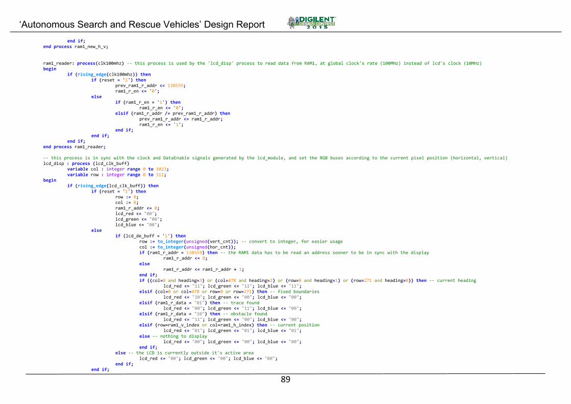
‘Autonomous Search and Rescue Vehicles’ Design Report
89
end if; end process ram1_new_h_v; ram1_reader: process(clk100mhz) -- this process is used by the 'lcd_disp' process to read data from RAM1, at global clock's rate (100MHz) instead of lcd's clock (10MHz) begin if (rising_edge(clk100mhz)) then if (reset = '1') then prev_ram1_r_addr <= 130559; ram1_r_en <= '0'; else if (ram1_r_en = '1') then ram1_r_en <= '0'; elsif (ram1_r_addr /= prev_ram1_r_addr) then prev_ram1_r_addr <= ram1_r_addr; ram1_r_en <= '1'; end if; end if; end if; end process ram1_reader; -- this process is in sync with the clock and DataEnable signals generated by the lcd_module, and set the RGB buses according to the current pixel position (horizontal, vertical) lcd_disp : process (lcd_clk_buff) variable col : integer range 0 to 1023; variable row : integer range 0 to 511; begin if (rising_edge(lcd_clk_buff)) then if (reset = '1') then row := 0; col := 0; ram1_r_addr <= 0; lcd_red <= "00"; lcd_green <= "00"; lcd_blue <= "00"; else if (lcd_de_buff = '1') then row := to_integer(unsigned(vert_cnt)); -- convert to integer, for easier usage col := to_integer(unsigned(hor_cnt)); if (ram1_r_addr = 130559) then -- the RAM1 data has to be read an address sooner to be in sync with the display ram1_r_addr <= 0; else ram1_r_addr <= ram1_r_addr + 1; end if; if ((col=0 and heading=3) or (col=478 and heading=2) or (row=0 and heading=1) or (row=271 and heading=0)) then -- current heading lcd_red <= "11"; lcd_green <= "11"; lcd_blue <= "11"; elsif (col=0 or col=478 or row=0 or row=271) then -- fixed boundaries lcd_red <= "10"; lcd_green <= "00"; lcd_blue <= "00"; elsif (ram1_r_data = "01") then -- trace found lcd_red <= "00"; lcd_green <= "11"; lcd_blue <= "00"; elsif (ram1_r_data = "10") then -- obstacle found lcd_red <= "11"; lcd_green <= "00"; lcd_blue <= "00"; elsif (row=ram1_v_index or col=ram1_h_index) then -- current position lcd_red <= "01"; lcd_green <= "01"; lcd_blue <= "01"; else -- nothing to display lcd_red <= "00"; lcd_green <= "00"; lcd_blue <= "00"; end if; else -- the LCD is currently outside it's active area lcd_red <= "00"; lcd_green <= "00"; lcd_blue <= "00"; end if; end if;

‘Autonomous Search and Rescue Vehicles’ Design Report
90
end if; end process lcd_disp; -- to implement the data vector RAM1 and RAM2, the Xilinx synthesis tools expects this syntax for a dual port block-RAM (if declared differently, it will be implemented using flip-flops - extremely inefficient and slow) ram1_write: process (clk100mhz) -- allow writing to RAM1 begin if (rising_edge(clk100mhz)) then if (ram1_w_en = '1') then if (ram1_wen = '1') then ram1(ram1_w_addr) <= ram1_w_data; end if; end if; end if; end process ram1_write; ram1_read: process (clk100mhz) -- allow reading from RAM1 begin if (rising_edge(clk100mhz)) then if (ram1_r_en = '1') then ram1_r_data <= ram1(ram1_r_addr); end if; end if; end process ram1_read; ram2_write: process (clk100mhz) -- allow writing to RAM2 begin if (rising_edge(clk100mhz)) then if (ram2_w_en = '1') then if (ram2_wen = '1') then ram2(ram2_w_addr) <= ram2_w_data; end if; end if; end if; end process ram2_write; ram2_read: process (clk100mhz) -- allow reading from RAM2 begin if (rising_edge(clk100mhz)) then if (ram2_r_en = '1') then ram2_r_data <= ram2(ram2_r_addr); end if; end if; end process ram2_read; -- The following are used only for debugging uses, as it displays on the 7 segment display data aquired during the 'Search' state (see 'FSM' process) led <= sw or "00000000000" & btn; -- all 16 LEDs are directly driven by the 16 switches rgb <= motor_done & us_done & rf_motor_done & ir_tmp_done & ir_tmp_done & amb_tmp_done; -- the two RGB LEDs are used to visually check the state of the various finite-state modules seg7_data <= ir_data & temp_data_disp & "0000" when (sw(1) = '1') else "00000000" & us_data_disp; -- using switch 0, toggle between displaying temperature or ultrasound measurement amb_tmp_display : process (amb_tmp_done) -- 'decompose' the 13-bit temperature reading into individual BCD digits for the 7 segment display variable dig1, dig2, dig3 : integer range 0 to 9; variable tmp : integer range 0 to 65535; begin if (rising_edge(amb_tmp_done)) then tmp := to_integer(signed(amb_tmp_data)) / 16; dig1 := tmp mod 10; -- this method is rather inefficient, but is used only for debugging dig2 := (tmp/10) mod 10; dig3 := (tmp/100) mod 10; temp_data_disp <= std_logic_vector(to_unsigned(dig3,4)) & std_logic_vector(to_unsigned(dig2,4)) & std_logic_vector(to_unsigned(dig1,4)); -- again, quite inefficient but it works

‘Autonomous Search and Rescue Vehicles’ Design Report
91
end if; end process amb_tmp_display; us_display: process (us_done) -- 'decompose' the three 12-bit ultrasound distance measurement into individual BCD digits for the 7 segment display variable dig1, dig2, dig3, dig4, dig5, dig6 : integer range 0 to 9; variable period1, period2, period3 : integer range 0 to 4095; begin if (rising_edge(us_done)) then period3 := to_integer(unsigned(us_data (35 downto 24))) / 58; period2 := to_integer(unsigned(us_data (23 downto 12))) / 58; period1 := to_integer(unsigned(us_data (11 downto 0))) / 58; dig1 := period1 mod 10; dig2 := (period1/10) mod 10; dig3 := period2 mod 10; dig4 := (period2/10) mod 10; dig5 := period3 mod 10; dig6 := (period3/10) mod 10; us_data_disp <= std_logic_vector(to_unsigned(dig6,4)) & std_logic_vector(to_unsigned(dig5,4)) & std_logic_vector(to_unsigned(dig4,4)) & std_logic_vector(to_unsigned(dig3,4)) & std_logic_vector(to_unsigned(dig2,4)) & std_logic_vector(to_unsigned(dig1,4)); end if; end process us_display; end behavioral;
4.2.11. ultrasound.vhd ---------------------------------------------------------------------------------------------------- ---- TITLE: Three HC-SR04 ultrasound distance measurement devices (ultrasound.vhd) ---- REVISION: 1.0 (10.05.2015) ---- DEPENDENCIES: None ---- REQUIRENMENTS: None ---- DEVICE, ENVIRONMENT: Digilent Nexys4DDR, Xilinx Vivado 2014.4 ---- CONTACT: Pop Mihnea Vlad ([email protected]), Tatar Alex ([email protected]) ---------------------------------------------------------------------------------------------------- ---- DESCRIPTION: This module controls three HC-SR04 devices, including the triggering and echo -- time measurement phases. Each sensor is triggered after the previous one has finished measuring. ---------------------------------------------------------------------------------------------------- library ieee; use ieee.std_logic_1164.all; use ieee.numeric_std.all; -- used for the 'std_logic_vector' and 'to_unsigned' type conversion entity ultrasound is port ( clk100mhz_in : in std_logic; -- 100MHz global clock reset_in : in std_logic; -- active-high us_trig_out : out std_logic_vector (2 downto 0); -- active-high us_echo_in : in std_logic_vector (2 downto 0); -- active-high start_in : in std_logic; -- active-high done_out : out std_logic; -- active-high data_out : out std_logic_vector(35 downto 0)); -- all three 12-bit distance measurements end ultrasound; architecture behavioral of ultrasound is type data_array is array(integer range 0 to 2) of std_logic_vector(11 downto 0); signal data_buff : data_array; -- three 12-bit distance measurements data vectors signal done : std_logic := '1'; -- signals that this module has finished measuring from all three sensors and data_out is refreshed signal clk1mhz : std_logic; -- 1MHz clock required to accurately measure each of the HC-SR04's output period at a resolution of 1us begin data_out <= data_buff(2) & data_buff(1) & data_buff(0); -- connects the internal measurements data vectors to the single module data output vector done_out <= done; -- connects the internal 'done' signal to the module output 'done_out'

‘Autonomous Search and Rescue Vehicles’ Design Report
92
clk_div : process (clk100mhz_in) -- 100MHz to 1MHz, 50% duty cycle, clock divider variable count : integer range 0 to 49 := 0; -- (100.000.000/1.000.000)/2 - 1 begin if (rising_edge(clk100mhz_in)) then if (reset_in = '1') then -- resets all signals used by this process clk1mhz <= '0'; count := 0; else if (count = 49) then clk1mhz <= not clk1mhz; -- to obtain a 50% duty cycle, the clk1MHz signal is negated at each 50 cycles (or 2MHz), resulting an 1MHz clock count := 0; else count := count + 1; end if; end if; end if; end process clk_div; ultrasound_ctrl : process (clk1mhz) variable cs : std_logic_vector (2 downto 0) := "001"; -- 'chip select' - each sensor is selected in succession variable triggered, echoed : std_logic := '0'; -- internal state for each sensor (trigger set, echo received) variable period : integer range 0 to 32767 := 0; -- period of time the sensor returned variable count : integer range 0 to 10 := 0; -- to send a 10usec trigger signal, a counter is used (10 cycles of 1MHz = 10usec); variable nr : integer range 0 to 2 := 0; -- sensor number (to assign measurement data to the respective sensor) begin if (rising_edge(clk1mhz)) then if (reset_in = '1') then done <= '1'; count := 0; cs := "001"; triggered := '0'; echoed := '0'; period := 0; nr := 0; data_buff(2) <= (others => '0'); data_buff(1) <= (others => '0'); data_buff(0) <= (others => '0'); us_trig_out <= "000"; else if (start_in = '1' and done = '1') then -- if done, wait for the start signal done <= '0'; elsif (done = '0') then -- if not done, continue the state machine if (triggered = '0') then -- trigger not sent yet if (count = 10) then -- 10uSecs passed, go to echo measurement phase us_trig_out <= "000"; count := 0; triggered := '1'; period := 0; echoed := '0'; else -- continue sending the trigger signal us_trig_out <= cs; count := count + 1; end if; else -- echo measurement if (us_echo_in = cs) then -- wait for the echo to get pulled up, signifying the start of the period measurement echoed := '1'; end if; if (echoed = '1') then if (us_echo_in = cs) then -- if the echo is still high, continue counting the uSecs
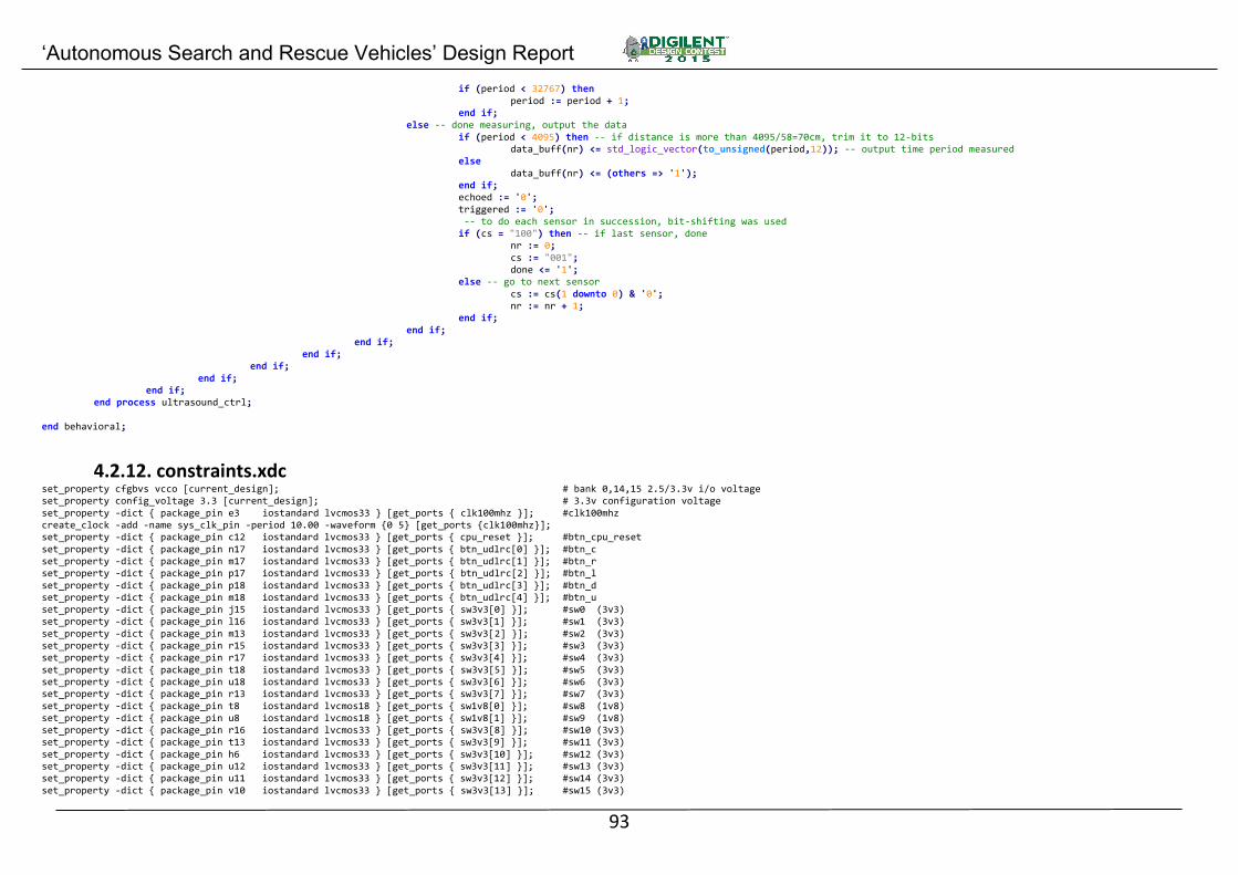
‘Autonomous Search and Rescue Vehicles’ Design Report
93
if (period < 32767) then period := period + 1; end if; else -- done measuring, output the data if (period < 4095) then -- if distance is more than 4095/58=70cm, trim it to 12-bits data_buff(nr) <= std_logic_vector(to_unsigned(period,12)); -- output time period measured else data_buff(nr) <= (others => '1'); end if; echoed := '0'; triggered := '0'; -- to do each sensor in succession, bit-shifting was used if (cs = "100") then -- if last sensor, done nr := 0; cs := "001"; done <= '1'; else -- go to next sensor cs := cs(1 downto 0) & '0'; nr := nr + 1; end if; end if; end if; end if; end if; end if; end if; end process ultrasound_ctrl; end behavioral;
4.2.12. constraints.xdc set_property cfgbvs vcco [current_design]; # bank 0,14,15 2.5/3.3v i/o voltage set_property config_voltage 3.3 [current_design]; # 3.3v configuration voltage set_property -dict { package_pin e3 iostandard lvcmos33 } [get_ports { clk100mhz }]; #clk100mhz create_clock -add -name sys_clk_pin -period 10.00 -waveform {0 5} [get_ports {clk100mhz}]; set_property -dict { package_pin c12 iostandard lvcmos33 } [get_ports { cpu_reset }]; #btn_cpu_reset set_property -dict { package_pin n17 iostandard lvcmos33 } [get_ports { btn_udlrc[0] }]; #btn_c set_property -dict { package_pin m17 iostandard lvcmos33 } [get_ports { btn_udlrc[1] }]; #btn_r set_property -dict { package_pin p17 iostandard lvcmos33 } [get_ports { btn_udlrc[2] }]; #btn_l set_property -dict { package_pin p18 iostandard lvcmos33 } [get_ports { btn_udlrc[3] }]; #btn_d set_property -dict { package_pin m18 iostandard lvcmos33 } [get_ports { btn_udlrc[4] }]; #btn_u set_property -dict { package_pin j15 iostandard lvcmos33 } [get_ports { sw3v3[0] }]; #sw0 (3v3) set_property -dict { package_pin l16 iostandard lvcmos33 } [get_ports { sw3v3[1] }]; #sw1 (3v3) set_property -dict { package_pin m13 iostandard lvcmos33 } [get_ports { sw3v3[2] }]; #sw2 (3v3) set_property -dict { package_pin r15 iostandard lvcmos33 } [get_ports { sw3v3[3] }]; #sw3 (3v3) set_property -dict { package_pin r17 iostandard lvcmos33 } [get_ports { sw3v3[4] }]; #sw4 (3v3) set_property -dict { package_pin t18 iostandard lvcmos33 } [get_ports { sw3v3[5] }]; #sw5 (3v3) set_property -dict { package_pin u18 iostandard lvcmos33 } [get_ports { sw3v3[6] }]; #sw6 (3v3) set_property -dict { package_pin r13 iostandard lvcmos33 } [get_ports { sw3v3[7] }]; #sw7 (3v3) set_property -dict { package_pin t8 iostandard lvcmos18 } [get_ports { sw1v8[0] }]; #sw8 (1v8) set_property -dict { package_pin u8 iostandard lvcmos18 } [get_ports { sw1v8[1] }]; #sw9 (1v8) set_property -dict { package_pin r16 iostandard lvcmos33 } [get_ports { sw3v3[8] }]; #sw10 (3v3) set_property -dict { package_pin t13 iostandard lvcmos33 } [get_ports { sw3v3[9] }]; #sw11 (3v3) set_property -dict { package_pin h6 iostandard lvcmos33 } [get_ports { sw3v3[10] }]; #sw12 (3v3) set_property -dict { package_pin u12 iostandard lvcmos33 } [get_ports { sw3v3[11] }]; #sw13 (3v3) set_property -dict { package_pin u11 iostandard lvcmos33 } [get_ports { sw3v3[12] }]; #sw14 (3v3) set_property -dict { package_pin v10 iostandard lvcmos33 } [get_ports { sw3v3[13] }]; #sw15 (3v3)

‘Autonomous Search and Rescue Vehicles’ Design Report
94
set_property -dict { package_pin h17 iostandard lvcmos33 } [get_ports { led[0] }]; #led0 set_property -dict { package_pin k15 iostandard lvcmos33 } [get_ports { led[1] }]; #led1 set_property -dict { package_pin j13 iostandard lvcmos33 } [get_ports { led[2] }]; #led2 set_property -dict { package_pin n14 iostandard lvcmos33 } [get_ports { led[3] }]; #led3 set_property -dict { package_pin r18 iostandard lvcmos33 } [get_ports { led[4] }]; #led4 set_property -dict { package_pin v17 iostandard lvcmos33 } [get_ports { led[5] }]; #led5 set_property -dict { package_pin u17 iostandard lvcmos33 } [get_ports { led[6] }]; #led6 set_property -dict { package_pin u16 iostandard lvcmos33 } [get_ports { led[7] }]; #led7 set_property -dict { package_pin v16 iostandard lvcmos33 } [get_ports { led[8] }]; #led8 set_property -dict { package_pin t15 iostandard lvcmos33 } [get_ports { led[9] }]; #led9 set_property -dict { package_pin u14 iostandard lvcmos33 } [get_ports { led[10] }]; #led10 set_property -dict { package_pin t16 iostandard lvcmos33 } [get_ports { led[11] }]; #led11 set_property -dict { package_pin v15 iostandard lvcmos33 } [get_ports { led[12] }]; #led12 set_property -dict { package_pin v14 iostandard lvcmos33 } [get_ports { led[13] }]; #led13 set_property -dict { package_pin v12 iostandard lvcmos33 } [get_ports { led[14] }]; #led14 set_property -dict { package_pin v11 iostandard lvcmos33 } [get_ports { led[15] }]; #led15 set_property -dict { package_pin r12 iostandard lvcmos33 } [get_ports { rgb[0] }]; #led16_b set_property -dict { package_pin m16 iostandard lvcmos33 } [get_ports { rgb[1] }]; #led16_g set_property -dict { package_pin n15 iostandard lvcmos33 } [get_ports { rgb[2] }]; #led16_r set_property -dict { package_pin g14 iostandard lvcmos33 } [get_ports { rgb[3] }]; #led17_b set_property -dict { package_pin r11 iostandard lvcmos33 } [get_ports { rgb[4] }]; #led17_g set_property -dict { package_pin n16 iostandard lvcmos33 } [get_ports { rgb[5] }]; #led17_r set_property -dict { package_pin t10 iostandard lvcmos33 } [get_ports { cat[0] }]; #7seg_sega set_property -dict { package_pin r10 iostandard lvcmos33 } [get_ports { cat[1] }]; #7seg_segb set_property -dict { package_pin k16 iostandard lvcmos33 } [get_ports { cat[2] }]; #7seg_segc set_property -dict { package_pin k13 iostandard lvcmos33 } [get_ports { cat[3] }]; #7seg_segd set_property -dict { package_pin p15 iostandard lvcmos33 } [get_ports { cat[4] }]; #7seg_sege set_property -dict { package_pin t11 iostandard lvcmos33 } [get_ports { cat[5] }]; #7seg_segf set_property -dict { package_pin l18 iostandard lvcmos33 } [get_ports { cat[6] }]; #7seg_segg set_property -dict { package_pin h15 iostandard lvcmos33 } [get_ports { dp }]; #7seg_dp set_property -dict { package_pin j17 iostandard lvcmos33 } [get_ports { an[0] }]; #7seg_dig0 set_property -dict { package_pin j18 iostandard lvcmos33 } [get_ports { an[1] }]; #7seg_dig1 set_property -dict { package_pin t9 iostandard lvcmos33 } [get_ports { an[2] }]; #7seg_dig2 set_property -dict { package_pin j14 iostandard lvcmos33 } [get_ports { an[3] }]; #7seg_dig3 set_property -dict { package_pin p14 iostandard lvcmos33 } [get_ports { an[4] }]; #7seg_dig4 set_property -dict { package_pin t14 iostandard lvcmos33 } [get_ports { an[5] }]; #7seg_dig5 set_property -dict { package_pin k2 iostandard lvcmos33 } [get_ports { an[6] }]; #7seg_dig6 set_property -dict { package_pin u13 iostandard lvcmos33 } [get_ports { an[7] }]; #7seg_dig7 set_property -dict { package_pin c15 iostandard lvcmos33 } [get_ports { tmp_sda }]; #tmp_sda set_property -dict { package_pin c14 iostandard lvcmos33 } [get_ports { tmp_scl }]; #tmp_scl set_property -dict { package_pin c17 iostandard lvcmos33 } [get_ports { us_trig[0] }]; #ja[1] set_property -dict { package_pin d18 iostandard lvcmos33 } [get_ports { us_trig[1] }]; #ja[2] set_property -dict { package_pin e18 iostandard lvcmos33 } [get_ports { us_trig[2] }]; #ja[3] set_property -dict { package_pin g17 iostandard lvcmos33 } [get_ports { us_echo[0] }]; #ja[4] set_property -dict { package_pin d17 iostandard lvcmos33 } [get_ports { us_echo[1] }]; #ja[7] set_property -dict { package_pin e17 iostandard lvcmos33 } [get_ports { us_echo[2] }]; #ja[8] set_property -dict { package_pin f18 iostandard lvcmos33 } [get_ports { magn_sda }]; #ja[9] set_property -dict { package_pin g18 iostandard lvcmos33 } [get_ports { magn_scl }]; #ja[10] set_property -dict { package_pin d14 iostandard lvcmos33 } [get_ports { ml_fb[0] }]; #jb[1] set_property -dict { package_pin f16 iostandard lvcmos33 } [get_ports { ml_fb[1] }]; #jb[2] set_property -dict { package_pin g16 iostandard lvcmos33 } [get_ports { mr_fb[0] }]; #jb[3] set_property -dict { package_pin h14 iostandard lvcmos33 } [get_ports { mr_fb[1] }]; #jb[4] set_property -dict { package_pin e16 iostandard lvcmos33 } [get_ports { irtmp_miso }]; #jb[7] set_property -dict { package_pin f13 iostandard lvcmos33 } [get_ports { irtmp_clk }]; #jb[8] set_property -dict { package_pin g13 iostandard lvcmos33 } [get_ports { irtmp_ss }]; #jb[9] set_property -dict { package_pin h16 iostandard lvcmos33 } [get_ports { irtmp_pwr }]; #jb[10] set_property -dict { package_pin k1 iostandard lvcmos33 } [get_ports { magn_drdy }]; #jc[1] set_property -dict { package_pin f6 iostandard lvcmos33 } [get_ports { rf_data }]; #jc[2] set_property -dict { package_pin j2 iostandard lvcmos33 } [get_ports { ml_en }]; #jc[3] set_property -dict { package_pin g6 iostandard lvcmos33 } [get_ports { mr_en }]; #jc[4]

‘Autonomous Search and Rescue Vehicles’ Design Report
95
set_property -dict { package_pin e7 iostandard lvcmos33 } [get_ports { ml_in[0] }]; #jc[7] set_property -dict { package_pin j3 iostandard lvcmos33 } [get_ports { ml_in[1] }]; #jc[8] set_property -dict { package_pin j4 iostandard lvcmos33 } [get_ports { mr_in[0] }]; #jc[9] set_property -dict { package_pin e6 iostandard lvcmos33 } [get_ports { mr_in[1] }]; #jc[10] set_property -dict { package_pin h4 iostandard lvcmos33 } [get_ports { lcd_de }]; #jd[1] set_property -dict { package_pin h1 iostandard lvcmos33 } [get_ports { lcd_clk }]; #jd[2] set_property -dict { package_pin g1 iostandard lvcmos33 } [get_ports { lcd_red[0] }]; jd[3] set_property -dict { package_pin g3 iostandard lvcmos33 } [get_ports { lcd_red[1] }]; jd[4] set_property -dict { package_pin h2 iostandard lvcmos33 } [get_ports { lcd_green[0] }]; jd[7] set_property -dict { package_pin g4 iostandard lvcmos33 } [get_ports { lcd_green[1] }]; jd[8] set_property -dict { package_pin g2 iostandard lvcmos33 } [get_ports { lcd_blue[0] }]; jd[9] set_property -dict { package_pin f3 iostandard lvcmos33 } [get_ports { lcd_blue[1] }]; jd[10]