Embed Size (px)
Citation preview
Autonomous Navigation of Hexapod Robots With Vision-basedController Adaptation
Marko Bjelonic1∗, Timon Homberger2∗, Navinda Kottege3, Paulo Borges3, Margarita Chli4, Philipp Beckerle5
Abstract— This work introduces a novel hybrid controlarchitecture for a hexapod platform (Weaver), making itcapable of autonomously navigating in uneven terrain. Themain contribution stems from the use of vision-based exte-roceptive terrain perception to adapt the robot’s locomotionparameters. Avoiding computationally expensive path planningfor the individual foot tips, the adaptation controller enablesthe robot to reactively adapt to the surface structure it ismoving on. The virtual stiffness, which mainly characterizesthe behavior of the legs’ impedance controller is adaptedaccording to visually perceived terrain properties. To furtherimprove locomotion, the frequency and height of the robot’sstride are similarly adapted. Furthermore, novel methods forterrain characterization and a keyframe based visual-inertialodometry algorithm are combined to generate a spatial map ofterrain characteristics. Localization via odometry also allowsfor autonomous missions on variable terrain by incorporatingglobal navigation and terrain adaptation into one controlarchitecture. Autonomous runs on a testbed with variableterrain types illustrate that adaptive stride and impedancebehavior decreases the cost of transport by 30 % comparedto a non-adaptive approach and simultaneously increases bodystability (up to 88 % on even terrain and by 54 % on uneventerrain). Weaver is able to freely explore outdoor environmentsas it is completely free of external tethers, as shown in theexperiments.
I. INTRODUCTION
Locomotion of mobile robots on rough terrain withoutprior information of the terrain structure is an importanttask. It is required for planetary exploration [1], missionsin disaster zones [2], mining [3], and others. In this field,legged robots have gained increased attention, due to theirmechanical ability to move on various types of challengingterrain [4].
Legged robots need to control the contact between thefoot tips and the ground in order to ensure stability onrough terrain. Both reactive and proactive control approaches
1 M. Bjelonic is with the Robotic Systems Lab, ETH Zurich, 8092Zurich, Switzerland and was with the Autonomous Systems Group, CSIRO,Pullenvale, QLD 4069, Australia at the time of this work.
2 T. Homberger is a student at the Department of Mechanical andProcess Engineering, ETH Zurich, 8092 Zurich, Switzerland was with theAutonomous Systems Group, CSIRO, Pullenvale, QLD 4069, Australia atthe time of this work.
3 N. Kottege and P. Borges are with the Autonomous Systems Group,CSIRO, Pullenvale, QLD 4069, Australia. Correspondence should be ad-dressed to [email protected]
4 M. Chli is with the Vision for Robotics Lab, ETH Zurich, 8092 Zurich,Switzerland.
5 P. Beckerle is with the Institute for Mechatronic Systems in MechanicalEngineering, Technische Universitat Darmstadt, 64287 Darmstadt, Germany.
∗ These authors contributed equally to this work.
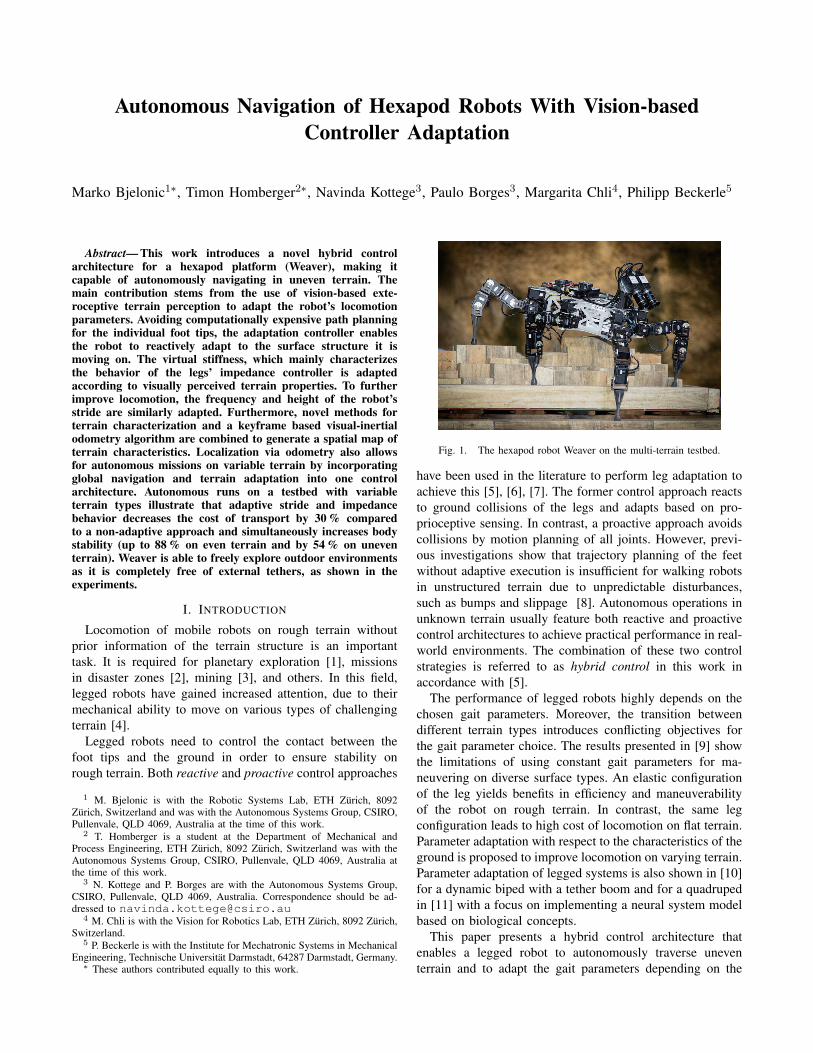
Fig. 1. The hexapod robot Weaver on the multi-terrain testbed.
have been used in the literature to perform leg adaptation toachieve this [5], [6], [7]. The former control approach reactsto ground collisions of the legs and adapts based on pro-prioceptive sensing. In contrast, a proactive approach avoidscollisions by motion planning of all joints. However, previ-ous investigations show that trajectory planning of the feetwithout adaptive execution is insufficient for walking robotsin unstructured terrain due to unpredictable disturbances,such as bumps and slippage [8]. Autonomous operations inunknown terrain usually feature both reactive and proactivecontrol architectures to achieve practical performance in real-world environments. The combination of these two controlstrategies is referred to as hybrid control in this work inaccordance with [5].
The performance of legged robots highly depends on thechosen gait parameters. Moreover, the transition betweendifferent terrain types introduces conflicting objectives forthe gait parameter choice. The results presented in [9] showthe limitations of using constant gait parameters for ma-neuvering on diverse surface types. An elastic configurationof the leg yields benefits in efficiency and maneuverabilityof the robot on rough terrain. In contrast, the same legconfiguration leads to high cost of locomotion on flat terrain.Parameter adaptation with respect to the characteristics of theground is proposed to improve locomotion on varying terrain.Parameter adaptation of legged systems is also shown in [10]for a dynamic biped with a tether boom and for a quadrupedin [11] with a focus on implementing a neural system modelbased on biological concepts.
This paper presents a hybrid control architecture thatenables a legged robot to autonomously traverse uneventerrain and to adapt the gait parameters depending on the
terrain characteristics. The robot’s autonomy is achieved byusing visual-inertial odometry on a custom built hardwaresetup. Moreover, the proposed controller is evaluated on areal hexapod robot, Weaver (Fig. 1). The hybrid controllerintroduces:
• Efficient and stable locomotion by adapting strideheight, stride frequency and virtual stiffness.
• Exteroceptive terrain perception method for parameteradaptation of a reactive control architecture.
• Increased autonomy by combining a global navigationsystem with controller adaptation.
The paper is organized as follows: The hybrid controlleris presented in Section III after introducing Weaver in Sec-tion II. The experimental results in Section IV are discussedby Section V and Section VI concludes the paper.
II. HEXAPOD PLATFORM WEAVER
Weaver was specially developed in-house for rough terraintraversal and introduced in [9]. One of the key differences toother hexapod robots is the five joints per leg. This allowsefficient and stable locomotion on inclined surfaces, as thelast link of the robot’s leg can be aligned with the gravityvector. In addition, Weaver with its 30 Degrees of freedom(DoF) controls the body pose on inclinations to increasethe Normalized Energy Stability Margin [12]. The directionof the gravity vector is determined by measurements of anInertial Measurement Unit (IMU). The inclination controller,coupled with an impedance controller of the foot tip positionin Cartesian space improves Weaver’s locomotion on uneventerrain. It reacts to forces imposed by adapting the positionof the foot tip.
The hybrid controller presented in this paper combines theexteroceptive terrain perception introduced in [13] with theproprioceptive controller introduced in [9] and implements anadaptation controller which adapts not only the leg stiffnessbut also the stride height and stride frequency. The followingsection further describes the hybrid control architecture.
III. HYBRID CONTROLLLER
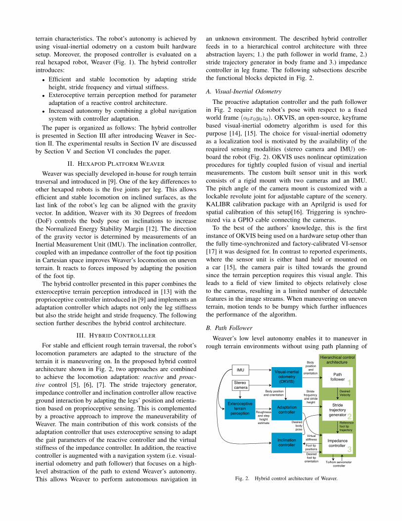
For stable and efficient rough terrain traversal, the robot’slocomotion parameters are adapted to the structure of theterrain it is maneuvering on. In the proposed hybrid controlarchitecture shown in Fig. 2, two approaches are combinedto achieve the locomotion adaptation: reactive and proac-tive control [5], [6], [7]. The stride trajectory generator,impedance controller and inclination controller allow reactiveground interaction by adapting the legs’ position and orienta-tion based on proprioceptive sensing. This is complementedby a proactive approach to improve the maneuverability ofWeaver. The main contribution of this work consists of theadaptation controller that uses exteroceptive sensing to adaptthe gait parameters of the reactive controller and the virtualstiffness of the impedance controller. In addition, the reactivecontroller is augmented with a navigation system (i.e. visual-inertial odometry and path follower) that focuses on a high-level abstraction of the path to extend Weaver’s autonomy.This allows Weaver to perform autonomous navigation in
an unknown environment. The described hybrid controllerfeeds in to a hierarchical control architecture with threeabstraction layers; 1.) the path follower in world frame, 2.)stride trajectory generator in body frame and 3.) impedancecontroller in leg frame. The following subsections describethe functional blocks depicted in Fig. 2.
A. Visual-Inertial Odometry
The proactive adaptation controller and the path followerin Fig. 2 require the robot’s pose with respect to a fixedworld frame (o0x0y0z0). OKVIS, an open-source, keyframebased visual-inertial odometry algorithm is used for thispurpose [14], [15]. The choice for visual-inertial odometryas a localization tool is motivated by the availability of therequired sensing modalities (stereo camera and IMU) on-board the robot (Fig. 2). OKVIS uses nonlinear optimizationprocedures for tightly coupled fusion of visual and inertialmeasurements. The custom built sensor unit in this workconsists of a rigid mount with two cameras and an IMU.The pitch angle of the camera mount is customized with alockable revolute joint for adjustable capture of the scenery.KALIBR calibration package with an Aprilgrid is used forspatial calibration of this setup[16]. Triggering is synchro-nized via a GPIO cable connecting the cameras.
To the best of the authors’ knowledge, this is the firstinstance of OKVIS being used on a hardware setup other thanthe fully time-synchronized and factory-calibrated VI-sensor[17] it was designed for. In contrast to reported experiments,where the sensor unit is either hand held or mounted ona car [15], the camera pair is tilted towards the groundsince the terrain perception requires this visual angle. Thisleads to a field of view limited to objects relatively closeto the cameras, resulting in a limited number of detectablefeatures in the image streams. When maneuvering on uneventerrain, motion tends to be bumpy which further influencesthe performance of the algorithm.
B. Path Follower
Weaver’s low level autonomy enables it to maneuver inrough terrain environments without using path planning of
Hierarchical controlarchitecture
Pathfollower
Stridetrajectorygenerator
Desiredbodypose
IMU
Body position
andorientation
Stereocamera
Visual-inertialodometry(OKVIS)
Adaptationcontroller
Inclinationcontroller
Exteroceptiveterrain
perception
Impedancecontroller
Roughnessand step
heightestimate
Stride frequency and stride
height
Foot tip positions
Referencefoot tiptrajectory
Body positionand orientation
Virtualstiffness
Desiredfoot tip
orientation
DesiredVelocity
To/from servomotor controller
1
2
3
Fig. 2. Hybrid control architecture of Weaver.
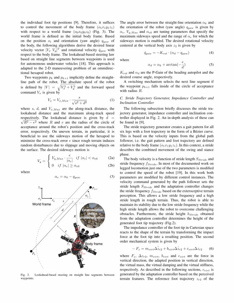
the individual foot tip positions [9]. Therefore, it sufficesto control the movement of the body frame (o1x1y1z1)with respect to a world frame (o0x0y0z0) (Fig. 3). Theworld frame is defined as the initial body frame. Basedon the position o1 and orientation (yaw angle) qyaw ofthe body, the following algorithms derive the desired linearvelocity vector [Vx Vy]T and rotational velocity qyaw withrespect to the body frame. The lookahead-based steering lawbased on straight line segments between waypoints is usedfor autonomous underwater vehicles [18]. This approach isadapted to the 2-D maneuvering problem of an omnidirec-tional hexapod robot.
Two waypoints pk and pk+1 implicitly define the straight-line path of the robot. The absolute speed of the robotis defined by |V | =
√V 2x + V 2
y and the forward speedcommand Vx is given by
Vx = Vx,Max ·s√
s2 + d2(1)
where s, d, and Vx,Max are the along-track distance, thelookahead distance and the maximum along-track speedrespectively. The lookahead distance is given by d =√R2 − e2 where R and e are the radius of the circle of
acceptance around the robot’s position and the cross-trackerror, respectively. On uneven terrain, in particular, it isbeneficial to use the sideways motion of the hexapod tominimize the cross-track error e since rough terrain inducesrandom disturbances due to slippage and moving objects onthe surface. The desired sideways motion is
Vy =
Vy,Max ·e
|αe|if |αe| < αe0 (2a)
0 if |αe| ≥ αe0 (2b)
whereαe = αk − qyaw (3)
x1
y1 o1
y0
x0World frame
Body frame
Exteroceptiveterrain
characterization
pk
pk+1
e
s
d
R
αk
V
qyaw
o0
Fig. 3. Lookahead-based steering on straight line segments betweenwaypoints.
The angle error between the straight-line orientation αk andthe orientation of the robot (yaw angle) qyaw is given byαe. Vy,Max and αe0 are tuning parameters that specify themaximum sideways speed and the range of αe for which thesideways motion is enabled. The desired rotational velocitycentered at the vertical body axis z2 is given by
qyaw = −Krot · (αd − qyaw) (4)
whereαd = αk + arctan(− e
d) (5)
Krot and αd are the P-Gain of the heading autopilot and thedesired course angle, respectively.
A switching mechanism selects the next line segment ifthe waypoint pk+1 falls inside of the circle of acceptancewith radius R.
C. Stride Trajectory Generator, Impedance Controller andInclination Controller
The following subsection briefly discusses the stride tra-jectory generator, impedance controller and inclination con-troller displayed in Fig. 2. An in-depth analysis of these canbe found in [9].
The stride trajectory generator creates a gait pattern for allsix legs with a foot trajectory in the form of a Bezier curve.This is based on the velocity inputs from the global pathfollower, i.e. the gait pattern and foot trajectory are definedrelative to the body frame (o1x1y1z1). In this context, a stridedescribes the combined movement of the swing and stancephase.
The body velocity is a function of stride length SStride andstride frequency fStride. In most of the documented work onlegged locomotion just one of the two parameters is modifiedto control the speed of the robot [19]. In this work bothparameters are modified by different control instances. Thevelocity command generated by the path follower sets thestride length SStride and the adaptation controller changesthe stride frequency fStride based on the exteroceptive terrainperception. This allows a low stride frequency and a highstride length in rough terrain. Thus, the robot is able tomaintain its stability due to the low stride frequency while thehigh stride length allows the robot to overcome challengingobstacles. Furthermore, the stride height hStride obtainedfrom the adaptation controller determines the height of thegenerated foot tip trajectory (Fig.2).
The impedance controller of the foot tip in Cartesian spacereacts to the shape of the terrain by transforming the impactforce at the foot tip into a resulting position. The secondorder mechanical system is given by
− Fz = mvirt¨∆zr2 + bvirt ˙∆zr2 + cvirt∆zr2 (6)
where Fz , ∆zr2, mvirt, bvirt and cvirt are the force invertical direction, the adapted position in vertical direction,the virtual mass, the virtual damping and the virtual stiffness,respectively. As described in the following sections, cvirt isgenerated by the adaptation controller based on the perceivedterrain features. The reference foot trajectory zr2 of the
stride trajectory generator is adapted by zd2 = zr2 −∆zr2.Weaver with its novel 5 DoF leg design is able to controlthe Cartesian position and orientation of the foot tip. The lastlink of the leg is aligned with the gravity vector using inversekinematics, i.e. the force ellipsoid of the foot tip is alignedwith the gravity vector. Thus, the gravitational force of therobot is supported with the least amount of effort [20]. Theinverse kinematics transforms the desired foot tip position[xd2 yd2 zd2]T and orientation [δd βd]T into desired motorpositions.
The inclination controller determines the orientation of thegravity vector with respect to the body frame (o1x1y1z1)based on the IMU signals and the six foot tip positions,i.e. the orientation of the gravity vector is described by twoangles δd and βd that constrain the space of solutions ofthe inverse kinematics. In addition, the inclination controllershifts the center of mass (CoM) of the robot on inclinedterrain to increase stability.
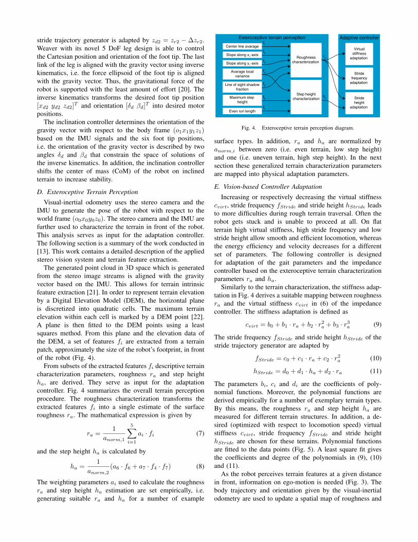
D. Exteroceptive Terrain Perception
Visual-inertial odometry uses the stereo camera and theIMU to generate the pose of the robot with respect to theworld frame (o0x0y0z0). The stereo camera and the IMU arefurther used to characterize the terrain in front of the robot.This analysis serves as input for the adaptation controller.The following section is a summary of the work conducted in[13]. This work contains a detailed description of the appliedstereo vision system and terrain feature extraction.
The generated point cloud in 3D space which is generatedfrom the stereo image streams is aligned with the gravityvector based on the IMU. This allows for terrain intrinsicfeature extraction [21]. In order to represent terrain elevationby a Digital Elevation Model (DEM), the horizontal planeis discretized into quadratic cells. The maximum terrainelevation within each cell is marked by a DEM point [22].A plane is then fitted to the DEM points using a leastsquares method. From this plane and the elevation data ofthe DEM, a set of features fi are extracted from a terrainpatch, approximately the size of the robot’s footprint, in frontof the robot (Fig. 4).
From subsets of the extracted features fi descriptive terraincharacterization parameters, roughness ra and step heightha, are derived. They serve as input for the adaptationcontroller. Fig. 4 summarizes the overall terrain perceptionprocedure. The roughness characterization transforms theextracted features fi into a single estimate of the surfaceroughness ra. The mathematical expression is given by
ra =1
anorm,1
5∑i=1
ai · fi (7)
and the step height ha is calculated by
ha =1
anorm,2(a6 · f6 + a7 · f4 · f7) (8)
The weighting parameters ai used to calculate the roughnessra and step height ha estimation are set empirically, i.e.generating suitable ra and ha for a number of example
Exteroceptive terrain perception Adaptive controllerCenter line avarage
f1
Slope along x1-axis
Slope along y1-axis
Avarage localvariance
Line of sight shadowfraction
Roughnesscharacterization
Virtualstiffness
adaptation
Maximum step height
Even run length
Step heightcharacterization Stride
heightadaptation
ra
ha
f2
f3
f4
f5
f6
f7
Stridefrequency
adaptation
Fig. 4. Exteroceptive terrain perception diagram.
surface types. In addition, ra and ha are normalized byanorm,i between zero (i.e. even terrain, low step height)and one (i.e. uneven terrain, high step height). In the nextsection these generalized terrain characterization parametersare mapped into physical adaptation parameters.
E. Vision-based Controller Adaptation
Increasing or respectively decreasing the virtual stiffnesscvirt, stride frequency fStride and stride height hStride leadsto more difficulties during rough terrain traversal. Often therobot gets stuck and is unable to proceed at all. On flatterrain high virtual stiffness, high stride frequency and lowstride height allow smooth and efficient locomotion, whereasthe energy efficiency and velocity decreases for a differentset of parameters. The following controller is designedfor adaptation of the gait parameters and the impedancecontroller based on the exteroceptive terrain characterizationparameters ra and ha.
Similarly to the terrain characterization, the stiffness adap-tation in Fig. 4 derives a suitable mapping between roughnessra and the virtual stiffness cvirt in (6) of the impedancecontroller. The stiffness adaptation is defined as
cvirt = b0 + b1 · ra + b2 · r2a + b3 · r3
a (9)
The stride frequency fStride and stride height hStride of thestride trajectory generator are adapted by
fStride = c0 + c1 · ra + c2 · r2a (10)
hStride = d0 + d1 · ha + d2 · ra (11)
The parameters bi, ci and di are the coefficients of poly-nomial functions. Moreover, the polynomial functions arederived empirically for a number of exemplary terrain types.By this means, the roughness ra and step height ha aremeasured for different terrain structures. In addition, a de-sired (optimized with respect to locomotion speed) virtualstiffness cvirt, stride frequency fStride and stride heighthStride are chosen for these terrains. Polynomial functionsare fitted to the data points (Fig. 5). A least square fit givesthe coefficients and degree of the polynomials in (9), (10)and (11).
As the robot perceives terrain features at a given distancein front, information on ego-motion is needed (Fig. 3). Thebody trajectory and orientation given by the visual-inertialodometry are used to update a spatial map of roughness and
Roughness estimation0 0.1 0.2 0.3 0.4 0.5 0.6 0.7 0.8 0.9 1
Adap
tatio
n pa
ram
eter
s(m
axim
um v
alue
ratio
) in
%
0
20
40
60
80
100
Virtual stiffnessStride frequencyStride height
Fig. 5. Polynomial function fit for nine exemplary terrain types from themulti-terrain testbed.
step height values in the world frame. A circular area aroundthe center of the body frame which is relevant for the robot’sfoot tip placement is searched for the highest roughness andstep height values. Thus, the most conservative set of gaitparameters is set so that the robot can safely traverse thegiven area.
IV. EXPERIMENTS AND RESULTS
A. Performance Criteria
The dimensionless energetic cost of transport (CoT) isa popular performance indicator for wheeled and leggedrobots. For more information about the cost of transportplease refer to [9], [23]. The instantaneous cost of transportCoT and the overall cost of transport over a travelleddistance CoT are given by
CoT =UI
mgv, CoT =
1n
n∑i=1
UiIi
mg∆x∆t
, (12)
where U is the voltage of the power supply, I is the instanta-neous current drawn from the power supply, m is the mass, gis the gravitational acceleration, v is the velocity of the robotand ∆t is the time needed for the travelled distance ∆x. TheCoT in this work captures the overall energy consumptionof the robot based on the voltage and current of the powersupply. This includes mechanical energy, heat dissipationand other losses like friction. The energy efficiency highlydepends on the characteristics of the servomotors (e.g. PIDgains, resistance, induction, reduction ratios). Since this workcompares the CoT of two control algorithms on the samerobotic platform, it is assumed that the influence of thesecharacteristics remain unchanged between evaluation runs.
The percentage reduction of variance Si comes from shipcontrol assessment [24] and it is given by
Si = 100 ·(
1− V ar(Xi,a)
V ar(Xi,na)
)(13)
where i is a place holder for the movement in pitch androll. The function V ar(·) is the variance and the variableXi is the set of observed values in radiant. The subscriptsa and na stand for adaptive and non-adaptive, respectively.Maximizing (13) leads to stable movement of the body.
B. Experimental Setup
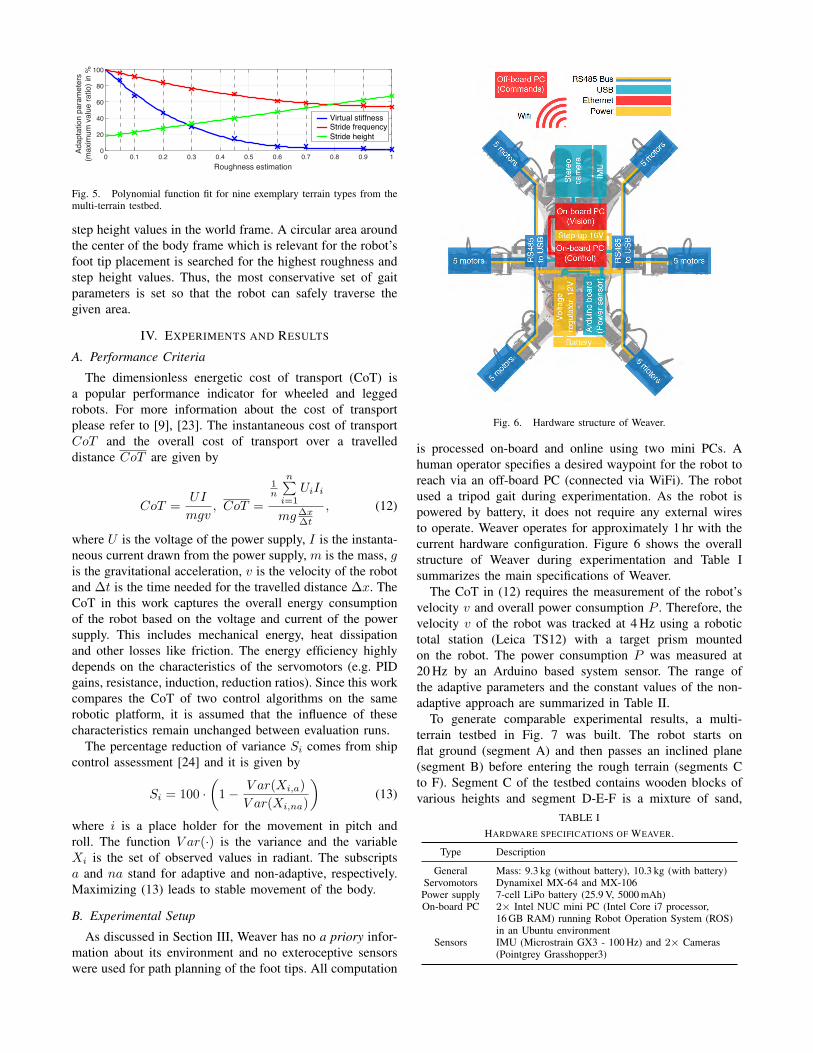
As discussed in Section III, Weaver has no a priory infor-mation about its environment and no exteroceptive sensorswere used for path planning of the foot tips. All computation
Fig. 6. Hardware structure of Weaver.
is processed on-board and online using two mini PCs. Ahuman operator specifies a desired waypoint for the robot toreach via an off-board PC (connected via WiFi). The robotused a tripod gait during experimentation. As the robot ispowered by battery, it does not require any external wiresto operate. Weaver operates for approximately 1 hr with thecurrent hardware configuration. Figure 6 shows the overallstructure of Weaver during experimentation and Table Isummarizes the main specifications of Weaver.
The CoT in (12) requires the measurement of the robot’svelocity v and overall power consumption P . Therefore, thevelocity v of the robot was tracked at 4 Hz using a robotictotal station (Leica TS12) with a target prism mountedon the robot. The power consumption P was measured at20 Hz by an Arduino based system sensor. The range ofthe adaptive parameters and the constant values of the non-adaptive approach are summarized in Table II.
To generate comparable experimental results, a multi-terrain testbed in Fig. 7 was built. The robot starts onflat ground (segment A) and then passes an inclined plane(segment B) before entering the rough terrain (segments Cto F). Segment C of the testbed contains wooden blocks ofvarious heights and segment D-E-F is a mixture of sand,
TABLE IHARDWARE SPECIFICATIONS OF WEAVER.
Type Description
General Mass: 9.3 kg (without battery), 10.3 kg (with battery)Servomotors Dynamixel MX-64 and MX-106Power supply 7-cell LiPo battery (25.9 V, 5000 mAh)On-board PC 2× Intel NUC mini PC (Intel Core i7 processor,
16 GB RAM) running Robot Operation System (ROS)in an Ubuntu environment
Sensors IMU (Microstrain GX3 - 100 Hz) and 2× Cameras(Pointgrey Grasshopper3)
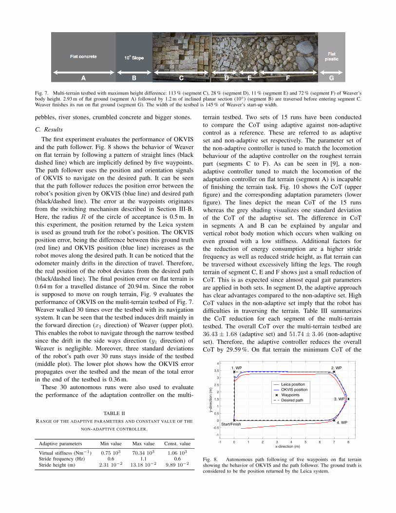
Fig. 7. Multi-terrain testbed with maximum height difference: 113 % (segment C), 28 % (segment D), 11 % (segment E) and 72 % (segment F) of Weaver’sbody height. 2.93 m of flat ground (segment A) followed by 1.2 m of inclined planar section (10◦) (segment B) are traversed before entering segment C.Weaver finishes its run on flat ground (segment G). The width of the testbed is 145 % of Weaver’s start-up width.
pebbles, river stones, crumbled concrete and bigger stones.
C. Results
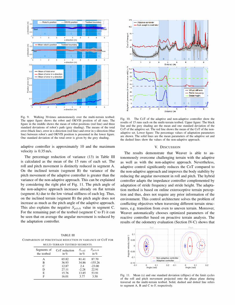
The first experiment evaluates the performance of OKVISand the path follower. Fig. 8 shows the behavior of Weaveron flat terrain by following a pattern of straight lines (blackdashed line) which are implicitly defined by five waypoints.The path follower uses the position and orientation signalsof OKVIS to navigate on the desired path. It can be seenthat the path follower reduces the position error between therobot’s position given by OKVIS (blue line) and desired path(black/dashed line). The error at the waypoints originatesfrom the switching mechanism described in Section III-B.Here, the radius R of the circle of acceptance is 0.5 m. Inthis experiment, the position returned by the Leica systemis used as ground truth for the robot’s position. The OKVISposition error, being the difference between this ground truth(red line) and OKVIS position (blue line) increases as therobot moves along the desired path. It can be noticed that theodometer mainly drifts in the direction of travel. Therefore,the real position of the robot deviates from the desired path(black/dashed line). The final position error on flat terrain is0.64 m for a travelled distance of 20.94 m. Since the robotis supposed to move on rough terrain, Fig. 9 evaluates theperformance of OKVIS on the mulit-terrain testbed of Fig. 7.Weaver walked 30 times over the testbed with its navigationsystem. It can be seen that the testbed induces drift mainly inthe forward direction (x1 direction) of Weaver (upper plot).This enables the robot to navigate through the narrow testbedsince the drift in the side ways direction (y1 direction) ofWeaver is negligible. Moreover, three standard deviationsof the robot’s path over 30 runs stays inside of the testbed(middle plot). The lower plot shows how the OKVIS errorpropagates over the testbed and the mean of the total errorin the end of the testbed is 0.36 m.
These 30 autonomous runs were also used to evaluatethe performance of the adaptation controller on the multi-
TABLE IIRANGE OF THE ADAPTIVE PARAMETERS AND CONSTANT VALUE OF THE
NON-ADAPTIVE CONTROLLER.
Adaptive parameters Min value Max value Const. value
Virtual stiffness (Nm−1) 0.75 103 70.34 103 1.06 103
Stride frequency (Hz) 0.6 1.1 0.6Stride height (m) 2.31 10−2 13.18 10−2 9.89 10−2
terrain testbed. Two sets of 15 runs have been conductedto compare the CoT using adaptive against non-adaptivecontrol as a reference. These are referred to as adaptiveset and non-adaptive set respectively. The parameter set ofthe non-adaptive controller is tuned to match the locomotionbehaviour of the adaptive controller on the roughest terrainpart (segments C to F). As can be seen in [9], a non-adaptive controller tuned to match the locomotion of theadaptation controller on flat terrain (segment A) is incapableof finishing the terrain task. Fig. 10 shows the CoT (upperfigure) and the corresponding adaptation parameters (lowerfigure). The lines depict the mean CoT of the 15 runswhereas the grey shading visualizes one standard deviationof the CoT of the adaptive set. The difference in CoTin segments A and B can be explained by angular andvertical robot body motion which occurs when walking oneven ground with a low stiffness. Additional factors forthe reduction of energy consumption are a higher stridefrequency as well as reduced stride height, as flat terrain canbe traversed without excessively lifting the legs. The roughterrain of segment C, E and F shows just a small reduction ofCoT. This is as expected since almost equal gait parametersare applied in both sets. In segment D, the adaptive approachhas clear advantages compared to the non-adaptive set. HighCoT values in the non-adaptive set imply that the robot hasdifficulties in traversing the terrain. Table III summarizesthe CoT reduction for each segment of the multi-terraintestbed. The overall CoT over the multi-terrain testbed are36.43 ± 1.68 (adaptive set) and 51.74 ± 3.46 (non-adaptiveset). Therefore, the adaptive controller reduces the overallCoT by 29.59 %. On flat terrain the minimum CoT of the
x-direction (m)-1 0 1 2 3 4 5 6 7 8
y-di
rect
ion
(m)
-1
-0.5
0
0.5
1
1.5
2
2.5
3
3.5
4
Start/Finish
1. WP 2. WP
3. WP
4. WP
Leica positionOKVIS positionWaypointsDesired path
Fig. 8. Autonomous path following of five waypoints on flat terrainshowing the behavior of OKVIS and the path follower. The ground truth isconsidered to be the position returned by the Leica system.
x-direction (m)0 1 2 3 4 5 6 7 8 9
y-di
rect
ion
(m)
-1
-0.5
0
0.5
1
Start Finish
A B C D E F G
Testbed boundaryRobot’s position OKVIS position
x-direction (m)0 1 2 3 4 5 6 7 8 9
y-di
rect
ion
(m)
-1
-0.5
0
0.5
1
Start
Testbed boundaryMean robot’s position
Finish
A B C D E F G
x-direction (m)0 1 2 3 4 5 6 7 8 9
Posi
tion
erro
r (m
)
0
0.1
0.2
0.3
0.4
0.5
0.6
Mean of total errorMean of error in x-directionMean of error in y-direction
A B C D E F G
Fig. 9. Walking 30-times autonomously over the multi-terrain testbed:The upper figure shows the robot and OKVIS position of all runs. Thefigure in the middle shows the mean of robot positions (red line) and threestandard deviations of robot’s path (grey shading). The means of the totalerror (black line), error in x-direction (red line) and error in y-direction (blueline) between robot’s and OKVIS position is presented in the lower figure.One standard deviation of the total error is given by the grey shading.
adaptive controller is approximately 10 and the maximumvelocity is 0.35 m/s.
The percentage reduction of variance (13) in Table IIIis calculated as the mean of the 15 runs of each set. Theroll and pitch movement is distinctly reduced in segment A.On the inclined terrain (segment B) the variance of thepitch movement of the adaptive controller is greater than thevariance of the non-adaptive approach. This can be explainedby considering the right plot of Fig. 11. The pitch angle ofthe non-adaptive approach increases already on flat terrain(segment A) due to the low virtual stiffness of each leg. Thus,on the inclined terrain (segment B) the pitch angle does notincrease as much as the pitch angle of the adaptive approach.This also explains the negative Spitch value in segment C.For the remaining part of the testbed (segment C to F) it canbe seen that on average the angular movement is reduced bythe adaptation controller.
TABLE IIICOMPARISON OF PERCENTAGE REDUCTION IN VARIANCE OF COT FOR
MULTI-TERRAIN TESTBED SEGMENTS.
Segments ofthe testbed
CoT reductionin %
Sroll
in %Spitch
in %
A 65.82 81.41 87.70B 36.93 34.86 -155.26C 12.87 2.4 -23.00D 27.11 -2.28 22.91E 15.76 13.85 53.91F 16.01 3.77 3.50
Fig. 10. The CoT of the adaptive and non-adaptive controller show theresults of 15 runs each on the multi-terrain testbed. Upper figure: The blackline and the grey shading are the mean and one standard deviation of theCoT of the adaptive set. The red line shows the mean of the CoT of the non-adaptive set. Lower figure: The percentage values of adaptation parametersare shown. The solid lines are the mean parameters of the adaptive set andthe dashed lines show the values of the non-adaptive approach.
V. DISCUSSION
The results demonstrate that Weaver is able to au-tonomously overcome challenging terrain with the adaptiveas well as with the non-adaptive approach. Nevertheless,adaptive control significantly reduces the CoT compared tothe non-adaptive approach and improves the body stability byreducing the angular movement in roll and pitch. The hybridcontroller adapts the impedance controller complemented byadaptation of stride frequency and stride height. The adapta-tion method is based on online exteroceptive terrain percep-tion and thus, does not require any prior information of theenvironment. This control architecture solves the problem ofconflicting objectives when traversing different terrain struc-tures, e.g. transition from even to uneven terrain. Moreover,Weaver automatically chooses optimized parameters of thereactive controller based on proactive terrain analysis. Theresults of the odometry evaluation (Section IV-C) shows that
Angle (rad)
-0.15
-0.1
-0.05
0
0.05
0.1
Roll
Angle (rad)
Pitch
Angu
lar v
eloc
ity (r
ads-1
)
-0.1 0 0.1 0.2 -0.1 0 0.1 0.2
Non-adaptive controllerAdaptive controller
Fig. 11. Mean (x) and one standard deviation (ellipse) of the limit cyclesof the roll and pitch movement projected onto the phase plane duringtraversal on the multi-terrain testbed. Solid, dashed and dotted line refersto segment A, B and C to F, respectively.
the robot is able to autonomously reach a given waypoint.Odometer drift mainly depends on detectable features in thecamera images and on the robot’s motion characteristics.Global navigation accuracy is limited by the accuracy ofthe odometer. However, the drift of the spatial translationfrom the perception location to the robot’s location whichis needed by the adaptation controller (see Section III-E)is negligible due to the small travelled distance (<1 m).The global navigation system for omnidirectional vehiclescombined with adaptive control increases the autonomy ofWeaver on rough terrain. The robot adapts its speed by con-trolling the stride length and stride frequency simultaneously,i.e. the stride length is set by the path follower and the stridefrequency changes based on terrain perception. As shownin Fig. 7, the testbed is rather narrow with respect to therobot’s walking width. The path follower effectively reducesthe error between the desired path and the robot’s trajectoryand therefore prevents the robot from stepping out of thetestbed during experimentation.
VI. CONCLUSIONS
This work presented a hybrid control architecture for theWeaver hexapod, combining reactive and proactive controlparadigms to enhance the performance in rough terrain interms of reduced CoT and increased body stability. Weaver’scontroller adapts the locomotion parameters using stereo-vision based perception of the terrain. In addition, this workextends the control architecture with a navigation systemthat uses a high-level abstraction of the robot’s path. Thereactive controller complemented with the adaptive controllerhandles the low-level autonomy on rough terrain. This avoidsthe use of complex planning algorithms based on detailedmaps of the environment. The experimental results illustratethat Weaver is capable of autonomously maneuvering onuneven terrain in an effective manner. Moreover, Weaver’scurrent configuration is self-contained in terms of processingand energy (i.e. tether free) making it suitable for fullyautonomous operation. This lends itself to applications suchas short distance exploration tasks in remote and challengingenvironments, extending the scope and utility of leggedrobots. However, stereo vision may lead to wrong estimationsfrom conditions such as walking in high grass, bad illumi-nation, motion blur, or dynamic scenes. The authors aim toaddress this by adding proprioceptive sensing in future work.
VII. ACKNOWLEDGEMENTS
The authors would like to thank Ryan Steindl, Brett Woodand John Whitham for their support during the project. Thiswork was fully funded by the CSIRO.
REFERENCES
[1] A. Howard, “Real-time stereo visual odometry for autonomous groundvehicles,” in IEEE/RSJ International Conference on Intelligent Robotsand Systems (IROS), 2008, pp. 3946–3952.
[2] T. Ohki, K. Nagatani, and K. Yoshida, “Path planning for mobilerobot on rough terrain based on sparse transition cost propagationin extended elevation maps,” in IEEE International Conference onMechatronics and Automation (ICMA), 2013, pp. 494–499.
[3] G. Li, R. Song, C. Chen, Y. Li, and C. Zhang, “The traversabilityanalysis for coal mine mobile robot based on rough sets,” in IEEEInternational Conference on Robotics and Biomimetics (ROBIO),2013, pp. 420–424.
[4] K. Hauser, T. Bretl, J.-C. Latombe, K. Harada, and B. Wilcox, “Motionplanning for legged robots on varied terrain,” The International Jour-nal of Robotics Research, vol. 27, no. 11-12, pp. 1325–1349, 2008.
[5] A. Roennau, G. Heppner, M. Nowicki, J. Zoellner, and R. Dillmann,“Reactive posture behaviors for stable legged locomotion over steepinclines and large obstacles,” in IEEE/RSJ International Conferenceon Intelligent Robots and Systems (IROS), 2014, pp. 4888–4894.
[6] R. C. Arkin, Behavior-based robotics. MIT press, 1998.[7] J. P. Muller, “Control architectures for autonomous and interacting
agents: A survey,” in Intelligent Agent Systems Theoretical and Prac-tical Issues. Springer, 1997, pp. 1–26.
[8] D. Wettergreen, H. Pangels, and J. Bares, “Behavior-based gait ex-ecution for the dante ii walking robot,” in IEEE/RSJ InternationalConference on Intelligent Robots and Systems (IROS), 1995, pp. 274–279.
[9] M. Bjelonic, N. Kottege, and P. Beckerle, “Proprioceptive control ofan over-actuated hexapod robot in unstructured terrain,” in IEEE/RSJInternational Conference on Intelligent Robots and Systems (IROS),2016, pp. 2042–2049.
[10] J. K. Hodgins and M. Raibert, “Adjusting step length for rough terrainlocomotion,” IEEE Transactions on Robotics and Automation, pp.289–298, 1991.
[11] Y. Fukuoka, H. Kimura, and A. H. Cohen, “Adaptive dynamic walkingof a quadruped robot on irregular terrain based on biological concepts,”The International Journal of Robotics Research, pp. 187–202, 2003.
[12] S. Hirose, H. Tsukagoshi, and K. Yoneda, “Normalized energy stabilitymargin and its contour of walking vehicles on rough terrain,” in IEEEInternational Conference on Robotics and Automation (ICRA), 2001,pp. 181–186.
[13] T. Homberger, M. Bjelonic, N. Kottege, and P. V. K. Borges, “Terrain-dependent motion adaptation for hexapod robots,” in InternationalSymposium on Experimental Robotics (ISER), 2016.
[14] S. Leutenegger, S. Lynen, M. Bosse, R. Siegwart, and P. Furgale,“Keyframe-based visualinertial odometry using nonlinear optimiza-tion,” The International Journal of Robotics Research, vol. 34, pp.314–334, 2014.
[15] S. Leutenegger, P. Furgale, V. Rabaud, M. Chli, K. Konolige, andR. Siegwart, “Keyframe-based visual-inertial slam using nonlinearoptimization,” in Robotics: Science and Systems (RSS), 2013.
[16] P. Furgale, J. Rehder, and R. Siegwart, “Unified temporal and spa-tial calibration for multi-sensor systems,” in IEEE/RSJ InternationalConference on Intelligent Robots and Systems (IROS), 2013, pp. 1280–1286.
[17] J. Nikolic, J. Rehder, M. Burri, P. Gohl, S. Leutenegger, P. T. Furgale,and R. Siegwart, “A synchronized visual-inertial sensor system withfpga pre-processing for accurate real-time slam,” in IEEE InternationalConference on Robotics and Automation (ICRA), 2014, pp. 431–437.
[18] M. Breivik and T. I. Fossen, “Guidance laws for autonomous under-water vehicles,” 2009.
[19] D. J. Hyun, S. Seok, J. Lee, and S. Kim, “High speed trot-running: Implementation of a hierarchical controller using proprio-ceptive impedance control on the MIT Cheetah,” The InternationalJournal of Robotics Research, vol. 33, no. 11, pp. 1417–1445, 2014.
[20] M. Gorner, T. Wimbock, A. Baumann, M. Fuchs, T. Bahls, M. Greben-stein, C. Borst, J. Butterfass, and G. Hirzinger, “The DLR-Crawler: Atestbed for actively compliant hexapod walking based on the fingers ofDLR-Hand II,” in IEEE/RSJ International Conference on IntelligentRobots and Systems (IROS), 2008, pp. 1525–1531.
[21] R. Hoffman and E. Krotkov, “Terrain roughness measurement fromelevation maps,” in Advances in Intelligent Robotics Systems Confer-ence, 1990, pp. 104–114.
[22] R. Aeschimann and P. V. K. Borges, “Ground or obstacles? detectingclear paths in vehicle navigation,” in IEEE International Conferenceon Robotics and Automation (ICRA), 2015, pp. 3927–3934.
[23] N. Kottege, C. Parkinson, P. Moghadam, A. Elfes, and S. P. N. Singh,“Energetics-informed hexapod gait transitions across terrains,” in IEEEInternational Conference on Robotics and Automation (ICRA), 2015,pp. 5140–5147.
[24] T. Perez, “Ship motion performance,” in Ship Motion Control, ser.Advances in Industrial Control. Springer London, 2005, pp. 127–142.