Embed Size (px)
Citation preview

9 Software frameworks
Developing software for autonomous robots from scratch is a complex, time-consuming and error-prone task. There are many issues that need to be dealtwith, including hardware access, modeling of the environment, behavior syn-thesis as well as providing convenient debugging and teleoperation facilities.Especially in larger projects, the software needs to be clearly structured inorder to stay maintainable. Ideally, software entities can be easily reusedin other projects. Software efficiency and fault-tolerance are further criticalaspects.
Therefore, complex robotic applications are typically based on frame-works. These frameworks contain common functionality regarding roboticsoftware and completely or partially support many of the issues a program-mer would otherwise have to tackle. Hence, a framework has a critical impacton software quality and features of a robot control, as well as the develop-ment process in general. It should provide all necessary facilities so thata developer can concisely and conveniently address problems arising in hisspecific domain.
Many frameworks have been proposed and developed in the past. In fact,“it is only a small overstatement to say that almost every lab has brewed itsown solution for robot control architecture, middleware and software integra-tion concepts” [SP07], p. 1. However, not many frameworks are used outsideof these labs. Regarding the darpa Urban Challenge, [MBK07], p. 2, state:“To our knowledge, none of the numerous teams participating in the com-petition use any of the Robotics Software Systems outside of their originalcircle of developers”.
Different frameworks focus on different aspects such as robustness, effi-ciency or ease of use. These are supported very well while others are some-times neglected. Currently, there is no solution which is clearly superior toall the others [MBK07].
Using the vast majority of robotic frameworks, applications are con-structed in a modular fashion. Software entities (“modules”, “components”,“services”) are instantiated and can be connected in a network-transparentway. This way, robot controls can be easily distributed across several com-puting nodes. Therefore, network throughput and latency are critical factorsin robotic frameworks.

250 9 Software frameworks
Other important aspects include ease of use, supported programminglanguages, generality, flexibility, extensibility, efficiency, scalability, robust-ness and reliability, real-time capabilities, interoperability, portability andpromoting software reuse.1 Ideally, a framework already provides many hard-ware drivers and algorithm implementations.
In the following, a small selection of frameworks is presented in moredetail. They are used at several labs and are available to the public. First,the Player Project will be introduced. It is arguably the most well-knownopen source robotics framework. Then, Microsoft Robotics Developer Studiois covered. It provides extensive tool support and was designed to be simpleto use. After that, the open source frameworks Orca and mca are discussed.
The frameworks are presented briefly – with a focus on concepts andgeneral information, since the details will quickly become outdated (majorparts are excerpts from [Rei08]).
Other important and interesting frameworks that are not covered in thisbook include CLARAty [Nes07], ROCI [CCT07], CoolBot [DBHSIGCG07],marie [CLR07], Orocos [Bru01], Urbi [Bai07], Robotics4.net [CCAC07],xcf [FW07], Pyro [BKMY03], aria2 and many more.
9.1 The Player Project
The Player Project3 is also known as “Player/Stage Project” or “Play-er/Stage/Gazebo Project”. According to [CMG05], the “Player/Stage/Ga-zebo tools have become a de facto standard in the Open Source roboticscommunity”.
Development began in 1999 at the Robotics Research Lab of the Univer-sity of Southern California4, “to address an internal need for interfacing andsimulation for Multi-Robot Systems” [GVH03], p. 1. In 2001, the projectwas released under the terms of the gnu General Public License (version2.1). Since then, it has been downloaded more than 100,000 times and isused in many labs and educational institutions worldwide.5 In 2006, version2.0 of the framework was released, a major rework that addressed some ofthe shortcomings identified in the previous releases. Details concerning thesechanges can be found in [CMG05]. The framework is still being actively de-veloped.1 A detailed discussion of these aspects can be found in [Rei08]2 http://robots.mobilerobots.com/wiki/ARIA3 http://playerstage.sourceforge.net/4 http://www.usc.edu/5 A list can be found on http://playerstage.sourceforge.net/wiki/PlayerUsers

9.1 The Player Project 251
The Player Project consists of three major parts – “Player”, “Stage”and “Gazebo”. Central instance of the project is the Player Server. Stageand Gazebo are robot simulators. Stage is a 2D simulator designed to sim-ulate large populations of robots with reasonable accuracy. Gazebo is a 3Dsimulator with high accuracy and therefore only suited for a small numberof robots.
The Player server is a device server that is usually installed on robots,providing access to its sensors and actuators over a network interface. Simplyput, the server provides a convenient api to a broad range of commercialrobots and robotic hardware from multiple programming languages.
Central design goals were minimalism and simplicity concerning serverand message protocol [GVS+01].
Robot controls are implemented as clients of the Player server. A controlcan run on the same system as the server, as well as on any other systemconnected to the robot via network. It may also be distributed across sev-eral systems. One design philosophy regarding the player framework was toconstrain the development of clients as little as possible and not to imposeany architectural or design decisions on them. Furthermore, many hetero-geneous devices should be concurrently accessible by many heterogeneousclients [GVS+01].
Virtually any programming language and any platform with support fortcp sockets can be used for the implementation of clients. However, in prac-tice client-side libraries are used [VGH03] that hide the internals of the playermessage protocol from the programmer and facilitate development. Such li-braries exist for many programming languages including C, C++, Python,Java, LISP, Ruby and Ada. Apart from these libraries, the Player distribu-tion does not contain any facilities or libraries supporting the developmentof robot controls.
Since Player 2.0, the network interface and protocol are an interchange-able component called “transport”. This way, support for technologies likeCorba [Obj98] or jini [Wal99] can be implemented if needed. Currently, ajini-based transport is available. The original transport mechanism – stillthe standard mechanism included in the Player distribution – is a clean,simple and efficient protocol based on tcp sockets.
The Player project itself is implemented in C++ and can be compiledand run on many posix-compliant platforms including Linux, Solaris, Macosx and different variants of bsd. On a Windows host, it may be used insidea Cygwin environment.
Regarding real-time capabilities, the Player project is not suited formeeting hard real-time requirements [CMG05].

252 9 Software frameworks
The network interfaces that a Player server provides are of particularinterest when programming a client. Each hardware device on a robot mayprovide one or more interfaces for access. These can be existing interfaces,as well as new custom ones.
In the beginning, Player was only supposed to provide simple and flex-ible interfaces for the “Pioneer” robots used at the University of SouthernCalifornia [VGH03]. The simulators support the same interfaces, so the con-trol software can be run with either the simulator or the real robots, whichis useful for testing. Over time, drivers for further robots were implementedthat reused parts of these interfaces. Eventually, the interfaces had signifi-cant overlaps. It became apparent that it would be advantageous if robotsproviding similar functionality implemented the same interfaces. This way,the simulators can be used for different robots. Furthermore, reuse in generalis facilitated: The same robot control could possibly be run unchanged ondifferent robot platforms [VGH03] and would therefore be device indepen-dent and portable. Defining suitable abstract interfaces general enough tosupport a wide range of similar hardware without becoming too complex isa critical task in this context. Eventually, this led to the Player Abstract De-vice Interface (padi) that currently contains 42 interfaces for different areasof functionality.6
A player server provides a set of such interfaces to access hardwaredevices. There may be several instances of the same interface type if a robothas multiple sensors of the same type, or other similar subsystems.
The padi specification is not bound to the Player framework. [VGH03]suggests that a standard robot interface specification like the padi might berelevant for other robot frameworks as well.
Figure 9.1 (informally) illustrates how a Player server is structured inter-nally. An instance of a Player server manages a set of hardware devices andvirtual devices. It has a modular structure so devices can be easily and inde-pendently added, exchanged or removed. In order to use a hardware devicewith the Player server, a driver needs to be implemented that supports theinterfaces the device ought to provide. The Player server makes the devicesinterfaces available to clients. An arbitrary number of clients may connectto a single interface.6 http://playerstage.sourceforge.net/doc/Player-2.0.0/player/group_
_interfaces.html

9.2 Microsoft Robotics Developer Studio 253
Figure 9.1 Structure of the Player server (from [Rei08])
9.2 Microsoft Robotics Developer Studio
In December 2006, Microsoft released the “Microsoft Robotics Studio” soft-ware development kit.7 The name was changed to “Microsoft Robotics Devel-oper Studio” in 2008. A major design goal was to make developing roboticapplications significantly easier than it had been in the past. Developerswith little programming experience (“non-programmers” [Mic07]) explicitlybelong to the targeted audience. Particularly for them, the Microsoft VisualProgramming Language (vpl) was developed, allowing creation of robot con-trols graphically by connecting services and functional blocks. Apart fromthat, Microsoft Robotics Developer Studio includes a powerful simulator –the Microsoft Visual Simulation Environment. Microsoft Robotics DeveloperStudio is currently available in three editions8 – the “Standard Edition” for$499.95, the “Academic Edition”, and the free “Express Edition” with somelimitations.
A variety of commercially available robots and other hardware is sup-ported by Robotics Developer Studio. Robotic applications based on Mi-crosoft Robotics Developer Studio require a Microsoft operating system torun. Apart from the desktop operating systems Windows XP, Vista andServer 2003, the operating systems Windows XP Embedded CE 6.0 and Mo-bile 6.0 are supported. Robot controls are developed using the .net frame-7 http://www.microsoft.com/robotics/8 Information valid as of June 2009

254 9 Software frameworks
work and Visual Studio ides9. Embedded devices require the .net CompactFramework.
Microsoft Robotics Developer Studio has a strongly service-oriented ar-chitecture – in some areas identical to web services. A robotic applicationconsists of numerous loosely coupled software components that offer servicesand are called Decentralized Software Services (dss). These dss execute in-side runtime environments named dss Nodes. The services making up a robotcontrol can be distributed across several nodes running on different systemsto form a distributed robot control. Almost anything can be implementedand wrapped as a dss, including sensors, actuators and different algorithms,but also graphical user interface, or services like “storage”.
The dss infrastructure is implemented on top of the Concurrency andCoordination Runtime (ccr). This is a common Microsoft Library thatprovides sophisticated mechanisms to “manage asynchronous operations,deal with concurrency, exploit parallel hardware and deal with partial fail-ure” [Mic07]. It is used to manage access to shared resources and to imple-ment the loose coupling of dss through a non-blocking mechanism for send-ing messages and making remote procedure calls. According to [QFY+07],ccr is implemented in C# and there are plans to develop a C++ versionwith higher performance.
Important elements of the ccr library are “Ports and PortSet queuingprimitives” as well as Arbiters. A Port is a fifo (First In First Out) queuewith items of a specified type [Mic07]. A PortSet is a set of such ports.A dss, for example, provides a PortSet to receive messages. Arbiters areinstances that are assigned to and observe a Port. Whenever the Ports’contents change, they are notified and possibly execute user defined code.There are many different types of Arbiters including variants for conditionaland nested execution of user code. Apart from that, the ccr contains theDispatcher, DispatcherQueue and Task classes that are used for schedulingand load balancing [Mic07].
dss can be implemented in any programming language supported bythe Microsoft .net framework10 including C#, vb.net and IronPython.The Microsoft Visual Programming Language (vpl) provided by RoboticsDeveloper Studio may be used as well. Code may also be implemented inunmanaged C++. This is important if performance is critical. Concerningides, any edition of Visual Studio, including the free Express Editions11, canbe used for development. Services can be built either directly using a .net9 Integrated Development Environments
10 http://msdn2.microsoft.com/de-de/netframework/default.aspx11 http://www.microsoft.com/express/

9.2 Microsoft Robotics Developer Studio 255
ide or with the MSBuild build tool12 which is in some respects similar toApache Ant13.
Figure 9.2 shows how a dss is structured.
Figure 9.2 Decentralized Software Service structure (from [Mic07])
Each instance of a dss has a uri as service identifier. If a service is, forexample, called exampleservice and is a singleton, the default uri is:
http://host:port/exampleservice
If a service may be instantiated more than once, a unique identifier is ap-pended.
In order to be accessible, each service has a contract. .net proxy dlls areautomatically generated from that contract when the binaries of the serviceare built. These dlls can be used to access the service. Identifiers of suchcontracts have the following form [Mic07]:
http://schemas.tempuri.org/[year]/[month]/[name].html
Furthermore, each service has a state. “Any information that is to be re-trieved, modified, or monitored as part of a dss service must be expressedas part of the service state.” [Mic07]
Some services require other services for operation. These are the PartnerServices. A dss specifies which other services it depends on and which areoptional. The dss Node runtime will attempt to connect the service to itsPartner Services at start-up. It can be specified that a service should notstart at all if dependencies are missing.12 http://msdn2.microsoft.com/en-us/library/0k6kkbsd.aspx13 http://ant.apache.org/

256 9 Software frameworks
The Main Port is a PortSet (see above) and receives messages fromother services. The Main Port must support at least one of these protocols.
For each of the required Ports, a Service Handler needs to be imple-mented. Every time a message is received on that Port, its Service Handleris executed. There is, however, a default implementation of two dssp oper-ations (DsspDefaultLookup and DsspDefaultDrop).
A service may subscribe to another service. This way, it will receivea message whenever there is a relevant state change in that other service(Notifications). These messages arrive on a separate PortSet. There is onesuch PortSet for each subscription.
Typically, a robot control application acquires and processes sensor dataand operates actuators accordingly. Figure 9.3 illustrates what a typicalrobot control in Microsoft Robotics Developer Studio looks like:
Camera(Sensor)
Bumper(Sensor)
Laser Scanner(Sensor)
Blob Detector Orchestrator
Motor(Actuator)
Motor(Actuator)
Figure 9.3 Typical structure of a robot control (each box represents a dss;from [Rei08])
Each sensor and actuator is implemented as a service. Then there areservices that depend on other services – the Blob Detector in this example.All these services are combined by an Orchestrator that ties them together.
As mentioned above, all services are executed inside of a runtime envi-ronment referred to as dss Node. A dss Node provides facilities for creating,managing and deleting services. This functionality is accessible through aweb-based user interface.
Furthermore, running services can be inspected and possibly configureddepending on which operations from the http and dssp protocols they im-plement. By default, the state of a Service is output in plain xml. UsingXSL Transformation Templates, the xml can be transformed to match thelook and feel of other running services and the web interface in general.

9.3 Orca 257
Regarding security, dss Nodes provide several mechanisms: ntlm Au-thentication14, restricting Service Assembly Loading to Authenticode-signedassemblies, and Network Access Permissions (for details see [Mic07]).
Generally, Microsoft Robotics Developer Studio is not capable of meet-ing hard real-time requirements since it is based on .net, and desktop Win-dows platforms do not have real-time kernels. Regarding this topic, GeorgeChrysanthakopoulos from Microsoft stated, “for hard real time, we recom-mend a native or even kernel mode component that sits close to the hardwareor process that needs strict timing (isochronous), and then communicates fil-tered, lower frequency data to an msrs service”.15
For communication, Microsoft Robotics Developer Studio uses a networkprotocol referred to as dssp. dssp is based on soap which is commonly usedfor web services. soap is itself based on xml for data representation andtypically http/https for transport. A short “Specification” of dssp wasreleased in 2007 (see [NC07]).
dssp provides commands for creating, inspecting, manipulating anddeleting services, as well as subscribing to events that other services pro-duce. This is especially useful for clients to regularly receive updated sensorvalues. A dssp connection is established between two services. There aretwo communication patterns: one-way messages and request/response inter-actions [NC07].
9.3 Orca
The Orca framework16 has emerged from parts of the Orocos (“Open RobotControl Software”) project which was funded by the eu. Originally, the Oro-cos project was planned to be developed cooperatively by three universitiesin Europe:
• the Royal Institute of Technology in Stockholm (kth), Sweden17
• the Katholieke Universiteit Leuven in Belgium18
• the Laboratory for Analysis and Architecture of Systems (laas) inToulouse, France19
14 “NT LAN Manager” – an authentication protocol from Microsoft15 from http://www.eggheadcafe.com/software/aspnet/29574415/
microsoft-robotics-and-re.aspx16 http://orca-robotics.sourceforge.net/orca/index.html17 http://www.kth.se/18 http://www.kuleuven.be/19 http://www.laas.fr/
258 9 Software frameworks
Work started in 2001. Although not an official partner, the faw in Ulm,Germany, also contributed to the Orocos project.
However, the separate projects never merged and remained largely in-dependent. In 2004, members of the Australian Centre for Field Robotics atthe University of Sydney20 adopted the Swedish part of the Orocos project21.Today, they are the maintainers and major contributors of the project. Theproject was renamed to Orca in 2004 – the part originally developed in Bel-gium retained the name Orocos22. At the end of 2005, Orca 2 was released,addressing some of the shortcomings identified in the previous versions. Themost significant change was the switch from corba [Obj98] and a custommiddleware to a single middleware called ice23 (“Internet CommunicationsEngine” – see [HS07] for details).
Orca is an open source project. Large portions of the source code arelicensed under the terms of the gnu Lesser General Public License (lgpl) –the remaining parts are available under the gpl, with some minor exceptions.
Orca is mainly developed and used on Linux platforms. However, partsof the framework also run on qnx and Windows operating systems. Further-more, there are “experimental builds” on Mac osx platforms.
The central design goal in Orca is promoting software reuse in roboticssince this is “the key to making progress in this area” [MBK06], p. 1. There-fore, Orca explicitly follows a component-based approach commonly knownas Component-Based Software Engineering (CBSE) [BKM+07].
Orca is designed to provide the infrastructure for a functioning com-ponent market. Ideally, this would enable using and integrating well-testedthird-party components to quickly implement robotic applications with highquality. However, “the benefits of a component-based approach only be-come apparent when a critical mass of component developers and usersarises” [BKM+07], p. 3. According to [BKM+07], the Player Project (seechapter 9.1) is the only robotics framework to have established a significantmarket.
Orca is meant to be a general purpose framework. It is intended to besuitable for a broad range of robotic systems by imposing “as few constraintsas possible” [BKM+07], p. 2 on components and applications. It targetsacademic as well as commercial applications.20 http://www.acfr.usyd.edu.au/21 http://orca-robotics.sourceforge.net/orca/orca_doc_history.html22 http://www.orocos.org/23 http://www.zeroc.com/ice.html

9.3 Orca 259
Furthermore, multiple languages and multiple platforms for implement-ing and running components are supported. Orca is implemented in C++using “Cross-platform Make”24 as a building tool.
[BKM+07], p. 2 concisely sums up Orca’s architecture: “The design ofthe Orca framework is conceptually simple. A system consists of a set of com-ponents which run asynchronously, communicating with one another over aset of well-defined interfaces. Each component has a set of interfaces it pro-vides and a set of interfaces it requires. The fundamental purpose of theframework is to provide the means for defining and implementing these in-terfaces. Standardizing the definitions and implementations of interfaces en-sures that components are likely to be inter-operable, and hence re-useable.”
OgMapLoaderlocal/OGMapLoader[ogmaploader/localhost]
PathPlanExecutorlocal/PathPlanExecutor[pathplanexecutor/localhost]
AdaptiveMCLlocal/AdaptiveMCL[adaptivemcl/localhost]
SlamLocalizerlocal/SlamLocalizer[slamlocalizer/localhost]
VfhObsAvoidlocal/VfhObsAvoid[vfhobsavoid/localhost]
SickLaserlocal/SickLaser[sicklaser/localhost]
SegwayRmplocal/SegwayRmp[segwayrmp/localhost]
TeleopControllocal/TeleopControl[teleopcontrol/localhost]
WaypointListlocal/WaypointList[waypointlist/localhost]
Figure 9.4 Typical Orca-based robot control (here: for Segway robots;source: [BKM+07], p. 15)
The interfaces are specified in “Slice”, which is the interface specificationlanguage from the ice middleware. ice allows using such interfaces in C++,24 http://www.cmake.org/HTML/Index.html

260 9 Software frameworks
Java, Python, php, C#, Visual Basic and Ruby, so any of these languagescan be selected to implement components for the Orca framework.
Apart from the interfaces, Orca imposes no architectural constraints onhow the components are implemented. There are guidelines for orientation,however. Orca allows defining new custom interfaces. However, the creationof new interfaces which differ only slightly from existing ones should beavoided. If there were, for example, ten slightly different interfaces for laserscanners, it would be cumbersome for providers of laser scanner drivers tosupport all of them.
Orca does not provide any mechanisms for real-time communication be-tween components. This choice was taken so as not to impose “unnecessaryconstraints on those parts of the system which do not require it” [BKM+07],p. 5. If there are real-time requirements, they should be handled within asingle component – independent from Orca. The same is true regarding ef-ficiency. Elements requiring maximum efficiency may be implemented in asingle Orca component, usually making them less reusable [MBK06], how-ever.
Another aim in Orca was to minimize the code size of Orca’s core or“infrastructure” [MBK06]. The switch to the ice middleware significantlyreduced that code size. Currently, the core merely consists of approximately5500 lines of code.
As mentioned above, a major design change (and arguably improve-ment) in Orca 2 was the switch from corba and a custom middleware toice. ice [HS07] (Internet Communications Engine) is an efficient, object-oriented middleware developed by ZeroC, Inc.25 and is available both underterms of the gpl as well as under commercial licenses. It is used in manyprojects around the world. Simply put, the design goal of ice was to “builda middleware platform that is as powerful as corba, without making all ofcorbas mistakes” [HS07], p. 4.
ice supports several programming languages. Currently, these are C++,C#, Java, Python, Ruby, php and Visual Basic. Regarding protocols, tcpas well as udp can be used. Furthermore, ice supports features such as datacompression or ssl encryption.
Several tools and features provided by ice are exploited in Orca 2. Theseinclude the centralized registry “IceGrid”, the application server “IceBox”and the event service “IceStorm”.25 http://www.zeroc.com/
9.4 MCA – Modular Controller Architecture 261
9.4 MCA – Modular Controller Architecture
The development of the mca framework began at the end of the 1990s inthe fzi26 (“Forschungszentrum Informatik”) in Karlsruhe, Germany, whena common platform for all robots at the institute was required [SAG01].Version two of the framework was released in 2001 under the terms of thegplv2.27
The mca framework is also used and developed at the Robotics ResearchLab at the Technical University of Kaiserslautern. This led to an independentbranch that was publicly released in 2007.28 Having identified some areas forimprovement – especially regarding the current networking implementation(see [Rei08]) – a major rework of the framework is almost completed. Javasupport has already been added (see [KRB08]).
mca is implemented in C++ and the core of mca can be compiled onLinux, Windows and Mac OS platforms.
mca has a modular architecture with unified interfaces that enablesreuse of many general purpose parts in robot controls. Practice has shownthat reuse in mca actually works well.
Basically, applications based on mca are divided into “parts”, “groups”and “modules”. A part is compiled into a binary executable and containsgroups and modules. A robot control consists of at least one such part.Different parts may be executed on different systems connected via networkto create distributed robot controls. This can also be exploited for testingand debugging purposes. Large portions of a robot control can be executedand debugged on an ordinary desktop computer. When everything workssatisfactorily, it can simply be moved to the robot completely.
Modules are the basic structural units in mca. “The concept of mcais to put basic functional blocks in modules” [SAG01], p. 2. Groups in turncontain modules and other groups. They are used to structure modules insideof parts.
Modules, groups and parts have input and output channels that can beconnected with edges following data flow pattern – an output of one entitymay be used as an input for the next. Figure 9.5 depicts the central elementsof a module in mca:
A typical module in mca has two sets of input channels – SensorInputsand ControllerInputs –, and two sets of output channels – SensorOutputsand ControllerOutputs. Each channel has a name and a current value. If26 http://www.fzi.de/ids/27 http://www.mca2.org28 http://rrlib.cs.uni-kl.de/mca2-kl/

262 9 Software frameworks
SensorInputs
SensorOutputs ControllerInputs
ControllerOutputs
ParametersParameters
Internal variablesInternal variables
sense() control()
Figure 9.5 Module in mca (from [Rei08])
two channels are connected with an edge, a value change is automaticallyforwarded to the destination module. A module has two central methods– sense() and control() – which are invoked by the framework with aspecified rate (usually 1–100ms). The methods of the different modules arecalled sequentially in the order of the data flow and this way form a controlcycle. There are basically two kinds of data in mca: sensor data and controldata. The first originates from hardware sensors, is subsequently processedby different modules and may reach some kind of user interface. The latter isusually created in some high-level modules or the user interface and finallyreaches the actuators of a robot. Obviously, SensorInputs, SensorOutputsand sense() deal with sensor data, while ControllerInputs, ControllerOut-puts and the control() method relate to controller data.
Modules also have parameters. These are variables of several simple datatypes that can be set from the outside. They typically do not change asfrequently as data on the sensor and control data paths do. With their help,the behavior of modules can be adapted and optimized at runtime. Finally,modules often have internal variables that, for example, can store a modelof the environment or simply the last few sensor values in case of a filtermodule.
Edges can only be used to forward numbers between modules, whichis sometimes a limitation of mca. The rework, however, will allow any datatype. mca provides a blackboard mechanism which can be used to share morecomplex data between different modules or even parts. Blackboards are ar-eas of shared memory that can be accessed from any module which is partof a robot control. If parts are run on different computers, blackboards canbe replicated and synchronized via the network. To avoid conflicts, black-boards may be locked when accessed. Such a lock is mandatory for writing.
9.4 MCA – Modular Controller Architecture 263
One drawback of the current single-buffered blackboard implementation is,however, that threads in robot controls often block waiting for a blackboardlock if the application is not carefully engineered.
There are different types of blackboards which contain all sorts of datasuch as images, geometry data, text or behavior information. Further typescan easily be added.
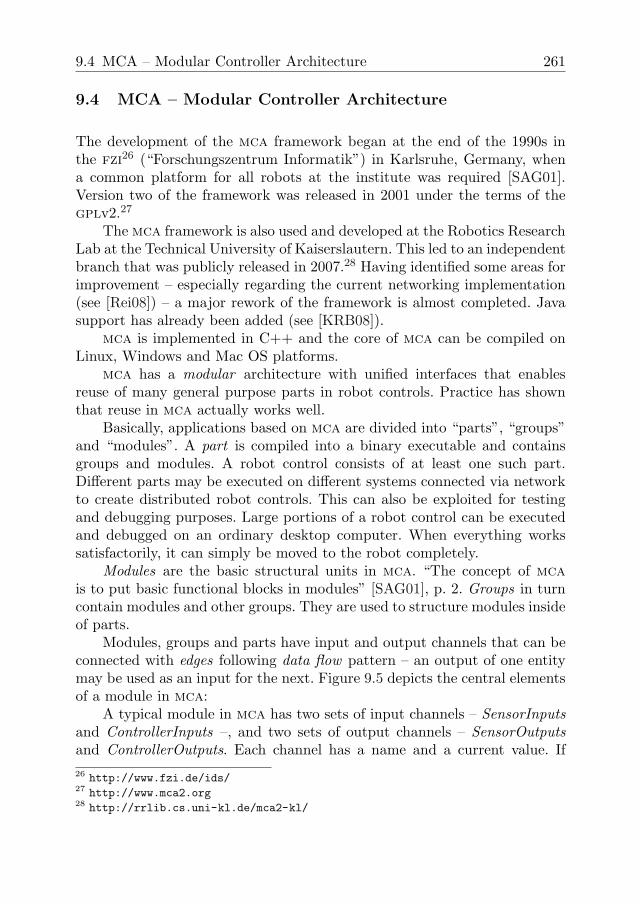
Figure 9.6 shows an example of how parts and modules are connectedon a real robot (screenshots from the MCABrowser tool).
Figure 9.6 Connected mca parts (top) and mca modules inside a group (bottom)

264 9 Software frameworks
Classically, robot controls in mca have a hierarchical structure withgroups and modules interacting directly with hardware on the lowest leveland more abstract modules on higher levels. Nevertheless, it is also possibleto implement robot controls with a flat hierarchy in mca without problems.
The core of the mca framework is rather compact, containing only theessential classes for building applications, as well as some tools. It can beextended with mca libraries that seamlessly integrate into the framework. Bynow, there is a repository with a large set of libraries that provide modules,groups, hardware support and tool extensions for a wide range of applicationareas – for example, facilities for mapping, speech synthesis or computervision. A considerable range of hardware can be accessed using mca.
mca was implemented with a focus on efficiency, which is of centralimportance on robots with tightly limited computing resources. In manyplaces, optimized data structures and shared memory are used to keep thecpu load low.
On platforms running a Real-Time Linux kernel (rtai and rt-Linux),mca is generally capable of meeting hard real-time requirements. However,this requires that all the libraries which are used also provide hard real-timeguarantees. Many libraries do not. Thus, only parts of the framework aresuited for real-time requirements. Apart from that, the blackboard mecha-nism is only suitable for implementations with real-time requirements whenused very carefully.
9.5 Summary and comparison of robotic frameworks
As mentioned in the introduction, there is currently no framework that isclearly superior compared to the others.
Player is popular and easy to use. It provides a convenient api to awide range of robots. Since “Player seeks to constrain controller design aslittle as possible” [GVH03], p. 1, however, it hardly provides any facilitiesfor controller design. For complex robotic applications, it is arguably recom-mendable to use another framework on top of Player as [GCM04] have done.The Player Project is actually used in several other frameworks for accessinghardware including Orca, marie and Pyro.
Microsoft Robotics Developer Studio is designed to be easy to use andprovides powerful tools. Since it is based on .net, any programming lan-guage supported by the .net framework can be used to implement roboticapplications. However, creating applications with Robotics Developer Stu-dio at some stage requires understanding its service-oriented architecture as

9.5 Summary and comparison of robotic frameworks 265
well as xml, which is arguably hard for novices – compared to using Player,for instance. [Bai07], p. 5 backs this observation: “Generally speaking, sev-eral users have reported that MRS remains relatively complex to master forthe moment”. Regarding efficiency, the xml-based encoding used in the net-working mechanism (dssp) is not a good choice, since data encoded in xmlis much larger than the same data encoded in a binary format. Apart fromthat, applications developed with Robotics Developer Studio are limited toWindows platforms.
Orca focuses on bringing Component-Based Software Engineering to theRobotics domain. Looking at the author’s targets, it appears to be an excel-lent approach without any major shortcomings. Notably, significant parts ofOrca depend on the ice middleware. Therefore, ice has a major impact onOrca’s performance as well as other critical aspects discussed in the introduc-tion. If maximum efficiency or real-time capabilities are required, the authorsrecommend implementing all relevant functionality in a single component.There is no support from the framework here.
mca is one of only very few robotic frameworks with support for hardreal-time requirements and it is certainly suitable for large projects. However,the current implementation has a few shortcomings such as the completelysynchronous communication mechanism and complex installation and use.A major rework will address these weaknesses and introduce many new fea-tures. Experimental versions of this already exist (see [Rei08]).

266 9 Software frameworks
Fram
ewor
ks fo
r Rob
otic
Sys
tem
sFr
amew
ork
MC
APl
ayer
Pro
ject
Mic
roso
ft R
obot
ics
Dev
elop
er S
tudi
o(O
rigin
al) D
evel
oper
Mic
roso
ft C
orp.
Lice
nse
GP
L (v
ersi
on 2
or l
ater
)G
PL
(ver
sion
2.1
or l
ater
) or L
GP
L (e
xcep
t of d
river
s)LG
PL
and
GP
L
Hom
epag
eht
tp://
ww
w.m
ca2.
org/
Dev
elop
men
t Per
iod
sinc
e 19
98si
nce
1999
sinc
e 20
04si
nce
2001
Firs
t pub
lic re
leas
e20
0120
0120
06Pl
atfo
rmO
pera
ting
Sys
tem
sLi
nux,
(Win
dow
s, M
ac O
S)
Linu
x, S
olar
is, *
BS
D, M
ac O
SX
Linu
x, (Q
NX
, Win
dow
s X
P, M
ac O
SX
)
Har
dwar
ean
y su
ited
for a
bove
OS
Gen
eral
Arc
hite
ctur
esi
mpl
e, m
odul
ar, s
erve
r/clie
ntm
odul
ar, s
ervi
ce-o
rient
ed -
sim
ilar t
o w
eb s
ervi
ces
com
pone
nt-b
ased
, min
imal
cor
e
Stru
ctur
al e
lem
ents
“par
ts”,
“gro
ups”
, “m
odul
es”
“pla
yer s
erve
rs”,
“clie
nts”
, “(v
irtua
l) de
vice
s”D
ecen
traliz
ed S
yste
m S
ervi
ces
(DS
S),
DS
S N
odes
com
pone
nts
Run
time
Mod
elcl
ient
s re
ceiv
e da
ta p
erio
dica
llyev
ent-d
riven
Inte
rface
type
sets
of p
orts
or p
ins
with
num
bers
Rea
l-tim
e ca
pabi
litie
sha
rd re
al-ti
me
in s
ome
parts
of t
he fr
amew
ork
no h
ard
real
-tim
eno
real
-tim
e in
ter-
serv
ice
com
mun
icat
ion
no re
al-ti
me
inte
r-co
mpo
nent
com
mun
icat
ion
Inte
rope
rabi
lity
-w
ith P
laye
r Pro
ject
(for
har
dwar
e ac
cess
)D
evel
opm
ent
C++
C++
C++
Sup
porte
d la
ngua
ges
C++
, Jav
a, P
ytho
n, P
HP
, C#,
Vis
ual B
asic
, Rub
y
Bui
ld to
olm
ake
Effi
cien
t sha
red
mem
ory
mec
hani
sm fo
r dat
aye
s –
how
ever
, con
curr
ent a
cces
s ca
n bl
ock*
insi
de P
laye
r ser
ver
noas
far a
s pr
ovid
ed b
y IC
E(S
I) un
itsco
nven
tions
: dis
tanc
e in
met
res,
ang
les
in ra
dian
sno
exp
licit
conv
entio
ns (t
o ou
r kno
wle
dge)
conv
entio
ns: d
ista
nce
in m
etre
s, a
ngle
s in
radi
ans
Com
mun
icat
ion
Mec
hani
sm e
xcha
ngea
ble
no*
yes
nono
Sta
ndar
d pr
otoc
olcu
stom
, bas
ed o
n TC
P (m
ore
than
80
com
man
ds)*
cust
om, s
impl
e, b
ased
on
TCP
Dat
a en
codi
ngX
DR
XM
Lst
anda
rd IC
E e
ncod
ing
Asy
nchr
onou
sno
*ye
sye
sye
sP
ull s
trate
gy /
push
stra
tegy
Com
pres
sion
-*-
-A
utom
atic
reso
urce
dis
cove
ryno
*no
not r
eally
Web
inte
rface
no*
noye
s, fo
r adm
inis
tratio
n &
dia
gnos
isno
Sec
urity
pass
wor
d au
then
ticat
ion
none
NTL
M a
uthe
ntic
atio
n, p
olic
ies/
perm
issi
ons
firew
all,
data
enc
rypt
ion
Tool
sG
UI E
dito
r?
Tool
sup
port
incl
udes
Deb
uggi
ng/D
iagn
osis
, Sim
ulat
ion
(3D
)D
ebug
ging
/Dia
gnos
is, S
imul
atio
n (2
D &
3D
)D
ebug
ging
/Dia
gnos
is
* ad
dres
sed
in m
ajor
rew
ork
Orc
aF o
rsch
u ngs
zent
rum
Info
rmat
ik (F
ZI),
Kar
lsru
heR
obot
ics
Res
earc
h La
b, U
nive
rsity
of S
outh
ern
Cal
iforn
ia (U
SC
)A
CFR
, Uni
vers
ity o
f Syd
ney,
Aus
tralia
; CA
S,
Kun
glig
a Te
knis
ka H
ögsk
olan
, Sto
ckho
lm;
Sta
ndar
d E
ditio
n (4
99$)
, Aca
dem
ic E
ditio
n, E
xpre
ss
Edi
tion
http
://pl
ayer
stag
e.so
urce
forg
e.ne
t/ht
tp://
ww
w.m
icro
soft.
com
/robo
tics/
http
://or
ca-r
obot
ics.
sour
cefo
rge.
net/
2004
(as
“Orc
a”)
Win
dow
s X
P, V
ista
, Ser
ver 2
003,
XP
Em
bedd
ed C
E
6.0
and
Mob
ile 6
.0an
y su
ited
for a
bove
OS
– on
ly u
sed
on x
86;
netw
orki
ng re
quire
s pl
atfo
rms
with
sam
e C
stru
ct
layo
ut
any
suite
d fo
r abo
ve O
S, i
nclu
ding
x86
, x64
, AR
M,
PP
C, S
parc
any
suite
d fo
r abo
ve O
S, i
nclu
ding
x86
, x64
, AR
M,
MIP
S, S
uper
H
mod
ular
, dat
aflo
w-o
rient
ed, b
lack
boar
ds
loop
-bas
ed, o
ne m
ain
loop
thre
ad p
er p
art,
thre
ad-
cont
aine
rs fo
r fur
ther
thre
ads*
typi
cally
loop
s in
side
com
pone
nts,
at l
east
one
th
read
per
com
pone
ntob
ject
-orie
nted
/ R
PC
s, s
et o
f sta
ndar
d in
terfa
ces
obje
ct-o
rient
ed /
RP
Cs,
set
of s
tand
ard
inte
rface
sob
ject
-orie
nted
/ R
PC
s, s
et o
f sta
ndar
d in
terfa
ces
(HTT
P in
terfa
ce w
ith J
avaM
CA
)*us
ed in
Orc
a, M
arie
and
Pyr
o
Impl
emen
tion
lang
uage
limite
d in
form
atio
n; d
efin
itely
C#
and
C++
, may
be
othe
rsC
++ (J
ava
with
Jav
aMC
A)*
clie
nt li
brar
ies
for C
, C++
, Pyt
hon,
Jav
a, R
uby,
Gui
le,
Oct
ave,
LIS
P, A
da a
nd M
atla
bA
ll C
LI la
ngua
ges
incl
udin
g C
++, C
#, V
B.N
ET,
Iro
nPyt
hon;
Mic
roso
ft V
isua
l Pro
gram
min
g La
ngua
ge
(VP
L); T
hird
par
ty la
ngua
ges
SCon
s.N
ET
IDE
or M
SB
uild
CM
ake
no e
xplic
it co
nven
tions
, sup
port
in s
ome
blac
kboa
rd
type
s*
DS
SP
: “si
mpl
e”, b
ased
on
SO
AP
; HTT
P fo
r web
br
owse
rsba
sed
on IC
E m
iddl
ewar
e
raw
C s
truct
s*
/ - *
/ /
/
via
UP
nP
(.NE
T ID
E)
Vis
ual P
rogr
amm
ing
Lang
uage
IDE
, adv
ance
d S
imul
atio
n (3
D),
Test
ing
Figure 9.7 Tabular comparison of presented frameworks (June 2009)