Embed Size (px)
Citation preview
ArduACRO Custom ArduACRO flight mode programmed in ArduPlane to implement autonomous roll algorithm Custom MATLAB/MAVLink interface for communication and telemetry 3-axis gyros and accelerometers Barometric Altimeter/Airspeed and 5Hz GPS Atmel ATMEGA Processor 915MHz telemetry downlink
A slow roll is one of 3 fundamental maneuvers 360° roll with or without hesitations along the longitudinal axis while level, climbing, or descending
Eric Sandifer 1,150 hours total time Earned license in 2002, started
flying aerobatics 2003 Flown in all IAC categories,
currently flying Unlimited in the Pitts, 1St place wins in all categories, 2015 Northeast Series Advanced Champion
President of IAC Club 19 and was contest director at 7 contests
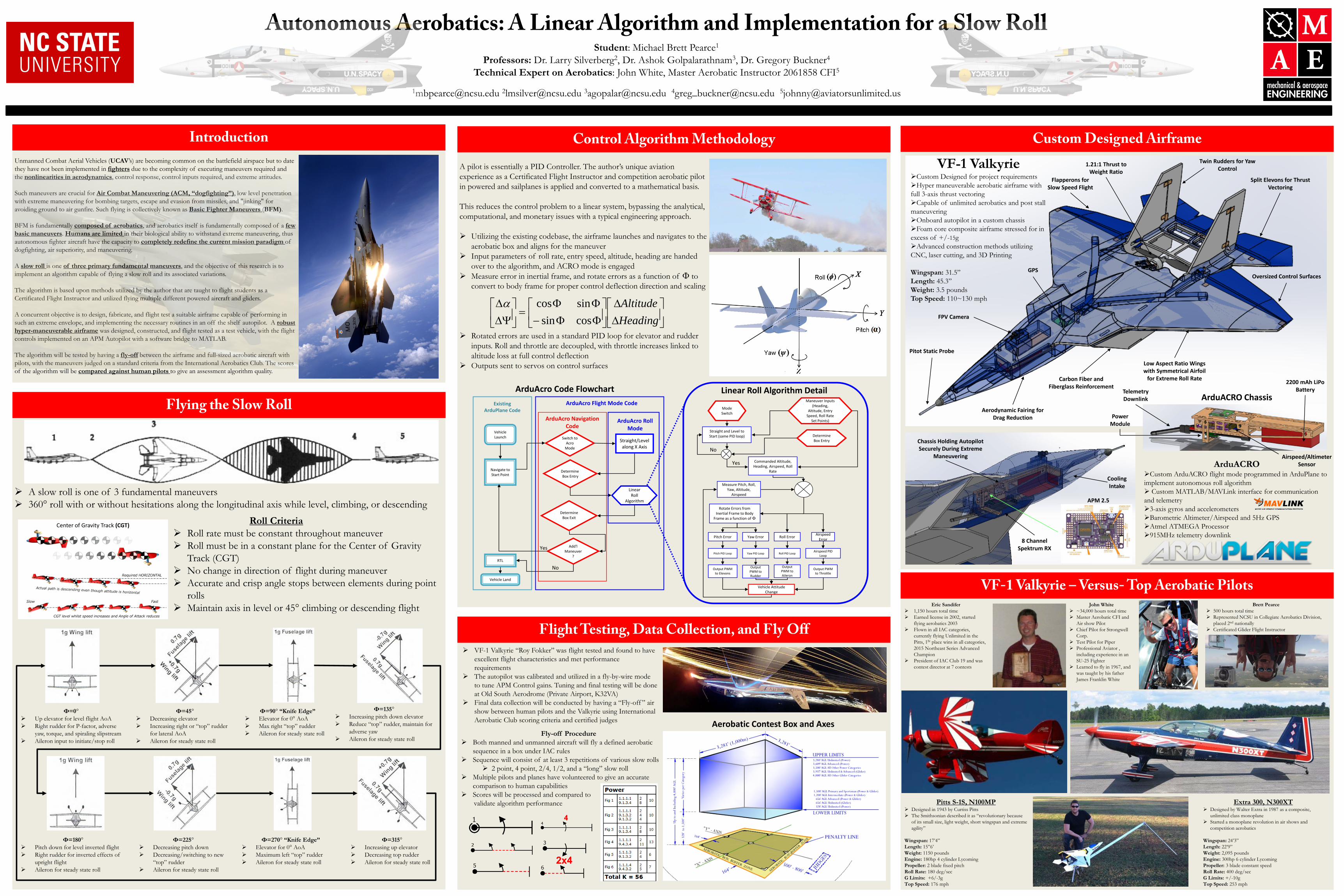
Autonomous Aerobatics: A Linear Algorithm and Implementation for a Slow Roll Student: Michael Brett Pearce1
Professors: Dr. Larry Silverberg2, Dr. Ashok Golpalarathnam3, Dr. Gregory Buckner4 Technical Expert on Aerobatics: John White, Master Aerobatic Instructor 2061858 CFI5
[email protected] [email protected] [email protected] [email protected] [email protected]
Unmanned Combat Aerial Vehicles (UCAV’s) are becoming common on the battlefield airspace but to date they have not been implemented in fighters due to the complexity of executing maneuvers required and the nonlinearities in aerodynamics, control response, control inputs required, and extreme attitudes. Such maneuvers are crucial for Air Combat Maneuvering (ACM, “dogfighting”), low level penetration with extreme maneuvering for bombing targets, escape and evasion from missiles, and "jinking" for avoiding ground to air gunfire. Such flying is collectively known as Basic Fighter Maneuvers (BFM). BFM is fundamentally composed of aerobatics, and aerobatics itself is fundamentally composed of a few basic maneuvers. Humans are limited in their biological ability to withstand extreme maneuvering, thus autonomous fighter aircraft have the capacity to completely redefine the current mission paradigm of dogfighting, air superiority, and maneuvering. A slow roll is one of three primary fundamental maneuvers, and the objective of this research is to implement an algorithm capable of flying a slow roll and its associated variations. The algorithm is based upon methods utilized by the author that are taught to flight students as a Certificated Flight Instructor and utilized flying multiple different powered aircraft and gliders. A concurrent objective is to design, fabricate, and flight test a suitable airframe capable of performing in such an extreme envelope, and implementing the necessary routines in an off the shelf autopilot. A robust hyper-maneuverable airframe was designed, constructed, and flight tested as a test vehicle, with the flight controls implemented on an APM Autopilot with a software bridge to MATLAB. The algorithm will be tested by having a fly-off between the airframe and full-sized aerobatic aircraft with pilots, with the maneuvers judged on a standard criteria from the International Aerobatics Club. The scores of the algorithm will be compared against human pilots to give an assessment algorithm quality.
Introduction
Flying the Slow Roll
Control Algorithm Methodology
Flight Testing, Data Collection, and Fly Off
Custom Designed Airframe
John White ~34,000 hours total time Master Aerobatic CFI and
Air show Pilot Chief Pilot for Strongwell
Corp. Test Pilot for Piper Professional Aviator ,
including experience in an SU-25 Fighter
Learned to fly in 1967, and was taught by his father James Franklin White
Brett Pearce 500 hours total time Represented NCSU in Collegiate Aerobatics Division,
placed 2nd nationally Certificated Glider Flight Instructor
ArduAcro Navigation Code
Vehicle Launch
Navigate to Start Point
Switch to Acro
Mode
Straight/Level along X Axis
Determine Box Entry
Linear Roll
Algorithm
Determine Box Exit
Add'l Maneuver
? RTL
Vehicle Land
Yes
No
Existing ArduPlane Code
ArduAcro Flight Mode Code
ArduAcro Roll Mode
ArduAcro Code Flowchart
Mode Switch
Maneuver Inputs (Heading,
Altitude, Entry Speed, Roll Rate
Set Points)
Determine Box Entry
Straight and Level to Start (same PID loop)
Measure Pitch, Roll, Yaw, Altitude,
Airspeed
Rotate Errors from Inertial Frame to Body
Frame as a function of Φ
Vehicle Attitude Change
Output PWM to Throttle
Output PWM to Aileron
Output PWM to Rudder
Output PWM to Elevons
Pitch PID Loop Yaw PID Loop Roll PID Loop Airspeed PID Loop
Airspeed Error Roll Error Yaw Error Pitch Error
Commanded Altitude, Heading, Airspeed, Roll
Rate
Yes
No
Linear Roll Algorithm Detail
Roll Criteria Roll rate must be constant throughout maneuver Roll must be in a constant plane for the Center of Gravity
Track (CGT) No change in direction of flight during maneuver Accurate and crisp angle stops between elements during point
rolls Maintain axis in level or 45° climbing or descending flight
VF-1 Valkyrie “Roy Fokker” was flight tested and found to have excellent flight characteristics and met performance requirements
The autopilot was calibrated and utilized in a fly-by-wire mode to tune APM Control gains. Tuning and final testing will be done at Old South Aerodrome (Private Airport, K32VA)
Final data collection will be conducted by having a “Fly-off ” air show between human pilots and the Valkyrie using International Aerobatic Club scoring criteria and certified judges
Φ=0° Up elevator for level flight AoA Right rudder for P-factor, adverse
yaw, torque, and spiraling slipstream Aileron input to initiate/stop roll
Φ=45° Decreasing elevator Increasing right or “top” rudder
for lateral AoA Aileron for steady state roll
Φ=90° “Knife Edge” Elevator for 0° AoA Max right “top” rudder Aileron for steady state roll
Φ=135° Increasing pitch down elevator Reduce “top” rudder, maintain for
adverse yaw Aileron for steady state roll
Φ=180° Pitch down for level inverted flight Right rudder for inverted effects of
upright flight Aileron for steady state roll
Φ=225° Decreasing pitch down Decreasing/switching to new
“top” rudder Aileron for steady state roll
Φ=270° “Knife Edge” Elevator for 0° AoA Maximum left “top” rudder Aileron for steady state roll
Φ=315° Increasing up elevator Decreasing top rudder Aileron for steady state roll
∆∆
ΦΦ−ΦΦ
=
∆Ψ∆
HeadingAltitude
cossinsincosα
VF-1 Valkyrie Custom Designed for project requirements Hyper maneuverable aerobatic airframe with full 3-axis thrust vectoring Capable of unlimited aerobatics and post stall maneuvering Onboard autopilot in a custom chassis Foam core composite airframe stressed for in excess of +/-15g Advanced construction methods utilizing CNC, laser cutting, and 3D Printing Wingspan: 31.5” Length: 45.3” Weight: 3.5 pounds Top Speed: 110~130 mph
VF-1 Valkyrie – Versus- Top Aerobatic Pilots
Fly-off Procedure Both manned and unmanned aircraft will fly a defined aerobatic
sequence in a box under IAC rules Sequence will consist of at least 3 repetitions of various slow rolls
2 point, 4 point, 2/4, 1/2, and a “long” slow roll Multiple pilots and planes have volunteered to give an accurate
comparison to human capabilities Scores will be processed and compared to validate algorithm performance Extra 300, N300XT
Designed by Walter Extra in 1987 as a composite, unlimited class monoplane
Started a monoplane revolution in air shows and competition aerobatics
Wingspan: 24’3” Length: 22’9” Weight: 2,095 pounds Engine: 300hp 6 cylinder Lycoming Propeller: 3 blade constant speed Roll Rate: 400 deg/sec G Limits: +/-10g Top Speed: 253 mph
Aerobatic Contest Box and Axes
A pilot is essentially a PID Controller. The author’s unique aviation experience as a Certificated Flight Instructor and competition aerobatic pilot in powered and sailplanes is applied and converted to a mathematical basis. This reduces the control problem to a linear system, bypassing the analytical, computational, and monetary issues with a typical engineering approach. Utilizing the existing codebase, the airframe launches and navigates to the
aerobatic box and aligns for the maneuver Input parameters of roll rate, entry speed, altitude, heading are handed
over to the algorithm, and ACRO mode is engaged Measure error in inertial frame, and rotate errors as a function of Φ to
convert to body frame for proper control deflection direction and scaling
Rotated errors are used in a standard PID loop for elevator and rudder
inputs. Roll and throttle are decoupled, with throttle increases linked to altitude loss at full control deflection
Outputs sent to servos on control surfaces
ArduACRO Chassis
Pitts S-1S, N100MP Designed in 1943 by Curtiss Pitts The Smithsonian described it as “revolutionary because
of its small size, light weight, short wingspan and extreme agility”
Wingspan: 17’4” Length: 15”6’ Weight: 1150 pounds Engine: 180hp 4 cylinder Lycoming Propeller: 2 blade fixed pitch Roll Rate: 180 deg/sec G Limits: +6/-3g Top Speed: 176 mph
Oversized Control Surfaces
Split Elevons for Thrust Vectoring
1.21:1 Thrust to Weight Ratio
Low Aspect Ratio Wings with Symmetrical Airfoil
for Extreme Roll Rate
Chassis Holding Autopilot Securely During Extreme
Maneuvering
FPV Camera
Pitot Static Probe
GPS
Aerodynamic Fairing for Drag Reduction
2200 mAh LiPo Battery Telemetry
Downlink
Airspeed/Altimeter Sensor
APM 2.5
Carbon Fiber and Fiberglass Reinforcement
Power Module
Twin Rudders for Yaw Control
8 Channel Spektrum RX
Cooling Intake
Flapperons for Slow Speed Flight
Center of Gravity Track (CGT)