Embed Size (px)
Citation preview
A L M A M AT E R S T U D I O R U M - U N I V E R S I TÀ D IB O LO G N A
department of computer science and engineering
Dottorato di ricerca ininformaticaCiclo X X V I I I
Settore concorsuale di afferenza 0 9 / H 1Settore scientifico disciplinare I N G - I N F / 0 5
A U TO N O M I C M A N A G E M E N T O F C LO U DV I R T U A L I N F R A S T R U C T U R E S
Presentata da: Relatore:daniela loreti prof.ssa anna ciampolini
Coordinatore dottorato:prof. paolo ciaccia
Esame finale anno 2 0 1 6


Daniela Loreti: Autonomic management of cloud virtual infrastruc-tures , © 2016.
website:https://www.unibo.it/sitoweb/daniela.loreti/
e-mail:[email protected]

A B S T R A C T
The new model of interaction suggested by Cloud Comput-ing has experienced a significant diffusion over the last yearsthanks to its capability of providing customers with the illu-sion of an infinite amount of reliable resources. Nevertheless,the challenge of efficiently manage a large collection of virtualcomputing nodes has just been partially moved from the cus-tomer’s private datacenter to the larger provider’s infrastruc-ture that we generally address as “the cloud”. A lot of effort – inboth academic and industrial field – is therefore concentratedon policies for the efficient and autonomous management ofvirtual infrastructures.
The research on this topic is further encouraged by the dif-fusion of cheap and portable sensors and the availability of al-most ubiquitous Internet connectivity that are constantly creat-ing large flows of information about the environment we live in.The need for fast and reliable mechanisms to process these con-siderable volumes of data has inevitably pushed the evolutionfrom the initial scenario of a single (private or public) cloudtowards cloud interoperability, giving birth to several forms ofcollaboration between clouds. The efficient resource manage-ment is further complicated in these heterogeneous environ-ments, making autonomous administration more and more de-sirable.
In this thesis, we initially focus on the challenges of auto-nomic management in a single-cloud scenario, considering thebenefits and shortcomings of centralized and distributed solu-tions and proposing an original decentralized model. Later inthis dissertation, we face the challenge of autonomic manage-ment in large interconnected cloud environments, where themovement of virtual resources across the infrastructure nodesis further complicated by the intrinsic heterogeneity of the sce-nario and difficulties introduced by the higher latency mediumbetween datacenters. According to that, we focus on the costmodel for the execution of distributed data-intensive applica-tion on multiple clouds and we propose different managementpolicies leveraging cloud interoperability.
v

P U B L I C AT I O N S
Parts of the work in this thesis have previously appeared in the
following publications:
[1] D. Loreti, A. Ciampolini, F. Chesani, and P. Mello, “Pro-cess mining monitoring for map reduce applications in thecloud,” in CLOSER, 6th International Conference on CloudComputing and Services Science, 2016.
[2] D. Loreti and A. Ciampolini, “Mapreduce over the hybridcloud: a novel infrastructure management policy,” in Pro-ceedings of the 8th IEEE/ACM International Conference on Util-ity and Cloud Computing (UCC), 2015.
[3] F. J. Clemente-Castellò, B. Nicolae, K. Katrinis, M. M.Rafique, R. Mayo, J. C. Fernàndez, and D. Loreti, “Enablingbig data analytics in the hybrid cloud using iterative mapre-duce,” in Proceedings of the 8th IEEE/ACM International Con-ference on Utility and Cloud Computing (UCC), 2015.
[4] D. Loreti and A. Ciampolini, “A hybrid cloud infrastructurefor big data applications,” in Proceedings of the 17th Interna-tional Conferences on High Performance Computing and Com-munications, IEEE, 2015.
[5] D. Loreti and A. Ciampolini, “Shyam: a system for auto-nomic management of virtual clusters in hybrid clouds,”in 1st Workshop on Federated Cloud Networking (FedCloudNet),Springer, 2015.
[6] D. Loreti and A. Ciampolini, “A distributed self-balancingpolicy for virtual machine management in cloud datacen-ters,” in High Performance Computing Simulation (HPCS),2014 International Conference on, pp. 391–398, July 2014.
[7] D. Loreti and A. Ciampolini, “A decentralized approach forvirtual infrastructure management in cloud datacenters,”International Journal On Advances in Intelligent Systems, vol. 7,pp. 507–518, December 2014.
vii
[8] D. Loreti and A. Ciampolini, “Policy for distributed self-organizing infrastructure management in cloud datacen-ters,” in ICAS 2014, The Tenth International Conference on Au-tonomic and Autonomous Systems, pp. 37–43, April 2014.
A W A R D S
The work “Policy for Distributed Self-Organizing Infrastruc-ture Management in Cloud Datacenters” was awarded with aBest Paper Award price after the presentation at ICAS 2014, theTenth International Conference on Autonomic and AutonomousSystems, held in Chamonix, France on April 20 - 24, 2014.
viii
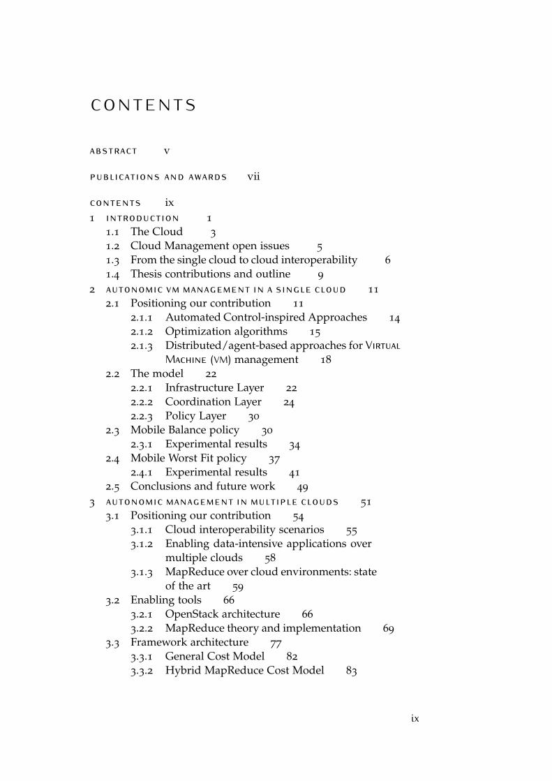
C O N T E N T S
abstract v
publications and awards vii
contents ix1 introduction 1
1.1 The Cloud 3
1.2 Cloud Management open issues 5
1.3 From the single cloud to cloud interoperability 6
1.4 Thesis contributions and outline 9
2 autonomic vm management in a single cloud 11
2.1 Positioning our contribution 11
2.1.1 Automated Control-inspired Approaches 14
2.1.2 Optimization algorithms 15
2.1.3 Distributed/agent-based approaches for VirtualMachine (VM) management 18
2.2 The model 22
2.2.1 Infrastructure Layer 22
2.2.2 Coordination Layer 24
2.2.3 Policy Layer 30
2.3 Mobile Balance policy 30
2.3.1 Experimental results 34
2.4 Mobile Worst Fit policy 37
2.4.1 Experimental results 41
2.5 Conclusions and future work 49
3 autonomic management in multiple clouds 51
3.1 Positioning our contribution 54
3.1.1 Cloud interoperability scenarios 55
3.1.2 Enabling data-intensive applications overmultiple clouds 58
3.1.3 MapReduce over cloud environments: stateof the art 59
3.2 Enabling tools 66
3.2.1 OpenStack architecture 66
3.2.2 MapReduce theory and implementation 69
3.3 Framework architecture 77
3.3.1 General Cost Model 82
3.3.2 Hybrid MapReduce Cost Model 83
ix
x Contents
3.3.3 Implementation details 85
3.3.4 Experimental Results 86
3.3.5 Discussion 89
3.4 The SPAN policy 91
3.4.1 Experimental results 94
3.4.2 Discussion 96
3.5 The HyMR policy 97
3.5.1 Experimental results 100
3.5.2 Discussion 104
3.6 Iterative Map Reduce over the hybrid cloud 105
3.6.1 Challenges of data locality in hybrid Infrastructureas a Service (IaaS) clouds 106
3.6.2 Asynchronous data rebalancing technique 107
3.6.3 Performance prediction model 109
3.6.4 Evaluation 113
3.6.5 Discussion 123
3.7 Conclusions and future work 124
4 monitoring the architecture with process min-ing 127
4.1 Positioning our contribution 130
4.2 MapReduce Auto-scaling Engine 131
4.2.1 Monitoring the system execution w.r.t.declarative constraints 132
4.3 Use Case Scenario 134
4.3.1 Testbed architecture and data 134
4.3.2 Properties to be monitored 135
4.3.3 The output from the Mobucon monitor 138
4.4 Conclusions and future work 141
5 conclusions and future directions 143
5.1 Summary 143
5.2 Conclusions 144
5.3 Future research directions 145
bibliography 147
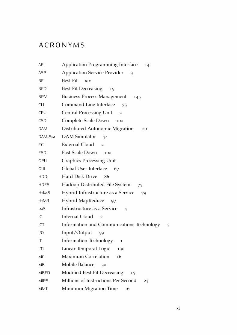
A C R O N Y M S
API Application Programming Interface 14
ASP Application Service Provider 3
BF Best Fit xiv
BFD Best Fit Decreasing 15
BPM Business Process Management 145
CLI Command Line Interface 75
CPU Central Processing Unit 3
CSD Complete Scale Down 100
DAM Distributed Autonomic Migration 20
DAM-Sim DAM Simulator 34
EC External Cloud 2
FSD Fast Scale Down 100
GPU Graphics Processing Unit
GUI Global User Interface 67
HDD Hard Disk Drive 86
HDFS Hadoop Distributed File System 75
HyIaaS Hybrid Infrastructure as a Service 79
HyMR Hybrid MapReduce 97
IaaS Infrastructure as a Service 4
IC Internal Cloud 2
ICT Information and Communications Technology 3
I/O Input/Output 59
IT Information Technology 1
LTL Linear Temporal Logic 130
MC Maximum Correlation 16
MB Mobile Balance 30
MBFD Modified Best Fit Decreasing 15
MIPS Millions of Instructions Per Second 23
MMT Minimum Migration Time 16
xi
xii Contents
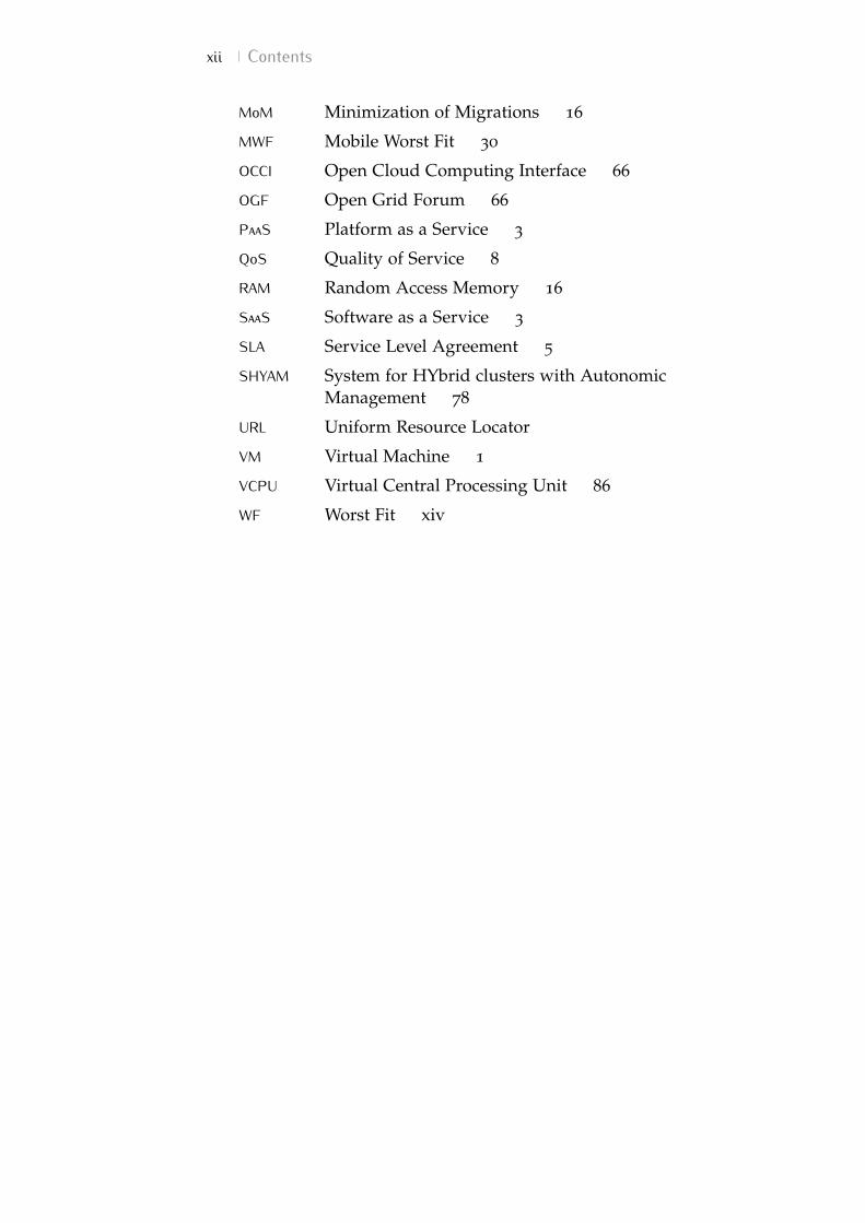
MoM Minimization of Migrations 16
MWF Mobile Worst Fit 30
OCCI Open Cloud Computing Interface 66
OGF Open Grid Forum 66
PaaS Platform as a Service 3
QoS Quality of Service 8
RAM Random Access Memory 16
SaaS Software as a Service 3
SLA Service Level Agreement 5
SHYAM System for HYbrid clusters with AutonomicManagement 78
URL Uniform Resource Locator
VM Virtual Machine 1
VCPU Virtual Central Processing Unit 86
WF Worst Fit xiv
L I S T O F F I G U R E S
Figure 1.1 The cloud paradigm involves different kindsof users, providing them with software,development platforms or infrastructuralresources according to their needs. 4
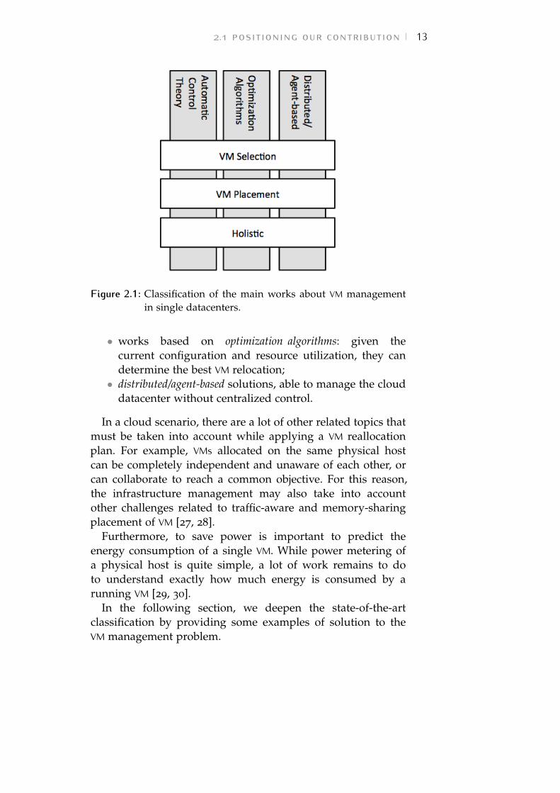
Figure 2.1 Classification of the main works aboutVM management in single datacenters. 13
Figure 2.2 The three tiers architecture. The separa-tion between layers ensures the possibil-ity to test different policies and protocolswith the same infrastructure implemen-tation. 22
Figure 2.3 Example of "knows the neighbor" relationapplied on a collection of physical nodes.The relation is not symmetric, thus if node"a knows the neighbor b", this means that bis included in the neighborhood of a but,in general, a is not in the neighborhoodof b. 24
Figure 2.4 Schema of two overlapping neighborhoods.The VM descriptor vmi is exchanged acrossphysical hosts, crossing the neighborhoodboundaries, until the nodes agree witha common reallocation plan i.e., a "sta-ble" allocation hypothesis for vmi is de-tected. 25
Figure 2.5 Example of protocol interaction rounds.Node N2 is shared by nodes N1 and N3.Therefore, their MasterClients must coor-dinate to ensure the consistency of statusinformation. 29
Figure 2.6 Example of three overlapping neighbor-hoods. 34
Figure 2.7 Distribution of servers on load intervals. 34
xiii
xiv List of Figures
Figure 2.8 Mobile Balance (MB) and Worst Fit (WF)-GLO performance comparison. 2.8a: Num-ber of migration performed for increas-ing number of simulated hosts. We com-pare the performance of MB with toler-ance interval 10.0 with centralized WF-GLO. 2.8b: Maximum number of mes-sages exchanged (sent and received) bya single host of the datacenter. MB sig-nificantly outperforms WF-GLO for highvalues of simulated hosts. 35
Figure 2.9 Mobile Worst Fit (MWF) end Best Fit(BF) performance comparison for variousvalues of average load on each physicalserver (LOAD% on the x-axis). 42
Figure 2.10 Distribution of servers on load intervals.In the initial scenario (INI) all the servershave 50% load except for 20 underloadedand 20 overloaded nodes. 43
Figure 2.11 Distribution of servers on load intervals.In the initial scenario (INI) all the serversare on average loaded around the valueof FTH_UP. 45
Figure 2.12 MWF power saving performance test. Thenumber m of working servers at the endof different MWF executions is comparedto the minimum possible number Mopt
of running servers in each scenario. Theexperiments are repeated with differentvalues of the ratio q/t. 47
Figure 2.13 MWF and WF-GLO performance compar-ison. 2.13a: Number of migrations per-formed for increasing number of simu-lated hosts. We compare the performanceof MWF with tolerance interval 10.0 withcentralized WF-GLO. 2.13b: Maximum num-ber of messages exchanged (sent and re-ceived) by a single host of the datacenter.MWF significantly outperforms WF-GLOfor high values of simulated hosts. 48
Figure 3.1 Multi-cloud scenarios. 51
List of Figures xv
Figure 3.2 Classification of interoperability solutionsfor clouds as suggested in the work byToosi et al [1]. This dissertation mainlyfocus on solutions to enable the hybridcloud scenario in grey. 56
Figure 3.3 Schema of main OpenStack modules in-teractions [2]. 67
Figure 3.4 Execution of a generic MapReduce appli-cation. The map and reduce tasks can bedistributed on different computing nodes. 70
Figure 3.5 Execution schema of a word count ap-plication implemented according to theMapReduce model. 71
Figure 3.6 Example of task deployment over a four-node architecture for a word count appli-cation. The allocation of the tasks is con-trolled by a coordinator process. The in-put dataset is partitioned across the nodesand each map task is responsible for theexecution over a particular subset of theinput (Figure 3.6a). The intermediate pairsare then sent to the reduce tasks (shufflephase) as in Figure 3.6b. Finally the re-ducers process merges the received pairsand emit the output (Figure 3.6c). 72
Figure 3.7 When the execution command is issuedto the Hadoop cluster through the CommandLine Interface (CLI), the JobTracker on themaster node is involved. It interacts withthe Namenode daemon to create a num-ber of map/reduce tasks consistent withthe number of data blocks to be processed.The JobTracker also allocates the taskspreferring a data-local computation. Forexample, the map working on block 001
is likely to sent to machine 2 containingthat block on its portion of Hadoop Dis-tributed File System (HDFS). 76
Figure 3.8 Layer architecture of System for HYbridclusters with Autonomic Management (SHYAM)system. 79
xvi List of Figures
Figure 3.9 Hybrid cloud scenario. SHYAM is an on-premise software component able to col-lect information about the current statusof Internal Cloud (IC) and dynamicallyadd off-premise resources if needed. 80
Figure 3.10 Hybrid Infrastructure as a Service layer.The subcomponents are displayed in grey. 81
Figure 3.11 Performance of Hybrid Infrastructure asa Service (HyIaaS) in a hybrid scenario. 87
Figure 3.12 Comparison of times Te to execute on ICand External Cloud (EC) varying the vol-umes of data D and the number Y of off-premise spawned VMs. 3.12a shows thecase of a limited inter-cloud bandwidth(L=10Mbit/s), while 3.12b illustrates thebehavior with a higher bandwidth (L=100Mbit/s) 90
Figure 3.13 Performance of HyIaaS in a hybrid scenario.Figure 3.11a shows the time to providenew off-premise VMs with different char-acteristics. Figure 3.13a compares the timeto perform a Hadoop word count work-load on a fully on-premise cluster - with(Te_I) or without (Te_I_stress) a stressingcondition on a physical node -, with theperformance on a hybrid cluster createdby the HyIaaS layer. Figure3.13b shows thepercentage gain obtained by our solution. 95
Figure 3.14 Performance of Hybrid MapReduce (HyMR)policy and HyIaaS system with differentMapReduce workloads. 102
Figure 3.15 HyMR gain in execution time for word count,inverted index and tera sort workloads. 103
Figure 3.16 HyMR scale-down performance. 104
Figure 3.17 Hybrid IaaS OpenStack cloud example: onefat node on-premise and two fat nodesoff-premise 115
Figure 3.18 TestDFIO micro-calibration: rebalance progressfor 20 GB total data. 117
List of Figures xvii
Figure 3.19 K-Means of a 20GB dataset. Strong scala-bility: predicted vs. real total completiontime for 10 iterations for a single cloudand a hybrid cloud setup. The measuredcompletion time observed on the singlecloud is the Baseline. Lower is better. 119
Figure 3.20 K-Means of a 20GB dataset. Iteration anal-ysis: completion time per iteration for anincreasing number of off-premise VM in-stances. Lower is better. 119
Figure 3.21 IGrep of a 20GB dataset. Strong scala-bility: predicted vs. real total completiontime for 10 iterations for a single cloudand a hybrid cloud setup. The measuredcompletion time observed on the singlecloud is the Baseline. Lower is better. 122
Figure 3.22 IGrep of a 20GB dataset. Iteration analy-sis: completion time per iteration for anincreasing number of off-premise VM in-stances. Lower is better. 122
Figure 4.1 Framework architecture of MapReduce Auto-scaling Engine 132
Figure 4.2 Declare Response constraint, with a met-ric temporal deadline 136
Figure 4.3 The output of the Mobucon monitor forthe execution of word count job on thegiven testbed. 139
Figure 4.4 Output of the Mobucon monitor subse-quent to Figure 4.3. 140
L I S T O F TA B L E S
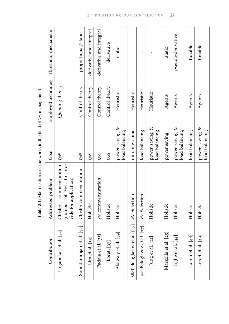
Table 2.1 Main features of the works in the field ofVM management 21
Table 2.2 Values of standard deviation σ of tracesin Figure 2.7 for decreasing values of tol-erance interval t. 37
Table 3.1 Main features of the works in the field ofVM management over multiple-clouds 62
Table 3.2 Main features of the works in the field ofVM management over multiple-clouds 63
Table 3.3 Main features of the works in the field ofVM management over multiple-clouds 64
Table 3.4 Our contributions in the field of VM man-agement over hybrid cloud 65
Table 3.5 Characteristics of the VMs considered forTp evaluation depicted in Figure 3.11a 86
Table 3.6 TestDFSIO Agerage completion time periteration 118
Table 4.1 Some Declare constraints 134
xviii
1 I N T R O D U C T I O N
As the advent of Cloud Computing has suggested a newmodel of interaction between the Information Technology (IT)provider and the customers, the computing infrastructure hasbeen turned into a service that the customer can exploitaccording to her needs after a contract negotiation with theprovider. This paradigm experienced a significant diffusionduring the last few years thanks to its capability of relievingcompanies of the burden of managing their IT infrastructures.At the same time, the demand for scalable yet efficientand energy-saving cloud architectures has made the GreenComputing area stronger, driven by the pressing need for bothgreater computational power and restraint of economical andenvironmental expenditures.
The challenge of efficiently managing a collection ofphysical servers avoiding bottlenecks and power waste, is notcompletely solved by the Cloud Computing paradigm, but itis only partially moved from the customers’s IT infrastructureto the provider’s data centers. Since cloud resources areoften managed and offered to customers through a collectionof Virtual Machines (VMs), a lot of efforts concerning theGreen Computing trend are now concentrating on finding thebest VM allocation to obtain efficiency without compromisingperformances.
Furthermore, Cloud Computing is facing the challenge ofan ever growing complexity due to the increasing number ofusers and their augmenting resource requests. This complexitycan only be managed by providing the cloud infrastructurewith an autonomic behavior, so that, it can autonomouslyallocate and move VMs across the datacenter’s nodes withoutthe human intervention.
Recently, the cloud computing model has seen the evolutionfrom the initial scenario of a public cloud offering its resourcesto customers through virtualization and Internet, towardthe concept of hybrid cloud, where the classic scenario isenriched with a private (company owned) cloud e.g., for themanagement of sensible data. The hybrid cloud paradigm has
1
2 introduction
gained further attraction as the attention to computationallyintensive applications increased. As a relevant example, weconsider the so-called big data scenario.
The trending evolution towards the “Internet of things”and the general increase in broadband are constantly creatinglarge volumes of data that need to be processed for higherintelligence. In this scenario, assuming a limited set ofcomputing resource available on-premise – i.e., in the privateInternal Cloud (IC) –, it is crucial to allow the dynamicprovision of additional computing nodes by relaying on theresource availability of an External Cloud (EC), e.g. a publiccloud.
Similarly to the classic cloud paradigm, the hybrid scenariowould benefit from an autonomous management systemable to dynamically scale-up towards the public cloud whenfurther resources are requested (or scale-down to reduce theinfrastructure costs).
Nevertheless, in a hybrid setup, further issues emerge e.g.,the benefits of accelerating the computation can be mitigated(or even frustrated) by the challenges of data locality anddata movement crossing the on-premise boundaries – which isusually over a higher latency medium, when compared to aco-located servers scenario.
This thesis studies the policies and the mechanisms forautonomic VM management in public and hybrid cloudarchitectures. On one hand, in the context of a singlepublic cloud, we investigate both distributed and centralizedsolutions by reviewing previous state-of-the-art works, andby contributing with our own proposal to decentralize themanagement of the virtual infrastructure.
On the other hand, we highlight the main challenges inthe field of multiple clouds by discussing the details and theintricacies of executing intensive data processing over hybridenvironments. In this regard, we propose our contributionto enable infrastructure scaling and overcome the drawbacksintroduced by the multiple cloud scenario.
In the rest of this chapter, we describe cloud architectures(Chapter 1.1) as well as the issues related to VM management(1.2) and we introduce the multiple cloud scenario in detail(1.3).
1.1 the cloud 3
1.1 the cloudAs Information and Communications Technology (ICT) is gettingmore and more important for business, a growing number ofmodern companies is facing the need for dedicated hardwareand computing infrastructure. Nevertheless, the managementof a datacenter can be too expensive for a small enterprise.Companies can autonomously buy the hardware and softwaretheir business requires but they need the support of anIT provider to firstly install and configure these complexarchitectures. Moreover, the computational requirements of anenterprise can dynamically change as its business grows ordecrease making the continuous intervention by IT providerscrucial to adapt the datacenter structure. The enterprise canalso decide not to relay on external IT companies but hire highqualified personnel to manage the computer infrastructure.However, the costs of all these solutions remain very high.
The effort of many IT companies concerning cloudcomputing is to supply infrastructures that can be completelymanaged in a rather simple way, not only by the provider,but also by nontechnical employees of the customer enterprise.From the cloud customer point of view, since no more specificoperations on hardware and operating systems are necessary,no more high qualified staff is needed to deal with computinginfrastructure issues.
As Cloud Computing rewrite the rules of business modelinvolving IT providers and customers, it is sometimesaddressed as the "fifth generation of computing", because itsrevolution comes after the Mainframe, the personal computer,the client-server model and the web [3]. However, CloudComputing can be seen as a complex service: a set oftechnologies allowing the customer to remotely use hardware– storage, Central Processing Unit (CPU), network, etc. – andsoftware resources owned by the IT provider. As pointed outby [3], there are three fundamental kinds of services related toCloud Computing:
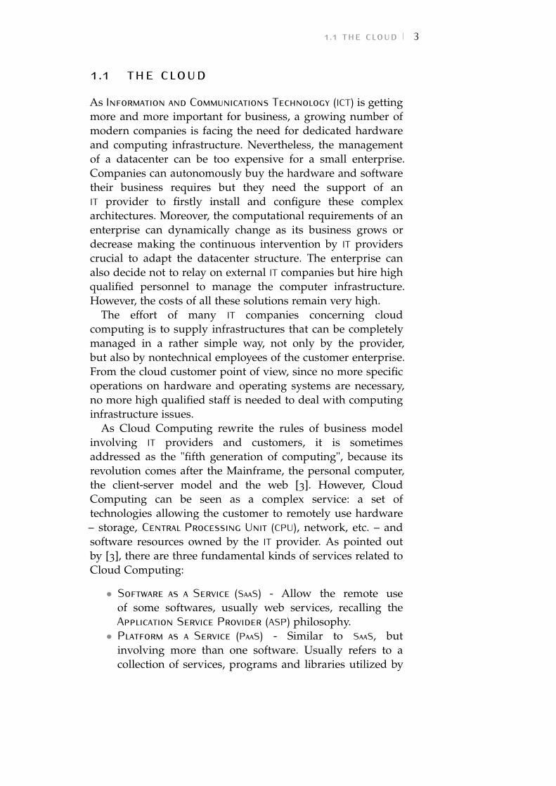
• Software as a Service (SaaS) - Allow the remote useof some softwares, usually web services, recalling theApplication Service Provider (ASP) philosophy.• Platform as a Service (PaaS) - Similar to SaaS, but
involving more than one software. Usually refers to acollection of services, programs and libraries utilized by
4 introduction
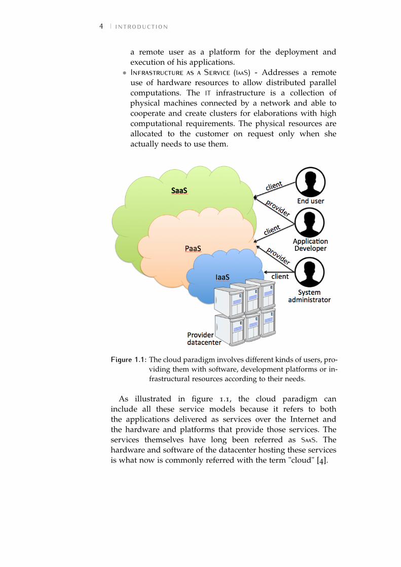
a remote user as a platform for the deployment andexecution of his applications.• Infrastructure as a Service (IaaS) - Addresses a remote
use of hardware resources to allow distributed parallelcomputations. The IT infrastructure is a collection ofphysical machines connected by a network and able tocooperate and create clusters for elaborations with highcomputational requirements. The physical resources areallocated to the customer on request only when sheactually needs to use them.
Figure 1.1: The cloud paradigm involves different kinds of users, pro-viding them with software, development platforms or in-frastructural resources according to their needs.
As illustrated in figure 1.1, the cloud paradigm caninclude all these service models because it refers to boththe applications delivered as services over the Internet andthe hardware and platforms that provide those services. Theservices themselves have long been referred as SaaS. Thehardware and software of the datacenter hosting these servicesis what now is commonly referred with the term "cloud" [4].
1.2 cloud management open issues 5
1.2 cloud management open issuesA cloud datacenter is typically composed of a large number(hundreds or even thousands) of physical servers, hostinga collection of VMs accessed remotely by customers. In thisscenario, a software component (e.g., OpenStack [5], AmazonEC2 [6], Aptana Cloud [7], Aneka Cloud [8], etc.) is responsiblefor the management of the cloud infrastructure, including themigration of VMs and the allocation of physical resources tocustomers.
Through the use of virtualization, multiple VMs can runon a single physical machine. A widespread practice in thisscenario is to allocate the VMs on a machine such that thetotal amount of virtual resources requested never exceeds thephysical resources available. Nevertheless, since the resourcerequirements of the applications running on the VM arehighly dynamic, such a static allocation of resources can stilllead to a significant resource underutilization. To addressthis, the resources can be oversubscribed – e.g., by promisingto a set of VMs more CPU than actually possessed by thehosting physical machine. This can drastically increase theutilization of individual hosts, however, it can also lead toresource contention, and thus to VM performance degradation.A dynamic approach to VM allocation is therefore required.This can be achieved through the use of live migration, i.e.,moving a running VM from one host to another facing aminimal downtime.
The open issues of cloud management are strictly relatedto the target to be achieved. Therefore, we can identify threeresearch directions according to the specific objective:
• power saving: since an idle server is demonstrated toconsume around 70% of its peak power [9], packingthe VMs into the lowest possible number of servers andswitching off the idle ones, can lead to a higher rateof power efficiency, but can also cause performancedegradation in customers’s experience and Service LevelAgreement (SLA) violations. The operation of turningback on a previously switched off host can be verytime-consuming. In modern data centers, in order toobtain a more reactive system, the underloaded hostsare never completely switched off, but only put intosleep mode. This technique slightly increases the power
6 introduction
consumption, but also speeds up the wake up processwhen further computational power is needed;• load balancing: allocating VMs in a way that the total
cloud load is balanced among nodes results in a higherservice reliability and less SLA violations, but forces thecloud provider to maintain all the physical machinesswitched on and, consequently, causes unbearable powerconsumption and excessive costs;• dynamic behavior: we must take into account that such
a system is continuously evolving. The demand forapplication services, computational load and storage mayquickly increase or decrease during the execution, thusfurther complicating management operations.
Due to these targets (often in contrast with each other)the VM management in a Cloud Computing datacenter isintrinsically very complex and can be hardly solved by ahuman team of system administrators, especially when thesize of the datacenter is big. For this reason, it is desirable toprovide the infrastructure with the ability to operate and reactto dynamic changes without human intervention.
While the majority of the efforts in this regard relays oncentralized infrastructures (where a single cloud controller isresponsible for identifying and reacting to critical conditions),we propose a solution to increase system scalability andreliability by leveraging a distributed approach.
1.3 from the single cloud to cloudinteroperability
Over the years, several technologies – e.g., virtualization, gridcomputing, etc. – have matured and significantly contributedto enable the cloud paradigm. However, cloud computing stillsuffers from lack of standardization: most cloud providerspropose their own solutions along with proprietary interfacesto access resources and services. This heterogeneity isa crucial obstacle to the realization of ubiquitous cloud[1]. An unavoidable barrier at this stage is vendor lock-in[10, 11]: customers using cloud services need to followcloud-specific interfaces when creating their own applications.This complicates a future relocation and makes it expensive.
1.3 from the single cloud to cloud interoperability 7
A relevant survey on cloud interoperability scenarios andchallenges is presented in the work by Toosi et al. [1].
According to [1], cloud interoperability can be obtained intwo ways:
• with standard interfaces, to which providers must becompliant;• by using a service broker, which translates messages
between different cloud interfaces, makes customers ableto switch between different clouds and allow cloudproviders to interoperate.
However, since one comprehensive set of standards isdifficult to develop and hard to be adopted by all providers, acombination of both these approaches is also possible.
There are several benefits of an interconnected cloudenvironment for both cloud providers and customers, andthere are essential motivations for cloud interoperabilitysuch as scalability, availability, low-access latency and energyefficiency.
Without provider-centric solutions – such as the adoptionand implementation of standard interfaces, protocols, formats,and architectural components that facilitate collaboration –cloud interoperability is hard to achieve. Hybrid Cloud, CloudFederation, and Inter-cloud are the most remarkable scenarios ofprovider-centric approaches [1].
The hybrid cloud is the result of the collaboration betweena private (company-owned) and a public (provider-owned)cloud that enables cloud bursting (i.e., the dynamic provisioningof provider-owned additional resources to an on-premisearchitecture). This practice allows a customer application tobe executed in an on-premise private data center and burstoff-premise towards a public cloud when peaks in resourcedemand occurr.
When providers share their cloud resources, we talk aboutcloud federation. This paradigm is very similar to the hybridcloud model because the providers aim to overcome thelimited nature of their local infrastructure by outsourcingrequests to other members of the federation. Differently fromhybrid cloud, the actors of the cloud federation no longerinclude the final users of the infrastructure, but only two ormore providers. Moreover, cloud federation allows providersoperating at low utilization to lease part of their resourcesto other federation members in order to avoid wasting theirunused compute resources.
8 introduction
Finally, in the Inter-cloud paradigm, all clouds are globallyinterconnected, forming a worldwide cloud federation. Thisparadigm supports the VM migration and dynamic scaling ofapplications across multiple clouds.
In case cloud interoperability is not supported by cloudproviders, the customers can benefit from client-centricinteroperability facilitated by user-side libraries or third-partybrokers. Multicloud application deployment using adapter layerprovides the flexibility to run applications on several cloudsand reduces the difficulty in migrating applications acrossclouds. Aggregated service by broker, a third-party solution in thisregard, offers an integrated service to users by coordinatingaccess and utilization of multiple cloud resources [1].
Cloud interoperability is a challenging issue and requiressubstantial efforts to overcome the existing obstacles. Theseinclude both functional and nonfunctional aspects. Thisdissertation mainly focus on the hybrid cloud paradigm as afirst step towards the complete cloud interoperability realizablethrough the Inter-cloud. We expect the middle step in thisroad of innovation to be the federated cloud. Nevertheless,Inter-cloud and federated cloud are out the scope of thisdissertation.
Combining both on-premise (company owned) and off-premise (owned by a third party provider) cloud infrastruc-tures, the hybrid scenario can capture a broader use-case thanthe public cloud: e.g., using off-premise resources for beingable to guarantee a minimum Quality of Service (QoS), satisfy-ing a predefined deadline for a data-processing application, orpartitioning computation between on- and off-premise zonesin compliance with security requirements (for instance, if partof the data is not allowed to cross the boundary of theon-premise infrastructure).
Usually, the on-premise cloud is owned and managed by thecustomer company, while the off-premise cloud is a collectionof physical nodes owned by the cloud provider and reserved(upon payment) to the customer, who can either decide tomanage the nodes by herself or pay for a provider managedservice.
Another possible hybrid scenario consist of the off-premisecloud realized through a public cloud, where the customerdoes not have any control on the physical allocation of the VMsspawned off-premise.
1.4 thesis contributions and outline 9
Offering the possibility to extend the company-owned cloudby bursting towards an off-premise datacenter, the hybridcloud paradigm has gained particular attraction as the so-calledbig data field has become more and more important. Indeednowadays, data is the new natural resource. The tremendousincrease in broadband and generally Internet penetrationis constantly creating large volumes of data that need tobe processed for higher intelligence. The trending evolutiontowards an ’Internet-of-everything’ is further aggravating theproblem e.g. through the exponential increase in the useof mobile devices and the deployment of sensors acrossapplication/industrial domains (from surveillance cameras fornational security to biometric sensor in healthcare). All thesecreate a massive need for faster, affordable and reliable timeto insight; the latter depends in part on the availability oflarge-scale analytics infrastructures and platforms.
The issues of VM management in a large datacenter forpublic cloud are mirrored in the hybrid context and furthercomplicated by the constraints introduced by the limitedinter-cloud bandwidth and the inherent lack of functionalityin application level software (e.g., high level mechanisms toefficiently face the infrastructure partitioning).
All these challenges, must be taken into account whendealing with a hybrid scenario and especially when thepractice of spawning VMs towards off-premise cloud is used toenable big data analysis.
1.4 thesis contributions and out-line
In this dissertation, we investigate design and implementationissues related to the autonomic management of VMs insingle data centers and hybrid clouds. In the latter case, weparticularly focus on techniques to enable the execution ofdata-intensive applications deployed over multiple clouds.
Starting from deep technical analyses of existing andstate-of-the-art contributions from industry and academia, wedefine a classification of the works in the field of autonomousinfrastructures and we propose two different approaches tothe problem – one for the single cloud datacenter and one forthe hybrid context.
10 introduction
We validate our ideas by building prototypes of systems,techniques, and algorithms and by evaluating them throughextensive experimental campaigns on simulated and physicaldistributed deployments of realistic application scenarios.
This thesis proposes our contribution to the emergentautonomous computing field through several works brieflyintroduced in the following.
• Chapter 2. We propose a classification of the existingworks on autonomic infrastructure management inthe context of a single cloud and we describe thearchitecture of our contribution as well as the proposedVM management policies.• Chapter 3. We focus on multiple clouds by clarifying
the classification of the existing interoperability scenariosand we describe the proposed framework architectureand policies to enable infrastructure management withparticular attention to the execution of data-intensiveapplications.• Chapter 4. We describe a novel declarative approach
to crucial elements of autonomic strategies: themonitoring and recovery features. Leveraging thepreviously described framework architecture, we depictthe main advantages of the approach when dealing withcomplex distributed computations, such as data-intensiveapplications.
The thesis is concluded by Chapter 5, where we summarizethe most important findings of our work and highlightinteresting and still open research directions.
2 A U TO N O M I C V MM A N A G E M E N T I N AS I N G L E C LO U DWhile the cloud computing paradigm has been extensively
used to enable the provisioning of elastic services (wherethe demand for resources can rapidly change during themonth, or even the day), the problem of efficiently manage acollection of physical servers hosting a virtual infrastructure(in order to minimize the power waste without compromisingthe performance) is still an open challenge for cloud providers.Most of them prefer not to risk violating the SLAs with theclient and, therefore, suffer the extra-cost due to all the serversturned on instead of putting some of them in sleep mode andsave power.
Nevertheless, both the academia and industry has dedicateda lot of attention to the so-called Green Computing area and,in particular, to the VM management problem as a possible wayto increase the efficiency of large scale data centers.
In this Chapter, we first propose a classification of the worksin the Green Computing area (Chapter 2.1). Then, in Chapter2.2, we describe our approach in detail and finally (Chapters2.3 and 2.4) focus on two policies for VM management relevantto the proposed model. The last Chapter (2.5) is dedicated toour conclusions and expectation for the future of this field.
2.1 positioning our contributionMost of the efforts in the field of VM management relayon centralized solutions [12–14]. Following this approach, aparticular server in the cloud infrastructure is in charge ofcollecting information on the whole set of physical hosts, takingdecisions about VMs allocation or migration, and operatingto apply these changes on the infrastructure [15, 16]. Theadvantages of centralized solutions are well known: a singlenode with complete knowledge on the infrastructure can takebetter decisions and apply them through a restricted numberof migrations and communications. However, scalability and
11
12 autonomic vm management in a single cloud
reliability problems of centralized solutions are known aswell. Furthermore, as the number of physical servers and VMsgrows, solving the allocation problem and finding the optimalsolution can be time expensive, so some other approximationalgorithm is typically used to reach a sub-optimal solution in afair computation time [17–19].
The adoption of a centralized VM management is evenunfeasible in those contexts (like Community Cloud [20, 21]and Social Cloud Computing [22]), in which both the demandfor computational power and the amount of offered resourcescan rapidly – and even dramatically – change.
An alternative approach in VMs management is bringingallocation and migration decisions to a decentralized level,allowing the cloud’s physical nodes to exchange informationabout their current VM allocation and self-organize to reach acommon reallocation plan.
Decentralized solutions [23–26] can positively face scalabilityand reliability problems, providing the infrastructure with anautonomic collective behavior. As in a swarm of insects or abird flock, each agent (running on a physical server or a VM) isable to execute only simple reactions to events, but the sum ofthese actions results in a complex emergent behavior. However,the distributed management of VMs brings other challenges,like coordination of the agent colony, loss in the policy efficacydue to a partial local knowledge and difficult evaluation of thepolicy evolution.
To better investigate the field of VM management in a cloudinfrastructure, we start focusing on the related works byclassifying them according to specific subproblems addressed(as suggested by Beloglazov et al. in [17]):
• VM Placement solutions, focus on finding the bestallocation for a given collection of VMs;• VM Selection, given a group of VMs allocated on a
collection of servers, the goal is to find which is the bestVM to relocate;• Holistic solutions, focus on both selection and placement
of VMs at the same time.
As illustrated in Figure 2.1, orthogonally to this classification,we can identify other categories related to the technologyadopted to solve problems:
• works exploiting some concepts from the autonomiccontrol theory, in order to maintain the system in balance;
2.1 positioning our contribution 13
Figure 2.1: Classification of the main works about VM managementin single datacenters.
• works based on optimization algorithms: given thecurrent configuration and resource utilization, they candetermine the best VM relocation;• distributed/agent-based solutions, able to manage the cloud
datacenter without centralized control.
In a cloud scenario, there are a lot of other related topics thatmust be taken into account while applying a VM reallocationplan. For example, VMs allocated on the same physical hostcan be completely independent and unaware of each other, orcan collaborate to reach a common objective. For this reason,the infrastructure management may also take into accountother challenges related to traffic-aware and memory-sharingplacement of VM [27, 28].
Furthermore, to save power is important to predict theenergy consumption of a single VM. While power metering ofa physical host is quite simple, a lot of work remains to doto understand exactly how much energy is consumed by arunning VM [29, 30].
In the following section, we deepen the state-of-the-artclassification by providing some examples of solution to theVM management problem.
14 autonomic vm management in a single cloud
2.1.1 Automated Control-inspired Approaches
Some approaches to VM management are based on automatedcontrol theory, treating the infrastructure as if it was a systemof sensors and actuators. The goal is to maintain the cloud ina condition of equilibrium, in which the power consumptionis minimized, while limiting the SLA violations. Therefore,these approaches need a method to estimate the powerconsumption and a specific feedback control policy to keep theinfrastructure utilization levels inside two threshold values.
Many works on feedback-controlled adaptive resourceprovisioning assume a central controller that combinesapplication control and arbitration policy (e.g., [31–33]).Urgaonkar et al. [33] use queueing theory to model a multi-tierapplication and to determine the amount of physical resourcesneeded by the application. Soundararajan et al. [32] presentcontrol policies for dynamic provisioning by replication of adatabase server, while Lim et al. [13] address the challenge ofbuilding an effective controller as a customer add-on outsideof the cloud utility service itself. Such external controllersmust function within the constraints of the utility serviceApplication Programming Interfaces (APIs). It is important toconsider techniques for effective feedback control using cloudAPIs, as well as how to design those APIs to enable moreeffective control. The work by Lim et al. [13] especiallyexplores proportional thresholding, a policy enhancement forfeedback controllers that enables stable control across a widerange of guest cluster sizes using the coarse-grained controloffered by popular virtual compute cloud services as AmazonElastic Compute Cloud [6], Aptana Cloud [7] and Joyent [34].
While Soundararajan [32] approach is based on staticthresholds with a target range, Padala and Lim [13, 35]dynamically adjust the CPU entitlement of a VM to meetQoS goals by empirically modeling the relationship of CPUentitlement and utilization to tune the parameters of anintegral control.
Static thresholding is indeed simple to use, but it may notbe robust to scale. Consider a simple motivating scenario inwhich a small startup company runs a web application service,e.g., a Tomcat [36] server cluster that serves dynamic contentto clients. Rather than purchasing its own infrastructure torun its service, the company leases a slice of resources from acloud hosting provider to reduce capital and operating costs.
2.1 positioning our contribution 15
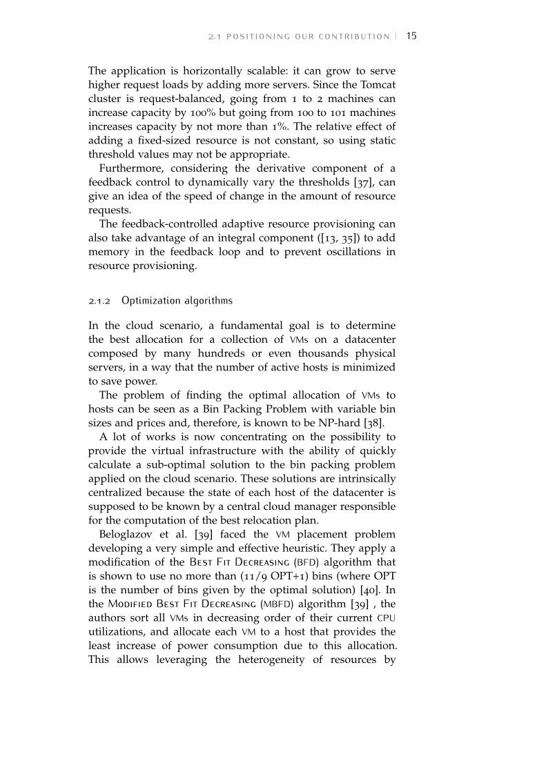
The application is horizontally scalable: it can grow to servehigher request loads by adding more servers. Since the Tomcatcluster is request-balanced, going from 1 to 2 machines canincrease capacity by 100% but going from 100 to 101 machinesincreases capacity by not more than 1%. The relative effect ofadding a fixed-sized resource is not constant, so using staticthreshold values may not be appropriate.
Furthermore, considering the derivative component of afeedback control to dynamically vary the thresholds [37], cangive an idea of the speed of change in the amount of resourcerequests.
The feedback-controlled adaptive resource provisioning canalso take advantage of an integral component ([13, 35]) to addmemory in the feedback loop and to prevent oscillations inresource provisioning.
2.1.2 Optimization algorithms
In the cloud scenario, a fundamental goal is to determinethe best allocation for a collection of VMs on a datacentercomposed by many hundreds or even thousands physicalservers, in a way that the number of active hosts is minimizedto save power.
The problem of finding the optimal allocation of VMs tohosts can be seen as a Bin Packing Problem with variable binsizes and prices and, therefore, is known to be NP-hard [38].
A lot of works is now concentrating on the possibility toprovide the virtual infrastructure with the ability of quicklycalculate a sub-optimal solution to the bin packing problemapplied on the cloud scenario. These solutions are intrinsicallycentralized because the state of each host of the datacenter issupposed to be known by a central cloud manager responsiblefor the computation of the best relocation plan.
Beloglazov et al. [39] faced the VM placement problemdeveloping a very simple and effective heuristic. They apply amodification of the Best Fit Decreasing (BFD) algorithm thatis shown to use no more than (11/9 OPT+1) bins (where OPTis the number of bins given by the optimal solution) [40]. Inthe Modified Best Fit Decreasing (MBFD) algorithm [39] , theauthors sort all VMs in decreasing order of their current CPUutilizations, and allocate each VM to a host that provides theleast increase of power consumption due to this allocation.This allows leveraging the heterogeneity of resources by
16 autonomic vm management in a single cloud
choosing the most power-efficient nodes first. The complexityof the allocation part of the algorithm is O(nm), where n is thenumber of VMs that have to be allocated and m is the numberof hosts.
When a host is detected to be in a critical overloadedcondition because of the oversubscription of resources, someSLA violation can occur and the VMs running on that servergenerally experience performance degradation. To face thiscritical situation, some VMs must be migrated to another host.The selection of the best VM to migrate can be done again withan approach involving optimization research.
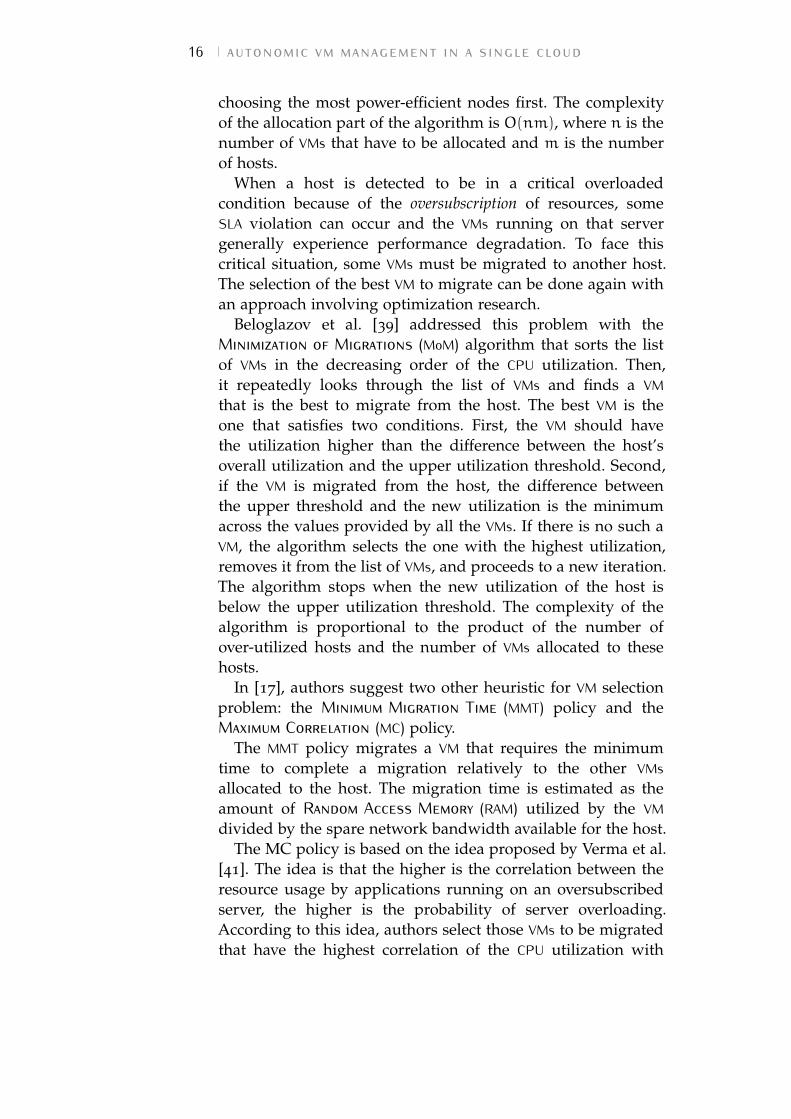
Beloglazov et al. [39] addressed this problem with theMinimization of Migrations (MoM) algorithm that sorts the listof VMs in the decreasing order of the CPU utilization. Then,it repeatedly looks through the list of VMs and finds a VMthat is the best to migrate from the host. The best VM is theone that satisfies two conditions. First, the VM should havethe utilization higher than the difference between the host’soverall utilization and the upper utilization threshold. Second,if the VM is migrated from the host, the difference betweenthe upper threshold and the new utilization is the minimumacross the values provided by all the VMs. If there is no such aVM, the algorithm selects the one with the highest utilization,removes it from the list of VMs, and proceeds to a new iteration.The algorithm stops when the new utilization of the host isbelow the upper utilization threshold. The complexity of thealgorithm is proportional to the product of the number ofover-utilized hosts and the number of VMs allocated to thesehosts.
In [17], authors suggest two other heuristic for VM selectionproblem: the Minimum Migration Time (MMT) policy and theMaximum Correlation (MC) policy.
The MMT policy migrates a VM that requires the minimumtime to complete a migration relatively to the other VMsallocated to the host. The migration time is estimated as theamount of Random Access Memory (RAM) utilized by the VMdivided by the spare network bandwidth available for the host.
The MC policy is based on the idea proposed by Verma et al.[41]. The idea is that the higher is the correlation between theresource usage by applications running on an oversubscribedserver, the higher is the probability of server overloading.According to this idea, authors select those VMs to be migratedthat have the highest correlation of the CPU utilization with
2.1 positioning our contribution 17
other VMs. To estimate the correlation between CPU utilizationsby VMs, they apply the multiple correlation coefficient [42]. It isused in multiple regression analysis to assess the quality of theprediction of the dependent variable. The multiple correlationcoefficient corresponds to the squared correlation between thepredicted and the actual values of the dependent variable. Itcan also be interpreted as the proportion of the variance of thedependent variable explained by the independent variables.
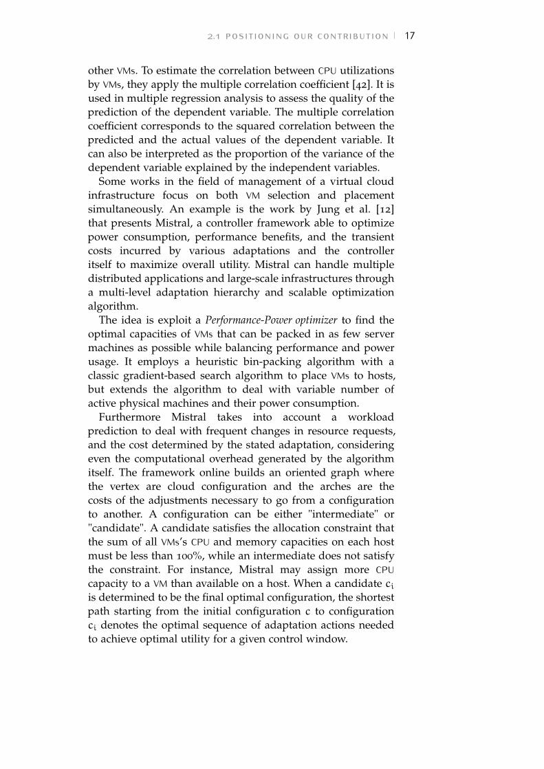
Some works in the field of management of a virtual cloudinfrastructure focus on both VM selection and placementsimultaneously. An example is the work by Jung et al. [12]that presents Mistral, a controller framework able to optimizepower consumption, performance benefits, and the transientcosts incurred by various adaptations and the controlleritself to maximize overall utility. Mistral can handle multipledistributed applications and large-scale infrastructures througha multi-level adaptation hierarchy and scalable optimizationalgorithm.
The idea is exploit a Performance-Power optimizer to find theoptimal capacities of VMs that can be packed in as few servermachines as possible while balancing performance and powerusage. It employs a heuristic bin-packing algorithm with aclassic gradient-based search algorithm to place VMs to hosts,but extends the algorithm to deal with variable number ofactive physical machines and their power consumption.
Furthermore Mistral takes into account a workloadprediction to deal with frequent changes in resource requests,and the cost determined by the stated adaptation, consideringeven the computational overhead generated by the algorithmitself. The framework online builds an oriented graph wherethe vertex are cloud configuration and the arches are thecosts of the adjustments necessary to go from a configurationto another. A configuration can be either "intermediate" or"candidate". A candidate satisfies the allocation constraint thatthe sum of all VMs’s CPU and memory capacities on each hostmust be less than 100%, while an intermediate does not satisfythe constraint. For instance, Mistral may assign more CPUcapacity to a VM than available on a host. When a candidate ciis determined to be the final optimal configuration, the shortestpath starting from the initial configuration c to configurationci denotes the optimal sequence of adaptation actions neededto achieve optimal utility for a given control window.
18 autonomic vm management in a single cloud
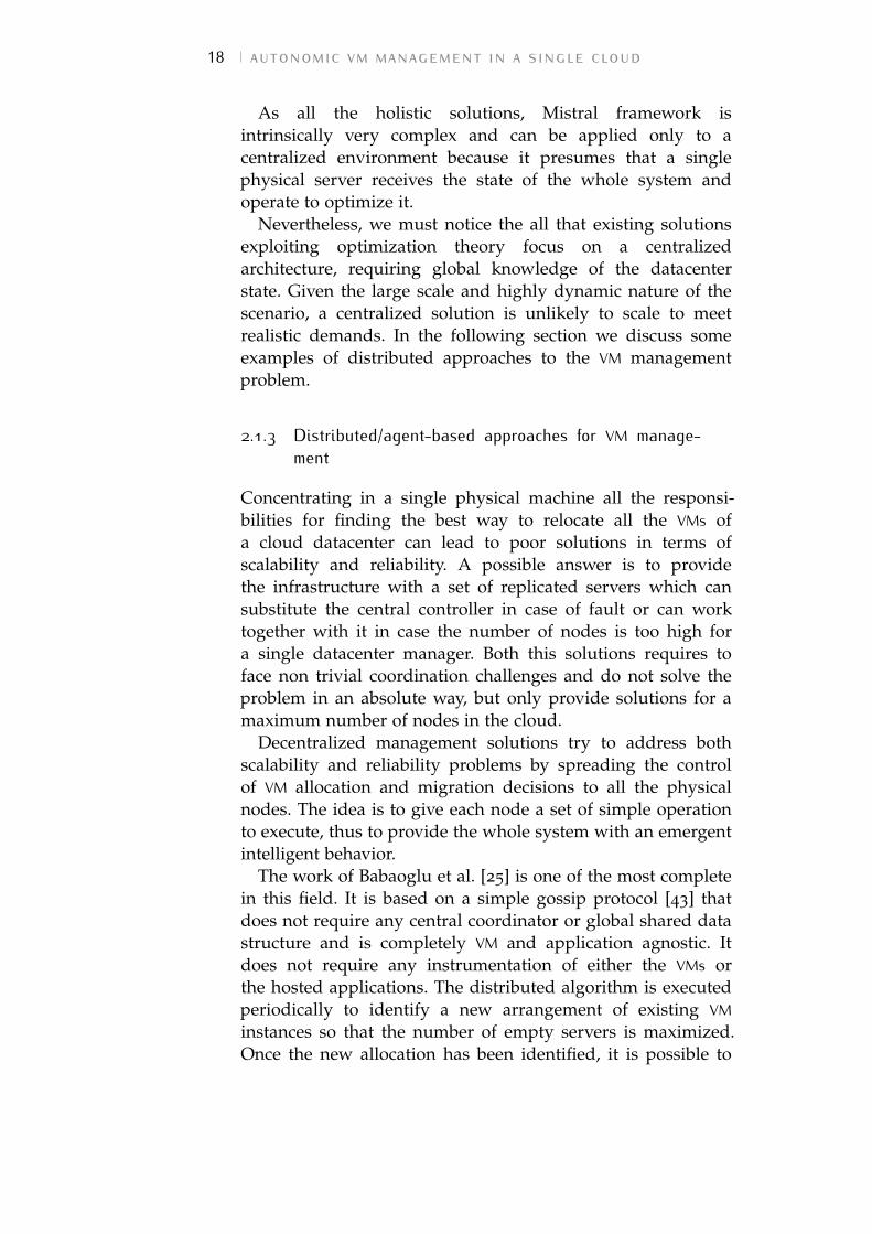
As all the holistic solutions, Mistral framework isintrinsically very complex and can be applied only to acentralized environment because it presumes that a singlephysical server receives the state of the whole system andoperate to optimize it.
Nevertheless, we must notice the all that existing solutionsexploiting optimization theory focus on a centralizedarchitecture, requiring global knowledge of the datacenterstate. Given the large scale and highly dynamic nature of thescenario, a centralized solution is unlikely to scale to meetrealistic demands. In the following section we discuss someexamples of distributed approaches to the VM managementproblem.
2.1.3 Distributed/agent-based approaches for VM manage-ment
Concentrating in a single physical machine all the responsi-bilities for finding the best way to relocate all the VMs ofa cloud datacenter can lead to poor solutions in terms ofscalability and reliability. A possible answer is to providethe infrastructure with a set of replicated servers which cansubstitute the central controller in case of fault or can worktogether with it in case the number of nodes is too high fora single datacenter manager. Both this solutions requires toface non trivial coordination challenges and do not solve theproblem in an absolute way, but only provide solutions for amaximum number of nodes in the cloud.
Decentralized management solutions try to address bothscalability and reliability problems by spreading the controlof VM allocation and migration decisions to all the physicalnodes. The idea is to give each node a set of simple operationto execute, thus to provide the whole system with an emergentintelligent behavior.
The work of Babaoglu et al. [25] is one of the most completein this field. It is based on a simple gossip protocol [43] thatdoes not require any central coordinator or global shared datastructure and is completely VM and application agnostic. Itdoes not require any instrumentation of either the VMs orthe hosted applications. The distributed algorithm is executedperiodically to identify a new arrangement of existing VMinstances so that the number of empty servers is maximized.Once the new allocation has been identified, it is possible to
2.1 positioning our contribution 19
migrate VMs to their final destination using the live migrationfeature provided by most VM monitors.
An overlay network is built and maintained using a peersampling service which provides each node with peers toexchange information with. The peer sampling service isimplemented as follows: each node periodically sends its localview (i.e., list of VMs currently hosted) to K neighbors (i.e.,other peers hosting VMs), and builds a new local view bymerging the old one with those received by neighbors. ThusBabaoglu implicitly assumes each node of the datacenter caneasily communicate with each other.
Each physical server has a map Hi of the current VMallocated, a Passive and an Active Thread running on it.
The Active Thread is executed each δ time units; iteratesover each neighbor j, to which it sends the current number ofhosted VMs; it then receives an updated map Hi of allocation(which is possibly different from the current one), and updatesit accordingly. Each server must keep track of the initiallocation of each VM it receives, so that at the end it can pull theassigned VMs from their original location.
The Passive Thread listens for messages coming from theother peers. Upon receiving the allocation map Hj from peerj, the server decides whether some VMs should be pushed toj, or pulled from it. VMs are always transferred from the leastloaded peer to the most loaded one; the number of VMs totransfer is limited by the residual capacity of the receivingnode.
This work does not address the important issues of decidingwhich specific VM to migrate; probably it makes sense totransfer those with smaller memory footprint, so that thetransferred image is smaller.
Since neighborhoods of physical servers are always changingduring the protocol execution, the information about neededmigrations are spread across the datacenter environment,without a central management node required.
However, this approach does not take into account that in aphysical cloud datacenter the network is typically organizedin a tree configuration, with high level nodes prone to bebottleneck in an intra-cloud communication. Thus, makingevery node able to exchange information with each other maycongestionate the network.
The same issue can be pointed out in the work by Tighe etal. [44] where an overloaded host determines the minimum
20 autonomic vm management in a single cloud
amount of CPU required to be available on another host tomigrate out one of its VMs and relieve the stress situation. Tothis purpose, the node broadcasts a resource request messageto all other hosts.
In [44], each host monitors its resource utilization on aperiodic interval, every 5 minutes, and performs a checkfor stress or under-utilization by comparing average CPUutilization over the last 5 monitoring intervals with thresholdvalues. Taking into account the past load conditions can giveto the monitoring system an idea of how much fast theresource utilization is changing, thus recalling the advantagesof a derivative component in an automated controller.
An important element of Tighe study [44] is the ideaof reducing thrashing between highly utilized hosts, byimplementing a relocation freeze, preventing a host fromoffering resources for a specified amount of time after thesame host evicts a VM. Indeed, this mechanism can givememory to the system similarly to the integral componentin a feedback automated controller and prevent oscillationsbetween provisioning and de-provisioning of physical hosts.
We took inspiration from distributed management solutionsto build an alternative decentralized protocol of interactionbetween physical hosts [45]. The goal is to find the bestinteraction that maximize the information exchanged withoutcreating communication overhead and VM performancedegradation.
We propose a novel decentralized way [46] to apply a VMmigration policy to the cloud: we imagine the datacenter ispartitioned into a collection of overlapping neighborhoods, ineach of which a local reallocation strategy is applied. Takingadvantage from the overlapping, the VM redistribution planpropagates on the global cloud.
We analyze the effects of this approach by comparingthem with the centralized application of the same policy.In particular we focus on the definition of the DistributedAutonomic Migration (DAM) protocol, used by cloud’s physicalhosts to communicate and get a common decision as regardsthe reallocation of VMs, according to a predefined global goal(e.g. power-saving, load balancing, etc.) [47].
Table 2.1 summarizes the main features of the referredworks in the field of VM management. The last two lines referto our contributions presented in the next section.
2.1 positioning our contribution 21
Tabl
e2.
1:M
ain
feat
ures
ofth
ew
orks
inth
efie
ldof
VMm
anag
emen
t
Con
trib
utio
nA
ddre
ssed
prob
lem
Goa
lEm
ploy
edte
chni
que
Thr
esho
ldm
echa
nism
Urg
aonk
aret
al.[
33]
Clu
ster
com
men
sura
tion
(num
ber
ofVM
sto
pro-
vide
for
appl
icat
ion)
QoS
Que
uing
theo
ry-
Soun
dara
raja
net
al.[
32]
Clu
ster
com
men
sura
tion
QoS
Con
trol
theo
rypr
opor
tion
al/s
tati
c
Lim
etal
.[13]
Hol
isti
cQ
oSC
ontr
olth
eory
deri
vati
vean
din
tegr
al
Pada
laet
al.[
35
]VM
com
men
sura
tion
QoS
Con
trol
theo
ryde
riva
tive
and
inte
gral
Lore
ti[3
7]
Hol
isti
cQ
oSC
ontr
olth
eory
deri
vati
ve
Aba
waj
yet
al.[
39]
Hol
isti
cpo
wer
savi
ng&
load
bala
ncin
gH
euri
stic
stat
ic
MM
T-Be
logl
azov
etal
.[17]
VMSe
lect
ion
min
mig
r.ti
me
Heu
rist
ic-
MC-
Belo
glaz
ovet
al.[
17]
VMSe
lect
ion
load
bala
ncin
gH
euri
stic
-
Jung
etal
.[12]
Hol
isti
cpo
wer
savi
ng&
load
bala
ncin
gH
euri
stic
-
Mar
zolla
etal
.[25]
Hol
isti
cpo
wer
savi
ngA
gent
sst
atic
Tigh
eet
al.[
44
]H
olis
tic
pow
ersa
ving
&lo
adba
lanc
ing
Age
nts
pseu
do-d
eriv
ativ
e
Lore
tiet
al.[
48
]H
olis
tic
load
bala
ncin
gA
gent
stu
nabl
e
Lore
tiet
al.[
49
]H
olis
tic
pow
ersa
ving
&lo
adba
lanc
ing
Age
nts
tuna
ble
22 autonomic vm management in a single cloud
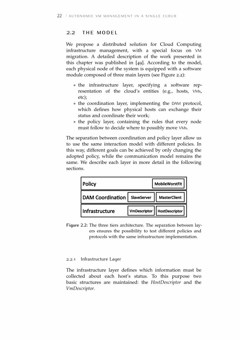
2.2 the modelWe propose a distributed solution for Cloud Computinginfrastructure management, with a special focus on VMmigration. A detailed description of the work presented inthis chapter was published in [49]. According to the model,each physical node of the system is equipped with a softwaremodule composed of three main layers (see Figure 2.2):
• the infrastructure layer, specifying a software rep-resentation of the cloud’s entities (e.g., hosts, VMs,etc);• the coordination layer, implementing the DAM protocol,
which defines how physical hosts can exchange theirstatus and coordinate their work;• the policy layer, containing the rules that every node
must follow to decide where to possibly move VMs.
The separation between coordination and policy layer allow usto use the same interaction model with different policies. Inthis way, different goals can be achieved by only changing theadopted policy, while the communication model remains thesame. We describe each layer in more detail in the followingsections.
Figure 2.2: The three tiers architecture. The separation between lay-ers ensures the possibility to test different policies andprotocols with the same infrastructure implementation.
2.2.1 Infrastructure Layer
The infrastructure layer defines which information must becollected about each host’s status. To this purpose twobasic structures are maintained: the HostDescriptor and theVmDescriptor.
2.2 the model 23
The HostDescriptor can be seen as a bin with a given capacityable to host a number of VMs, each one with a specificrequest for computational resources. We only take into accountthe amount of computational power in terms of Millionsof Instructions Per Second (MIPS) offered by each host andrequested by a VM. An empty HostDescriptor represents an idleserver that can therefore be put in a sleep mode or switched-offto save power.
The HostDescriptor contains not only a collection ofVmDescriptors really allocated on it (the current map), but alsoa temporary collection (the future map) initialized as a copyof the real one and exchanged between hosts according tothe defined protocol. During interactions only the temporarycopy is updated and, when the system reaches a commonreallocation decision, the future map is used to apply themigrations.
In a distributed environment, where each node can beaware only of the state of a local neighborhood of nodes,the number of worthless migrations can be very high. Thus,this double-map mechanism is used to limit the number ofmigrations (as we describe in Chapter 2.2.2), by performingthem only when all the hosts reach a common distributeddecision.
Each VM is also equipped with a migration history keepingtrack of all the hosts where it was previously allocated. For thesake of simplicity, we assume that a VM cannot change its CPUrequest during the simulation period.
The CPU model
The amount Uh of CPU MIPS used by the host h is calculated asfollows:
Uh =∑
vm∈currentVmMaph
mvmTvm
100(2.1)
where currentVmMaph is the set of VMs currently allocatedon host h; Tvm is the total CPU MIPS that a virtual machine vmcan request; and mvm is the percentage of this total that iscurrently used.
Indeed, we consider a simplified model in which the totalMIPS executed by the node can be seen as the sum of MIPSused by each hosted virtual machine. In fact, the model
24 autonomic vm management in a single cloud
does not take into account the power consumed by thephysical machines to realize virtualization and to manage theirresources.
2.2.2 Coordination Layer
The coordination layer implements the DAM protocol, whichdefines the sequence of messages that hosts exchange in orderto get a common migration decision and realize the definedpolicy.
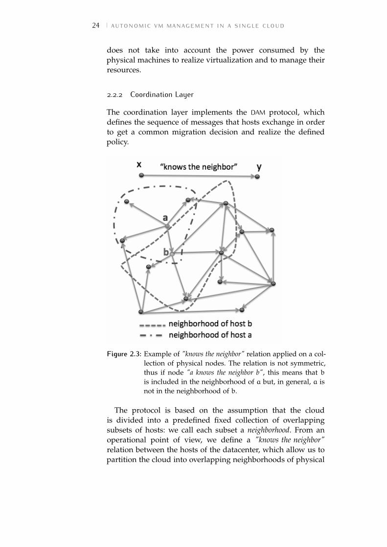
Figure 2.3: Example of "knows the neighbor" relation applied on a col-lection of physical nodes. The relation is not symmetric,thus if node "a knows the neighbor b", this means that bis included in the neighborhood of a but, in general, a isnot in the neighborhood of b.
The protocol is based on the assumption that the cloudis divided into a predefined fixed collection of overlappingsubsets of hosts: we call each subset a neighborhood. From anoperational point of view, we define a "knows the neighbor"relation between the hosts of the datacenter, which allow us topartition the cloud into overlapping neighborhoods of physical
2.2 the model 25
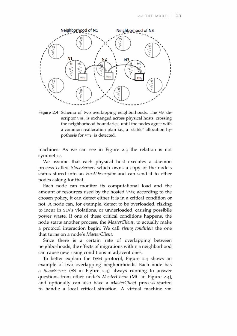
Figure 2.4: Schema of two overlapping neighborhoods. The VM de-scriptor vmi is exchanged across physical hosts, crossingthe neighborhood boundaries, until the nodes agree witha common reallocation plan i.e., a "stable" allocation hy-pothesis for vmi is detected.
machines. As we can see in Figure 2.3 the relation is notsymmetric.
We assume that each physical host executes a daemonprocess called SlaveServer, which owns a copy of the node’sstatus stored into an HostDescriptor and can send it to othernodes asking for that.
Each node can monitor its computational load and theamount of resources used by the hosted VMs; according to thechosen policy, it can detect either it is in a critical condition ornot. A node can, for example, detect to be overloaded, riskingto incur in SLA’s violations, or underloaded, causing possibilepower waste. If one of these critical conditions happens, thenode starts another process, the MasterClient, to actually makea protocol interaction begin. We call rising condition the onethat turns on a node’s MasterClient.
Since there is a certain rate of overlapping betweenneighborhoods, the effects of migrations within a neighborhoodcan cause new rising conditions in adjacent ones.
To better explain the DAM protocol, Figure 2.4 shows anexample of two overlapping neighborhoods. Each node hasa SlaveServer (SS in Figure 2.4) always running to answerquestions from other node’s MasterClient (MC in Figure 2.4),and optionally can also have a MasterClient process startedto handle a local critical situation. A virtual machine vm
26 autonomic vm management in a single cloud
allocated to an underloaded node N1 can be moved out of iton N2 and, as a consequence of the execution of the protocolin the adjacent neighborhood of N3, it can be moved againfrom N2 to N3. It is worth to notice that node N2, as eachnode of the datacenter, has its own fixed neighborhood, but itstarts to interact with it (by means of a MasterClient) only if arising condition is observed.
Note that N1’s MasterClient must have N2 in itsneighborhood to interact with it, but the SlaveServer of N2
can answer to requests by any MasterClient and, if a criticalsituation is detected (so that N2 MasterClient is started) itsneighborhood does not necessarily include N1.
As regards this environment, we must remark that themigration policy should be properly implemented in order toprevent never-ending cycles in the migration process.
Algorithms 1 and 2 reports the interaction code executedby the MasterClient and the SlaveServer, respectively. TheMasterClient procedure takes as input the list of SlaveServerneighbors ssNeighList and an integer parameter maxRound. TheSlaveServer procedure takes the HostDescriptor h of the nodeon which it is running. If the SlaveServer detects a criticalconditions on the host, makes a MasterClient process start(lines 1-2 in Algorithm 2).
We must ensure that the neighbors’s states the MasterClientobtains, are consistent from the beginning to the end of theinteraction. For this reason, a two-phase protocol is adopted:
DAM Phase 1
As we can see in lines 5-9 of Algorithm1, the MasterClientsends a message to all the SlaveServers neighbors ss to collecttheir HostDescriptors h. This message also works as a lockmessage: when the SlaveServer receives it, locks his state, sothat no interactions with other MasterClients can take place(lines 5-11 in Algorithm 2). If a MasterClient sends a requestto a locked SlaveServer, simply waits for the SlaveServer to beunlocked and to send its state.
DAM Phase 2
The MasterClient compares all the received neighbor’sHostDescriptors with a previous copy he stored (line 10 inAlgorithm 1). If the future map is changed, performs phase 2A,
2.2 the model 27
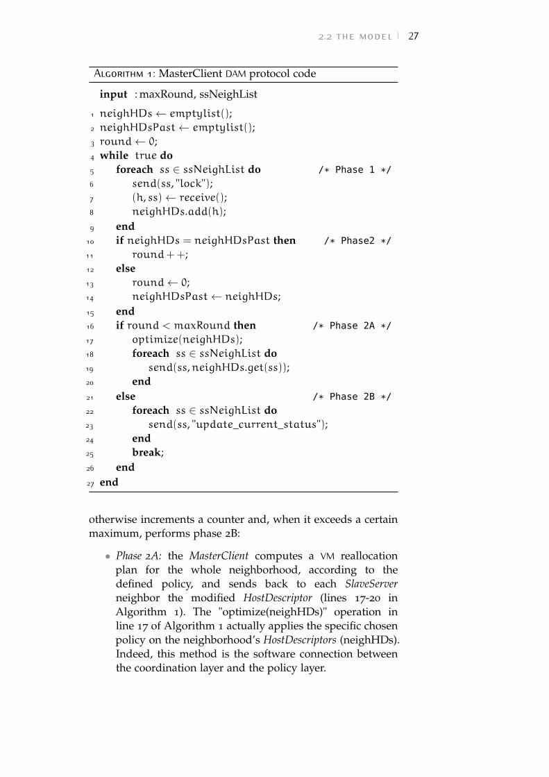
Algorithm 1: MasterClient DAM protocol code
input : maxRound, ssNeighList
1 neighHDs← emptylist();2 neighHDsPast← emptylist();3 round← 0;4 while true do5 foreach ss ∈ ssNeighList do /* Phase 1 */
6 send(ss, "lock");7 (h, ss)← receive();8 neighHDs.add(h);9 end
10 if neighHDs = neighHDsPast then /* Phase2 */
11 round++;12 else13 round← 0;14 neighHDsPast← neighHDs;15 end16 if round < maxRound then /* Phase 2A */
17 optimize(neighHDs);18 foreach ss ∈ ssNeighList do19 send(ss,neighHDs.get(ss));20 end21 else /* Phase 2B */
22 foreach ss ∈ ssNeighList do23 send(ss, "update_current_status");24 end25 break;26 end27 end
otherwise increments a counter and, when it exceeds a certainmaximum, performs phase 2B:
• Phase 2A: the MasterClient computes a VM reallocationplan for the whole neighborhood, according to thedefined policy, and sends back to each SlaveServerneighbor the modified HostDescriptor (lines 17-20 inAlgorithm 1). The "optimize(neighHDs)" operation inline 17 of Algorithm 1 actually applies the specific chosenpolicy on the neighborhood’s HostDescriptors (neighHDs).Indeed, this method is the software connection betweenthe coordination layer and the policy layer.
28 autonomic vm management in a single cloud
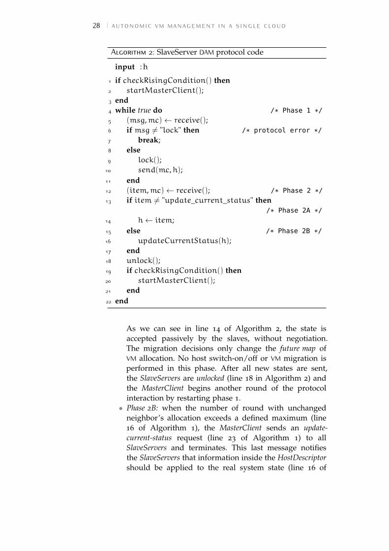
Algorithm 2: SlaveServer DAM protocol code
input : h
1 if checkRisingCondition() then2 startMasterClient();3 end4 while true do /* Phase 1 */
5 (msg,mc)← receive();6 if msg 6= "lock" then /* protocol error */
7 break;8 else9 lock();
10 send(mc,h);11 end12 (item,mc)← receive(); /* Phase 2 */
13 if item 6= "update_current_status" then/* Phase 2A */
14 h← item;15 else /* Phase 2B */
16 updateCurrentStatus(h);17 end18 unlock();19 if checkRisingCondition() then20 startMasterClient();21 end22 end
As we can see in line 14 of Algorithm 2, the state isaccepted passively by the slaves, without negotiation.The migration decisions only change the future map ofVM allocation. No host switch-on/off or VM migration isperformed in this phase. After all new states are sent,the SlaveServers are unlocked (line 18 in Algorithm 2) andthe MasterClient begins another round of the protocolinteraction by restarting phase 1.• Phase 2B: when the number of round with unchanged
neighbor’s allocation exceeds a defined maximum (line16 of Algorithm 1), the MasterClient sends an update-current-status request (line 23 of Algorithm 1) to allSlaveServers and terminates. This last message notifiesthe SlaveServers that information inside the HostDescriptorshould be applied to the real system state (line 16 of
2.2 the model 29
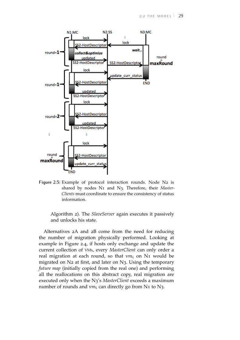
Figure 2.5: Example of protocol interaction rounds. Node N2 isshared by nodes N1 and N3. Therefore, their Master-Clients must coordinate to ensure the consistency of statusinformation.
Algorithm 2). The SlaveServer again executes it passivelyand unlocks his state.
Alternatives 2A and 2B come from the need for reducingthe number of migration physically performed. Looking atexample in Figure 2.4, if hosts only exchange and update thecurrent collection of VMs, every MasterClient can only order areal migration at each round, so that vmi on N1 would bemigrated on N2 at first, and later on N3. Using the temporaryfuture map (initially copied from the real one) and performingall the reallocations on this abstract copy, real migration areexecuted only when the N3’s MasterClient exceeds a maximumnumber of rounds and vmi can directly go from N1 to N3.
30 autonomic vm management in a single cloud
The same example is represented in Figure 2.5. N2 is sharedby the MasterClients of nodes N1 and N3. Two concurrentsessions of the protocol must synchronize in order to maintainthe status information consistent. Therefore, node N3 waitsuntil N2 status is updated and released by N1. If no concurrentinteractions are taking place in adjacent neighborhoods,the MasterClient receives an unchanged HostDescriptor andincrements the value of the round counter.
As a result of DAM protocol, the consensus on migration ofVMs is not for the entire infrastructure, but is distributed acrossthe neighborhoods. This element must be taken into accountwhile implementing the policy layer.
2.2.3 Policy Layer
Depending on the algorithm implemented in the Policy layer,different management goals can be achieved.
We used DAM infrastructure to study the performance oftwo different policies: Mobile Balance (MB) and Mobile WorstFit (MWF). The following sections show the policies in detail aswell as their performance evaluation.
2.3 mobile balance policyMB is a novel policy aiming to maintain the computationalload of physical nodes balanced. The content of this chapterhas been published in [48].
MB exploits a fixed threshold FTH_UP and a dynamicthreshold MTH_UP to detect rising conditions. The fixedthreshold identifies absolute risky situations: if the host ismore loaded than FTH_UP, SLA violations may occur. Thedynamic threshold MTH_UP represents the upper value thatcannot be exceeded in order to maintain the neighborhoodbalanced.
According to the DAM coordination protocol, at each iterationthe MasterClient collects the temporary VM allocation map ofthe neighbors and executes a MB optimization as detailed inAlgorithm 3: the MasterClient calculates the average of resourceutilization in his neighborhood (calculateNeighAverage() inline 1 of Algorithm 3) and uses it to compute the dynamicthreshold (MTH_UP) by adding a tolerance interval t (line 2 of
2.3 mobile balance policy 31
Algorithm 3: MB policy
input : h, t, FTH_UP
1 ave← calculateNeighAverage() ;2 MTH_UP ← ave+ t ;3 u← h.getLoad() ;4 if u > FTH_UP or u > MTH_UP then5 vmList← selectVms() ;6 end7 if vmList.size 6= 0 then8 worstFitMigrateAll(vmList) ;9 end
Algorithm 3). Then the MasterClient checks its HostDescriptorh and collects the current computational load u by invokinga specific getLoad() method on the HostDescriptor (line 3 ofAlgorithm 3).
The computational load u of the host is compared tofixed and dynamic thresholds: if it is detected to be higherthan FTH_UP or MTH_UP, then the selectVms() operation isinvoked to pick (from the host h temporary state) only the lessloaded VMs whose migration will result in the host load to goback under both MTH_UP and FTH_UP. selectVm() appliesthe MoM algorithm from Beloglazov et al. [39] and is detailedin Algorithm 4. Differently from [39], we select the thresholdthr as the minimum between FTH_UP and MTH_UP.
The list of chosen VMs vmList is finally migratedto neighbors by means of a modified worst-fit policy(worstFitMigrateAll(vmList) in line 8 of Algorithm 3).
As shown in Algorithm 5, the worstFitMigrateAll
procedure takes as input the list of vm to move (vmList), thehost h where they are currently allocated, the list offNeighListof switched-off hosts in h’s neighborhood (if any) andwNeighList of all the working neighbors of h. The procedureconsiders the VMs by decreasing CPU request and, according tothe principles of worst-fit algorithm, tries to migrate it to theneighbor n with the highest value of free capacity (lines 5 to13 of Algorithm 5). This ensure that neighbors with low CPUutilization are preferred.
Finally, if no hosts in wNeighList can receive vm, buth is more loaded than FTH_UP, then h is in a risky
32 autonomic vm management in a single cloud
situation because performance degradation can occur. Thus, aswitched-off neighbor is woken up (line 15 of Algorithm 5).worstFitMigrateAll(vmList) operates in a "all-or-none"
way, such that the migrations are committed on the futuremaps (line 22 of Algorithm 5) only if it is possible to reallocateall the VMs in the list (i.e., without making other hosts toexceed FTH_UP), otherwise no action is performed (line 17 ofAlgorithm 5).
As shown in Figure 2.6, suppose that a protocol execution byhb’s MasterClient decides to migrate to hb a VM vmi currentlyallocated on hc. When the SlaveServer of hb is unlocked, the
Algorithm 4: selectVms() procedure
input : h, MTH_UP, FTH_UPoutput : vmsToMove
1 u← h.getLoad();2 vmList← h.getFutureVmMap() ;3 vmList.sortDecreasingLoad();4 minU←∞;5 bestVm← null;6 thr← min{FTH_UP,MTH_UP};7 vmsToMove = emptyList();8 while u > thr do9 foreach vm ∈ vmList do
10 var← vm.getLoad() − u+ thr;11 if var > 0 then12 if var < minU then13 minU← var;14 bestVm← vm;15 end16 else17 if minU = ∞ then18 bestVm← vm;19 end20 break;21 end22 end23 u = u− bestVm.getLoad();24 vmsToMove.add(bestVm);25 vmList.remove(bestVm);26 end
2.3 mobile balance policy 33
Algorithm 5: worstFitMigrateAll() procedure
input : vmList, h, offNeighList, wNeighList
1 vmList.sortDecreasingLoad() ;2 foreach vm ∈ vmList do3 vmU← vm.getLoad();4 maxAvail← 0;bestHost← null;5 foreach n ∈ wNeighList do6 if n /∈ vm.getMigrationHistory() then7 avail← FTH_UP−n.getLoad() + vmU ;8 if avail > maxAvail then9 maxAvail← avail ;
10 bestHost← n ;11 end12 end13 end14 if bestHostnull and !empty(offNeighList) and
u > FTH_UP then15 bestHost← offNeighList.get(0) ;16 else
/* all-or-none behavior */
17 migrationMap← null ;18 break;19 end20 migrationMap.add(vm,bestHost) ;21 end22 commitOnFutureMap(migrationMap) ;
policy execution on ha’s MasterClient can decide to put vmi
into ha. Now if hc has a MasterClient running, and decides tomigrate vmi back to hc, then hc can take the same decision asbefore and a loop in vmi migration starts. If this happens, thedistributed system will never converge to a common decision.In order to face this problem, the MB policy exploits themigration history inside each VmDescriptor to avoid loops inreallocation: a VM can be migrated only on a host that it nevervisited before. Once the distributed autonomic infrastructurereach a common decision, the migration history of each VM isdeleted.
To prevent the case in which a VM cannot be migrated awaybecause it visited all the nodes around her current allocation,we implemented the migration history as an ever-updating list
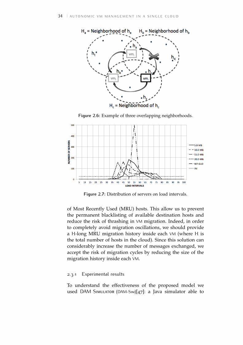
34 autonomic vm management in a single cloud
Figure 2.6: Example of three overlapping neighborhoods.
Figure 2.7: Distribution of servers on load intervals.
of Most Recently Used (MRU) hosts. This allow us to preventthe permanent blacklisting of available destination hosts andreduce the risk of thrashing in VM migration. Indeed, in orderto completely avoid migration oscillations, we should providea H-long MRU migration history inside each VM (where H isthe total number of hosts in the cloud). Since this solution canconsiderably increase the number of messages exchanged, weaccept the risk of migration cycles by reducing the size of themigration history inside each VM.
2.3.1 Experimental results
To understand the effectiveness of the proposed model weused DAM Simulator (DAM-Sim)[47]: a Java simulator able to
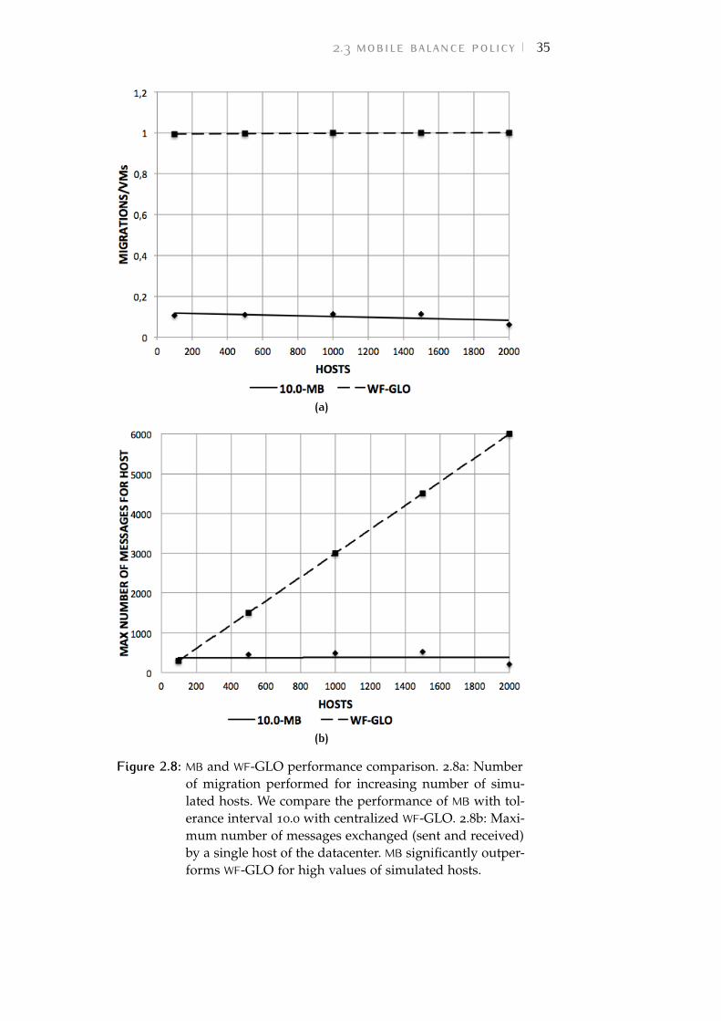
2.3 mobile balance policy 35
(a)
(b)
Figure 2.8: MB and WF-GLO performance comparison. 2.8a: Numberof migration performed for increasing number of simu-lated hosts. We compare the performance of MB with tol-erance interval 10.0 with centralized WF-GLO. 2.8b: Maxi-mum number of messages exchanged (sent and received)by a single host of the datacenter. MB significantly outper-forms WF-GLO for high values of simulated hosts.
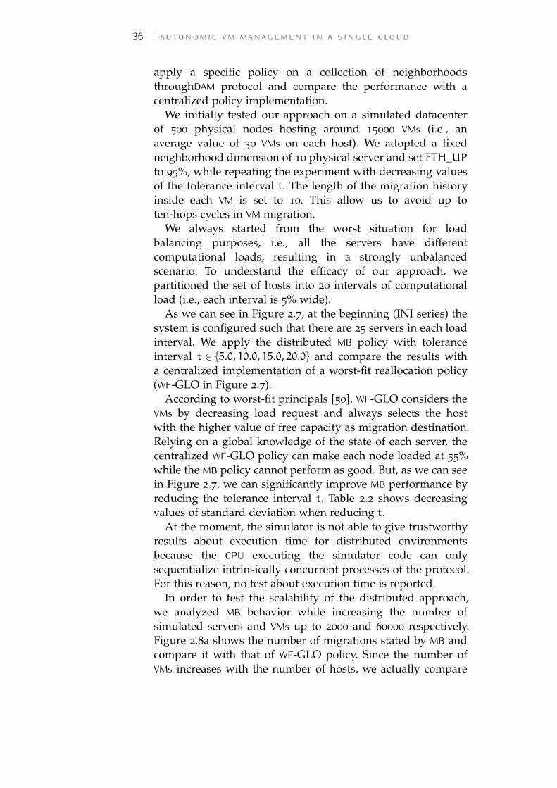
36 autonomic vm management in a single cloud
apply a specific policy on a collection of neighborhoodsthroughDAM protocol and compare the performance with acentralized policy implementation.
We initially tested our approach on a simulated datacenterof 500 physical nodes hosting around 15000 VMs (i.e., anaverage value of 30 VMs on each host). We adopted a fixedneighborhood dimension of 10 physical server and set FTH_UPto 95%, while repeating the experiment with decreasing valuesof the tolerance interval t. The length of the migration historyinside each VM is set to 10. This allow us to avoid up toten-hops cycles in VM migration.
We always started from the worst situation for loadbalancing purposes, i.e., all the servers have differentcomputational loads, resulting in a strongly unbalancedscenario. To understand the efficacy of our approach, wepartitioned the set of hosts into 20 intervals of computationalload (i.e., each interval is 5% wide).
As we can see in Figure 2.7, at the beginning (INI series) thesystem is configured such that there are 25 servers in each loadinterval. We apply the distributed MB policy with toleranceinterval t ∈ {5.0, 10.0, 15.0, 20.0} and compare the results witha centralized implementation of a worst-fit reallocation policy(WF-GLO in Figure 2.7).
According to worst-fit principals [50], WF-GLO considers theVMs by decreasing load request and always selects the hostwith the higher value of free capacity as migration destination.Relying on a global knowledge of the state of each server, thecentralized WF-GLO policy can make each node loaded at 55%while the MB policy cannot perform as good. But, as we can seein Figure 2.7, we can significantly improve MB performance byreducing the tolerance interval t. Table 2.2 shows decreasingvalues of standard deviation when reducing t.
At the moment, the simulator is not able to give trustworthyresults about execution time for distributed environmentsbecause the CPU executing the simulator code can onlysequentialize intrinsically concurrent processes of the protocol.For this reason, no test about execution time is reported.
In order to test the scalability of the distributed approach,we analyzed MB behavior while increasing the number ofsimulated servers and VMs up to 2000 and 60000 respectively.Figure 2.8a shows the number of migrations stated by MB andcompare it with that of WF-GLO policy. Since the number ofVMs increases with the number of hosts, we actually compare
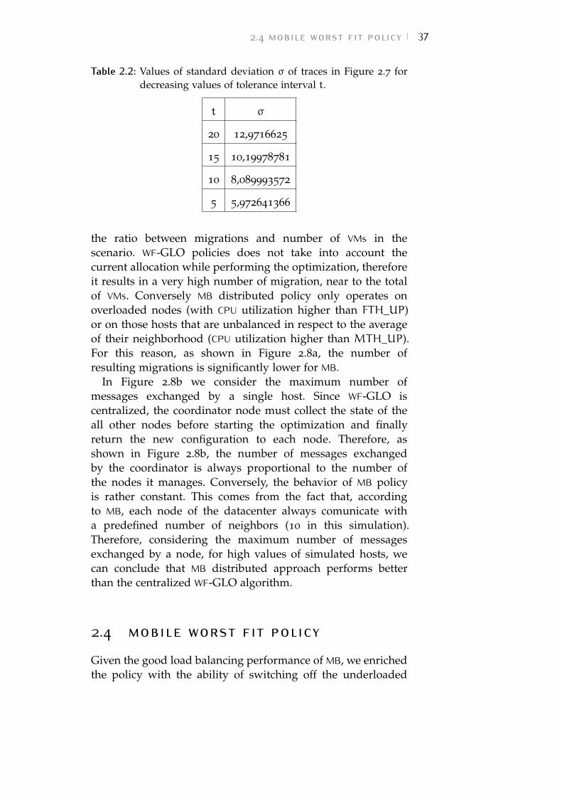
2.4 mobile worst fit policy 37
Table 2.2: Values of standard deviation σ of traces in Figure 2.7 fordecreasing values of tolerance interval t.
t σ
20 12,9716625
15 10,19978781
10 8,089993572
5 5,972641366
the ratio between migrations and number of VMs in thescenario. WF-GLO policies does not take into account thecurrent allocation while performing the optimization, thereforeit results in a very high number of migration, near to the totalof VMs. Conversely MB distributed policy only operates onoverloaded nodes (with CPU utilization higher than FTH_UP)or on those hosts that are unbalanced in respect to the averageof their neighborhood (CPU utilization higher than MTH_UP).For this reason, as shown in Figure 2.8a, the number ofresulting migrations is significantly lower for MB.
In Figure 2.8b we consider the maximum number ofmessages exchanged by a single host. Since WF-GLO iscentralized, the coordinator node must collect the state of theall other nodes before starting the optimization and finallyreturn the new configuration to each node. Therefore, asshown in Figure 2.8b, the number of messages exchangedby the coordinator is always proportional to the number ofthe nodes it manages. Conversely, the behavior of MB policyis rather constant. This comes from the fact that, accordingto MB, each node of the datacenter always comunicate witha predefined number of neighbors (10 in this simulation).Therefore, considering the maximum number of messagesexchanged by a node, for high values of simulated hosts, wecan conclude that MB distributed approach performs betterthan the centralized WF-GLO algorithm.
2.4 mobile worst fit policyGiven the good load balancing performance of MB, we enrichedthe policy with the ability of switching off the underloaded
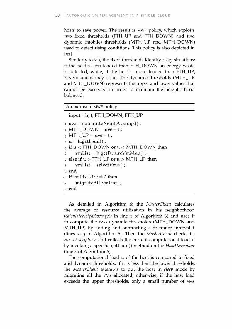
38 autonomic vm management in a single cloud
hosts to save power. The result is MWF policy, which exploitstwo fixed thresholds (FTH_UP and FTH_DOWN) and twodynamic (mobile) thresholds (MTH_UP and MTH_DOWN)used to detect rising conditions. This policy is also depicted in[51]
Similarly to MB, the fixed thresholds identify risky situations:if the host is less loaded than FTH_DOWN an energy wasteis detected, while, if the host is more loaded than FTH_UP,SLA violations may occur. The dynamic thresholds (MTH_UPand MTH_DOWN) represents the upper and lower values thatcannot be exceeded in order to maintain the neighborhoodbalanced.
Algorithm 6: MWF policy
input : h, t, FTH_DOWN, FTH_UP
1 ave = calculateNeighAverage() ;2 MTH_DOWN = ave− t ;3 MTH_UP = ave+ t ;4 u = h.getLoad() ;5 if u < FTH_DOWN or u < MTH_DOWN then6 vmList = h.getFutureVmMap() ;7 else if u > FTH_UP or u > MTH_UP then8 vmList = selectVms() ;9 end
10 if vmList.size 6= 0 then11 migrateAll(vmList) ;12 end
As detailed in Algorithm 6: the MasterClient calculatesthe average of resource utilization in his neighborhood(calculateNeighAverage() in line 1 of Algorithm 6) and uses itto compute the two dynamic thresholds (MTH_DOWN andMTH_UP) by adding and subtracting a tolerance interval t(lines 2, 3 of Algorithm 6). Then the MasterClient checks itsHostDescriptor h and collects the current computational load uby invoking a specific getLoad() method on the HostDescriptor(line 4 of Algorithm 6).
The computational load u of the host is compared to fixedand dynamic thresholds: if it is less than the lower thresholds,the MasterClient attempts to put the host in sleep mode bymigrating all the VMs allocated; otherwise, if the host loadexceeds the upper thresholds, only a small number of VMs
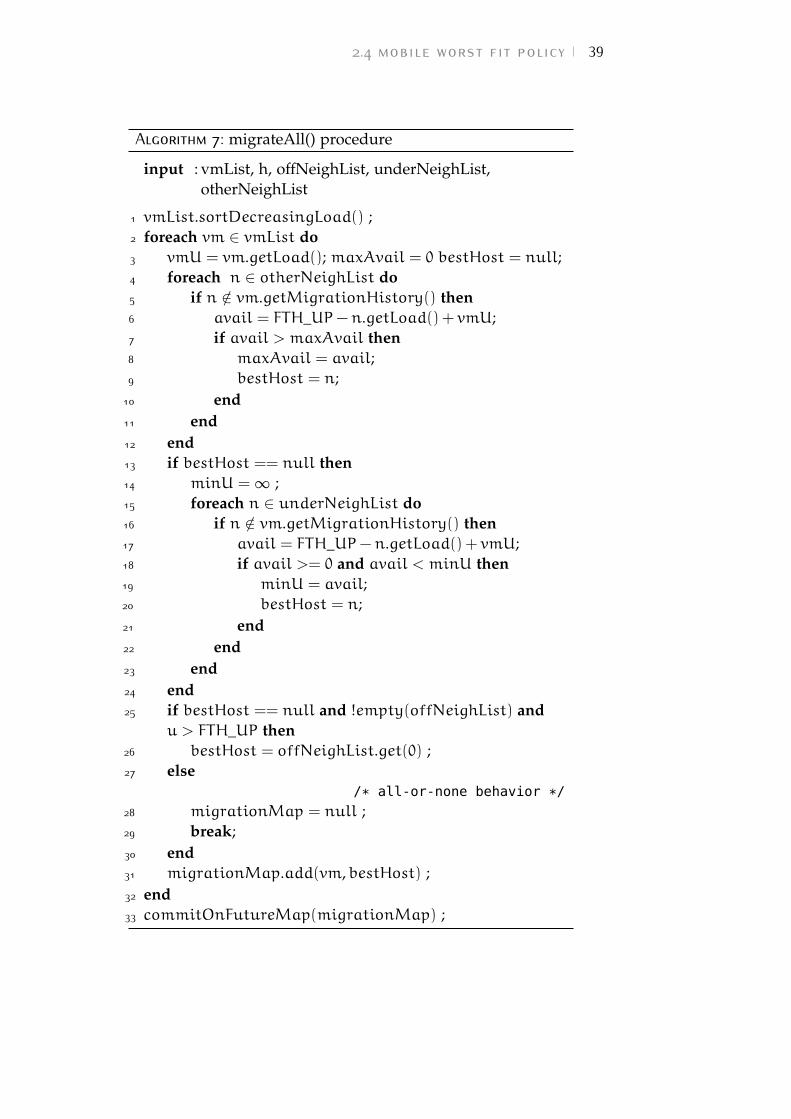
2.4 mobile worst fit policy 39
Algorithm 7: migrateAll() procedure
input : vmList, h, offNeighList, underNeighList,otherNeighList
1 vmList.sortDecreasingLoad() ;2 foreach vm ∈ vmList do3 vmU = vm.getLoad(); maxAvail = 0 bestHost = null;4 foreach n ∈ otherNeighList do5 if n /∈ vm.getMigrationHistory() then6 avail = FTH_UP−n.getLoad() + vmU;7 if avail > maxAvail then8 maxAvail = avail;9 bestHost = n;
10 end11 end12 end13 if bestHost == null then14 minU = ∞ ;15 foreach n ∈ underNeighList do16 if n /∈ vm.getMigrationHistory() then17 avail = FTH_UP−n.getLoad() + vmU;18 if avail >= 0 and avail < minU then19 minU = avail;20 bestHost = n;21 end22 end23 end24 end25 if bestHost == null and !empty(offNeighList) and
u > FTH_UP then26 bestHost = offNeighList.get(0) ;27 else
/* all-or-none behavior */
28 migrationMap = null ;29 break;30 end31 migrationMap.add(vm,bestHost) ;32 end33 commitOnFutureMap(migrationMap) ;
40 autonomic vm management in a single cloud
are selected for migration. As we can see in lines 5, 6 ofAlgorithm6, if the computational load u is less than thefixed (FTH_DOWN) or the dynamic (MTH_DOWN) lowerthresholds, all the VMs of the host are collected for migrationinto an array vmList. h.getFutureVmMap() in line 6 is themethod to collect the temporary allocation. Indeed in thisphase, the policy only works on a copy of the real VM allocationmap, because according toDAM protocol, all the migrationswill be performed only when the whole datacenter reach acommon decision.
As suggested by MB, if the load u is detected to behigher than the fixed (FTH_UP) or dynamic (MTH_UP)upper thresholds, then the selectVm() operation is invoked(Algorithm 4).
The list of chosen VMs vmList is finally migrated to neighborsby means of a modified worst-fit policy (migrateAll(vmList)in line 11 of Algorithm 6). As shown in Algorithm 7, themigrateAll procedure takes as input the list of vm to move(vmList), the host h where they are currently allocated, the listoffNeighList of switched-off hosts in h’s neighborhood, theunderNeighList of h’s neighbors with load level lower thanFTH_DOWN, and otherNeighList of all the other neighborsof h. The procedure considers the VMs by decreasing CPUrequest and, according to the principles of worst-fit algorithm,tries to migrate it to the neighbor n with the highest valueof free capacity (lines 2-12 of Algorithm 7). If no neighbor inotherNeighList can receive the vm, the underNeighList isconsidered with a best-fit approach (lines 13-24 of Algorithm7), thus allocating vm on the most loaded host of the list. Thisensure that neighbors with CPU utilization near to FTH_DOWNare preferred, while less loaded ones remain unchanged andwill be hopefully switched-off by other protocol’s interactions.Finally, if neither hosts in underNeighList can receive vm (e.g,because the list is empty), but h is more loaded than FTH_UP,then h is in a risky situation because SLA’s violations can occur.Thus, as in MB, a switched-off neighbor is woken up (line 26 ofAlgorithm 7).
Similarly to worstFitMigrateAll(vmList) of MB policy,migrateAll(vmList) operates in a "all-or-none" way (line 33 ofAlgorithm 7).
2.4 mobile worst fit policy 41
2.4.1 Experimental results
To understand the effectiveness of MWF, we tested it on DAM-Sim[52]. In this case, we evaluated the approach on a set of 100
physical nodes hosting around 3000 VMs (i.e., an average valueof 30 VMs on each host), repeating every experiment with anincreasing average load on each physical server.
According to the tuning tests of MoM algorithm [17], theFTH_DOWN and FTH_UP thresholds have been fixed at 25%and 95%, respectively, while we initially set the toleranceinterval t for load balancing at 8%.
We start from the worst situation for power-saving purposes,i.e., all the servers are switched on and have the samecomputational load within the fixed thresholds. To make theDAM protocol start we need some lack of balance in thedatacenter, so we forced 20 hosts to be more loaded and20 hosts to be less loaded than the datacenter average value.These hosts are randomly chosen in every experiment.
In Figure 2.9, we compare the MWF performance with 5
and 10 nodes in each neighborhood (MWF5 and MWF10 series),with the application of a centralized best fit policy (BF-GLOin Figure 2.9a) [47]. We also show the performance of BF: abest fit policy applied in a distributed way by means of DAMprotocol. BF exploits the two-phase lock protocol, therefore,each time a server detects to be underloaded or overloaded,it start reconsidering the current VM allocation for the wholeneighborhood. Details about BF implementation can be foundin [47].
Figures 2.9a and 2.9b show the number of servers switchedon at the end of the MWF and BF executions. As weexpected, the DAM protocol cannot perform better than aglobal algorithm. Indeed, the global best fit policy (BF-GLO)can always switch off a higher rate of servers resulting inthe lower trend. Furthermore, as regards the power savingobjective, we can see that BF perform better than MWF for allthe selected neighborhood dimensions. This comes from thedifferent objectives of the two policies: MWF tries to switch-offthe initially underloaded servers to save power, while keepingthe load of the working servers balanced; BF brings intoquestion all the neighborhood allocation at each MasterClientinteraction, considering only power-saving objectives.
Figures 2.9c and 2.9d show the number of migrationsexecuted. Since the number of VMs can vary a bit from a
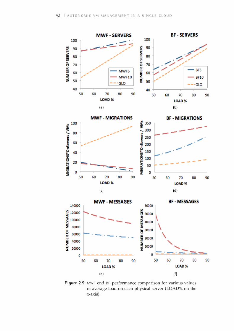
42 autonomic vm management in a single cloud
(a) (b)
(c) (d)
(e) (f)
Figure 2.9: MWF end BF performance comparison for various valuesof average load on each physical server (LOAD% on thex-axis).
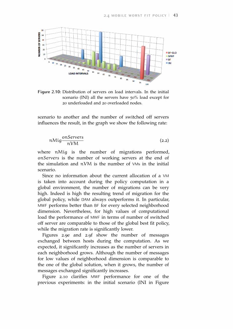
2.4 mobile worst fit policy 43
Figure 2.10: Distribution of servers on load intervals. In the initialscenario (INI) all the servers have 50% load except for20 underloaded and 20 overloaded nodes.
scenario to another and the number of switched off serversinfluences the result, in the graph we show the following rate:
nMigonServers
nVM(2.2)
where nMig is the number of migrations performed,onServers is the number of working servers at the end ofthe simulation and nVM is the number of VMs in the initialscenario.
Since no information about the current allocation of a VMis taken into account during the policy computation in aglobal environment, the number of migrations can be veryhigh. Indeed is high the resulting trend of migration for theglobal policy, while DAM always outperforms it. In particular,MWF performs better than BF for every selected neighborhooddimension. Nevertheless, for high values of computationalload the performance of MWF in terms of number of switchedoff server are comparable to those of the global best fit policy,while the migration rate is significantly lower.
Figures 2.9e and 2.9f show the number of messagesexchanged between hosts during the computation. As weexpected, it significantly increases as the number of servers ineach neighborhood grows. Although the number of messagesfor low values of neighborhood dimension is comparable tothe one of the global solution, when it grows, the number ofmessages exchanged significantly increases.
Figure 2.10 clarifies MWF performance for one of theprevious experiments: in the initial scenario (INI in Figure
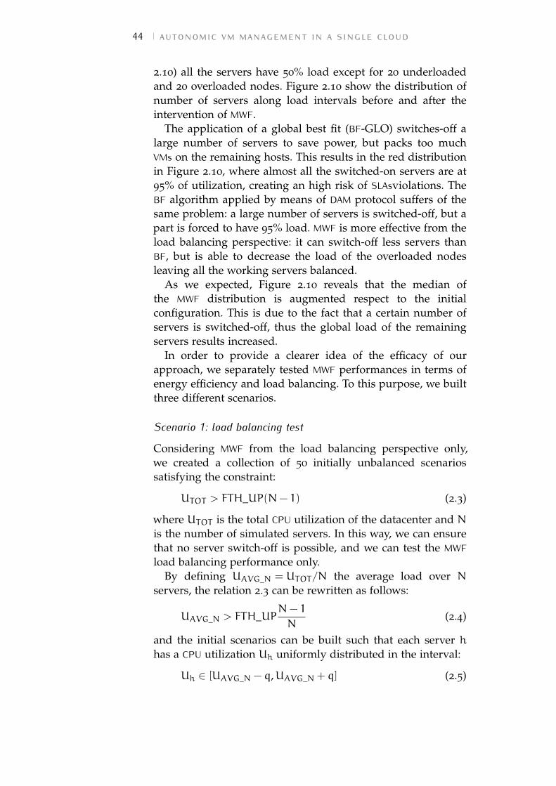
44 autonomic vm management in a single cloud
2.10) all the servers have 50% load except for 20 underloadedand 20 overloaded nodes. Figure 2.10 show the distribution ofnumber of servers along load intervals before and after theintervention of MWF.
The application of a global best fit (BF-GLO) switches-off alarge number of servers to save power, but packs too muchVMs on the remaining hosts. This results in the red distributionin Figure 2.10, where almost all the switched-on servers are at95% of utilization, creating an high risk of SLAsviolations. TheBF algorithm applied by means of DAM protocol suffers of thesame problem: a large number of servers is switched-off, but apart is forced to have 95% load. MWF is more effective from theload balancing perspective: it can switch-off less servers thanBF, but is able to decrease the load of the overloaded nodesleaving all the working servers balanced.
As we expected, Figure 2.10 reveals that the median ofthe MWF distribution is augmented respect to the initialconfiguration. This is due to the fact that a certain number ofservers is switched-off, thus the global load of the remainingservers results increased.
In order to provide a clearer idea of the efficacy of ourapproach, we separately tested MWF performances in terms ofenergy efficiency and load balancing. To this purpose, we builtthree different scenarios.
Scenario 1: load balancing test
Considering MWF from the load balancing perspective only,we created a collection of 50 initially unbalanced scenariossatisfying the constraint:
UTOT > FTH_UP(N− 1) (2.3)
where UTOT is the total CPU utilization of the datacenter and Nis the number of simulated servers. In this way, we can ensurethat no server switch-off is possible, and we can test the MWFload balancing performance only.
By defining UAVG_N = UTOT/N the average load over Nservers, the relation 2.3 can be rewritten as follows:
UAVG_N > FTH_UPN− 1
N(2.4)
and the initial scenarios can be built such that each server hhas a CPU utilization Uh uniformly distributed in the interval:
Uh ∈ [UAVG_N − q,UAVG_N + q] (2.5)
2.4 mobile worst fit policy 45
Figure 2.11: Distribution of servers on load intervals. In the initialscenario (INI) all the servers are on average loadedaround the value of FTH_UP.
where q expresses the degree of imbalance in the initialscenario. We tested the MWF performance with FTH_UP = 90%,q = 10% and averaged the results over 50 simulations.
In each scenario the topology of the neighborhoods isgenerated randomly.
Figure 2.11 shows the distribution of servers over loadintervals. In the initial scenario (INI) all the servers are onaverage loaded around the value of FTH_UP. We show thedistribution after a global WF optimization (WF-GLO in Figure2.11) and the application of MWF by means of DAM protocolwith 10 as neighborhood size.
MWF shows good performance from the load balancingperspective even if, as we expected, relying on a globalknowledge of status of each server, the centralized applicationof a worst fit policy clearly outperforms the distributedapproach.
Scenario 2: power saving test
In order to mainly test the energy saving performance of MWF,we create a collection of scenarios satisfying this constraint:
UTOT = FTH_UP ·M, s.t.M < N (2.6)
where M is the number of servers that remains switched-on atthe end of the optimization. Relation (2.6) can be rewritten asfollows:
UAVG_N = FTH_UP ·MN
(2.7)
46 autonomic vm management in a single cloud
Therefore, given a certain UAVG_N we can calculate theminimum number Mopt of servers that can execute thedatacenter’s workload:
Mopt =UAVG_N ·MFTH_UP
(2.8)
We create a collection of scenarios with increasing values ofUAVG_N, having the load Uh of each server again uniformlydistributed in the interval (2.5) and q = 20%, and we use Mopt
to evaluate the performance of MWF.Figures 2.12a, 2.12b and 2.12c show the number m of
working servers at the end of different MWF distributedexecutions. These values are compared to the minimumpossible number Mopt of running servers in each scenario.
Each point in the graphs of Figure 2.12 represents an initialscenario with different value for UAVG_N.
We repeated the experiment with three different values ofthe rate q/t. Figure 2.12a shows the energy saving performancewith q = 15% of imbalance in the initial scenario and t = 5%as MWF tolerance interval. The number of switched-off serversis far from the optimum value (expressed by the blu line)for every generated scenario, while decreasing the ratio q/tto 20/5 and 20/3 (as reported by Figures 2.12b and 2.12c) theperformance of MWF significantly increases.
For low values of UAVG_N the algorithm seems to performsignificantly better for every value of the rate q/t, Thiseffect is due to the FTH_DOWN, which is fixed at 25%in every scenario and can therefore contribute to makesome MasterClients start if the hosts are detected to beunderloaded (Uh < FTH_DOWN).
Scenario 3: scalability test
In order to test the scalability of the distributed approach,we analyzed MWF behavior while increasing the number ofsimulated servers and VMs up to 2000 and 60000, respectively.Figure 2.13a shows the number of migrations stated by MWFand compare it with that of WF-GLO policy.
Since the number of VMs increases with the number of hosts,we actually compare the ratio between migrations and numberof VMs in the scenario.
WF-GLO policies does not take into account the currentallocation while performing the optimization, therefore, itresults in a very high number of migrations, near to the total
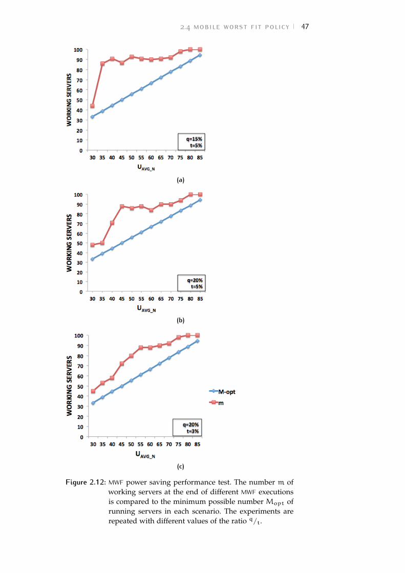
2.4 mobile worst fit policy 47
(a)
(b)
(c)
Figure 2.12: MWF power saving performance test. The number m ofworking servers at the end of different MWF executionsis compared to the minimum possible number Mopt ofrunning servers in each scenario. The experiments arerepeated with different values of the ratio q/t.
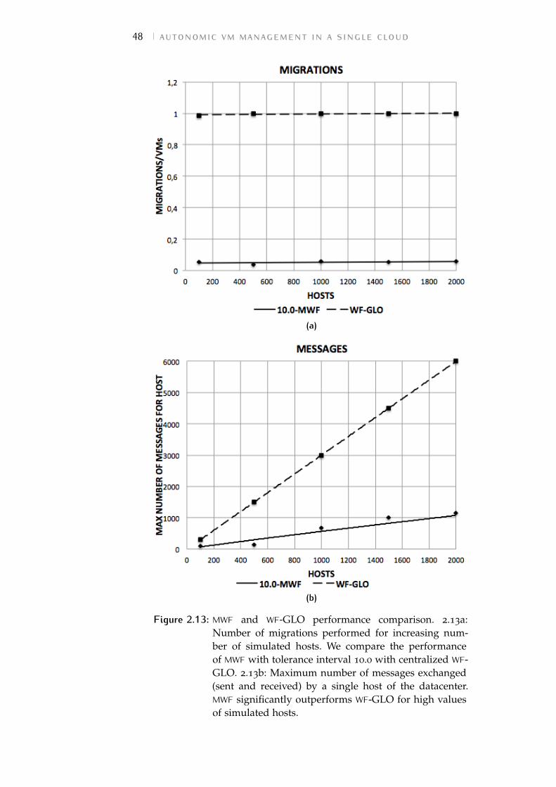
48 autonomic vm management in a single cloud
(a)
(b)
Figure 2.13: MWF and WF-GLO performance comparison. 2.13a:Number of migrations performed for increasing num-ber of simulated hosts. We compare the performanceof MWF with tolerance interval 10.0 with centralized WF-GLO. 2.13b: Maximum number of messages exchanged(sent and received) by a single host of the datacenter.MWF significantly outperforms WF-GLO for high valuesof simulated hosts.
2.5 conclusions and future work 49
of VMs. Conversely, MWF distributed policy only operates onunderloaded or overloaded nodes (with CPU utilization lowerthan FTH_DOWN or higher than FTH_UP, respectively) oron those hosts that are unbalanced in respect to the averageof their neighborhood (CPU utilization out of the interval[MTH_DOWN,MTH_UP]). For this reason, as shown in Figure2.13a, the number of resulting migrations is significantly lowerfor MWF.
In Figure 2.13b, we consider the maximum number ofmessages exchanged by a single host. Since WF-GLO iscentralized, the coordinator node must collect the state of allthe other nodes before starting the optimization and finallyreturn the new configuration to each node. Therefore, asshown in Figure 2.13b, the number of messages exchangedby the coordinator is always proportional to the numberof the nodes it manages. The behavior of MWF policy isagain proportional to the number of nodes but the trends issignificantly lower. This comes from the fact that, according toMWF, each node of the datacenter always communicate with apredefined number of neighbors (5 in this simulation).
Therefore, considering the maximum number of messagesexchanged by a node, for high values of simulated hosts, wecan conclude that MWF distributed approach performs betterthan the centralized WF-GLO algorithm.
2.5 conclusions and future workWe contributed to the autonomic VM management fieldby presenting a decentralized solution for cloud virtualinfrastructure management (DAM), in which the hosts of thedatacenter are able to self-organize and reach a global VMreallocation plan according to a given policy. Relying on DAMprotocol, we investigated two VM migration approaches (MBand MWF) suitable for a distributed management in a clouddatacenter.
We tested MB and MWF behaviors by means of DAM-Simsimulator. The policies show good performance for variousdata centers dimensions in terms of both number of migrationsrequested and maximum number of messages exchanged bya single host. Therefore, we can assert that the decentralizednature of our approach can intrinsically contribute to increasethe scalability of the cloud management infrastructure.
50 autonomic vm management in a single cloud
MB is also able to achieve an appreciable load balancingamong working servers, even if, as we expected, the distributedMB policy cannot outperform a centralized global worst-fitpolicy.
MWF inherits from MB the good load balancing performance,while still some work remain to do to decrease the totalnumber of messages exchanged.
As we expected, the distributed MWF policy cannotoutperform a centralized global best-fit policy (especiallyin terms of number of switched-off hosts and exchangedmessages), but further investigations of performance onincreasing size datacenters has shown that the decentralizednature of our approach can intrinsically contribute to augmentthe scalability of the cloud management infrastructure.
The current version of DAM-Sim is not able to cover all theaspects of real cloud data centers: it can only simulate CPUresources and is not able to derive the optimal neighborhoodstructure from a real cloud network. Since our approachbenefits from a richly connected data center, a possible futurework could be the automatic definition of neighborhoods overa VL2 network [53], while DAM-Sim needs to be extended inorder to take into account not only computational resources,but also memory and bandwidth requirements. This will allowus to test different and more elaborated reallocation policies.We also need to introduce variations of VM load requests atsimulation time to better mirror real datacenter environments.
Further investigation will be necessary to address issuescaused by message losses: the algorithm needs a recoverystrategy to avoid the physical servers never-ending blockedwhile they wait for "unlock" messages.
Finally, since the simulator can only represent a snap-shot ofthe datacenter workload, it must be extended in order to applythe distributed policy to a dynamically changing scenario andmake a benchmark comparison of our approach focusing ontime performance. At latter stage, the frequency of variationsin VM load requests will be increased to better mirror realdatacenter environments.
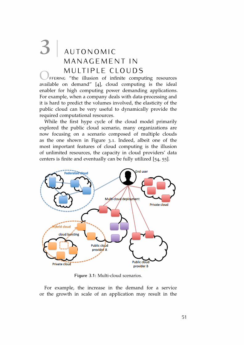
3 A U TO N O M I CM A N A G E M E N T I NM U LT I P L E C LO U D SOffering “the illusion of infinite computing resources
available on demand” [4], cloud computing is the idealenabler for high computing power demanding applications.For example, when a company deals with data-processing andit is hard to predict the volumes involved, the elasticity of thepublic cloud can be very useful to dynamically provide therequired computational resources.
While the first hype cycle of the cloud model primarilyexplored the public cloud scenario, many organizations arenow focusing on a scenario composed of multiple cloudsas the one shown in Figure 3.1. Indeed, albeit one of themost important features of cloud computing is the illusionof unlimited resources, the capacity in cloud providers’ datacenters is finite and eventually can be fully utilized [54, 55].
Figure 3.1: Multi-cloud scenarios.
For example, the increase in the demand for a serviceor the growth in scale of an application may result in the
51
52 autonomic management in multiple clouds
need for additional capacity in the data center. Since actualresource utilization of many real-world application servicesvary unpredictably with time, a single cloud provider maybe overburden by unexpected load leading to unreliable andinterrupted services [1]. In order to handle this issue, awidespread choice by cloud providers is the overprovisioningof data center capacity. That is, maintain the computinginfrastructure several times bigger than the average demandof the system, even if this strategy can lead to a waste ofresources and consequently large expenses for cloud owners.
Conversely, if cloud providers were able to dynamicallyscale up or down their data center capacity relaying oninteroperation of the clouds, they could overcome this issuesaving a substantial amount of money. Cloud interoperabilitycan help to handle the peak-load of services on the cloudthrough resource sharing, avoiding the cost of provisioningand administration of any additional hardware[10].
Public cloud providers usually relay on large scale datacenters and can therefore easily give the perception ofunlimited resources. In this scenario, one may argue thatcloud providers never need immediate external additionalcapacity. However, this assumption does not hold in case ofsmall-size private clouds and for those applications requiringexpansion across geographically distributed resources to meetQoS requirements of their users [56].
Another important motivation for cloud interoperability isthe necessity to improve availability, which is a key feature ofcloud services. In fact, unexpected failures are always possibleand can easily result in service interruption in a single cloudsystem, while a multiple cloud infrastructure can implementflexible mechanisms to relocate resources and continue thedelivery of guaranteed service levels. If the physical allocation(on a specific cloud) of the application-level services is nottransparent to the cutomers, this knowledge can also be usedto intentionally build multiple cloud deployments in order toimprove the availability and disaster recovery capabilities.
Furthermore, in order to meet the low-latency accessrequirement of some applications, a single cloud providershould have a data center in all geographic locations of theworld. This is highly unlikely to happen but cloud federationcan provide a similar solution allowing the cloud systems tocomplement each other by sharing their resources. As pointedout by Toosi et al. [1], “utilizing multiple clouds at the same
autonomic management in multiple clouds 53
time is the only solution for satisfying the requirements ofthe geographically dispersed service consumers who requirefast response time”. Nevertheless, in this scenario, a furthermechanism to dynamically coordinate load distribution amongdifferent cloud data centers is required. As some customershave specific restrictions about the legal boundaries in whichtheir data can be hosted, cloud interoperability could alsorepresent an opportunity for the provider to identify otherproviders able to meet the regulations due to the location oftheir data centers [1].
Finally, cloud interoperability can give a further improve-ment to the Green Computing area. The necessity to saveenergy by avoiding the problem of the idle capacity withoutlosing the capability to respond to peaks in demand, can bemanaged through the leasing of underutilized computationalpower or on-demand purchasing additional resources fromother providers. In this way, we would experience an overallincrease in the efficiency of resource utilization.
In the following chapters, we consider – as a case study– the execution of data-intensive applications over multipleclouds. Indeed, the exponential increase in the use of mobiledevices, the wide-spread employment of sensors across variousdomains and, in general, the trending evolution towards theInternet of things, is constantly creating large volumes of datathat must be processed to extract knowledge. This pressingneed for fast analysis of large amount of data calls the attentionof the research community and fosters new challenges in thebig data research area [57]. Since data-intensive applicationsare usually costly – in terms of CPU and memory utilization–, and often require the execution to satisfy constraintssuch as deadlines or reliability, facing huge and sometimesunpredictable amounts of input data, a lot of work hasbeen done to simplify the distribution of computational loadamong several physical or virtual nodes and take advantage ofparallelism.
For example, MapReduce [58] programming model andits popular open-source implementation Apache Hadoop [59]allow to transparently partition the input data-set into anarbitrary number of parts, each exclusively processed by adifferent computing node. Nevertheless, the fulfilling of agiven time constraint requires a high degree of elasticity inresource provisioning: if an unexpected data peak appears, it isnecessary to quickly provide additional computing resources
54 autonomic management in multiple clouds
to maintain the execution time within the given deadline. Inthis scenario, a widespread choice is to relay on a cloudinfrastructure to take advantage of its elasticity in virtualresource provisioning. Furthermore, the on-premise (company-owned) cloud can be combined with the resources of anoff-premise (owned by a third party provider) cloud to furtherimprove the elasticity of the virtual infrastructure. Indeed,many organizations are now focusing on a multiple cloudscenario to enable the execution of data-intensive applicationsand, in general, to take advantage of the numerous benefitsthat cloud interoperability can bring to both cloud providerand customer.
In the following, we mainly focus on the enhancements thatcloud interoperability can bring to the big data research areaif coupled with the autonomic ability to scale-up/-down thecomputing infrastructure when the resource demand changes.We firstly provide a classification of the cloud interoperabilityscenarios and a overview of main existing contributionsto enable data-intensive computation over multiple clouds(Chapter 3.1). Later (Chapters 3.2 and 3.3), we describe oursolution as well as the leveraged infrastructure and application-level tools. In Chapter 3.4, 3.5 and 3.6 we describe the adoptedapproaches in detail by focusing on the policies and models toenable MapReduce in multi-cloud environments. We provideour conclusions and a vision of possible evolutions of theworks in this field in Chapter 3.7.
3.1 positioning our contributionAs integration and aggregation of cloud services have recentlyreceived the attention of the research community, severaldifferent terms have been used to define cloud interoperability.A precise understanding of these terms and definitions,including differences and similarities, clarifies the position ofour contribution.
The term Inter-cloud has been introduced by Cisco [60] as aninterconnected global “cloud of clouds” that recalls the knownterm Internet, “network of networks”. The Inter-cloud refers toa mesh of clouds that are unified by open standard protocolsto provide a cloud interoperability. The Inter-cloud final goal isto create a web of computing element ubiquitously connected
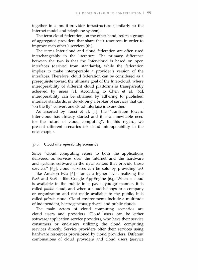
3.1 positioning our contribution 55
together in a multi-provider infrastructure (similarly to theInternet model and telephone system).
The term cloud federation, on the other hand, refers a groupof aggregated providers that share their resources in order toimprove each other’s services [61].
The terms Inter-cloud and cloud federation are often usedinterchangeably in the literature. The primary differencebetween the two is that the Inter-cloud is based on openinterfaces (derived from standards), while the federationimplies to make interoperable a provider’s version of theinterfaces. Therefore, cloud federation can be considered as aprerequisite toward the ultimate goal of the Inter-cloud, whereinteroperability of different cloud platforms is transparentlyachieved by users [1]. According to Chen et al. [62],interoperability can be obtained by adhering to publishedinterface standards, or developing a broker of services that can“on the fly” convert one cloud interface into another.
As asserted by Toosi et al. [1], the “transition towardInter-cloud has already started and it is an inevitable needfor the future of cloud computing”. In this regard, wepresent different scenarios for cloud interoperability in thenext chapter.
3.1.1 Cloud interoperability scenarios
Since “cloud computing refers to both the applicationsdelivered as services over the internet and the hardwareand systems software in the data centers that provide thoseservices” [63], cloud services can be sold by providing IaaS– like Amazon EC2 [6] – or at a higher level, realizing thePaaS and SaaS – like Google AppEngine [64]. When a cloudis available to the public in a pay-as-you-go manner, it iscalled public cloud, and when a cloud belongs to a companyor organization and not made available to the public, it iscalled private cloud. Cloud environments include a multitudeof independent, heterogeneous, private, and public clouds.
The main actors of cloud computing scenarios arecloud users and providers. Cloud users can be eithersoftware/application service providers, who have their serviceconsumers or end-users utilizing the cloud computingservices directly. Service providers offer their services usinghardware resources provisioned by cloud providers. Differentcombinations of cloud providers and cloud users (service
56 autonomic management in multiple clouds
Figure 3.2: Classification of interoperability solutions for clouds assuggested in the work by Toosi et al [1]. This dissertationmainly focus on solutions to enable the hybrid cloud sce-nario in grey.
providers or end-users) give rise to several plausible use casesbetween clouds [65]:
• if cloud interconnection is performed at different levels ofcloud stack layers, for example, a PaaS and IaaS provider,the scenario is often referred as delegation or verticalfederation;• if interconnection between clouds is at the same layer
(e.g., IaaS to IaaS), it is called horizontal federation.
As pointed out by Villegas et al. [66], a federated cloudstructure is a vertical stack analogous to the layered cloudservice model. At each layer, a service request can be servedeither through local resources using delegation or by a partnercloud provider through federation.
An exhaustive classification of the different scenarios ofcloud interoperation can be found in [1]. According to thisclassification, if cloud interoperability is realized by cloudproviders, who adopt and implement standard interfaces,protocols, formats, and architectural components to facilitatecollaboration, we have a provider-centric interoperability.Provider-centric scenarios are categorized as hybrid andfederated cloud scenarios (as depicted in Figure 3.2). Onthe contrary, client-centric interoperability is not supportedby cloud providers. The customers are required to initiateit by themselves or via third-party brokers. This kind ofinteroperability does not require an a priori business agreementamong cloud providers and allows multiple cloud scenarioswithout (or with minimal) adoption of common interfaces and
3.1 positioning our contribution 57
protocols[1]. We consider multicloud and aggregated service bybroker as client-centric interoperability scenarios.
In multicloud scenario in particular, the customers areresponsible for the management of resources across multipleclouds. Service deployment, negotiation, and monitoring ofeach cloud provider during service operation are performedby end-user applications. In this case, the use of an adapterlibrary with different APIs to run services on different clouds isrequired.
In aggregated service by broker scenario, a new actor, the broker,aggregates services from multiple cloud providers and offersto the final customers an integrated single entry point to theservices. In this way, from the point of view of the customer anabstraction layer is created for the management of componentsdeployed on different clouds.
The federated cloud scenario is a case of provider-centricapproach to interoperability. Here, a group of cloud providersare federated and trade their surplus resources among eachother to gain economies of scale and a higher level of efficiency.Therefore, the customer establishes a contract with a cloudprovider that is a member of a federation, and the computingutility is delivered to him using resources of either one cloudprovider or a combination of different cloud providers. Thecustomer might be aware or unaware of the federation and hiscontract is with a single cloud provider.
In hybrid cloud architectures, an organization that ownsits private cloud moves part of its virtual infrastructure toexternal cloud providers. This extension of a private cloud tocombine local resources with those of a remote off-premisecloud allows the end-user applications to scale-up (cloudburst) through public clouds when the local infrastructureis insufficient. When the emergency is solved the customercan scale the application back down in the private cloudto minimize the cost of the public infrastructure utilization.Furthermore, this scenario can be extended if the organizationoffers capacity from its private cloud to others when thatcapacity is not needed for internal operations. In fact, assuggested by the overlapping areas in Figure 3.2, federatedand hybrid scenario shows common aspects from the point ofview of the technologies to enable interoperation.
In the following, we focus on the hybrid cloud model as amethod to overcome the limits of a single on-premise cloud
58 autonomic management in multiple clouds
infrastructure when dealing with heavy computing tasks suchas data-intensive applications.
3.1.2 Enabling data-intensive applications over multiple clouds
MapReduce programming model is a widespread choice whendealing with data-intensive tasks because it simplifies theimplementation of distributed application for data processing.According to this approach, the user must specify twofunctions: the mapper and the reducer. The mapper extracts fromthe given input data a series of intermediate key/value pairs,while the reducer merges all the intermediate values associatedwith the same key. The programs implemented accordingto this model can be automatically parallelized and easilyexecuted on a distributed infrastructure [58].
MapReduce model is implemented and supported by severalplatforms [59, 67–69]. In this work, we opted for ApacheHadoop [59], one of the most used and popular frameworksfor distributed computing.
MapReduce success is primarily due to its simpleparallelization model, graceful degradation in case of partialsystem failures and good horizontal scalability. Nevertheless,data-intensive applications require a high degree of elasticityto deal with unpredictable data peaks or execution deadlines.This requirement has inevitably directed the attentionof the big data research area towards the cloud. Inparticular, combining both on-premise and off-premise cloudinfrastructures, the hybrid scenario is the ideal enabler fordata-intensive applications. The rationale behind employinga hybrid approach can be manyfold, e.g. using off-premiseresources for being able to guarantee a minimum QoS,satisfying a predefined deadline constraint, or partitioning thecomputation between on- and off-premise zones as mandatedby security compliance requirement (for instance, if part of thedata is not allowed to cross the boundary of the on-premiseinfrastructure).
In fact, among the various widely used and trendingplatforms that leverage the hybrid cloud delivery model[70, 71], data-intensive analytics at large scale is one of themost challenging cases, especially when large volumes of dataare involved.
Conventional big data analytics frameworks – such asHadoop [59] – assume physical co-location of IT resources with
3.1 positioning our contribution 59
high-speed interconnection among servers. This assumptionis lifted in hybrid cloud environments comprising physicallyseparated datacenters that are interconnected via a networkthat is at least an order of magnitude slower (either dedicatedconnectivity or the open Internet).
Furthermore, due to the size of the data being analyzed,most big data analytics techniques make heavy use of datalocality by shipping the computation close to the data. Thisaspect is particularly challenging when boosting a privatecloud with extra temporary VMs from a public IaaS cloud tofinish a big data analytics job faster: the newly provisionedVMs do not hold any data and as such it is necessary to sendlarge amounts of data over the slow link in order to be able toleverage the extra computational capability.
Therefore, we can claim that data movement is elevated to amajor challenge in hybrid cloud big data analytics.
3.1.3 MapReduce over cloud environments: state of the art
Recently, a lot of work has focused on cloud computingfor the execution of big data applications: as pointed outin [72], the relationship between big data and the cloudis very tight, because collecting and analyzing huge andvariable volumes of data require infrastructures able todynamically adapt their size and their computing power to theapplication needs. For this reason, several efforts to improvethe MapReduce performance leverage cloud technologies[73–76], with the assumption of having unlimited computingresources. These efforts are complemented by works onstorage elasticity [77, 78], which explore how to deal withthe explosion of the costs related to the storage capacity andthe Input/Output (I/O) bandwidth, and are highly relevant forMapReduce applications.
The work by Chen et al. [79] presents an accurate model foroptimal resource provisioning useful to operate MapReduceapplications in public clouds. Similarly, Palanisamy et al.[80] deal with optimizing the allocation of VMs executingMapReduce jobs in order to minimize the infrastructure cost ina cloud datacenter. In the same single-cloud scenario, Rizvandiet al. [81] focus on the automatic estimation of MapReduceconfiguration parameters, while Verma et al. [82] propose aresource allocation algorithm able to estimate the amount ofresources required to meet MapReduce-specific performance
60 autonomic management in multiple clouds
goals. However, these models assume an unlimited amountof available resources (as in the classic public cloud) and arenot intended to address the challenges of the hybrid cloudscenario, which is the target environment of our work.
According to the classification in [1], our work mainly dealswith the hybrid cloud approach for cloud interoperability,because the main motivation of our system is to allow cloudbursting to EC. However, our proposal could also be classifiedas a Federation mechanism for cloud aggregation because –as in federated clouds – the interoperation between clouds iscompletely transparent to end-users.
The choice of primarily relay on a small (e.g., private) cloudand then use the extra-capacity offered by a public cloudfor opportunistic scale-out has been investigated by severalauthors in the past [83, 84].
The work in [85] and [86] focus on enabling cloud burstingthrough inter-cloud migration of VMs, which is generally atime and resource expensive mechanism. The system describedin [86], in particular, optimizes the overhead of migrationusing an intelligent pre-copying mechanisms that proactivelyreplicates VMs before the migration. Our work doesn’t takeinto consideration the VM migration, but only dynamicinstantiation of new compute nodes on EC, thus to avoidthe unnecessary movement of the whole VM snapshot acrossthe cloud boundaries. This technique is particularly suitablefor the MapReduce model because the Hadoop provisioningand decommissioning mechanism intrinsically contributes tosimplify the cloud bursting process.
The hybrid scenario is also investigated in the works byZhang et al. [70, 87] by focusing on the workload factoringand management across federated clouds. More similarly toour approach, cloud bursting techniques has been adoptedfor scaling MapReduce applications in the work by Mattesset al. [88], which presents an online provisioning policy tomeet a deadline for the Map phase. Differently from ourapproach, [88] only focuses on the prediction of the executiontime for the map phase but does not take into account theresource utilization, nor provides an autonomic mechanismto reconfigure the cluster if a future deadline exceeding ispredicted. Furthermore, [88] relies on the assumption that thedistributed filesystem is persistently deployed and loaded withdata throughout the execution of MapReduce workloads. Assuch, it does not capture the initial phase of cross-cloud data
3.1 positioning our contribution 61
distribution and data-balancing, a vital phase in high valuehybrid cloud use cases, such as cloud-bursting.
Also the work presented by Kailasam et al. [89] dealswith cloud bursting for big data applications. It proposes anextension of the MapReduce model to avoid the shortcomingsof high latencies in inter-cloud data transfer: the computationinside IC follows the batch MapReduce model, while inEC a stream processing platform called Storm is used. Theresulting system shows significant benefits. Differently from[89], we chose to keep complete transparency and uniformitywith respect to the allocation of working nodes and theirconfiguration.
Several recent efforts are focused on improving the perfor-mance of MapReduce frameworks for hybrid environments.HybridMR [90] proposes a solution for executing MapReducein a hybrid desktop grids and external voluntary nodes, butdoes not consider expanding and shrinking a MapReducesetup dynamically. HadoopDB [91] proposes a a hybrid systemcomprising Hadoop and parallel database systems to yield theresilience, and scalability of Hadoop and the performance andefficiency of parallel databases. Similarly, hybrid schedulingtechniques [92–94] uses GPUs to improve the performance ofMapReduce applications in accelerator-enabled clusters. Thesetechniques uses hybrid computing to improve the performanceof MapReduce applications, but the hybrid aspect is on thecomputational side rather than the networking side.
Specifically to workload performance prediction andoptimization in hybrid clouds, Van den Bossche et al. [95]have proposed a linear/integer programming model forrelevant workloads, showing substantial improvement overnaive executions. Albeit valuable from a bounds perspective,such models are typically hard to scale and also fail to captureframework-specific intricacies, such as data-movement anddata locality. Imai et al. [96] explore hybrid cloud predictionpatterns from the perspective of selection of resource units(VM sizing types) with prediction techniques. This work couldbe used to enrich the performance of our proposed models(depicted in Chapters 3.3 and 3.6) by selecting matching VMsizes for hosting MapReduce daemons.
The fallowing tables (3.1, 3.2 and 3.3) summarize the mainfeatures of the referred works in the field of VM managementover multiple-clouds. Table 3.4 refers to our contributionspresented in the next section.
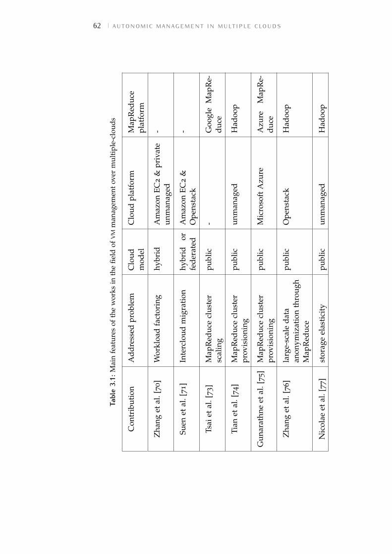
62 autonomic management in multiple clouds
Tabl
e3.
1:M
ain
feat
ures
ofth
ew
orks
inth
efie
ldof
VMm
anag
emen
tov
erm
ulti
ple-
clou
ds
Con
trib
utio
nA
ddre
ssed
prob
lem
Clo
udm
odel
Clo
udpl
atfo
rmM
apR
educ
epl
atfo
rm
Zha
nget
al.[
70]
Wor
kloa
dfa
ctor
ing
hybr
idA
maz
onEC
2&
priv
ate
unm
anag
ed-
Suen
etal
.[71]
Inte
rclo
udm
igra
tion
hybr
idor
fede
rate
dA
maz
onEC
2&
Ope
nsta
ck-
Tsai
etal
.[73
]M
apR
educ
ecl
uste
rsc
alin
gpu
blic
-G
oogl
eM
apR
e-du
ce
Tian
etal
.[74]
Map
Red
uce
clus
ter
prov
isio
ning
publ
icun
man
aged
Had
oop
Gun
arat
hne
etal
.[75]
Map
Red
uce
clus
ter
prov
isio
ning
publ
icM
icro
soft
Azu
reA
zure
Map
Re-
duce
Zha
nget
al.[
76]
larg
e-sc
ale
data
anon
ymiz
atio
nth
roug
hM
apR
educ
e
publ
icO
pens
tack
Had
oop
Nic
olae
etal
.[77]
stor
age
elas
tici
typu
blic
unm
anag
edH
adoo
p
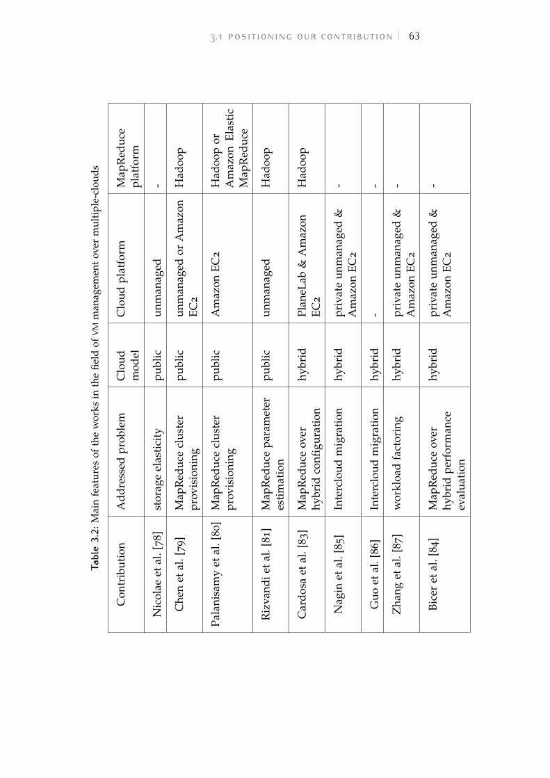
3.1 positioning our contribution 63
Tabl
e3.
2:M
ain
feat
ures
ofth
ew
orks
inth
efie
ldof
VMm
anag
emen
tov
erm
ulti
ple-
clou
ds
Con
trib
utio
nA
ddre
ssed
prob
lem
Clo
udm
odel
Clo
udpl
atfo
rmM
apR
educ
epl
atfo
rm
Nic
olae
etal
.[78]
stor
age
elas
tici
typu
blic
unm
anag
ed-
Che
net
al.[
79]
Map
Red
uce
clus
ter
prov
isio
ning
publ
icun
man
aged
orA
maz
onEC
2
Had
oop
Pala
nisa
my
etal
.[80]
Map
Red
uce
clus
ter
prov
isio
ning
publ
icA
maz
onEC
2H
adoo
por
Am
azon
Elas
tic
Map
Red
uce
Riz
vand
iet
al.[
81]
Map
Red
uce
para
met
eres
tim
atio
npu
blic
unm
anag
edH
adoo
p
Car
dosa
etal
.[83]
Map
Red
uce
over
hybr
idco
nfigu
rati
onhy
brid
Plan
eLab
&A
maz
onEC
2
Had
oop
Nag
inet
al.[
85
]In
terc
loud
mig
rati
onhy
brid
priv
ate
unm
anag
ed&
Am
azon
EC2
-
Guo
etal
.[86
]In
terc
loud
mig
rati
onhy
brid
--
Zha
nget
al.[
87]
wor
kloa
dfa
ctor
ing
hybr
idpr
ivat
eun
man
aged
&A
maz
onEC
2
-
Bice
ret
al.[
84]
Map
Red
uce
over
hybr
idpe
rfor
man
ceev
alua
tion
hybr
idpr
ivat
eun
man
aged
&A
maz
onEC
2
-
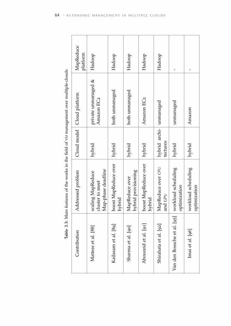
64 autonomic management in multiple clouds
Tabl
e3.
3:M
ain
feat
ures
ofth
ew
orks
inth
efie
ldof
VMm
anag
emen
tov
erm
ulti
ple-
clou
ds
Con
trib
utio
nA
ddre
ssed
prob
lem
Clo
udm
odel
Clo
udpl
atfo
rmM
apR
educ
epl
atfo
rm
Mat
tess
etal
.[88]
scal
ing
Map
Red
uce
clus
ter
tom
eet
Map
-pha
sede
adlin
e
hybr
idpr
ivat
eun
man
aged
&A
maz
onEC
2
Had
oop
Kai
lasa
met
al.[
89
]bo
ost
Map
Red
uce
over
hybr
idhy
brid
both
unm
anag
edH
adoo
p
Shar
ma
etal
.[90
]M
apR
educ
eov
erhy
brid
prov
isio
ning
hybr
idbo
thun
man
aged
Had
oop
Abo
uzei
det
al.[
91]
boos
tM
apR
educ
eov
erhy
brid
hybr
idA
maz
onEC
2H
adoo
p
Shir
ahat
aet
al.[
92]
Map
Red
uce
over
CPU
and
GPU
hybr
idar
chi-
tect
ures
unm
anag
edH
adoo
p
Van
den
Boss
che
etal
.[95]
wor
kloa
dsc
hedu
ling
opti
miz
atio
nhy
brid
unm
anag
ed-
Imai
etal
.[96]
wor
kloa
dsc
hedu
ling
opti
miz
atio
nhy
brid
Am
azon
-
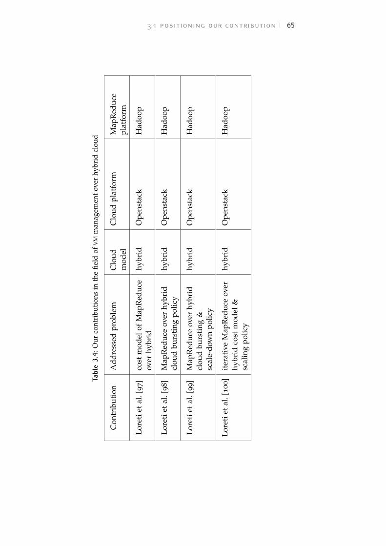
3.1 positioning our contribution 65
Tabl
e3.
4:O
urco
ntri
buti
ons
inth
efie
ldof
VMm
anag
emen
tov
erhy
brid
clou
d
Con
trib
utio
nA
ddre
ssed
prob
lem
Clo
udm
odel
Clo
udpl
atfo
rmM
apR
educ
epl
atfo
rm
Lore
tiet
al.[
97
]co
stm
odel
ofM
apR
educ
eov
erhy
brid
hybr
idO
pens
tack
Had
oop
Lore
tiet
al.[
98
]M
apR
educ
eov
erhy
brid
clou
dbu
rsti
ngpo
licy
hybr
idO
pens
tack
Had
oop
Lore
tiet
al.[
99
]M
apR
educ
eov
erhy
brid
clou
dbu
rsti
ng&
scal
e-do
wn
polic
y
hybr
idO
pens
tack
Had
oop
Lore
tiet
al.[
100]
iter
ativ
eM
apR
educ
eov
erhy
brid
cost
mod
el&
scal
ing
polic
y
hybr
idO
pens
tack
Had
oop
66 autonomic management in multiple clouds
3.2 enabling toolsIn order to better clarify our solution for enabling data-processing over the hybrid cloud, we start by introducingthe infrastructure and application level tools we relay on:OpenStack [5] (one of the most popular open-source platformsfor cloud computing) and MapReduce [58] (a programmingmodel for distributed data-intensive applications).
3.2.1 OpenStack architecture
OpenStack [5] is an open-source platform for cloud computingreleased under the terms of the Apache License. It wasdeveloped in 2010 during a project lead by Rackspace incollaboration with NASA. Similarly to other free open-sourceplatforms in this field [101–103], it owes its notoriety not onlyto the economical benefits derived from the open-source licensebut also to the possibility to adapt the solution to specificrequirements. This characteristic is particularly relevant inorder to support the implementation of multi-cloud solutions.Furthermore, as open-source cloud platforms mostly supportstandard interfaces such as Open Grid Forum (OGF) [104]and Open Cloud Computing Interface (OCCI) [105], applicationsdeployed on these architectures can be easily moved from oneIaaS provider to another, without having to be modified [1].
OpenStack currently constitutes the basis of several publicdeployment – e.g., Rackspace public cloud [106], HP Helioncloud [107], etc. – and is extensively used by the researchdepartments of large companies (e.g., IBM), thus revealing thematurity of this open-source product.
Thanks to its modular architecture, OpenStack is particularlyhandful when a customization of the cloud solution is required.It can be configured either to realize a small private cloud orto control large pools of compute, storage, and networkingresources in big data centers. If some functionalities arenot relevant to the considered domain, we can avoid theinstallation and configuration of the correspondent modules,saving disk space and preventing the risk of failures in unusedportions of code.
OpenStack has a centralized architecture composed by asingle cloud machine (the cloud controller) that orchestratesall the physical machines hosting the VMs (the cloud computenodes). In large datacenters, OpenStack can also give support
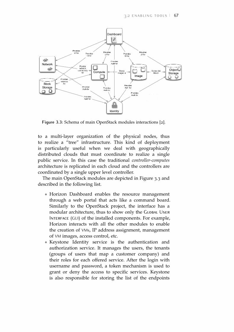
3.2 enabling tools 67
Figure 3.3: Schema of main OpenStack modules interactions [2].
to a multi-layer organization of the physical nodes, thusto realize a “tree” infrastructure. This kind of deploymentis particularly useful when we deal with geographicallydistributed clouds that must coordinate to realize a singlepublic service. In this case the traditional controller-computesarchitecture is replicated in each cloud and the controllers arecoordinated by a single upper level controller.
The main OpenStack modules are depicted in Figure 3.3 anddescribed in the following list.
• Horizon Dashboard enables the resource managementthrough a web portal that acts like a command board.Similarly to the OpenStack project, the interface has amodular architecture, thus to show only the Global UserInterface (GUI) of the installed components. For example,Horizon interacts with all the other modules to enablethe creation of VMs, IP address assignment, managementof VM images, access control, etc.• Keystone Identity service is the authentication and
authorization service. It manages the users, the tenants(groups of users that map a customer company) andtheir roles for each offered service. After the login withusername and password, a token mechanism is used togrant or deny the access to specific services. Keystoneis also responsible for storing the list of the endpoints
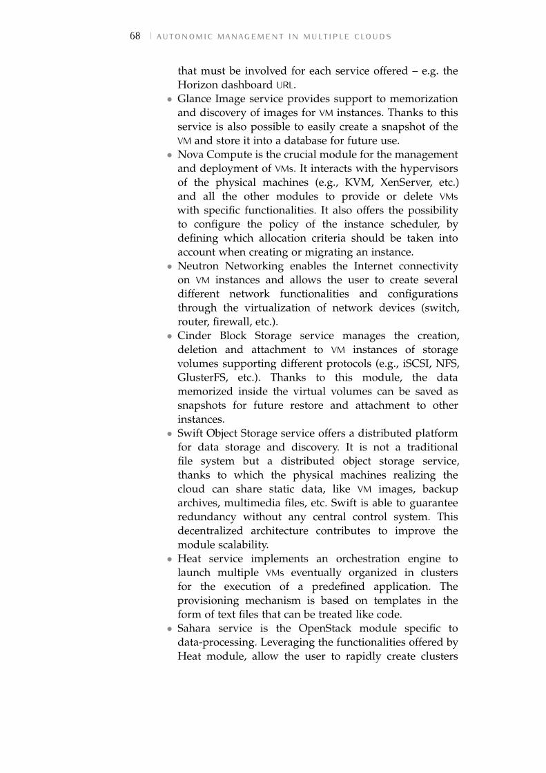
68 autonomic management in multiple clouds
that must be involved for each service offered – e.g. theHorizon dashboard URL.• Glance Image service provides support to memorization
and discovery of images for VM instances. Thanks to thisservice is also possible to easily create a snapshot of theVM and store it into a database for future use.• Nova Compute is the crucial module for the management
and deployment of VMs. It interacts with the hypervisorsof the physical machines (e.g., KVM, XenServer, etc.)and all the other modules to provide or delete VMswith specific functionalities. It also offers the possibilityto configure the policy of the instance scheduler, bydefining which allocation criteria should be taken intoaccount when creating or migrating an instance.• Neutron Networking enables the Internet connectivity
on VM instances and allows the user to create severaldifferent network functionalities and configurationsthrough the virtualization of network devices (switch,router, firewall, etc.).• Cinder Block Storage service manages the creation,
deletion and attachment to VM instances of storagevolumes supporting different protocols (e.g., iSCSI, NFS,GlusterFS, etc.). Thanks to this module, the datamemorized inside the virtual volumes can be saved assnapshots for future restore and attachment to otherinstances.• Swift Object Storage service offers a distributed platform
for data storage and discovery. It is not a traditionalfile system but a distributed object storage service,thanks to which the physical machines realizing thecloud can share static data, like VM images, backuparchives, multimedia files, etc. Swift is able to guaranteeredundancy without any central control system. Thisdecentralized architecture contributes to improve themodule scalability.• Heat service implements an orchestration engine to
launch multiple VMs eventually organized in clustersfor the execution of a predefined application. Theprovisioning mechanism is based on templates in theform of text files that can be treated like code.• Sahara service is the OpenStack module specific to
data-processing. Leveraging the functionalities offered byHeat module, allow the user to rapidly create clusters
3.2 enabling tools 69
of VMs configured to execute various data-intensiveexecution models. It offers the possibility to installseveral MapReduce platforms on the newly providedVMs, easily launch jobs and scale-up/down the virtualinfrastructure at runtime. All these operations can beexecuted by simply using the Horizon interface.• Ceilometer service is a monitoring module. It periodically
checks the utilization of virtual resources and storesthe monitoring information in a specific database forsubsequent retrieval and analysis.
Although not specifically designed for either interoperabilityor portability, OpenStack is very close to being a standardin the cloud ecosystem thanks to its open-source nature andmodular architecture. For these reasons, we chose OpenStackas a base for the implementation of our architecture.
3.2.2 MapReduce theory and implementation
Over the last few years, the big-data research area has gainedimportance thanks to the increase in the use of mobile devicesand the adoption of sensors networks in various fields. Thesetechnologies have created the pressing need for fast analysis oflarge volumes of data. The MapReduce programming model[58] and its open-source implementation through the ApacheHadoop runtime [59] have gained significant traction for thepurpose of enabling data-intensive applications by distributingthe computational load among several servers and takingadvantage of parallelism.
MapReduce principals were firstly enunciated in 2004 in thework by Dean and Ghemawat [108] as a solution to simplifythe execution of data-intensive applications over a collectionof physical servers. Indeed, when the volumes of data to beprocessed are large, even the execution of simple algorithms(e.g. grep, URL access count, inverted index, etc.) can behighly time-consuming. Before the adoption of the MapReducemodel, a popular solution for the problem was to reformulatethe algorithm in a distributed form (i.e., in a form that can beexecuted by multiple servers in a coordinated way), divide anddistribute the input data and, eventually, implement disasterrecovery mechanisms to avoid that failures on a single nodeaffect the whole computation. In these circumstances, even theimplementation of simple algorithms turned into a difficultproblem where concurrency must be carefully managed.
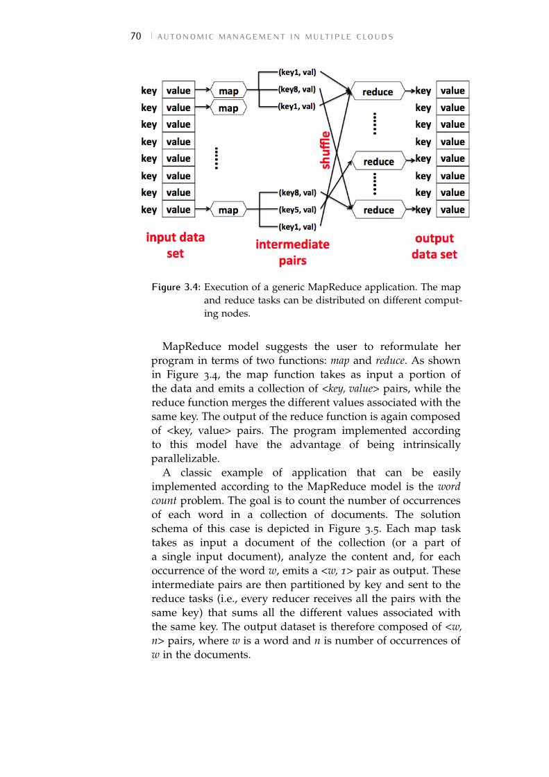
70 autonomic management in multiple clouds
Figure 3.4: Execution of a generic MapReduce application. The mapand reduce tasks can be distributed on different comput-ing nodes.
MapReduce model suggests the user to reformulate herprogram in terms of two functions: map and reduce. As shownin Figure 3.4, the map function takes as input a portion ofthe data and emits a collection of <key, value> pairs, while thereduce function merges the different values associated with thesame key. The output of the reduce function is again composedof <key, value> pairs. The program implemented accordingto this model have the advantage of being intrinsicallyparallelizable.
A classic example of application that can be easilyimplemented according to the MapReduce model is the wordcount problem. The goal is to count the number of occurrencesof each word in a collection of documents. The solutionschema of this case is depicted in Figure 3.5. Each map tasktakes as input a document of the collection (or a part ofa single input document), analyze the content and, for eachoccurrence of the word w, emits a <w, 1> pair as output. Theseintermediate pairs are then partitioned by key and sent to thereduce tasks (i.e., every reducer receives all the pairs with thesame key) that sums all the different values associated withthe same key. The output dataset is therefore composed of <w,n> pairs, where w is a word and n is number of occurrences ofw in the documents.
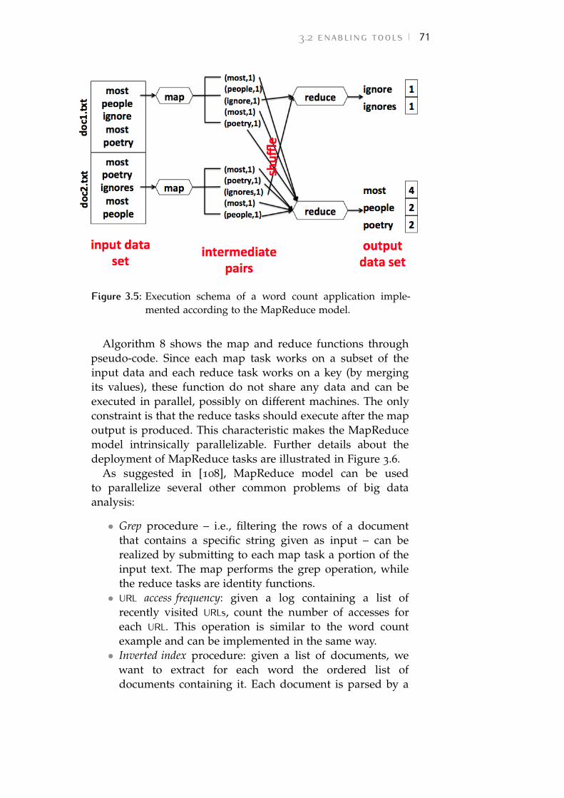
3.2 enabling tools 71
Figure 3.5: Execution schema of a word count application imple-mented according to the MapReduce model.
Algorithm 8 shows the map and reduce functions throughpseudo-code. Since each map task works on a subset of theinput data and each reduce task works on a key (by mergingits values), these function do not share any data and can beexecuted in parallel, possibly on different machines. The onlyconstraint is that the reduce tasks should execute after the mapoutput is produced. This characteristic makes the MapReducemodel intrinsically parallelizable. Further details about thedeployment of MapReduce tasks are illustrated in Figure 3.6.
As suggested in [108], MapReduce model can be usedto parallelize several other common problems of big dataanalysis:
• Grep procedure – i.e., filtering the rows of a documentthat contains a specific string given as input – can berealized by submitting to each map task a portion of theinput text. The map performs the grep operation, whilethe reduce tasks are identity functions.• URL access frequency: given a log containing a list of
recently visited URLs, count the number of accesses foreach URL. This operation is similar to the word countexample and can be implemented in the same way.• Inverted index procedure: given a list of documents, we
want to extract for each word the ordered list ofdocuments containing it. Each document is parsed by a
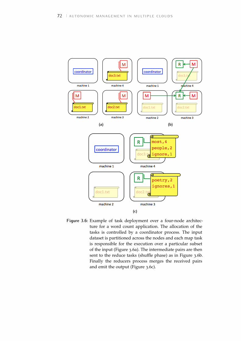
72 autonomic management in multiple clouds
(a) (b)
(c)
Figure 3.6: Example of task deployment over a four-node architec-ture for a word count application. The allocation of thetasks is controlled by a coordinator process. The inputdataset is partitioned across the nodes and each map taskis responsible for the execution over a particular subsetof the input (Figure 3.6a). The intermediate pairs are thensent to the reduce tasks (shuffle phase) as in Figure 3.6b.Finally the reducers process merges the received pairsand emit the output (Figure 3.6c).
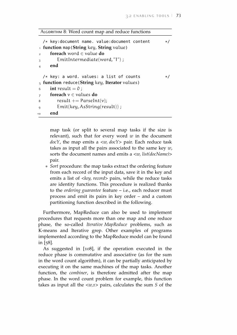
3.2 enabling tools 73
Algorithm 8: Word count map and reduce functions
/* key:document name. value:document content */
1 function map(String key, String value)2 foreach word ∈ value do3 EmitIntermediate(word, "1") ;4 end
/* key: a word. values: a list of counts */
5 function reduce(String key, Iterator values)6 int result = 0 ;7 foreach v ∈ values do8 result += ParseInt(v);9 Emit(key,AsString(result)) ;
10 end
map task (or split to several map tasks if the size isrelevant), such that for every word w in the documentdocY, the map emits a <w, docY> pair. Each reduce tasktakes as input all the pairs associated to the same key w,sorts the document names and emits a <w, list(docName)>pair.• Sort procedure: the map tasks extract the ordering feature
from each record of the input data, save it in the key andemits a list of <key, record> pairs, while the reduce tasksare identity functions. This procedure is realized thanksto the ordering guarantee feature – i.e., each reducer mustprocess and emit its pairs in key order – and a custompartitioning function described in the following.
Furthermore, MapReduce can also be used to implementprocedures that requests more than one map and one reducephase, the so-called Iterative MapReduce problems, such asK-means and Iterative grep. Other examples of programsimplemented according to the MapReduce model can be foundin [58].
As suggested in [108], if the operation executed in thereduce phase is commutative and associative (as for the sumin the word count algorithm), it can be partially anticipated byexecuting it on the same machines of the map tasks. Anotherfunction, the combiner, is therefore admitted after the mapphase. In the word count problem for example, this functiontakes as input all the <w,1> pairs, calculates the sum S of the
74 autonomic management in multiple clouds
occurrences and emits <w,S>. Then, the reduce task finalizethe sum and emits <w,sum(S)>.
When possible, the introduction of the combiner function isparticularly useful because it shrinks the volumes of data sentfrom map to reduce tasks and partially relieve the work of thesubsequent reduce phase.
Partitioning function and shuffle phase
As shown in Figure 3.4, between map and reduce tasks aparticular phase, called shuffle phase, is needed in order tocorrectly send the list of intermediate pairs with the same keyto the same reduce task.
This operation needs to be performed in a fast way,balancing the amount of data that must be processed by eachreducer and without introducing further complexity.
The solution proposed by Dean and Ghemawat [108] isto relay a simple hash function of the keys. The destinationreduce task DR for each key k is therefore determined by theoutput of the following expression:
DR = (hashcode(k)&MaxInteger)%NR (3.1)
where NR is the number of the reduce task in the architectureand MaxInteger is the maximum integer value supported bythe language. The bitwise AND operation in Equation 3.1 isnecessary to always obtain positive values, while the moduleoperation (%) produces a value in the interval [0,NR − 1], thusto suggest the destination reducer for the key k. Thanks tothe hash function properties, this operation always producesthe same result for each key and has the further advantageof being very fast to execute. Furthermore, the hash functionguarantees a certain degree of balancing in the distribution ofthe <key,values> pairs.
When the program to be implemented through MapReduceis the sort function, the default hash partitioning must besubstituted with a partitioning based on the first byte of thekey. According to the ordering guarantee principle indeed,each reducer processes (and emits) its pairs in key order. Thiscustom partitioning function also guarantees that no otherordering operation is needed after the reduce phase.
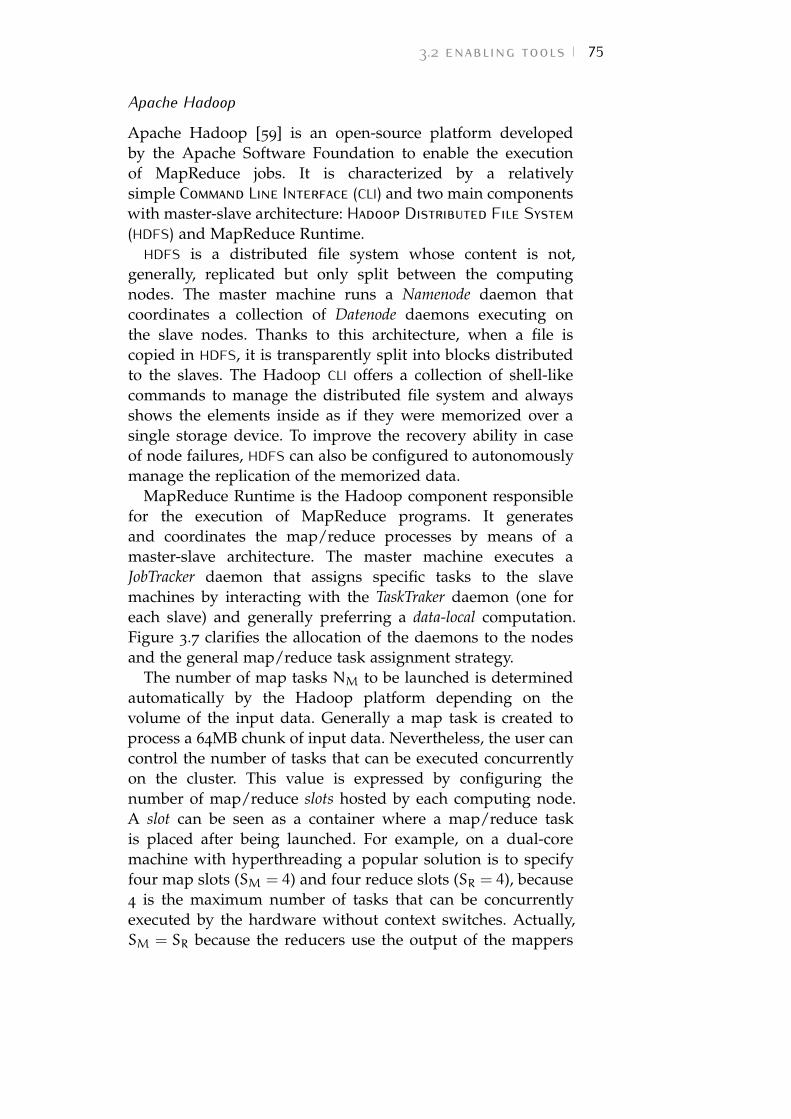
3.2 enabling tools 75
Apache Hadoop
Apache Hadoop [59] is an open-source platform developedby the Apache Software Foundation to enable the executionof MapReduce jobs. It is characterized by a relativelysimple Command Line Interface (CLI) and two main componentswith master-slave architecture: Hadoop Distributed File System(HDFS) and MapReduce Runtime.
HDFS is a distributed file system whose content is not,generally, replicated but only split between the computingnodes. The master machine runs a Namenode daemon thatcoordinates a collection of Datenode daemons executing onthe slave nodes. Thanks to this architecture, when a file iscopied in HDFS, it is transparently split into blocks distributedto the slaves. The Hadoop CLI offers a collection of shell-likecommands to manage the distributed file system and alwaysshows the elements inside as if they were memorized over asingle storage device. To improve the recovery ability in caseof node failures, HDFS can also be configured to autonomouslymanage the replication of the memorized data.
MapReduce Runtime is the Hadoop component responsiblefor the execution of MapReduce programs. It generatesand coordinates the map/reduce processes by means of amaster-slave architecture. The master machine executes aJobTracker daemon that assigns specific tasks to the slavemachines by interacting with the TaskTraker daemon (one foreach slave) and generally preferring a data-local computation.Figure 3.7 clarifies the allocation of the daemons to the nodesand the general map/reduce task assignment strategy.
The number of map tasks NM to be launched is determinedautomatically by the Hadoop platform depending on thevolume of the input data. Generally a map task is created toprocess a 64MB chunk of input data. Nevertheless, the user cancontrol the number of tasks that can be executed concurrentlyon the cluster. This value is expressed by configuring thenumber of map/reduce slots hosted by each computing node.A slot can be seen as a container where a map/reduce taskis placed after being launched. For example, on a dual-coremachine with hyperthreading a popular solution is to specifyfour map slots (SM = 4) and four reduce slots (SR = 4), because4 is the maximum number of tasks that can be concurrentlyexecuted by the hardware without context switches. Actually,SM = SR because the reducers use the output of the mappers
76 autonomic management in multiple clouds
Figure 3.7: When the execution command is issued to the Hadoopcluster through the CLI, the JobTracker on the master nodeis involved. It interacts with the Namenode daemon tocreate a number of map/reduce tasks consistent with thenumber of data blocks to be processed. The JobTrackeralso allocates the tasks preferring a data-local computa-tion. For example, the map working on block 001 is likelyto sent to machine 2 containing that block on its portionof HDFS.
and, therefore, the executions of these two phases do notoverlap.
The number of reduce task NR to be launched is controlledby the user with a specific option of the CLI. Hadoopdevelopers suggests two possible values (obtained throughstatistical analysis [59]) for NR depending on the hardwarecharacteristics. In particular, if the computing nodes havesimilar performance, the number of reduce tasks to belaunched should be set to NR = 0.95× SR. In case of coreswith different performance, Hadoop developers suggestsNR = 1.75× SR.
The rational behind these two values is intuitively in theattempt to obtain the maximum degree of parallelism in theexecution. In case of similar cores performance, the value isclose to 1 because this will assure to allocate a reduce taskto each reduce slot thus to complete the reduce phase in oneround. When the core performance are different, the executiontime for a given task can vary depending on the slot/core towhich the task is assigned. The multiply factor 1.75 makes
3.3 framework architecture 77
NR higher than SR, so that while the slower cores continue toexecute the reduce tasks of the first round, the faster ones havealready completed their task and can start a second round ofreducers.
MapReduce fault tolerance and elasticity
Thanks to its distributed architecture MapReduce program-ming model is particularly useful when a certain level of faulttolerance is required. Indeed, independently from the specificimplemented algorithm, two different error situations can beidentified and (partially) solved:
• if the master node identifies a fault on a slave – e.g.,the salve is no longer responding – but the data areaccessible (or replicated elsewhere in the distributed filesystem), the master can restart the map/reduce task ofthe faulty slave on another machine;• if the master identifies errors on some data blocks, can
decide to skip them and continue.
These fault tolerance mechanisms are implemented on all mainMapReduce platforms and contribute to improve the QoS ofthe data-parallel approach.
Alongside these mechanisms, Hadoop also implementsstrategies to improve the scalability of the computing clusterat runtime. If a new slave is added to the infrastructure whilesome MapReduce job is executing, Hadoop is able to assignpending tasks to it, thus to relieve the other machines andspeed up the computation.
This elastic behavior is particularly useful when Hadoop isexecuted on a scalable infrastructure i.e., an infrastructure thatallows the user to easily add or remove computing resourcesto the cluster, such as the cloud. In this environment VMs canbe provisioned (or de-provisioned) on demand, to support theneed for additional (or less) computing resource in a Hadoopcluster.
3.3 framework architectureOur contribution to enable MapReduce over hybrid cloud isa framework architecture [48] based on two separated cloudinstallations:
78 autonomic management in multiple clouds
• the on-premise IC, owned and managed by a privatecompany;• and the off-premise EC, a collection of resources owned
by a cloud provider and rented to customers accordingto a predefined price plan.
Having their own cloud management software and offeringtheir virtualized resources to final users (e.g., customers,company employees, etc...), both IC and EC implement thecloud paradigm at IaaS level.
As a case study, we consider the execution of data-intensiveapplications over clusters of VMs initially deployed on IC.Since the private cloud can be used by multiple users fordifferent goals at the same time, it is likely to happen thata physical machine simultaneously hosts VMs designed fordifferent application domains.
In this scenario, if a physical node hosting a VM fordata-processing becomes overloaded in terms of CPU, memoryor disk utilization (e.g., as a result of other computationscarried on the same physical machine by VMs belonging toother application domains/projects), the performance of thehostedVM may dramatically decrease, thus slowing down thewhole virtual cluster for data-processing.
In this case, if another less loaded physical machine isavailable on-premise, the best solution would be to move theVM on that physical node. The progresses in the techniques forVM migration has brought the possibility to move a VM from aphysical machine to another without need to suspend it andsuffering a minimal downtime. The fault tolerance featuresoffered by all MapReduce platforms can help to overcome thisdowntime an make the data analysis continue.
However, the private cloud has a finite amount of resourcesand it may happen that all the physical machines in IC aretoo loaded to receive the VM: in this case, we can provideadditional resources on EC and perform a redistribution ofthe computational load. Automating this mechanism – byarranging an autonomous infrastructure able to detect theoccurrence of a critical condition on a physical machine andreact to that by providing additional off-premise resourcesto the application level cluster involved – can represent akey advantage for data-processing computation on hybridenvironments.
To this purpose we defined a platform for the autonomicmanagement of VMs in hybrid clouds: System for HYbrid
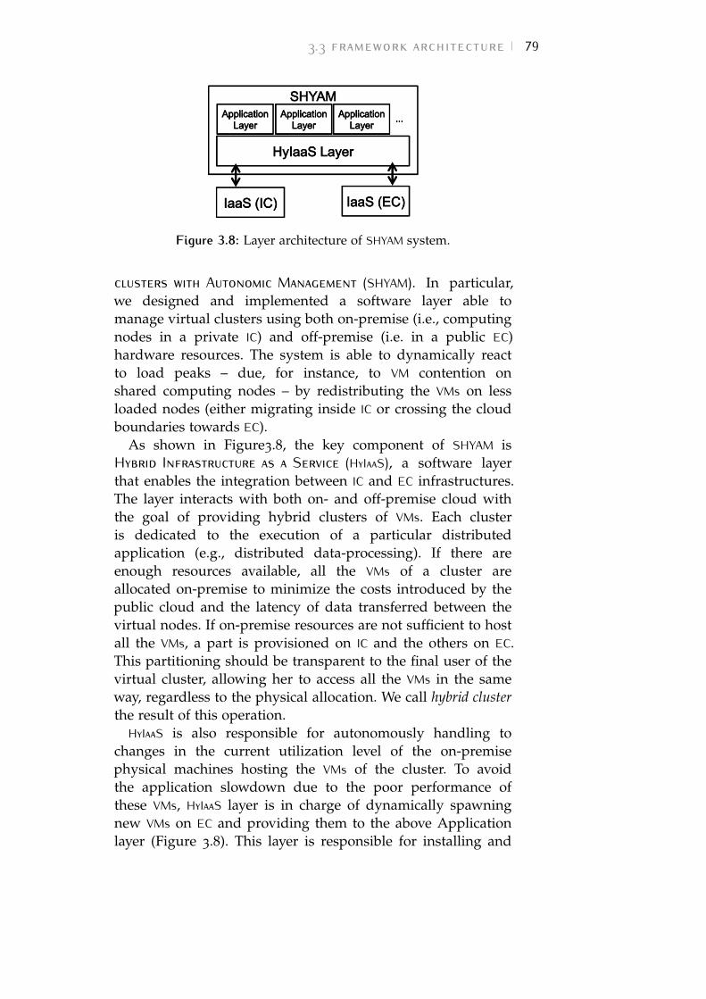
3.3 framework architecture 79
Figure 3.8: Layer architecture of SHYAM system.
clusters with Autonomic Management (SHYAM). In particular,we designed and implemented a software layer able tomanage virtual clusters using both on-premise (i.e., computingnodes in a private IC) and off-premise (i.e. in a public EC)hardware resources. The system is able to dynamically reactto load peaks – due, for instance, to VM contention onshared computing nodes – by redistributing the VMs on lessloaded nodes (either migrating inside IC or crossing the cloudboundaries towards EC).
As shown in Figure3.8, the key component of SHYAM isHybrid Infrastructure as a Service (HyIaaS), a software layerthat enables the integration between IC and EC infrastructures.The layer interacts with both on- and off-premise cloud withthe goal of providing hybrid clusters of VMs. Each clusteris dedicated to the execution of a particular distributedapplication (e.g., distributed data-processing). If there areenough resources available, all the VMs of a cluster areallocated on-premise to minimize the costs introduced by thepublic cloud and the latency of data transferred between thevirtual nodes. If on-premise resources are not sufficient to hostall the VMs, a part is provisioned on IC and the others on EC.This partitioning should be transparent to the final user of thevirtual cluster, allowing her to access all the VMs in the sameway, regardless to the physical allocation. We call hybrid clusterthe result of this operation.
HyIaaS is also responsible for autonomously handling tochanges in the current utilization level of the on-premisephysical machines hosting the VMs of the cluster. To avoidthe application slowdown due to the poor performance ofthese VMs, HyIaaS layer is in charge of dynamically spawningnew VMs on EC and providing them to the above Applicationlayer (Figure 3.8). This layer is responsible for installing and
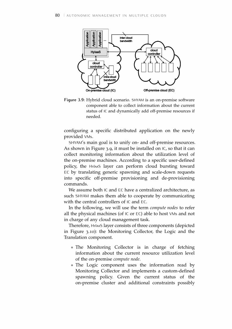
80 autonomic management in multiple clouds
Figure 3.9: Hybrid cloud scenario. SHYAM is an on-premise softwarecomponent able to collect information about the currentstatus of IC and dynamically add off-premise resources ifneeded.
configuring a specific distributed application on the newlyprovided VMs.
SHYAM’s main goal is to unify on- and off-premise resources.As shown in Figure 3.9, it must be installed on IC, so that it cancollect monitoring information about the utilization level ofthe on-premise machines. According to a specific user-definedpolicy, the HyIaaS layer can perform cloud bursting towardEC by translating generic spawning and scale-down requestsinto specific off-premise provisioning and de-provisioningcommands.
We assume both IC and EC have a centralized architecture, assuch SHYAM makes them able to cooperate by communicatingwith the central controllers of IC and EC.
In the following, we will use the term compute nodes to referall the physical machines (of IC or EC) able to host VMs and notin charge of any cloud management task.
Therefore, HyIaaS layer consists of three components (depictedin Figure 3.10): the Monitoring Collector, the Logic and theTranslation component.
• The Monitoring Collector is in charge of fetchinginformation about the current resource utilization levelof the on-premise compute node.• The Logic component uses the information read by
Monitoring Collector and implements a custom-definedspawning policy. Given the current status of theon-premise cluster and additional constraints possibly
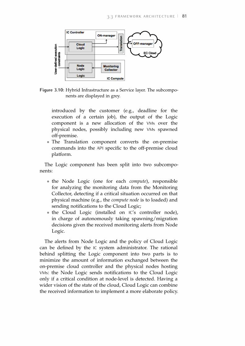
3.3 framework architecture 81
Figure 3.10: Hybrid Infrastructure as a Service layer. The subcompo-nents are displayed in grey.
introduced by the customer (e.g., deadline for theexecution of a certain job), the output of the Logiccomponent is a new allocation of the VMs over thephysical nodes, possibly including new VMs spawnedoff-premise.• The Translation component converts the on-premise
commands into the API specific to the off-premise cloudplatform.
The Logic component has been split into two subcompo-nents:
• the Node Logic (one for each compute), responsiblefor analyzing the monitoring data from the MonitoringCollector, detecting if a critical situation occurred on thatphysical machine (e.g., the compute node is to loaded) andsending notifications to the Cloud Logic;• the Cloud Logic (installed on IC’s controller node),
in charge of autonomously taking spawning/migrationdecisions given the received monitoring alerts from NodeLogic.
The alerts from Node Logic and the policy of Cloud Logiccan be defined by the IC system administrator. The rationalbehind splitting the Logic component into two parts is tominimize the amount of information exchanged between theon-premise cloud controller and the physical nodes hostingVMs: the Node Logic sends notifications to the Cloud Logiconly if a critical condition at node-level is detected. Having awider vision of the state of the cloud, Cloud Logic can combinethe received information to implement a more elaborate policy.
82 autonomic management in multiple clouds
If the new VM allocation produced by the Logic involves EC,the Translation component is used to convert the directivesinto EC-specific APIs.
As a case study, we focus on the data-intensive scenario,where the applicative load can be distributed among severalcomputing nodes. In order to control the complexity ofparallelization, we adopt the MapReduce model [58] and itsopen-source implementation platform Apache Hadoop [59].
We execute the Hadoop workload over a virtual cluster thatcan be deployed on the hybrid cloud (partitioned betweenIC and EC) in case the on-premise resources are not enough.Therefore, the first application layer we implement for SHYAMis responsible for installing and configuring Hadoop on thenewly provided VMs and allows us to evaluate the performanceof operating MapReduce in a hybrid cloud setup.
3.3.1 General Cost Model
In the following, we investigate the cost model of a genericapplication running on the hybrid cluster. The model weobtain is used for the implementation of the Logic componentto guide the dynamic resource provisioning mechanism.
Although we expect the cost model to mainly dependon the specific application-level workload executed by thevirtual cluster, we can nevertheless point out some generalrelation that must be specialized depending on the particularapplication.
Considering all the execution tasks and input data initiallydistributed over X virtual nodes on IC and a predefineddeadline T for the computation to be completed, we want toinvestigate under which hypothesis we can take advantagefrom spawning and how many VMs we need to provide on ECin order to satisfy the deadline constraint. The number Y ofoff-premise VMs to be spawned can be expressed as follows:
Y = fA(D,X,L, T), (3.2)
where D is the amount of data to be processed, L is theinter-cloud bandwidth and fA is a function strictly related tothe running application A. The deadline T must be comparedto the predicted total time Ttot_H needed for the computationto take place on the hybrid cluster. As we start from a fullyon-premise cluster of VMs, Ttot_H can be expressed as follows:
Ttot_H = Tp + Tc + Te, (3.3)
3.3 framework architecture 83
where Tp is the time to have Y VMs provided on EC up andrunning, Tc is the time to configure these newly provided VMsand Te is the effective time to execute the job on the resultinghybrid cluster.
Depending on the EC IaaS layer only, the provisioning timeTp can be estimated regardless to the specific applicationrunning on the hybrid cluster. When a spawning commandis issued to EC, the scheduler of the off-premise cloudinfrastructure must determine which physical machine canhost each newly provided VM. Intuitively, we expect theprovisioning time to be as follows:
Tp = o(Y) + ts_ov, (3.4)
where o(Y) is a component of Tp directly proportional to thenumber Y of spawned VMs and is strictly connected to theEC infrastructure performances. On the other hand, ts_ov isa constant overhead introduced by the EC scheduler. Tp canbe seen as an application-independent lower bound for Ttot_Hbecause no computation can start on the off-premise VMsbefore the provisioning operation is completed.
Unlike Tp, the configuration and execution times (Tc and Te)depend on the application-level tasks operated by the hybridcluster. In the following section we describe Tc and Te withreference to the particular execution scenario of MapReducedata-intensive applications.
3.3.2 Hybrid MapReduce Cost Model
Focusing on Hadoop implementation of MapReduce, theJob-Tracker on the master node assigns jobs to the workersaccording to the part of data currently allocated on theworker’s portion of HDFS.
Having no data initially allocated on the newly providedoff-premise workers, they will be scarcely useful for thecomputation, because the Job-Tracker will not assign anytask to them. Therefore, in case of Hadoop application, theconfiguration time Tc in Equation 3.3 must include the time toperform the distribution of the data (and the consequent taskallocation) across all the virtual nodes.
Hadoop platform offers a data balancing feature calledHadoop Balancer [59] that can be requested on-demand witha specific command or continuously executed by a daemonprocess. Whenever needed, the Balancer analyze and compare
84 autonomic management in multiple clouds
the utilization of the portion of HDFS on each worker. Ifthe utilization differs from the average such that it exceedsa tolerance interval (default set to [-10,10]%), the balancingprocess starts to move data blocks from the workers withhigher HDFS utilization to the underutilized ones.
We call "balancing time" Tb the amount of time needed forthis operation and we express Tc as follows:
Tc = Tb + tc_ov (3.5)
where tc_ov is the constant overhead introduced by genericconfigurations (e.g., changes in the configuration files, daemonstart-up, etc.)
In a hybrid scenario, Tb is strictly influenced by thebandwidth L between IC and EC and can be expressed as:
Tb =δ(X, Y,D)
L+ τ(X, Y,D,L) (3.6)
where δ is a function expressing the amount of data crossingthe on-/off-premise boundaries and τ addresses the timerequested by Hadoop Balancer to detect which blocks of datamust be moved and perform additional data transfer.
While it is rather simple to estimate the minimum amountof data we need to transfer from on- to off-premise cloud(to have input data balanced across all the VMs), it is harderto determine how much time is needed by Hadoop Balanceras it performs additional data movement. Hence, τ must beestimated through testing. However, this estimation has theadvantage of being independent from the specific MapReduceworkload going to be issued to Hadoop framework.
As regards the Te parameter in Equation 3.3, we can notethat the execution phase of MapReduce application over aHadoop hybrid cluster has no conceptual differences from theexecution on a set of on-premise VMs (assuming the samenumber of virtual servers with the same computing power inboth the scenarios). Nevertheless, it is crucial to consider thatin the hybrid case, Y off-premise VMs are reachable through alower bandwidth medium.
We expect the execution time Te_H(Z) in a hybrid scenariowith Z VMs to be higher than the execution time Te_I(Z) on afully on-premise cluster of Z co-located VMs, resulting in thefollowing:
Te_H(Z) > Te_I(Z) (3.7)
3.3 framework architecture 85
In the case of a Hadoop application, the mapper tasks mainlywork on local data, while the reducers collect input data frommappers’ output. For this reason the delay of hybrid executionis mainly due to Hadoop’s shuffle phase (i.e., when theintermediate output from the mappers is sent to the reducers).Since the amount of data shuffled depends on the workloadand the particular data set involved, the execution time Te inEquation 3.3 can only be experimentally estimated.
3.3.3 Implementation details
We implemented HyIaaS by extending OpenStack Sahara [109]component to allow cluster scaling operations in a hybridscenario.
As described in Chapter 3.2.1, OpenStack [5] is anopen source platform for cloud computing with a modulararchitecture and Sahara is the OpenStack module specific todata processing.
OpenStack Sahara allow the user to quickly deploy,configure and scale virtual clusters dedicated to data intensiveapplications like MapReduce. We modified Sahara scalingmechanism to allow the spawning of new VMs on a remotecloud.
The Monitoring Collector component is a simple daemonprocess running on each compute node and collecting thepercentage of physical resource utilization. It checks the CPU,RAM and disk usage on the compute nodes and sends thisinformation to the Logic component where it is used to detectthe need for new resources. The monitoring data can be furthercoupled with those collected by the OpenStack Ceilometermodule [110] (i.e., utilization of virtual resources on each VM).
When the virtual cluster needs to be scaled by providingnew off-premise VMs, the command is issued through theTranslation component to EC. In our test scenario, the off-premise cloud runs another OpenStack installation, thereforethe Translation component simply forward the provisioningcommand to EC’s OpenStack component in charge of VMmanagement – i.e., OpenStack Nova Compute module.
The MapReduce Application layer finally configures Hadoopand launches its daemons by connecting to the newly providedVMs.
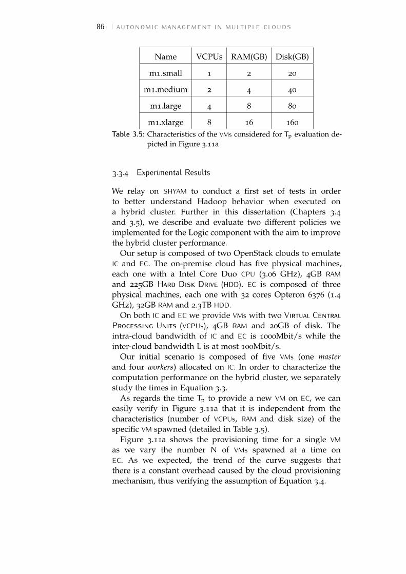
86 autonomic management in multiple clouds
Name VCPUs RAM(GB) Disk(GB)
m1.small 1 2 20
m1.medium 2 4 40
m1.large 4 8 80
m1.xlarge 8 16 160
Table 3.5: Characteristics of the VMs considered for Tp evaluation de-picted in Figure 3.11a
3.3.4 Experimental Results
We relay on SHYAM to conduct a first set of tests in orderto better understand Hadoop behavior when executed ona hybrid cluster. Further in this dissertation (Chapters 3.4and 3.5), we describe and evaluate two different policies weimplemented for the Logic component with the aim to improvethe hybrid cluster performance.
Our setup is composed of two OpenStack clouds to emulateIC and EC. The on-premise cloud has five physical machines,each one with a Intel Core Duo CPU (3.06 GHz), 4GB RAMand 225GB Hard Disk Drive (HDD). EC is composed of threephysical machines, each one with 32 cores Opteron 6376 (1.4GHz), 32GB RAM and 2.3TB HDD.
On both IC and EC we provide VMs with two Virtual CentralProcessing Units (VCPUs), 4GB RAM and 20GB of disk. Theintra-cloud bandwidth of IC and EC is 1000Mbit/s while theinter-cloud bandwidth L is at most 100Mbit/s.
Our initial scenario is composed of five VMs (one masterand four workers) allocated on IC. In order to characterize thecomputation performance on the hybrid cluster, we separatelystudy the times in Equation 3.3.
As regards the time Tp to provide a new VM on EC, we caneasily verify in Figure 3.11a that it is independent from thecharacteristics (number of VCPUs, RAM and disk size) of thespecific VM spawned (detailed in Table 3.5).
Figure 3.11a shows the provisioning time for a single VMas we vary the number N of VMs spawned at a time onEC. As we expected, the trend of the curve suggests thatthere is a constant overhead caused by the cloud provisioningmechanism, thus verifying the assumption of Equation 3.4.
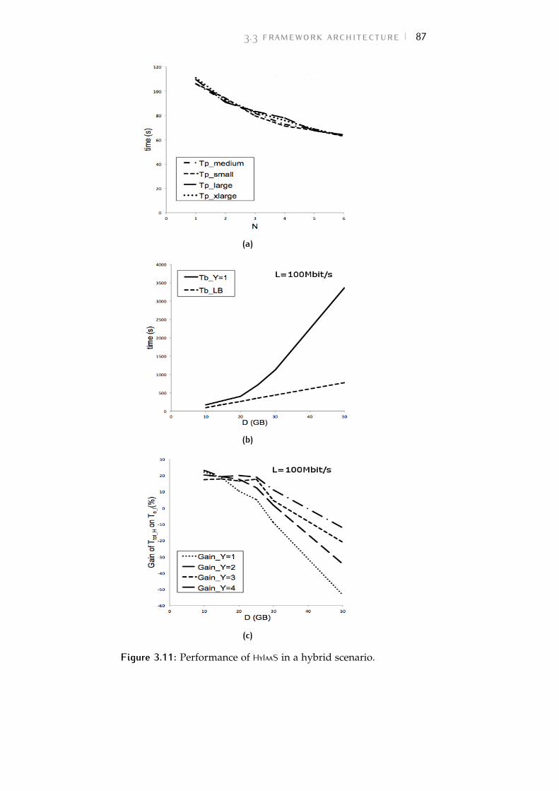
3.3 framework architecture 87
(a)
(b)
(c)
Figure 3.11: Performance of HyIaaS in a hybrid scenario.
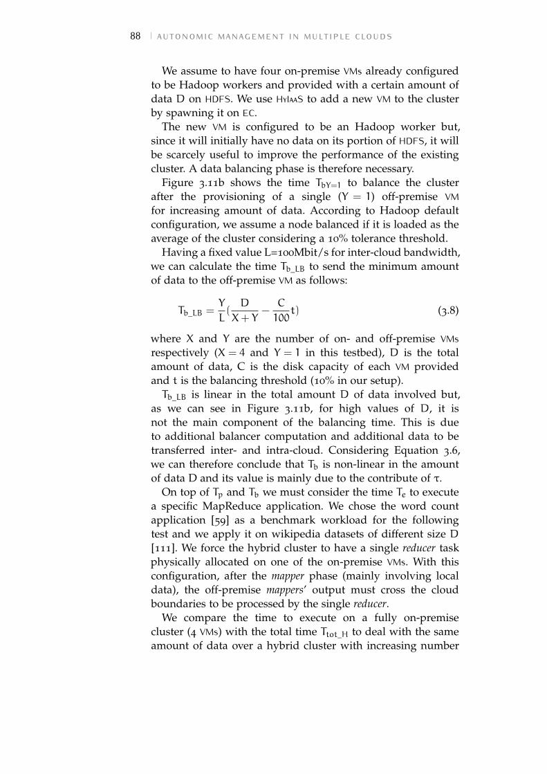
88 autonomic management in multiple clouds
We assume to have four on-premise VMs already configuredto be Hadoop workers and provided with a certain amount ofdata D on HDFS. We use HyIaaS to add a new VM to the clusterby spawning it on EC.
The new VM is configured to be an Hadoop worker but,since it will initially have no data on its portion of HDFS, it willbe scarcely useful to improve the performance of the existingcluster. A data balancing phase is therefore necessary.
Figure 3.11b shows the time TbY=1 to balance the clusterafter the provisioning of a single (Y = 1) off-premise VMfor increasing amount of data. According to Hadoop defaultconfiguration, we assume a node balanced if it is loaded as theaverage of the cluster considering a 10% tolerance threshold.
Having a fixed value L=100Mbit/s for inter-cloud bandwidth,we can calculate the time Tb_LB to send the minimum amountof data to the off-premise VM as follows:
Tb_LB =Y
L(D
X+ Y−C
100t) (3.8)
where X and Y are the number of on- and off-premise VMsrespectively (X = 4 and Y = 1 in this testbed), D is the totalamount of data, C is the disk capacity of each VM providedand t is the balancing threshold (10% in our setup).Tb_LB is linear in the total amount D of data involved but,
as we can see in Figure 3.11b, for high values of D, it isnot the main component of the balancing time. This is dueto additional balancer computation and additional data to betransferred inter- and intra-cloud. Considering Equation 3.6,we can therefore conclude that Tb is non-linear in the amountof data D and its value is mainly due to the contribute of τ.
On top of Tp and Tb we must consider the time Te to executea specific MapReduce application. We chose the word countapplication [59] as a benchmark workload for the followingtest and we apply it on wikipedia datasets of different size D[111]. We force the hybrid cluster to have a single reducer taskphysically allocated on one of the on-premise VMs. With thisconfiguration, after the mapper phase (mainly involving localdata), the off-premise mappers’ output must cross the cloudboundaries to be processed by the single reducer.
We compare the time to execute on a fully on-premisecluster (4 VMs) with the total time Ttot_H to deal with the sameamount of data over a hybrid cluster with increasing number
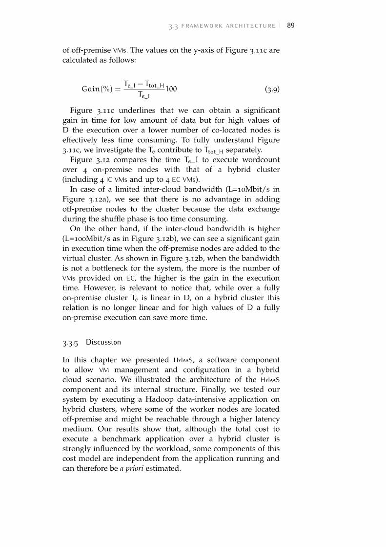
3.3 framework architecture 89
of off-premise VMs. The values on the y-axis of Figure 3.11c arecalculated as follows:
Gain(%) =Te_I − Ttot_H
Te_I100 (3.9)
Figure 3.11c underlines that we can obtain a significantgain in time for low amount of data but for high values ofD the execution over a lower number of co-located nodes iseffectively less time consuming. To fully understand Figure3.11c, we investigate the Te contribute to Ttot_H separately.
Figure 3.12 compares the time Te_I to execute wordcountover 4 on-premise nodes with that of a hybrid cluster(including 4 IC VMs and up to 4 EC VMs).
In case of a limited inter-cloud bandwidth (L=10Mbit/s inFigure 3.12a), we see that there is no advantage in addingoff-premise nodes to the cluster because the data exchangeduring the shuffle phase is too time consuming.
On the other hand, if the inter-cloud bandwidth is higher(L=100Mbit/s as in Figure 3.12b), we can see a significant gainin execution time when the off-premise nodes are added to thevirtual cluster. As shown in Figure 3.12b, when the bandwidthis not a bottleneck for the system, the more is the number ofVMs provided on EC, the higher is the gain in the executiontime. However, is relevant to notice that, while over a fullyon-premise cluster Te is linear in D, on a hybrid cluster thisrelation is no longer linear and for high values of D a fullyon-premise execution can save more time.
3.3.5 Discussion
In this chapter we presented HyIaaS, a software componentto allow VM management and configuration in a hybridcloud scenario. We illustrated the architecture of the HyIaaScomponent and its internal structure. Finally, we tested oursystem by executing a Hadoop data-intensive application onhybrid clusters, where some of the worker nodes are locatedoff-premise and might be reachable through a higher latencymedium. Our results show that, although the total cost toexecute a benchmark application over a hybrid cluster isstrongly influenced by the workload, some components of thiscost model are independent from the application running andcan therefore be a priori estimated.
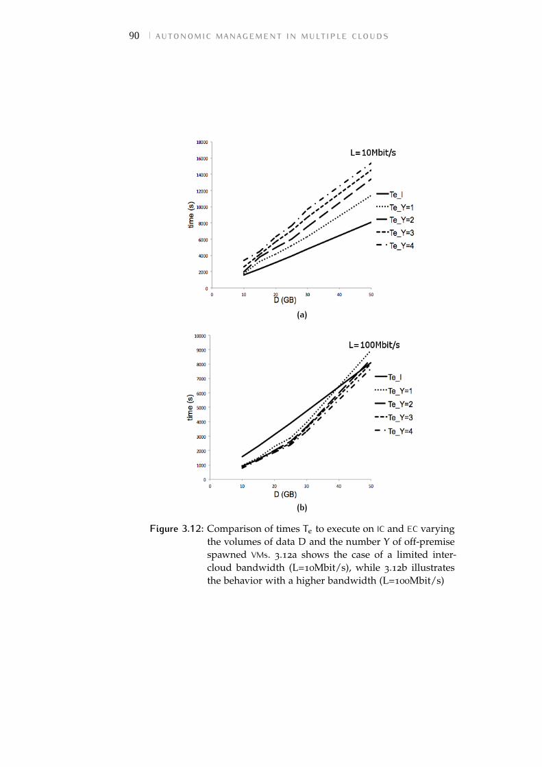
90 autonomic management in multiple clouds
(a)
(b)
Figure 3.12: Comparison of times Te to execute on IC and EC varyingthe volumes of data D and the number Y of off-premisespawned VMs. 3.12a shows the case of a limited inter-cloud bandwidth (L=10Mbit/s), while 3.12b illustratesthe behavior with a higher bandwidth (L=100Mbit/s)
3.4 the span policy 91
This work represents a first step towards the implementationof an autonomic "Hybrid Infrastructure as a Service" system,able to forecast the computing resources needed by eachon-premise application and to autonomously request them toEC. We used HyIaaS for the quick deploy of hybrid clusters ofVMs aiming to execute a MapReduce workload by means of theHadoop framework.
The execution time model needs to be refined by analyzingother MapReduce workloads and studying the connectionswith the volumes of data exchanged during the Hadoopshuffle phase. Since the processing time of a MapReduceapplication in a hybrid cluster is also influenced by the numberand the allocation (on- or off-premise) of the reducers, furtherinvestigations of the performance are needed when more thenone reduce task is running.
Nevertheless, the results of this work are useful to clarifythe trends of execution times for MapReduce applications overan interconnected multiple cloud scenario. The study showsthat the main obstacle to the final goal of enabling MapReduceover an hybrid cluster of VMs is the limitation introducedwhen the inter-cloud bandwidth is saturated. Indeed, thisfactor is responsible of the evolution in the execution timefrom a linear trend (proportional to the volumes of datainvolved) on a fully on-premise cluster to a non-linear trendon a hybrid environment. It is therefore necessary to containthe amount of data flowing through the on-/off-premiseboundaries, eventually avoiding to appeal to Hadoop Balancerprocess for the initial redistribution of the input data.
Focusing on the scenario described in Chapter 3.3, wecontinue this dissertation by providing two managementpolicies for HyIaaS Logic component aiming to both performcloud bursting when needed and contain the volumes of dataspawned off-premise.
3.4 the span policyWe consider the scenario of a private cloud used forMapReduce data-processing and for various other goals atthe same time. In this case, it is likely to happen thata physical machine simultaneously hosts VMs designed fordifferent application domains. If a compute node hosting aMapReduce worker VM becomes overloaded as a result of
92 autonomic management in multiple clouds
other computations carried on the same physical machineby VMs belonging to other projects, the performance of theMapReduce worker may dramatically decrease, thus slowingdown the whole virtual cluster for data-processing.
For this reason, we implemented a first example of policyfor the Logic component executed on every compute node ofIC: the SPAN policy (Algorithm 9). The work included in thischapter was published in [98].
SPAN aims to maintain the load of each compute nodeunder parametric threshold THRU. It periodically checks theresource utilization of the compute node h (line 2 in Algorithm9). If the load exceeds THRU, the procedure selects to movea subset of the VMs currently on h (line 3 in Algorithm 9).The selectToMove function is implemented according to MoMalgorithm from Beloglazov et al. [39]. This policy ensuresto always move the minimum number of VMs that brings hutilization back under THRU.
For each vm selected, if there is another on-premise nodethat can host the VM, a migration is performed (line 7 inAlgorithm 9). Otherwise, if no IC’s compute node can hostthe VM, a new one is spawned off-premise and the specificapplication level operation is performed (swap() in line 10 ofAlgorithm 9).
We chose Hadoop as an example of distributed data-processing platform. For this reason, swap procedure(Algorithm 10) simply consists of performing an Hadoopinstallation on vmnew and including it in the cluster whilethe old on-premise vm is excluded by performing Hadoopdecommissioning procedure [59]. This operation automaticallycopies to the other workers of the cluster the portion ofHDFS data on vm and marks it to be excluded from taskassignment. However, Hadoop does not really delete thedata on the decommissioned worker: they remain on theold vm unless it is actually remove. Hence, we performONmanager.remove(vm) in the SPAN algorithm once theswap procedure has competed (line 11 in Algorithm 9).
Focusing on the cl.include(vmnew) operation in line 3 ofAlgorithm 10, we must consider that Hadoop’s Job-Tracker(running on the master node) assigns jobs to the workersaccording to the part of data currently allocated on theworker’s portion of HDFS. Having no data initially allocated onthe newly included off-premise workers, they will be scarcely
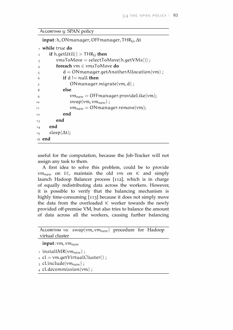
3.4 the span policy 93
Algorithm 9: SPAN policy
input :h,ONmanager,OFFmanager, THRU,∆t
1 while true do2 if h.getUtil() > THRU then3 vmsToMove = selectToMove(h.getVMs()) ;4 foreach vm ∈ vmsToMove do5 d = ONmanager.getAnotherAllocation(vm) ;6 if d != null then7 ONmanager.migrate(vm,d) ;8 else9 vmnew = OFFmanager.provideLike(vm);
10 swap(vm, vmnew) ;11 vmnew = ONmanager.remove(vm);12 end13 end14 end15 sleep(∆t);16 end
useful for the computation, because the Job-Tracker will notassign any task to them.
A first idea to solve this problem, could be to providevmnew on EC, maintain the old vm on IC and simplylaunch Hadoop Balancer process [112], which is in chargeof equally redistributing data across the workers. However,it is possible to verify that the balancing mechanism ishighly time-consuming [113] because it does not simply movethe data from the overloaded IC worker towards the newlyprovided off-premise VM, but also tries to balance the amountof data across all the workers, causing further balancing
Algorithm 10: swap(vm, vmnew) procedure for Hadoopvirtual cluster
input : vm, vmnew
1 installMR(vmnew) ;2 cl = vm.getVirtualCluster() ;3 cl.include(vmnew) ;4 cl.decommission(vm) ;
94 autonomic management in multiple clouds
computation and additional data to be transferred inter- andintra-cloud.
Another solution cloud be to perform an inter-cloudmigration by transferring off-premise a snapshot of theoverloaded VM. This operation would ensure to move theminimum portion of HDFS to EC, but will also cause other partsof the VM (operating system, configurations, applications,etc.) to be transferred. Furthermore, given the intrinsicheterogeneity of the hybrid cloud environment, the inter-cloudlive mobility is currently a challenging field [85], and can havepoor performance due to the large size or the VM snapshotinvolved and the limited inter-cloud bandwidth.
For this reason, our solution is to relay on a wellknown Hadoop behavior: when the on-premise vm isdecommissioned and its data are replicated, Hadoop prefersthe workers with low utilization of HDFS as destinations.Initially having 0% HDFS utilization, off-premise vmnew islikely to be preferred and no other data balancing is neededto give vmnew an effective role in computation. Therefore,cl.decommission(vm) in line 4 of Algorithm 10 is enough totrigger the data replication process and avoid the drawbacks ofHadoop data balancing process. It also produces the benefitsof an inter-cloud VM migration (i.e., the minimum portionof HDFS is moved to EC) without performing the whole VMsnapshot transfer.
3.4.1 Experimental results
In order to test the performance of SPAN policy, we relay onthe same infrastructure used for the validation of the costmodel (Chapter 3.3.4).
In this scenario, we assume to have four on-premise workerVMs already configured to run Hadoop jobs and provided witha certain amount of data D on HDFS.
We consider the time to execute a word count Hadoopjob [108] over Wikipedia datasets of different size D [111].Figure 3.13a compares the execution time trends of threescenarios. The first one (Te_I in Figure 3.13a) representsthe ideal situation of having each Hadoop VM allocated onan on-premise dedicated physical machine. Since no otherphysical or virtual load is affecting the execution, we canobtain good performance (execution time is linear in D).
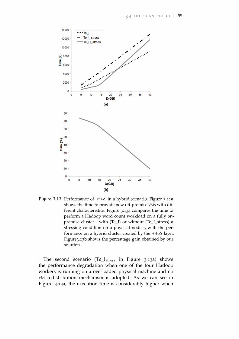
3.4 the span policy 95
(a)
(b)
Figure 3.13: Performance of HyIaaS in a hybrid scenario. Figure 3.11ashows the time to provide new off-premise VMs with dif-ferent characteristics. Figure 3.13a compares the time toperform a Hadoop word count workload on a fully on-premise cluster - with (Te_I) or without (Te_I_stress) astressing condition on a physical node -, with the per-formance on a hybrid cluster created by the HyIaaS layer.Figure3.13b shows the percentage gain obtained by oursolution.
The second scenario (Te_Istress in Figure 3.13a) showsthe performance degradation when one of the four Hadoopworkers is running on a overloaded physical machine and noVM redistribution mechanism is adopted. As we can see inFigure 3.13a, the execution time is considerably higher when
96 autonomic management in multiple clouds
compared to Te_I because the VM on the stressed physicalnode sensibly slows down the whole distributed computation.
The third scenario (Te_Hstress in Figure 3.13a) repeats thesecond scenario and uses SHYAM infrastructure with SPANpolicy. THRU is fixed at 90%. In this case, a new VM isspawned off-premise and the on-premise worker running onthe stressed machine is decommissioned (i.e., excluded fromHadoop cluster after its data have been copied on otherworker nodes). This operation causes a part of data to crosson-/off-premise boundaries.
As we can see in Figure 3.13a, the adoption of SPAN policycan considerably improve the performance for low values of D.However, (as already noticed in Chapter 3.3.4) the trends showthat in the hybrid scenario the execution time is no longerlinear in the volume of data involved and, for high values ofD, the time gain determined by the off-premise resources isconsiderably reduced. This is mainly due to data movementacross the on-/off-premise boundaries, which is usually over ahigher latency medium when compared to a fully on-premisecomputation.
Figure 3.13b shows the gain in execution time obtainedwith SHYAM. Although for high volumes of data crossingon-/off-premise boundaries the gain is low, the graph suggeststhat the autonomic provisioning and configuration of VMs onEC can represent a good solution to face critical conditions ofstress in private clouds.
3.4.2 Discussion
Relaying on SHYAM system, we developed a new policy for themanagement of data-processing clusters of VMs in a hybridcloud environment.
We evaluate SPAN policy performance by executing aHadoop application on a virtual cluster and stressing oneof the IC’s physical machines. In the given scenario, SHYAMautonomously spawns new VMs on EC and configures them asworkers of the Hadoop cluster.
Our results show that the hybrid cluster obtained cansensibly improve the performance of a benchmark Hadoopword count application. However, for high volumes of datacrossing on-/off-premise boundaries, the performance of thehybrid cluster decreases as the inter-cloud bandwidth issaturated. Since this drawback could be also influenced by the
3.5 the hymr policy 97
kind of application executed (e.g., word count in our casestudy), we need to further investigate SHYAM performance withdifferent Hadoop workloads.
Furthermore, in SPAN policy we trigger the spawning/mi-gration mechanism if the physical machine’s CPU utilizationexceeds THRU. In the following chapter, we modify the policyto take into account the utilization of other resources (RAM anddisk.).
In case of spawning new VMs towards EC, SPAN approachlacks a mechanism for “bringing back" on IC the off-premiseVMs once the critical condition is solved. Therefore, as a naturalevolution of SPAN, the policy in the next chapter implementsa symmetric threshold mechanism to detect underloaded hostsin IC.
Finally, as SPAN policy is actually performed only on thecompute nodes, it lacks a mechanism to coordinate the wholeinfrastructure. This can result in inconsistent evolutions ofthe algorithm, specially if we deal with further complicatedpolicies. Such kind of situations are avoided in the followingby introducing a policy central controller that coordinates thereactions of the compute nodes to critical condition.
3.5 the hymr policyGiven the limits of SPAN policy depicted in the previouschapter, we improved the HyIaaS Logic component policy toaddress the scale-down issue and take into account otherhardware resources in addition to CPU utilization.
The result is Hybrid MapReduce (HyMR) [99], a policy incharge of the autonomic scaling of Hadoop clusters over thehybrid cloud. Similarly to SPAN, this policy also performsapplication level tasks, such as installing and configuringHadoop on the newly provided VMs. HyMR is split into twoparts: the HyMR Node and HyMR Cloud policies, as suggestedby the Logic component implementation (Figure 3.10).
HyMR Node policy (Algorithm 11) is executed on everycompute node of IC and aims to maintain the resourceutilization between two parametric thresholds. It periodicallychecks the CPU, RAM and disk utilization of the compute nodeh (line 3 in Algorithm 11) and, if one of these values exceedsthe correspondent threshold, the procedure selects to movea subset of the VMs currently on h (line 5 in Algorithm 11).
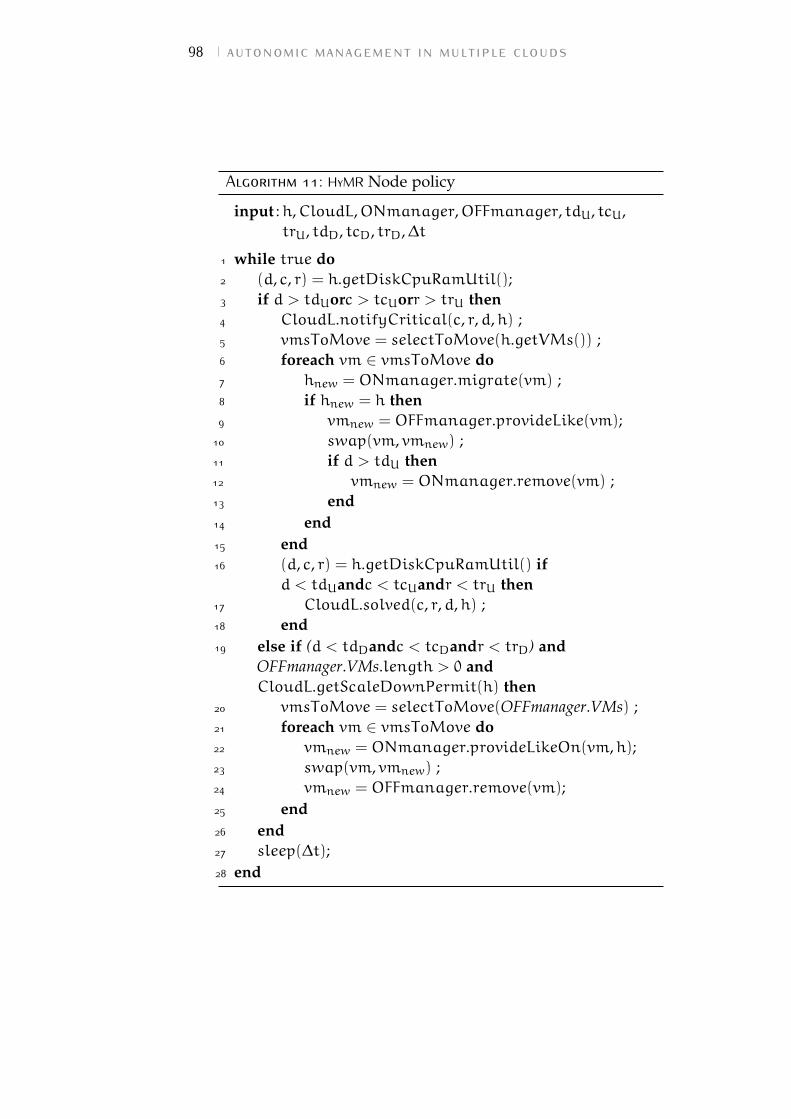
98 autonomic management in multiple clouds
Algorithm 11: HyMR Node policy
input :h,CloudL,ONmanager,OFFmanager, tdU, tcU,trU, tdD, tcD, trD,∆t
1 while true do2 (d, c, r) = h.getDiskCpuRamUtil();3 if d > tdUorc > tcUorr > trU then4 CloudL.notifyCritical(c, r,d,h) ;5 vmsToMove = selectToMove(h.getVMs()) ;6 foreach vm ∈ vmsToMove do7 hnew = ONmanager.migrate(vm) ;8 if hnew = h then9 vmnew = OFFmanager.provideLike(vm);
10 swap(vm, vmnew) ;11 if d > tdU then12 vmnew = ONmanager.remove(vm) ;13 end14 end15 end16 (d, c, r) = h.getDiskCpuRamUtil() if
d < tdUandc < tcUandr < trU then17 CloudL.solved(c, r,d,h) ;18 end19 else if (d < tdDandc < tcDandr < trD) and
OFFmanager.VMs.length > 0 andCloudL.getScaleDownPermit(h) then
20 vmsToMove = selectToMove(OFFmanager.VMs) ;21 foreach vm ∈ vmsToMove do22 vmnew = ONmanager.provideLikeOn(vm,h);23 swap(vm, vmnew) ;24 vmnew = OFFmanager.remove(vm);25 end26 end27 sleep(∆t);28 end
3.5 the hymr policy 99
The selectToMove function is implemented according to theMoM algorithm from Beloglazov et al. [39]. This policy ensuresto always move the minimum number of VMs that brings hutilization back under the exceeded threshold.
Furthermore, if we assume that the VMs are “small" –in terms of CPU, RAM and disk characteristics – whencompared to the physical machine hardware and their resourceutilization does not substantially obscillate, the Minimizationof Migration policy also guarantees to avoid glitches in thescale-up/-down mechanism, i.e., constantly moving VMs backand forth between IC and EC.
For each vm selected, if there is another on-premise nodethat can host the VM, a migration is performed (line 7 inAlgorithm 11). Otherwise, if no IC’s compute node can hostthe VM, a new VM is spawned off-premise and the swap
procedure is called in order to reconfigure the Hadoop cluster(Algorithm 10). As clarified in the previous chapter, the swapprocedure trigger the data replication process avoiding thedrawbacks of Hadoop data balancing process and producesthe benefits of an inter-cloud VM migration (i.e., the minimumportion of HDFS is moved to EC) without performing the wholeVM snapshot transfer. Note that, swap operation automaticallycopies the portion of HDFS currently on vm to the otherworkers of the cluster and marks vm to be excluded from taskassignment. However, Hadoop does not really delete the dataon the decommissioned worker: they remain on vm in case itwill be included back in the cluster in the future.
For this reason, after the swap procedure, if the criticalcondition that caused the spawning was a disk overloading,we need to instruct the on-premise cloud controller to actuallyremove the vm (line 12 in Algorithm 11). On the other hand,if the critical condition was related to RAM or CPU overloading,we prefer to maintain vm and its data on IC (although ithas been decommissioned) to speed up future scale-downoperations.
When the Monitoring Collector component detects thateither the CPU, RAM or disk utilization of the compute nodeis under the corresponding threshold and some VMs of thecurrent virtual cluster are allocated on EC, an analogous set ofoperations is performed (lines 19-25) to bring back all (or partof) the off-premise VMs, thus to minimize the cost of publiccloud resource utilization.
100 autonomic management in multiple clouds
In this scale-down scenario, if a copy of the data on theoff-premise VMs going to be decommissioned is also availableon-premise, the operation can be performed fastly. We referit as Fast Scale Down (FSD). On the contrary, if the portionof HDFS off-premise is not replicated on IC – e.g., if we wereobliged to perform a remove(vm) to satisfy the disk utilizationconstraint as in line 12 of Algorithm 11 –, the scale downwill cause all the data on the off-premise VM to be copiedon-premise before the decommissioning process can end. Werefer this case as Complete Scale Down (CSD) in the following.
Since HyMR Node policy is executed in a decentralizedway on each compute node, we need a mechanism tocoordinate scale-up and -down decisions in order to avoid theunderloaded physical hosts of IC to receive off-premise VMswhen some other IC’s host is overloaded (and would thereforebenefit from an intra-cloud migration). This mechanism isrealized by the HyMR Cloud policy (running on the cloudcontroller), which receives the notification of critical conditionoccurred and solved from each physical hosts of the cloudthrough notifyCritical() and solved() operations in line 4
and 17 of Algorithm 11. The Cloud policy temporary storesthis information and uses it to grant or deny the scale-downpermission to underloaded hosts (getScaleDownPermit(h) inline 19)
3.5.1 Experimental results
The performance of the cluster are evaluated on theinfrastructure described in Chapter 3.3.4 by executing threedifferent Hadoop workloads: word count, inverted index (overWikipedia datasets of different size D [111]) and tera sort(over a collection of rows randomly generated with teragenapplication [59]).
In order to obtain the best performance for the reduce phasein a hybrid setup, we chose to launch 8 reduce tasks (one foreach core in the cluster) in all the experiments, making surethat they are executed both on- and off-premise, as suggestedby the results of the work in [88].
When the Monitoring Collector installed on a physicalmachine detects a critical condition according to HyMR policy,one or more VMs are spawned off-premise. As proven inChapter 3.3.4 (and detailed in [46]) the provisioning timeis linear in the number of provisioned VMs (a part from a
3.5 the hymr policy 101
constant overhead introduced by HyIaaS) and independent fromtheir characteristics. Therefore, in the following, we overlookprovisioning and investigate the execution and decomissioningtime only.
Graphs in Figure 3.14a, 3.14b and 3.14c respectively showthe performance of word count, inverted index and terasort. Inparticular, each graph compares the execution time trends ofthree scenarios: Te_I, Te_Istress and Te_Hstress.
The first one (Te_I) represents the ideal situation of havingeach Hadoop VM allocated on an on-premise dedicatedphysical machine. Since no other physical or virtual load isaffecting the execution, we can obtain an execution time linearin D for all the workloads.
The second scenario (Te_Istress) shows the performancedegradation when one of the four Hadoop workers is runningon a overloaded physical machine and no VM redistributionmechanism is adopted. As we can see in Figure 3.14a, 3.14band 3.14c, the execution time is considerably higher whencompared to Te_I (particularly for word count and invertedindex) because the VM on the stressed physical node sensiblyslows down the whole distributed computation.
The third scenario (Te_Hstress) repeats the second scenarioand adopts HyIaaS infrastructure with HyMR policy. tcU, trU andtdU are set at 90%, while tcD, trD and tdD are 10%. In thiscase, a new VM is spawned off-premise and the on-premiseworker running on the stressed machine is decommissioned(i.e., excluded from Hadoop cluster after its data have beencopied on other worker nodes). This operation causes a part ofdata to cross the on-/off-premise boundaries.
All the stress tests in 3.14 are conducted by artificiallystressing the RAM of the physical machine but analogousresults can be obtained by stressing the RAM or disk.
Figure 3.15 shows the gain in execution time obtained byour solution (Te_Hstress compared to Te_Istress) in case ofone physical machine stressed. This graph is useful to betterclarify the trends of Figure 3.14a, 3.14b and 3.14c. For allthe workloads, the gain decreases as we augment the volumeof input data D. This is mainly due to data movementacross the on-/off-premise boundaries, which is usually over ahigher latency medium when compared to a fully on-premisecomputation.
In particular, both word count and inverted index showa stronger gain when compared to terasort. This is due to
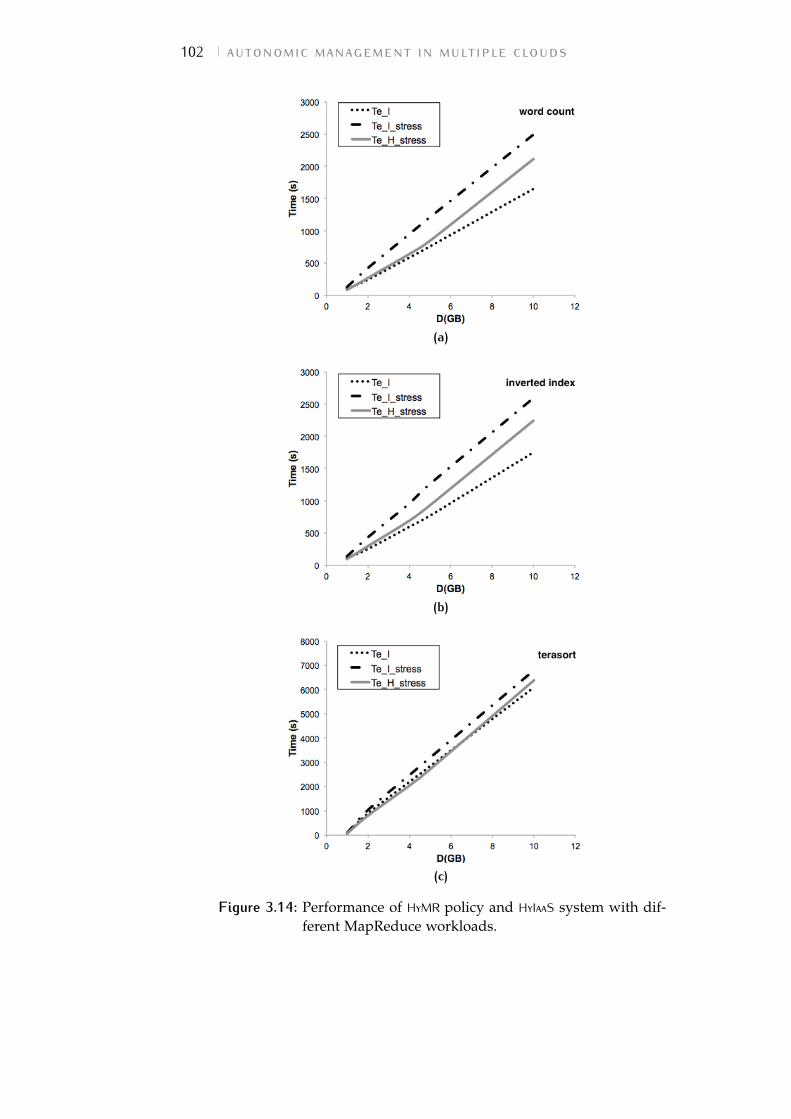
102 autonomic management in multiple clouds
(a)
(b)
(c)
Figure 3.14: Performance of HyMR policy and HyIaaS system with dif-ferent MapReduce workloads.
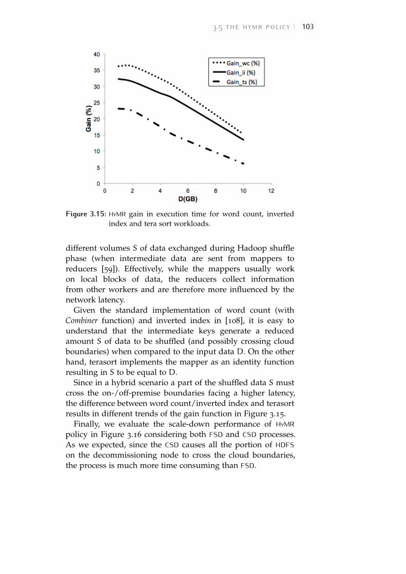
3.5 the hymr policy 103
Figure 3.15: HyMR gain in execution time for word count, invertedindex and tera sort workloads.
different volumes S of data exchanged during Hadoop shufflephase (when intermediate data are sent from mappers toreducers [59]). Effectively, while the mappers usually workon local blocks of data, the reducers collect informationfrom other workers and are therefore more influenced by thenetwork latency.
Given the standard implementation of word count (withCombiner function) and inverted index in [108], it is easy tounderstand that the intermediate keys generate a reducedamount S of data to be shuffled (and possibly crossing cloudboundaries) when compared to the input data D. On the otherhand, terasort implements the mapper as an identity functionresulting in S to be equal to D.
Since in a hybrid scenario a part of the shuffled data S mustcross the on-/off-premise boundaries facing a higher latency,the difference between word count/inverted index and terasortresults in different trends of the gain function in Figure 3.15.
Finally, we evaluate the scale-down performance of HyMRpolicy in Figure 3.16 considering both FSD and CSD processes.As we expected, since the CSD causes all the portion of HDFSon the decommissioning node to cross the cloud boundaries,the process is much more time consuming than FSD.
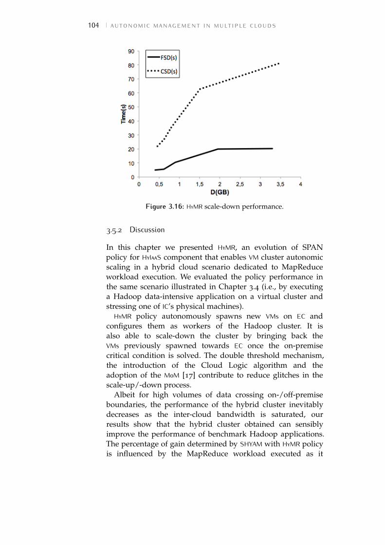
104 autonomic management in multiple clouds
Figure 3.16: HyMR scale-down performance.
3.5.2 Discussion
In this chapter we presented HyMR, an evolution of SPANpolicy for HyIaaS component that enables VM cluster autonomicscaling in a hybrid cloud scenario dedicated to MapReduceworkload execution. We evaluated the policy performance inthe same scenario illustrated in Chapter 3.4 (i.e., by executinga Hadoop data-intensive application on a virtual cluster andstressing one of IC’s physical machines).
HyMR policy autonomously spawns new VMs on EC andconfigures them as workers of the Hadoop cluster. It isalso able to scale-down the cluster by bringing back theVMs previously spawned towards EC once the on-premisecritical condition is solved. The double threshold mechanism,the introduction of the Cloud Logic algorithm and theadoption of the MoM [17] contribute to reduce glitches in thescale-up/-down process.
Albeit for high volumes of data crossing on-/off-premiseboundaries, the performance of the hybrid cluster inevitablydecreases as the inter-cloud bandwidth is saturated, ourresults show that the hybrid cluster obtained can sensiblyimprove the performance of benchmark Hadoop applications.The percentage of gain determined by SHYAM with HyMR policyis influenced by the MapReduce workload executed as it
3.6 iterative map reduce over the hybrid cloud 105
determines the volumes of data crossing the on-/off-premiseboundaries.
In HyMR policy, we trigger the spawning/migrationmechanism as a consequence of a threshold constraintviolation in the percentage of resource utilization of everyIC’s physical machine. However, the policy could be easilymodified to take into account more complex constraints (e.g.,the speed in resource utilization change).
For the future, SHYAM system would benefit from a furtherevaluation of the strength of our approach through testing on alarger scale (i.e., more than 10 workers and 100GB input data).
From the infrastructure point of view, while HyIaaS layer ismainly focused on OpenStack cloud, we plan to adapt oursolution to OCCI standards [105], in order to further improvethe system interoperability with other cloud platforms.
3.6 iterative map reduce over thehybrid cloud
Another applicative scenario is represented by IterativeMap Reduce workloads. This specific class of data-intensiveapplications iteratively reuses the same map and reducefunctions multiple times with slight alterations such as changeof input and output files. Each iteration proceeds using asimple loop condition and can use the previous iteration’soutput as its input.
Iterative MapReduce is particularly suitable for hybrid cloudbig data analytics. As the management of data volumes isthe more influencing element of data-processing in a hybridenvironment, having a method to treat the input data that issignificantly different from the classical MapReduce scenario,the execution of iterative MapReduce on hybrid clouds worthsto be treated separately.
For this class of applications, data locality can be leveragedover and over again once the input data was replicatedoff-premise. However, given the large initial overhead ofthe data movement, an efficient solution that facilitates datalocality is non-trivial.
Furthermore, since the extra off-premise resources incurpay-as-you-go costs, it is crucial to estimate the performancegains in advance, in order to be able to decide whether it is
106 autonomic management in multiple clouds
worthwhile to commit any extra resources at all, and, if so, howmany of them in order to achieve the desired cost-performancetrade-off. This work aims to address both these directions.
We propose a novel technique that minimizes data movementover the inter-cloud network and thus guarantees elevatedlevels of data locality, while preserving cross-cloud datareplication. We achieve this is a completely transparent fashion,without invasive changes to the MapReduce framework or theunderlying storage layer by adapting existing features to thehybrid setup (Chapter 3.6.2).
Furthermore, we propose a performance prediction method-ology that combines analytical modeling with micro-benchmarking to estimate time-to-solution in a hybrid setup,including any data movement and computation (Chapter3.6.3).
Finally, we evaluate our approach in a series of experimentsthat involve two representative real-life iterative MapReduceapplications exhibiting a highly intensive map phase thatprocesses large input datasets. Our experiments demonstrateboth the ability to achieve strong scalability using our datamovement technique, as well as small prediction errors(Chapter 3.6.4). The content of this chapter was published in[100].
3.6.1 Challenges of data locality in hybrid IaaS clouds
MapReduce applications typically exhibit a high degree ofdata parallelism: massive amounts of data are transformedin parallel fashion during the map phase, after which theyare aggregated in a reduce phase. This approach puts a highburden on the storage layer: it needs to serve a large numberof concurrent read requests corresponding to the input data ofthe map phase, as well as a large number of concurrent writerequests corresponding to the output of the reduce phase.
In this context, using a conventional distributed file systemthat is decoupled from the MapReduce runtime is not enoughto deal with such highly concurrent I/O access patterns:this would incur a massive amount of network traffic,overwhelming the networking infrastructure and offsetting thebenefits of storing the data in a distributed fashion.
For this reason, a key design choice of MapReduce is theability to take advantage of data locality: the storage layer iscolocated with the MapReduce runtime on the same nodes
3.6 iterative map reduce over the hybrid cloud 107
and is specifically designed to expose the location of thedata blocks, effectively enabling the scheduler to bring thecomputation close to the data and avoid a majority of thestorage-related network traffic. By replacing the nodes withVMs, a similar configuration that can efficiently exploit datalocality can be obtained in an IaaS cloud as well.
However, in a hybrid cloud setup, there are two majorchallenges. First (as underlined in the previous chapters), thestorage layer and all data is deployed initially only on-premise.Thus, when additional off-premise VMs are provisioned fromthe external cloud provider to boost the initial setup, theycannot benefit out-of-the-box from data locality and need tofetch/write their data to/from the on-premise VMs.
Second, the link between the on-premise infrastructureand the external cloud provider is typically of limitedcapacity. Thus, off-premise VMs that need to communicate withon-premise VMs create a network bottleneck much faster thanthe case when all VMs are located within the same cloud.
These two challenges are even more exacerbated in thecontext of iterative applications: in many cases, a majority ofthe input data needed for the first iteration will be needed forthe subsequent iterations (such data is called the invariant).Thus, adopting a naive solution where the off-premise VMsread the input data from the on-premise VMs over and overagain over a weak link is not feasible.
Furthermore, for the data that changes from iteration toiteration, off-premise VMs need to constantly write their outputremotely, then read it back in the subsequent iteration, againover the weak link. Given these circumstances, exploring abetter solution that improves the ability to take advantage ofdata locality in a hybrid setup is critical.
3.6.2 Asynchronous data rebalancing technique
This chapter describes our proposal to enable efficientexecution of iterative MapReduce jobs in a hybrid IaaS cloudsetup. It focuses on defining a strategy to address the technicalchallenges mentioned in the previous Chapter.
At first sight, the problem of avoiding remote data transfersover the weak link seems to be easily addressable by using aconventional caching solution: the invariant data and the newlywritten data can simply be stored locally on the off-premiseVMs for faster subsequent access. However, adopting such a
108 autonomic management in multiple clouds
caching strategy is non-trivial, because it needs to integratewell into the whole MapReduce framework.
More specifically, since the scheduling of tasks is deeplylinked with the data locality, the MapReduce scheduler willprefer on-premise VMs over off-premise VMs, which leads to ascenario where the off-premise VMs are underutilized.
Furthermore, even if the scheduler would not exhibit suchpreference and would rather aim for load balancing, it isnot enough to simply cache the data blocks off-premise andexpose their location, because the storage layers fills other rolesas well: replication support for resilience and high availability,load balancing of the data distribution, etc. Thus, in order toscale and properly take advantage of all these features, it isimportant to extend the storage layer beyond the on-premiseVMs and re-balance the data blocks so that they are spreadboth over the on-premise VMs as well as the off-premise VMs.
Also important are other non-functional aspects: users preferto use a standard MapReduce distribution (e.g. Hadoop) thatwas tested and tuned in their on-premise cloud, rather thanswitch to a dedicated solution specifically written for a hybridsetup. Furthermore, switching to a custom storage layer maynot always be feasible: for example, if a huge amount ofdata is already stored in a regular on-premise MapReducedeployment, the overhead of migrating to a custom storagelayer might offset the benefits of enabling the hybrid supportaltogether.
For these reasons, we propose a non-invasive solutionthat solves the aforementioned issues without deviatingfrom the standard storage layer. Our key idea is toleverage rack awareness, a feature typically implemented inproduction-ready MapReduce storage layers, such as HDFS[114]. Originally intended as a mechanism to enhance faulttolerance, rack awareness enables the user to specify for eachHDFS node that is part of the deployment a logical group,typically corresponding to a physical rack of the cluster whereHadoop is deployed. Using this information, HDFS replicateseach data block at least once outside of the group where it waswritten, under the assumption that such a behavior improvesthe ability to resist catastrophic failures where a whole rackwould fail at once.
In our context, we leverage rack awareness from a novelperspective. Specifically, we create two logical groups: onefor the on-premise VMs and another for the off-premise VMs.
3.6 iterative map reduce over the hybrid cloud 109
Thus, when new off-premise VMs are provisioned to boostthe capability of the already running on-premise VMs, weextend the HDFS deployment in a rack-aware fashion on theoff-premise VMs.
Using this approach, whenever an off-premise VM writes anew data block, it actually writes both local copies (solving thelocality issue) as well as at least a remote copy, which enablesefficient storage elasticity: off-premise VMs can be simply killedas desired without having to worry about transferring the databack to the on-premise side.
The only remaining issue is that the HDFS data nodesrunning on the off-premise VMs are initially empty, whichprompts the need to re-balance the initial data blocks in orderachieve load balancing and enable the scheduler to fully takeadvantage of the off-premise VMs.
However, re-balancing has its own overhead and as suchis subject to a trade-off: at one extreme one can wait untilall invariant data is balanced, which enables a maximumacceleration of the iterations from the beginning; at theother extreme one can run the re-balancing asynchronously,which eliminates the initial overhead at the cost of gradualacceleration of the iterations as the data balancing progresses.
We opted for the second option, since the initial overheadof re-balancing is significant and the ability to overlap thecomputation with the data transfers is crucial. While moreelaborate balancing strategies (e.g. wait until a certain numberof blocks was transferred off-premise then switch to theasynchronous strategy) are possible to explore, this is outsidethe scope of this work.
3.6.3 Performance prediction model
In some cases, using a hybrid cloud is a functional requirement:there are simply not enough resources on-premise to run theapplication with the desired level of complexity. However,most of the time, users are interested in a hybrid solutionbecause they intend to accelerate their application by rentingextra off-premise VMs. Since a hybrid solution incurs additionalcosts, it is important to understand how much the hybridsolution can accelerate the application, given a number of extraoff-premise VMs. Ideally users would like to have the answerin advance, in order be able to decide apriori whether it isworthwhile to commit the extra off-premise VMs or not. In this
110 autonomic management in multiple clouds
chapter, we propose a performance prediction methodologythat addresses this issue.
Assumptions
We assume a MapReduce deployment that initially spans Non-premise VMs where all initial invariant data is distributed.These N on-premise VMs are complemented by M extraoff-premise VMs, where we extend the MapReduce deploymentusing the asynchronous rack-aware rebalancing strategymentioned in the previous chapter and then run the iterativeapplication on the resulting hybrid setup. For simplicity, weassume the on-premise VMs are identical in capabilities to theoff-premise VMs. Furthermore, we assume that the user hasaccess to the historical traces of the application or can estimateimportant MapReduce metrics: total number of map/reducetasks (pM and pR); total number of map/reduce slots (kMand kR ); average map/reduce/shuffle duration (AM,AR,AS),average data/shuffle sizes per map/reduce task (DM,DR,DS).Also, we assume that the iterative applications exhibit awell-defined behavior: the number of iterations (I) is known inadvance and the map/reduce tasks do not change in terms ofnumber, amount of input data and computational complexityfrom one iteration to another.
Performance model for on-premise jobs
Using these metrics, techniques to estimate the runtime ofMapReduce jobs on a single cluster have been proposedbefore and can be used in our case for the N on-premiseVMs. In particular, Verma et. al. propose a model based onthe make-span theorem [115], which states that for a greedyassignment of p tasks on k workers, the lower and upperbound for the execution time is p ·A/k and, respectively,(p− 1) ·A/k+ λ, with A the average execution time of thetasks and λ the execution time of the slowest task. Intuitively,the lower bound corresponds to an ideal scenario where thereis perfect load balancing, while the upper bound correspondsto a worst case scenario where the slowest task is scheduledlast, after all other p− 1 tasks finished in at most (p− 1) ·A/ktime. Since MapReduce does not overlap the map phase withthe reduce phase, both can be treated separately using themake-span theorem. For simplicity, we focus in this work on
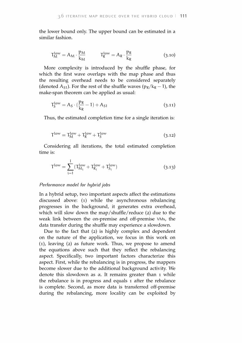
3.6 iterative map reduce over the hybrid cloud 111
the lower bound only. The upper bound can be estimated in asimilar fashion.
T lowM = AM ·pMkM
T lowR = AR ·pRkR
(3.10)
More complexity is introduced by the shuffle phase, forwhich the first wave overlaps with the map phase and thusthe resulting overhead needs to be considered separately(denoted AS1). For the rest of the shuffle waves (pR/kR − 1), themake-span theorem can be applied as usual:
T lowS = AS · (pRkR
− 1) +AS1 (3.11)
Thus, the estimated completion time for a single iteration is:
T low = T lowM + T lowR + T lowS (3.12)
Considering all iterations, the total estimated completiontime is:
T low =
I∑i=1
(T lowMi+ T lowRi + T lowSi ) (3.13)
Performance model for hybrid jobs
In a hybrid setup, two important aspects affect the estimationsdiscussed above: (1) while the asynchronous rebalancingprogresses in the background, it generates extra overhead,which will slow down the map/shuffle/reduce (2) due to theweak link between the on-premise and off-premise VMs, thedata transfer during the shuffle may experience a slowdown.
Due to the fact that (2) is highly complex and dependenton the nature of the application, we focus in this work on(1), leaving (2) as future work. Thus, we propose to amendthe equations above such that they reflect the rebalancingaspect. Specifically, two important factors characterize thisaspect. First, while the rebalancing is in progress, the mappersbecome slower due to the additional background activity. Wedenote this slowdown as α. It remains greater than 1 whilethe rebalance is in progress and equals 1 after the rebalanceis complete. Second, as more data is transferred off-premiseduring the rebalancing, more locality can be exploited by
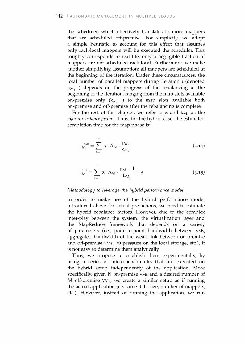
112 autonomic management in multiple clouds
the scheduler, which effectively translates to more mappersthat are scheduled off-premise. For simplicity, we adopta simple heuristic to account for this effect that assumesonly rack-local mappers will be executed the scheduler. Thisroughly corresponds to real life: only a negligible fraction ofmappers are not scheduled rack-local. Furthermore, we makeanother simplifying assumption: all mappers are scheduled atthe beginning of the iteration. Under these circumstances, thetotal number of parallel mappers during iteration i (denotedkMi
) depends on the progress of the rebalancing at thebeginning of the iteration, ranging from the map slots availableon-premise only (kM1
) to the map slots available bothon-premise and off-premise after the rebalancing is complete.
For the rest of this chapter, we refer to α and kMias the
hybrid rebalance factors. Thus, for the hybrid case, the estimatedcompletion time for the map phase is:
T lowM =
I∑i=1
α ·AM ·pMkMi
(3.14)
TupM =
I∑i=1
α ·AM ·pM − 1
kMi
+ λ (3.15)
Methodology to leverage the hybrid performance model
In order to make use of the hybrid performance modelintroduced above for actual predictions, we need to estimatethe hybrid rebalance factors. However, due to the complexinter-play between the system, the virtualization layer andthe MapReduce framework that depends on a varietyof parameters (i.e., point-to-point bandwidth between VMs,aggregated bandwidth of the weak link between on-premiseand off-premise VMs, I/O pressure on the local storage, etc.), itis not easy to determine them analytically.
Thus, we propose to establish them experimentally, byusing a series of micro-benchmarks that are executed onthe hybrid setup independently of the application. Morespecifically, given N on-premise VMs and a desired number ofM off-premise VMs, we create a similar setup as if runningthe actual application (i.e. same data size, number of mappers,etc.). However, instead of running the application, we run
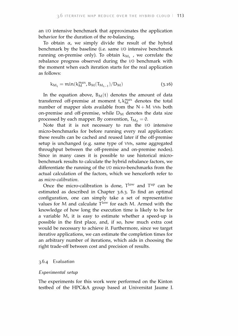
3.6 iterative map reduce over the hybrid cloud 113
an I/O intensive benchmark that approximates the applicationbehavior for the duration of the re-balancing.
To obtain α, we simply divide the result of the hybridbenchmark by the baseline (i.e. same I/O intensive benchmarkrunning on-premise only). To obtain kMi
, we correlate therebalance progress observed during the I/O benchmark withthe moment when each iteration starts for the real applicationas follows:
kMi= min(kmaxM ,BM(TMi−1
)/DM) (3.16)
In the equation above, BM(t) denotes the amount of datatransferred off-premise at moment t,kmaxM denotes the totalnumber of mapper slots available from the N+M VMs bothon-premise and off-premise, while DM denotes the data sizeprocessed by each mapper. By convention, TM0
= 0.Note that it is not necessary to run the I/O intensive
micro-benchmarks for before running every real application:these results can be cached and reused later if the off-premisesetup is unchanged (e.g. same type of VMs, same aggregatedthroughput between the off-premise and on-premise nodes).Since in many cases it is possible to use historical micro-benchmark results to calculate the hybrid rebalance factors, wedifferentiate the running of the I/O micro-benchmarks from theactual calculation of the factors, which we henceforth refer toas micro-calibration.
Once the micro-calibration is done, T low and Tup can beestimated as described in Chapter 3.6.3. To find an optimalconfiguration, one can simply take a set of representativevalues for M and calculate T low for each M. Armed with theknowledge of how long the execution time is likely to be fora variable M, it is easy to estimate whether a speed-up ispossible in the first place, and, if so, how much extra costwould be necessary to achieve it. Furthermore, since we targetiterative applications, we can estimate the completion times foran arbitrary number of iterations, which aids in choosing theright trade-off between cost and precision of results.
3.6.4 Evaluation
Experimental setup
The experiments for this work were performed on the Kintontestbed of the HPC&A group based at Universitat Jaume I.
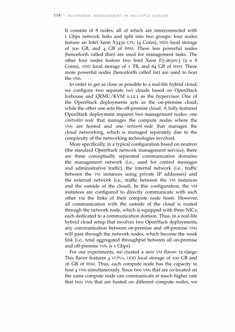
114 autonomic management in multiple clouds
It consists of 8 nodes, all of which are interconnected with1 Gbps network links and split into two groups: four nodesfeature an Intel Xeon X3430 CPU (4 Cores), HDD local storageof 500 GB, and 4 GB of RAM. These less powerful nodes(henceforth called thin) are used for management tasks. Theother four nodes feature two Intel Xeon E5-2630v3 (2 x 8
Cores), HDD local storage of 1 TB, and 64 GB of RAM. Thesemore powerful nodes (henceforth called fat) are used to hostthe VMs.
In order to get as close as possible to a real-life hybrid cloud,we configure two separate IaaS clouds based on OpenStackIcehouse and QEMU/KVM 0.12.1 as the hypervisor. One ofthe OpenStack deployments acts as the on-premise cloud,while the other one acts the off-premise cloud. A fully-featuredOpenStack deployment requires two management nodes: onecontroller node that manages the compute nodes where theVMs are hosted and one network node that manages thecloud networking, which is managed separately due to thecomplexity of the networking technologies involved.
More specifically, in a typical configuration based on neutron(the standard OpenStack network management service), thereare three conceptually separated communication domains:the management network (i.e., used for control messagesand administrative traffic), the internal network (i.e., trafficbetween the VM instances using private IP addresses) andthe external network (i.e., traffic between the VM instancesand the outside of the cloud). In this configuration, the VMinstances are configured to directly communicate with eachother via the links of their compute node hosts. However,all communication with the outside of the cloud is routedthrough the network node, which is equipped with three NICs,each dedicated to a communication domain. Thus, in a real-lifehybrid cloud setup that involves two OpenStack deployments,any communication between on-premise and off-premise VMswill pass through the network nodes, which become the weaklink (i.e., total aggregated throughput between all on-premiseand off-premise VMs is 1 Gbps).
For our experiments, we created a new VM flavor: i2.xlarge.This flavor features 4 VCPUs, HDD local storage of 100 GB and16 GB of RAM. Thus, each compute node has the capacity tohost 4 VMs simultaneously. Since two VMs that are co-located onthe same compute node can communicate at much higher ratethat two VMs that are hosted on different compute nodes, we
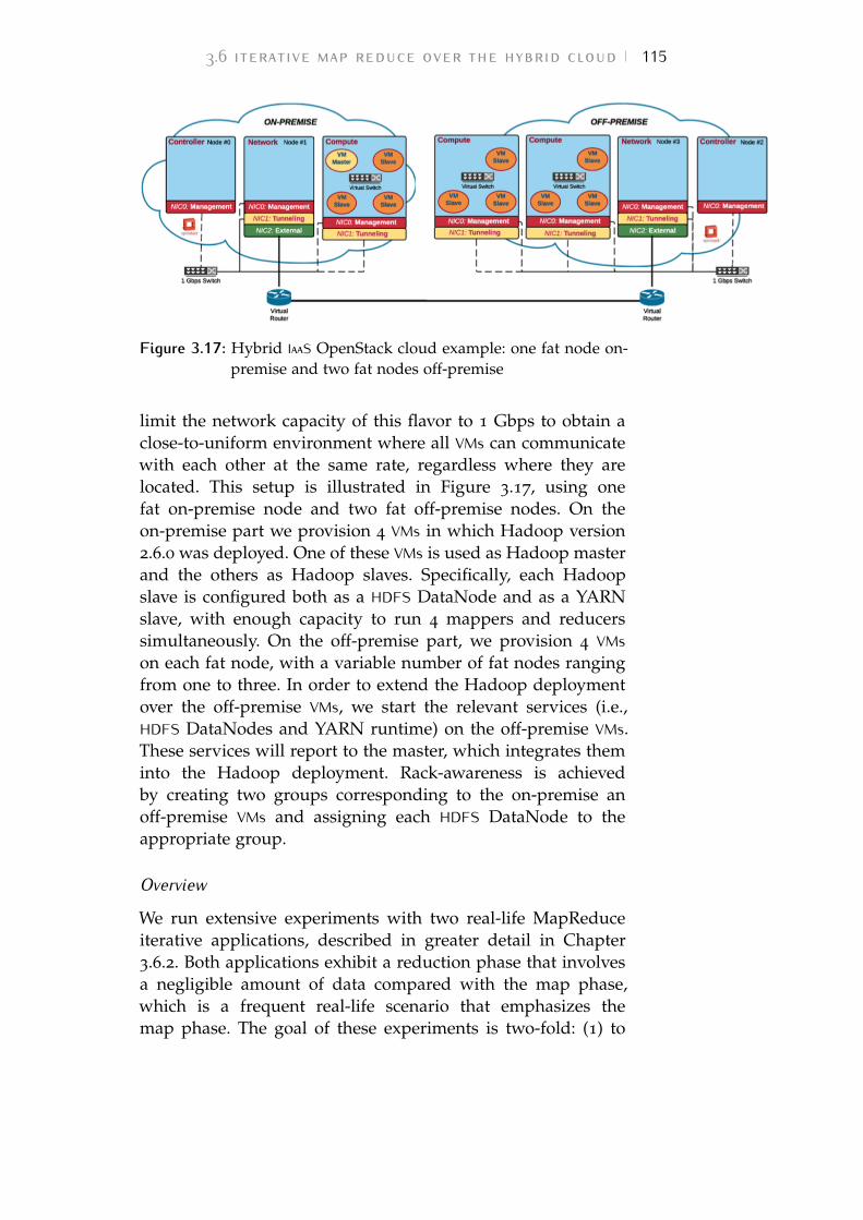
3.6 iterative map reduce over the hybrid cloud 115
Figure 3.17: Hybrid IaaS OpenStack cloud example: one fat node on-premise and two fat nodes off-premise
limit the network capacity of this flavor to 1 Gbps to obtain aclose-to-uniform environment where all VMs can communicatewith each other at the same rate, regardless where they arelocated. This setup is illustrated in Figure 3.17, using onefat on-premise node and two fat off-premise nodes. On theon-premise part we provision 4 VMs in which Hadoop version2.6.0 was deployed. One of these VMs is used as Hadoop masterand the others as Hadoop slaves. Specifically, each Hadoopslave is configured both as a HDFS DataNode and as a YARNslave, with enough capacity to run 4 mappers and reducerssimultaneously. On the off-premise part, we provision 4 VMson each fat node, with a variable number of fat nodes rangingfrom one to three. In order to extend the Hadoop deploymentover the off-premise VMs, we start the relevant services (i.e.,HDFS DataNodes and YARN runtime) on the off-premise VMs.These services will report to the master, which integrates theminto the Hadoop deployment. Rack-awareness is achievedby creating two groups corresponding to the on-premise anoff-premise VMs and assigning each HDFS DataNode to theappropriate group.
Overview
We run extensive experiments with two real-life MapReduceiterative applications, described in greater detail in Chapter3.6.2. Both applications exhibit a reduction phase that involvesa negligible amount of data compared with the map phase,which is a frequent real-life scenario that emphasizes themap phase. The goal of these experiments is two-fold: (1) to
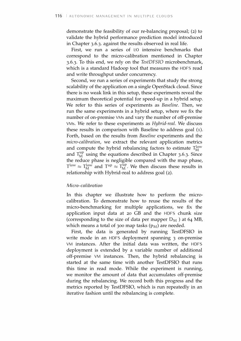
116 autonomic management in multiple clouds
demonstrate the feasibility of our re-balancing proposal; (2) tovalidate the hybrid performance prediction model introducedin Chapter 3.6.3. against the results observed in real life.
First, we run a series of I/O intensive benchmarks thatcorrespond to the micro-calibration mentioned in Chapter3.6.3. To this end, we rely on the TestDFSIO microbenchmark,which is a standard Hadoop tool that measures the HDFS readand write throughput under concurrency.
Second, we run a series of experiments that study the strongscalability of the application on a single OpenStack cloud. Sincethere is no weak link in this setup, these experiments reveal themaximum theoretical potential for speed-up in a hybrid setup.We refer to this series of experiments as Baseline. Then, werun the same experiments in a hybrid setup, where we fix thenumber of on-premise VMs and vary the number of off-premiseVMs. We refer to these experiments as Hybrid-real. We discussthese results in comparison with Baseline to address goal (1).Forth, based on the results from Baseline experiments and themicro-calibration, we extract the relevant application metricsand compute the hybrid rebalancing factors to estimate T lowMand TupM using the equations described in Chapter 3.6.3. Sincethe reduce phase is negligible compared with the map phase,T low ≈ T lowM and Tup ≈ TupM . We then discuss these results inrelationship with Hybrid-real to address goal (2).
Micro-calibration
In this chapter we illustrate how to perform the micro-calibration. To demonstrate how to reuse the results of themicro-benchmarking for multiple applications, we fix theapplication input data at 20 GB and the HDFS chunk size(corresponding to the size of data per mapper DM ) at 64 MB,which means a total of 300 map tasks (pM) are needed.
First, the data is generated by running TestDFSIO inwrite mode in an HDFS deployment spanning 3 on-premiseVM instances. After the initial data was written, the HDFSdeployment is extended by a variable number of additionaloff-premise VM instances. Then, the hybrid rebalancing isstarted at the same time with another TestDFSIO that runsthis time in read mode. While the experiment is running,we monitor the amount of data that accumulates off-premiseduring the rebalancing. We record both this progress and themetrics reported by TestDFSIO, which is run repeatedly in aniterative fashion until the rebalancing is complete.
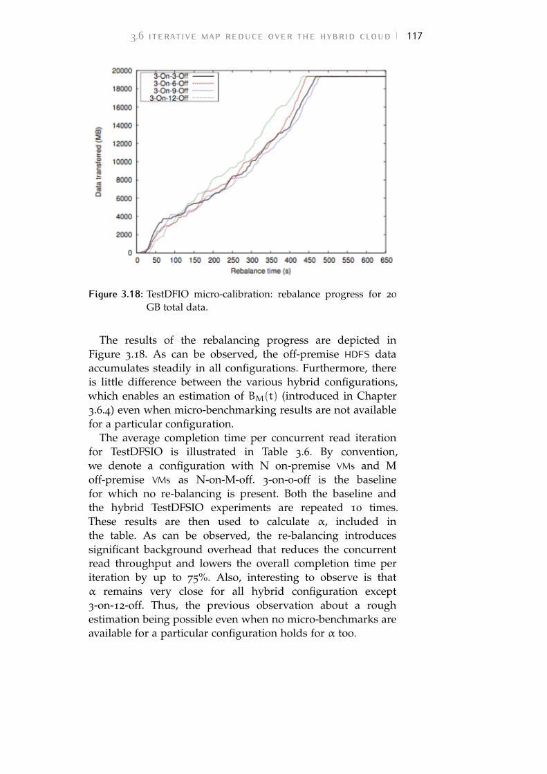
3.6 iterative map reduce over the hybrid cloud 117
Figure 3.18: TestDFIO micro-calibration: rebalance progress for 20
GB total data.
The results of the rebalancing progress are depicted inFigure 3.18. As can be observed, the off-premise HDFS dataaccumulates steadily in all configurations. Furthermore, thereis little difference between the various hybrid configurations,which enables an estimation of BM(t) (introduced in Chapter3.6.4) even when micro-benchmarking results are not availablefor a particular configuration.
The average completion time per concurrent read iterationfor TestDFSIO is illustrated in Table 3.6. By convention,we denote a configuration with N on-premise VMs and Moff-premise VMs as N-on-M-off. 3-on-0-off is the baselinefor which no re-balancing is present. Both the baseline andthe hybrid TestDFSIO experiments are repeated 10 times.These results are then used to calculate α, included inthe table. As can be observed, the re-balancing introducessignificant background overhead that reduces the concurrentread throughput and lowers the overall completion time periteration by up to 75%. Also, interesting to observe is thatα remains very close for all hybrid configuration except3-on-12-off. Thus, the previous observation about a roughestimation being possible even when no micro-benchmarks areavailable for a particular configuration holds for α too.
118 autonomic management in multiple clouds
Configuration Time / iteration α
3-on-0-off 276s N/A
3-on-3-off 472s 1.70
3-on-6-off 471s 1.70
3-on-9-off 485s 1.75
3-on-12-off 416s 1.5Table 3.6: TestDFSIO Agerage completion time per iteration
KMeans
Our next series of experiments focus on K-Means [116],a widely used application in a multitude of contexts:vector quantization in signal processing, cluster analysis indata mining, pattern classification and feature extractionfor machine learning, etc. K-Means partitions a set ofmultidimensional vectors into k sets, such that the sum ofsquares of distances between all vectors from the same setand their mean is minimized. This is typically done by usingiterative refinement: at each step the new means are calculatedbased on the results from the previous iteration, until theyremain unchanged (with respect to a small epsilon). K-Meanswas shown to be efficiently parallelizable and scales well usingMapReduce [117], which makes it a popular tool to analyzelarge quantities of data at large scale.
For the purpose of this work, we use the MapReduceK-Means implementation that is part of the Mahout 0.10
collection of machine learning algorithms. This implementationgenerates only a minimal amount of intermediate data at eachiteration (i.e., the mean for each of the k sets), however ittypically analyses a large amount of input data that remainsunchanged between the iterations. Thus, it is classified as amap-intensive job. We generate 20 GB worth of input that isprocessed in 10 iterations. The data is generated using the datagenerator included in Mahout and is uploaded to HDFS beforestarting each experiment. For comparison, the shuffle data foreach iteration is in the order of several MB, which is why wecan consider the reduction phase negligible (i.e., T low ≈ T lowMand Tup ≈ TupM ).
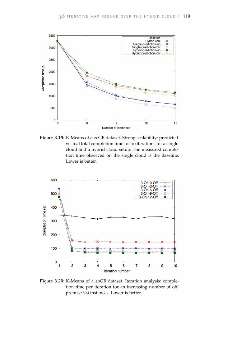
3.6 iterative map reduce over the hybrid cloud 119
Figure 3.19: K-Means of a 20GB dataset. Strong scalability: predictedvs. real total completion time for 10 iterations for a singlecloud and a hybrid cloud setup. The measured comple-tion time observed on the single cloud is the Baseline.Lower is better.
Figure 3.20: K-Means of a 20GB dataset. Iteration analysis: comple-tion time per iteration for an increasing number of off-premise VM instances. Lower is better.
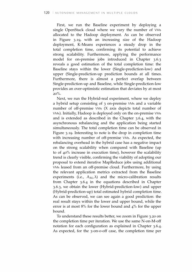
120 autonomic management in multiple clouds
First, we run the Baseline experiment by deploying asingle OpenStack cloud where we vary the number of VMsallocated to the Hadoop deployment. As can be observedin Figure 3.19, with an increasing size of the Hadoopdeployment, K-Means experiences a steady drop in thetotal completion time, confirming its potential to achievestrong scalability. Furthermore, applying the performancemodel for on-premise jobs introduced in Chapter 3.6.3reveals a good estimation of the total completion time: theBaseline stays within the lower (Single-prediction-low) andupper (Single-prediction-up prediction bounds at all times.Furthermore, there is almost a perfect overlap betweenSingle-prediction-up and Baseline, while Single-prediction-lowprovides an over-optimistic estimation that deviates by at most20%.
Next, we run the Hybrid-real experiment, where we deploya hybrid setup consisting of 3 on-premise VMs and a variablenumber of off-premise VMs (X axis depicts total number ofVMs). Initially, Hadoop is deployed only on the on-premise VMsand is extended as described in the Chapter 3.6.4, with theasynchronous rebalancing and the application being startedsimultaneously. The total completion time can be observed inFigure 3.19. Interesting to note is the drop in completion timewith increasing number of off-premise VMs. As expected, therebalancing overhead in the hybrid case has a negative impacton the strong scalability when compared with Baseline (upto of 40% increase in execution time), however the scalabilitytrend is clearly visible, confirming the viability of adopting ourproposal to extend iterative MapReduce jobs using additionalVMs leased from an off-premise cloud. Furthermore, by usingthe relevant application metrics extracted from the Baselineexperiments (i.e., AM, λ) and the micro-calibration resultsfrom Chapter 3.6.4 in the equations described in Chapter3.6.3, we obtain the lower (Hybrid-prediction-low) and upper(Hybrid-prediction-up) total estimated hybrid completion time.As can be observed, we can see again a good prediction: thereal result stays within the lower and upper bound, while theerror is at most 8% for the lower bound and 4% for the upperbound.
To understand these results better, we zoom in Figure 3.20 onthe completion time per iteration. We use the same N-on-M-offnotation for each configuration as explained in Chapter 3.6.4.As expected, for the 3-on-0-off case, the completion time per
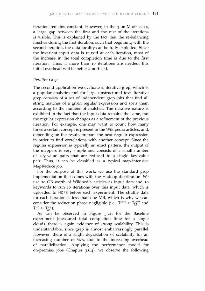
3.6 iterative map reduce over the hybrid cloud 121
iteration remains constant. However, in the 3-on-M-off cases,a large gap between the first and the rest of the iterationsis visible. This is explained by the fact that the re-balancingfinishes during the first iteration, such that beginning with thesecond iteration, the data locality can be fully exploited. Sincethe invariant input data is reused at each iteration, most ofthe increase in the total completion time is due to the firstiteration. Thus, if more than 10 iterations are needed, thisinitial overhead will be better amortized.
Iterative Grep
The second application we evaluate is iterative grep, which isa popular analytics tool for large unstructured text. Iterativegrep consists of a set of independent grep jobs that find allstring matches of a given regular expression and sorts themaccording to the number of matches. The iterative nature isexhibited in the fact that the input data remains the same, butthe regular expression changes as a refinement of the previousiteration. For example, one may want to count how manytimes a certain concept is present in the Wikipedia articles, and,depending on the result, prepare the next regular expressionin order to find correlations with another concept. Since theregular expression is typically an exact pattern, the output ofthe mappers is very simple and consists of a small numberof key-value pairs that are reduced to a single key-valuepair. Thus, it can be classified as a typical map-intensiveMapReduce job.
For the purpose of this work, we use the standard grepimplementation that comes with the Hadoop distribution. Weuse 20 GB worth of Wikipedia articles as input data and 10
keywords to run 10 iterations over this input data, which isuploaded to HDFS before each experiment. The shuffle datafor each iteration is less than one MB, which is why we canconsider the reduction phase negligible (i.e., T low ≈ T lowM andTup ≈ TupM ).
As can be observed in Figure 3.21, for the Baselineexperiment (measured total completion time for a singlecloud), there is again evidence of strong scalability. This isunderstandable, since grep is almost embarrassingly parallel.However, there is a slight degradation of scalability for anincreasing number of VMs, due to the increasing overheadof parallelization. Applying the performance model foron-premise jobs (Chapter 3.6.4), we observe the following
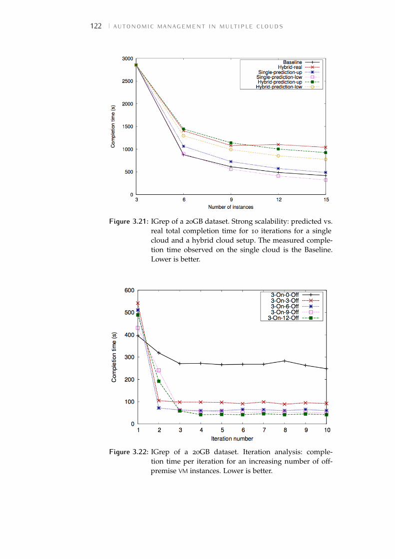
122 autonomic management in multiple clouds
Figure 3.21: IGrep of a 20GB dataset. Strong scalability: predicted vs.real total completion time for 10 iterations for a singlecloud and a hybrid cloud setup. The measured comple-tion time observed on the single cloud is the Baseline.Lower is better.
Figure 3.22: IGrep of a 20GB dataset. Iteration analysis: comple-tion time per iteration for an increasing number of off-premise VM instances. Lower is better.
3.6 iterative map reduce over the hybrid cloud 123
estimations for the total completion time: the lower bound(Single-prediction-low) under-estimates by up to 24% and theupper bound over-estimates by up to 15%, which places themeasured total completion time within the lower and upperbound.
For the Hybrid-real experiment, we deploy a hybrid setupthat keeps 3 on-premise VMs and adds a variable number ofoff-premise VMs. The total completion time can be observedin Figure 3.21 (total number of VMs on X axis). Again, weobserve a drop in completion time with increasing numberof off-premise VMs, which confirms the viability of adoptingour re-balancing proposal. Furthermore, the lower (Hybrid-prediction-low) and upper (Hybrid-prediction-up) estimatedhybrid completion time keep the measured result within theirlimits up until 6 off-premise VMs. However, when increasingthe number of off-premise VMs beyond 6, both the lower andupper bound under-estimate the measured completion time:by up to 25% and 12% respectively.
These results are better understood by analyzing the periteration completion times, which are depicted in Figure 3.22.Surprisingly, for the 3-on-0-off case, the completion time periteration remains constant only after a few iterations, whichhints at possible OS caching effects for the input data readfrom HDFS at each iteration. In the hybrid configurations, itcan be observed that the rebalancing does not finish during thefirst iteration for the case when a large number of off-premiseVMs is used (i.e. 9 and 12). This increased complexity mayexplain why the hybrid estimations exhibit larger errors thanin the case of K-Means. In fact, when compared with thesingle cloud estimations, it can be observed that the errors aresimilar in magnitude, which hints that the hybrid aspect wasaccurately factored into the estimation.
3.6.5 Discussion
This work contributed to the autonomic management of VMsover hybrid clouds with a novel proposal that addressesthis challenge for iterative MapReduce applications. Ittransparently manages data movements asynchronously in anefficient fashion without invasive changes to the MapReduceframework or the underlying storage layer. At the same time,it is able to predict the runtime of the application for a varietyof hybrid configurations, by combining analytical modeling
124 autonomic management in multiple clouds
with micro-calibration. The results using two real-life iterativeMapReduce applications show excellent hybrid scalabilitypotential that follows a similar trend as the single-sitescalability except for an initial overhead during the first fewiterations, whose impact on the overall execution time isdiminished with increasing number of iterations.
Furthermore, our prediction of the execution time for ahybrid setup matches the accuracy of the techniques used insingle-site setups, with maximum upper/lower bound errorsof 4%/8% and, respectively, 12%/25%.
Encouraged by these results, we plan to broaden the scopeof our work in future efforts. In particular, we focusedon map-intensive applications where the reduce phase isnegligible in comparison. Thus, one interesting directionis to complement the current work with an analysis ofreduce-intensive jobs in a hybrid setup: study of the weaklink and interferences with the rebalancing, refined predictionequations, etc.
3.7 conclusions and future workIn this chapter we highlighted the numerous kinds of cloudinteroperability scenarios and we particularly focused on thehybrid environment as a promising mechanism to leverageboth on-premise private and off-premise public clouds.
Hybrid cloud opens an entire new horizon in the big dataanalytics landscape, effectively enabling on-premise resourceowners to extend complex workloads beyond the capacity oftheir infrastructure by leasing off-premise resources. However,the need to transfer large data sizes from the IC towardoff-premise through a higher latency medium poses a difficultchallenge to the ability to exploit data locality efficiently.
In this scenario, the infrastructure management must becombined with a sapient application-level strategy to transferoff-premise the minimum amount of data that enable aconsistent off-premise computation without saturating thelimited inter-cloud bandwidth.
This work particularly focused on MapReduce applicationsand contributed to the autonomic hybrid infrastructuremanagement in this field by proposing a layered frameworkarchitecture to enable the dynamic provisioning and
3.7 conclusions and future work 125
configuration of off-premise VMs that extend the capacity ofthe private cloud.
We also proposed two different policies (SPAN and HyMR)to enable the execution of a classical MapReduce job whenon-premise physical machines are in a stressed conditionand a solution to boost iterative MapReduce leveraging theoff-premise resources.
The proposed layered architecture needs to be extended andadapted to OCCI standards [105], in order to further improvethe system interoperability with other cloud platforms.
As the map phase generally has a simpler and morestandardizable execution schema when compared to thereduce phase – thanks to the possibility to leverage more thedata locality –, several works in this field focus on the analysisand performance prediction of the mappers. Nevertheless, thestate of the art would benefit from studying of the reducephase in a hybrid setup. Therefore, the prediction model inChapter 3.6 needs to be extended/refined to evaluate theperformance of reduce-intensive jobs when some of the dataare transferred through a limited bandwidth.
Finally, considering a classic MapReduce computation overhybrid cloud, the management policies depicted in Chapters3.4 and 3.5 would benefit from the definition of a morecomplex strategy to anticipate the identification of a stressingcondition going to occur on the physical nodes. For this reason,in the next chapter, we overlook the information about thecurrent utilization level of physical machine resources (comingfor the monitoring component of our management system)and focus on what can be inferred by analyzing the runtimebehavior of the application.

4 M O N I TO R I N G T H EA R C H I T E C T U R E W I T HP R O C E S S M I N I N GDistributed architectures, such as MapReduce, are providing
technical answers to the challenge of big data analytics.Especially when coupled with a cloud infrastructure, thesesolutions can be enriched of additional features, such asthe dynamic provisioning of computational nodes – e.g., toensure that processing tasks are performed within a temporaldeadline or to deal with data peaks. As deepen in the previouschapters, good results can be achieved at infrastructure levelby monitoring the resource utilization and spawning new VMs– eventually on an off-premise public cloud – to boost theexecution.
Nevertheless, the factors that can slow down a MapReducecomputation are not only related to the limited amount ofresources available but they can also be connected with thespecificities of the infrastructure configuration or processeddata itself. For example, the time to execute a MapReducejob on the same volume of data can vary depending on thepercentage of data local computation obtainable, the qualityof the link between the computing nodes, the content of theprocessed data itself, etc.
For this reason, the autonomic management of a (hybrid)cloud infrastructure can also benefit from the implementationof advanced monitoring systems taking into account not onlythe physical resource utilization, but also domain specificinformation derived by the application level computation.
The applicative software running over the cloud is anexample of system that must comply to a set of contract termsand functional and non-functional requirements specified by aSLA. The complexity of the resulting overall system, as well asthe dynamism and flexibility of the involved processes, oftenrequire an on-line operational support checking compliance.Such monitor should detect when the overall system deviatesfrom the expected behavior, and raise an alert notificationimmediately, possibly suggesting/executing specific recoveryactions. This run-time monitoring/verification aspect – i.e. thecapability of determining during the execution if the system
127
128 monitoring the architecture with process mining
exhibits some particular behavior, possibly compliance withthe process model we have in mind – is still matter of anintense research effort in the emergent Process Mining [118]area. As pointed out by Van Der Aalst et al. in [118], applyingProcess Mining techniques in such an online setting createsadditional challenges in terms of computing power and dataquality.
Starting point for Process Mining is an event log. We assumethat in the architecture going to be analyzed it is possible tosequentially record events. Each event refers to an activity (i.e.,a well-defined step in some process/task) and it is related to aparticular process instance. Note that, in case of a distributedcomputation, we also need extra information such as, forinstance, the resource/node executing, initiating and finishingthe process/task, the timestamp of the event, or other dataelements.
While, in an cloud architecture, several tools exists forperforming a generic, low-level monitoring task [110, 119],we advocate also the use of an application/process orientedmonitoring tool in the context of Process Mining in orderto run-time check the conformance of the overall system.Essentially, the goal of the work presented in this chapteris to apply the well-known Process Mining techniques tothe monitoring of complex distributed applications, such asMapReduce in a cloud environment.
As suggested by the previous chapters, if we assume that theperformance of the overall computing infrastructure is stableand a minimum QoS is guaranteed, MapReduce parallelizationmodel makes relatively simple to estimate a job executiontime by on-line checking the execution time of each task inwhich the application has been split. This estimation can becompared to the deadline and used to predict the need forscaling the architecture [79, 88, 100].
Nevertheless, the initial assumptions may be not alwayssatisfied and the execution time may differ from what expecteddepending on either architectural factors (e.g., the variability inthe performance of the machines involved in the computationor the fluctuation of the bandwidth between the nodes), ordomain-specific factors (e.g., a task is slowed down due to theinput data content or location). This unpredictable behaviorcould be run-time corrected if the execution relays on anelastic set of computational resources as that provided bycloud computing systems.
monitoring the architecture with process mining 129
In this chapter, we focus on the step of monitoringMapReduce applications, to detect situations where additionalresources are needed to meet the deadlines. To this end, weexploit some techniques and tools developed in the researchfield of Business Process Management [120]: in particular, wefocus on declarative languages and tools for monitoring theexecution of business processes. Inside SHYAM framework, weintroduce a logic-based monitor able to detect possible delays,and trigger recovery actions such as the dynamic provisioningof further resources.
Since MapReduce applications typically operate in dynamic,complex and interconnected environments demanding highflexibility, a detailed and complete description of their behaviorseems to be very difficult, while the elicitation of the (minimal)set of behavioral constraints/properties that must be respectedto correctly execute the process, and that cannot be directlyincorporated at design time into the system can be morerealistic and useful.
Therefore, in this context, we will adopt the Event Calculus[121], logic-based formalism for representing actions and theireffects, in particular we relay on a verification frameworkbased on constraints, called Mobucon EC (Monitoringbusiness constraints with Event Calculus [122]), able todynamically monitor streams of events characterizing theprocess executions (i.e., running cases) and check whetherthe constraints of interest are currently satisfied or not.Mobucon is an extension of the constraint-based Declarelanguage [123] and is data aware. It allows us to specifyproperties of the system to be monitored using a logic-basedsyntax involving time constraints and task data. The EventCalculus formalization has been proven a successful choice fordealing with runtime verification and monitoring, thanks to itshigh expressiveness and the existence of reactive, incrementalreasoners [122].
This chapter presents an on-line monitoring system to checkthe compliance of each node of a distributed infrastructurefor data processing running on a cloud environment. Theresulting information is used for taking scaling decisionsand dynamically recovering from critical situations with abest effort approach by means of an underlying previouslyimplemented infrastructure layer. This could be consideredas a first step towards a MapReduce engine with autonomicfeatures either in run-time detecting undesired task behaviors,
130 monitoring the architecture with process mining
or in handling such events with dynamic provisioning ofcomputational resources in an hybrid cloud scenario.
Chapter 4.1 provides a first introduction to the EventCalculus formalization and Mobucon framework. Later, inChapter 4.2, we describe the implemented architecture indetail, while in Chapter 4.3, we focus on the data-intensiveuse case scenario and we provide a first evaluation of theperformance of our contribution. Chapter 4.4 summarize thenovelties introduced by our approach and suggests futurerelated work. The content of this chapter is also presented inthe work [124].
4.1 positioning our contributionAs regards the use of Event Calculus for verification andmonitoring, several examples can be found in litterature indifferent application domains but we are not aware of anywork applying it to the monitoring of MapReduce jobs in acloud environment. Event Calculus has been used in variousfields to verify the compliance of a system to user-definedbehavioral properties. For example, [125], [126] exploit ad-hocevent processing algorithms to manipulate events and fluents,written in JAVA. Differently from Mobucon , they do not havean underlying formal basis, and they cannot take advantageof the expressiveness and computational power of logicprogramming.
Several authors – [127], [128] – have investigated the use oftemporal logics – Linear Temporal Logic (LTL) in particular – asa declarative language for specifying properties to be verifiedat runtime. Nevertheless, these approaches lack the supportof quantitative time constraints, non-atomic activities withidentifier-based correlation, and data-aware conditions. Thesecharacteristics – supported by Mobucon – are instead veryimportant in our application domain.
Our approach takes inspiration from the work by Mattess etal. [88], which presents an online provisioning policy to meet adeadline for the Map phase. In order to check the complianceof the application, [88] takes into account the execution timeof each map tasks but, differently from our approach, thedeadline compliance prediction for the Map phase is computedwith a traditional approach to monitoring, which introducescomplexity in the implementation and tuning, whereas our
4.2 mapreduce auto-scaling engine 131
solution can benefit from a simple enunciation of the systemproperties relaying on the declarative approach offered byMobucon .
4.2 mapreduce auto-scaling engineWe relay on HyIaaS system presented in Chapter 3.3 to developMapReduce Auto-scaling Engine, an application-level softwarecomponent to online detect user-defined critical situationsin a MapReduce environment. The resulting frameworkarchitecture autonomously react by providing or removingresources according to high-level rules definable in declarativelanguage.
consists of three main subcomponents (grey blocks in Figure4.1): the Monitoring, Recovery and Platform Interface. Theseelements interacts with the MapReduce platform to detect andreact to anomalous sequences of events in the execution flow.
The Monitoring component takes as input a high-levelspecification of the system properties describing the expectedbehavior of a MapReduce workflow and the on-line sequenceof events from the MapReduce platform’s log. Given theseinput data, the Monitoring component is able to rise alertswhenever the execution flow violates user-defined constraints.The alarms are evaluated by the Recovery component inorder to estimate how many computational nodes must beprovisioned (or de-provisioned) to face the critical conditionaccording to user-defined rules taken as input.
Finally, the Platform Interface is in charge of translatingthe requests for new MapReduce nodes into VM provisioningrequests to the infrastructure manager. The Platform Interfaceis also responsible for the installation of MapReduce-specificsoftware on the newly provided VMs. The output of thissubcomponent is a new configuration of the computing clusterwith a different number of working nodes.
As shown in Figure 4.1, MapReduce Auto-scaling Enginerelays HyIaaS component presented in Chapter 3.3 for theprovisioning of VMs [113]. This layer encapsulates the cloudfunctionality and interacts with different infrastructures torealize a hybrid cloud: if the resources of the company-ownedcloud are no longer enough, HyIaaS redirects the scale-uprequest to an off-premise public cloud. Therefore, thanks to
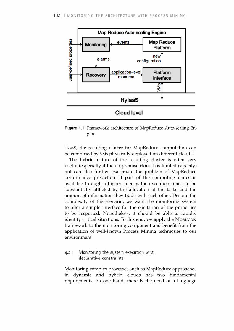
132 monitoring the architecture with process mining
Figure 4.1: Framework architecture of MapReduce Auto-scaling En-gine
HyIaaS, the resulting cluster for MapReduce computation canbe composed by VMs physically deployed on different clouds.
The hybrid nature of the resulting cluster is often veryuseful (especially if the on-premise cloud has limited capacity)but can also further exacerbate the problem of MapReduceperformance prediction. If part of the computing nodes isavailable through a higher latency, the execution time can besubstantially afflicted by the allocation of the tasks and theamount of information they trade with each other. Despite thecomplexity of the scenario, we want the monitoring systemto offer a simple interface for the elicitation of the propertiesto be respected. Nonetheless, it should be able to rapidlyidentify critical situations. To this end, we apply the Mobucon
framework to the monitoring component and benefit from theapplication of well-known Process Mining techniques to ourenvironment.
4.2.1 Monitoring the system execution w.r.t.declarative constraints
Monitoring complex processes such as MapReduce approachesin dynamic and hybrid clouds has two fundamentalrequirements: on one hand, there is the need of a language
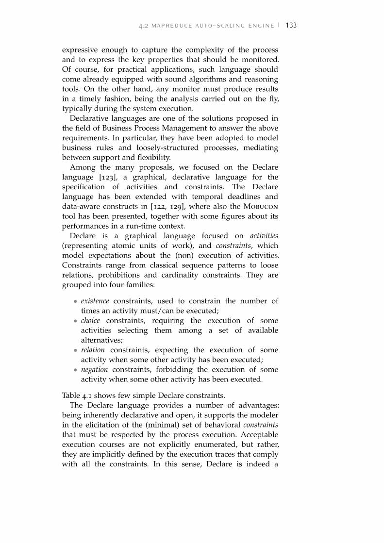
4.2 mapreduce auto-scaling engine 133
expressive enough to capture the complexity of the processand to express the key properties that should be monitored.Of course, for practical applications, such language shouldcome already equipped with sound algorithms and reasoningtools. On the other hand, any monitor must produce resultsin a timely fashion, being the analysis carried out on the fly,typically during the system execution.
Declarative languages are one of the solutions proposed inthe field of Business Process Management to answer the aboverequirements. In particular, they have been adopted to modelbusiness rules and loosely-structured processes, mediatingbetween support and flexibility.
Among the many proposals, we focused on the Declarelanguage [123], a graphical, declarative language for thespecification of activities and constraints. The Declarelanguage has been extended with temporal deadlines anddata-aware constructs in [122, 129], where also the Mobucon
tool has been presented, together with some figures about itsperformances in a run-time context.
Declare is a graphical language focused on activities(representing atomic units of work), and constraints, whichmodel expectations about the (non) execution of activities.Constraints range from classical sequence patterns to looserelations, prohibitions and cardinality constraints. They aregrouped into four families:
• existence constraints, used to constrain the number oftimes an activity must/can be executed;• choice constraints, requiring the execution of some
activities selecting them among a set of availablealternatives;• relation constraints, expecting the execution of some
activity when some other activity has been executed;• negation constraints, forbidding the execution of some
activity when some other activity has been executed.
Table 4.1 shows few simple Declare constraints.The Declare language provides a number of advantages:
being inherently declarative and open, it supports the modelerin the elicitation of the (minimal) set of behavioral constraintsthat must be respected by the process execution. Acceptableexecution courses are not explicitly enumerated, but rather,they are implicitly defined by the execution traces that complywith all the constraints. In this sense, Declare is indeed a
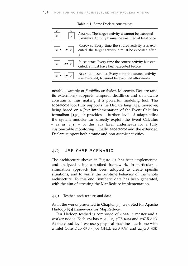
134 monitoring the architecture with process mining
Table 4.1: Some Declare constraints
0
a1..∗
b Absence The target activity a cannot be executedExistence Activity b must be executed at least once
a •−−−I bResponse Every time the source activity a is exe-cuted, the target activity b must be executed aftera
a −−−I• b Precedence Every time the source activity b is exe-cuted, a must have been executed before
a •−−−I‖ b Negation response Every time the source activitya is executed, b cannot be executed afterwards
notable example of flexibility by design. Moreover, Declare (andits extensions) supports temporal deadlines and data-awareconstraints, thus making it a powerful modeling tool. TheMobucon tool fully supports the Declare language; moreover,being based on a Java implementation of the Event Calculusformalism [130], it provides a further level of adaptability:the system modeler can directly exploit the Event Calculus– as in [131] – or the Java layer underneath for a fullycustomizable monitoring. Finally, Mobucon and the extendedDeclare support both atomic and non-atomic activities.
4.3 use case scenarioThe architecture shown in Figure 4.1 has been implementedand analyzed using a testbed framework. In particular, asimulation approach has been adopted to create specificsituations, and to verify the run-time behavior of the wholearchitecture. To this end, synthetic data has been generated,with the aim of stressing the MapReduce implementation.
4.3.1 Testbed architecture and data
As in the works presented in Chapter 3.3, we opted for ApacheHadoop [59] framework for MapReduce.
Our Hadoop testbed is composed of 4 VMs: 1 master and 3
worker nodes. Each VM has 2 VCPUs, 4GB RAM and 20GB disk.At the cloud level we use 5 physical machines, each one witha Intel Core Duo CPU (3.06 GHz), 4GB RAM and 225GB HDD.
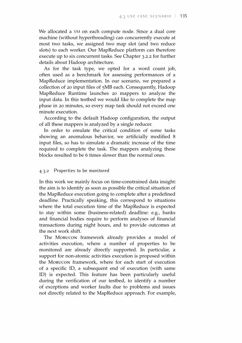
4.3 use case scenario 135
We allocated a VM on each compute node. Since a dual coremachine (without hyperthreading) can concurrently execute atmost two tasks, we assigned two map slot (and two reduceslots) to each worker. Our MapReduce platform can thereforeexecute up to six concurrent tasks. See Chapter 3.2.2 for furtherdetails about Hadoop architecture.
As for the task type, we opted for a word count job,often used as a benchmark for assessing performances of aMapReduce implementation. In our scenario, we prepared acollection of 20 input files of 5MB each. Consequently, HadoopMapReduce Runtime launches 20 mappers to analyze theinput data. In this testbed we would like to complete the mapphase in 20 minutes, so every map task should not exceed oneminute execution.
According to the default Hadoop configuration, the outputof all these mappers is analyzed by a single reducer.
In order to emulate the critical condition of some tasksshowing an anomalous behavior, we artificially modified 8
input files, so has to simulate a dramatic increase of the timerequired to complete the task. The mappers analyzing theseblocks resulted to be 6 times slower than the normal ones.
4.3.2 Properties to be monitored
In this work we mainly focus on time-constrained data insight:the aim is to identify as soon as possible the critical situation ofthe MapReduce execution going to complete after a predefineddeadline. Practically speaking, this correspond to situationswhere the total execution time of the MapReduce is expectedto stay within some (business-related) deadline: e.g., banksand financial bodies require to perform analyses of financialtransactions during night hours, and to provide outcomes atthe next work shift.
The Mobucon framework already provides a model ofactivities execution, where a number of properties to bemonitored are already directly supported. In particular, asupport for non-atomic activities execution is proposed withinthe Mobucon framework, where for each start of executionof a specific ID, a subsequent end of execution (with sameID) is expected. This feature has been particularly usefulduring the verification of our testbed, to identify a numberof exceptions and worker faults due to problems and issuesnot directly related to the MapReduce approach. For example,
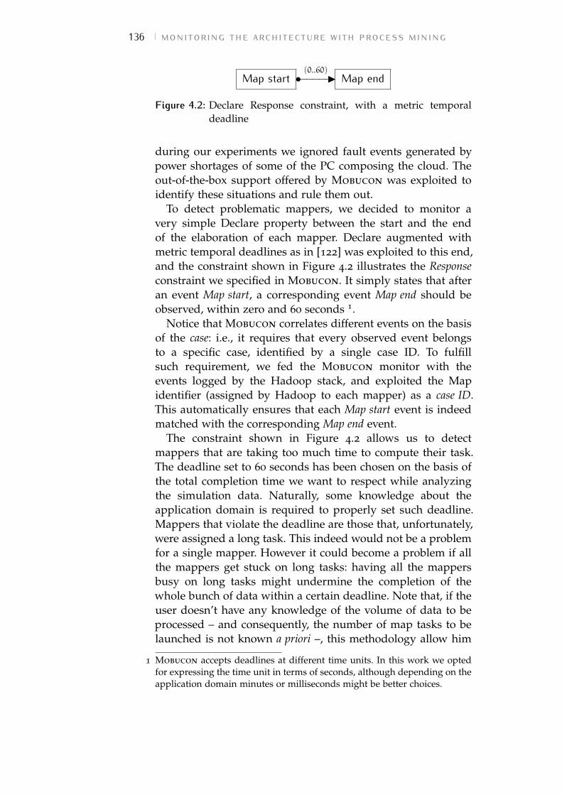
136 monitoring the architecture with process mining
Map start(0..60)•−−−−−I Map end
Figure 4.2: Declare Response constraint, with a metric temporaldeadline
during our experiments we ignored fault events generated bypower shortages of some of the PC composing the cloud. Theout-of-the-box support offered by Mobucon was exploited toidentify these situations and rule them out.
To detect problematic mappers, we decided to monitor avery simple Declare property between the start and the endof the elaboration of each mapper. Declare augmented withmetric temporal deadlines as in [122] was exploited to this end,and the constraint shown in Figure 4.2 illustrates the Responseconstraint we specified in Mobucon. It simply states that afteran event Map start, a corresponding event Map end should beobserved, within zero and 60 seconds 1.
Notice that Mobucon correlates different events on the basisof the case: i.e., it requires that every observed event belongsto a specific case, identified by a single case ID. To fulfillsuch requirement, we fed the Mobucon monitor with theevents logged by the Hadoop stack, and exploited the Mapidentifier (assigned by Hadoop to each mapper) as a case ID.This automatically ensures that each Map start event is indeedmatched with the corresponding Map end event.
The constraint shown in Figure 4.2 allows us to detectmappers that are taking too much time to compute their task.The deadline set to 60 seconds has been chosen on the basis ofthe total completion time we want to respect while analyzingthe simulation data. Naturally, some knowledge about theapplication domain is required to properly set such deadline.Mappers that violate the deadline are those that, unfortunately,were assigned a long task. This indeed would not be a problemfor a single mapper. However it could become a problem if allthe mappers get stuck on long tasks: having all the mappersbusy on long tasks might undermine the completion of thewhole bunch of data within a certain deadline. Note that, if theuser doesn’t have any knowledge of the volume of data to beprocessed – and consequently, the number of map tasks to belaunched is not known a priori –, this methodology allow him
1 Mobucon accepts deadlines at different time units. In this work we optedfor expressing the time unit in terms of seconds, although depending on theapplication domain minutes or milliseconds might be better choices.
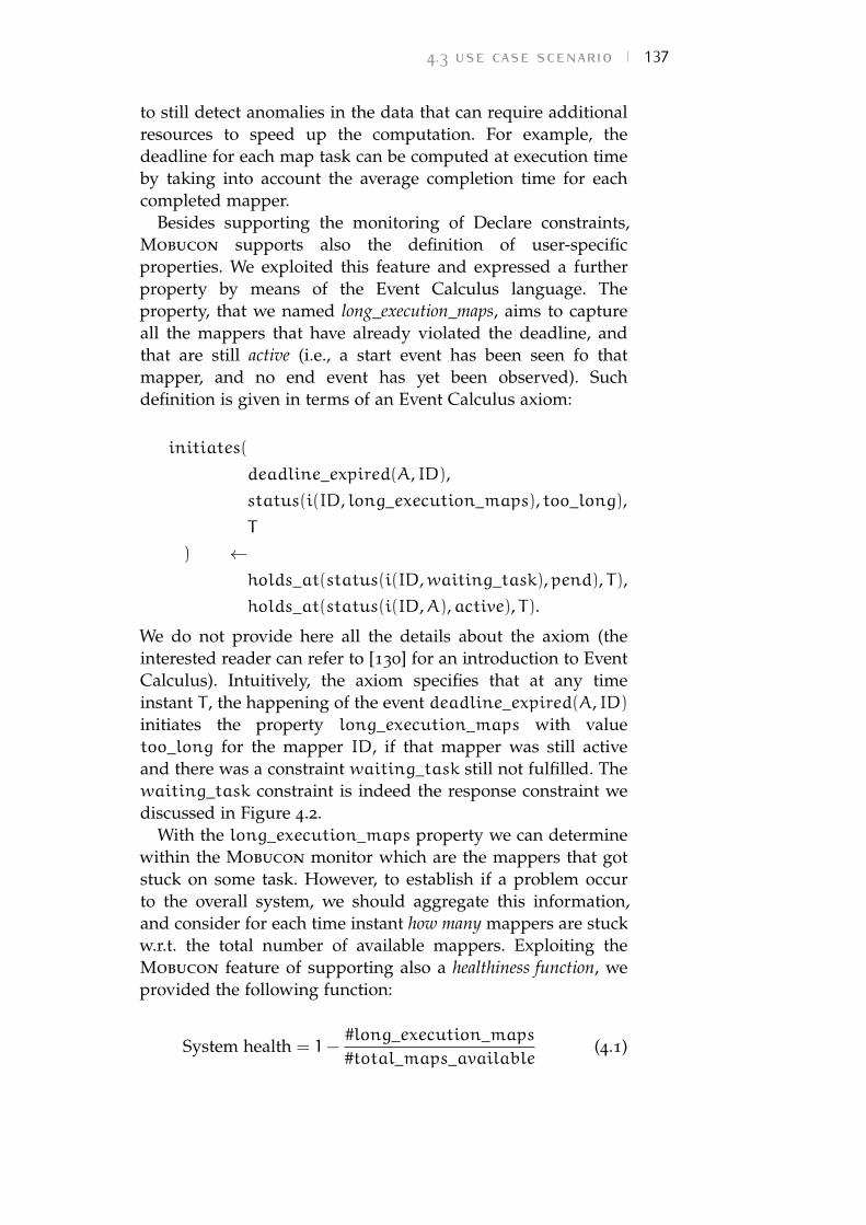
4.3 use case scenario 137
to still detect anomalies in the data that can require additionalresources to speed up the computation. For example, thedeadline for each map task can be computed at execution timeby taking into account the average completion time for eachcompleted mapper.
Besides supporting the monitoring of Declare constraints,Mobucon supports also the definition of user-specificproperties. We exploited this feature and expressed a furtherproperty by means of the Event Calculus language. Theproperty, that we named long_execution_maps, aims to captureall the mappers that have already violated the deadline, andthat are still active (i.e., a start event has been seen fo thatmapper, and no end event has yet been observed). Suchdefinition is given in terms of an Event Calculus axiom:
initiates(
deadline_expired(A, ID),status(i(ID, long_execution_maps), too_long),T
) ←holds_at(status(i(ID,waiting_task),pend), T),holds_at(status(i(ID,A),active), T).
We do not provide here all the details about the axiom (theinterested reader can refer to [130] for an introduction to EventCalculus). Intuitively, the axiom specifies that at any timeinstant T , the happening of the event deadline_expired(A, ID)
initiates the property long_execution_maps with valuetoo_long for the mapper ID, if that mapper was still activeand there was a constraint waiting_task still not fulfilled. Thewaiting_task constraint is indeed the response constraint wediscussed in Figure 4.2.
With the long_execution_maps property we can determinewithin the Mobucon monitor which are the mappers that gotstuck on some task. However, to establish if a problem occurto the overall system, we should aggregate this information,and consider for each time instant how many mappers are stuckw.r.t. the total number of available mappers. Exploiting theMobucon feature of supporting also a healthiness function, weprovided the following function:
System health = 1−#long_execution_maps#total_maps_available
(4.1)
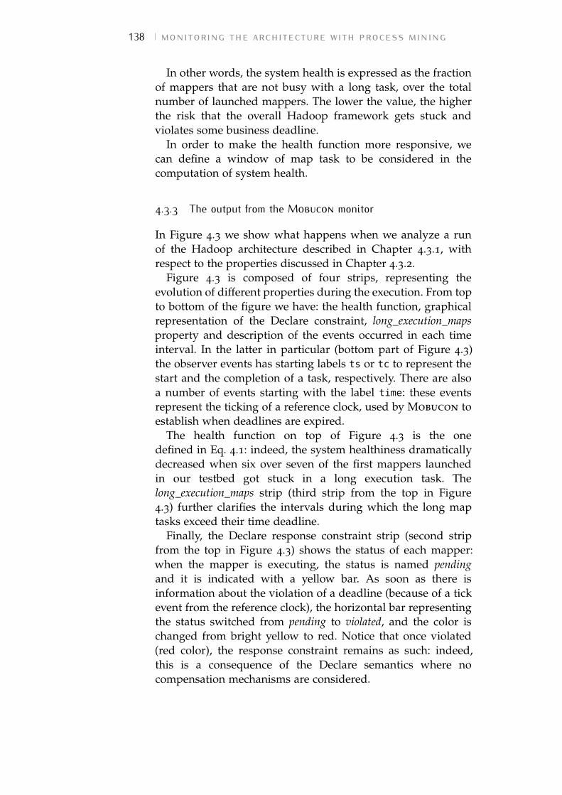
138 monitoring the architecture with process mining
In other words, the system health is expressed as the fractionof mappers that are not busy with a long task, over the totalnumber of launched mappers. The lower the value, the higherthe risk that the overall Hadoop framework gets stuck andviolates some business deadline.
In order to make the health function more responsive, wecan define a window of map task to be considered in thecomputation of system health.
4.3.3 The output from the Mobucon monitor
In Figure 4.3 we show what happens when we analyze a runof the Hadoop architecture described in Chapter 4.3.1, withrespect to the properties discussed in Chapter 4.3.2.
Figure 4.3 is composed of four strips, representing theevolution of different properties during the execution. From topto bottom of the figure we have: the health function, graphicalrepresentation of the Declare constraint, long_execution_mapsproperty and description of the events occurred in each timeinterval. In the latter in particular (bottom part of Figure 4.3)the observer events has starting labels ts or tc to represent thestart and the completion of a task, respectively. There are alsoa number of events starting with the label time: these eventsrepresent the ticking of a reference clock, used by Mobucon toestablish when deadlines are expired.
The health function on top of Figure 4.3 is the onedefined in Eq. 4.1: indeed, the system healthiness dramaticallydecreased when six over seven of the first mappers launchedin our testbed got stuck in a long execution task. Thelong_execution_maps strip (third strip from the top in Figure4.3) further clarifies the intervals during which the long maptasks exceed their time deadline.
Finally, the Declare response constraint strip (second stripfrom the top in Figure 4.3) shows the status of each mapper:when the mapper is executing, the status is named pendingand it is indicated with a yellow bar. As soon as there isinformation about the violation of a deadline (because of a tickevent from the reference clock), the horizontal bar representingthe status switched from pending to violated, and the color ischanged from bright yellow to red. Notice that once violated(red color), the response constraint remains as such: indeed,this is a consequence of the Declare semantics where nocompensation mechanisms are considered.
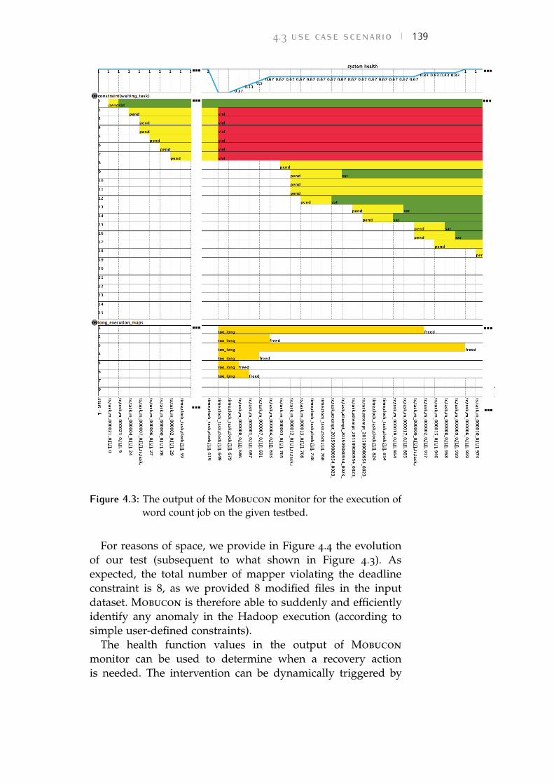
4.3 use case scenario 139
Figure 4.3: The output of the Mobucon monitor for the execution ofword count job on the given testbed.
For reasons of space, we provide in Figure 4.4 the evolutionof our test (subsequent to what shown in Figure 4.3). Asexpected, the total number of mapper violating the deadlineconstraint is 8, as we provided 8 modified files in the inputdataset. Mobucon is therefore able to suddenly and efficientlyidentify any anomaly in the Hadoop execution (according tosimple user-defined constraints).
The health function values in the output of Mobucon
monitor can be used to determine when a recovery actionis needed. The intervention can be dynamically triggered by
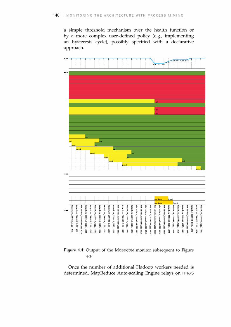
140 monitoring the architecture with process mining
a simple threshold mechanism over the health function orby a more complex user-defined policy (e.g., implementingan hysteresis cycle), possibly specified with a declarativeapproach.
Figure 4.4: Output of the Mobucon monitor subsequent to Figure4.3.
Once the number of additional Hadoop workers needed isdetermined, MapReduce Auto-scaling Engine relays on HyIaaS
4.4 conclusions and future work 141
for the provisioning of VMs over a single public cloud orfederated hybrid environment.
4.4 conclusions and future workIn this chapter, we presented a framework architecture thatencapsulates an application level platform for data-processing.The system lends the MapReduce infrastructure the ability toautonomously check the execution, detecting bottlenecks andconstraint violations through Business Process Managementtechniques with a best effort approach.
Focusing on activities and constraints, the use of Declarelanguage has shown significant advantages in the monitoringsystem implementation and customization.
Although this work represents just a first step towards anauto-scaling engine for MapReduce, its declarative approach tothe monitoring issue shows promising results, both regardingthe reactivity to critical conditions and the simplification inmonitoring constraint definition.
For the future, we plan to employ the defined frameworkarchitecture to test various diagnosis and recovery policies andverify the efficacy of the overall auto-scaling engine in a widerscenario (i.e., with a higher number of MapReduce workersinvolved).
Finally, particular attention must be given to the hybridcloud scenario, where the HyIaaS component is employedto transparently perform VM provisioning either on anon-premise internal or an off-premise public cloud. In case of ahybrid deploy, several additional constraints can be taken intoaccount by expressing them through declarative constraints.For example, the case of the limited inter-cloud bandwidthslowing-down the computation can be easily detected bythe declarative monitoring engine that processes Hadooplogs thus on-line identifying the incidence of non-data-localcomputations.
While the monitoring policy implemented in this work israther simple and can calculated on-the-fly during MapReducejob execution, we expect the introduction of additionalconstraints to further increase the computational complexityof the resulting monitoring and recovery policies. Therefore,an accurate study of the performance of our approach will benecessary. Nevertheless, we believe that a declarative approach

142 monitoring the architecture with process mining
to the problem can contribute to significantly simplify thethe work of the system administrator as he implements themonitoring policy by simply enunciating the set of propertiesthe system must be compliant to.
5 C O N C L U S I O N S A N DF U T U R E D I R E C T I O N S
A lot of effort – in the academic as well as industrialresearch field – is concentrated on the autonomic managementof virtual infrastructures and further encouraged by the risingneed for enabling data-intensive applications leveraging amultiple-cloud environment.
5.1 summaryIn this dissertation, we have presented our work on policiesand mechanisms to enable the autonomic management ofvirtual infrastructures in cloud environments.
We initially focused on the single-cloud scenario, werethe need for VM management is mostly determined bythe fulfillment of two contrasting targets: restrain powerwaste and avoid performance degradation due to limitedphysical resource contention. After introducing the mainworks conducted in this filed, we presented our contributionto autonomic VM management: a decentralized solution forcloud virtual infrastructure, in which the physical hosts ofthe datacenter are able to self-organize and reach a globalVM reallocation plan, according to a specific predefinedgoal. The implemented policies show good performance forvarious data centers dimensions in terms of both number ofmigrations requested and number of messages exchanged inorder to converge to a common reallocation plan. Nevertheless,although very promising to improve the scalability of a singlecloud scenario, decentralized solutions have shown substantialshortcomings from the performance point of view whencompared to centralized solutions.
This finding has also influenced our latter researchwhen dealing with autonomic management in the hybridcloud scenario. Aiming to combine the virtual infrastructureadministration strategies of both on- and off-premise cloud,the developed framework architecture presented in Chapter 3.3
143
144 conclusions and future directions
has indeed a centralized nature. In fact, as regards the policyimplementation, the proposed architecture partially distributeon the cloud compute nodes the monitoring and managementlogic duties (by arranging the correspondent components oneach physical node). Nevertheless, we introduced a centralcoordination of the migration/spawning decisions, thus toprevent inconsistent evolutions of the strategy.
In this work, we also focused on the topic of data-intensiveapplications and, in particular, on the strategies to enableMapReduce execution over the hybrid cloud. The challengesof this field are due to the complexity of both the applicativescenario and the infrastructure level specificities.
For this reason, we focused on different policies aiming toautonomously manage the virtual clusters avoiding furthercomplexity. A declarative approach in particular, has beenemployed in Chapter 4 in order to simplify the monitoringconstraint definition for a MapReduce application running ona virtual infrastructure. The adopted approach has showninteresting and promising results.
5.2 conclusionsThe autonomic management of virtual resources in clouddatacenters is intrinsically complicated by the scale of theinfrastructure, the variety of resources that need to bemonitored and the contrasting goals (load balancing versusconsolidation) to be pursued.
Decentralized solutions can be a good way to face thiscomplexity by partitioning the management duties amongdifferent machines of the datacenter. Each node executessimple operations – according to a predefined policy –resulting in a complex emergent self-managing behavior of theinfrastructure as a whole. Albeit the scalability and reliabilityof the system is improved when compered to centralizedmanagement architectures, our research has highlightedinevitable performance drawbacks in distributed solutions.
For this reason, when the scenario is further complicatedby the presence of multiple interoperable clouds (such as ina hybrid cloud scenario), a combination of both centralizedand distributed coordination techniques can represent a goodchoice to manage the complexity without compromising theperformance.
5.3 future research directions 145
Nevertheless, data-intensive tests conducted on hybridinfrastructures have highlighted the necessity to enrichthe management system with application level monitoringinformation to a priori evaluate the performance improvementsderived from VM migration/spawning decisions. The intricaciesof taking into account both low- and high-level monitoringinformations make essential the introduction of noveltechniques – such as those borrowed from Business ProcessManagement (BPM) area – to simplify the elicitation of theconstraints to be runtime fulfilled by the system. Our researchhas shown that declarative methods can bring substantialimprovements in this regard.
5.3 future research directionsIn this dissertation, we have explored several importantresearch aspects of the autonomic infrastructure managementproblem but we have also identified many still open researchquestions worth pursuing. In this final chapter, we summarizethe primary directions that, in our opinion, should drive futureresearch efforts:
• Improve cloud interoperability. The cooperation betweenmultiple clouds in order to offer an integrated resourceprovisioning service raises many more challenges thancloud computing. Beyond the challenge of enabling thecooperation through the adoption of common interfaces,other issues need to be faced. For example, thepublication, discovery and selection of the services andresources offered by cooperating clouds is complicatedby the scale of the environment, as well as the definitionof a common set of SLAs that can be guaranteed tothe customers by different providers. Another importantchallenge in this field is enabling inter-cloud migration,as it is complicated by the absence of a shared storage andthe necessity to transfer memory, status and storage ofthe VMs trough a high latency medium. Furthermore, themonitoring systems of different clouds must implementstrategies to cooperate in order to enable the autonomicmanagement of the resulting whole set of resources.• Enhance decentralized techniques for management. Although
the performance of these strategies are still limited
146 conclusions and future directions
when compared to those of centralized architectures, webelieve that the benefits in terms of system scalabilitythat a decentralized approach can bring to the autonomicmanagement of a multiple clouds environment, justifyfurther research in this field – especially if we considerthe vision of an Inter-cloud environment, where eachuser can leverage and offer resources to a common“cloud of clouds”.• Combine different monitoring/recovery approaches. An inter-
esting research direction in the field of federated/hybridcloud computing is the definition of novel strategies formonitoring in order to combine the current status of theinfrastructure (physical and virtual resource utilization)with information about the application level computationtaking place (e.g., execution logs, applicative monitors,etc.). These challenge can be faced leveraging both classicoptimization algorithms and declarative approaches.Substantially simplifying the definition of the expectedsystem behavior (instead of focusing of all the possibleerror/undesired situations), we believe that declarativeapproaches are particularly promising to model both themonitoring and recovery of multiple-cloud managementsystems.
B I B L I O G R A P H Y
[1] A. N. Toosi, R. N. Calheiros, and R. Buyya, “Interconnectedcloud computing environments: Challenges, taxonomy,and survey,” ACM Comput. Surv., vol. 47, pp. 7:1–7:47, May2014.
[2] K. Pepple, Deploying OpenStack creating open source clouds.O’Reilly, 2013.
[3] S. Rajan and A. Jairath, “Cloud computing: The fifthgeneration of computing,” in International Conferenceon Communication Systems and Network Technologies (CSNT)(IEEE, ed.), vol. 15 - n 4, pp. 665–667, 2011.
[4] M. Armbrust, A. Fox, R. Griffith, A. D. Joseph, R. H. Katz,A. Konwinski, G. Lee, D. A. Patterson, A. Rabkin, andM. Zaharia, “Above the clouds: A berkeley view of cloudcomputing,” tech. rep., Berkeley, 2009.
[5] OpenStack community, “Openstack: Opensource cloudcomputing software.” https://www.openstack.org/. WebPage, last visited in Oct. 2015.
[6] Amazon.com, Inc., “Amazon elastic compute cloud (ec2).”http://aws.amazon.com/ec2. Web Page, last visited inOct. 2015.
[7] Aptana, Inc., “Aptana cloud.” http://aptana.com/cloud.Web Page, last visited in Oct. 2015.
[8] Manjrasoft Pty Ltd. , “Aneka cloud.” http://www.
manjrasoft.com/manjrasoft_company.html, 2015. WebPage, last visited in Dec. 2015.
[9] X. Fan, W.-D. Weber, and L. A. Barroso, “Powerprovisioning for a warehouse-sized computer,” in The34th ACM International Symposium on Computer Architecture,pp. 13–23, ACM New York, 2007.
[10] B. Rochwerger, D. Breitgand, E. Levy, A. Galis, K. Nagin,I. Llorente, R. Montero, Y. Wolfsthal, E. Elmroth, J. Caceres,M. Ben-Yehuda, W. Emmerich, and F. Galan, “The
147
148 bibliography
reservoir model and architecture for open federatedcloud computing,” IBM Journal of Research and Development,vol. 53, pp. 4:1–4:11, July 2009.
[11] D. Petcu, C. Craciun, M. Neagul, S. Panica, B. Di Martino,S. Venticinque, M. Rak, and R. Aversa, “Architecturing asky computing platform,” in Towards a Service-Based Internet.ServiceWave 2010 Workshops (M. Cezon and Y. Wolfsthal,eds.), vol. 6569 of Lecture Notes in Computer Science, pp. 1–13,Springer Berlin Heidelberg, 2011.
[12] Jung, “Mistral: Dynamically managing power, perfor-mance, and adaptation cost in cloud infrastructures,”in International Conference on Distributed Computing Systems(IEEE, ed.), pp. 62–73, June 2010.
[13] H. C. Lim, S. Babu, and J. S. Chase, “Automatedcontrol in cloud computing challeges and opportunities,”in ACDC ’09, Proceedings of the 1st workshop on Automatedcontrol for datacenters and clouds, pp. 13–18, ACM New York,2009.
[14] E. Kalyvianaki, “Self-adaptive and self-configured cpuresource provisioning for virtualized servers using kalmanfilters,” in ICAC ’09 Proceedings of the 6th international con-ference on Autonomic computing (ACM, ed.), pp. 117–126,2009.
[15] R. Jansen, “Energy efficient virtual machine allocationin the cloud,” in Green Computing Conference and Workshops(IGCC), 2011 International, pp. 1–8, IEEE, July 2011.
[16] A. J. Younge, “Efficient resource management for cloudcomputing environments,” in Green Computing Conference,2010 International, pp. 357–364, IEEE, August 2010.
[17] A. Beloglazov and R. Buyya, “Optimal online determin-istic algorithms and adaptive heuristics for energy andperformance efficient dynamic consolidation of virtual ma-chines in cloud data centers,” Concurrency and Computation:Practice and Experience, vol. 24, pp. 1397–1420, September2012.
[18] J. Levine and F. Ducatelle, “Ant colony optimisation andlocal search for bin packing and cutting stock problems,”Journal of the Operational Research Society, pp. 1–16, 2003.
bibliography 149
[19] S. Zaman and D. Grosu, “Combinatorial auction-based allocation of virtual machine instances in clouds,” in2010 IEEE Second International Conference on Cloud ComputingTechnology and Science (CloudCom) (IEEE, ed.), pp. 127–134,December 2010.
[20] A. Marinos and G. Briscoe, “Community cloud com-puting,” in First International Conference, CloudCom 2009.Proceedings, pp. 472–484, Springer Berlin Heidelberg, 2009.
[21] C. Giovanoli and S. G. Grivas, “Community clouds acentralized approach,” in CLOUD COMPUTING 2013, TheFourth International Conference on Cloud Computing, GRIDs,and Virtualization (IARIA, ed.), pp. 43–48, 2013.
[22] K. Chard, S. Caton, O. Rana, and K. Bubendorfer, “Socialcloud: Cloud computing in social networks,” in CloudComputing (CLOUD), 2010 IEEE 3rd International Conferenceon, July 2010.
[23] R. Giordanelli, C. Mastroianni, and M. Meo, “Bio-inspired p2p systems: The case of multidimensionaloverlay,” ACM Transactions on Autonomous and Adaptive Sys-tems (TAAS), vol. 7, p. Article No. 35, December 2012.
[24] S. Balasubramaniam, K. Barrett, W. Donnelly, and S. V. D.Meer, “Bio-inspired policy based management (biopbm)for autonomic communications systems,” in 7th IEEEInternational workshop on Policies for Distributed Systems andNetworks (IEEE, ed.), pp. 3–12, June 2006.
[25] M. Marzolla, O. Babaoglu, and F. Panzieri, “Serverconsolidation in clouds through gossiping,” TechnicalReport UBLCS-2011-01, 2011.
[26] A. Vichos, Agent-based management of Virtual Machines forCloud infrastructure. PhD thesis, School of Informatics,University of Edinburgh, 2011.
[27] X. Meng, V. Pappas, and L. Zhang, “Improving thescalability of data center networks with traffic-awarevirtual machine placement,” in INFOCOM, 2010 ProceedingsIEEE, March 2010.
[28] M. Sindelar, R. K. Sitaraman, and P. Shenoy, “Sharing-aware algorithms for virtual machine colocation,” in
150 bibliography
Proceedings of the twenty-third annual ACM symposium on Par-allelism in algorithms and architectures, pp. 367–378, 2011.
[29] R. Lent, “Evaluating the performance and power consump-tion of systems with virtual machines,” in Cloud ComputingTechnology and Science (CloudCom), 2011 IEEE Third Interna-tional Conference on, pp. 778 – 783, 2011.
[30] A. Kansal, F. Zhao, J. Liu, N. Kothari, and A. Bhattacharya,“Virtual machine power metering and provisioning,” inACM Symposium on Cloud Computing (SOCC), June 2010.
[31] S. Parekh, N. Gandhi, J. Hellerstein, D. Tilbury, T. Jayram,and J. Bigus, “Using control theory to achieve service levelobjectives in performance management. in proc. of im,2002.,” in In Proc. of IM, 2002.
[32] G. Soundararajan, C. Amza, and A. Goel, “Databasereplication policies for dynamic content applications,” inProc. of EuroSys, 2006.
[33] B. Urgaonkar, P. Shenoy, A. Chandra, and P. Goyal,“Dynamic provisioning of multi-tier internet applications,”in Proc. of ICAC, 2005.
[34] Joyent, Inc., “Joyent triton elastic container service.”http://www.joyent.com. Web Page, last visited inOct. 2015.
[35] P. Padala, K. G. Shin, X. Zhu, M. Uysal, Z. Wang,S. Singhal, A. Merchant, and K. Salem, “Adaptivecontrol of virtualized resources in utility computingenvironments,” in Proc. of EuroSys, 2007.
[36] A. S. Foundation, “Apache tomcat.” http://tomcat.
apache.org. Web Page, last visited in Oct. 2015.
[37] D. Loreti, “Infrastruttura di supporto ad un’architetturacloud,” Master’s thesis, University of Bologna, 2009.
[38] C. Hyser, B. Mckee, R. Gardner, and B. J. Watson,“Autonomic virtual machine placement in the datacenter,”,” tech. rep., HP Laboratories, December 2007.
[39] A. Beloglazov, J. Abawajy, and R. Buyya, “Energy-awareresource allocation heuristics for efficient managementof data centers for cloud computing,” Future GenerationComputer Systems, vol. 28, pp. 755–768, May 2012.
bibliography 151
[40] M. Yue, A simple proof of the inequality FFD (L)<11/9 OPT(L)+ 1,for all l for the FFD bin-packing algorithm,. Acta Mathe-maticae Applicatae Sinica, 1991.
[41] A. Verma, G. Dasgupta, T. Nayak, P. De, and R. Kothari,“Server workload analysis for power minimization us-ing consolidation,” Proceedings of the 2009 USENIX AnnualTechnical Conference, pp. 28–28, 2009.
[42] H. Abdi, Multiple correlation coefficient, pp. 648–651. Sage,Thousand Oaks, CA, 2007.
[43] M. Jelasity, A. Montresor, and O. Babaoglu, “Gossip-basedaggregation in large dinamic networks,” ACM Transactionon Computer Systems, vol. 23, pp. 219–252, August 2005.
[44] M. Tighe, G. Keller, M. Bauer, and H. Lutfiyya, “Adistributed approach to dynamic vm management,” in Net-work and Service Management (CNSM), 2013 9th InternationalConference on, pp. 166–170, October 2013.
[45] D. Loreti and A. Ciampolini, “A decentralized approachfor virtual infrastructure management in cloud datacen-ters,” International Journal On Advances in Intelligent Systems,vol. 7, no. 3-4, pp. 507–518, 2014.
[46] D. Loreti and A. Ciampolini, “Policy for distributedself-organizing infrastructure management in cloud data-centers,” in Proceedings of The Tenth International Conferenceon Autonomic and Autonomous Systems, IARIA, 2014.
[47] D. Loreti and A. Ciampolini, “Green-dam: a power-aware self-organizing approach for cloud infrastructuremanagement,” tech. rep., University of Bologna, 2013.
[48] D. Loreti and A. Ciampolini, “A distributed self-balancing policy for virtual machine management in clouddatacenters,” in High Performance Computing Simulation(HPCS), 2014 International Conference on, pp. 391–398, July2014.
[49] D. Loreti and A. Ciampolini, “A decentralized approachfor virtual infrastructure management in cloud datacen-ters,” International Journal On Advances in Intelligent Systems,vol. 7, pp. 507–518, December 2014.
[50] S. Martello and P. Toth, Knapsack Problems. Wiley, 1990.
152 bibliography
[51] D. Loreti and A. Ciampolini, “Policy for distributedself-organizing infrastructure management in cloud data-centers,” in ICAS 2014, The Tenth International Conference onAutonomic and Autonomous Systems, pp. 37–43, April 2014.
[52] D. Loreti, “Distributed autonomic manager simulator- damsim.” https://bitbucket.org/dloreti/cooperating.
cloud.man, 2013. Web Page, last visited in Oct. 2015.
[53] A. Greenberg, J. R. Hamilton, N. Jain, S. Kandula, andC. Kim, “Vl2: a scalable and flexible data center network,”in SIGCOMM ’09 Proceedings of the ACM SIGCOMM 2009conference on Data communication (ACM, ed.), pp. 51–62,October 2009.
[54] R. N. Calheiros, A. N. Toosi, C. Vecchiola, andR. Buyya, “A coordinator for scaling elastic applicationsacross multiple clouds,” Future Generation Computer Systems,vol. 28, no. 8, pp. 1350 – 1362, 2012. Including Specialsections SS: Trusting Software Behavior and SS: Economicsof Computing Services.
[55] T. Aoyama and H. Sakai, “Inter-cloud computing,”Business and Information Systems Engineering, vol. 3, no. 3,pp. 173–177, 2011.
[56] R. Buyya, R. Ranjan, and R. Calheiros, “Intercloud: Utility-oriented federation of cloud computing environmentsfor scaling of application services,” in Algorithms andArchitectures for Parallel Processing (C.-H. Hsu, L. Yang,J. Park, and S.-S. Yeo, eds.), vol. 6081 of Lecture Notes inComputer Science, pp. 13–31, Springer Berlin Heidelberg,2010.
[57] M. Chen, S. Mao, and Y. Liu, “Big data: A survey,”Mobile Networks and Applications, vol. Volume 19, no. 2,pp. 171–209, 2014.
[58] J. Dean and S. Ghemawat, “Mapreduce: Simplified dataprocessing on large clusters,” Commun. ACM, vol. 51,pp. 107–113, Jan. 2008.
[59] Apache Software Foundation, “Hadoop mapreduce.”http://hadoop.apache.org/. Web Page, last visited inDec. 2013.
bibliography 153
[60] D. Bernstein, E. Ludvigson, K. Sankar, S. Diamond, andM. Morrow, “Blueprint for the intercloud - protocolsand formats for cloud computing interoperability,”in Internet and Web Applications and Services, 2009. ICIW ’09.Fourth International Conference on, pp. 328–336, May 2009.
[61] T. Kurze, M. Klemsy, D. Bermbachy, A. Lenkz, S. Taiy,and M. Kunze., “Cloud federation,” in Proceedings of the2nd International Conference on Cloud Computing, GRIDs, andVirtualization, pp. 32–38, 2011.
[62] D. Chen and G. Doumeingts, “European initiatives todevelop interoperability of enterprise applications—basicconcepts, framework and roadmap,” Annual Reviews inControl, vol. 27, no. 2, pp. 153 – 162, 2003.
[63] M. Armbrust, A. Fox, R. Griffith, A. D. Joseph, R. Katz,A. Konwinski, G. Lee, D. Patterson, A. Rabkin, I. Stoica,and M. Zaharia, “A view of cloud computing,” Commun.ACM, vol. 53, pp. 50–58, Apr. 2010.
[64] Google Inc., “App engine - google cloud platform.”https://developers.google.com/appengine/. Web Page,last visited in Dec. 2015.
[65] A. J. Ferrer, F. Hernandez, J. Tordsson, E. Elmroth,A. Ali-Eldin, C. Zsigri, R. Sirvent, J. Guitart, R. M.Badia, K. Djemame, W. Ziegler, T. Dimitrakos, S. K. Nair,G. Kousiouris, K. Konstanteli, T. Varvarigou, B. Hudzia,A. Kipp, S. Wesner, M. Corrales, N. Forgó, T. Sharif, andC. Sheridan, “Optimis: A holistic approach to cloud serviceprovisioning,” Future Generation Computer Systems, vol. 28,no. 1, pp. 66 – 77, 2012.
[66] D. Villegas, N. Bobroff, I. Rodero, J. Delgado, Y. Liu,A. Devarakonda, L. Fong, S. M. Sadjadi, and M. Parashar,“Cloud federation in a layered service model,” Journal ofComputer and System Sciences, vol. 78, no. 5, pp. 1330 – 1344,2012. {JCSS} Special Issue: Cloud Computing 2011.
[67] Apache Software Foundation, “Apachespark.” http:
//spark.apache.org, 2015. Web Page, last visited inDec. 2015.
[68] Jaliya Ekanayake. Supported by SALSA Team atIndiana University, “Twister, iterative mapreduce.” http:
154 bibliography
//www.iterativemapreduce.org, 2015. Web Page, lastvisited in Dec. 2015.
[69] Google Inc., “Google mapreduce for ap-pengine..” https://cloud.google.com/appengine/docs/
python/dataprocessing/, 2015. Web Page, last visited inDec. 2015.
[70] H. Zhang, G. Jiang, K. Yoshihira, H. Chen, and A. Saxena,“Intelligent workload factoring for a hybrid cloudcomputing model,” in Services - I, 2009 World Conference on,pp. 701–708, July 2009.
[71] C.-H. Suen, M. Kirchberg, and B. S. Lee, “Efficient migra-tion of virtual machines between public and private cloud,”in Cloud Computing Technology and Science (CloudCom), 2011IEEE Third International Conference on, pp. 549–553, Nov2011.
[72] E. Collins, “Intersection of the cloud and big data,” CloudComputing, IEEE, vol. 1, pp. 84–85, May 2014.
[73] W.-T. Tsai, P. Zhong, J. Elston, X. Bai, and Y. Chen,“Service replication strategies with mapreduce in clouds,”in Autonomous Decentralized Systems (ISADS), 2011 10th In-ternational Symposium on, pp. 381–388, March 2011.
[74] F. Tian and K. Chen, “Towards optimal resource provision-ing for running mapreduce programs in public clouds,”in Cloud Computing (CLOUD), 2011 IEEE International Con-ference on, pp. 155–162, July 2011.
[75] T. Gunarathne, T.-L. Wu, J. Qiu, and G. Fox, “Mapreducein the clouds for science,” in Cloud Computing Technology andScience (CloudCom), 2010 IEEE Second International Conferenceon, pp. 565–572, Nov 2010.
[76] X. Zhang, L. Yang, C. Liu, and J. Chen, “A scalabletwo-phase top-down specialization approach for dataanonymization using mapreduce on cloud,” Parallel andDistributed Systems, IEEE Transactions on, vol. 25, pp. 363–373, Feb 2014.
[77] B. Nicolae, P. Riteau, and K. Keahey, “Bursting the clouddata bubble: Towards transparent storage elasticity in iaasclouds,” in Parallel and Distributed Processing Symposium,2014 IEEE 28th International, pp. 135–144, May 2014.
bibliography 155
[78] B. Nicolae, P. Riteau, and K. Keahey, “Transparentthroughput elasticity for iaas cloud storage using guest-sideblock-level caching,” in Utility and Cloud Computing (UCC),2014 IEEE/ACM 7th International Conference on, pp. 186–195,Dec 2014.
[79] K. Chen, J. Powers, S. Guo, and F. Tian, “Cresp: Towardsoptimal resource provisioning for mapreduce computingin public clouds,” Parallel and Distributed Systems, IEEETransactions on, vol. 25, pp. 1403–1412, June 2014.
[80] B. Palanisamy, A. Singh, and L. Liu, “Cost-effectiveresource provisioning for mapreduce in a cloud,”Parallel and Distributed Systems, IEEE Transactions on, vol. 26,pp. 1265–1279, May 2015.
[81] N. B. Rizvandi, J. Taheri, R. Moraveji, and A. Y.Zomaya, “A study on using uncertain time series matchingalgorithms for mapreduce applications,” Concurrencyand Computation: Practice and Experience, vol. 25, no. 12,pp. 1699–1718, 2013.
[82] A. Verma, L. Cherkasova, and R. H. Campbell, ResourceProvisioning Framework for MapReduce Jobs with PerformanceGoals, vol. 7049 of Lecture Notes in Computer Science, pp. 165–186. Springer Berlin Heidelberg, 2011.
[83] M. Cardosa, C. Wang, A. Nangia, A. Chandra, andJ. Weissman, “Exploring mapreduce efficiency with highly-distributed data,” in Proceedings of the Second InternationalWorkshop on MapReduce and Its Applications, MapReduce ’11,(New York, NY, USA), pp. 27–34, ACM, 2011.
[84] T. Bicer, D. Chiu, and G. Agrawal, “A framework fordata-intensive computing with cloud bursting,” in ClusterComputing (CLUSTER), 2011 IEEE International Conference on,pp. 169–177, Sept 2011.
[85] K. Nagin, D. Hadas, Z. Dubitzky, A. Glikson, I. Loy,B. Rochwerger, and L. Schour, “Inter-cloud mobilityof virtual machines,” in Proceedings of the 4th AnnualInternational Conference on Systems and Storage, SYSTOR ’11,(New York, NY, USA), pp. 3:1–3:12, ACM, 2011.
[86] T. Guo, U. Sharma, P. Shenoy, T. Wood, and S. Sahu,“Cost-aware cloud bursting for enterprise applications,”
156 bibliography
ACM Trans. Internet Technol., vol. 13, pp. 10:1–10:24, May2014.
[87] H. Zhang, G. Jiang, K. Yoshihira, and H. Chen, “Proactiveworkload management in hybrid cloud computing,” Net-work and Service Management, IEEE Transactions on, vol. 11,pp. 90–100, March 2014.
[88] M. Mattess, R. Calheiros, and R. Buyya, “Scalingmapreduce applications across hybrid clouds to meetsoft deadlines,” in Advanced Information Networking andApplications (AINA), 2013 IEEE 27th International Conferenceon, pp. 629–636, March 2013.
[89] S. Kailasam, P. Dhawalia, S. Balaji, G. Iyer, andJ. Dharanipragada, “Extending mapreduce across cloudswith bstream,” Cloud Computing, IEEE Transactions on, vol. 2,pp. 362–376, July 2014.
[90] B. Sharma, T. Wood, and C. Das, “Hybridmr: Ahierarchical mapreduce scheduler for hybrid data centers,”in Distributed Computing Systems (ICDCS), 2013 IEEE 33rdInternational Conference on, pp. 102–111, July 2013.
[91] A. Abouzeid, K. Bajda-Pawlikowski, D. Abadi, A. Sil-berschatz, and A. Rasin, “Hadoopdb: An architecturalhybrid of mapreduce and dbms technologies for analyticalworkloads,” Proc. VLDB Endow., vol. 2, pp. 922–933, August2009.
[92] K. Shirahata, H. Sato, and S. Matsuoka, “Hybrid maptask scheduling for gpu-based heterogeneous clusters,”in Cloud Computing Technology and Science (CloudCom), 2010IEEE Second International Conference on, pp. 733–740, Nov2010.
[93] M. M. Rafique, A. R. Butt, and D. S. Nikolopoulos,“A capabilities-aware framework for using computationalaccelerators in data-intensive computing,” J. Parallel Distrib.Comput., vol. 71, pp. 185–197, Feb. 2011.
[94] M. Rafique, B. Rose, A. Butt, and D. Nikolopoulos,“Cellmr: A framework for supporting mapreduce onasymmetric cell-based clusters,” in Parallel DistributedProcessing, 2009. IPDPS 2009. IEEE International Symposiumon, pp. 1–12, May 2009.
bibliography 157
[95] R. Van den Bossche, K. Vanmechelen, and J. Broeckhove,“Cost-optimal scheduling in hybrid iaas clouds for deadlineconstrained workloads,” in Cloud Computing (CLOUD), 2010IEEE 3rd International Conference on, pp. 228–235, July 2010.
[96] S. Imai, T. Chestna, and C. A. Varela, “Accurate resourceprediction for hybrid iaas clouds using workload-tailoredelastic compute units,” in Proceedings of the 2013 IEEE/ACM6th International Conference on Utility and Cloud Computing,UCC ’13, (Washington, DC, USA), pp. 171–178, IEEEComputer Society, 2013.
[97] D. Loreti and A. Ciampolini, “A hybrid cloudinfrastructure for big data applications,” in Proceedings of the17th International Conferences on High Performance Computingand Communications, IEEE, 2015.
[98] D. Loreti and A. Ciampolini, “Shyam: a system forautonomic management of virtual clusters in hybridclouds,” in 1st Workshop on Federated Cloud Networking(FedCloudNet), Springer, 2015.
[99] D. Loreti and A. Ciampolini, “Mapreduce over thehybrid cloud: a novel infrastructure management policy,”in Proceedings of the 8th IEEE/ACM International Conferenceon Utility and Cloud Computing, 2015.
[100] F. J. Clemente-Castellò, B. Nicolae, K. Katrinis, M. M.Rafique, R. Mayo, J. C. Fernàndez, and D. Loreti,“Enabling big data analytics in the hybrid cloud usingiterative mapreduce,” in Proceedings of the 8th IEEE/ACMInternational Conference on Utility and Cloud Computing, 2015.
[101] Eucalyptus Systems, Inc., “Eucalyptus.” https://www.
eucalyptus.com/. Web Page, last visited in Dec. 2015.
[102] Apache Software Foundation, “Cloudstack.” https:
//cloudstack.apache.org/, 2015. Web Page, last visited inDec. 2015.
[103] OpenNebula community, “Opennebula.” https://www.
opennebula.org/. Web Page, last visited in Dec. 2015.
[104] Open Grid Forum community, “Open grid forum.”https://www.ogf.org/. Web Page, last visited in Dec. 2015.
158 bibliography
[105] Open Grid Forum community, “Open cloud computinginterface.” https://www.occi-wg.org/. Web Page, lastvisited in Dec. 2015.
[106] Rackspace, Inc., “Rackspace public cloud.” https:
//developer.rackspace.com. Web Page, last visited inDec. 2015.
[107] Hewlett Packard Enterprise, “Hpe helion public cloud.”https://hpcloud.com. Web Page, last visited in Dec. 2015.
[108] J. Dean and S. Ghemawat, “Mapreduce: Simplifieddata processing on large clusters,” in Sixth symposium onoperating system design and implementation, (San Francisco,CA), December 2004.
[109] OpenStack community, “Sahara: module for data pro-cessing.” https://wiki.openstack.org/wiki/Sahara. WebPage, last visited in Oct. 2015.
[110] OpenStack community, “Ceilometer: monitoringmodule.” https://wiki.openstack.org/wiki/Ceilometer,2015. Web Page, last visited in Oct. 2015.
[111] PUMA, “Benchmarks and dataset downloads.” https://
engineering.purdue.edu/~puma/datasets.htm. Web Page,last visited in Oct. 2015.
[112] Apache Software Foundation, “Apache hadoopbalancer.” https://hadoop.apache.org/docs/r1.0.4/
commands_manual.html. Web Page, last visited in Oct. 2015.
[113] D. Loreti and A. Ciampolini, “A hybrid cloudinfrastructure fo big data applications,” in Proceedings ofIEEE International Conferences on High Performance Computingand Communications, 2015.
[114] K. Shvachko, H. Kuang, S. Radia, and R. Chansler,“The hadoop distributed file system,” in Mass StorageSystems and Technologies (MSST), 2010 IEEE 26th Symposiumon, pp. 1–10, May 2010.
[115] A. Verma, L. Cherkasova, and R. H. Campbell, “Aria:Automatic resource inference and allocation for mapreduceenvironments,” in Proceedings of the 8th ACM InternationalConference on Autonomic Computing, ICAC ’11, (New York,NY, USA), pp. 235–244, ACM, 2011.
bibliography 159
[116] H.-H. Bock, “Clustering methods: A history of k-meansalgorithms,” in Selected Contributions in Data Analysis andClassification, Springer Berlin Heidelberg, 2007.
[117] W. Zhao, H. Ma, and Q. He, “Parallel k-meansclustering based on mapreduce,” in Proceedings of the 1stInternational Conference on Cloud Computing, CloudCom ’09,(Berlin, Heidelberg), pp. 674–679, Springer-Verlag, 2009.
[118] W. V. D. Aalst, A. Adriansyah, A. K. A. de Medeiros, andF. Arcieri, “Process mining manifesto,” in Business ProcessManagement Workshops, Springer Berlin Heidelberg, 2012.
[119] Amazon Inc., “Amazon cloud watch: Amazoncloud monitor system..” https://aws.amazon.com/it/
cloudwatch/, 2015. Web Page, last visited in Oct. 2015.
[120] W. van der Aalst, A. ter Hofstede, and M. Weske,“Business process management: A survey,” in BusinessProcess Management (W. van der Aalst and M. Weske, eds.),vol. 2678 of Lecture Notes in Computer Science, pp. 1–12,Springer Berlin Heidelberg, 2003.
[121] M. Shanahan, “The event calculus explained,” in ArtificialIntelligence Today (M. Wooldridge and M. Veloso, eds.),vol. 1600 of Lecture Notes in Computer Science, pp. 409–430,Springer Berlin Heidelberg, 1999.
[122] M. Montali, F. M. Maggi, F. Chesani, P. Mello, andW. M. P. van der Aalst, “Monitoring business constraintswith the event calculus,” ACM TIST, vol. 5, no. 1, p. 17,2013.
[123] M. Pesic and W. M. P. van der Aalst, “A DeclarativeApproach for Flexible Business Processes Management,” inBusiness Process Management Workshops, LNCS, SPRINGER,2006.
[124] D. Loreti, A. Ciampolini, F. Chesani, and P. Mello,“Process mining monitoring for map reduce applications inthe cloud,” in Submitted to the 6th International Conference onCloud Computing and Services Science, 2016.
[125] G. Spanoudakis and K. Mahbub, “Non-intrusivemonitoring of service-based systems,” International Journalof Cooperative Information Systems, vol. 15, no. 03, pp. 325–358, 2006.
160 bibliography
[126] A. Farrel, M. Sergot, M. Sallè, and C. Bartolini, “Usingthe event calculus for tracking the normative stateof contracts,” International Journal of Cooperative InformationSystems, vol. 14, no. 02n03, pp. 99–129, 2005.
[127] D. Giannakopoulou and K. Havelund, “Automata-basedverification of temporal properties on running programs,”in Automated Software Engineering, 2001. (ASE 2001). Proceed-ings. 16th Annual International Conference on, pp. 412–416,Nov 2001.
[128] A. Bauer, M. Leucker, and C. Schallhart, “Runtimeverification for ltl and tltl,” ACM Trans. Softw. Eng.Methodol., vol. 20, pp. 14:1–14:64, Sept. 2011.
[129] M. Montali, F. Chesani, P. Mello, and F. M. Maggi,“Towards data-aware constraints in declare,” in Proceedingsof the 28th Annual ACM Symposium on Applied Computing,SAC ’13, Coimbra, Portugal, March 18-22, 2013, pp. 1391–1396, 2013.
[130] R. A. Kowalski and M. J. Sergot, “A Logic-BasedCalculus of Events,” New Generation Computing, 1986.
[131] S. Bragaglia, F. Chesani, P. Mello, M. Montali, andP. Torroni, “Reactive event calculus for monitoring globalcomputing applications,” in Logic Programs, Norms andAction, Springer, 2012.
A C K N O W L E D G E M E N T S
I would like to thank Prof. Anna Ciampolini for helping mewith competence and patience during every step of my Ph.D.studies. Her support and understanding went far beyond therole of a supervisor. Sincere thanks goes to Prof. FedericoChesani, Prof. Antonio Corradi and Prof. Paola Mello for theirprecious advices and support during these years. I also wantto thank Dr. Pól Mac Aonghusa and Dr. Konstantinos Katrinisfor giving me the chance to work with them at the IBM DublinResearch Lab; and the reviewers of this thesis, Prof. RajkumarBuyya and Dr. Mustafa Rafique for their many suggestionsthat helped to improve the quality of this work.
Thanks to all the LIA guys – Raffaele, Federico, Ambra,Allegra, Thomas, Alessio, Luca, Andrea, Marco and Roberta– for respectfully sharing office, work and ultimately – giventhe number of hours we spend together – life. A specialacknowledgment goes to all the ex-LIA for the memorablelunch discussions: Carlo, Giuseppe, Fede, Andrea, and Stefano.I still laugh by myself when I think back to some jokes. Yourcynicism, kindness, bitterness and friendship made my firstyears of Ph.D. studies unmatchable.
I also want to thank my “preo” friends spread around theworld: Gigi, Prandi, Bussi and Wero, who shared with memany absolutely silly yet incredibly important moments. Icannot forget to be grateful to the friends who are with mesince unmemorable times – Piera and Garde – for always beena save shore to me, for the wonderful years: those gone by andthose still to come. I don’t know how I would do without you.Also thanks to the friends that arrived in the last few yearsand, nevertheless, contributed to make the journey preciouslybright – the Fabulous Girls: Briga, Mary, Bea, Simo, Chiara,Elena, Marika and Tina.
161

162 acknowledgements
Finally, the most important acknowledgements are formy family, present and future. My parents and my sisterfor always being how a family should be: understanding,supportive, messy and present whenever I need them. Yourpride for each goal I achieve is pure strength to me. Alberto,my life and my future, for supporting me when the choice ofPh.D. studies was still a dangerous and confused dream: “itsounds reasonable but not yet reasoned, let’s focus”. Thankyou for encouraging me when I was about to give up, forturning every obstacle into a joke and, of course, for yourpriceless love.

fin.
![Multi Autonomic Management for Optimizing Energy ......sumption in Cloud Infrastructures. Software Engineering [cs.SE]. Université de Nantes, 2013. English. NNT: ED 503-186 . tel-00853575](https://img.pdfslide.us/doc/110x75/608c9b1e3929737f3c202ad9/multi-autonomic-management-for-optimizing-energy-sumption-in-cloud-infrastructures.jpg)