Embed Size (px)
Citation preview
Automotive motor drives system solutions 2019
www.infineon.com
Automotive motor drives
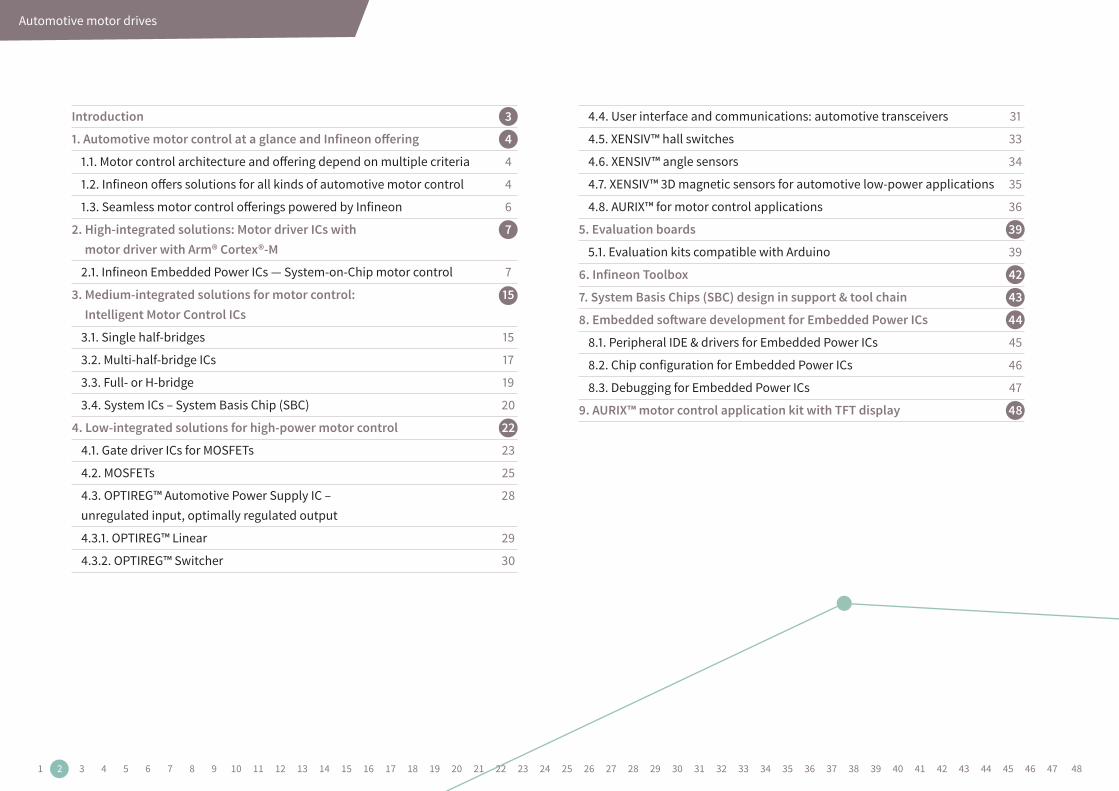
Introduction 3
1. Automotive motor control at a glance and Infineon offering 4
1.1. Motor control architecture and offering depend on multiple criteria 4
1.2. Infineon offers solutions for all kinds of automotive motor control 4
1.3. Seamless motor control offerings powered by Infineon 6
2. High-integrated solutions: Motor driver ICs with 7 motor driver with Arm® Cortex®-M
2.1. Infineon Embedded Power ICs — System-on-Chip motor control 7
3. Medium-integrated solutions for motor control: 15 Intelligent Motor Control ICs
3.1. Single half-bridges 15
3.2. Multi-half-bridge ICs 17
3.3. Full- or H-bridge 19
3.4. System ICs – System Basis Chip (SBC) 20
4. Low-integrated solutions for high-power motor control 22
4.1. Gate driver ICs for MOSFETs 23
4.2. MOSFETs 25
4.3. OPTIREG™ Automotive Power Supply IC – 28 unregulated input, optimally regulated output
4.3.1. OPTIREG™ Linear 29
4.3.2. OPTIREG™ Switcher 30
4.4. User interface and communications: automotive transceivers 31
4.5. XENSIV™ hall switches 33
4.6. XENSIV™ angle sensors 34
4.7. XENSIV™ 3D magnetic sensors for automotive low-power applications 35
4.8. AURIX™ for motor control applications 36
5. Evaluation boards 39
5.1. Evaluation kits compatible with Arduino 39
6. Infineon Toolbox 42
7. System Basis Chips (SBC) design in support & tool chain 43
8. Embedded software development for Embedded Power ICs 44
8.1. Peripheral IDE & drivers for Embedded Power ICs 45
8.2. Chip configuration for Embedded Power ICs 46
8.3. Debugging for Embedded Power ICs 47
9. AURIX™ motor control application kit with TFT display 48
1 2 3 4 5 6 7 8 9 10 11 12 13 14 15 16 17 18 19 20 21 22 23 24 25 26 27 28 29 30 31 32 33 34 35 36 37 38 39 40 41 42 43 44 45 46 47 48

Automotive motor drives
IntroductionNowadays, the number of electrical motors in cars is growing steadily. In the last years, the unit CAGR (Compound Annual Growth Rate) has always been in the range between 5 and 6 percent.
› In average around 35 motors distributed in an automobile
› About 70 motors present in premium cars
› By 2022, 4.2 billion electrical motors are expected to be built only into cars
Over a long period, mechanical solutions in the automotive industry were state of the art for oil pumps, water pumps, fuel pumps and hydraulic pumps. These days, the trend goes to the replacement of mechanical solutions by electrical motors, due to factors such:
› CO2 reduction, which has become a very high priority in the field of transportation, these mechanical pumps were gradually replaced by smart, electrically controlled motors. Instead of continuously using energy from a combustion engine, the electric motors can be switched and speed-controlled on demand.
› Advanced safety features such as crash avoidance, driving assistants and autonomous driving in the future also drive the electrical motor market forward.
› Increasing number of in-cabin comfort functionalities in mid-range cars and premium equipment.
The above mentioned functionalities in cars require high-tech, reliable, cost-effective, smaller and flexible semiconductor solutions for Motor Control. Infineon provides these semiconductor solutions and steadily extends the portfolio of semiconductors needed for smart and modern Motor Control, such as MOSFETs, Intelligent Motor Control ICs, 32-bit Embedded Power ICs based on ARM® Cortex™-M, System Basis Chips, Microcontrollers, Sensors, Automotive Transceivers, Driver ICs and OPTIREG- Power Supplies IC.
1 2 3 4 5 6 7 8 9 10 11 12 13 14 15 16 17 18 19 20 21 22 23 24 25 26 27 28 29 30 31 32 33 34 35 36 37 38 39 40 41 42 43 44 45 46 47 48
Automotive motor control at a glance and Infineon offering
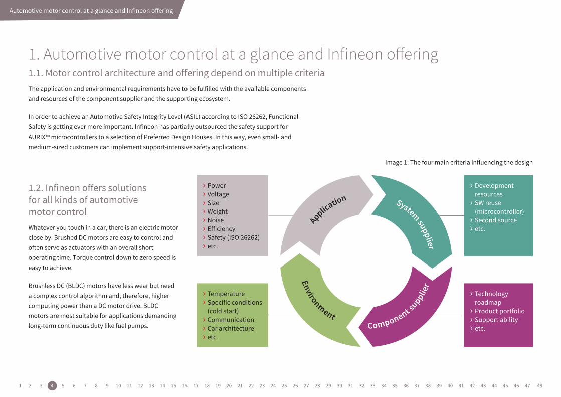
1. Automotive motor control at a glance and Infineon offering1.1. Motor control architecture and offering depend on multiple criteriaThe application and environmental requirements have to be fulfilled with the available components and resources of the component supplier and the supporting ecosystem.
In order to achieve an Automotive Safety Integrity Level (ASIL) according to ISO 26262, Functional Safety is getting ever more important. Infineon has partially outsourced the safety support for AURIX™ microcontrollers to a selection of Preferred Design Houses. In this way, even small- and medium-sized customers can implement support-intensive safety applications.
1.2. Infineon offers solutions for all kinds of automotive motor controlWhatever you touch in a car, there is an electric motor close by. Brushed DC motors are easy to control and often serve as actuators with an overall short operating time. Torque control down to zero speed is easy to achieve.
Brushless DC (BLDC) motors have less wear but need a complex control algorithm and, therefore, higher computing power than a DC motor drive. BLDC motors are most suitable for applications demanding long-term continuous duty like fuel pumps.
Image 1: The four main criteria influencing the design
Environment Component s
upplier
› Power› Voltage› Size› Weight› Noise› Eiciency› Safety (ISO 26262)› etc.
› Temperature› Specific conditions (cold start)› Communication› Car architecture› etc.
› Development resources› SW reuse (microcontroller)› Second source› etc.
› Technology roadmap› Product portfolio› Support ability› etc.
Application System supplier
1 2 3 4 5 6 7 8 9 10 11 12 13 14 15 16 17 18 19 20 21 22 23 24 25 26 27 28 29 30 31 32 33 34 35 36 37 38 39 40 41 42 43 44 45 46 47 48
Automotive motor control at a glance and Infineon offering
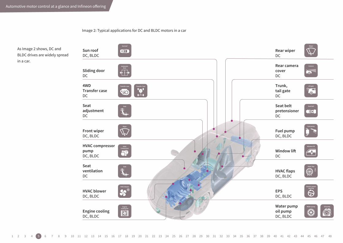
As Image 2 shows, DC and BLDC drives are widely spread in a car.
Image 2: Typical applications for DC and BLDC motors in a car
4WDTransfer caseDC
Rear wiperDC
Fuel pumpDC, BLDC
Window liDC
HVAC flapsDC, BLDC
EPSDC, BLDC
Rear cameracoverDC
Trunk,tail gateDC
Seat beltpretensionerDC
Water pumpoil pumpDC, BLDC
Sliding doorDC
Sun roofDC, BLDC
Front wiperDC, BLDC
HVAC blowerDC, BLDC
Engine coolingDC, BLDC
SeatadjustmentDC
HVAC compressorpumpDC, BLDC
SeatventilationDC
1 2 3 4 5 6 7 8 9 10 11 12 13 14 15 16 17 18 19 20 21 22 23 24 25 26 27 28 29 30 31 32 33 34 35 36 37 38 39 40 41 42 43 44 45 46 47 48
Automotive motor control at a glance and Infineon offering
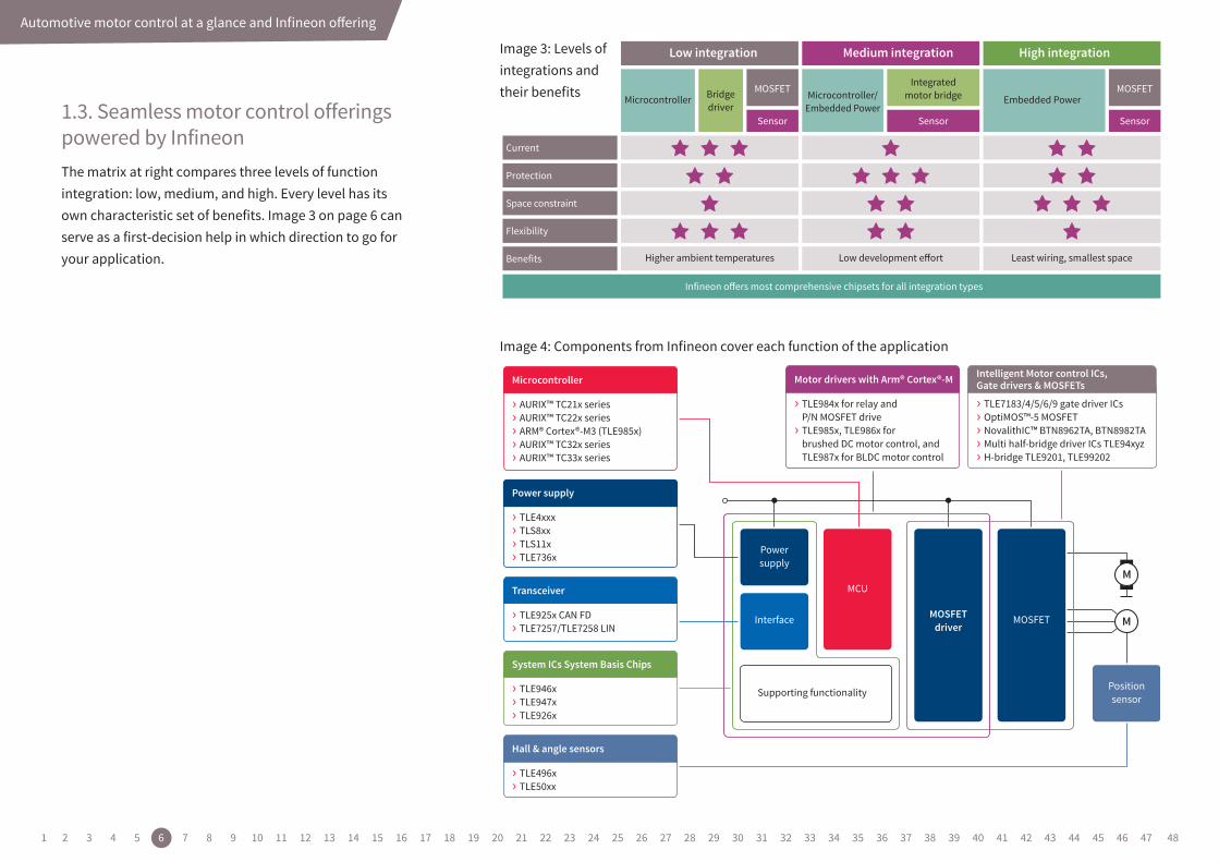
Image 3: Levels of integrations and their benefits
Image 4: Components from Infineon cover each function of the application
1.3. Seamless motor control offerings powered by InfineonThe matrix at right compares three levels of function integration: low, medium, and high. Every level has its own characteristic set of benefits. Image 3 on page 6 can serve as a first-decision help in which direction to go for your application.
MOSFET
Low integration
Current
Sensor Sensor Sensor
Medium integration
MOSFET
High integration
Protection
Space constraint
Flexibility
Benefits
Microcontroller
Higher ambient temperatures
Bridgedriver
Microcontroller/Embedded Power
Integratedmotor bridge Embedded Power
Infineon oers most comprehensive chipsets for all integration types
Low development eort Least wiring, smallest space
M
M
Motor drivers with Arm® Cortex®-M
› TLE984x for relay and P/N MOSFET drive› TLE985x, TLE986x for brushed DC motor control, and TLE987x for BLDC motor control
Power supply
› TLE4xxx› TLS8xx› TLS11x› TLE736x
Transceiver
› TLE925x CAN FD› TLE7257/TLE7258 LIN
System ICs System Basis Chips
› TLE946x› TLE947x› TLE926x
Hall & angle sensors
› TLE496x› TLE50xx
Microcontroller
› AURIX™ TC21x series› AURIX™ TC22x series› ARM® Cortex®-M3 (TLE985x)› AURIX™ TC32x series› AURIX™ TC33x series
Powersupply
Positionsensor
MCU
MOSFETdriver
MOSFETInterface
Supporting functionality
Intelligent Motor control ICs, Gate drivers & MOSFETs
› TLE7183/4/5/6/9 gate driver ICs› OptiMOS™-5 MOSFET› NovalithIC™ BTN8962TA, BTN8982TA› Multi half-bridge driver ICs TLE94xyz › H-bridge TLE9201, TLE99202
1 2 3 4 5 6 7 8 9 10 11 12 13 14 15 16 17 18 19 20 21 22 23 24 25 26 27 28 29 30 31 32 33 34 35 36 37 38 39 40 41 42 43 44 45 46 47 48
High-integrated solutions for compact motor control designs
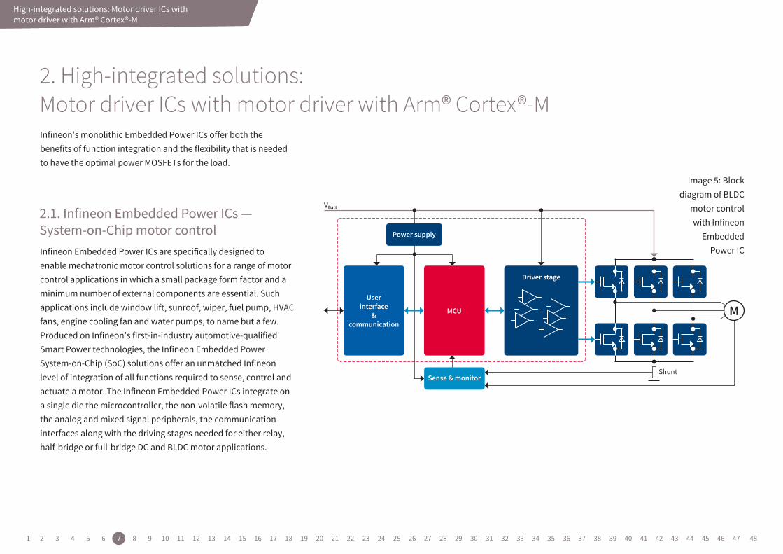
Infineon’s monolithic Embedded Power ICs offer both the benefits of function integration and the flexibility that is needed to have the optimal power MOSFETs for the load.
Infineon Embedded Power ICs are specifically designed to enable mechatronic motor control solutions for a range of motor control applications in which a small package form factor and a minimum number of external components are essential. Such applications include window lift, sunroof, wiper, fuel pump, HVAC fans, engine cooling fan and water pumps, to name but a few. Produced on Infineon’s first-in-industry automotive-qualified Smart Power technologies, the Infineon Embedded Power System-on-Chip (SoC) solutions offer an unmatched Infineon level of integration of all functions required to sense, control and actuate a motor. The Infineon Embedded Power ICs integrate on a single die the microcontroller, the non-volatile flash memory, the analog and mixed signal peripherals, the communication interfaces along with the driving stages needed for either relay, half-bridge or full-bridge DC and BLDC motor applications.
Image 5: Block diagram of BLDC
motor control with Infineon
Embedded Power IC
MCU
User interface
& communication
Driverstage
M
Powersupply
VBatt
Sense&monitorShunt
High-integrated solutions: Motor driver ICs with motor driver with Arm® Cortex®-M
2.1. Infineon Embedded Power ICs — System-on-Chip motor control
2. High-integrated solutions: Motor driver ICs with motor driver with Arm® Cortex®-M
1 2 3 4 5 6 7 8 9 10 11 12 13 14 15 16 17 18 19 20 21 22 23 24 25 26 27 28 29 30 31 32 33 34 35 36 37 38 39 40 41 42 43 44 45 46 47 48

High-integrated solutions: Motor driver ICs with motor driver with Arm® Cortex®-M
› Window lift › Sunroof › Wiper › Engine cooling fan
› Fuel pump › Oil pump › Water pump › HVAC blower
› Enable cost and board space improvements – our system-on-chip solution integrates data processing, actuation and sensing. The chip comes in a leadless VQFN package with 7 x 7 mm footprint and enables PCB space saving. The Embedded Power IC families allow driving of relays and MOSFETs at VBatt > 6 V without external components, providing very cost effective solution on a system level.
› Enabling high levels of system reliability – extensive diagnostics and protections are embedded within the system-on-chip, more than a discrete approach can offer. In addition both the Embedded Power IC and the external MOSFETs can be protected. › Support multiple and flexible designs with minimal effort – all Embedded Power IC are software compatible, maximizing a single design through scalability.
Applications
Key features & benefits
1 2 3 4 5 6 7 8 9 10 11 12 13 14 15 16 17 18 19 20 21 22 23 24 25 26 27 28 29 30 31 32 33 34 35 36 37 38 39 40 41 42 43 44 45 46 47 48
Drivesapplication
> 12 V(trucks; 48 V)
12 V(cars)
Safety class(ASIL C, D)
Safety class(ASIL QM, AB)
CAN-interface
LIN, PWM-interface
Brushlessmotor (DC)
Brushedmotor (DC)
Semi-conductor
driven
Embedded PowerTLE986x/TLE9845/TLE985x
Embedded PowerTLE987x
MOSFET
SensorMOSFET
Sensor
MOSFET
Sensor
Embedded PowerTLE9842/3/4
Discrete bridgedrives
Microcontroller
DC-DC
MOSFET
Sensor
Discrete Embedded Power
SBC, L-chip,transceiver
Relaydriven
High-integrated solutions: Motor driver ICs with motor driver with Arm® Cortex®-M
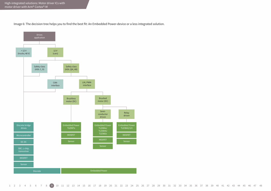
Image 6: The decision tree helps you to find the best fit: An Embedded Power-device or a less integrated solution.
1 2 3 4 5 6 7 8 9 10 11 12 13 14 15 16 17 18 19 20 21 22 23 24 25 26 27 28 29 30 31 32 33 34 35 36 37 38 39 40 41 42 43 44 45 46 47 48
High-integrated solutions for compact motor control designs
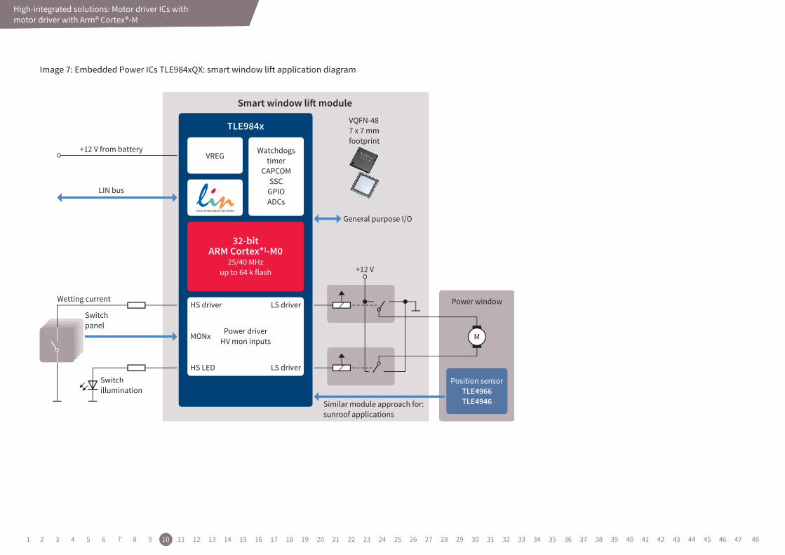
Image 7: Embedded Power ICs TLE984xQX: smart window lift application diagram
High-integrated solutions: Motor driver ICs with motor driver with Arm® Cortex®-M
Power driverHV mon inputs
32-bitARM Cortex*)-M0
25/40 MHzup to 64 k flash
Watchdogstimer
CAPCOMSSC
GPIOADCs
VREG
LS driver
LS driver
HS driver
HS LED
MONx M
+12 V
General purpose I/O
Smart window li module
Similar module approach for:sunroof applications
Position sensorTLE4966TLE4946
Power window
LIN bus
+12 V from battery
TLE984x VQFN-487 x 7 mmfootprint
Switchillumination
Switchpanel
Wetting current
1 2 3 4 5 6 7 8 9 10 11 12 13 14 15 16 17 18 19 20 21 22 23 24 25 26 27 28 29 30 31 32 33 34 35 36 37 38 39 40 41 42 43 44 45 46 47 48
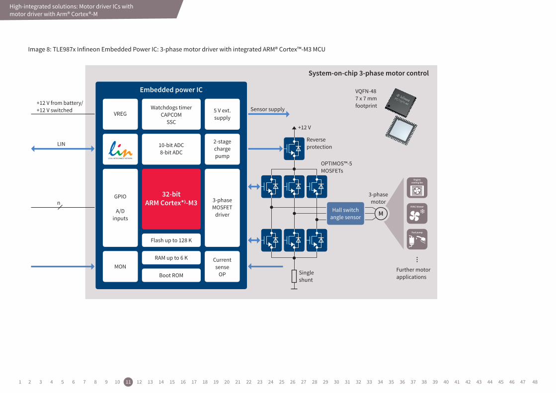
Image 8: TLE987x Infineon Embedded Power IC: 3-phase motor driver with integrated ARM® Cortex™-M3 MCU
VQFN-487 x 7 mmfootprint
32-bitARM Cortex*)-M3
Embedded power IC
Watchdogs timerCAPCOM
SSC
10-bit ADC8-bit ADC
Flash up to 128 K
RAM up to 6 K
Boot ROM
VREG 5 V ext.supply
2-stagechargepump
MONCurrentsense
OP
GPIO
A/Dinputs
3-phaseMOSFET
driver
LIN
n
+12 V from battery/+12 V switched
M
3-phasemotor
Further motorapplications
Singleshunt
Reverseprotection
OPTIMOS™-5MOSFETs
+12 V
Sensor supply
System-on-chip 3-phase motor control
Hall switchangle sensor
High-integrated solutions: Motor driver ICs with motor driver with Arm® Cortex®-M
1 2 3 4 5 6 7 8 9 10 11 12 13 14 15 16 17 18 19 20 21 22 23 24 25 26 27 28 29 30 31 32 33 34 35 36 37 38 39 40 41 42 43 44 45 46 47 48
High-integrated solutions: Motor driver ICs with motor driver with Arm® Cortex®-M
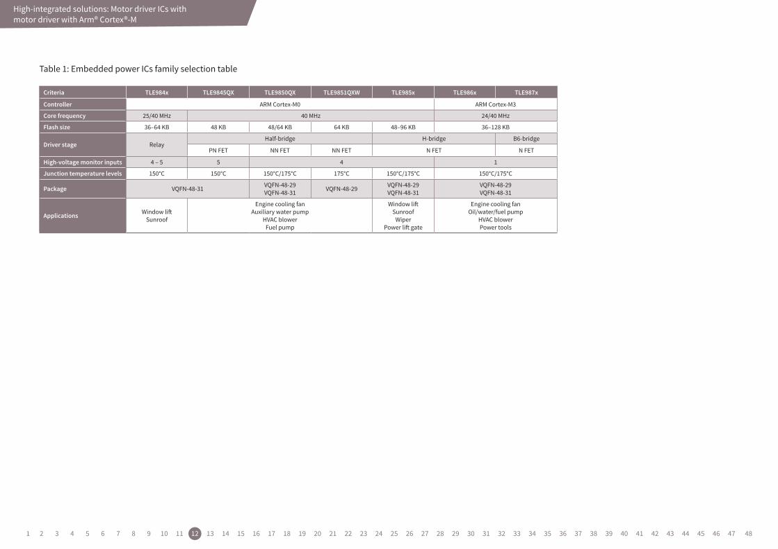
Criteria TLE984x TLE9845QX TLE9850QX TLE9851QXW TLE985x TLE986x TLE987x
Controller ARM Cortex-M0 ARM Cortex-M3
Core frequency 25/40 MHz 40 MHz 24/40 MHz
Flash size 36–64 KB 48 KB 48/64 KB 64 KB 48–96 KB 36–128 KB
Driver stage RelayHalf-bridge H-bridge B6-bridge
PN FET NN FET NN FET N FET N FET
High-voltage monitor inputs 4 – 5 5 4 1
Junction temperature levels 150°C 150°C 150°C/175°C 175°C 150°C/175°C 150°C/175°C
Package VQFN-48-31 VQFN-48-29VQFN-48-31 VQFN-48-29 VQFN-48-29
VQFN-48-31VQFN-48-29VQFN-48-31
Applications Window liftSunroof
Engine cooling fanAuxiliary water pump
HVAC blowerFuel pump
Window liftSunroof
WiperPower lift gate
Engine cooling fanOil/water/fuel pump
HVAC blowerPower tools
Table 1: Embedded power ICs family selection table
1 2 3 4 5 6 7 8 9 10 11 12 13 14 15 16 17 18 19 20 21 22 23 24 25 26 27 28 29 30 31 32 33 34 35 36 37 38 39 40 41 42 43 44 45 46 47 48
High-integrated solutions: Motor driver ICs with motor driver with Arm® Cortex®-M
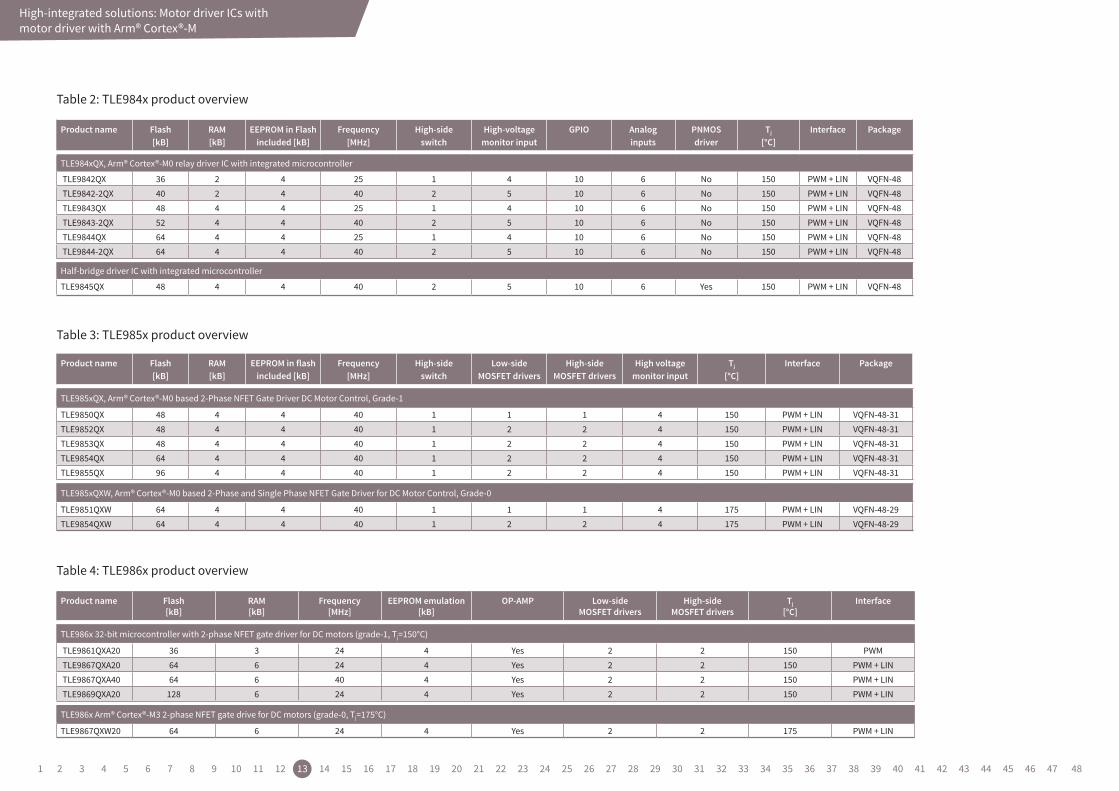
Table 4: TLE986x product overview
Product name Flash [kB]
RAM [kB]
EEPROM in flash included [kB]
Frequency [MHz]
High-side switch
Low-side MOSFET drivers
High-side MOSFET drivers
High voltage monitor input
Tj
[°C]Interface Package
TLE985xQX, Arm® Cortex®-M0 based 2-Phase NFET Gate Driver DC Motor Control, Grade-1
TLE9850QX 48 4 4 40 1 1 1 4 150 PWM + LIN VQFN-48-31TLE9852QX 48 4 4 40 1 2 2 4 150 PWM + LIN VQFN-48-31TLE9853QX 48 4 4 40 1 2 2 4 150 PWM + LIN VQFN-48-31TLE9854QX 64 4 4 40 1 2 2 4 150 PWM + LIN VQFN-48-31TLE9855QX 96 4 4 40 1 2 2 4 150 PWM + LIN VQFN-48-31
TLE985xQXW, Arm® Cortex®-M0 based 2-Phase and Single Phase NFET Gate Driver for DC Motor Control, Grade-0
TLE9851QXW 64 4 4 40 1 1 1 4 175 PWM + LIN VQFN-48-29TLE9854QXW 64 4 4 40 1 2 2 4 175 PWM + LIN VQFN-48-29
Product name Flash [kB]
RAM [kB]
EEPROM in Flash included [kB]
Frequency [MHz]
High-sideswitch
High-voltagemonitor input
GPIO Analoginputs
PNMOSdriver
Tj
[°C]Interface Package
TLE984xQX, Arm® Cortex®-M0 relay driver IC with integrated microcontroller
TLE9842QX 36 2 4 25 1 4 10 6 No 150 PWM + LIN VQFN-48TLE9842-2QX 40 2 4 40 2 5 10 6 No 150 PWM + LIN VQFN-48TLE9843QX 48 4 4 25 1 4 10 6 No 150 PWM + LIN VQFN-48TLE9843-2QX 52 4 4 40 2 5 10 6 No 150 PWM + LIN VQFN-48TLE9844QX 64 4 4 25 1 4 10 6 No 150 PWM + LIN VQFN-48TLE9844-2QX 64 4 4 40 2 5 10 6 No 150 PWM + LIN VQFN-48
Half-bridge driver IC with integrated microcontroller
TLE9845QX 48 4 4 40 2 5 10 6 Yes 150 PWM + LIN VQFN-48
Table 3: TLE985x product overview
Table 2: TLE984x product overview
Product name Flash[kB]
RAM [kB]
Frequency [MHz]
EEPROM emulation [kB]
OP-AMP Low-sideMOSFET drivers
High-sideMOSFET drivers
Tj [°C]
Interface
TLE986x 32-bit microcontroller with 2-phase NFET gate driver for DC motors (grade-1, Tj=150°C)
TLE9861QXA20 36 3 24 4 Yes 2 2 150 PWMTLE9867QXA20 64 6 24 4 Yes 2 2 150 PWM + LINTLE9867QXA40 64 6 40 4 Yes 2 2 150 PWM + LINTLE9869QXA20 128 6 24 4 Yes 2 2 150 PWM + LIN
TLE986x Arm® Cortex®-M3 2-phase NFET gate drive for DC motors (grade-0, Tj=175°C)
TLE9867QXW20 64 6 24 4 Yes 2 2 175 PWM + LIN
1 2 3 4 5 6 7 8 9 10 11 12 13 14 15 16 17 18 19 20 21 22 23 24 25 26 27 28 29 30 31 32 33 34 35 36 37 38 39 40 41 42 43 44 45 46 47 48
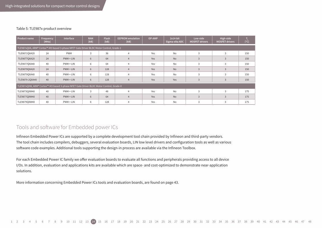
Table 5: TLE987x product overview
High-integrated solutions for compact motor control designs
Product name Frequency [MHz]
Interface RAM [kB]
Flash[kB]
EEPROM emulation [kB]
OP-AMP 2x14-bitSigma-elta ADC
Low-sideMOSFET drivers
High-sideMOSFET drivers
Tj [°C]
TLE987xQXA, ARM® Cortex™-M3 based 3-phase NFET Gate Driver BLDC Motor Control, Grade-1
TLE9871QXA20 24 PWM 3 36 4 Yes No 3 3 150
TLE9877QXA20 24 PWM + LIN 6 64 4 Yes No 3 3 150
TLE9877QXA40 40 PWM + LIN 6 64 4 Yes No 3 3 150
TLE9879QXA20 24 PWM + LIN 6 128 4 Yes No 3 3 150
TLE9879QXA40 40 PWM + LIN 6 128 4 Yes No 3 3 150
TLE9879-2QXA40 40 PWM + LIN 6 128 4 Yes Yes 3 3 150
TLE987xQXW, ARM® Cortex™-M3 based 3-phase NFET Gate Driver BLDC Motor Control, Grade-0
TLE9873QXW40 40 PWM + LIN 3 48 4 Yes No 3 3 175
TLE9877QXW40 40 PWM + LIN 6 64 4 Yes No 3 3 175
TLE9879QXW40 40 PWM + LIN 6 128 4 Yes No 3 3 175
Infineon Embedded Power ICs are supported by a complete development tool chain provided by Infineon and third-party vendors. The tool chain includes compilers, debuggers, several evaluation boards, LIN low level drivers and configu ration tools as well as various software code examples. Additional tools supporting the design-in process are available via the Infineon Toolbox.
For each Embedded Power IC family we offer evaluation boards to evaluate all functions and peripherals providing access to all device I/Os. In addition, evaluation and applications kits are available which are space- and cost-optimized to demonstrate near-application solutions.
More information concerning Embedded Power ICs tools and evaluation boards, are found on page 43.
Tools and software for Embedded power ICs
1 2 3 4 5 6 7 8 9 10 11 12 13 14 15 16 17 18 19 20 21 22 23 24 25 26 27 28 29 30 31 32 33 34 35 36 37 38 39 40 41 42 43 44 45 46 47 48

VS
GND
OUT
SR
IS
IN
INH
High-current half-bridge
PI filter may be necessary to reducesystem-level EMC
I/OI/OI/O I/O
8-bit MCUReset
I/O I
VDD
VSS
Voltage regulator
WO
RO
Q
D
GND
Reverse polarityprotectionPI filter
VS
M
Medium-integrated solutions for motor control: Intelligent Motor Control ICs
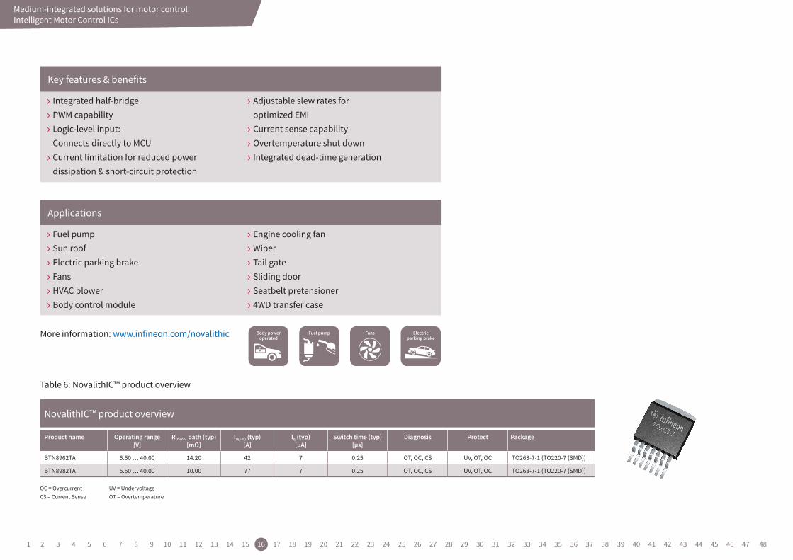
3.1. Single half-bridgesThe integrated high-current motor drivers family NovalithIC™ provides a complete low-ohmic-protected half-bridge in a single package. It can be combined with an additional NovalithIC™ to create an h-bridge or 3-phase bridge as well. The NovalithIC™ family has the capability to switch high-frequency PWM while providing overcurrent, overvoltage and overtemperature protection. Other benefits of the NovalithIC™ are:
› High reliability
› Current sense
› Small footprint
› High currents (up to 55 A)
› Scalability due to family concept (BTN8962 and BTN8982)
› Adjustable slew rate
The NovalithIC™ family offers cost-optimized solutions for protected high-current PWM motor drives with very low board-space consumption — scaled to your needs.
The medium-integrated devices combine gate-drivers with the MOSFET power stage in a single package. A small foot-print on the PCB, diagnostic feedback and protection add to the benefits of the integration.
Infineon’s portfolio comprises Single-Half-Bridges, Multi-Half-Bridges and Full- or H-Bridges. Image 9 shows an application example.
3. Medium-integrated solutions for motor control: Intelligent Motor Control ICs
Image 9: Application example of fuel pumppartitioning with high current integrated Half-Bridge
1 2 3 4 5 6 7 8 9 10 11 12 13 14 15 16 17 18 19 20 21 22 23 24 25 26 27 28 29 30 31 32 33 34 35 36 37 38 39 40 41 42 43 44 45 46 47 48
Medium-integrated solutions for motor control
Table 6: NovalithIC™ product overview
› Fuel pump › Sun roof › Electric parking brake › Fans › HVAC blower › Body control module
› Engine cooling fan › Wiper › Tail gate › Sliding door › Seatbelt pretensioner › 4WD transfer case
› Integrated half-bridge › PWM capability › Logic-level input: Connects directly to MCU › Current limitation for reduced power dissipation & short-circuit protection
› Adjustable slew rates for optimized EMI › Current sense capability › Overtemperature shut down › Integrated dead-time generation
Applications
Key features & benefits
NovalithIC™ product overview
Product name Operating range [V]
RDS(on) path (typ) [mΩ]
ID(lim) (typ) [A]
Iq (typ) [µA]
Switch time (typ) [µs]
Diagnosis Protect Package
BTN8962TA 5.50 … 40.00 14.20 42 7 0.25 OT, OC, CS UV, OT, OC TO263-7-1 (TO220-7 (SMD))
BTN8982TA 5.50 … 40.00 10.00 77 7 0.25 OT, OC, CS UV, OT, OC TO263-7-1 (TO220-7 (SMD))
OC = OvercurrentCS = Current Sense
UV = UndervoltageOT = Overtemperature
More information: www.infineon.com/novalithic
Medium-integrated solutions for motor control: Intelligent Motor Control ICs
1 2 3 4 5 6 7 8 9 10 11 12 13 14 15 16 17 18 19 20 21 22 23 24 25 26 27 28 29 30 31 32 33 34 35 36 37 38 39 40 41 42 43 44 45 46 47 48
Medium-integrated solutions for motor control
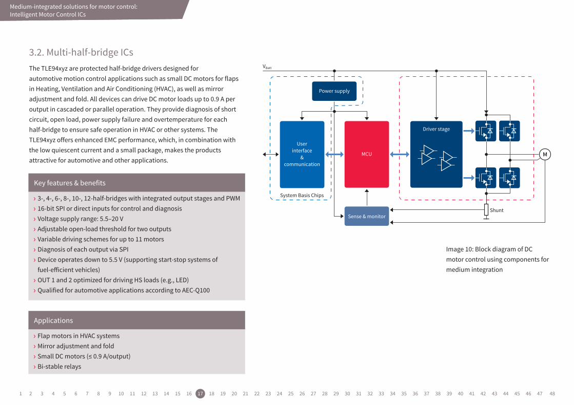
3.2. Multi-half-bridge ICsThe TLE94xyz are protected half-bridge drivers designed for automotive motion control applications such as small DC motors for flaps in Heating, Ventilation and Air Conditioning (HVAC), as well as mirror adjustment and fold. All devices can drive DC motor loads up to 0.9 A per output in cascaded or parallel operation. They provide diagnosis of short circuit, open load, power supply failure and overtemperature for each half-bridge to ensure safe operation in HVAC or other systems. The TLE94xyz offers enhanced EMC performance, which, in combination with the low quiescent current and a small package, makes the products attractive for automotive and other applications.
› Flap motors in HVAC systems › Mirror adjustment and fold › Small DC motors (≤ 0.9 A/output) › Bi-stable relays
› 3-, 4-, 6-, 8-, 10-, 12-half-bridges with integrated output stages and PWM › 16-bit SPI or direct inputs for control and diagnosis › Voltage supply range: 5.5–20 V › Adjustable open-load threshold for two outputs › Variable driving schemes for up to 11 motors › Diagnosis of each output via SPI › Device operates down to 5.5 V (supporting start-stop systems of fuel-efficient vehicles) › OUT 1 and 2 optimized for driving HS loads (e.g., LED) › Qualified for automotive applications according to AEC-Q100
Applications
Key features & benefits
VBatt
Shunt
System Basis Chips
Driver stage
Sense & monitor
Power supply
MCU
Userinterface
&communication
M
Image 10: Block diagram of DCmotor control using components formedium integration
Medium-integrated solutions for motor control: Intelligent Motor Control ICs
1 2 3 4 5 6 7 8 9 10 11 12 13 14 15 16 17 18 19 20 21 22 23 24 25 26 27 28 29 30 31 32 33 34 35 36 37 38 39 40 41 42 43 44 45 46 47 48
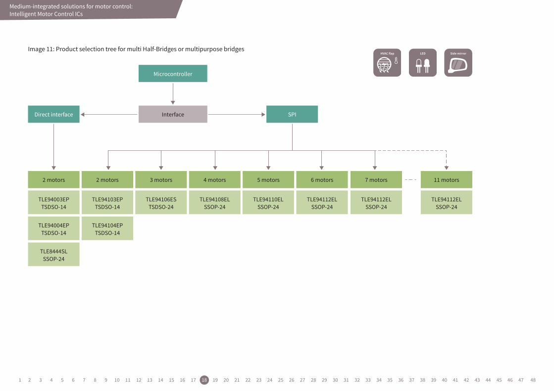
Microcontroller
2 motors 2 motors
TLE94103EPTSDSO-14
TLE94106ESTSDSO-24
TLE94108ELSSOP-24
TLE94110ELSSOP-24
TLE94112ELSSOP-24
TLE94112ELSSOP-24
TLE94104EPTSDSO-14
TLE94003EPTSDSO-14
TLE94004EPTSDSO-14
TLE8444SLSSOP-24
3 motors 4 motors 5 motors 6 motors
TLE94112ELSSOP-24
7 motors 11 motors
InterfaceDirect interface SPI
Medium-integrated solutions for motor control: Intelligent Motor Control ICs
Image 11: Product selection tree for multi Half-Bridges or multipurpose bridges
1 2 3 4 5 6 7 8 9 10 11 12 13 14 15 16 17 18 19 20 21 22 23 24 25 26 27 28 29 30 31 32 33 34 35 36 37 38 39 40 41 42 43 44 45 46 47 48
Medium-integrated solutions for motor control
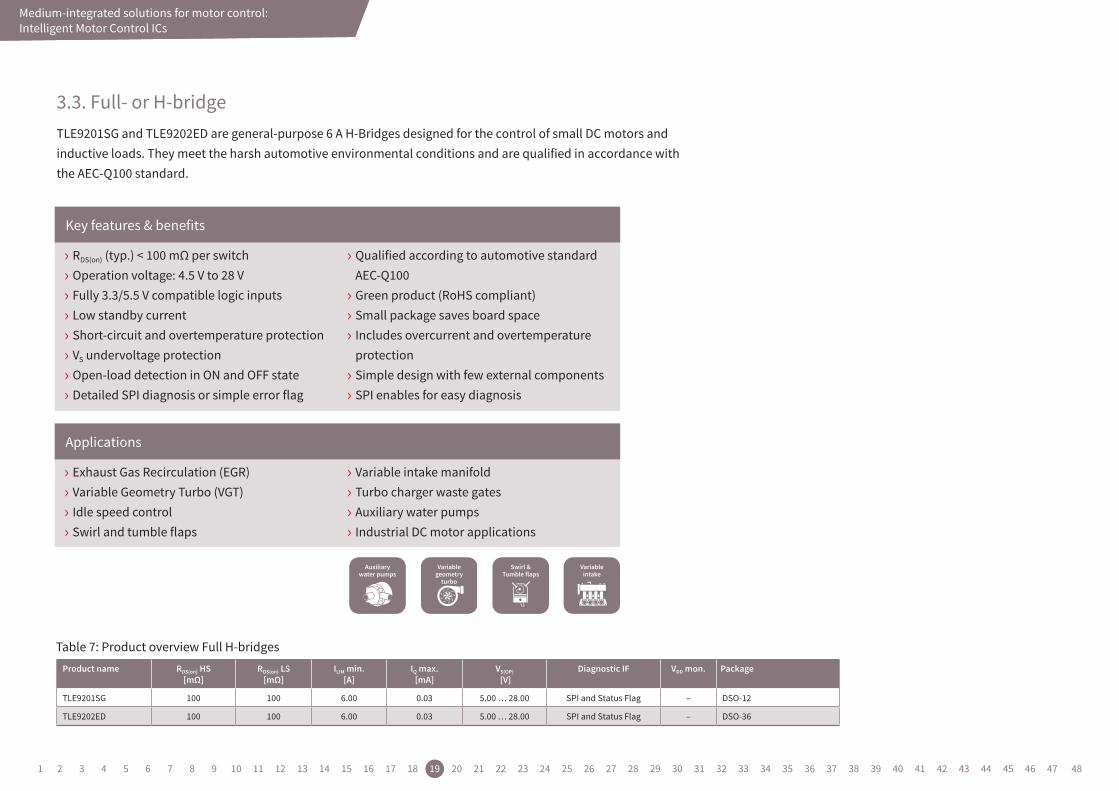
3.3. Full- or H-bridgeTLE9201SG and TLE9202ED are general-purpose 6 A H-Bridges designed for the control of small DC motors and inductive loads. They meet the harsh automotive environmental conditions and are qualified in accordance with the AEC-Q100 standard.
Table 7: Product overview Full H-bridges
› Exhaust Gas Recirculation (EGR) › Variable Geometry Turbo (VGT) › Idle speed control › Swirl and tumble flaps
› Variable intake manifold › Turbo charger waste gates › Auxiliary water pumps › Industrial DC motor applications
› RDS(on) (typ.) < 100 mΩ per switch › Operation voltage: 4.5 V to 28 V › Fully 3.3/5.5 V compatible logic inputs › Low standby current › Short-circuit and overtemperature protection › VS undervoltage protection › Open-load detection in ON and OFF state › Detailed SPI diagnosis or simple error flag
› Qualified according to automotive standard AEC-Q100 › Green product (RoHS compliant) › Small package saves board space › Includes overcurrent and overtemperature protection › Simple design with few external components › SPI enables for easy diagnosis
Applications
Key features & benefits
Product name RDS(on) HS[mΩ]
RDS(on) LS[mΩ]
ILIM min. [A]
IQ max. [mA]
VS(OP)
[V]Diagnostic IF VDD mon. Package
TLE9201SG 100 100 6.00 0.03 5.00 … 28.00 SPI and Status Flag – DSO-12
TLE9202ED 100 100 6.00 0.03 5.00 … 28.00 SPI and Status Flag – DSO-36
Medium-integrated solutions for motor control: Intelligent Motor Control ICs
1 2 3 4 5 6 7 8 9 10 11 12 13 14 15 16 17 18 19 20 21 22 23 24 25 26 27 28 29 30 31 32 33 34 35 36 37 38 39 40 41 42 43 44 45 46 47 48
Medium-integrated solutions for motor control: System ICs
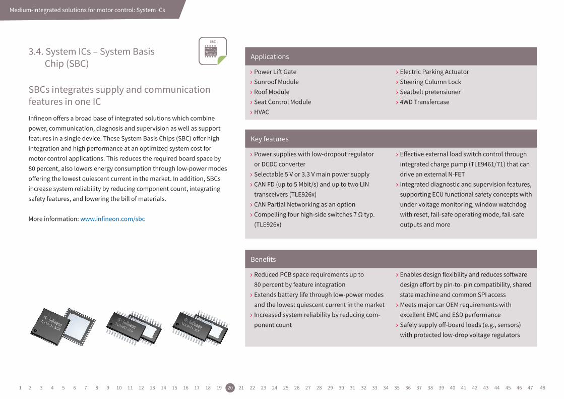
3.4. System ICs – System Basis Chip (SBC)
SBCs integrates supply and communication features in one ICInfineon offers a broad base of integrated solutions which combine power, communication, diagnosis and supervision as well as support features in a single device. These System Basis Chips (SBC) offer high integration and high performance at an optimized system cost for motor control applications. This reduces the required board space by 80 percent, also lowers energy consumption through low-power modes offering the lowest quiescent current in the market. In addition, SBCs increase system reliability by reducing component count, integrating safety features, and lowering the bill of materials.
More information: www.infineon.com/sbc
› Power Lift Gate › Sunroof Module › Roof Module › Seat Control Module › HVAC
› Electric Parking Actuator › Steering Column Lock › Seatbelt pretensioner › 4WD Transfercase
› Power supplies with low-dropout regulator or DCDC converter › Selectable 5 V or 3.3 V main power supply › CAN FD (up to 5 Mbit/s) and up to two LIN transceivers (TLE926x) › CAN Partial Networking as an option › Compelling four high-side switches 7 Ω typ. (TLE926x)
› Effective external load switch control through integrated charge pump (TLE9461/71) that can drive an external N-FET › Integrated diagnostic and supervision features, supporting ECU functional safety concepts with under-voltage monitoring, window watchdog with reset, fail-safe operating mode, fail-safe outputs and more
› Reduced PCB space requirements up to 80 percent by feature integration › Extends battery life through low-power modes and the lowest quiescent current in the market › Increased system reliability by reducing com-ponent count
› Enables design flexibility and reduces software design effort by pin-to- pin compatibility, shared state machine and common SPI access › Meets major car OEM requirements with excellent EMC and ESD performance › Safely supply off-board loads (e.g., sensors) with protected low-drop voltage regulators
Applications
Key features
Benefits
1 2 3 4 5 6 7 8 9 10 11 12 13 14 15 16 17 18 19 20 21 22 23 24 25 26 27 28 29 30 31 32 33 34 35 36 37 38 39 40 41 42 43 44 45 46 47 48
Medium-integrated solutions for motor control: System ICs
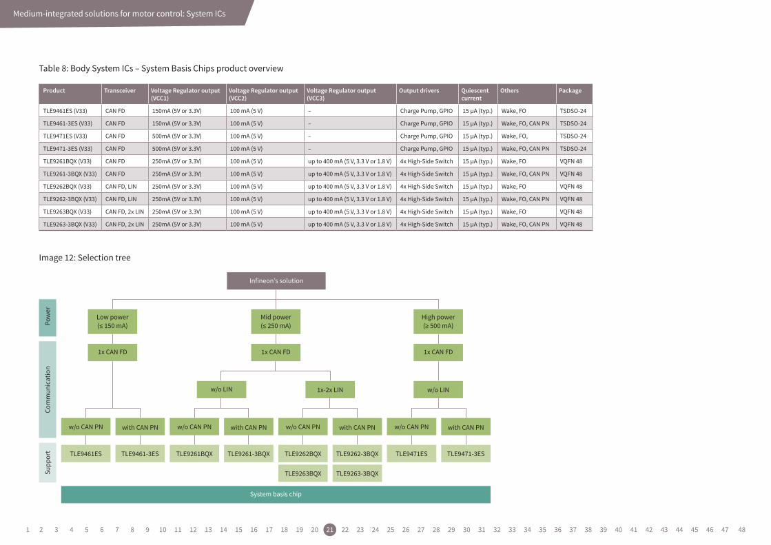
Table 8: Body System ICs – System Basis Chips product overview
Image 12: Selection tree
Product Transceiver Voltage Regulator output (VCC1)
Voltage Regulator output (VCC2)
Voltage Regulator output(VCC3)
Output drivers Quiescent current
Others Package
TLE9461ES (V33) CAN FD 150mA (5V or 3.3V) 100 mA (5 V) – Charge Pump, GPIO 15 µA (typ.) Wake, FO TSDSO-24
TLE9461-3ES (V33) CAN FD 150mA (5V or 3.3V) 100 mA (5 V) – Charge Pump, GPIO 15 µA (typ.) Wake, FO, CAN PN TSDSO-24
TLE9471ES (V33) CAN FD 500mA (5V or 3.3V) 100 mA (5 V) – Charge Pump, GPIO 15 µA (typ.) Wake, FO, TSDSO-24
TLE9471-3ES (V33) CAN FD 500mA (5V or 3.3V) 100 mA (5 V) – Charge Pump, GPIO 15 µA (typ.) Wake, FO, CAN PN TSDSO-24
TLE9261BQX (V33) CAN FD 250mA (5V or 3.3V) 100 mA (5 V) up to 400 mA (5 V, 3.3 V or 1.8 V) 4x High-Side Switch 15 µA (typ.) Wake, FO VQFN 48
TLE9261-3BQX (V33) CAN FD 250mA (5V or 3.3V) 100 mA (5 V) up to 400 mA (5 V, 3.3 V or 1.8 V) 4x High-Side Switch 15 µA (typ.) Wake, FO, CAN PN VQFN 48
TLE9262BQX (V33) CAN FD, LIN 250mA (5V or 3.3V) 100 mA (5 V) up to 400 mA (5 V, 3.3 V or 1.8 V) 4x High-Side Switch 15 µA (typ.) Wake, FO VQFN 48
TLE9262-3BQX (V33) CAN FD, LIN 250mA (5V or 3.3V) 100 mA (5 V) up to 400 mA (5 V, 3.3 V or 1.8 V) 4x High-Side Switch 15 µA (typ.) Wake, FO, CAN PN VQFN 48
TLE9263BQX (V33) CAN FD, 2x LIN 250mA (5V or 3.3V) 100 mA (5 V) up to 400 mA (5 V, 3.3 V or 1.8 V) 4x High-Side Switch 15 µA (typ.) Wake, FO VQFN 48
TLE9263-3BQX (V33) CAN FD, 2x LIN 250mA (5V or 3.3V) 100 mA (5 V) up to 400 mA (5 V, 3.3 V or 1.8 V) 4x High-Side Switch 15 µA (typ.) Wake, FO, CAN PN VQFN 48
Infineon’s solution
Supp
ort
Pow
erCo
mm
unic
atio
n
System basis chip
Low power(≤ 150 mA)
Mid power(≤ 250 mA)
1x CAN FD 1x CAN FD1x CAN FD
High power(≥ 500 mA)
w/o CAN PN
TLE9461ES TLE9461-3ES TLE9471ES TLE9471-3ES
with CAN PN
w/o LIN 1x-2x LIN w/o LIN
w/o CAN PN with CAN PN
TLE9261BQX TLE9261-3BQX TLE9262BQX TLE9262-3BQX
TLE9263BQX TLE9263-3BQX
w/o CAN PN with CAN PN w/o CAN PN with CAN PN
1 2 3 4 5 6 7 8 9 10 11 12 13 14 15 16 17 18 19 20 21 22 23 24 25 26 27 28 29 30 31 32 33 34 35 36 37 38 39 40 41 42 43 44 45 46 47 48

Low-integrated solutions for high-power motor control
4. Low-integrated solutions for high-power motor controlThe low-integrated solution with discrete components gives you the flexibility of selecting the optimal device for each function. The result is a tailor-made design that fits the application like a glove. Especially, high-current drives benefit from the use of the latest MOSFETs with the lowest RDS(on) in thermally optimized packages.
Have a look at gate-drivers, power MOSFETs, voltage regulators for power supply, transceivers for communication over LIN or CAN, Hall sensors and microcontrollers. Image 13 shows an application example of a 3-phase motor drive using discrete components resulting in a low integration level, while providing the highest flexibility.
Image 13: Simplified block diagram of a 3-phase motor drive using discrete components
THS3
C3C2C1
CSHx
TLS3
THS2
TLS2
RShunt3RShunt2RShunt1
CCP1
THS1
TLS1RGLxGLx
SHx
AGND GND
GNDGND P-GND
CPGND
SLx
3*
ISPx
ISNx
GHx
VDHP
CL1
CH1
CB
BHx
VDHx
D1
MOSI
SOFF
INH
VS
CLK_SPICSN
MISO
IHxILx
ENA
VCC
ERR
PFBx
VRO
VOx
CCP2
CCB
CVS
CL2
CH2
SHx
SHx CB
RGHx
CPI1 CPI2
LPIVBatt
VCC
Current sense block
Floating LS driverincl. diagnostics
3*
3* BHx
Floating HS driverincl. diagnostics
Power supplyincl. diagnostic and safety functions
Configuration registerscontrol registers
read registers
DiagnosticsFailure detection
Direct inputcontrol
Leve
l shi
SPI interface
I/Oports
Microcontroller(e.g. TC23x)
Microcontrollersupply IC
(e.g. TLF35584)
GND
1 2 3 4 5 6 7 8 9 10 11 12 13 14 15 16 17 18 19 20 21 22 23 24 25 26 27 28 29 30 31 32 33 34 35 36 37 38 39 40 41 42 43 44 45 46 47 48
Low-integrated solutions for high-power motor control
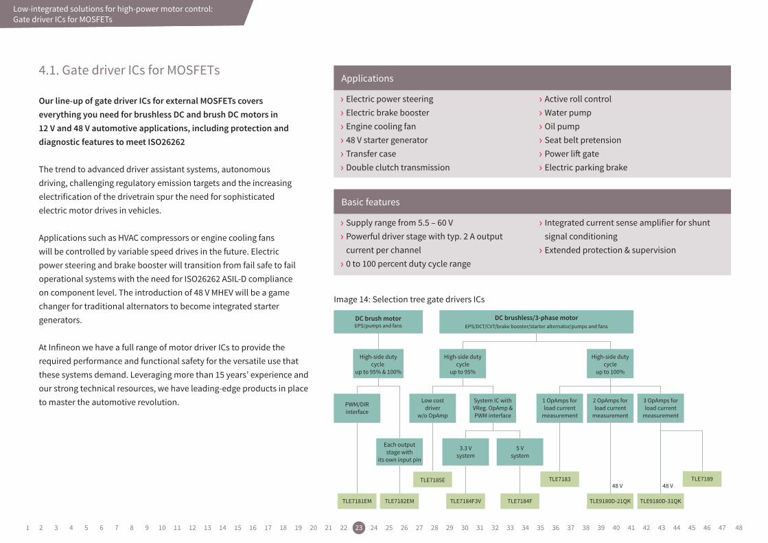
4.1. Gate driver ICs for MOSFETs
Low-integrated solutions for high-power motor control: Gate driver ICs for MOSFETs
› Electric power steering › Electric brake booster › Engine cooling fan › 48 V starter generator › Transfer case › Double clutch transmission
› Active roll control › Water pump › Oil pump › Seat belt pretension › Power lift gate › Electric parking brake
› Supply range from 5.5 – 60 V › Powerful driver stage with typ. 2 A output current per channel › 0 to 100 percent duty cycle range
› Integrated current sense amplifier for shunt signal conditioning › Extended protection & supervision
Applications
Basic features
DC brush motorEPS/pumps and fans
DC brushless/3-phase motorEPS/DCT/CVT/brake booster/starter alternator/pumps and fans
High-side dutycycle
up to 95%
High-side dutycycle
up to 95% & 100%
Low costdriver
w/o OpAmp
System IC withVReg. OpAmp &PWM interface
High-side dutycycle
up to 100%
3 OpAmps forload current
measurement
2 OpAmps forload current
measurement
1 OpAmps forload current
measurement
3.3 Vsystem
5 Vsystem
PWM/DIRinterface
Each outputstage with
its own input pin
TLE7181EM TLE7182EM
TLE7185E
TLE7184F3V TLE7184F
TLE7183
TLE9180D-21QK
48 V
TLE9180D-31QK
TLE718948 V
Image 14: Selection tree gate drivers ICs
Our line-up of gate driver ICs for external MOSFETs covers everything you need for brushless DC and brush DC motors in 12 V and 48 V automotive applications, including protection and diagnostic features to meet ISO26262
The trend to advanced driver assistant systems, autonomous driving, challenging regulatory emission targets and the increasing electrification of the drivetrain spur the need for sophisticated electric motor drives in vehicles.
Applications such as HVAC compressors or engine cooling fans will be controlled by variable speed drives in the future. Electric power steering and brake booster will transition from fail safe to fail operational systems with the need for ISO26262 ASIL-D compliance on component level. The introduction of 48 V MHEV will be a game changer for traditional alternators to become integrated starter generators.
At Infineon we have a full range of motor driver ICs to provide the required performance and functional safety for the versatile use that these systems demand. Leveraging more than 15 years’ experience and our strong technical resources, we have leading-edge products in place to master the automotive revolution.
1 2 3 4 5 6 7 8 9 10 11 12 13 14 15 16 17 18 19 20 21 22 23 24 25 26 27 28 29 30 31 32 33 34 35 36 37 38 39 40 41 42 43 44 45 46 47 48
Low-integrated solutions for high-power motor control
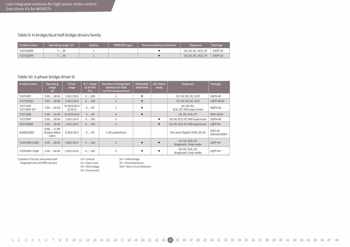
Table 9: H-bridge/dual half-bridge drivers family
Low-integrated solutions for high-power motor control: Gate driver ICs for MOSFETs
Product name Operating range
[V]
Drives stage
D.C.-range @ 20 kHz
[%]
Numbers of integrated OpAmps for load
current measurement
Adjustable dead time
ISO 26262 ready
Diagnosis Package
TLE7183F 5.50 … 28.00 1.50/1.50 A 0 … 100 1 l OT, UV, OV, OC, OCD VQFN-48
TLE7183QU 5.50 … 28.00 1.50/1.50 A 0 … 100 1 l OT, UV, OV, OC, SCD TQFP-48 EP
TLE7184FTLE7184F-3V1) 7.00 … 32.00 12.50/9.00 Ω
12.50 Ω 0 … 95 1 lUV, OV, OC,
SCD, OT, VDD supervision VQFN-48
TLE7185E 5.50 … 32.00 12.50/9.00 Ω 0 … 95 0 l UV, OV, SCD, OT DSO-36 EP
TLE7189F 5.50 … 28.00 1.50/1.50 A 0 … 100 3 l UV, OV, SCD, OT, VDD supervision VQFN-48
TLE7189QK 5.50 … 28.00 1.50/1.50 A 0 … 100 3 l UV, OV, SCD, OT, VDD supervision LQFP-64
AUIRS203028.00 … 17.00Output offset
200 V0.20/0.35 A 0 … 95 1 (SC protection) One error flag for OTW, UV, SC DSO-28
(28 lead SOIC)
TLE9180D-21QK 5.50 … 60.00 2.00/2.20 A 0 … 100 2 l lUV, OV, SCD, OT,
diagnostic, limp mode LQFP-64
TLE9180D-31QK 5.50 … 60.00 2.00/2.20 A 0 … 100 3 l lUV, OV, SCD, OT,
diagnostic, limp mode LQFP-64
Product name Operating range [V] OpAmp PWM/DIR input Reverse polarity protection Diagnosis Package
TLE7181EM 7 … 34 1 l UV, OV, OC, SCD, OT SSOP-24
TLE7182EM 7 … 34 1 l UV, OV, OC, SCD, OT SSOP-24
LO = LockoutOL = Open-LoadOV = OvervoltageOC = Overcurrent
UV = UndervoltageOT = OvertemperatureSCD = Short-Circuit Detection
1) System IC for fans and pumps with integrated LDO and PWM interface
Table 10: 3-phase bridge driver IC
1 2 3 4 5 6 7 8 9 10 11 12 13 14 15 16 17 18 19 20 21 22 23 24 25 26 27 28 29 30 31 32 33 34 35 36 37 38 39 40 41 42 43 44 45 46 47 48
Low-integrated solutions for high-power motor control
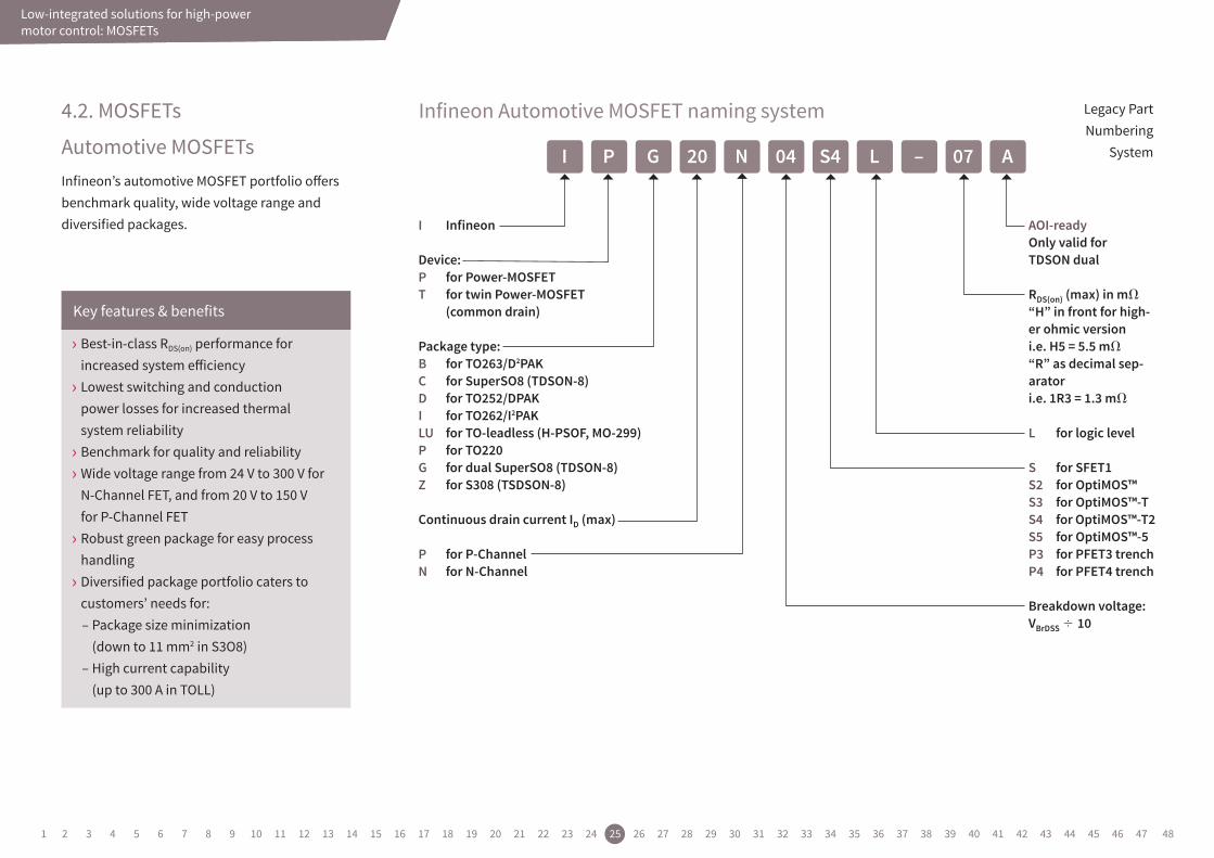
4.2. MOSFETs
Automotive MOSFETsInfineon’s automotive MOSFET portfolio offers benchmark quality, wide voltage range and diversified packages.
Legacy Part Numbering
System
Infineon Automotive MOSFET naming system
I NG S4 07P 04 –20 L A
I Infineon
Device:P forPower-MOSFETT fortwinPower-MOSFET
(commondrain)
Packagetype:B forTO263/D2PAKC forSuperSO8(TDSON-8)D forTO252/DPAKI forTO262/I2PAKLU forTO-leadless(H-PSOF,MO-299)P forTO220G fordualSuperSO8(TDSON-8)Z forS308(TSDSON-8)
ContinuousdraincurrentID(max)
P forP-ChannelN forN-Channel
AOI-ready Onlyvalidfor TDSONdual
RDS(on)(max)inm
“H”infrontforhigh-erohmicversion i.e.H5=5.5m
“R”asdecimalsep-arator i.e.1R3=1.3m
L forlogiclevel
S forSFET1S2 forOptiMOS™S3 forOptiMOS™-TS4 forOptiMOS™-T2S5 forOptiMOS™-5P3 forPFET3trenchP4 forPFET4trench
Breakdownvoltage:VBrDSS 10
Low-integrated solutions for high-power motor control: MOSFETs
› Best-in-class RDS(on) performance for increased system efficiency › Lowest switching and conduction power losses for increased thermal system reliability › Benchmark for quality and reliability › Wide voltage range from 24 V to 300 V for N-Channel FET, and from 20 V to 150 V for P-Channel FET › Robust green package for easy process handling › Diversified package portfolio caters to customers’ needs for:
– Package size minimization (down to 11 mm2 in S3O8)
– High current capability (up to 300 A in TOLL)
Key features & benefits
1 2 3 4 5 6 7 8 9 10 11 12 13 14 15 16 17 18 19 20 21 22 23 24 25 26 27 28 29 30 31 32 33 34 35 36 37 38 39 40 41 42 43 44 45 46 47 48
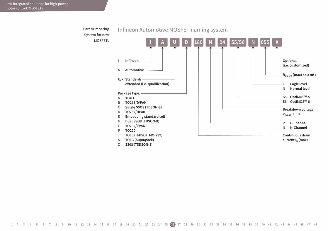
I Infineon
A Automotive
U/X Standard/ extended(i.e.qualification)
Packagetype:A sTOLLB TO263/D2PAKC SingleSSO8(TDSON-8)D TO252/DPAKE EmbeddingstandardcellG DualSSO8(TDSON-8)I TO262/I2PAKP TO220T TOLL(H-PSOF,MO-299)S TOLG(SupIRpack)Z S308(TSDSON-8)
Low-integrated solutions for high-power motor control
Part Numbering System for new
MOSFETs
Infineon Automotive MOSFET naming system
I 180U 04 055A N ND S5/S6 X
Optional (i.e.customized)
RDS(on)(max)xx.xm
L LogiclevelN Normallevel
S5 OptiMOS™-5 S6 OptiMOS™-6
Breakdownvoltage:VBrDSS 10
P P-ChannelN N-Channel
ContinuousdraincurrentID(max)
Low-integrated solutions for high-power motor control: MOSFETs
1 2 3 4 5 6 7 8 9 10 11 12 13 14 15 16 17 18 19 20 21 22 23 24 25 26 27 28 29 30 31 32 33 34 35 36 37 38 39 40 41 42 43 44 45 46 47 48
Low-integrated solutions for high-power motor controlLow-integrated solutions for high-power motor control: MOSFETs
Sales name Technology RDS(on) max 10 V [mΩ]
ID
[A]LL/NL Package
NEW IAUC120N04S6L008 OptiMOS™ 6 0.8 120 LL Single SS08
NEW IAUC120N04S6N009 OptiMOS™ 6 0.9 120 NL Single SS08
NEW IAUC120N04S6L009 OptiMOS™ 6 0.9 120 LL Single SS08
NEW IAUC120N04S6N010 OptiMOS™ 6 1.0 120 NL Single SS08
NEW IAUC120N04S6L012 OptiMOS™ 6 1.2 120 LL Single SS08
NEW IAUC120N04S6N013 OptiMOS™ 6 1.3 120 NL Single SS08
NEW IAUC100N04S6L014 OptiMOS™ 6 1.4 100 LL Single SS08
NEW IAUC100N04S6N015 OptiMOS™ 6 1.5 100 NL Single SS08
NEW IAUC100N04S6L020 OptiMOS™ 6 2.0 100 LL Single SS08
NEW IAUC100N04S6N022 OptiMOS™ 6 2.2 100 NL Single SS08
NEW IAUC100N04S6L025 OptiMOS™ 6 2.5 100 LL Single SS08
NEW IAUC100N04S6N028 OptiMOS™ 6 2.8 100 NL Single SS08
NEW IAUC80N04S6L032 OptiMOS™ 6 3.2 80 LL Single SS08
NEW IAUC80N04S6N036 OptiMOS™ 6 3.6 80 NL Single SS08
NEW IAUC60N04S6L039 OptiMOS™ 6 3.9 60 LL Single SS08
NEW IAUC60N04S6N044 OptiMOS™ 6 4.4 60 NL Single SS08
NEW IAUC100N10S5L040 OptiMOS™ 5 4.0 100 LL Single SS08
NEW IAUC100N10S5N040 OptiMOS™ 5 4.0 100 NL Single SS08
NEW IAUC100N08S5N031 OptiMOS™ 5 3.1 100 NL Single SS08
NEW IAUC100N08S5N043 OptiMOS™ 5 4.3 100 NL Single SS08
NEW IAUC70N08S5N074 OptiMOS™ 5 7.4 70 NL Single SS08
IPC100N04S5-1R2 OptiMOS™ 5 1.2 100 NL Single SS08
IPC100N04S5L-1R1 OptiMOS™ 5 1.1 100 LL Single SS08
IPC100N04S5-1R7 OptiMOS™ 5 1.7 100 NL Single SS08
IPC100N04S5L-1R5 OptiMOS™ 5 1.5 100 LL Single SS08
IPC100N04S5-1R9 OptiMOS™ 5 1.9 100 NL Single SS08
IPC100N04S5L-1R9 OptiMOS™ 5 1.9 100 LL Single SS08
IPC100N04S5-2R8 OptiMOS™ 5 2.8 100 NL Single SS08
IPC100N04S5L-2R6 OptiMOS™ 5 2.6 100 LL Single SS08
IPC90N04S5-3R6 OptiMOS™ 5 3.6 90 NL Single SS08
IPC90N04S5L-3R3 OptiMOS™ 5 3.3 90 LL Single SS08
IPC70N04S5-4R6 OptiMOS™ 5 4.6 70 NL Single SS08
IPC70N04S5L-4R2 OptiMOS™ 5 4.2 70 LL Single SS08
IPC50N04S5-5R8 OptiMOS™ 5 5.8 50 NL Single SS08
IPC50N04S5L-5R5 OptiMOS™ 5 5.5 50 LL Single SS08
Sales name Technology RDS(on) max 10 V [mΩ]
ID
[A]LL/NL Package
IPLU300N04S4-R8 OptiMOS™-T2 40V 0.77 300 NL TOLL
IPLU300N04S4-1R1 OptiMOS™-T2 40V 1.1 300 NL TOLL
IPLU50N04S4-1R7 OptiMOS™-T2 40V 1.7 250 NL TOLL
IAUT300N08S5N012 OptiMOS™ 5 80V 1.2 300 NL TOLL
IAUT165N08S5N029 OptiMOS™ 5 80V 2.9 165 NL TOLL
IAUT300N08S5N014 OptiMOS™ 5 80V 1.4 300 NL TOLL
IAUT240N08S5N019 OptiMOS™ 5 80V 1.9 240 NL TOLL
IAUT200N08S5N023 OptiMOS™ 5 80V 2.3 200 NL TOLL
IAUT300N10S5N015 OptiMOS™ 5 100V 1.5 300 NL TOLL
IAUT150N10S5N035 OptiMOS™ 5 100V 3.5 150 NL TOLL
IAUT260N10S5N019 OptiMOS™ 5 100V 1.9 260 NL TOLL
Sales name Technology RDS(on) max 10 V [mΩ]
ID
[A]LL/NL Package
IAUA200N04S5N010 OptiMOS™ 5 1.0 200 NL sTOLL
NEW IAUA180N04S5N012 OptiMOS™ 5 1.2 180 NL sTOLL
NEW IAUA120N04S5N014 OptiMOS™ 5 1.4 120 NL sTOLL
Sales name Technology RDS(on) max 10 V[mΩ]
ID
[A]LL/NL Package
IPZ40N04S5L-2R8 OptiMOS™-5 40V 2.8 40 LL S308
IPZ40N04S5-3R1 OptiMOS™-5 40V 3.1 40 NL S308
IPZ40N04S5L-4R8 OptiMOS™-5 40V 4.8 40 LL S308
IPZ40N04S5-5R4 OptiMOS™-5 40V 5.4 40 NL S308
IPZ40N04S5L-7R4 OptiMOS™-5 40V 7.4 40 LL S308
IPZ40N04S5-8R4 OptiMOS™-5 40V 8.4 40 NL S308
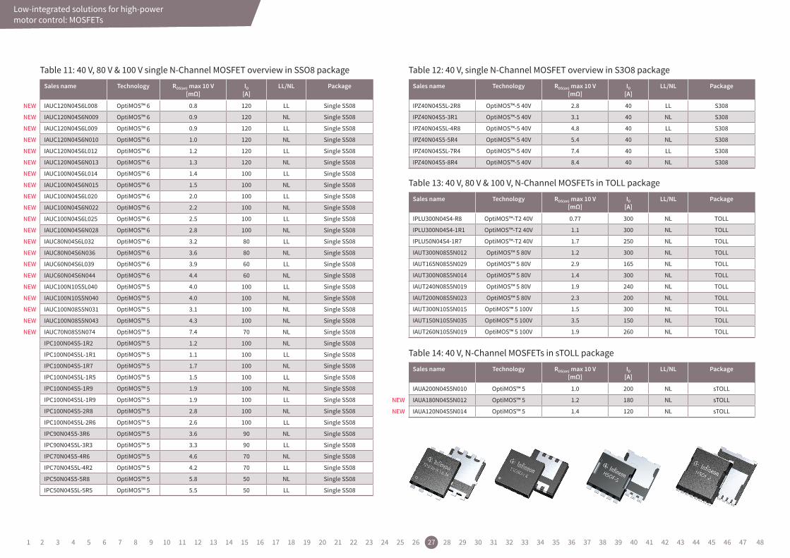
Table 11: 40 V, 80 V & 100 V single N-Channel MOSFET overview in SSO8 package
Table 13: 40 V, 80 V & 100 V, N-Channel MOSFETs in TOLL package
Table 14: 40 V, N-Channel MOSFETs in sTOLL package
Table 12: 40 V, single N-Channel MOSFET overview in S3O8 package
1 2 3 4 5 6 7 8 9 10 11 12 13 14 15 16 17 18 19 20 21 22 23 24 25 26 27 28 29 30 31 32 33 34 35 36 37 38 39 40 41 42 43 44 45 46 47 48
Low-integrated solutions for high-power motor control
Image 15: When to choose a DC/DC converter
Low-integrated solutions for high-power motor control: Power supply
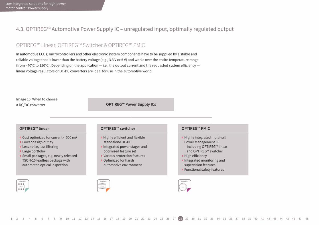
4.3. OPTIREG™ Automotive Power Supply IC – unregulated input, optimally regulated output
OPTIREG™ Linear, OPTIREG™ Switcher & OPTIREG™ PMICIn automotive ECUs, microcontrollers and other electronic system components have to be supplied by a stable and reliable voltage that is lower than the battery voltage (e.g., 3.3 V or 5 V) and works over the entire temperature range (from –40°C to 150°C). Depending on the application — i.e., the output current and the requested system efficiency — linear voltage regulators or DC-DC converters are ideal for use in the automotive world.
› Highly eicient and flexible standalone DC-DC› Integrated power stages and optimized feature set› Various protection features › Optimized for harsh automotive environment
› Highly integrated multi-rail Power Management IC – Including OPTIREG™ linear and OPTIREG™ switcher › High eiciency› Integrated monitoring and supervision features› Functional safety features
› Cost optimized for current < 500 mA› Lower design outlay› Less noise, less filtering› Large portfolio› Small packages, e.g. newly released TSON-10 leadless package with automated optical inspection
OPTIREG™ Power Supply ICs
OPTIREG™ linear OPTIREG™ switcher OPTIREG™ PMIC
1 2 3 4 5 6 7 8 9 10 11 12 13 14 15 16 17 18 19 20 21 22 23 24 25 26 27 28 29 30 31 32 33 34 35 36 37 38 39 40 41 42 43 44 45 46 47 48
Low-integrated solutions for high-power motor control
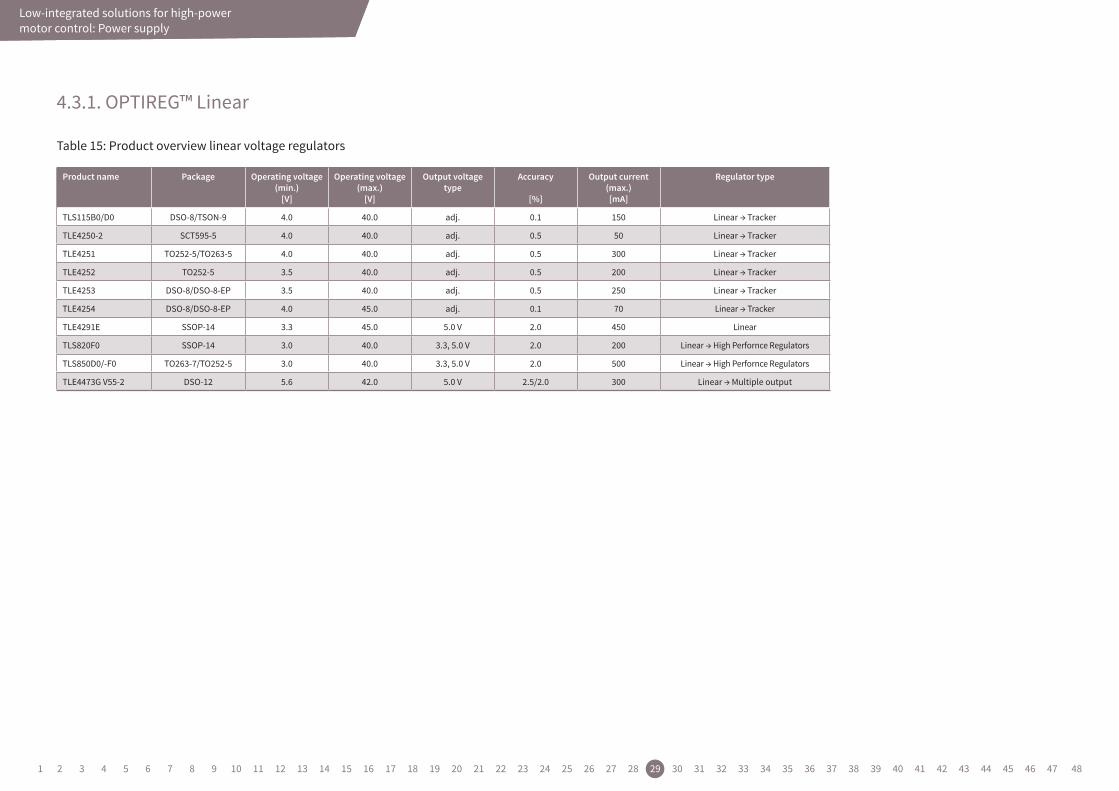
4.3.1. OPTIREG™ Linear
Table 15: Product overview linear voltage regulators
Low-integrated solutions for high-power motor control: Power supply
Product name Package Operating voltage(min.)
[V]
Operating voltage(max.)
[V]
Output voltagetype
Accuracy
[%]
Output current(max.)[mA]
Regulator type
TLS115B0/D0 DSO-8/TSON-9 4.0 40.0 adj. 0.1 150 Linear → Tracker
TLE4250-2 SCT595-5 4.0 40.0 adj. 0.5 50 Linear → Tracker
TLE4251 TO252-5/TO263-5 4.0 40.0 adj. 0.5 300 Linear → Tracker
TLE4252 TO252-5 3.5 40.0 adj. 0.5 200 Linear → Tracker
TLE4253 DSO-8/DSO-8-EP 3.5 40.0 adj. 0.5 250 Linear → Tracker
TLE4254 DSO-8/DSO-8-EP 4.0 45.0 adj. 0.1 70 Linear → Tracker
TLE4291E SSOP-14 3.3 45.0 5.0 V 2.0 450 Linear
TLS820F0 SSOP-14 3.0 40.0 3.3, 5.0 V 2.0 200 Linear → High Perfornce Regulators
TLS850D0/-F0 TO263-7/TO252-5 3.0 40.0 3.3, 5.0 V 2.0 500 Linear → High Perfornce Regulators
TLE4473G V55-2 DSO-12 5.6 42.0 5.0 V 2.5/2.0 300 Linear → Multiple output
1 2 3 4 5 6 7 8 9 10 11 12 13 14 15 16 17 18 19 20 21 22 23 24 25 26 27 28 29 30 31 32 33 34 35 36 37 38 39 40 41 42 43 44 45 46 47 48
Low-integrated solutions for high-power motor control
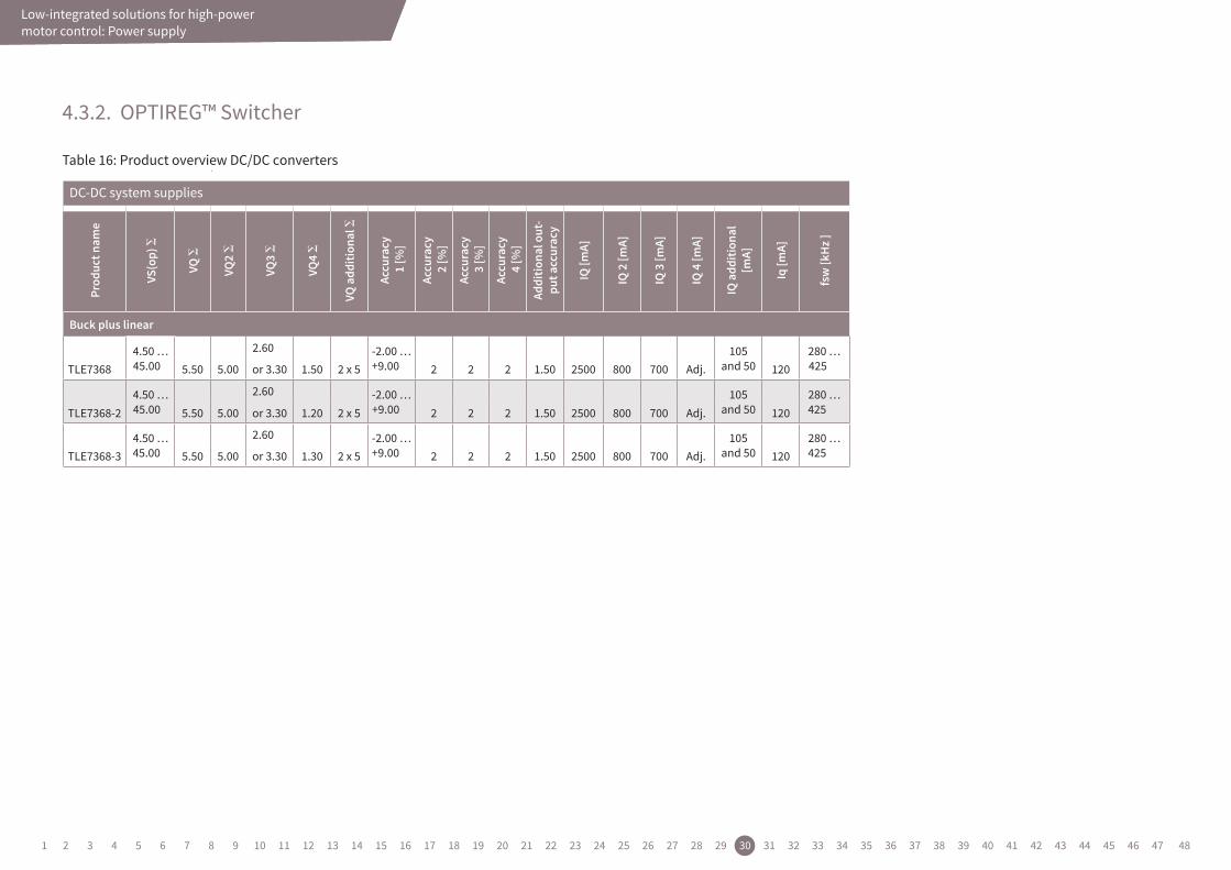
4.3.2. OPTIREG™ Switcher
Table 16: Product overview DC/DC converters
DC-DC system supplies
Prod
uctn
ame
VS(op)
VQ
VQ2
VQ3
VQ4
VQadd
ition
al
Accu
racy
1[%
]
Accu
racy
2[%
]
Accu
racy
3[%
]
Accu
racy
4[%
]
Additio
nalo
ut-
puta
ccurac
y
IQ[m
A]
IQ2[m
A]
IQ3[m
A]
IQ4[m
A]
IQadd
ition
al
[mA]
Iq[m
A]
fsw[k
Hz]
Buckpluslinear
4.50 … 45.00
2.60 -2.00 …+9.00
105 and 50
280 … 425TLE7368 5.50 5.00 or 3.30 1.50 2 x 5 2 2 2 1.50 2500 800 700 Adj. 120
4.50 … 45.00
2.60 -2.00 …+9.00
105 and 50
280 … 425TLE7368-2 5.50 5.00 or 3.30 1.20 2 x 5 2 2 2 1.50 2500 800 700 Adj. 120
4.50 … 45.00
2.60 -2.00 …+9.00
105 and 50
280 … 425TLE7368-3 5.50 5.00 or 3.30 1.30 2 x 5 2 2 2 1.50 2500 800 700 Adj. 120
Low-integrated solutions for high-power motor control
4.3.2. OPTIREG™ Switcher
Table 16: Product overview DC/DC converters
DC-DC system supplies
Prod
uctn
ame
VS(op)
VQ
VQ2
VQ3
VQ4
VQadd
ition
al
Accu
racy
1[%
]
Accu
racy
2[%
]
Accu
racy
3[%
]
Accu
racy
4[%
]
Additio
nalo
ut-
puta
ccurac
y
IQ[m
A]
IQ2[m
A]
IQ3[m
A]
IQ4[m
A]
IQadd
ition
al
[mA]
Iq[m
A]
fsw[k
Hz]
Buckpluslinear
4.50 … 45.00
2.60 -2.00 …+9.00
105 and 50
280 … 425TLE7368 5.50 5.00 or 3.30 1.50 2 x 5 2 2 2 1.50 2500 800 700 Adj. 120
4.50 … 45.00
2.60 -2.00 …+9.00
105 and 50
280 … 425TLE7368-2 5.50 5.00 or 3.30 1.20 2 x 5 2 2 2 1.50 2500 800 700 Adj. 120
4.50 … 45.00
2.60 -2.00 …+9.00
105 and 50
280 … 425TLE7368-3 5.50 5.00 or 3.30 1.30 2 x 5 2 2 2 1.50 2500 800 700 Adj. 120
Low-integrated solutions for high-power motor control: Power supply
1 2 3 4 5 6 7 8 9 10 11 12 13 14 15 16 17 18 19 20 21 22 23 24 25 26 27 28 29 30 31 32 33 34 35 36 37 38 39 40 41 42 43 44 45 46 47 48
Low-integrated solutions for high-power motor controlLow-integrated solutions for high-power motor control: Transceivers
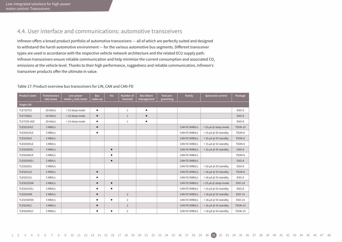
4.4. User interface and communications: automotive transceiversInfineon offers a broad product portfolio of automotive transceivers — all of which are perfectly suited and designed to withstand the harsh automotive environment — for the various automotive bus segments. Different transceiver types are used in accordance with the respective vehicle network architecture and the related ECU supply path. Infineon transceivers ensure reliable communication and help minimize the current consumption and associated CO2 emissions at the vehicle level. Thanks to their high performance, ruggedness and reliable communication, Infineon’s transceiver products offer the ultimate in value.
Table 17: Product overview bus transceivers for LIN, CAN and CAN-FD
Product name Transmissionrate (max)
Low-powermode Iq [mA] (max)
Bus wake-up
Vio Number ofchannels
Bus failuremanagement
Fast pro-gramming
Family Quiescent current Package
Single LIN
TLE7257SJ 20 kbit/s < 15 sleep mode l 1 l DSO-8
TLE7258SJ 20 kbit/s < 15 sleep mode l 1 l DSO-8
TLE7259-3GE 20 kbit/s < 10 sleep mode l 1 l DSO-8
TLE9252VLC 5 MBit/s l CAN FD 5MBit/s < 25 µA @ sleep mode TSON-14
TLE9251VLE 5 MBit/s l CAN FD 5MBit/s < 15 µA @ 5V standby TSON-8
TLE9250LE 5 MBit/s CAN FD 5MBit/s < 20 µA @ 5V standby TSON-8
TLE9250VLE 5 MBit/s CAN FD 5MBit/s < 15 µA @ 5V standby TSON-8
TLE9250VSJ 5 MBit/s l CAN FD 5MBit/s < 15 µA @ 5V standby DSO-8
TLE9250XLE 5 MBit/s l CAN FD 5MBit/s TSON-8
TLE9250XSJ 5 MBit/s l CAN FD 5MBit/s DSO-8
TLE9250SJ 5 MBit/s CAN FD 5MBit/s < 20 µA @ 5V standby DSO-8
TLE9251LE 5 MBit/s l CAN FD 5MBit/s < 18 µA @ 5V standby TSON-8
TLE9251SJ 5 MBit/s l CAN FD 5MBit/s < 18 µA @ 5V standby DSO-8
TLE9252VSK 5 MBit/s l l CAN FD 5MBit/s < 25 µA @ sleep mode DSO-14
TLE9251VSJ 5 MBit/s l l CAN FD 5MBit/s < 15 µA @ 5V standby DSO-8
TLE9254SK 5 MBit/s l 2 CAN FD 5MBit/s < 18 µA @ 5V standby DSO-14
TLE9254VSK 5 MBit/s l l 2 CAN FD 5MBit/s < 18 µA @ 5V standby DSO-14
TLE9254LC 5 MBit/s l 2 CAN FD 5MBit/s < 18 µA @ 5V standby TSON-14
TLE9254VLC 5 MBit/s l l 2 CAN FD 5MBit/s < 18 µA @ 5V standby TSON-14
1 2 3 4 5 6 7 8 9 10 11 12 13 14 15 16 17 18 19 20 21 22 23 24 25 26 27 28 29 30 31 32 33 34 35 36 37 38 39 40 41 42 43 44 45 46 47 48

Low-integrated solutions for high-power motor controlLow-integrated solutions for high-power motor control: Transceivers
Table 18: Product overview bus transceivers for LIN, CAN and CAN-FD (cont’d)
Product name Transmissionrate (max)
Low-powermode Iq [µA] (max)
Bus wake-up Wake-upinputs
Number ofchannels
Bus failuremanagement
CAN FD Package
High-speed CAN ISO 11898-2
TLE9250SJ 5 Mbit/s < 20 @ 5 V power save mode 1 l DSO-8
TLE9250LE 5 Mbit/s < 20 @ 5 V power save mode 1 l TSON-8
High-speed CAN ISO 11898-5
TLE6251-2G 1 Mbit/s < 30 sleep mode l l 1 l DSO-14
TLE6251-3G 1 Mbit/s < 30 sleep mode l l 1 l DSO-14
Table 19: Automotive FlexRay™, LIN transceivers
Product name Transmissionrate (max)
Low-powermode Iq [µA] (max)
Bus wake-up Additional Features Package
Automotive FlexRay™ Transceivers
TLE9222LC 10 MBit/s < 45 µA standby mode (Vcc & Vio) l STBN, ERRN, BGE, Vio TSON-14
TLE9222PX 10 MBit/s < 45 µA standby mode (Vcc & Vio) l STBN, ERRN, BGE, Vio TSSOP-14
TLE9221SX 10 MBit/s < 65 µA sleep mode l STBN, EN, WAKE, ERRN, BGE, INH, Vio, RxEN SSOP-16
Automotive LIN Transceivers
TLE7268SK 20 kBit/s < 20 µA sleep mode l Multiple channel, 2 x LIN trx, INH, EN DSO-14
TLE7257SJ 20 kBit/s < 10 µA sleep mode l INH, EN DSO-8
TLE7257LE 20 kBit/s < 10 µA sleep mode l INH, EN TSON-8
TLE8457DLE 20 kBit/s < 10 µA sleep mode l 3.3 V output VREG, EN, RESET TSON-8
TLE7258LE 20 kBit/s < 10 µA sleep mode l INH, EN TSON-8
TLE7268LC 20 kBit/s < 20 µA sleep mode l 2 x LIN trx, INH, EN TSON-14
TLE8457CSJ 20 kBit/s < 10 µA sleep mode l Multiple channel, 2 x LIN trx, INH, EN DSO-8
TLE8457CLE 20 kBit/s < 10 µA sleep mode l 5.0 V output VREG, EN, RESET TSON-8
TLE7258SJ 20 kBit/s < 10 µA sleep mode l INH, EN DSO-8
TLE7259-3LE 20 kBit/s < 10 µA sleep mode l INH, EN, WK TSON-8
TLE7259-3GE 20 kBit/s < 10 µA sleep mode l INH, EN, WK DSO-8
TLE7258D 20 kBit/s < 10 µA sleep mode l EN TSON-8
TLE8457DSJ 20 kBit/s < 10 µA sleep mode l 3.3 V output VREG, EN, RESET DSO-8
1 2 3 4 5 6 7 8 9 10 11 12 13 14 15 16 17 18 19 20 21 22 23 24 25 26 27 28 29 30 31 32 33 34 35 36 37 38 39 40 41 42 43 44 45 46 47 48
Low-integrated solutions for high-power motor controlLow-integrated solutions for high-power motor control: Sensors
4.5. XENSIV™ hall switches
Broadest energy saving portfolio of high precision Hall switches for automotive, industrial and consumer applications
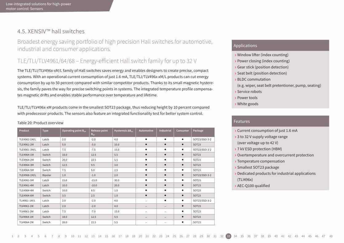
TLE/TLI/TLV4961/64/68 – Energy-efficient Hall switch family for up to 32 VThe TLE/TLI/TLV496x-xM/L family of Hall switches saves energy and enables designers to create precise, compact systems. With an operational current consumption of just 1.6 mA, TLE/TLI/TLV496x-xM/L products can cut energy consumption by up to 50 percent compared with similar competitor products. Thanks to its small magnetic hystere-sis, the family paves the way for precise switching points in systems. The integrated temperature profile compensa-tes magnetic drifts and enables stable performance over temperature and lifetime.
TLE/TLI/TLV496x-xM products come in the smallest SOT23 package, thus reducing height by 10 percent compared with predecessor products. The sensors also feature an integrated functionality test for better system control.
Product Type Operating point BOP Release point BRP
Hysteresis ΔBHY Automotive Industrial Consumer Package
TLE4961-1M/L Latch 2.0 -2.0 4.0 l l l SOT23/SSO-3-2
TLE4961-2M Latch 5.0 -5.0 10.0 l l l SOT23
TLE4961-3M/L Latch 7.5 -7.5 15.0 l l l SOT23/SSO-3-2
TLE4964-1M Switch 18.0 12.5 5.5 l l l SOT23
TLE4964-2M Switch 28.0 22.5 5.5 l l l SOT23
TLE4964-3M Switch 12.5 9.5 3.0 l l l SOT23
TLE4964-5M Switch 7.5 5.0 2.5 l l l SOT23
TLE4968-1M/L Bipolar 1.0 -1.0 2.0 l l l SOT23/SSO-3-2
TLE4961-5M Latch 15.0 -15.0 30.0 l l l SOT23
TLE4961-4M Latch 10.0 -10.0 20.0 l l l SOT23
TLE4964-4M Switch 10.0 8.5 1.5 l l l SOT23
TLE4964-6M Switch 3.5 2.5 1.0 l l l SOT23
TLI4961-1M/L Latch 2.0 -2.0 4.0 – l l SOT23/SSO-3-2
TLV4961-1M Latch 2.0 -2.0 4.0 – – l SOT23
TLV4961-3M Latch 7.5 -7.0 15.0 – – l SOT23
TLV4964-1M Switch 18.0 12.5 5.5 – – l SOT23
TLV4964-2M Switch 28.0 22.5 5.5 – – l SOT23
› Window lifter (index counting) › Power closing (index counting) › Gear stick (position detection) › Seat belt (position detection) › BLDC commutation (e.g. wiper, seat belt pretentioner, pump, seating) › Service robots › Power tools › White goods
› Current consumption of just 1.6 mA › 3 to 32 V supply voltage range (over voltage up to 42 V) › 7 kV ESD protection (HBM) › Overtemperature and overcurrent protection › Temperature compensation › Smallest SOT23 package › Dedicated products for industrial applications (TLI496x) › AEC-Q100 qualified
Applications
FeaturesTable 20: Product overview
1 2 3 4 5 6 7 8 9 10 11 12 13 14 15 16 17 18 19 20 21 22 23 24 25 26 27 28 29 30 31 32 33 34 35 36 37 38 39 40 41 42 43 44 45 46 47 48
Low-integrated solutions for high-power motor controlLow-integrated solutions for high-power motor control: Sensors
4.6. XENSIV™ angle sensors
Compact designs in small outline packages – at highest functional safety
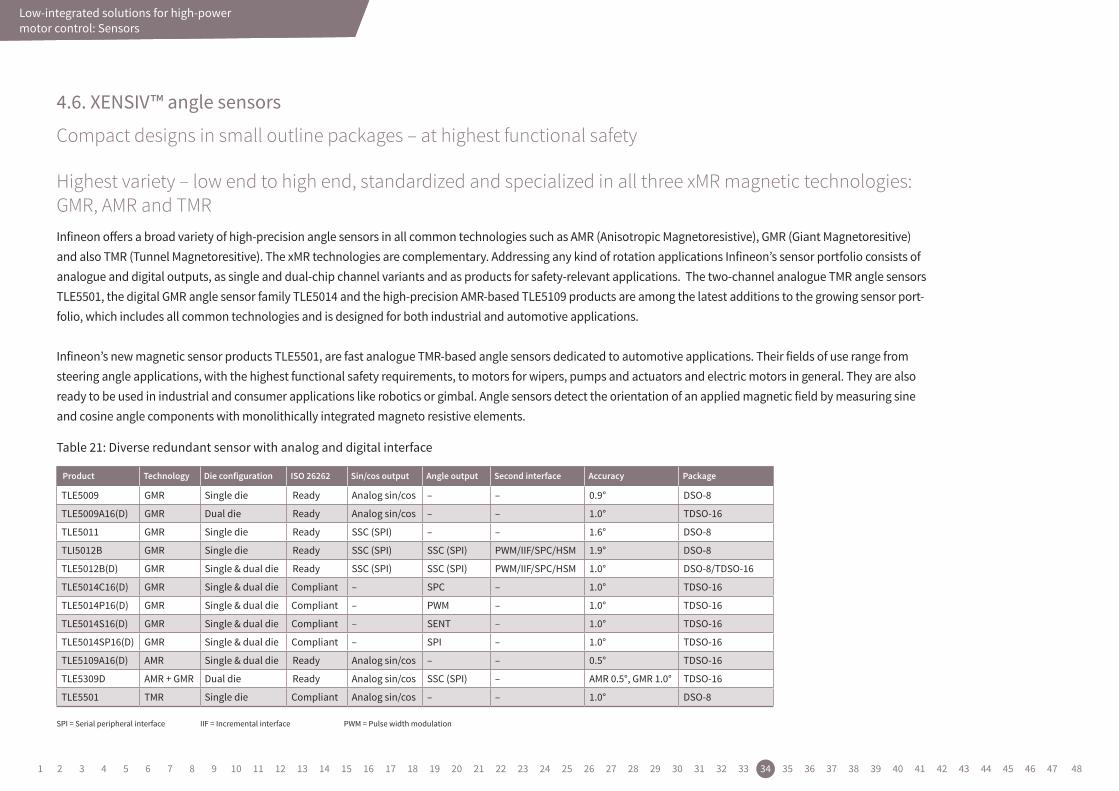
Highest variety – low end to high end, standardized and specialized in all three xMR magnetic technologies: GMR, AMR and TMRInfineon offers a broad variety of high-precision angle sensors in all common technologies such as AMR (Anisotropic Magnetoresistive), GMR (Giant Magnetoresitive) and also TMR (Tunnel Magnetoresitive). The xMR technologies are complementary. Addressing any kind of rotation applications Infineon’s sensor portfolio consists of analogue and digital outputs, as single and dual-chip channel variants and as products for safety-relevant applications. The two-channel analogue TMR angle sensors TLE5501, the digital GMR angle sensor family TLE5014 and the high-precision AMR-based TLE5109 products are among the latest additions to the growing sensor port-folio, which includes all common technologies and is designed for both industrial and automotive applications.
Infineon’s new magnetic sensor products TLE5501, are fast analogue TMR-based angle sensors dedicated to automotive applications. Their fields of use range from steering angle applications, with the highest functional safety requirements, to motors for wipers, pumps and actuators and electric motors in general. They are also ready to be used in industrial and consumer applications like robotics or gimbal. Angle sensors detect the orientation of an applied magnetic field by measuring sine and cosine angle components with monolithically integrated magneto resistive elements.
Product Technology Die configuration ISO 26262 Sin/cos output Angle output Second interface Accuracy Package
TLE5009 GMR Single die Ready Analog sin/cos – – 0.9° DSO-8
TLE5009A16(D) GMR Dual die Ready Analog sin/cos – – 1.0° TDSO-16
TLE5011 GMR Single die Ready SSC (SPI) – – 1.6° DSO-8
TLI5012B GMR Single die Ready SSC (SPI) SSC (SPI) PWM/IIF/SPC/HSM 1.9° DSO-8
TLE5012B(D) GMR Single & dual die Ready SSC (SPI) SSC (SPI) PWM/IIF/SPC/HSM 1.0° DSO-8/TDSO-16
TLE5014C16(D) GMR Single & dual die Compliant – SPC – 1.0° TDSO-16
TLE5014P16(D) GMR Single & dual die Compliant – PWM – 1.0° TDSO-16
TLE5014S16(D) GMR Single & dual die Compliant – SENT – 1.0° TDSO-16
TLE5014SP16(D) GMR Single & dual die Compliant – SPI – 1.0° TDSO-16
TLE5109A16(D) AMR Single & dual die Ready Analog sin/cos – – 0.5° TDSO-16
TLE5309D AMR + GMR Dual die Ready Analog sin/cos SSC (SPI) – AMR 0.5°, GMR 1.0° TDSO-16
TLE5501 TMR Single die Compliant Analog sin/cos – – 1.0° DSO-8
SPI = Serial peripheral interface IIF = Incremental interface PWM = Pulse width modulation
Table 21: Diverse redundant sensor with analog and digital interface
1 2 3 4 5 6 7 8 9 10 11 12 13 14 15 16 17 18 19 20 21 22 23 24 25 26 27 28 29 30 31 32 33 34 35 36 37 38 39 40 41 42 43 44 45 46 47 48
Low-integrated solutions for high-power motor controlLow-integrated solutions for high-power motor control: Sensors
4.7. XENSIV™ 3D magnetic sensors for automotive low-power applications
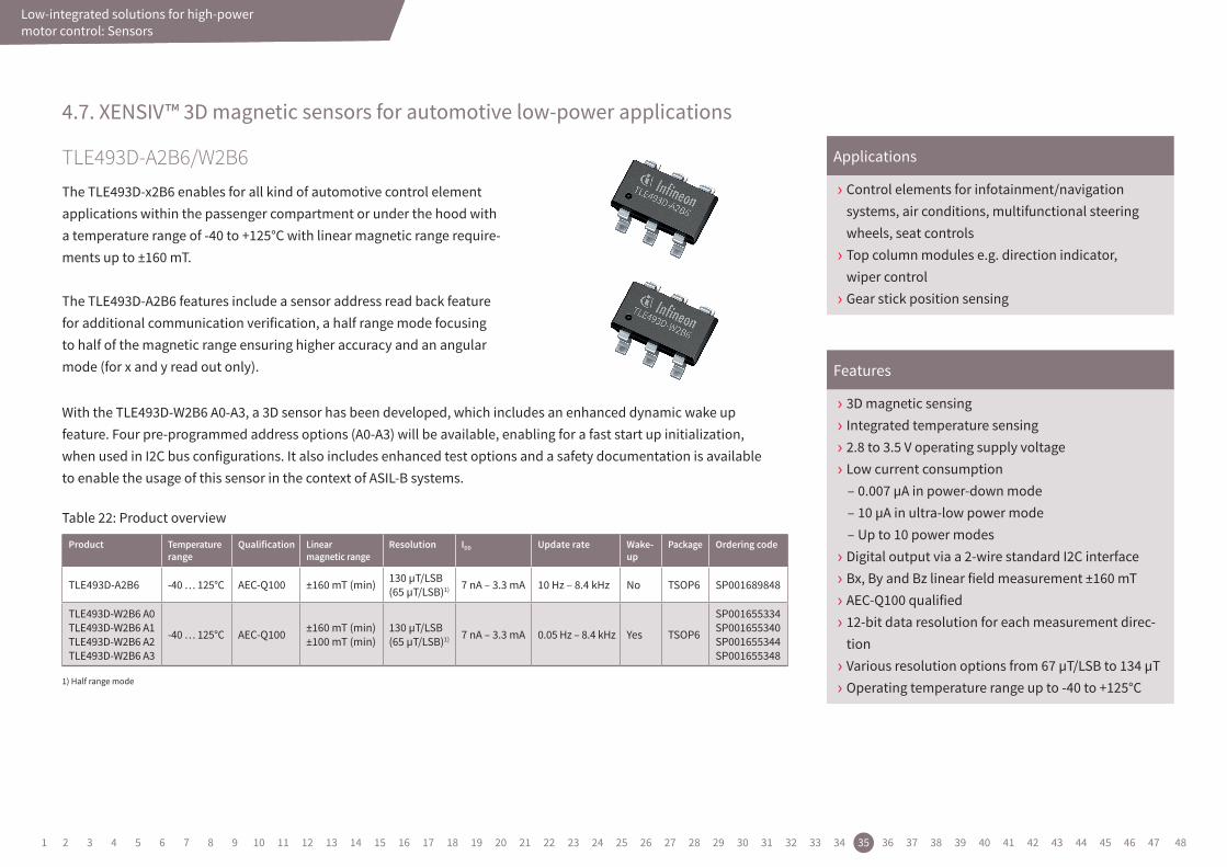
TLE493D-A2B6/W2B6The TLE493D-x2B6 enables for all kind of automotive control element applications within the passenger compartment or under the hood with a temperature range of -40 to +125°C with linear magnetic range require-ments up to ±160 mT.
The TLE493D-A2B6 features include a sensor address read back feature for additional communication verification, a half range mode focusing to half of the magnetic range ensuring higher accuracy and an angular mode (for x and y read out only).
With the TLE493D-W2B6 A0-A3, a 3D sensor has been developed, which includes an enhanced dynamic wake up feature. Four pre-programmed address options (A0-A3) will be available, enabling for a fast start up initialization, when used in I2C bus configurations. It also includes enhanced test options and a safety documentation is available to enable the usage of this sensor in the context of ASIL-B systems.
› Control elements for infotainment/navigation systems, air conditions, multifunctional steering wheels, seat controls › Top column modules e.g. direction indicator, wiper control › Gear stick position sensing
› 3D magnetic sensing › Integrated temperature sensing › 2.8 to 3.5 V operating supply voltage › Low current consumption
– 0.007 µA in power-down mode – 10 µA in ultra-low power mode – Up to 10 power modes
› Digital output via a 2-wire standard I2C interface › Bx, By and Bz linear field measurement ±160 mT › AEC-Q100 qualified › 12-bit data resolution for each measurement direc-tion › Various resolution options from 67 µT/LSB to 134 µT › Operating temperature range up to -40 to +125°C
Applications
Features
Product Temperature range
Qualification Linear magnetic range
Resolution IDD Update rate Wake- up
Package Ordering code
TLE493D-A2B6 -40 … 125°C AEC-Q100 ±160 mT (min) 130 µT/LSB (65 µT/LSB)1) 7 nA – 3.3 mA 10 Hz – 8.4 kHz No TSOP6 SP001689848
TLE493D-W2B6 A0TLE493D-W2B6 A1TLE493D-W2B6 A2TLE493D-W2B6 A3
-40 … 125°C AEC-Q100 ±160 mT (min) ±100 mT (min)
130 µT/LSB (65 µT/LSB)1) 7 nA – 3.3 mA 0.05 Hz – 8.4 kHz Yes TSOP6
SP001655334 SP001655340 SP001655344 SP001655348
1) Half range mode
Table 22: Product overview
1 2 3 4 5 6 7 8 9 10 11 12 13 14 15 16 17 18 19 20 21 22 23 24 25 26 27 28 29 30 31 32 33 34 35 36 37 38 39 40 41 42 43 44 45 46 47 48
Low-integrated solutions for high-power motor controlLow-integrated solutions for high-power motor control: Microcontroller
› Dedicated peripheral set : LIN, CAN, CAN-FD, SPI, FlexRay, Ethernet › Advanced timer unit for totally flexible PWM generation and hardware input capture › Redundant flexible 12-bit ADC › ISO 26262 conformance to support safety requirements up to ASIL–D › Innovative supply concept leads to best-in-class power consumption › Safety and development support by Infineon’s Preferred Design Houses, see list on www.infineon.com/pdh
Features4.8. AURIX™ for motor control applications
AURIX™ for high-performance, multicore and safety-demanding applications The AURIX™ 32-bit microcontroller family is based on the Infineon TriCore™ high-performance core concept and provides a highly scalable family from single core to multicore.
The AURIX™ family enables the highest integrated safe memory sizes (SRAM up to 6.9 MB and flash memory up to 16 MB) and all memory is protected by hardware Error Correction Code (ECC). The devices reach more than 600 DMIPS at clock rates of up to 6x 300 MHz and combine MCU and DSP instructions with an integrated FPU.
The integrated peripheral set is primarily targeted toward motor control and power conversion, providing high-performance ADCs, DS ADCs and a full set of diverse high-performance timers. This is one of the very few in the industry that is able to drive the upcoming three-level inverter topologies. Furthermore, the AURIX™ family supports the latest connectivity, such as Ethernet, CAN FD, FlexRay and multiple other high-speed interfaces.
1 2 3 4 5 6 7 8 9 10 11 12 13 14 15 16 17 18 19 20 21 22 23 24 25 26 27 28 29 30 31 32 33 34 35 36 37 38 39 40 41 42 43 44 45 46 47 48
Low-integrated solutions for high-power motor control
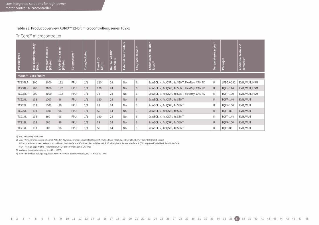
Table 23: Product overview AURIX™ 32-bit microcontrollers, series TC2xxPr
oduc
ttyp
e
Max
clock
freq
uenc
y[M
Hz]
Prog
ramm
emor
y[KBy
te]
SRAM
(inc
l.ca
che)
[KBy
te]
Co-proce
ssor
1
Cores/lock
step
Timed
I/OGPI/O
Numbe
rofA
DCcha
nnels
Extern
albus
interfac
e
CAN/
CAN-
FDnod
es
Commun
ication
interfac
es2
Tempe
raturera
nges
3
Pack
ages
Additio
nalfatures
/remarks
4
AURIX™—family
TC224L 133 1000 96 FPU 1/1 120 24 No 3 2x ASCLIN, 4x QSPI, 4x SENT K TQFP-144 EVR, WUT
TC223L 133 1000 96 FPU 1/1 78 24 No 3 2x ASCLIN, 4x QSPI, 4x SENT K TQFP-100 EVR, WUT
TC222L 133 1000 96 FPU 1/1 59 14 No 3 2x ASCLIN, 4x QSPI, 4x SENT K TQFP-80 EVR, WUT
TC214L 133 500 96 FPU 1/1 120 24 No 3 2x ASCLIN, 4x QSPI, 4x SENT K TQFP-144 EVR, WUT
TC213L 133 500 96 FPU 1/1 78 24 No 3 2x ASCLIN, 4x QSPI, 4x SENT K TQFP-100 EVR, WUT
TC212L 133 500 96 FPU 1/1 59 14 No 3 2x ASCLIN, 4x QSPI, 4x SENT K TQFP-80 EVR, WUT
1) FPU = Floating Point Unit2) ASCLIN = Asyn/Synchronous Local Interconnect Network, QSPI = Queued Serial Peripheral Interface, SENT = Single Edge Nibble Transmission3) Ambient temperature range: A = -40 ... 140 °C, B = 0 ... 70 °C, F = -40 ... 85 °C, H = -40 ... 110 °C, K = -40 ... 125 °C, L = -40 ... 150 °C, X = -40 ... 105 °C4) EVR = Embedded Voltage Regulator, WUT = Wake-Up Timer
TriCore™ microcontroller
Prod
uct t
ype
Max
clo
ck fr
eque
ncy
[MH
z]
Prog
ram
mem
ory
[KBy
te]
SRAM
(inc
l. ca
che)
[K
Byte
]
Co-p
roce
ssor
1)
Core
s/lo
ckst
ep
Tim
ed I/
O
GPI/O
Num
ber o
f ADC
ch
anne
ls
Exte
rnal
bus
inte
rfac
e
CAN/
CAN
FD n
odes
Com
mun
icat
ion
inte
r-fa
ces 2)
Tem
pera
ture
rang
es 3)
Pack
ages
Addi
tiona
l fea
ture
s/
rem
arks
4)
AURIX™ TC2xx family
TC237LP 200 2000 192 FPU 1/1 120 24 No 6 2x ASCLIN, 4x QSPI, 4x SENT, FlexRay, CAN FD K LFBGA-292 EVR, WUT, HSM
TC234LP 200 2000 192 FPU 1/1 120 24 No 6 2x ASCLIN, 4x QSPI, 4x SENT, FlexRay, CAN FD K TQFP-144 EVR, WUT, HSM
TC233LP 200 2000 192 FPU 1/1 78 24 No 6 2x ASCLIN, 4x QSPI, 4x SENT, FlexRay, CAN FD K TQFP-100 EVR, WUT, HSM
TC224L 133 1000 96 FPU 1/1 120 24 No 3 2x ASCLIN, 4x QSPI, 4x SENT K TQFP-144 EVR, WUT
TC223L 133 1000 96 FPU 1/1 78 24 No 3 2x ASCLIN, 4x QSPI, 4x SENT K TQFP-100 EVR, WUT
TC222L 133 1000 96 FPU 1/1 59 14 No 3 2x ASCLIN, 4x QSPI, 4x SENT K TQFP-80 EVR, WUT
TC214L 133 500 96 FPU 1/1 120 24 No 3 2x ASCLIN, 4x QSPI, 4x SENT K TQFP-144 EVR, WUT
TC213L 133 500 96 FPU 1/1 78 24 No 3 2x ASCLIN, 4x QSPI, 4x SENT K TQFP-100 EVR, WUT
TC212L 133 500 96 FPU 1/1 59 14 No 3 2x ASCLIN, 4x QSPI, 4x SENT K TQFP-80 EVR, WUT
1) FPU = Floating Point Unit2) ASC = Asynchronous Serial Channel, ASCLIN = Asyn/Synchronous Local Interconnect Network, HSSL = High Speed Serial Link, I2C = Inter-Integrated Circuit,
LIN = Local Interconnect Network, MLI = Micro Link Interface, MSC = Micro Second Channel, PSI5 = Peripheral Sensor Interface 5, QSPI = Queued Serial Peripheral Interface, SENT = Single Edge Nibble Transmission, SSC = Synchronous Serial Channel
3) Ambient temperature range: K = -40 ... 125°C,4) EVR = Embedded Voltage Regulator, HSM = Hardware Security Module, WUT = Wake-Up Timer
Low-integrated solutions for high-power motor control: Microcontroller
1 2 3 4 5 6 7 8 9 10 11 12 13 14 15 16 17 18 19 20 21 22 23 24 25 26 27 28 29 30 31 32 33 34 35 36 37 38 39 40 41 42 43 44 45 46 47 48
Low-integrated solutions for high-power motor control
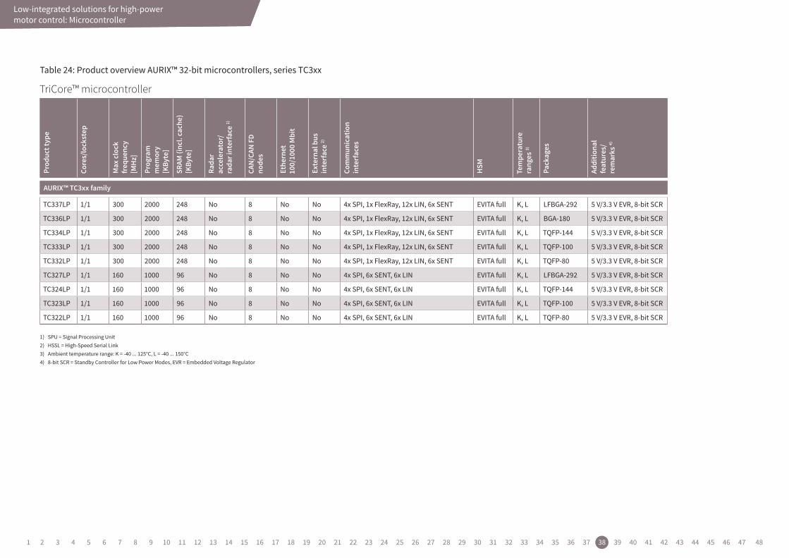
Table 24: Product overview AURIX™ 32-bit microcontrollers, series TC3xx
Product Table
Productname Packages ClockFrequencymax SRAM(incl.Cache) CANNodesA/DInputLines(incl.FADC)
AURIX™Family—TC21xL
SAK-TC214L-8F133F AB TQFP-144 133.0 MHz 56.0 kByte 3 24
SAK-TC213L-8F133F AB TQFP-100 133.0 MHz 56.0 kByte 3 24
SAK-TC213S-8F133F AB TQFP-100 133.0 MHz 56.0 kByte 3 24
SAK-TC212S-8F133F AB TQFP-80 133.0 MHz 56.0 kByte 3 14
SAK-TC212L-8F133F AB TQFP-80 133.0 MHz 56.0 kByte 3 14
SAK-TC214S-8F133F AB TQFP-144 133.0 MHz 56.0 kByte 3 24
AURIX™Family—TC22xL
SAK-TC224L-16F133F AB TQFP-144 133.0 MHz 96.0 kByte 3 24
SAK-TC223L-16F133F AB TQFP-100 133.0 MHz 96.0 kByte 3 24
SAK-TC222L-16F133F AB TQFP-80 133.0 MHz 96.0 kByte 3 14
SAK-TC224S-16F133F AB TQFP-144 133.0 MHz 96.0 kByte 3 24
SAK-TC223S-16F133F AB TQFP-100 133.0 MHz 96.0 kByte 3 24
SAK-TC222S-16F133F AB TQFP-80 133.0 MHz 96.0 kByte 3 14
TriCore™ microcontroller
Prod
uct t
ype
Core
s/lo
ckst
ep
Max
clo
ck
freq
uenc
y[M
Hz]
Prog
ram
m
emor
y
[KBy
te]
SRAM
(inc
l. ca
che)
[K
Byte
]
Rada
r ac
cele
rato
r/
rada
r int
erfa
ce 1)
CAN/
CAN
FD
node
s
Ethe
rnet
10
0/10
00 M
bit
Exte
rnal
bus
in
terf
ace
2)
Com
mun
icat
ion
in
terf
aces
HSM
Tem
pera
ture
ra
nges
3)
Pack
ages
Addi
tiona
l fe
atur
es/
rem
arks
4)
AURIX™ TC3xx family
TC337LP 1/1 300 2000 248 No 8 No No 4x SPI, 1x FlexRay, 12x LIN, 6x SENT EVITA full K, L LFBGA-292 5 V/3.3 V EVR, 8-bit SCR
TC336LP 1/1 300 2000 248 No 8 No No 4x SPI, 1x FlexRay, 12x LIN, 6x SENT EVITA full K, L BGA-180 5 V/3.3 V EVR, 8-bit SCR
TC334LP 1/1 300 2000 248 No 8 No No 4x SPI, 1x FlexRay, 12x LIN, 6x SENT EVITA full K, L TQFP-144 5 V/3.3 V EVR, 8-bit SCR
TC333LP 1/1 300 2000 248 No 8 No No 4x SPI, 1x FlexRay, 12x LIN, 6x SENT EVITA full K, L TQFP-100 5 V/3.3 V EVR, 8-bit SCR
TC332LP 1/1 300 2000 248 No 8 No No 4x SPI, 1x FlexRay, 12x LIN, 6x SENT EVITA full K, L TQFP-80 5 V/3.3 V EVR, 8-bit SCR
TC327LP 1/1 160 1000 96 No 8 No No 4x SPI, 6x SENT, 6x LIN EVITA full K, L LFBGA-292 5 V/3.3 V EVR, 8-bit SCR
TC324LP 1/1 160 1000 96 No 8 No No 4x SPI, 6x SENT, 6x LIN EVITA full K, L TQFP-144 5 V/3.3 V EVR, 8-bit SCR
TC323LP 1/1 160 1000 96 No 8 No No 4x SPI, 6x SENT, 6x LIN EVITA full K, L TQFP-100 5 V/3.3 V EVR, 8-bit SCR
TC322LP 1/1 160 1000 96 No 8 No No 4x SPI, 6x SENT, 6x LIN EVITA full K, L TQFP-80 5 V/3.3 V EVR, 8-bit SCR
1) SPU = Signal Processing Unit2) HSSL = High-Speed Serial Link3) Ambient temperature range: K = -40 ... 125°C, L = -40 ... 150°C4) 8-bit SCR = Standby Controller for Low Power Modes, EVR = Embedded Voltage Regulator
Low-integrated solutions for high-power motor control: Microcontroller
1 2 3 4 5 6 7 8 9 10 11 12 13 14 15 16 17 18 19 20 21 22 23 24 25 26 27 28 29 30 31 32 33 34 35 36 37 38 39 40 41 42 43 44 45 46 47 48
Evaluation boards
5. Evaluation boards
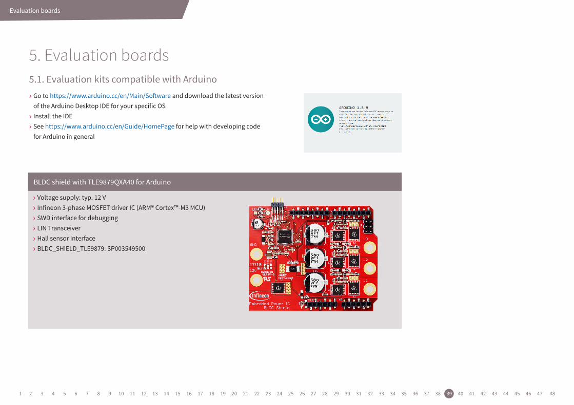
› Go to https://www.arduino.cc/en/Main/Software and download the latest version of the Arduino Desktop IDE for your specific OS › Install the IDE › See https://www.arduino.cc/en/Guide/HomePage for help with developing code for Arduino in general
› Voltage supply: typ. 12 V › Infineon 3-phase MOSFET driver IC (ARM® Cortex™-M3 MCU) › SWD interface for debugging › LIN Transceiver › Hall sensor interface › BLDC_SHIELD_TLE9879: SP003549500
BLDC shield with TLE9879QXA40 for Arduino
5.1. Evaluation kits compatible with Arduino
1 2 3 4 5 6 7 8 9 10 11 12 13 14 15 16 17 18 19 20 21 22 23 24 25 26 27 28 29 30 31 32 33 34 35 36 37 38 39 40 41 42 43 44 45 46 47 48
Evaluation boards
<No intersecting link>
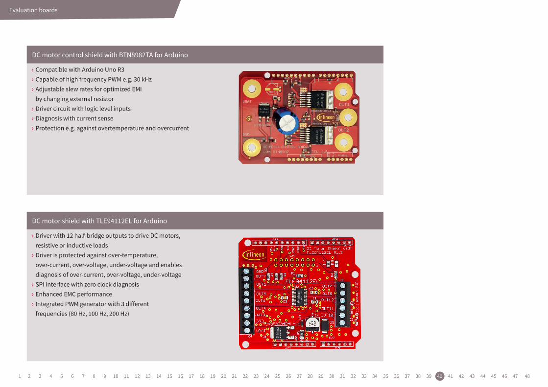
› Compatible with Arduino Uno R3 › Capable of high frequency PWM e.g. 30 kHz › Adjustable slew rates for optimized EMI by changing external resistor › Driver circuit with logic level inputs › Diagnosis with current sense › Protection e.g. against overtemperature and overcurrent
› Driver with 12 half-bridge outputs to drive DC motors, resistive or inductive loads › Driver is protected against over-temperature, over-current, over-voltage, under-voltage and enables diagnosis of over-current, over-voltage, under-voltage › SPI interface with zero clock diagnosis › Enhanced EMC performance › Integrated PWM generator with 3 different frequencies (80 Hz, 100 Hz, 200 Hz)
DC motor control shield with BTN8982TA for Arduino
DC motor shield with TLE94112EL for Arduino
1 2 3 4 5 6 7 8 9 10 11 12 13 14 15 16 17 18 19 20 21 22 23 24 25 26 27 28 29 30 31 32 33 34 35 36 37 38 39 40 41 42 43 44 45 46 47 48
Evaluation boards
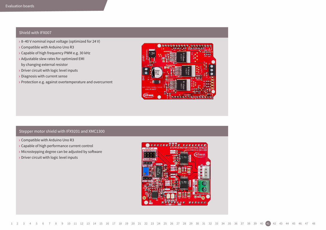
› 8–40 V nominal input voltage (optimized for 24 V) › Compatible with Arduino Uno R3 › Capable of high frequency PWM e.g. 30 kHz › Adjustable slew rates for optimized EMI by changing external resistor › Driver circuit with logic level inputs › Diagnosis with current sense › Protection e.g. against overtemperature and overcurrent
› Compatible with Arduino Uno R3 › Capable of high performance current control › Microstepping degree can be adjusted by software › Driver circuit with logic level inputs
Shield with IFX007
Stepper motor shield with IFX9201 and XMC1300
1 2 3 4 5 6 7 8 9 10 11 12 13 14 15 16 17 18 19 20 21 22 23 24 25 26 27 28 29 30 31 32 33 34 35 36 37 38 39 40 41 42 43 44 45 46 47 48

Infineon Toolbox
6. Infineon ToolboxInfineon tools in one place.The Infineon toolbox is a desktop application for easy discovery, download and installation of Infineon tools.
Please follow the link:https://www.infineon.com/toolbox
1 2 3 4 5 6 7 8 9 10 11 12 13 14 15 16 17 18 19 20 21 22 23 24 25 26 27 28 29 30 31 32 33 34 35 36 37 38 39 40 41 42 43 44 45 46 47 48
System Basis Chips (SBC) design in support & tool chain
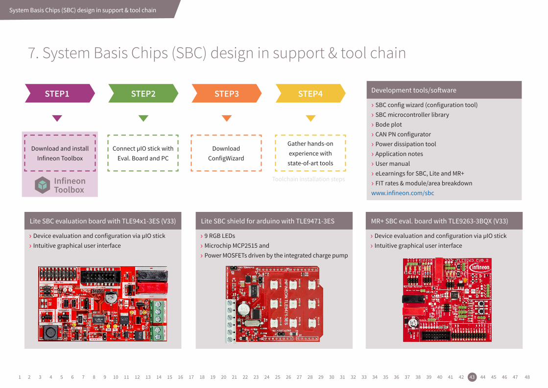
Connect µIO stick with Eval. Board and PC
Download and install Infineon Toolbox
DownloadConfigWizard
Gather hands-on experience with
state-of-art tools
STEP1 STEP2 STEP3 STEP4
7. System Basis Chips (SBC) design in support & tool chain
Toolchain installation steps
› SBC config wizard (configuration tool) › SBC microcontroller library › Bode plot › CAN PN configurator › Power dissipation tool › Application notes › User manual › eLearnings for SBC, Lite and MR+ › FIT rates & module/area breakdown
www.infineon.com/sbc
Development tools/software
› Device evaluation and configuration via µIO stick › Intuitive graphical user interface
› 9 RGB LEDs › Microchip MCP2515 and › Power MOSFETs driven by the integrated charge pump
› Device evaluation and configuration via µIO stick › Intuitive graphical user interface
Lite SBC evaluation board with TLE94x1-3ES (V33) Lite SBC shield for arduino with TLE9471-3ES MR+ SBC eval. board with TLE9263-3BQX (V33)
1 2 3 4 5 6 7 8 9 10 11 12 13 14 15 16 17 18 19 20 21 22 23 24 25 26 27 28 29 30 31 32 33 34 35 36 37 38 39 40 41 42 43 44 45 46 47 48
Embedded software development for Embedded Power ICs
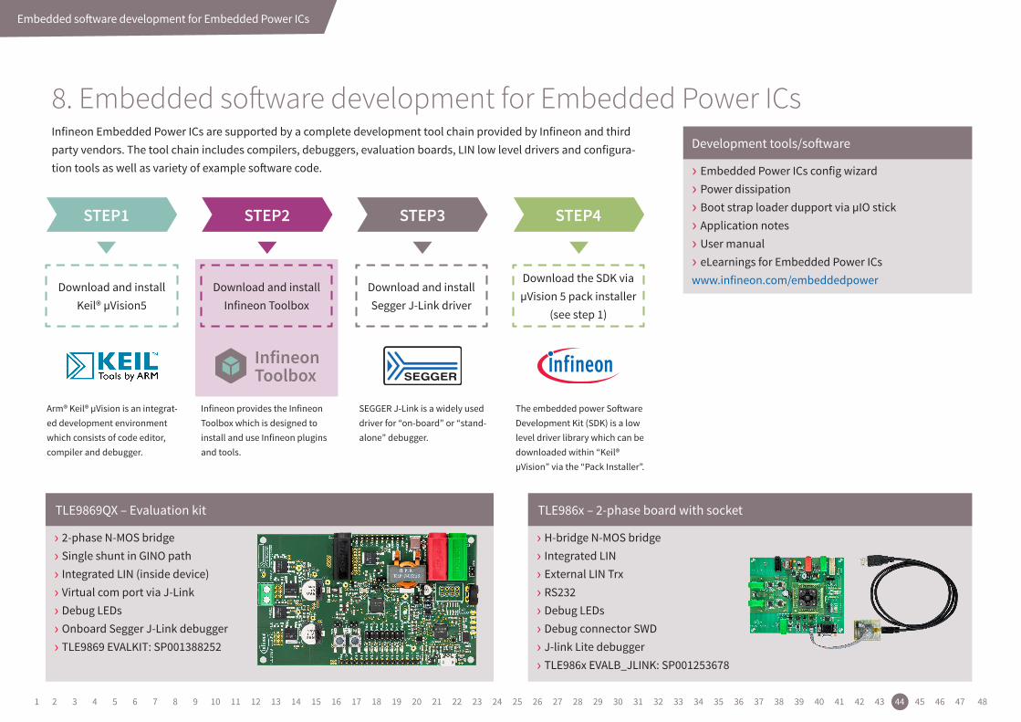
8. Embedded software development for Embedded Power ICsInfineon Embedded Power ICs are supported by a complete development tool chain provided by Infineon and third party vendors. The tool chain includes compilers, debuggers, evaluation boards, LIN low level drivers and configura-tion tools as well as variety of example software code.
Download and installKeil® µVision5
Arm® Keil® µVision is an integrat-ed development environment which consists of code editor, compiler and debugger.
Infineon provides the Infineon Toolbox which is designed to install and use Infineon plugins and tools.
SEGGER J-Link is a widely used driver for “on-board” or “stand-alone” debugger.
The embedded power Software Development Kit (SDK) is a low level driver library which can be downloaded within “Keil® µVision” via the “Pack Installer”.
Download and install Infineon Toolbox
Download and installSegger J-Link driver
Download the SDK via µVision 5 pack installer
(see step 1)
STEP1 STEP2 STEP3 STEP4
› Embedded Power ICs config wizard
› Power dissipation
› Boot strap loader dupport via µIO stick
› Application notes
› User manual
› eLearnings for Embedded Power ICswww.infineon.com/embeddedpower
Development tools/software
› 2-phase N-MOS bridge › Single shunt in GINO path › Integrated LIN (inside device) › Virtual com port via J-Link › Debug LEDs › Onboard Segger J-Link debugger › TLE9869 EVALKIT: SP001388252
› H-bridge N-MOS bridge › Integrated LIN › External LIN Trx › RS232 › Debug LEDs › Debug connector SWD › J-link Lite debugger › TLE986x EVALB_JLINK: SP001253678
TLE9869QX – Evaluation kit TLE986x – 2-phase board with socket
1 2 3 4 5 6 7 8 9 10 11 12 13 14 15 16 17 18 19 20 21 22 23 24 25 26 27 28 29 30 31 32 33 34 35 36 37 38 39 40 41 42 43 44 45 46 47 48
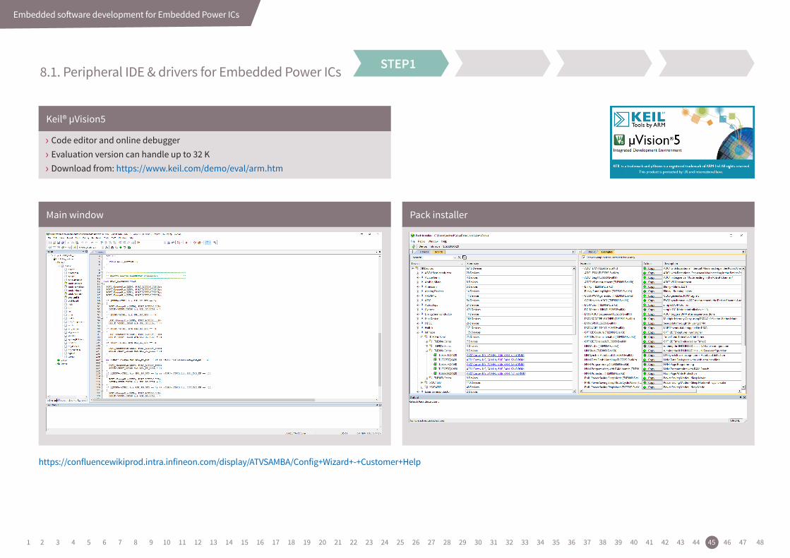
Embedded software development for Embedded Power ICs
STEP1
› Code editor and online debugger › Evaluation version can handle up to 32 K › Download from: https://www.keil.com/demo/eval/arm.htm
Keil® µVision5
Main window Pack installer
8.1. Peripheral IDE & drivers for Embedded Power ICs
https://confluencewikiprod.intra.infineon.com/display/ATVSAMBA/Config+Wizard+-+Customer+Help
1 2 3 4 5 6 7 8 9 10 11 12 13 14 15 16 17 18 19 20 21 22 23 24 25 26 27 28 29 30 31 32 33 34 35 36 37 38 39 40 41 42 43 44 45 46 47 48
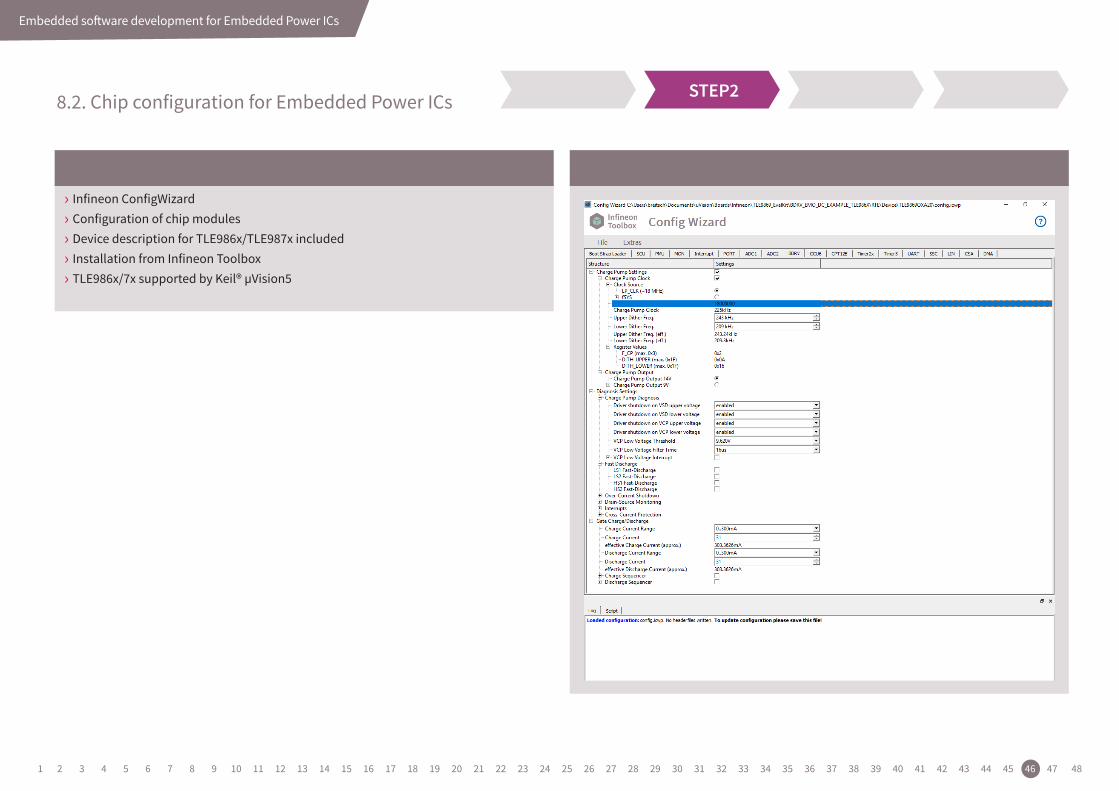
Embedded software development for Embedded Power ICs
STEP2
› Infineon ConfigWizard › Configuration of chip modules › Device description for TLE986x/TLE987x included › Installation from Infineon Toolbox › TLE986x/7x supported by Keil® µVision5
8.2. Chip configuration for Embedded Power ICs
1 2 3 4 5 6 7 8 9 10 11 12 13 14 15 16 17 18 19 20 21 22 23 24 25 26 27 28 29 30 31 32 33 34 35 36 37 38 39 40 41 42 43 44 45 46 47 48
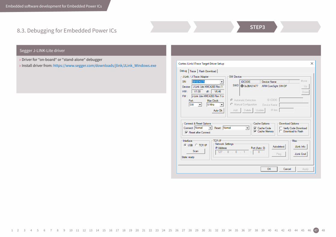
Embedded software development for Embedded Power ICs
STEP3
› Driver for “on-board“ or “stand-alone“ debugger › Install driver from: https://www.segger.com/downloads/jlink/JLink_Windows.exe
Segger J-LINK-Lite driver
8.3. Debugging for Embedded Power ICs
1 2 3 4 5 6 7 8 9 10 11 12 13 14 15 16 17 18 19 20 21 22 23 24 25 26 27 28 29 30 31 32 33 34 35 36 37 38 39 40 41 42 43 44 45 46 47 48
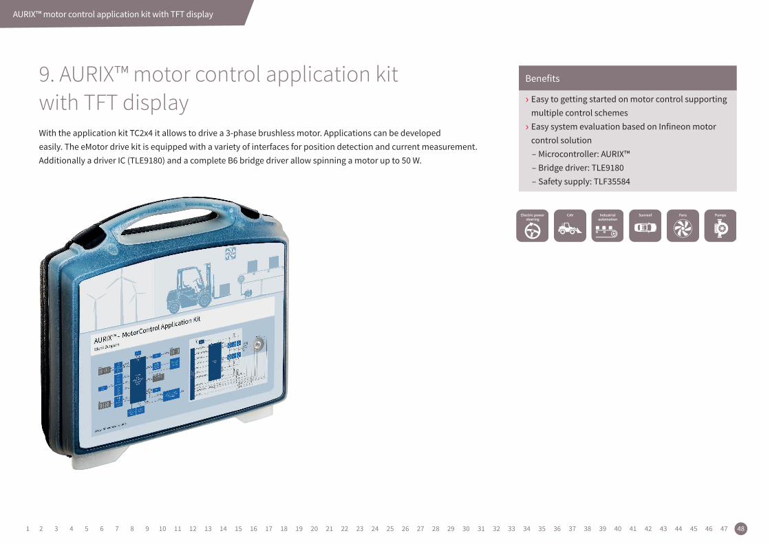
AURIX™ motor control application kit with TFT display
› Easy to getting started on motor control supporting multiple control schemes › Easy system evaluation based on Infineon motor control solution
– Microcontroller: AURIX™ – Bridge driver: TLE9180 – Safety supply: TLF35584
Benefits
With the application kit TC2x4 it allows to drive a 3-phase brushless motor. Applications can be developed easily. The eMotor drive kit is equipped with a variety of interfaces for position detection and current measurement. Additionally a driver IC (TLE9180) and a complete B6 bridge driver allow spinning a motor up to 50 W.
9. AURIX™ motor control application kit with TFT display
1 2 3 4 5 6 7 8 9 10 11 12 13 14 15 16 17 18 19 20 21 22 23 24 25 26 27 28 29 30 31 32 33 34 35 36 37 38 39 40 41 42 43 44 45 46 47 48
Service hotline
Infineon offers its toll-free 0800/4001 service hotline as one central number, available 24/7 in English, Mandarin and German.
› Germany .................... 0800 951 951 951 (German/English)
› China, mainland ....... 4001 200 951 (Mandarin/English)
› India .......................... 000 800 4402 951 (English)
› USA ............................ 1-866 951 9519 (English/German)
› Other countries ......... 00* 800 951 951 951 (English/German)
› Direct access ............. +49 89 234-0 (interconnection fee, German/English)
* Please note: Some countries may require you to dial a code other than “00” to access this international number. Please visit www.infineon.com/service for your country!
Where to buy
Infineon distribution partners and sales offices: www.infineon.com/WhereToBuy
Mobile product catalog
Mobile app for iOS and Android.
Published by Infineon Technologies AG81726 Munich, Germany
© 2019 Infineon Technologies AG. All rights reserved.
Order number: B000-H0000-X-X-7600 Date: 05 / 2019
Pleasenote!THIS DOCUMENT IS FOR INFORMATION PURPOSES ONLY AND ANY INFORMATION GIVEN HERE-IN SHALL IN NO EVENT BE REGARDED AS A WARRANTY, GUARANTEE OR DESCRIPTION OF ANY FUNCTIONALITY, CONDITIONS AND/OR QUALITY OF OUR PRODUCTS OR ANY SUITABILITY FOR A PARTICULAR PURPOSE. WITH REGARD TO THE TECHNICAL SPECIFICATIONS OF OUR PRODUCTS, WE KINDLY ASK YOU TO REFER TO THE RELEVANT PRODUCT DATA SHEETS PROVIDED BY US. OUR CUSTOMERS AND THEIR TECHNICAL DEPARTMENTS ARE REQUIRED TO EVALUATE THE SUITABILITY OF OUR PRODUCTS FOR THE INTENDED APPLICATION.
WE RESERVE THE RIGHT TO CHANGE THIS DOCUMENT AND/OR THE INFORMATION GIVEN HEREIN AT ANY TIME.
AdditionalinformationFor further information on technologies, our products, the application of our products, delivery terms and conditions and/or prices, please contact your nearest Infineon Technologies office (www.infineon.com).
WarningsDue to technical requirements, our products may contain dangerous substances. For information on the types in question, please contact your nearest Infineon Technologies office.
Except as otherwise explicitly approved by us in a written document signed by authorized repre-sentatives of Infineon Technologies, our products may not be used in any life- endangering applica-tions, including but not limited to medical, nuclear, military, life-critical or any other applications where a failure of the product or any consequences of the use thereof can result in personal injury.