Embed Size (px)
Citation preview

AutomotiveModal AnalysisAccelerometers; Dynamic Force Sensors; Modally Tuned®, ICP®, Impact Hammers;Electrodynamic Modal Shakers; and Accessories
WWW.PCB.COM
Automotive Sensors Division Toll-Free in USA 888-684-0014 716-684-0001 www.pcb.com
Automotive Modal Analysis
2 Automotive Sensors Division Toll-Free in USA 888-684-0014 716-684-0001 www.pcb.com
Test article exhibits time invariance & stationarity:
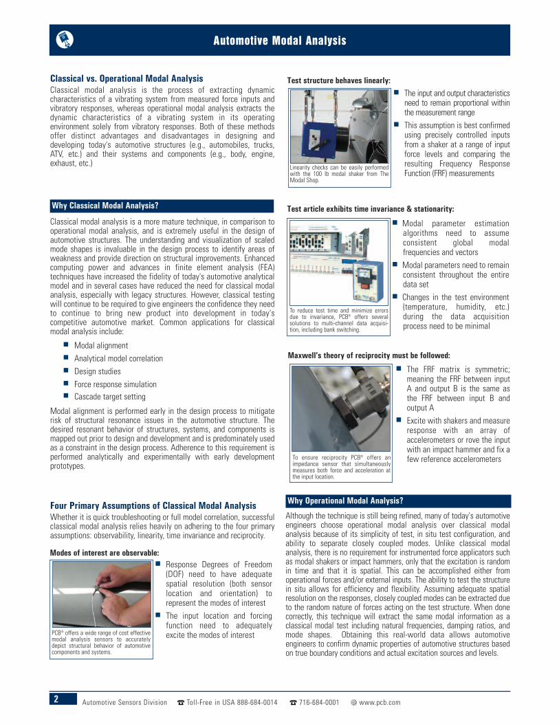
Modes of interest are observable:
Test structure behaves linearly:
Maxwell's theory of reciprocity must be followed:
PCB® offers a wide range of cost effectivemodal analysis sensors to accuratelydepict structural behavior of automotivecomponents and systems.
Linearity checks can be easily performedwith the 100 lb modal shaker from TheModal Shop.
To reduce test time and minimize errorsdue to invariance, PCB® offers severalsolutions to multi-channel data acquisi-tion, including bank switching.
To ensure reciprocity PCB® offers animpedance sensor that simultaneouslymeasures both force and acceleration atthe input location.
Response Degrees of Freedom(DOF) need to have adequatespatial resolution (both sensorlocation and orientation) torepresent the modes of interest
The input location and forcingfunction need to adequatelyexcite the modes of interest
Modal parameter estimationalgorithms need to assumeconsistent global modalfrequencies and vectors
Modal parameters need to remainconsistent throughout the entiredata set
Changes in the test environment(temperature, humidity, etc.)during the data acquisitionprocess need to be minimal
The FRF matrix is symmetric;meaning the FRF between inputA and output B is the same asthe FRF between input B andoutput A
Excite with shakers and measureresponse with an array ofaccelerometers or rove the inputwith an impact hammer and fix afew reference accelerometers
The input and output characteristicsneed to remain proportional withinthe measurement range
This assumption is best confirmedusing precisely controlled inputsfrom a shaker at a range of inputforce levels and comparing theresulting Frequency ResponseFunction (FRF) measurements
Classical vs. Operational Modal AnalysisClassical modal analysis is the process of extracting dynamiccharacteristics of a vibrating system from measured force inputs andvibratory responses, whereas operational modal analysis extracts thedynamic characteristics of a vibrating system in its operatingenvironment solely from vibratory responses. Both of these methodsoffer distinct advantages and disadvantages in designing anddeveloping today's automotive structures (e.g., automobiles, trucks,ATV, etc.) and their systems and components (e.g., body, engine,exhaust, etc.)
Classical modal analysis is a more mature technique, in comparison tooperational modal analysis, and is extremely useful in the design ofautomotive structures. The understanding and visualization of scaledmode shapes is invaluable in the design process to identify areas ofweakness and provide direction on structural improvements. Enhancedcomputing power and advances in finite element analysis (FEA)techniques have increased the fidelity of today's automotive analyticalmodel and in several cases have reduced the need for classical modalanalysis, especially with legacy structures. However, classical testingwill continue to be required to give engineers the confidence they needto continue to bring new product into development in today'scompetitive automotive market. Common applications for classicalmodal analysis include:
Modal alignment Analytical model correlation Design studies Force response simulation Cascade target setting
Modal alignment is performed early in the design process to mitigaterisk of structural resonance issues in the automotive structure. Thedesired resonant behavior of structures, systems, and components ismapped out prior to design and development and is predominately usedas a constraint in the design process. Adherence to this requirement isperformed analytically and experimentally with early developmentprototypes.
Four Primary Assumptions of Classical Modal AnalysisWhether it is quick troubleshooting or full model correlation, successfulclassical modal analysis relies heavily on adhering to the four primaryassumptions: observability, linearity, time invariance and reciprocity.
Although the technique is still being refined, many of today's automotiveengineers choose operational modal analysis over classical modalanalysis because of its simplicity of test, in situ test configuration, andability to separate closely coupled modes. Unlike classical modalanalysis, there is no requirement for instrumented force applicators suchas modal shakers or impact hammers, only that the excitation is randomin time and that it is spatial. This can be accomplished either fromoperational forces and/or external inputs. The ability to test the structurein situ allows for efficiency and flexibility. Assuming adequate spatialresolution on the responses, closely coupled modes can be extracted dueto the random nature of forces acting on the test structure. When donecorrectly, this technique will extract the same modal information as aclassical modal test including natural frequencies, damping ratios, andmode shapes. Obtaining this real-world data allows automotiveengineers to confirm dynamic properties of automotive structures basedon true boundary conditions and actual excitation sources and levels.
Why Operational Modal Analysis?
Why Classical Modal Analysis?
3Automotive Sensors Division Toll-Free in USA 888-684-0014 716-684-0001 www.pcb.com
Automotive Modal Analysis
General Purpose, ICP® Accelerometers for Automotive Modal AnalysisOverall, the optimal accelerometer for automotive modal analysis is one that has high sensitivity with excellent resolution, a wide frequency range andsmall mass. Trade-offs are usually made since a large sensor’s inertial mass is directly proportional to resolution and sensitivity and inversely proportionalto frequency range. For very small objects, like brake pads or rearview mirrors, a small, lightweight accelerometer with a wide frequency range ispreferred over a larger accelerometer with high sensitivity, in order to minimize errors due to mass loading a small structure. For larger structures, suchas body-in-white, a larger accelerometer with better resolution and higher sensitivity is optimal. While the choice of an accelerometer is similar betweena classical and operational modal analysis test, there is a significant contrast in the ambient and operating condition in which the measurement is made.An operational modal test is performed in a structure’s ambient environment which can be quite harsh, requiring hermetically sealed connectors and goodtemperature resistivity. The operating inputs can also be quite severe requiring the sensor to have good amplitude range and a robust construction.
PCB® offers a complete line of ICP® single axis and triaxial accelerometers for automotive modal analysis ranging from highly sensitive and lightweightsensors for low level inputs and mild environments to units with high ranges, hermetically sealed connectors, and rugged titanium construction for severeinputs and environments. With a variety of packages, mounting, and output cabling options, these sensors can accommodate virtually any automotivemodal analysis testing situation. Optional “TEDS” circuitry offers ‘smart sensing’ solutions for automating sensor performance bookkeeping and structurecoordinate mapping.
Response Output Measurements
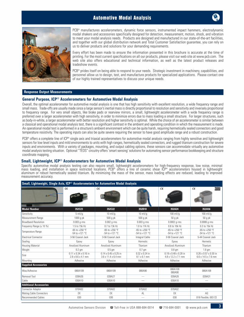
PCB® manufactures accelerometers, dynamic force sensors, instrumented impact hammers, electrodynamicmodal shakers and accessories specifically designed for detection, measurement, motion, shock, and vibrationto meet your modal analysis needs. Products are designed and manufactured in our state-of-the-art facilities,and together with our global distribution network and Total Customer Satisfaction guarantee, you can rely onus to deliver products and solutions for your demanding requirements.
Every effort has been made to ensure the information presented in this brochure is accurate at the time ofprinting. For the most current specifications on all our products, please visit our web site at www.pcb.com. Theweb site also offers educational and technical information, as well as the latest product releases andtradeshow events.
PCB® prides itself on being able to respond to your needs. Strategic investment in machinery, capabilities, andpersonnel allow us to design, test, and manufacture products for specialized applications. Please contact oneof our highly trained representatives to discuss your unique needs.
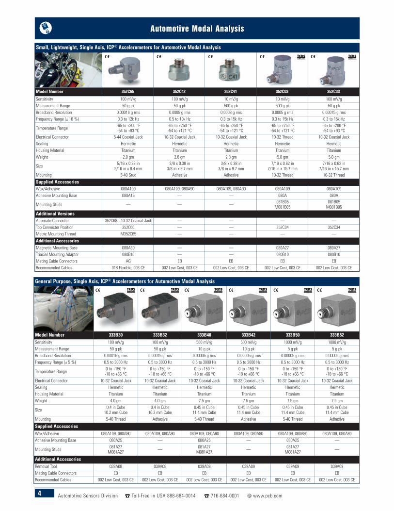
Small, Lightweight, Single Axis, ICP® Accelerometers for Automotive Modal Analysis
Model Number 352C23 352C22 352B10 352A24 352A56
Sensitivity 5 mV/g 10 mV/g 10 mV/g 100 mV/g 100 mV/gMeasurement Range 1000 g pk 500 g pk 500 g pk 50 g pk 50 g pkBroadband Resolution 0.003 g rms 0.002 g rms 0.003 g rms 0.0002 g rms 0.0006 g rmsFrequency Range (± 10 %) 1.5 to 15k Hz 0.7 to 13k Hz 1.0 to 17k Hz 0.8 to 10k Hz 0.3 to 15k Hz
Temperature Range -65 to +250 °F-54 to +121 °C
-65 to +250 °F-54 to +121 °C
-65 to +250 °F-54 to +121 °C
-65 to +250 °F-54 to +121 °C
-65 to +250 °F-54 to +121 °C
Electrical Connector 3-56 Coaxial Jack 3-56 Coaxial Jack Integral Cable 3-56 Coaxial Jack 5-44 Coaxial Jack
Sealing Epoxy Epoxy Hermetic Epoxy HermeticHousing Material Anodized Aluminum Anodized Aluminum Titanium Anodized Aluminum TitaniumWeight 0.2 gm 0.5 gm 0.7 gm 0.8 gm 1.8 gm
Size 0.11 x 0.34 x 0.16 in2.8 x 8.6 x 4.1 mm
0.14 x 0.45 x 0.25 in3.6 x 11.4 x 6.4 mm
0.32 x 0.24 in8.1 x 6.1 mm
0.19 x 0.48 x 0.28 in4.8 x 12.2 x 7.1 mm
0.26 x 0.57 x 0.30 in6.6 x 14.5 x 7.6 mm
Mounting Adhesive Adhesive Adhesive Adhesive Adhesive
Supplied Accessories
Wax/Adhesive 080A109 080A109 080A90 080A109080A90 080A109
Removal Tool 039A26 039A27 — 039A28 039A31Cable 030A10 030A10 — 030A10 —
Additional Accessories
Connector Adaptor 070A02 070A02 070A02 070A02 —Mating Cable Connectors EK EK AL EK AGRecommended Cables 030 030 — 030 018 Flexible, 003 CE
Small, Lightweight, ICP® Accelerometers for Automotive Modal AnalysisSpecific automotive modal analysis testing can also require small, lightweight accelerometers for high-frequency response, low noise, minimalmass loading, and installation in space restricted locations. PCB® offers a line of ceramic shear ICP® accelerometers housed in lightweightaluminum or robust hermetically sealed titanium. By minimizing the mass of the sensor, mass loading effects are reduced, leading to improvedmeasurement accuracy.
4 Automotive Sensors Division Toll-Free in USA 888-684-0014 716-684-0001 www.pcb.com
Automotive Modal Analysis
General Purpose, Single Axis, ICP® Accelerometers for Automotive Modal Analysis
Model Number 333B30 333B32 333B40 333B42 333B50 333B52Sensitivity 100 mV/g 100 mV/g 500 mV/g 500 mV/g 1000 mV/g 1000 mV/gMeasurement Range 50 g pk 50 g pk 10 g pk 10 g pk 5 g pk 5 g pkBroadband Resolution 0.00015 g rms 0.00015 g rms 0.00005 g rms 0.00005 g rms 0.00005 g rms 0.00005 g rmsFrequency Range (± 5 %) 0.5 to 3000 Hz 0.5 to 3000 Hz 0.5 to 3000 Hz 0.5 to 3000 Hz 0.5 to 3000 Hz 0.5 to 3000 Hz
Temperature Range 0 to +150 °F-18 to +66 °C
0 to +150 °F- 18 to +66 °C
0 to +150 °F-18 to +66 °C
0 to +150 °F-18 to +66 °C
0 to +150 °F-18 to +66 °C
0 to +150 °F-18 to +66 °C
Electrical Connector 10-32 Coaxial Jack 10-32 Coaxial Jack 10-32 Coaxial Jack 10-32 Coaxial Jack 10-32 Coaxial Jack 10-32 Coaxial JackSealing Hermetic Hermetic Hermetic Hermetic Hermetic HermeticHousing Material Titanium Titanium Titanium Titanium Titanium TitaniumWeight 4.0 gm 4.0 gm 7.5 gm 7.5 gm 7.5 gm 7.5 gm
Size 0.4 in Cube10.2 mm Cube
0.4 in Cube10.2 mm Cube
0.45 in Cube11.4 mm Cube
0.45 in Cube11.4 mm Cube
0.45 in Cube11.4 mm Cube
0.45 in Cube11.4 mm Cube
Mounting 5-40 Thread Adhesive 5-40 Thread Adhesive 5-40 Thread Adhesive
Supplied AccessoriesWax/Adhesive 080A109, 080A90 080A109, 080A90 080A109, 080A90 080A109, 080A90 080A109, 080A90 080A109, 080A90Adhesive Mounting Base 080A25 — 080A25 — 080A25 —
Mounting Studs 081A27M081A27 — 081A27
M081A27 — 081A27M081A27 —
Additional AccessoriesRemoval Tool 039A08 039A08 039A09 039A09 039A09 039A09Mating Cable Connectors EB EB EB EB EB EBRecommended Cables 002 Low Cost, 003 CE 002 Low Cost, 003 CE 002 Low Cost, 003 CE 002 Low Cost, 003 CE 002 Low Cost, 003 CE 002 Low Cost, 003 CE
Small, Lightweight, Single Axis, ICP® Accelerometers for Automotive Modal Analysis
Model Number 352C65 352C42 352C41 352C03 352C33
Sensitivity 100 mV/g 100 mV/g 10 mV/g 10 mV/g 100 mV/gMeasurement Range 50 g pk 50 g pk 500 g pk 500 g pk 50 g pkBroadband Resolution 0.00016 g rms 0.0005 g rms 0.0008 g rms 0.0005 g rms 0.00015 g rmsFrequency Range (± 10 %) 0.3 to 12k Hz 0.5 to 10k Hz 0.3 to 15k Hz 0.3 to 15k Hz 0.3 to 15k Hz
Temperature Range -65 to +200 °F-54 to +93 °C
-65 to +250 °F-54 to +121 °C
-65 to +250 °F-54 to +121 °C
-65 to +250 °F-54 to +121 °C
-65 to +200 °F-54 to +93 °C
Electrical Connector 5-44 Coaxial Jack 10-32 Coaxial Jack 10-32 Coaxial Jack 10-32 Thread 10-32 Coaxial JackSealing Hermetic Hermetic Hermetic Hermetic HermeticHousing Material Titanium Titanium Titanium Titanium TitaniumWeight 2.0 gm 2.8 gm 2.8 gm 5.8 gm 5.8 gm
Size 5/16 x 0.33 in5/16 in x 8.4 mm
3/8 x 0.38 in3/8 in x 9.7 mm
3/8 x 0.38 in3/8 in x 9.7 mm
7/16 x 0.62 in7/16 in x 15.7 mm
7/16 x 0.62 in7/16 in x 15.7 mm
Mounting 5-40 Stud Adhesive Adhesive 10-32 Thread 10-32 Thread
Supplied AccessoriesWax/Adhesive 080A109 080A109, 080A90 080A109, 080A90 080A109 080A109Adhesive Mounting Base 080A15 — — 080A 080A
Mounting Studs — — — 081B05M081B05
081B05M081B05
Additional VersionsAlternate Connector 352C68 - 10-32 Coaxial Jack — — — —Top Connector Position 352C66 — — 352C04 352C34Metric Mounting Thread M352C65 — — — —
Additional Accessories
Magnetic Mounting Base 080A30 — — 080A27 080A27Triaxial Mounting Adaptor 080B16 — — 080B10 080B10Mating Cable Connectors AG EB EB EB EBRecommended Cables 018 Flexible, 003 CE 002 Low Cost, 003 CE 002 Low Cost, 003 CE 002 Low Cost, 003 CE 002 Low Cost, 003 CE
5Automotive Sensors Division Toll-Free in USA 888-684-0014 716-684-0001 www.pcb.com
Automotive Modal Analysis
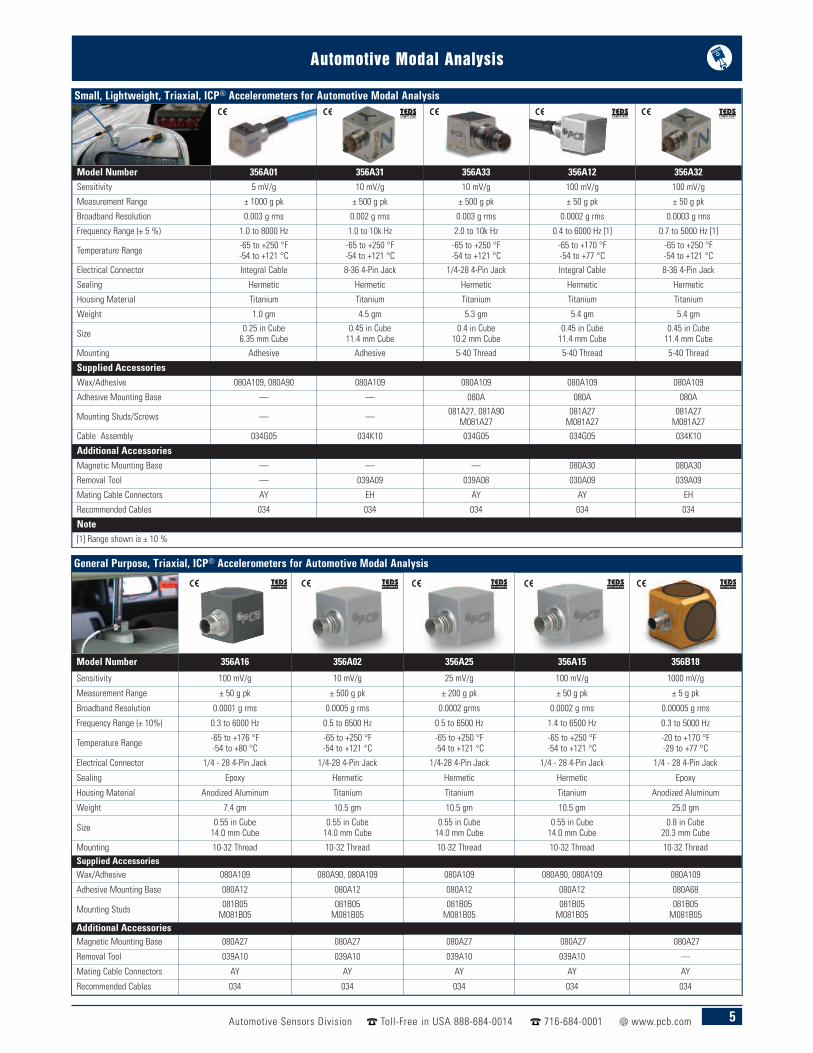
Small, Lightweight, Triaxial, ICP® Accelerometers for Automotive Modal Analysis
Model Number 356A01 356A31 356A33 356A12 356A32Sensitivity 5 mV/g 10 mV/g 10 mV/g 100 mV/g 100 mV/g
Measurement Range ± 1000 g pk ± 500 g pk ± 500 g pk ± 50 g pk ± 50 g pk
Broadband Resolution 0.003 g rms 0.002 g rms 0.003 g rms 0.0002 g rms 0.0003 g rms
Frequency Range (± 5 %) 1.0 to 8000 Hz 1.0 to 10k Hz 2.0 to 10k Hz 0.4 to 6000 Hz [1] 0.7 to 5000 Hz [1]
Temperature Range -65 to +250 °F-54 to +121 °C
-65 to +250 °F-54 to +121 °C
-65 to +250 °F-54 to +121 °C
-65 to +170 °F-54 to +77 °C
-65 to +250 °F-54 to +121 °C
Electrical Connector Integral Cable 8-36 4-Pin Jack 1/4-28 4-Pin Jack Integral Cable 8-36 4-Pin Jack
Sealing Hermetic Hermetic Hermetic Hermetic Hermetic
Housing Material Titanium Titanium Titanium Titanium Titanium
Weight 1.0 gm 4.5 gm 5.3 gm 5.4 gm 5.4 gm
Size 0.25 in Cube6.35 mm Cube
0.45 in Cube11.4 mm Cube
0.4 in Cube10.2 mm Cube
0.45 in Cube11.4 mm Cube
0.45 in Cube11.4 mm Cube
Mounting Adhesive Adhesive 5-40 Thread 5-40 Thread 5-40 Thread
Supplied AccessoriesWax/Adhesive 080A109, 080A90 080A109 080A109 080A109 080A109
Adhesive Mounting Base — — 080A 080A 080A
Mounting Studs/Screws — — 081A27, 081A90M081A27
081A27M081A27
081A27M081A27
Cable Assembly 034G05 034K10 034G05 034G05 034K10
Additional AccessoriesMagnetic Mounting Base — — — 080A30 080A30
Removal Tool — 039A09 039A08 030A09 039A09
Mating Cable Connectors AY EH AY AY EH
Recommended Cables 034 034 034 034 034
Note[1] Range shown is ± 10 %
General Purpose, Triaxial, ICP® Accelerometers for Automotive Modal Analysis
Model Number 356A16 356A02 356A25 356A15 356B18
Sensitivity 100 mV/g 10 mV/g 25 mV/g 100 mV/g 1000 mV/g
Measurement Range ± 50 g pk ± 500 g pk ± 200 g pk ± 50 g pk ± 5 g pk
Broadband Resolution 0.0001 g rms 0.0005 g rms 0.0002 grms 0.0002 g rms 0.00005 g rms
Frequency Range (± 10%) 0.3 to 6000 Hz 0.5 to 6500 Hz 0.5 to 6500 Hz 1.4 to 6500 Hz 0.3 to 5000 Hz
Temperature Range -65 to +176 °F-54 to +80 °C
-65 to +250 °F-54 to +121 °C
-65 to +250 °F-54 to +121 °C
-65 to +250 °F-54 to +121 °C
-20 to +170 °F-29 to +77 °C
Electrical Connector 1/4 - 28 4-Pin Jack 1/4-28 4-Pin Jack 1/4-28 4-Pin Jack 1/4 - 28 4-Pin Jack 1/4 - 28 4-Pin Jack
Sealing Epoxy Hermetic Hermetic Hermetic Epoxy
Housing Material Anodized Aluminum Titanium Titanium Titanium Anodized Aluminum
Weight 7.4 gm 10.5 gm 10.5 gm 10.5 gm 25.0 gm
Size 0.55 in Cube14.0 mm Cube
0.55 in Cube14.0 mm Cube
0.55 in Cube14.0 mm Cube
0.55 in Cube14.0 mm Cube
0.8 in Cube20.3 mm Cube
Mounting 10-32 Thread 10-32 Thread 10-32 Thread 10-32 Thread 10-32 ThreadSupplied AccessoriesWax/Adhesive 080A109 080A90, 080A109 080A109 080A90, 080A109 080A109
Adhesive Mounting Base 080A12 080A12 080A12 080A12 080A68
Mounting Studs 081B05M081B05
081B05M081B05
081B05M081B05
081B05M081B05
081B05M081B05
Additional AccessoriesMagnetic Mounting Base 080A27 080A27 080A27 080A27 080A27
Removal Tool 039A10 039A10 039A10 039A10 —
Mating Cable Connectors AY AY AY AY AY
Recommended Cables 034 034 034 034 034
6 Automotive Sensors Division Toll-Free in USA 888-684-0014 716-684-0001 www.pcb.com
Automotive Modal Analysis
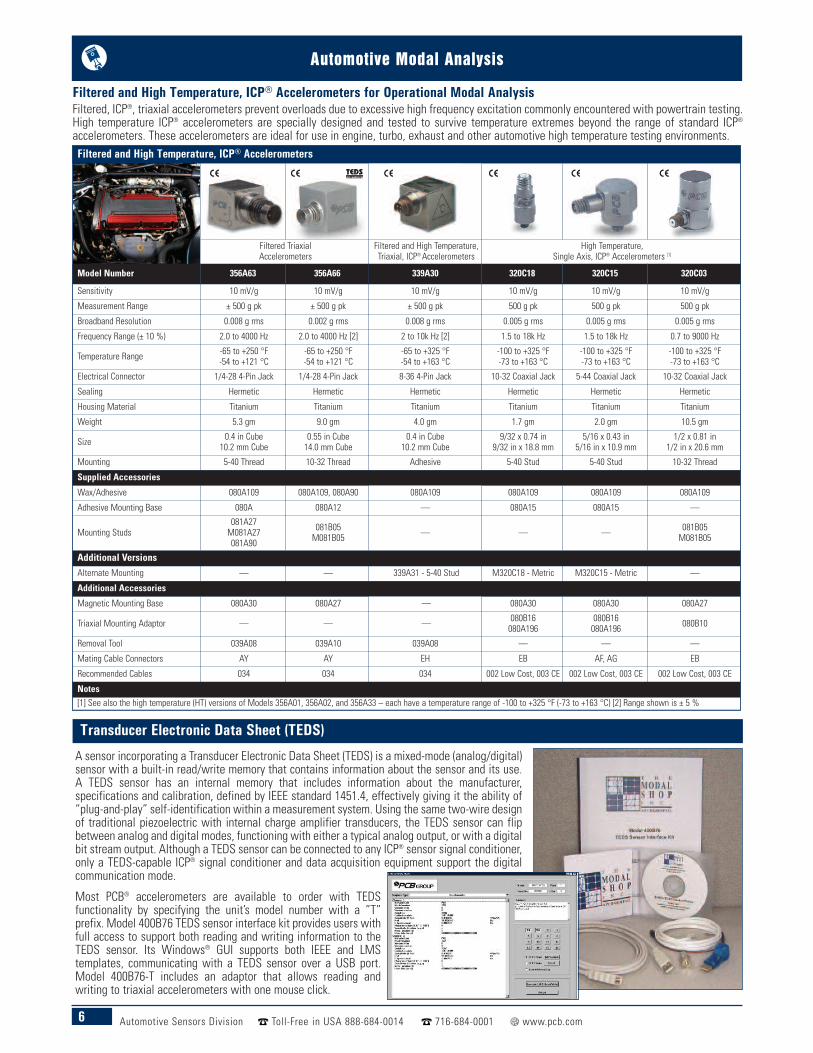
Filtered and High Temperature, ICP® Accelerometers for Operational Modal AnalysisFiltered, ICP®, triaxial accelerometers prevent overloads due to excessive high frequency excitation commonly encountered with powertrain testing.High temperature ICP® accelerometers are specially designed and tested to survive temperature extremes beyond the range of standard ICP®
accelerometers. These accelerometers are ideal for use in engine, turbo, exhaust and other automotive high temperature testing environments.Filtered and High Temperature, ICP® Accelerometers
Filtered TriaxialAccelerometers
Filtered and High Temperature,Triaxial, ICP®Accelerometers
High Temperature,Single Axis, ICP® Accelerometers [1]
Model Number 356A63 356A66 339A30 320C18 320C15 320C03
Sensitivity 10 mV/g 10 mV/g 10 mV/g 10 mV/g 10 mV/g 10 mV/g
Measurement Range ± 500 g pk ± 500 g pk ± 500 g pk 500 g pk 500 g pk 500 g pk
Broadband Resolution 0.008 g rms 0.002 g rms 0.008 g rms 0.005 g rms 0.005 g rms 0.005 g rms
Frequency Range (± 10 %) 2.0 to 4000 Hz 2.0 to 4000 Hz [2] 2 to 10k Hz [2] 1.5 to 18k Hz 1.5 to 18k Hz 0.7 to 9000 Hz
Temperature Range -65 to +250 °F-54 to +121 °C
-65 to +250 °F-54 to +121 °C
-65 to +325 °F-54 to +163 °C
-100 to +325 °F-73 to +163 °C
-100 to +325 °F-73 to +163 °C
-100 to +325 °F-73 to +163 °C
Electrical Connector 1/4-28 4-Pin Jack 1/4-28 4-Pin Jack 8-36 4-Pin Jack 10-32 Coaxial Jack 5-44 Coaxial Jack 10-32 Coaxial Jack
Sealing Hermetic Hermetic Hermetic Hermetic Hermetic Hermetic
Housing Material Titanium Titanium Titanium Titanium Titanium Titanium
Weight 5.3 gm 9.0 gm 4.0 gm 1.7 gm 2.0 gm 10.5 gm
Size 0.4 in Cube10.2 mm Cube
0.55 in Cube14.0 mm Cube
0.4 in Cube10.2 mm Cube
9/32 x 0.74 in9/32 in x 18.8 mm
5/16 x 0.43 in5/16 in x 10.9 mm
1/2 x 0.81 in1/2 in x 20.6 mm
Mounting 5-40 Thread 10-32 Thread Adhesive 5-40 Stud 5-40 Stud 10-32 Thread
Supplied Accessories
Wax/Adhesive 080A109 080A109, 080A90 080A109 080A109 080A109 080A109
Adhesive Mounting Base 080A 080A12 — 080A15 080A15 —
Mounting Studs081A27M081A27081A90
081B05M081B05 — — — 081B05
M081B05
Additional VersionsAlternate Mounting — — 339A31 - 5-40 Stud M320C18 - Metric M320C15 - Metric —
Additional Accessories
Magnetic Mounting Base 080A30 080A27 — 080A30 080A30 080A27
Triaxial Mounting Adaptor — — — 080B16080A196
080B16080A196 080B10
Removal Tool 039A08 039A10 039A08 — — —
Mating Cable Connectors AY AY EH EB AF, AG EB
Recommended Cables 034 034 034 002 Low Cost, 003 CE 002 Low Cost, 003 CE 002 Low Cost, 003 CE
Notes[1] See also the high temperature (HT) versions of Models 356A01, 356A02, and 356A33 – each have a temperature range of -100 to +325 °F (-73 to +163 °C) [2] Range shown is ± 5 %
Transducer Electronic Data Sheet (TEDS)
A sensor incorporating a Transducer Electronic Data Sheet (TEDS) is a mixed-mode (analog/digital)sensor with a built-in read/write memory that contains information about the sensor and its use.A TEDS sensor has an internal memory that includes information about the manufacturer,specifications and calibration, defined by IEEE standard 1451.4, effectively giving it the ability of“plug-and-play” self-identification within a measurement system. Using the same two-wire designof traditional piezoelectric with internal charge amplifier transducers, the TEDS sensor can flipbetween analog and digital modes, functioning with either a typical analog output, or with a digitalbit stream output. Although a TEDS sensor can be connected to any ICP® sensor signal conditioner,only a TEDS-capable ICP® signal conditioner and data acquisition equipment support the digitalcommunication mode.
Most PCB® accelerometers are available to order with TEDSfunctionality by specifying the unit’s model number with a ”T”prefix. Model 400B76 TEDS sensor interface kit provides users withfull access to support both reading and writing information to theTEDS sensor. Its Windows® GUI supports both IEEE and LMStemplates, communicating with a TEDS sensor over a USB port.Model 400B76-T includes an adaptor that allows reading andwriting to triaxial accelerometers with one mouse click.
7Automotive Sensors Division Toll-Free in USA 888-684-0014 716-684-0001 www.pcb.com
Automotive Modal Analysis
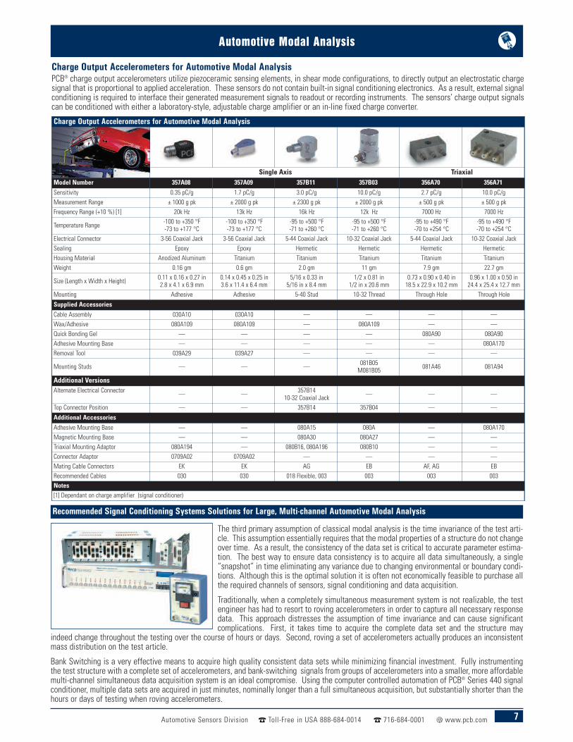
Recommended Signal Conditioning Systems Solutions for Large, Multi-channel Automotive Modal Analysis
The third primary assumption of classical modal analysis is the time invariance of the test arti-cle. This assumption essentially requires that the modal properties of a structure do not changeover time. As a result, the consistency of the data set is critical to accurate parameter estima-tion. The best way to ensure data consistency is to acquire all data simultaneously, a single“snapshot” in time eliminating any variance due to changing environmental or boundary condi-tions. Although this is the optimal solution it is often not economically feasible to purchase allthe required channels of sensors, signal conditioning and data acquisition.
Traditionally, when a completely simultaneous measurement system is not realizable, the testengineer has had to resort to roving accelerometers in order to capture all necessary responsedata. This approach distresses the assumption of time invariance and can cause significantcomplications. First, it takes time to acquire the complete data set and the structure may
indeed change throughout the testing over the course of hours or days. Second, roving a set of accelerometers actually produces an inconsistentmass distribution on the test article.
Bank Switching is a very effective means to acquire high quality consistent data sets while minimizing financial investment. Fully instrumentingthe test structure with a complete set of accelerometers, and bank-switching signals from groups of accelerometers into a smaller, more affordablemulti-channel simultaneous data acquisition system is an ideal compromise. Using the computer controlled automation of PCB® Series 440 signalconditioner, multiple data sets are acquired in just minutes, nominally longer than a full simultaneous acquisition, but substantially shorter than thehours or days of testing when roving accelerometers.
Charge Output Accelerometers for Automotive Modal AnalysisPCB® charge output accelerometers utilize piezoceramic sensing elements, in shear mode configurations, to directly output an electrostatic chargesignal that is proportional to applied acceleration. These sensors do not contain built-in signal conditioning electronics. As a result, external signalconditioning is required to interface their generated measurement signals to readout or recording instruments. The sensors’ charge output signalscan be conditioned with either a laboratory-style, adjustable charge amplifier or an in-line fixed charge converter.
Charge Output Accelerometers for Automotive Modal Analysis
Single Axis TriaxialModel Number 357A08 357A09 357B11 357B03 356A70 356A71
Sensitivity 0.35 pC/g 1.7 pC/g 3.0 pC/g 10.0 pC/g 2.7 pC/g 10.0 pC/gMeasurement Range ± 1000 g pk ± 2000 g pk ± 2300 g pk ± 2000 g pk ± 500 g pk ± 500 g pkFrequency Range (+10 %) [1] 20k Hz 13k Hz 16k Hz 12k Hz 7000 Hz 7000 Hz
Temperature Range -100 to +350 °F-73 to +177 °C
-100 to +350 °F-73 to +177 °C
-95 to +500 °F-71 to +260 °C
-95 to +500 °F-71 to +260 °C
-95 to +490 °F-70 to +254 °C
-95 to +490 °F-70 to +254 °C
Electrical Connector 3-56 Coaxial Jack 3-56 Coaxial Jack 5-44 Coaxial Jack 10-32 Coaxial Jack 5-44 Coaxial Jack 10-32 Coaxial JackSealing Epoxy Epoxy Hermetic Hermetic Hermetic HermeticHousing Material Anodized Aluminum Titanium Titanium Titanium Titanium TitaniumWeight 0.16 gm 0.6 gm 2.0 gm 11 gm 7.9 gm 22.7 gm
Size (Length x Width x Height) 0.11 x 0.16 x 0.27 in2.8 x 4.1 x 6.9 mm
0.14 x 0.45 x 0.25 in3.6 x 11.4 x 6.4 mm
5/16 x 0.33 in5/16 in x 8.4 mm
1/2 x 0.81 in1/2 in x 20.6 mm
0.73 x 0.90 x 0.40 in18.5 x 22.9 x 10.2 mm
0.96 x 1.00 x 0.50 in24.4 x 25.4 x 12.7 mm
Mounting Adhesive Adhesive 5-40 Stud 10-32 Thread Through Hole Through Hole
Supplied Accessories
Cable Assembly 030A10 030A10 — — — —Wax/Adhesive 080A109 080A109 — 080A109 — —Quick Bonding Gel — — — — 080A90 080A90Adhesive Mounting Base — — — — — 080A170Removal Tool 039A29 039A27 — — — —
Mounting Studs — — — 081B05M081B05 081A46 081A94
Additional VersionsAlternate Electrical Connector — — 357B14
10-32 Coaxial Jack — — —
Top Connector Position — — 357B14 357B04 — —
Additional Accessories
Adhesive Mounting Base — — 080A15 080A — 080A170Magnetic Mounting Base — — 080A30 080A27 — —Triaxial Mounting Adaptor 080A194 — 080B16, 080A196 080B10 — —Connector Adaptor 0709A02 0709A02 — — — —Mating Cable Connectors EK EK AG EB AF, AG EBRecommended Cables 030 030 018 Flexible, 003 003 003 003Notes[1] Dependant on charge amplifier (signal conditioner)
8 Automotive Sensors Division Toll-Free in USA 888-684-0014 716-684-0001 www.pcb.com
Automotive Modal Analysis
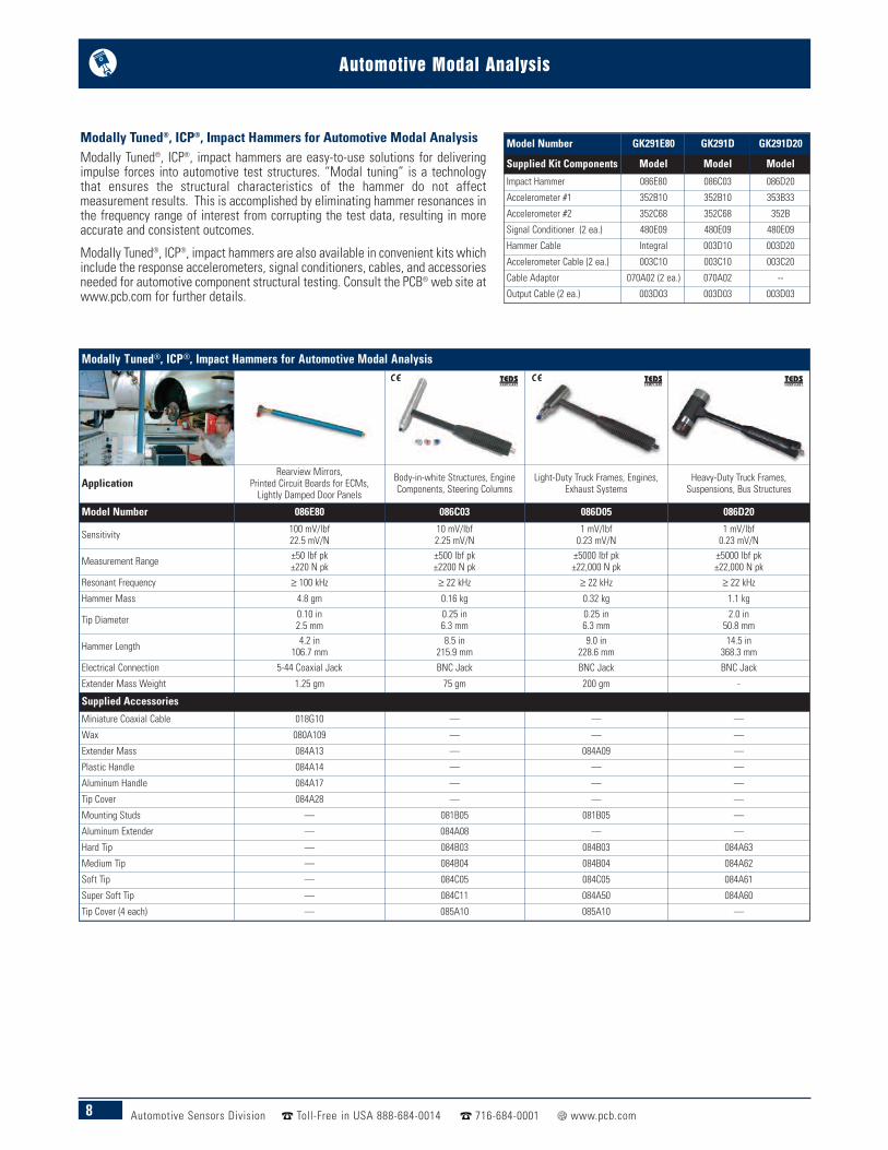
Modally Tuned®, ICP®, Impact Hammers for Automotive Modal AnalysisModally Tuned®, ICP®, impact hammers are easy-to-use solutions for deliveringimpulse forces into automotive test structures. “Modal tuning” is a technologythat ensures the structural characteristics of the hammer do not affectmeasurement results. This is accomplished by eliminating hammer resonances inthe frequency range of interest from corrupting the test data, resulting in moreaccurate and consistent outcomes.
Modally Tuned®, ICP®, impact hammers are also available in convenient kits whichinclude the response accelerometers, signal conditioners, cables, and accessoriesneeded for automotive component structural testing. Consult the PCB® web site atwww.pcb.com for further details.
Model Number GK291E80 GK291D GK291D20
Supplied Kit Components Model Model Model
Impact Hammer 086E80 086C03 086D20
Accelerometer #1 352B10 352B10 353B33
Accelerometer #2 352C68 352C68 352B
Signal Conditioner (2 ea.) 480E09 480E09 480E09
Hammer Cable Integral 003D10 003D20
Accelerometer Cable (2 ea.) 003C10 003C10 003C20
Cable Adaptor 070A02 (2 ea.) 070A02 --
Output Cable (2 ea.) 003D03 003D03 003D03
Modally Tuned®, ICP®, Impact Hammers for Automotive Modal Analysis
ApplicationRearview Mirrors,
Printed Circuit Boards for ECMs,Lightly Damped Door Panels
Body-in-white Structures, EngineComponents, Steering Columns
Light-Duty Truck Frames, Engines,Exhaust Systems
Heavy-Duty Truck Frames,Suspensions, Bus Structures
Model Number 086E80 086C03 086D05 086D20
Sensitivity 100 mV/lbf22.5 mV/N
10 mV/lbf2.25 mV/N
1 mV/lbf0.23 mV/N
1 mV/lbf0.23 mV/N
Measurement Range ±50 lbf pk±220 N pk
±500 lbf pk±2200 N pk
±5000 lbf pk±22,000 N pk
±5000 lbf pk±22,000 N pk
Resonant Frequency ≥ 100 kHz ≥ 22 kHz ≥ 22 kHz ≥ 22 kHz
Hammer Mass 4.8 gm 0.16 kg 0.32 kg 1.1 kg
Tip Diameter 0.10 in2.5 mm
0.25 in6.3 mm
0.25 in6.3 mm
2.0 in50.8 mm
Hammer Length 4.2 in106.7 mm
8.5 in215.9 mm
9.0 in228.6 mm
14.5 in368.3 mm
Electrical Connection 5-44 Coaxial Jack BNC Jack BNC Jack BNC Jack
Extender Mass Weight 1.25 gm 75 gm 200 gm -
Supplied Accessories
Miniature Coaxial Cable 018G10 — — —
Wax 080A109 — — —
Extender Mass 084A13 — 084A09 —
Plastic Handle 084A14 — — —
Aluminum Handle 084A17 — — —
Tip Cover 084A28 — — —
Mounting Studs — 081B05 081B05 —
Aluminum Extender — 084A08 — —
Hard Tip — 084B03 084B03 084A63
Medium Tip — 084B04 084B04 084A62
Soft Tip — 084C05 084C05 084A61
Super Soft Tip — 084C11 084A50 084A60
Tip Cover (4 each) — 085A10 085A10 —
9Automotive Sensors Division Toll-Free in USA 888-684-0014 716-684-0001 www.pcb.com
Automotive Modal Analysis
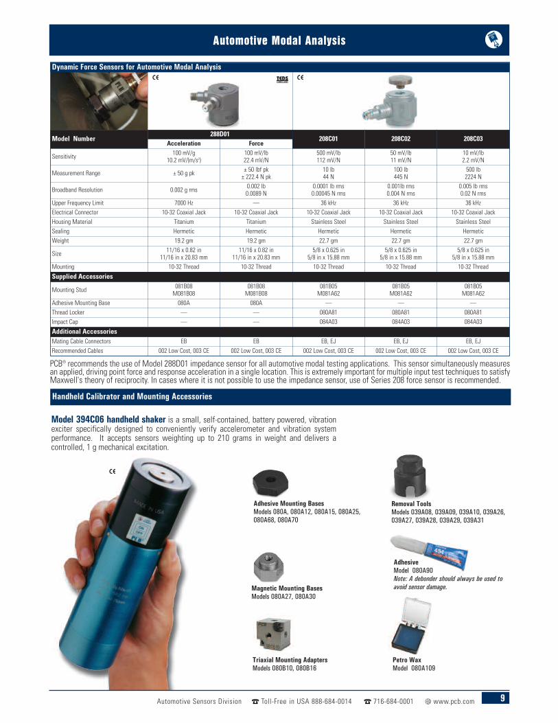
PCB® recommends the use of Model 288D01 impedance sensor for all automotive modal testing applications. This sensor simultaneously measuresan applied, driving point force and response acceleration in a single location. This is extremely important for multiple input test techniques to satisfyMaxwell's theory of reciprocity. In cases where it is not possible to use the impedance sensor, use of Series 208 force sensor is recommended.
Dynamic Force Sensors for Automotive Modal Analysis
Model Number288D01
208C01 208C02 208C03Acceleration Force
Sensitivity 100 mV/g10.2 mV/(m/s2)
100 mV/lb22.4 mV/N
500 mV/lb112 mV/N
50 mV/lb11 mV/N
10 mV/lb2.2 mV/N
Measurement Range ± 50 g pk ± 50 lbf pk± 222.4 N pk
10 lb44 N
100 lb445 N
500 lb2224 N
Broadband Resolution 0.002 g rms 0.002 lb0.0089 N
0.0001 lb rms0.00045 N rms
0.001lb rms0.004 N rms
0.005 lb rms0.02 N rms
Upper Frequency Limit 7000 Hz — 36 kHz 36 kHz 36 kHzElectrical Connector 10-32 Coaxial Jack 10-32 Coaxial Jack 10-32 Coaxial Jack 10-32 Coaxial Jack 10-32 Coaxial JackHousing Material Titanium Titanium Stainless Steel Stainless Steel Stainless SteelSealing Hermetic Hermetic Hermetic Hermetic HermeticWeight 19.2 gm 19.2 gm 22.7 gm 22.7 gm 22.7 gm
Size 11/16 x 0.82 in11/16 in x 20.83 mm
11/16 x 0.82 in11/16 in x 20.83 mm
5/8 x 0.625 in5/8 in x 15.88 mm
5/8 x 0.625 in5/8 in x 15.88 mm
5/8 x 0.625 in5/8 in x 15.88 mm
Mounting 10-32 Thread 10-32 Thread 10-32 Thread 10-32 Thread 10-32 Thread
Supplied Accessories
Mounting Stud 081B08M081B08
081B08M081B08
081B05M081A62
081B05M081A62
081B05M081A62
Adhesive Mounting Base 080A 080A — — —Thread Locker — — 080A81 080A81 080A81Impact Cap — — 084A03 084A03 084A03
Additional AccessoriesMating Cable Connectors EB EB EB, EJ EB, EJ EB, EJRecommended Cables 002 Low Cost, 003 CE 002 Low Cost, 003 CE 002 Low Cost, 003 CE 002 Low Cost, 003 CE 002 Low Cost, 003 CE
AdhesiveModel 080A90Note: A debonder should always be used toavoid sensor damage.
Removal ToolsModels 039A08, 039A09, 039A10, 039A26,039A27, 039A28, 039A29, 039A31
Petro WaxModel 080A109
Adhesive Mounting BasesModels 080A, 080A12, 080A15, 080A25,080A68, 080A70
Handheld Calibrator and Mounting Accessories
Model 394C06 handheld shaker is a small, self-contained, battery powered, vibrationexciter specifically designed to conveniently verify accelerometer and vibration systemperformance. It accepts sensors weighting up to 210 grams in weight and delivers acontrolled, 1 g mechanical excitation.
Magnetic Mounting BasesModels 080A27, 080A30
Triaxial Mounting AdaptersModels 080B10, 080B16
10 Automotive Sensors Division Toll-Free in USA 888-684-0014 716-684-0001 www.pcb.com
Automotive Modal Analysis
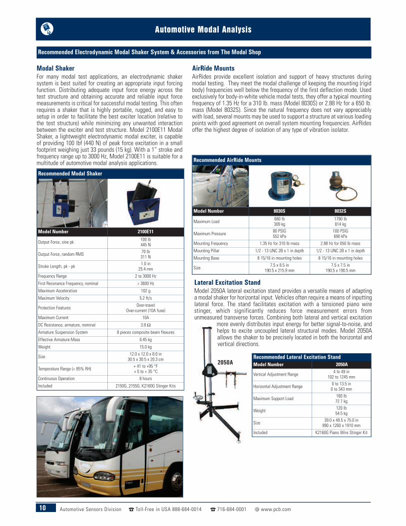
Lateral Excitation StandModel 2050A lateral excitation stand provides a versatile means of adaptinga modal shaker for horizontal input. Vehicles often require a means of inputtinglateral force. The stand facilitates excitation with a tensioned piano wirestinger, which significantly reduces force measurement errors fromunmeasured transverse forces. Combining both lateral and vertical excitation
more evenly distributes input energy for better signal-to-noise, andhelps to excite uncoupled lateral structural modes. Model 2050Aallows the shaker to be precisely located in both the horizontal andvertical directions.
Recommended Electrodynamic Modal Shaker System & Accessories from The Modal Shop
2050A
Recommended Modal Shaker
Model Number 2100E11
Output Force, sine pk 100 lb445 N
Output Force, random RMS 70 lb311 N
Stroke Length, pk - pk 1.0 in25.4 mm
Frequency Range 2 to 3000 Hz
First Resonance Frequency, nominal > 3600 Hz
Maximum Acceleration 102 g
Maximum Velocity 5.2 ft/s
Protection Features Over-travelOver-current (10A fuse)
Maximum Current 10A
DC Resistance, armature, nominal 3.8 ΩArmature Suspension System 8 pieces composite beam flexures
Effective Armature Mass 0.45 kg
Weight 15.0 kg
Size 12.0 x 12.0 x 8.0 in30.5 x 30.5 x 20.3 cm
Temperature Range (< 85% RH) + 41 to +95 °F+ 5 to + 35 °C
Continuous Operation 8 hours
Included 2150G, 2155G, K2160G Stinger Kits
Recommended AirRide Mounts
Model Number 8030S 8032S
Maximum Load 680 lb309 kg
1790 lb814 kg
Maximum Pressure 80 PSIG552 kPa
100 PSIG690 kPa
Mounting Frequency 1.35 Hz for 310 lb mass 2.88 Hz for 650 lb mass
Mounting Pillar 1/2 - 13 UNC 2B x 1 in depth 1/2 - 13 UNC 2B x 1 in depth
Mounting Base 8 15/16 in mounting holes 8 15/16 in mounting holes
Size 7.5 x 8.5 in190.5 x 215.9 mm
7.5 x 7.5 in190.5 x 190.5 mm
Recommended Lateral Excitation StandModel Number 2050A
Vertical Adjustment Range 4 to 49 in102 to 1245 mm
Horizontal Adjustment Range 0 to 13.5 in0 to 343 mm
Maximum Support Load 160 lb72.7 kg
Weight 120 lb54.5 kg
Size 39.0 x 49.5 x 75.0 in990 x 1260 x 1910 mm
Included K2160G Piano Wire Stinger Kit
Modal ShakerFor many modal test applications, an electrodynamic shakersystem is best suited for creating an appropriate input forcingfunction. Distributing adequate input force energy across thetest structure and obtaining accurate and reliable input forcemeasurements is critical for successful modal testing. This oftenrequires a shaker that is highly portable, rugged, and easy tosetup in order to facilitate the best exciter location (relative tothe test structure) while minimizing any unwanted interactionbetween the exciter and test structure. Model 2100E11 ModalShaker, a lightweight electrodynamic modal exciter, is capableof providing 100 lbf (440 N) of peak force excitation in a smallfootprint weighing just 33 pounds (15 kg). With a 1” stroke andfrequency range up to 3000 Hz, Model 2100E11 is suitable for amultitude of automotive modal analysis applications.
AirRide MountsAirRides provide excellent isolation and support of heavy structures duringmodal testing. They meet the modal challenge of keeping the mounting (rigidbody) frequencies well below the frequency of the first deflection mode. Usedexclusively for body-in-white vehicle modal tests, they offer a typical mountingfrequency of 1.35 Hz for a 310 lb. mass (Model 8030S) or 2.88 Hz for a 650 lb.mass (Model 8032S). Since the natural frequency does not vary appreciablywith load, several mounts may be used to support a structure at various loadingpoints with good agreement on overall system mounting frequencies. AirRidesoffer the highest degree of isolation of any type of vibration isolator.

Automotive Modal Analysis
11Automotive Sensors Division Toll-Free in USA 888-684-0014 716-684-0001 www.pcb.com
3D Optical DigitizerModel 5240 3D Optical Digitizer is ideal for locating modal analysis measurementpoints, up to 80% faster than manual geometry definition, with a tape measure,with accuracy of better than ± 0.01 in (± 0.25 mm) across a 1 m sphere. The 5240system's wireless, handheld probe provides the ability to measure accuratecoordinates without mechanical restrictions. The probe's locator tip accuratelymeasures the coordinates of remote, or obscured, test points.
7 lb (3.2 kg) array weight Lightweight, small, rugged and portable Automatic digitization with wireless handheld flexibility Continuous self-calibration and data validation guarantees
system accuracy Audible feedback informs user of accepted data points Easy repositioning of array and dynamic reference frame (DRF)
for increased working volume
Recommended Modal Accessories from The Modal Shop
Excitation StingersSeries 2100 Excitation Stinger consists of thin, flexible rods with attachmentmeans at both ends. The stinger transmits force in the stiff axial direction andflexes laterally to reduce input side loads to the structure. This uniaxial forcedelivered by the flexible stinger increases the accuracy of the measurement.The stinger also helps isolate the exciter armature from the structure,lessening inadvertent shocks, and possibly preventing damage to a fragileexciter armature. Likewise, the stinger can protect a fragile structure fromlarge, inadvertent excitations.
Provides convenient excitation connection Alleviates need for alignment accuracy Reduces force sensor measurement error Isolates fragile exciter armatures Adapts to different mounting threads
For complete specifications on Modal Shakers and Accessories, please visitwww.modalshop.comBased in Cincinnati, Ohio, USA, PCB Piezotronics’ sister company, The Modal Shop, specializes in soundand vibration sensing systems for the multichannel, acoustics, modal, and NVH markets. In addition tosensors, calibration systems, and applications engineering support, a variety of modal testing equipmentis available as part of the rental program, and an experienced team of in-house experts is available toboth perform and provide advice on both classical and operating automotive modal analysis applications.

Automotive Modal Analysis
Corporate Headquarters 3425 Walden Avenue, Depew, NY 14043-2495 USA
Toll-Free in USA 800-828-884024-hour SensorLineSM 716-684-0001
Fax 716-684-0987 E-mail [email protected] Site www.pcb.com
AS9100 CERTIFIED n ISO 9001 CERTIFIED n A2LA ACCREDITED to ISO 17025© 2015 PCB Group, Inc. In the interest of constant product improvement, specifications are subject to change withoutnotice. PCB, ICP, Modally Tuned, Spindler, Swiveler and TORKDISC are registered trademarks of PCB Group. SoundTrackLXT, Spark and Blaze are registered trademarks of PCB Piezotronics. SensorLine is a service mark of PCB Group. All othertrademarks are property of their respective owners.
AUTO-MODAL-1115 Printed in U.S.A.
24350 Indoplex Circle, Farmington Hills, MI 48335 USAToll-Free in USA 888-684-0014
Fax 248-478-2094 E-mail [email protected]/auto
PCB® Automotive Sensors is a dedicated technical sales and support facility, located in Farmington Hills, Michigan, USA,devoted to the testing needs of the global transportation market. This team is focused on development and application of sensors and relatedinstrumentation for specific vehicle development test programs, including modal analysis; driveability; ride & handling; component & systemperformance; durability; road load data acquisition; vehicle and powertrain NVH; legislative testing; quality control; powertrain development;and motorsport. PCB® offers exceptional customer service, 24-hour technical assistance, and a Total Customer Satisfaction guarantee.
The Global Leader in Sensors and InstrumentationFor All Your Applications
Visit www.pcb.comfor a complete list
of global sales offices
Toll-Free in USA 866-816-8892E-mail [email protected]
Toll-Free in USA 888-258-3222E-mail [email protected]
Toll-Free in USA 800-828-8840E-mail [email protected]
Toll-Free in USA 800-860-4867E-mail [email protected]
Toll-Free in USA 800-959-4464E-mail [email protected]