Embed Size (px)
Citation preview
AIS-138 (Part 1)
I
AUTOMOTIVE INDUSTRY STANDARD
Electric Vehicle Conductive
AC Charging System
PRINTED BY
THE AUTOMOTIVE RESEARCH ASSOCIATION OF INDIA
P.B. NO. 832, PUNE 411 004
ON BEHALF OF
AUTOMOTIVE INDUSTRY STANDARDS COMMITTEE
UNDER
CENTRAL MOTOR VEHICLE RULES – TECHNICAL STANDING COMMITTEE
SET-UP BY
MINISTRY OF ROAD TRANSPORT & HIGHWAYS
(DEPARTMENT OF ROAD TRANSPORT & HIGHWAYS)
GOVERNMENT OF INDIA
February 2017
AIS-138 (Part 1)
II
Status chart of the standard to be used by the purchaser for updating the record
Sr.
No.
Corrigenda. Amendment Revision Date Remark Misc.
General remarks :
AIS-138 (Part 1)
III
INTRODUCTION
The Government of India felt the need for a permanent agency to expedite the
publication of standards and development of test facilities in parallel when the
work of preparation of standards is going on, as the development of improved
safety critical parts can be undertaken only after the publication of the standard and
commissioning of test facilities. To this end, the erstwhile Ministry of Surface
Transport (MoST) has constituted a permanent Automotive Industry Standards
Committee (AISC) vide order no. RT-11028/11/97-MVL dated September 15,
1997. The standards prepared by AISC will be approved by the permanent CMVR
Technical Standing Committee (CTSC). After approval, The Automotive Research
Association of India, (ARAI), Pune, being the secretariat of the AIS Committee,
has published this standard. For better dissemination of this information, ARAI
may publish this standard on their website.
Under National Electric Mobility Mission Plan (NEMMP) - FAME scheme
introduced by Department of Heavy Industry, Govt. of India envisages Faster
Adaption and Manufacturing of Electric (EV) and Hybrid Electric Vehicles (HEV)
in the country. This will need infrastructure support in terms of AC and DC
charging stations.
This standard prescribes the specifications for performance and safety for AC
charging Stations for EV and HEV application for Indian conditions.
While preparing this standard considerable assistance has been derived from
following regulations.
IEC 61851-1
Electric vehicle conductive charging system - Part 1: General
Requirements
IEC 61851-21
Electric vehicle requirements for conductive connection to an
AC /DC supply
IEC 61851-22
Requirements for AC electric vehicle charging stations for
conductive connection.
The Panel and the Automotive Industry Standards Committee (AISC) responsible
for preparation of this standard are given in Annex-I and Annex-J respectively.
AIS-138 (Part 1)
IV
Electric Vehicle Conductive AC Charging System
Para.
No
Contents Page.
No.
1 Scope 1/57
2 References 1/57
3 Terms and definitions 4/57
4 General requirements 8/57
5 Rating of the supply a.c. voltage 8/57
6 General system requirement and interface 8/57
6.1 General description 8/57
6.2 EV charging modes 9/57
6.2.1 AC Slow Charging Mode 9/57
6.2.2 AC Fast Charging Mode 10/57
6.3 Extension Sets and Adapters 10/57
6.3.1 Cord extension set 10/57
6.3.2 Adaptors 10/57
6.4 Safety Functions provided in Electric Vehicle Supply Equipment
(EVSE)-AC
10/57
6.4.1 Details of Mandatory Safety Functions 11/57
6.4.2 Details of Optional Safety functions 11/57
6.4.3 Details of pilot function 12/57
6.4.4 Details of Proximity function 12/57
6.5 Vehicle Identification Functions provided in EVSE-AC 12/57
6.6 Energy Metering Functions provided in EVSE-AC 12/57
6.7 Functions related to Communication to Grid 12/57
7.0 Protection against electric shock 13/57
7.1 General requirements 13/57
7.2 Protection against direct contact 13/57
7.2.1 General 13/57
7.2.2 Accessibility of live parts 13/57
7.2.3 Stored energy – discharge of capacitors 13/57
7.3 Fault protection 14/57
7.4 Supplementary measures 14/57
7.5 Additional requirements 14/57
8.0 Connection between the EVSE and the EV 14/57
8.1 General 14/57
8.2 Contact sequencing for AC Fast Charging 15/57
9 Specific requirements for vehicle inlet, connector, plug and socket-outlet 15/57
AIS-138 (Part 1)
V
9.1 General requirements 15/57
9.2 Operating temperature 15/57
9.3 Service life of inlet/connector and plug/socket-outlet 15/57
9.4 Breaking capacity 15/57
9.5 IP degrees 16/57
9.6 Insertion and extraction force 16/57
9.7 Latching of the retaining device 16/57
10 Charging cable assembly requirements 16/57
10.1 Electrical rating 16/57
10.2 Electrical characteristics 16/57
10.3 Dielectric withstand characteristics 16/57
10.4 Mechanical characteristics 16/57
11 EVSE requirements 16/57
11.1 General test requirements 16/57
11.2 Standard conditions for operation in service and for installation 17/57
11.3 Classification 17/57
11.4 IP degrees for EVSE 17/57
11.4.1 IP degrees for ingress of objects 17/57
11.4.2 Protection against electric shock 18/57
11.5 Functional and constructional requirements 18/57
11.5.1 Control functions 18/57
11.5.2 Emergency service 18/57
11.5.3 Permissible surface temperature 18/57
11.5.4 Storage means for the cable assembly 18/57
11.5.5 Location of the socket-outlet and storage means for the
connector
19/57
11.6 Dielectric withstand characteristics 19/57
11.6.1 Dielectric withstand voltage 19/57
11.6.2 Impulse dielectric withstand (1,2/50 IJS) 19/57
11.7 Insulation resistance 20/57
11.8 Clearances and creepage distances 20/57
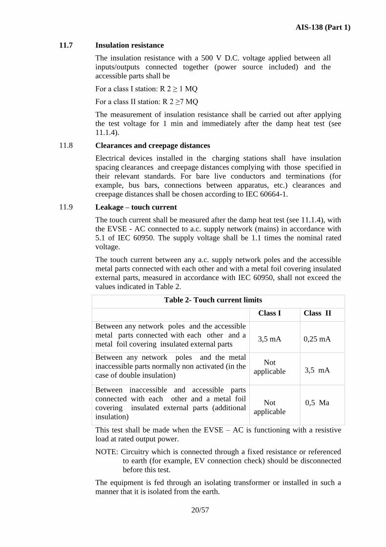
11.9 Leakage – touch current 20/57
11.10 Electrical safety 21/57
11.10.1 Protection against indirect contact 21/57
11.10.2 Earthing electrode and continuity 21/57
11.10.3 Detection of the electrical continuity of the protective
conductor
21/57
11.11 Environmental tests 21/57
AIS-138 (Part 1)
VI
11.11.1 Climatic environmental tests 21/57
11.11.2 Mechanical environmental tests 26/57
11.11.3 Electromagnetic environmental tests 28/57
11.12 Latching of the retaining device 32/57
11.13 Service 32/57
11.14 Marking and instructions 32/57
11.14.1 Connection instructions 33/57
11.14.2 Legibility 33/57
11.14.3 Marking of EVSE - AC 33/57
11.15 Telecommunication network 33/57
ANNEX A: Pilot function through a control pilot circuit using PWM
modulation and a control pilot wire
34/57
ANNEX B: Example of a circuit diagram for a basic vehicle coupler 41/57
ANNEX C: Connectors for AC Slow Charging and AC Fast Charging 45/57
ANNEX D: Cable Assembly for AC Slow Charging and AC Fast
Charging
47/57
ANNEX E: EVSE Categories Based On Load Capacity 51/57
ANNEX F: Power Converters (AC to DC) 52/57
ANNEX G: Periodic Compliance of EVSE 53/57
ANNEX H: Technical information to be submitted by component
manufacturer.
54/57
ANNEX I: Composition of AISC Panel 55/57
ANNEX J: Committee Composition 57/57
AIS-138 (Part 1)
1/57
Electric Vehicle Conductive AC Charging System
1.0 SCOPE
This standard applies to charging electric road vehicles at standard a.c.
supply voltages (as per IS 12360/IEC 60038) up to 1000 V and for
providing electrical power for any additional services on the vehicle if
required when connected to the supply network.
Electric road vehicles (EV) implies all road vehicles (2/3/4 Wheelers),
including plug in hybrid road vehicles (PHEV), that derive all or part of
their energy from on-board batteries.
The aspects covered include characteristics and operating conditions of the
supply device and the connection to the vehicle, operators and third party
electrical safety, and the characteristics to be complied with by the vehicle
with respect to the EVSE-AC, only when the EV is earthed.
Requirements for specific inlet, connector, plug and socket-outlets for EVs
are referred in AIS-038(Rev.1). This standard does not cover all safety
aspects related to maintenance.
This standard is not applicable to trolley buses, rail vehicles and off-road
industrial vehicles.
2.0 REFERENCES
The following referenced documents are indispensable for the application
of this document.
For dated references, only the edition cited applies. For undated references,
the latest edition of the referenced document (including any amendments)
applies.
IEC 61851 – 1 Electric vehicle conductive charging system Part 1:
General requirements.
IEC 61851 – 22 Electric vehicle conductive charging system Part
22: AC electric vehicle charging station.
IS 12360:1988/ IEC
60038:2009
Voltage bands for electrical installations including
preferred voltages and frequency.
IEC 60068-2-30:2005 Environmental testing – Part 2-30: Tests – Test Db:
Damp heat, cyclic (12 + 12 h cycle).
IS 9000(Part 7/Sec
7):2006/ IEC 60068-
2-75:1997
Basic environmental testing procedures for
electronic and electrical items: Part 7: Test Impact,
Sec 7 Test Eh: Hammer tests.
IS 9000 (Part 4):
2008/ IEC 60068-2-
78:2001
Basic environmental testing procedures for
electronic and electrical items: Part 4 DAMP
HEAT (STEADY STATE).
AIS-138 (Part 1)
2/57
IS/IEC 60309 (Part 1):
2002/ IEC 60309-
1:1999
Plugs, socket outlets and couplers for industrial
purpose Part 1 General requirements.
IS/IEC 60309-2:1999/
IEC 60309-2:1999
Plugs, socket-outlets and couplers for industrial
purposes – Part 2: Dimensional interchangeability
requirements for pin and contact-tube accessories.
SP 30: 2011 National Electrical Code (first revision)
IEC 60364-4-41:2005 Low-voltage electrical installations – Part 4-41:
Protection for safety – Protection against electric
shock.
IS/IEC 60529: 2001 Degrees of protection provided by enclosures (IP
Code).
IS 15382 (Part 1):
2014/ IEC 60664-
1:2007
Insulation coordination for equipment within low-
voltage systems – Part 1: Principles, requirements
and tests.
IEC/TR 60755:2008 General requirements for residual current
operated protective devices
IS 1293:2005/ IEC
60884-1:2002
Plugs and socket-outlets for household and
similar purposes – Part 1: General requirements.
IEC 60884-2-5:1995 Plugs and socket-outlets for household and
similar purposes – Part 2 particular requirements
for adaptors.
IEC 60947-3:2008 Low-voltage switchgear and control gear – Part 3:
Switches, disconnectors, switch-disconnectors
and fuse-combination units.
IS 13252 (Part 1):
2010/ IEC 60950-
1:2005
Information technology equipment — Safety —
Part 1: General requirements.
IS/IEC 60990: 1999 Methods of measurement of touch current and
protective conductor current.
IS 14700 (Part 6/Sec 1)/
IEC 61000-6-1:2005
Electromagnetic compatibility (EMC) – Part 6-1:
Generic standards – Immunity for residential,
commercial and light-industrial environments.
IS 14700 (Part 6/Sec 3)/
IEC 61000-6-3:2006
Electromagnetic compatibility (EMC) – Part 6-3:
Generic standards – Emission standard for
residential, commercial and light-industrial
environments.
IEC 61008-1:2010 Residual current operated circuit-breakers
without integral overcurrent protection for
household and similar uses (RCCBs) – General
rules.
IEC 61009-1:2010 Residual current operated circuit-breakers with
integral overcurrent protection for household and
similar uses (RCBOs) – General rules.
AIS-138 (Part 1)
3/57
IEC 61180-1:1992 High-voltage test techniques for low-voltage
equipment – Part 1: definitions, test and
procedure requirements.
IEC 62196-1:2003 Plugs, socket-outlets, vehicle couplers and
vehicle inlets – Conductive charging of electric
vehicles Part 1: Charging of electric vehicles up
to 250 A a.c. and 400 A d.c.
ISO 6469-2:2009 Electrically propelled road vehicles – Safety
specifications – Part 2: Vehicle operational safety
means and protection against failures.
ISO 6469-3:2001 Electric road vehicles – Safety specifications –
Part 3: Protection of persons against electric
hazards.
EN 50065-1:2001 Signalling on low-voltage electrical installations
in the frequency range 3 kHz to 148.5 kHz – Part
1: General requirements, frequency bands and
electromagnetic disturbances.
IS 9000 (Part 2): 1977 /
IEC 60068-2-1:1990
Environmental testing- Part 2: Tests - Tests A:
Cold.
IS 9000 (Part 3/ sec 1):
1977/ IEC 60068-2-
2:1974
Environmental testing- Part 2: Tests- Tests 8: Dry
heat.
IS 9000 (Part 4): 1979/
IEC 60068-2-3:1969
Environmental testing-Part 2: Tests- Test Ca:
Damp heat, steady state.
IS 9000 (Part 17): 1985
/ IEC 60068-2-5:1975
Environmental testing-Part 2: Tests- Test Sa:
Simulated solar radiation at ground level.
IS 9000 (Part 14/Sec 2):
1988 /IEC 60068-2-
14:1984
Environmental testing- Part 2: Tests- Test N:
Change of temperature.
IS 9000 (Part 5/Sec 1):
1981/ IEC 60068-2-
30:1980
Environmental testing - Part 2: Tests- Test Db
and guidance: Damp heat, cyclic (12 + 12-hour
cycle)
IEC 60068-2-52:1996 Environmental testing - Part 2: Tests - Test Kb:
Salt mist, cyclic (sodium chloride solution)
IS 9000(Part 7/Sec 7):
2006 / IEC 60068-2-
75:1997
Environmental testing- Part 2: Tests - Test Eh:
Hammer tests
IEC 61000-2-2:1990 Electromagnetic compatibility (EMC) -
Part 2: Environment - Compatibility levels for
low-frequency conducted disturbances and
signaling in public low-voltage power supply
systems
AIS-138 (Part 1)
4/57
IEC 61000-3-2:2000 Electromagnetic compatibility (EMC) - Part 3-
2: Limits - Limits for harmonic current emissions
(equipment input current: 516 A per phase)
IS 14700 (Part 4/Sec
1): 1999 / IEC 61000-
4-1:2000
Electromagnetic compatibility (EMC) - Part 4-1:
Testing and measurement techniques - Overview
of lEC 61000-4 series
IEC 61000-4-2:1995
Electromagnetic compatibility (EMC) - Part 4-2:
Testing and measurement techniques - Section 2:
Electrostatic discharge immunity test - Basic
EMC publication 2) with Amendment 1 (1998)
and Amendment 2 (2000)
IS 14700 (Part 4/Sec 3)
/ IEC 61000-4-3:1995
Electromagnetic compatibility (EMC) - Part 4:
Testing and measurement techniques - Section 3:
Radiated, radio-frequency, electromagnetic field
immunity test 3) with Amendment 1 (1998) and
Amendment 2 (2000)
IS 14700 (Part 4/Sec
4): 1999 / IEC 61000-
4-4:1995
Electromagnetic compatibility (EMC) - Part 4:
Testing and measurement techniques - Section 4:
Electrical fast transient/burst immunity test -
Basic EMC publication Amendment 1 (2000)
IS 14700 (Part 4/Sec 5)
/ IEC 61000-4-5:1995
Electromagnetic compatibility (EMC) - Part 4:
Testing and measurement techniques - Section 5:
Surge immunity test
IS 14700(Part 4: Sec
11):2008 / IEC 61000-
4-11:1994
Electromagnetic compatibility (EMC) - Part 4:
Testing and measurement techniques - Section
11: Voltage dips, short interruptions and voltage
variations immunity tests
IEC 61180-1:1992 High-voltage test techniques for low-voltage
equipment - Part 1: Definitions, test and
procedure requirements
CISPR 16 all parts) Specification for radio disturbance and immunity
measuring apparatus and methods
CISPR 22:1997 Information technology equipment- Radio
disturbance characteristics- Limits and methods
of measurement
3.0
TERMS AND DEFINITIONS
For the purposes of this standard, the following terms and definitions apply.
3.1 “Basic insulation” Insulation of hazardous-live-parts which provides basic
protection.
3.2 “Cable assembly” Piece of equipment used to establish the connection
between the EV and socket-outlet or to the fixed charger.
NOTE 1: It must be included in the EVSE or detachable (supplied with the
vehicle).
AIS-138 (Part 1)
5/57
NOTE 2: It includes the flexible cable and the connector and/or plug that
are required for proper connection.
NOTE 3: A detachable cable assembly is not considered as a part of the
fixed installation.
3.3 “Charger” Power converter that performs the necessary functions for
charging a battery.
3.3.1 “Class I charger” Charger with basic insulation as provision for basic
protection and protective bonding as provision for fault protection.
NOTE: Protective bonding consists of connection of all exposed conductive
parts to the charger earth terminal.
3.3.2 “Class II charger” Charger with:
– Basic insulation as provision for basic protection, and
– Supplementary insulation as provision for fault protection, or in which
– Basic and fault protection are provided by reinforced insulation.
3.3.3 “Off-board charger” Charger connected to the premises wiring of the a.c.
supply network (mains) and designed to operate entirely off the vehicle. In
this case, direct current electrical power is delivered to the vehicle.
3.3.3.1 “Dedicated off-board charger” Off-board charger designed to be used
only by a specific type of EV, which may have control charging functions
and/or communication.
3.3.4 “On-board charger” Charger mounted on the vehicle and designed to
operate only on the vehicle.
3.4 “Charging” All functions necessary to condition standard voltage and
frequency AC supply current to a regulated voltage/current level to assure
proper charging of the EV traction battery and/or supply of energy to the
EV traction battery bus, for operating on-board electrical equipment in a
controlled manner to assure proper energy transfer.
3.4.1 “AC Slow Charging” Charging with 1 Phase, 15 A Outlet with connector
IEC 60309 and related safety interlocks. For details refer 6.2.1.
3.4.2 “AC Fast Charging” Charging with 3 Phase, 63 A Outlet with connector
IEC 62196 and related safety interlocks. For details refer 6.2.2.
3.5 “Connection” Single conductive path.
3.6 “Control pilot” Control pilot is the control conductor in the cable
assembly connecting the in-cable control box or the fixed part of the EVSE,
and the EV earth through the control circuitry on the vehicle. It may be
used to perform several functions.
3.7 “Protective Earth (PE) terminal” Accessible connection point for all
exposed conductive parts electrically bound together.
3.8 “Electric vehicle/ EV/ Electric road vehicle (ISO)” Any vehicle
propelled by an electric motor drawing current from a rechargeable storage
battery or from other portable energy storage devices (rechargeable, using
energy from a source off the vehicle such as a residential or public electric
service), which is manufactured primarily for use on public streets, roads or
highways.
AIS-138 (Part 1)
6/57
3.8.1 “Class I EV” An EV with basic insulation as provision for basic protection
and protective bonding as provision for fault protection.
NOTE: This consists of connection of all exposed conductive parts to the
EV earth terminal.
3.8.2 “Class II EV” An EV in which protection against electric shock does not
rely on basic insulation only, but in which additional safety precautions,
such as double insulation or reinforced insulation, are provided, there being
no provision for protective earthing or reliance upon installation conditions.
3.9 “EV supply equipment / EVSE” Conductors, including the phase, neutral
and protective earth conductors, the EV couplers, attachment plugs, and all
other accessories, devices, power outlets or apparatuses installed
specifically for the purpose of delivering energy from the premises wiring
to the EV and allowing communication between them if required.
3.9.1 “EVSE AC” All equipment for delivering a.c. current to EVs, installed in
an enclosure(s) and with dedicated functions.
3.9.1.1 “EVSE AC Slow” EVSE that supports AC Slow type of charging as
defined in 3.4.1.
3.9.1.2 “EVSE AC Fast” EVSE that supports AC Fast type of charging as defined
in 3.4.2.
3.9.2 “Exposed conductive part” Conductive part of equipment, which can be
touched and which is not normally live, but which can become live when
basic insulation fails.
3.9.3 “Direct contact” Contact of persons with live parts.
3.9.4 “Indirect contact” Contact of persons with exposed conductive parts made
live by an insulation failure.
3.10 “Live part” Any conductor or conductive part intended to be electrically
energized in normal use.
3.10.1 “Hazardous live part” Live part, which under certain conditions, can
result in an electric shock.
3.12 “Plug and socket-outlet” Means of enabling the manual connection of a
flexible cable to fixed wiring.
NOTE: It consists of two parts: a socket-outlet and a plug.
3.12.1 “Plug” Part of a plug and socket-outlet integral with or intended to be
attached to the flexible cable connected to the socket-outlet.
3.12.2 “Socket-outlet” Part of a plug and socket-outlet intended to be installed
with the fixed wiring.
3.13 “Power indicator” Resistor value identifying supply rating recognition by
the vehicle.
3.14 “Retaining device” Mechanical arrangement which holds a plug or
connector in position when it is in proper engagement, and prevents
unintentional withdrawal of the plug or connector.
3.15 “Vehicle coupler” Means of enabling the manual connection of a flexible
cable to an EV for the purpose of charging the traction batteries.
NOTE: It consists of two parts: a vehicle connector and a vehicle inlet.
AIS-138 (Part 1)
7/57
3.15.1 “Vehicle connector” Part of a vehicle coupler intended to be attached to
the flexible cable connected to the a.c. supply network (mains).
3.15.2 “Vehicle inlet” Part of a vehicle coupler incorporated in, or fixed to, the
EV or intended to be fixed to it.
3.16 “Function” Any means, electronic or mechanical, that insure that the
conditions related to the safety or the transmission of data required for the
mode of operation are respected.
3.17 “Pilot function” Any means, electronic or mechanical, that insures the
conditions related to the safety or the transmission of data required for the
mode of operation.
3.18 “Proximity function” A means, electrical or mechanical, in a coupler to
indicate the presence of the vehicle connector to the vehicle.
3.19 “Standardized socket-outlet for EVSE AC Slow”
IEC 60309 Industrial connector (Refer Annex C for connector details)
3.20 “Standardized socket-outlet for EVSE AC Fast”
IEC 62196 Type 2 Connector (Refer Annex C for connector details)
3.21 “Residual Current Device (RCD)” Mechanical switching device designed
to make, carry and break currents under normal service conditions and to
cause the opening of the contacts when the residual current attains a given
value under specified conditions.
NOTE 1: A residual current device can be a combination of various
separate elements designed to detect and evaluate the residual current and
to make and break current (IEC 60050-44:1998, 442-05-02).
3.22 “Plug in Hybrid Electric road vehicle PHEV” Any electrical vehicle that
can charge the rechargeable electrical energy storage device from an
external electric source and also derives part of its energy from another
source.
3.23 “Cord extension set” Assembly consisting of a flexible cable or cord fitted
with both a plug and a connector.
NOTE: Detachable cable assembly supplied with the vehicle is not
considered as a cord extension set.
3.24 “Adaptor” A portable accessory constructed as an integral unit
incorporating both a plug portion and one or more socket-outlets.
3.25 “Indoor use” Equipment designed to be exclusively used in weather
protected locations.
3.26 “Outdoor use” Equipment designed to be allowed to be used in non-
weather protected locations.
3.27 “Mandatory Safety functions” Mandatory Safety functions to be included
in the EVSE. For details, refer 6.4.1.
3.28 “Optional Safety functions” Optional functions are functions that may
enhance the performance or improve safety of the EVSE. For details, refer
6.4.2.
AIS-138 (Part 1)
8/57
3.29 “Extra Low Voltage” Extra-low Voltage (ELV) voltage range should be
considered as:
Voltage ≤ 30 Vrms, 42.4 Vpk and 60 VDC; no risk of shock.
3.30 “Hazardous Live Voltage” Hazardous LIVE Voltage range should be
considered as:
Voltage > 30 Vrms, 42.4 Vpk and 60 VDC; risk of shock, burn, or fire.
3.31 “Power Converter (AC to DC)” A power Converter is an AC-DC
Converter device connected in-line with charging connector Cable A to
fulfil DC power requirements for charging of Electric Vehicles with
maximum power rating of 1.1kW.
4.0 GENERAL REQUIREMENTS
The EV shall be connected to the EVSE so that in normal conditions of use,
the conductive energy transfer function operates safely.
In general, this principle is achieved by fulfilling the relevant requirements
specified in this standard, and compliance is checked by carrying out all
relevant tests.
**Periodic compliance of EVSE is to be ensured by authorised agencies.
5.0 RATING OF THE SUPPLY A.C. VOLTAGE
The rated value of the a.c. supplied voltage for the charging equipment is
up to 1000 V. The equipment shall operate correctly within ±10 % of the
standard nominal voltage. The rated value of the frequency is 50 Hz ± 3%.
NOTE: Nominal voltage values can be found in IS 12360.
6.0 GENERAL SYSTEM REQUIREMENT AND INTERFACE
6.1 General description
One method for EV charging is to connect the a.c. supply network (mains)
to an on-board charger. An alternative method for charging an EV is to use
an off-board charger for delivering direct current. For charging in a short
period of time, special charging facilities operating at high power levels
could be utilized.
AIS-138 (Part 1)
9/57
6.2 EV charging modes
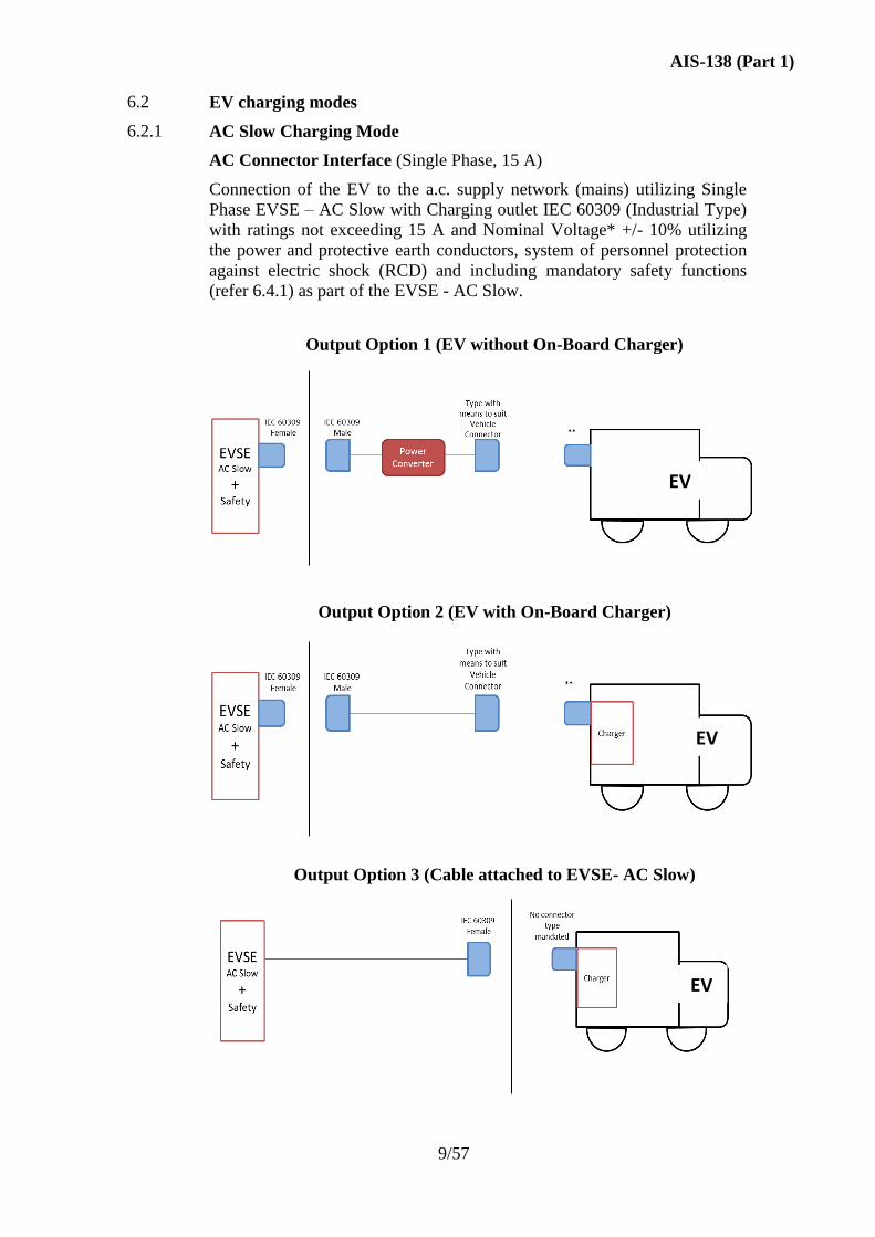
6.2.1 AC Slow Charging Mode
AC Connector Interface (Single Phase, 15 A)
Connection of the EV to the a.c. supply network (mains) utilizing Single
Phase EVSE – AC Slow with Charging outlet IEC 60309 (Industrial Type)
with ratings not exceeding 15 A and Nominal Voltage* +/- 10% utilizing
the power and protective earth conductors, system of personnel protection
against electric shock (RCD) and including mandatory safety functions
(refer 6.4.1) as part of the EVSE - AC Slow.
Output Option 1 (EV without On-Board Charger)
Output Option 2 (EV with On-Board Charger)
Output Option 3 (Cable attached to EVSE- AC Slow)
EV
EV
EV
AIS-138 (Part 1)
10/57
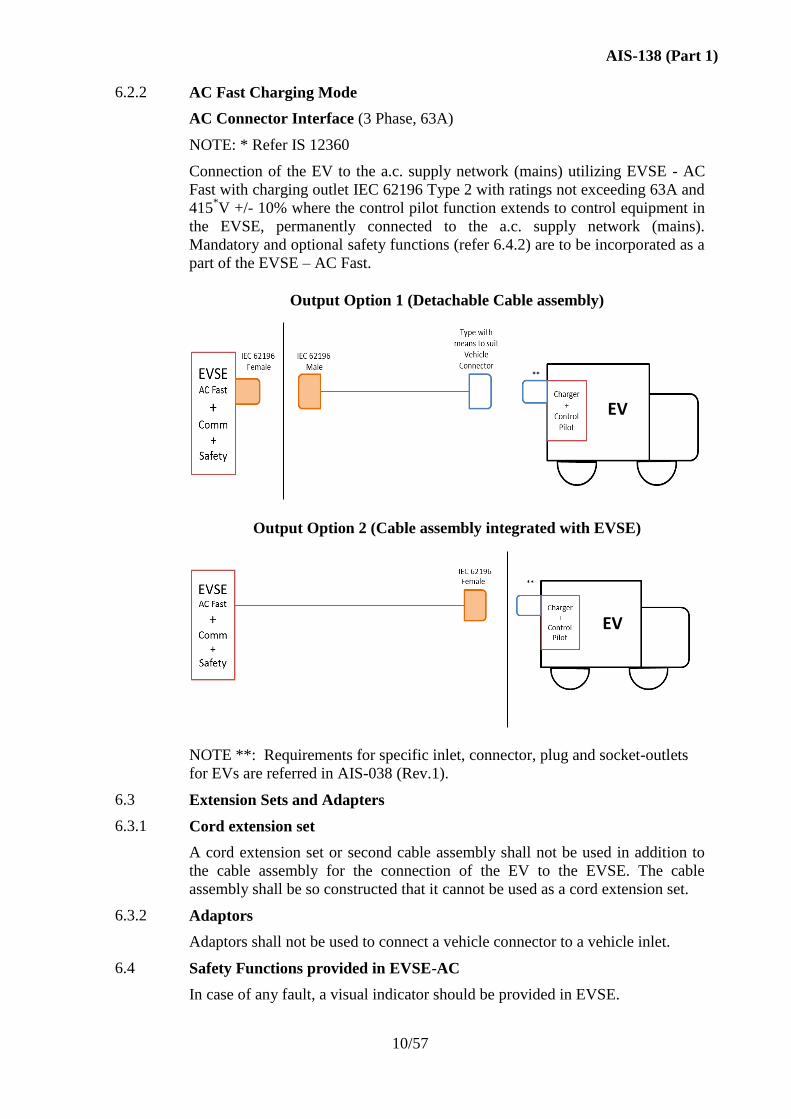
6.2.2 AC Fast Charging Mode
AC Connector Interface (3 Phase, 63A)
NOTE: * Refer IS 12360
Connection of the EV to the a.c. supply network (mains) utilizing EVSE - AC
Fast with charging outlet IEC 62196 Type 2 with ratings not exceeding 63A and
415*V +/- 10% where the control pilot function extends to control equipment in
the EVSE, permanently connected to the a.c. supply network (mains).
Mandatory and optional safety functions (refer 6.4.2) are to be incorporated as a
part of the EVSE – AC Fast.
Output Option 1 (Detachable Cable assembly)
Output Option 2 (Cable assembly integrated with EVSE)
NOTE **: Requirements for specific inlet, connector, plug and socket-outlets
for EVs are referred in AIS-038 (Rev.1).
6.3 Extension Sets and Adapters
6.3.1 Cord extension set
A cord extension set or second cable assembly shall not be used in addition to
the cable assembly for the connection of the EV to the EVSE. The cable
assembly shall be so constructed that it cannot be used as a cord extension set.
6.3.2 Adaptors
Adaptors shall not be used to connect a vehicle connector to a vehicle inlet.
6.4 Safety Functions provided in EVSE-AC
In case of any fault, a visual indicator should be provided in EVSE.
EV
EV
AIS-138 (Part 1)
11/57
6.4.1 Details of Mandatory Safety Functions
6.4.1.1 Earth Presence Detection (Socket - EVSE)
Validate the presence of earth at the AC socket outlet during start of charging
session and continuous/periodic monitoring during the charging session.
6.4.1.2 Earth Continuity Check (EVSE-EV)
Presence of earth between EV and EVSE during charging session is to be
monitored. In AC Slow Charging, this is to be ensured at the vehicle side.
6.4.1.3 Over-voltage Protection
The EVSE should have protection against Over-Voltage.
6.4.1.4 Under-Voltage Protection
The EVSE should have protection against Under-Voltage.
6.4.1.5 Over Current and Short-Circuit Protection
The EVSE should have protection against Over-Current and Short-Circuit.
6.4.1.6 Leakage Current
Fault or leakage current inside the EVSE is to be detected and protection is to
be provided in case of detection. Type of RCD (Type A minimum) and Fault
Current Limit 30 mA.
6.4.1.7 Connector Presence & Locking
It should be verified that the connector is properly connected and Connector is
locked during charging period of the charge session to avoid accidental/
unintentional disconnection. For AC Slow charging connector, this is to be
ensured by physical attributes.
6.4.1.8 Environmental Protection
The EVSE should have protection against environmental conditions like Solar
Radiation, Temperature, and Water.
Note: The protection against Environmental conditions will be checked under
11.4 and 11.11.
6.4.1.9 Protection when Phase -Neutral Interchange occurs
Charging function for vehicle may not be inhibited provided mandatory safety
is fully functional even in case of Phase-Neutral interchange condition.
6.4.2 Details of Optional Safety functions
6.4.2.1 Verification that the vehicle is properly connected
The EVSE-AC Fast shall be able to determine that the connector is properly
inserted in the vehicle inlet and properly connected to the EVSE. Vehicle
movement by its own propulsion system shall be impossible as long as the
vehicle is physically connected to the EVSE as required in ISO 6469-2.
6.4.2.2 Energization of the system
Energization of the system shall not be performed until the pilot function
between EVSE and EV has been established correctly. Energization may also
be subject to other safety conditions being fulfilled.
AIS-138 (Part 1)
12/57
6.4.2.3 De-energization of the system
If the pilot function is interrupted, the power supply to the cable assembly
shall be interrupted but the control circuit may remain energized.
6.4.2.4 Input Power Quality
Monitor the AC supply (Rated Power, Voltage and Frequency Tolerance) for
possible faults and include necessary corrective measures.
6.4.2.5 Fail Safe Handling
Fail-safe operations should function when certain faults occur.
6.4.2.6 Determination of ventilation requirements during charging
If additional ventilation is required during charging, charging shall only be
allowed if such ventilation is provided.
6.4.2.7 Detection/adjustment of the real time available load current of EVSE
Means shall be provided to ensure that the charging rate shall not exceed the
real time available load current of the EVSE and its power supply.
6.4.2.8 Retaining/releasing of the coupler
A mechanical means shall be provided to retain/release the coupler.
6.4.2.9 Selection of charging rate
A manual or automatic means shall be provided to ensure that the charging
rate does not exceed the rated capacity of the a.c. supply network (mains),
vehicle or battery capabilities.
6.4.3 Details of pilot function
For AC Fast Charging mode, a pilot function is mandatory. The pilot function
shall be capable of performing at least the mandatory safety functions
described above and may be capable of performing/contributing in optional
functions.
NOTE: For details of Pilot Function and relevant examples refer Annex A.
6.4.4 Details of Proximity function
For AC Fast Charging mode, Proximity function is mandatory.
NOTE: For implementation details Annex B can be referred.
6.5 Vehicle Identification Functions provided in EVSE-AC
Reserved
6.6 Energy Metering Functions provided in EVSE-AC
Reserved
6.7 Functions related to Communication to Grid
Reserved
AIS-138 (Part 1)
13/57
7.0 PROTECTION AGAINST ELECTRIC SHOCK
7.1 General requirements
Hazardous live parts shall not be accessible. Exposed conductive parts shall
not become a hazardous live part under normal conditions (operation as
intended use and in the absence of a fault), and under single-fault conditions.
Protection against electric shock is provided by the application of appropriate
measures for protection both in normal service and in case of a fault. For
systems or equipment on board the vehicle, the requirements are defined in
AIS-038 (Rev.1) – For systems or equipment external to the vehicle, the
requirements are defined in SP 30: 2011 /IEC 60364-4-41.
7.2 Protection against direct contact
7.2.1 General
Protection against direct contact shall consist of one or more provisions that
under normal conditions prevent contact with hazardous-live parts. For
systems or equipment on board the vehicle, the requirements are defined in
AIS-038 (Rev.1).
Protective bonding shall consist of connection of all exposed conductive parts
to the EV earth terminal.
7.2.2 Accessibility of live parts
When connected to the supply network, the EVSE shall not have any
accessible hazardous live part, even after removal of parts that can be removed
without a tool.
All accessible parts (eg. metal enclosures) must be prevented from becoming
hazardous live. For details of Hazardous live Voltage refer Section 3.
Compliance is checked by inspection and according to the requirements of
IS/IEC 60529 (IPXXB).
NOTE: Extra Low Voltage (ELV) auxiliary circuits which are galvanically
connected to the vehicle body are accessible. Particular attention is drawn to
the requirements for ELV circuit isolation when the traction battery is being
charged using a non-isolated charger.
7.2.3 Stored energy – discharge of capacitors
7.2.3.1 Disconnection of EV
One second after having disconnected the EV from the supply (mains), the
voltage between accessible conductive parts or any accessible conductive part
and earth shall be less than or equal to 42,4 V peak, or 60 V D.C., and the
stored energy available shall be less than 20 J (see IS 13252/IEC 60950). If
the voltage is greater than 42,4 V peak (30 V rms) or 60 V D.C., or the energy
is 20 J or more, a warning label shall be attached in an appropriate position.
Compliance is checked by inspection and by test.
7.2.3.2 Disconnection of EVSE
Conditions for the disconnections of the EVSE from the supply mains are
identical to those required for the disconnection of the EV as indicated in
7.2.3.1.
AIS-138 (Part 1)
14/57
7.3 Fault protection
Protection against indirect contact shall consist of one or more recognized
provision(s).
According to SP 30: 2011 /IEC 60364-4-41, recognized individual provisions
for fault protection are:
– Supplementary or reinforced insulation;
– Protective equipotential bonding;
– Protective screening;
– Automatic disconnection of supply;
– Simple separation.
7.4 Supplementary measures
To avoid indirect contact in case of failure of the basic and/or fault protection
or carelessness by users, additional protection against electric shock shall be
required.
An RCD (I∆N < 30 mA) shall be provided as a part of the EV conductive
supply equipment for earthed systems. The RCD shall have a performance at
least equal to Type A and be in conformity with standard SP 30: 2011 /IEC
60364-4-41.
Where power supply circuits that are galvanically separated from mains and
are galvanically isolated from earth, electrical isolation between the isolated
circuits and earth, and between the isolated circuits and exposed conductive
parts of vehicle and EVSE shall be monitored.
When a fault condition related to the electrical isolation is detected, the power
supply circuits shall be automatically de-energized or disconnected by the
EVSE.
7.5 Additional requirements
Under normal conditions, malfunction and single-fault conditions, the
charging system shall be designed to limit the introduction of harmonic, D.C.
and non-sinusoidal currents that could affect the proper functioning of residual
current devices or other equipment.
Class II chargers may have a lead - through protective conductor for earthing
the EV chassis.
8.0 CONNECTION BETWEEN THE EVSE AND THE EV
8.1 General
This clause provides a description of the physical conductive electrical
interface requirements between the vehicle and the EVSE.
Contact Number IEC 60309 IEC 62196 Function
1 Single Phase, 15 A Three Phase, 63 A L1
2 Three Phase, 63 A L2
3 Three Phase, 63 A L3
AIS-138 (Part 1)
15/57
4 Single Phase, 15 A Three Phase, 63 A Neutral
5 Rated for fault Rated for Fault PE
6 Control Pilot
7 Proximity
For details, refer Annex C and Annex D.
8.2 Contact sequencing for AC Fast Charging
For safety reasons, the contact sequence during the connection process shall
be such that the earth connection is made first and the pilot connection is made
last. The order of connection of the other contacts is not specified. During
disconnection, the pilot connection shall be broken first and the earth
connection shall be broken last.
9.0 SPECIFIC REQUIREMENTS FOR VEHICLE INLET, CONNECTOR,
PLUG AND SOCKET-OUTLET
9.1 General requirements
The requirements for accessories for AC Slow charging are specified in
IS/IEC 60309-1, IS/IEC 60309-2 (industrial type).
The requirements of EVSE systems for AC Fast Charging are specified in IEC
62196-1.
9.2 Operating temperature
The EVSE-AC should be fully functional with all safety features in the
temperature range of 0 to 55oC.
9.3 Service life of inlet/connector and plug/socket-outlet
The requirements for accessories of the standard interface are specified in
IS/IEC 60309-1, IS/IEC 60309-2 (industrial type).
The requirements for accessories of the interface are specified in IEC 62196-1.
9.4 Breaking capacity
The requirement for AC Slow Charging shall be in accordance with IEC
60309.
The requirement for AC Fast Charging shall be in accordance with IEC
62196-1.
For personal safety and to avoid damage due to disconnection under nominal
current, the plug, the inlet, the connector or the socket-outlet shall have
sufficient breaking capacity unless there is a switch with sufficient breaking
capacity. Acceptable breaking capacity is reached by breaker level for a.c.
application AC22A as defined in IS/IEC 60947-3, or breaker level for a.c.
application AC2 as defined in IS/ IEC 60947-6.
Avoidance of breaking under load can be achieved by a specific means on the
connector or a system with interlock.
AIS-138 (Part 1)
16/57
9.5 IP degrees
IP degrees for accessories are treated in 11.3.
9.6 Insertion and extraction force
The force required for connecting and disconnecting operations for the
connector and inlet is in accordance with IEC 60309 for AC Slow Charging
and IEC 62196-1 for AC Fast Charging.
9.7 Latching of the retaining device
Latching or retaining if required may be a function of the complete system or
the connector.
10.0 CHARGING CABLE ASSEMBLY REQUIREMENTS
10.1 Electrical rating
The rated voltage of each conductor shall correspond to the rated voltage of
the connecting means. The rated current shall correspond to the rating of the
line circuit breaker.
10.2 Electrical characteristics
The voltage and current ratings of the cable shall be compatible with those of
the charger.
The cable may be fitted with an earth-connected metal shielding. The cable
insulation shall be wear resistant and maintain flexibility over the full
temperature range.
For details, refer Annex D.
10.3 Dielectric withstand characteristics
Dielectric withstand characteristics shall be as indicated for the EVSE in 11.4.
10.4 Mechanical characteristics
The mechanical characteristics of the cable should be equivalent or superior to
those of IS 9857 / IEC 60245-6 (Welding cable) as well as for fire resistance,
chemical withstand, UV resistance.
The anchorage force of the cable in the connector or plug shall be greater than
the retaining device force, if used.
For details, refer Annex D
11.0 EVSE REQUIREMENTS 11.1 General test requirements
– All tests in this standard are type tests.
– Unless otherwise specified, type tests shall be carried out on a single
specimen as delivered and configured in accordance with the
manufacturer's instructions.
– The tests in 11.12 may be conducted on separate samples at the discretion
of the manufacturer. Unless otherwise specified, all other tests shall be
carried out in the order of the clauses and sub clauses in this part.
– The tests shall be carried out with the specimen, or any movable part of it,
placed in the most unfavourable position which may occur in normal use.
– Unless otherwise specified, the tests shall be carried out in a draught-free
AIS-138 (Part 1)
17/57
location and at an ambient temperature of 20 to 30 °C.
NOTE: For details, refer IEC 61851 – 22.
11.2 Standard conditions for operation in service and for installation
The rated value of the a.c. supply voltage is up to 1000 V. The equipment
shall operate correctly within ±10% of the standard nominal voltage (see IS
12360). The rated value of the frequency is 50 Hz ± 3%.
The operating temperature range during charging may be between 0 to 55 oC
and at a relative humidity of between 5 % and 95 %.
11.3 Classification
EVSE - AC shall be classified according to exposure to environmental
conditions:
– Outdoor use;
– Indoor use.
NOTE: EVSEs classified for outdoor use can be used for indoor use, provided
ventilation requirements are satisfied.
11.4 IP degrees for EVSE
11.4.1 IP degrees for ingress of objects
Compliance is checked by test in accordance with IS/IEC 60529.
The minimum IP degrees for ingress of object and liquids shall be:
Indoor use:
– Vehicle inlet mated with connector: IP21,
– Plug mated with socket outlet: IP21,
– Connector for Cable assembly integrated with EVSE, when not mated,
indoor: IP21.
Outdoor use:
– Vehicle inlet mated with connector: IP44,
– Plug mated with socket outlet: IP44.
All cable assemblies shall meet outdoor requirements.
– EV inlet in "road" position: IP55.
– Connector when not mated: IP24,
– Socket-outlet when not mated: IP24.
NOTE 1: IPX4 may be obtained by the combination of the socket-outlet or
connector and the lid or cap, EVSE - AC enclosure, or EV enclosure.
NOTE 2: EV inlet protection may be obtained by the combination of the inlet
and vehicle design.
11.4.2 Protection against electric shock
– Vehicle inlet mated with connector: IPXXD;
– Plug mated with socket outlet: IPXXD;
AIS-138 (Part 1)
18/57
– Connector intended for AC Slow Charging : IPXXD ;
– Connector intended for AC Fast Charging: IPXXB;
– Socket-outlet not mated: IPXXD (1).
– Energy transfer from vehicle to grid:
– Vehicle inlet not mated: IPXXD (2);
– Plug not mated: IPXXD (2).
Compliance is checked with the accessory in the installed position.
(1) Equivalent protection to IPXXD may also be obtained with IPXXB
accessories if an isolating function is used according SP 30: 2011 /IEC
60364-4-41.
(2) Equivalent protection to IPXXD may also be obtained with IPXXB
accessories if an isolating function is used on the vehicle according to
requirements described in AIS-038 (Rev.1).
11.5 Functional and constructional requirements
11.5.1 Control functions
For AC Fast charging, the EVSE Fast charger provides part of the control
functions listed in 6.4.
11.5.2 Emergency service
An emergency disconnection device shall be installed to isolate the a.c.
supply network (mains) from the EVSE - AC in case of risk of electric shock,
fire or explosion. The disconnection device shall be provided with a means to
prevent accidental operation.
11.5.3 Permissible surface temperature
The maximum permissible surface temperature of parts of the EVSE – AC
which are hand grasped, at the maximum rated current and at an ambient
temperature of 40 °C, shall be
50 °C for metal parts;
60 °C for non-metallic parts.
For parts which may be touched but not grasped, maximum permissible
surface temperature under the same conditions shall be
60 °C for metal parts;
85 °C for non-metallic parts.
11.5.4 Storage means for the cable assembly
For AC Fast charging output option-2 (refer 6.2.2) connections, a storage
means shall be provided for the cable assembly and vehicle connector when
not in use. The EVSE – AC Fast should be provided with a means to indicate
whether or not the cable assembly/vehicle connector has been stored as
intended after disconnection from the vehicle.
AIS-138 (Part 1)
19/57
11.5.5 Location of the socket-outlet and storage means for the connector
The lowest part of the socket-outlet (in output option 1 connections), or
the storage means provided for the vehicle connector (in output option 2
connection), shall be located at a height between 0.4 m and 1.5 m above
ground level in EVSE - AC Fast.
11.6 Dielectric withstand characteristics
11.6.1 Dielectric withstand voltage
The dielectric- withstand voltage at power frequency (50 Hz) shall be
applied for 1 min as follows:
a) For a class I a.c supply equipment
- 2000 V r.m.s. in common and differential mode*
b) For a class II a.c supply equipment
- 4000 V r.m.s. in common mode (all circuits in relation to the
exposed conductive part)
- 2000 V r.m.s. in differential mode* (between each electrically
independent circuit and all other exposed conductive part-oriented
circuits)
c) For both class I and class II a.c supply equipment
- 4000 V r.m.s. between power circuits and extra low voltage circuits
The tests shall be carried out in accordance with the requirements of IEC
61180-1.
NOTE: *Differential testing is applicable for EVSE- AC fast only.
Compliance/ Acceptance Criteria
Output voltage stability to be ensured after the test.
Insulation resistance to be verified.
Protection against output short circuit to be verified.
11.6.2 Impulse dielectric withstand (1,2/50 IJS)
The dielectric withstand of the power circuits at impulse shall be checked as
follows:
6000 V: in common mode (according to IEC 60664-1 installation category);
4000 V: in differential mode* (according to IEC 60664-1 installation
category).
The test shall be carried out in accordance with the requirements of
IEC 61180-1.
NOTE: *Differential testing is applicable for EVSE- AC fast only.
Compliance/ Acceptance Criteria
Output voltage stability to be ensured after the test.
Insulation resistance to be verified.
Protection against output short circuit to be verified.
AIS-138 (Part 1)
20/57
11.7 Insulation resistance
The insulation resistance with a 500 V D.C. voltage applied between all
inputs/outputs connected together (power source included) and the
accessible parts shall be
For a class I station: R 2 ≥ 1 MQ
For a class II station: R 2 ≥7 MQ
The measurement of insulation resistance shall be carried out after applying
the test voltage for 1 min and immediately after the damp heat test (see
11.1.4).
11.8 Clearances and creepage distances
Electrical devices installed in the charging stations shall have insulation
spacing clearances and creepage distances complying with those specified in
their relevant standards. For bare live conductors and terminations (for
example, bus bars, connections between apparatus, etc.) clearances and
creepage distances shall be chosen according to IEC 60664-1.
11.9 Leakage – touch current
The touch current shall be measured after the damp heat test (see 11.1.4), with
the EVSE - AC connected to a.c. supply network (mains) in accordance with
5.1 of IEC 60950. The supply voltage shall be 1.1 times the nominal rated
voltage.
The touch current between any a.c. supply network poles and the accessible
metal parts connected with each other and with a metal foil covering insulated
external parts, measured in accordance with IEC 60950, shall not exceed the
values indicated in Table 2.
Table 2- Touch current limits
Class I Class II
Between any network poles and the accessible
metal parts connected with each other and a
metal foil covering insulated external parts
3,5 mA
0,25 mA
Between any network poles and the metal
inaccessible parts normally non activated (in the
case of double insulation)
Not
applicable
3,5 mA
Between inaccessible and accessible parts
connected with each other and a metal foil
covering insulated external parts (additional
insulation)
Not
applicable
0,5 Ma
This test shall be made when the EVSE – AC is functioning with a resistive
load at rated output power.
NOTE: Circuitry which is connected through a fixed resistance or referenced
to earth (for example, EV connection check) should be disconnected
before this test.
The equipment is fed through an isolating transformer or installed in such a
manner that it is isolated from the earth.
AIS-138 (Part 1)
21/57
11.10 Electrical safety
The general requirements for electrical safety are specified in 7. In addition,
the following requirements apply.
11.10.1 Protection against indirect contact
The protection against electric shock shall not be automatically reset. Manual
reset shall be easily accessible to the user. Automatic reset of optional
additional protection devices, as specified in 7, shall comply with national
regulations.
11.10.2 Earthing electrode and continuity
The tests for a class I charging station earth electrode, where applicable, and
earthing of the EVSE- AC shall be carried out in accordance with the national
rules and safety requirements for earthing.
All exposed conductive parts of the EVSE - AC which could be connected to
the supply voltage source, under fault conditions, shall be connected together
in such a manner that they conduct electricity properly, so as to conduct
potential fault currents to the earthed point of the a.c. supply network (mains).
Compliance is checked by testing the electrical continuity between exposed
conductive parts and the earth circuit.
A current of 15 A, derived from a D.C. source having a no-load voltage not
exceeding 12 V, is passed between any exposed conductive part and the
earthing terminal of the charging station. For each exposed conductive part,
the voltage drop is measured between these two points.
The resistance calculated from the current and measured voltage drop,
between any exposed conductive part and the earth-circuit connection, shall
not exceed 0.1 ohm.
For a class II charging station, there shall be a lead-through protective
conductor.
11.10.3 Detection of the electrical continuity of the protective conductor
For AC Fast charging, the EVSE - AC Fast shall monitor the electrical
continuity of the protective conductor to the electric vehicle. If the EVSE
detects a loss of electrical continuity of the protective conductor, the
electrical supply circuit to the vehicle shall be opened.
11.11 Environmental tests
11.11.1 Climatic environmental tests
11.11.1.1 General
During the following tests, the EVSE - AC shall function at its nominal
voltage with maximum output power and current. After each test, the
original requirements shall still be met.
11.11.1.2 Ambient air temperature
The EVSE - AC shall be designed to operate within the temperature range
0 °C to +55 °C.
AIS-138 (Part 1)
22/57
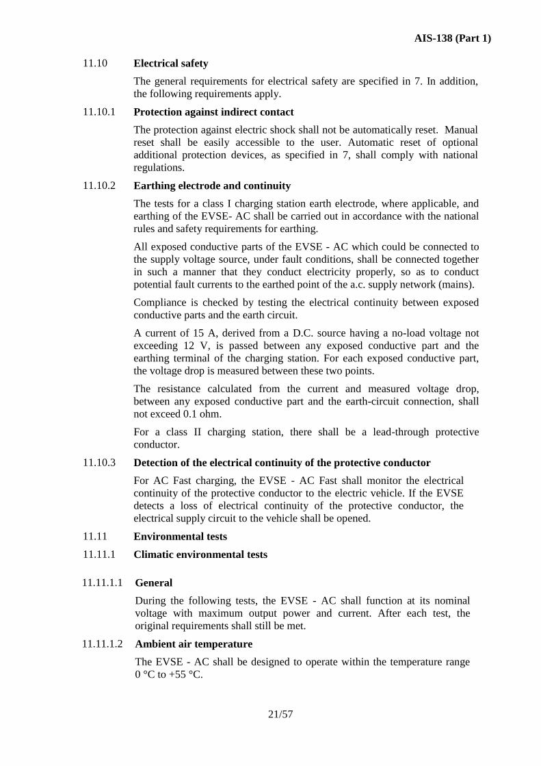
These tests shall be carried out in accordance with the Nb test (change of
temperature with specified rate of change) of IEC 60068-2-14/ IS 9000
(Part 14) - sec 2.
Test Cycle
Test Parameters
Parameter Value Unit
Low temp TA 0 °C
High temp TB +55 °C
Rate of Temp (Max) 1 °C/min
Time t1 1 h
No of cycles 2 --
EVSE Condition
Power ON with output loading for maximum power and current.
EVSE Monitoring
Periodic measurements of output power and current during the test.
Compliance/ Acceptance Criteria
Output power and current values to be within specified band
Safety checks
- To ensure protection against short circuit
- To check the insulation resistance
11.11.1.3 Dry heat
The test shall be in accordance with IEC 60068-2-2 Bc or Bd test (dry heat)/
IS 9000 (Part 3) - sec 5.
Test Parameters
Parameter Value Unit
Temperature 55 °C
Relative humidity <50 %
AIS-138 (Part 1)
23/57
Rate of Temp (Max) 1 °C/min
Duration 16 h
EVSE Condition
Power ON with output loading for maximum power and current.
EVSE Monitoring
Periodic measurements of output power and current during the test.
Compliance/ Acceptance Criteria
Output power and current values to be within specified band
Safety checks
- To ensure protection against short circuit
- To check the insulation resistance
11.11.1.4 Ambient humidity
The EVSE -AC shall be designed to operate with a relative humidity rate
between 5 % and 95 %.
Damp heat cycle test
The test shall be carried out in accordance with IEC 60068-2-30/ IS
9000(Part 5 /Sec 2), test Db, at 55°C for six cycles.
Test Parameters
Parameter Value Unit
Temperature 55 °C
Relative humidity 95 %
Rate of Temp (Max) 1 °C/min
Duration 12 + 12 hours
No of cycles 6
EVSE Condition
Power ON with output loading for maximum power and current.
EVSE Monitoring
Periodic measurements of output power and current during the test.
Compliance/ Acceptance Criteria
Immediately after damp heat within 1 min, Insulation Resistance test to be
performed.
Output power and current values to be within specified band.
Safety checks to ensure protection against short circuit.
11.11.1.5 Cold test
The test shall be carried out in accordance with IEC 60068-2-1 test Ab/ IS
9000 (Part 2) - sec 3.
AIS-138 (Part 1)
24/57
Test Parameters
Parameter Value Unit
Temperature 0 °C
Rate of Temp (Max) 1 °C/min
Duration 16 hours
EVSE Condition
Power ON with output loading for maximum power and current.
EVSE Monitoring
Periodic measurements of output power and current during the test.
Compliance/ Acceptance Criteria
Output power and current values to be within specified band.
Safety checks
- To ensure protection against short circuit
- To check the insulation resistance
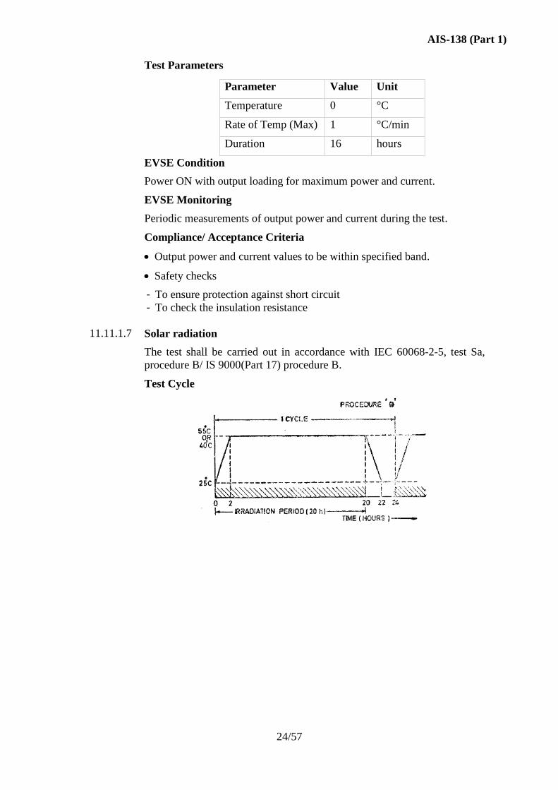
11.11.1.7 Solar radiation
The test shall be carried out in accordance with IEC 60068-2-5, test Sa,
procedure B/ IS 9000(Part 17) procedure B.
Test Cycle
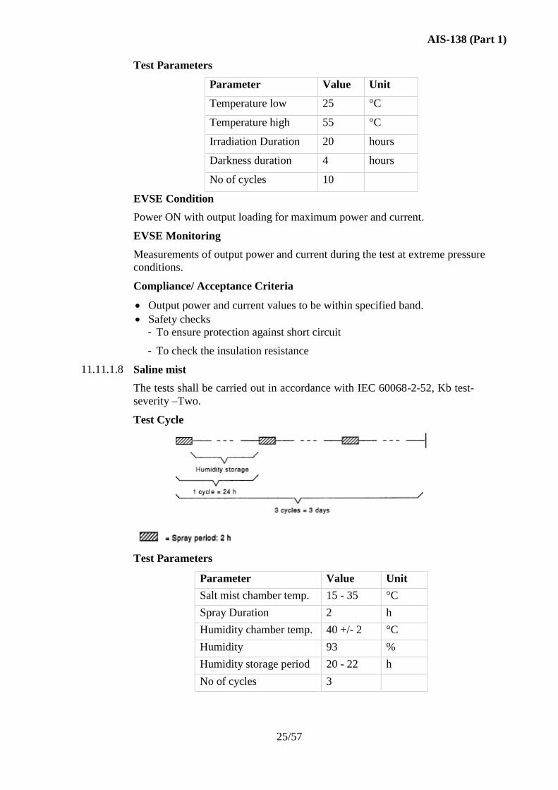
AIS-138 (Part 1)
25/57
Test Parameters
Parameter Value Unit
Temperature low 25 °C
Temperature high 55 °C
Irradiation Duration 20 hours
Darkness duration 4 hours
No of cycles 10
EVSE Condition
Power ON with output loading for maximum power and current.
EVSE Monitoring
Measurements of output power and current during the test at extreme pressure
conditions.
Compliance/ Acceptance Criteria
Output power and current values to be within specified band.
Safety checks
- To ensure protection against short circuit
- To check the insulation resistance
11.11.1.8 Saline mist
The tests shall be carried out in accordance with IEC 60068-2-52, Kb test-
severity –Two.
Test Cycle
Test Parameters
Parameter Value Unit
Salt mist chamber temp. 15 - 35 °C
Spray Duration 2 h
Humidity chamber temp. 40 +/- 2 °C
Humidity 93 %
Humidity storage period 20 - 22 h
No of cycles 3
AIS-138 (Part 1)
26/57
EVSE Condition
Power ON with output loading for maximum power and current.
EVSE Monitoring
Measurements of output power and current during the test at extreme pressure
conditions.
Compliance/ Acceptance Criteria
Insulation Resistance test to be performed immediately within 1 min after
damp heat.
Output power and current values to be within specified band.
Safety checks to ensure protection against short circuit.
11.11.2 Mechanical environmental tests
11.11.2.1 General
After the following tests, no degradation of performance is permitted.
Compliance is checked by verification after the test that
1) the IP degree is not affected;
2) the operation of the doors and locking points is not impaired;
3) the electrical clearances have remained satisfactory for the duration of the
tests, and
4) for a charging station having a metallic enclosure, no contact between live
parts and the enclosure has occurred, caused by permanent or temporary
distortion.
For a charging station having an enclosure of insulating material, if the
conditions above are satisfied, then damage such as small dents or small
degrees of surface cracking or flaking are disregarded, provided that there are
no associated cracks detrimental to the serviceability of the charging station.
11.11.2.2 Mechanical impact
The EVSE – AC body shall not be damaged by mechanical impact.
Compliance is checked according to the test procedure described in IEC
60068-2-75 (severity) / IS 9000(Part 7/Sec 7) impact energy value 20 J (5 kg
at 0.4 m).
11.11.2.3 Stability
The EVSE - AC shall be installed as intended by the manufacturer's
installation instructions. A force of 500 N shall be applied for 5 min in the
horizontal direction to the top of the EVSE - AC in each of the four directions
or in the worst possible horizontal direction. There shall be neither
deterioration of the a.c. Electric vehicle charging neither station nor
deformation at its summit greater than
50 mm during the load application;
10 mm alter the load application.
AIS-138 (Part 1)
27/57
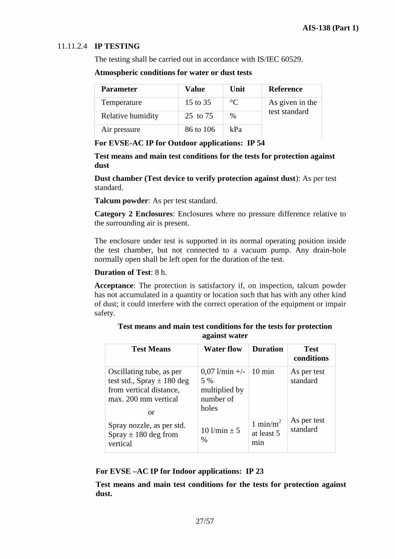
11.11.2.4 IP TESTING
The testing shall be carried out in accordance with IS/IEC 60529.
Atmospheric conditions for water or dust tests
Parameter Value Unit Reference
Temperature 15 to 35 °C As given in the
test standard Relative humidity 25 to 75 %
Air pressure 86 to 106 kPa
For EVSE-AC IP for Outdoor applications: IP 54
Test means and main test conditions for the tests for protection against
dust
Dust chamber (Test device to verify protection against dust): As per test
standard.
Talcum powder: As per test standard.
Category 2 Enclosures: Enclosures where no pressure difference relative to
the surrounding air is present.
The enclosure under test is supported in its normal operating position inside
the test chamber, but not connected to a vacuum pump. Any drain-hole
normally open shall be left open for the duration of the test.
Duration of Test: 8 h.
Acceptance: The protection is satisfactory if, on inspection, talcum powder
has not accumulated in a quantity or location such that has with any other kind
of dust; it could interfere with the correct operation of the equipment or impair
safety.
Test means and main test conditions for the tests for protection
against water
Test Means Water flow Duration Test
conditions
Oscillating tube, as per
test std., Spray ± 180 deg
from vertical distance,
max. 200 mm vertical
or
Spray nozzle, as per std.
Spray ± 180 deg from
vertical
0,07 l/min +/-
5 %
multiplied by
number of
holes
10 l/min ± 5
%
10 min
1 min/m2
at least 5
min
As per test
standard
As per test
standard
For EVSE –AC IP for Indoor applications: IP 23
Test means and main test conditions for the tests for protection against
dust.
AIS-138 (Part 1)
28/57
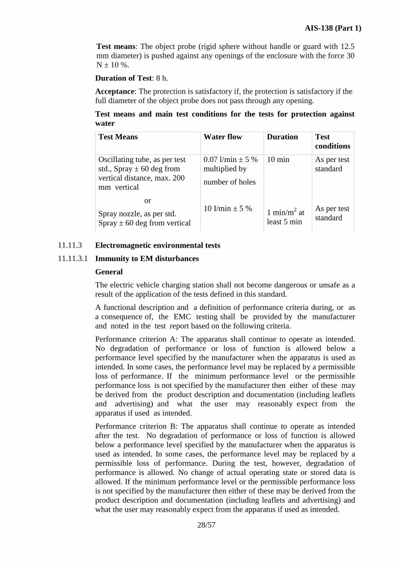
Test means: The object probe (rigid sphere without handle or guard with 12.5
mm diameter) is pushed against any openings of the enclosure with the force 30
N ± 10 %.
Duration of Test: 8 h.
Acceptance: The protection is satisfactory if, the protection is satisfactory if the
full diameter of the object probe does not pass through any opening.
Test means and main test conditions for the tests for protection against
water
Test Means Water flow Duration Test
conditions
Oscillating tube, as per test
std., Spray ± 60 deg from
vertical distance, max. 200
mm vertical
or
Spray nozzle, as per std.
Spray ± 60 deg from vertical
0.07 l/min ± 5 %
multiplied by
number of holes
10 I/min ± 5 %
10 min
1 min/m2 at
least 5 min
As per test
standard
As per test
standard
11.11.3
Electromagnetic environmental tests
11.11.3.1 Immunity to EM disturbances
General
The electric vehicle charging station shall not become dangerous or unsafe as a
result of the application of the tests defined in this standard.
A functional description and a definition of performance criteria during, or as
a consequence of, the EMC testing shall be provided by the manufacturer
and noted in the test report based on the following criteria.
Performance criterion A: The apparatus shall continue to operate as intended.
No degradation of performance or loss of function is allowed below a
performance level specified by the manufacturer when the apparatus is used as
intended. In some cases, the performance level may be replaced by a permissible
loss of performance. If the minimum performance level or the permissible
performance loss is not specified by the manufacturer then either of these may
be derived from the product description and documentation (including leaflets
and advertising) and what the user may reasonably expect from the
apparatus if used as intended.
Performance criterion B: The apparatus shall continue to operate as intended
after the test. No degradation of performance or loss of function is allowed
below a performance level specified by the manufacturer when the apparatus is
used as intended. In some cases, the performance level may be replaced by a
permissible loss of performance. During the test, however, degradation of
performance is allowed. No change of actual operating state or stored data is
allowed. If the minimum performance level or the permissible performance loss
is not specified by the manufacturer then either of these may be derived from the
product description and documentation (including leaflets and advertising) and
what the user may reasonably expect from the apparatus if used as intended.
AIS-138 (Part 1)
29/57
Performance criterion C: Temporary loss of function is allowed, provided the
loss of function can be restored by operation of the controls.
In any case, safety functions and metering shall be maintained (level A).
11.11.3.2 Immunity to electrostatic discharges
The EVSE – AC shall withstand electrostatic discharges.
Minimal requirement (IEC 61000-4-2) / IS 14700 (Part 4/See 2): 8 kV (in air
discharge) or 4 kV (contact discharge).
Performance criterion: B.
Compliance is checked according to IEC 61000-4-2/ IS 14700 (Part 4/See 2). In
the standard, the contact discharge method is mandatory. Tests shall be carried
out with the EVSE - AC connected to a resistive load at its rated output power.
Immunity to low-frequency conducted disturbances
Tests shall be carried out with the EVSE - AC connected to a resistive load at its
rated output power.
a) Supply voltage harmonics
The EVSE – AC, powered by the a.c. supply network (mains), shall
withstand the voltage harmonics of the main supply, in the frequency range
50 Hz - 2 kHz, generally caused by other non-linear loads connected to the
a.c. supply network.
Minimum requirement: compatibility levels of IEC 61000-2-2 multiplied
by a factor of 1, 7. Performance criteria: A for charging functions.
Compliance is checked by simulating the above conditions (IEC 61000-4-1/
IS 14700 (Part 4/sec 1)).
b) Supply voltage dips and interruptions
The EVSE - AC, powered by the a.c. supply network (mains), shall
withstand the voltage dips and interruptions of the a.c. supply, generally
caused by faults on the a.c. supply network.
Minimum requirement: voltage reduction of 30 % of nominal voltage for
10 ms. Performance criterion: B for charging functions.
Minimum requirement: voltage reduction of 50% for 100 ms.
Performance criterion: B for charging functions.
Minimum requirement: voltage reduction >95% for 5 s.
Performance criterion: B for charging functions.
Compliance is checked by simulating the above conditions (see IEC
61000-4-11/ IS 14700 (Part 4/ sec 11)).
c) Immunity to voltage unbalance
The EVSE - AC, powered by a three-phase a.c. supply (mains), shall
withstand voltage unbalance of the a.c. supply.
Minimum requirement: under consideration.
Performance criteria: under consideration.
AIS-138 (Part 1)
30/57
d) DC component
The EVSE - AC, powered by the a.c. supply network (mains), shall
withstand the d.c. components, generally caused by asymmetrical loads.
Minimal requirement: under consideration.
Performance criteria: under consideration.
Immunity to high-frequency conducted disturbances
Tests shall be carried out with the EVSE – AC connected to a resistive load at its
rated output power.
a) Fast transient bursts
The EVSE - AC, powered by the a.c. supply network (mains), shall
withstand common-mode conducted disturbances to levels given in IEC
61000-4-4/ IS 14700 (Part 4/Set 4), generally caused by the switching of
small inductive loads, relay contacts bouncing, or switching of high-voltage
switchgear.
Minimal requirement (IEC 61000-4-4/ IS 14700 (Part 4/Set 4): 2 kV, for a
time greater than 1 min and a repetition rate of the impulses of 5 kHz.
Performance criterion: B for charging functions.
Compliance is checked by tests according to IEC 61000-4-4/ IS 14700 (Part
4/Set 4).
The tests shall be made on all power cables and on 1/0 signal and control
cables, if any, normally connected to EVSE - AC during the charge. For 1/0
signal and control cables the voltage level is divided by two.
b) Voltage surges
The EVSE - AC, powered by the a.c. supply network (mains), shall
withstand the voltage surges, generally caused by switching phenomena in
the power a.c. supply network, faults or lightning strokes (indirect
strokes).
Minimal requirement: 1.2/50 uS surges, 2 kV in common mode, 1 kV in
differential mode. Performance criteria: C for charging functions.
Compliance is checked by tests according to IEC 61000-4-5.
The tests shall be made on all power cables. Tests shall be carried out
with the EVSE - AC connected to a resistive load at rated output power.
Immunity to radiated electromagnetic disturbances
The EVSE - AC shall withstand radiated electromagnetic disturbances.
Minimal requirement (IEC 61000-4-3): 3 V/m in the frequency range 80 MHz to
1000 MHz.
Performance criterion: A.
Minimal requirement (IEC 61000-4-3): 10 V/m in the frequency range 80 MHz
to 1000 MHz.
AIS-138 (Part 1)
31/57
Performance criterion: B.
Compliance is checked by tests according to IEC 61000-4-3.
Tests shall be carried out with the EVSE - AC connected to a resistive load
at rated output power.
11.11.3.3 Emitted EM disturbances
Low-frequency conducted disturbances
Input current distortion of the EVSE – AC shall not be excessive.
The harmonic limits for the input current of the EVSE - AC, with no load
connected, shall be in accordance with IEC 61000-3-2.
Compliance is checked according to IEC 61000-3-2.
High frequency conducted disturbances
a) AC input terminal
Conducted disturbances emitted at the input of the EVSE - AC, with a
resistive load at its rated output power, shall be less than the amplitude
of the level defined in Table 1.
Table 1 : Limit levels of conducted Interference AC supply Network
Frequency Range
(MHz)
Limits dB (uV)
Quasi –Peak Average
0,15 to 0,50 66 to 56 56 to 46
0,50 to 5 56 46
5 to 30 60 50
NOTE 1 - The lower limit shall apply at the transition frequencies.
NOTE 2 - The limit decreases linearly with the logarithm of the frequency in
the range 0,15 MHz to 0,50 MHz
Compliance is checked according to CISPR 22.
b) Signal I/0 and control terminals
Conducted disturbances emitted at signal I/0 and control terminals, if any,
shall be less than the amplitude of the level defined in Table 2, using a
quasi-peak detector.
AIS-138 (Part 1)
32/57
Table 2 : Conducted Interference signal I/O and control
Frequency Range
(MHz)
Limits dB (uV)
Quasi –Peak Average
0,15 to 0,50 40 to 30 30 to 20
0,5 to 30 30 20
NOTE 1 - The limits decrease linearly with the logarithm of the frequency in
the range 0,15 MHz to 0,5 MHz.
Compliance is checked according to CISPR 22.
Radiated electromagnetic disturbances
a) Magnetic field (150 kHz- 30 MHz)
Under consideration.
b) Electrical field (30 MHz- 1000 MHz)
Radiated disturbances by the EVSE-AC at 10 m, operating with a
resistive load at its rated output power, shall not exceed the limits given in
Table 3, using a quasi-peak detector.
Table 3 : Limit Levels of radiated emissions – enclosure at a measuring
distance of 10m
Frequency range (MHz) Radiated Interference (dBuV/m)
30 to 230 30
230 to 1000 37
NOTE 1 - The lower limit shall apply at the transition frequency.
NOTE 2 - Additional provisions may be required for cases where interference
occurs.
Compliance is checked according to CISPR 22.
11.12 Latching of the retaining device
An interlock may rely on the retaining device to avoid disconnection under load
if this function is not provided by the connector.
11.13 Service
The socket-outlet should be designed so that a certified technician could
remove, service and replace it if is necessary.
11.14 Marking and instructions
11.14.1 Connection instructions
Instructions for the connection of the electric vehicle to the EVSE - AC
shall be provided with the vehicle, with the user's manual and on the
EVSE – AC.
AIS-138 (Part 1)
33/57
11.14.2 Legibility
The markings required by this standard shall be legible with corrected vision,
durable and visible during use.
Compliance is checked by inspection and by rubbing the marking by hand
for 15 s with a piece of cloth soaked with water and again for 15 s with a
piece of cloth soaked with petroleum spirit.
After all the tests of this standard, the marking shall be easily legible; it
shall not be easily possible to remove marking plates and they shall show
no curling.
11.14.3 Marking of EVSE – AC
The station shall bear the following markings in a clear manner:
- Name or initials of manufacturer;
- Equipment reference;
- Serial number;
- Date of manufacture; rated voltage in V; rated frequency in Hz; rated
current in A; number of phases;
- IP degrees;
- "Indoor Use Only", or the equivalent, if intended for indoor use only;
- Class of EV depending on Load Capacity (Annex E)
For a Class II station, the symbol shall clearly appear in the markings;
Some minimal additional information can possibly appear on the station
itself (phone number, address of contractor).
Compliance is checked by inspection and tests.
11.15 Telecommunication network
Tests on any telecommunication network or telecommunication port on the
EVSE, if present, shall comply with IEC 60950-1.
AIS-138 (Part 1)
34/57
ANNEX A:
Pilot function through a control pilot circuit using PWM modulation and a control
pilot wire (Normative)
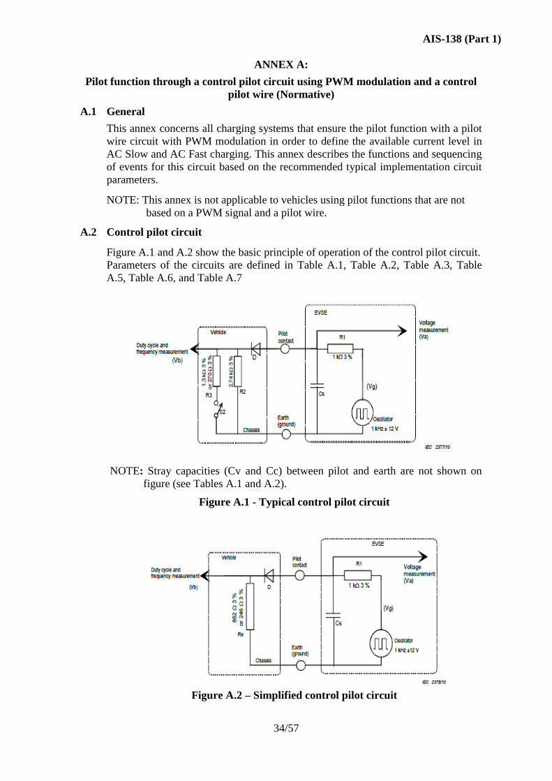
A.1 General
This annex concerns all charging systems that ensure the pilot function with a pilot
wire circuit with PWM modulation in order to define the available current level in
AC Slow and AC Fast charging. This annex describes the functions and sequencing
of events for this circuit based on the recommended typical implementation circuit
parameters.
NOTE: This annex is not applicable to vehicles using pilot functions that are not
based on a PWM signal and a pilot wire.
A.2 Control pilot circuit
Figure A.1 and A.2 show the basic principle of operation of the control pilot circuit.
Parameters of the circuits are defined in Table A.1, Table A.2, Table A.3, Table
A.5, Table A.6, and Table A.7
NOTE: Stray capacities (Cv and Cc) between pilot and earth are not shown on
figure (see Tables A.1 and A.2).
Figure A.1 - Typical control pilot circuit
Figure A.2 – Simplified control pilot circuit
AIS-138 (Part 1)
35/57
The simplified circuit shall not be used for vehicles drawing more than 15 A single
phase. It shall not be used with 3-phase supply.
NOTE: This circuit gives an equivalent result to the circuit shown in Figure A.1
when the switch S2 is closed. The simplified control pilot circuit cannot
create vehicle states A and B as defined in Table A.3.
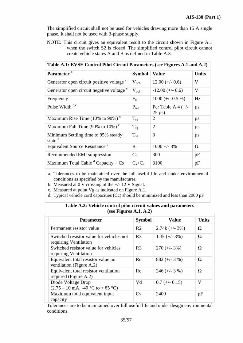
Table A.1: EVSE Control Pilot Circuit Parameters (see Figures A.1 and A.2)
Parameter a Symbol Value Units
Generator open circuit positive voltage c Voch 12.00 (+/- 0.6) V
Generator open circuit negative voltage c Vocl -12.00 (+/- 0.6) V
Frequency Fo 1000 (+/- 0.5 %) Hz
Pulse Width b,c
Pwo Per Table A.4 (+/-
25 µs)
µs
Maximum Rise Time (10% to 90%) c Trg 2 µs
Maximum Fall Time (90% to 10%) c Tfg 2 µs
Minimum Settling time to 95% steady
state c
Tsg 3 µs
Equivalent Source Resistance c R1 1000 +/- 3% Ω
Recommended EMI suppression Cs 300 pF
Maximum Total Cable d Capacity + Cs Cs+Cc 3100 pF
a. Tolerances to be maintained over the full useful life and under environmental
conditions as specified by the manufacturer.
b. Measured at 0 V crossing of the +/- 12 V Signal.
c. Measured at point Vg as indicated on Figure A.1.
d. Typical vehicle cord capacities (Cc) should be minimized and less than 2000 pF
Table A.2: Vehicle control pilot circuit values and parameters
(see Figures A.1, A.2)
Parameter Symbol Value Units
Permanent resistor value R2 2.74k (+/- 3%) Ω
Switched resistor value for vehicles not
requiring Ventilation
R3 1.3k (+/- 3%) Ω
Switched resistor value for vehicles
requiring Ventilation
R3 270 (+/- 3%) Ω
Equivalent total resistor value no
ventilation (Figure A.2)
Re 882 (+/- 3 %) Ω
Equivalent total resistor ventilation
required (Figure A.2)
Re 246 (+/- 3 %) Ω
Diode Voltage Drop
(2.75 – 10 mA, -40 °C to + 85 °C)
Vd 0.7 (+/- 0.15) V
Maximum total equivalent input
capacity
Cv 2400 pF
Tolerances are to be maintained over full useful life and under design environmental
conditions.
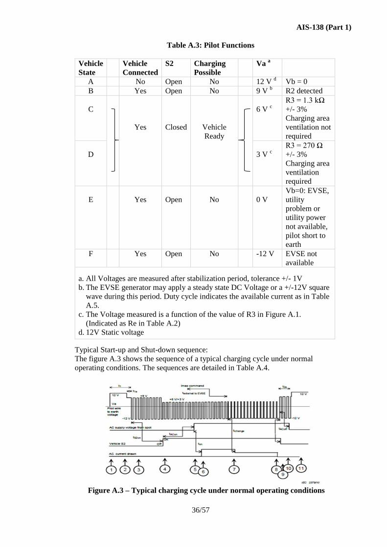
AIS-138 (Part 1)
36/57
Table A.3: Pilot Functions
Vehicle
State
Vehicle
Connected
S2 Charging
Possible
Va a
A No Open No 12 V d Vb = 0
B Yes Open No 9 V b R2 detected
C
Yes
Closed
Vehicle
Ready
6 V c
R3 = 1.3 kΩ
+/- 3%
Charging area
ventilation not
required
D
3 V c
R3 = 270 Ω
+/- 3%
Charging area
ventilation
required
E
Yes
Open
No
0 V
Vb=0: EVSE,
utility
problem or
utility power
not available,
pilot short to
earth
F Yes Open No -12 V EVSE not
available
a. All Voltages are measured after stabilization period, tolerance +/- 1V
b. The EVSE generator may apply a steady state DC Voltage or a +/-12V square
wave during this period. Duty cycle indicates the available current as in Table
A.5.
c. The Voltage measured is a function of the value of R3 in Figure A.1.
(Indicated as Re in Table A.2)
d. 12V Static voltage
Typical Start-up and Shut-down sequence:
The figure A.3 shows the sequence of a typical charging cycle under normal
operating conditions. The sequences are detailed in Table A.4.
Figure A.3 – Typical charging cycle under normal operating conditions
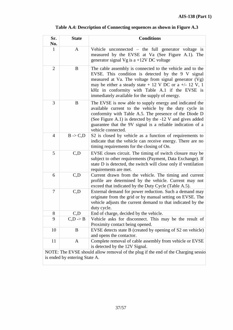
AIS-138 (Part 1)
37/57
Table A.4: Description of Connecting sequences as shown in Figure A.3
Sr.
No.
State Conditions
1 A
Vehicle unconnected – the full generator voltage is
measured by the EVSE at Va (See Figure A.1). The
generator signal Vg is a +12V DC voltage
2 B The cable assembly is connected to the vehicle and to the
EVSE. This condition is detected by the 9 V signal
measured at Va. The voltage from signal generator (Vg)
may be either a steady state + 12 V DC or a +/- 12 V, 1
kHz in conformity with Table A.1 if the EVSE is
immediately available for the supply of energy.
3 B The EVSE is now able to supply energy and indicated the
available current to the vehicle by the duty cycle in
conformity with Table A.5. The presence of the Diode D
(See Figure A.1) is detected by the -12 V and gives added
guarantee that the 9V signal is a reliable indication of a
vehicle connected.
4 B -> C,D S2 is closed by vehicle as a function of requirements to
indicate that the vehicle can receive energy. There are no
timing requirements for the closing of On.
5 C,D EVSE closes circuit. The timing of switch closure may be
subject to other requirements (Payment, Data Exchange). If
state D is detected, the switch will close only if ventilation
requirements are met.
6 C,D Current drawn from the vehicle. The timing and current
profile are determined by the vehicle. Current may not
exceed that indicated by the Duty Cycle (Table A.5).
7 C,D External demand for power reduction. Such a demand may
originate from the grid or by manual setting on EVSE. The
vehicle adjusts the current demand to that indicated by the
duty cycle.
8 C,D End of charge, decided by the vehicle.
9 C,D -> B Vehicle asks for disconnect. This may be the result of
Proximity contact being opened.
10 B EVSE detects state B (created by opening of S2 on vehicle)
and opens the contactor.
11 A Complete removal of cable assembly from vehicle or EVSE
is detected by the 12V Signal.
NOTE: The EVSE should allow removal of the plug if the end of the Charging session
is ended by entering State A.
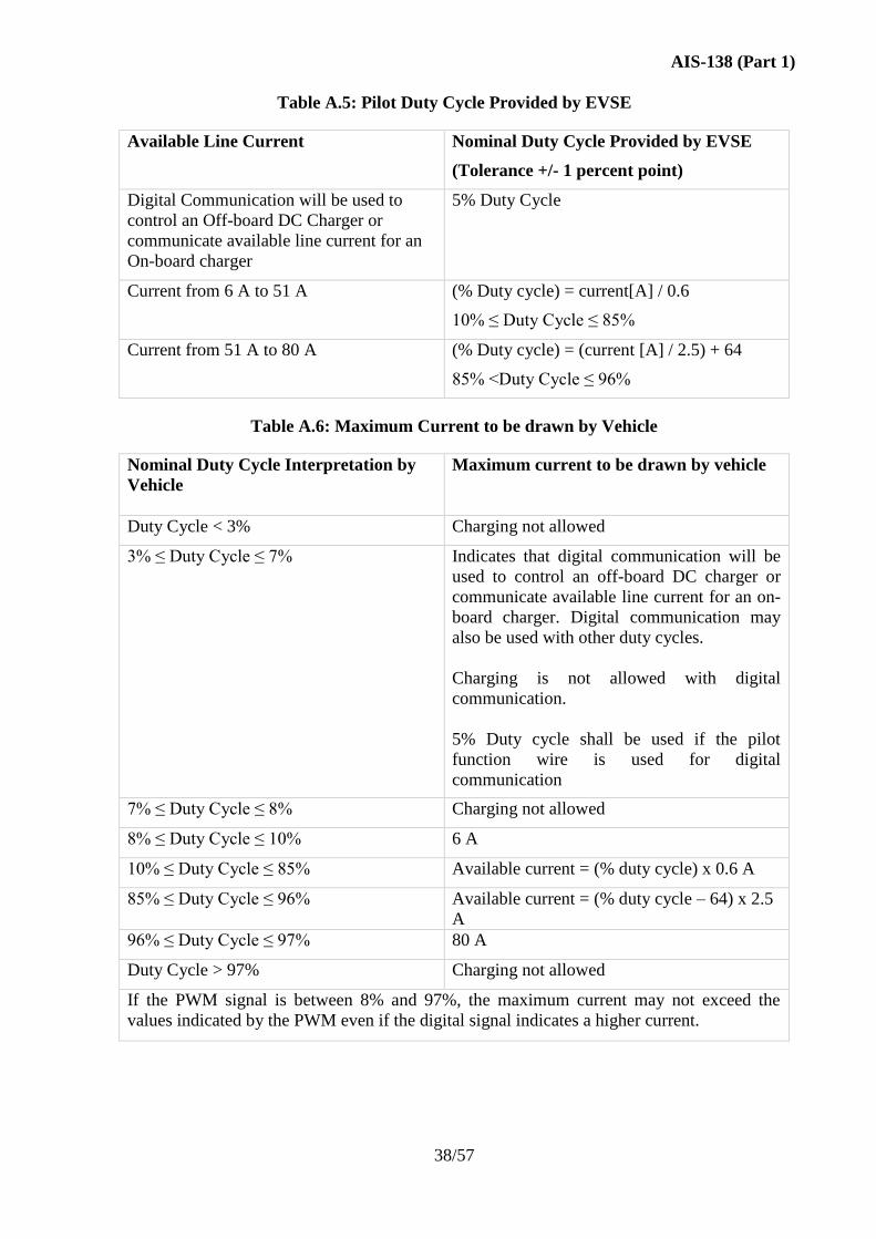
AIS-138 (Part 1)
38/57
Table A.5: Pilot Duty Cycle Provided by EVSE
Available Line Current Nominal Duty Cycle Provided by EVSE
(Tolerance +/- 1 percent point)
Digital Communication will be used to
control an Off-board DC Charger or
communicate available line current for an
On-board charger
5% Duty Cycle
Current from 6 A to 51 A (% Duty cycle) = current[A] / 0.6
10% ≤ Duty Cycle ≤ 85%
Current from 51 A to 80 A (% Duty cycle) = (current [A] / 2.5) + 64
85% <Duty Cycle ≤ 96%
Table A.6: Maximum Current to be drawn by Vehicle
Nominal Duty Cycle Interpretation by
Vehicle
Maximum current to be drawn by vehicle
Duty Cycle < 3% Charging not allowed
3% ≤ Duty Cycle ≤ 7% Indicates that digital communication will be
used to control an off-board DC charger or
communicate available line current for an on-
board charger. Digital communication may
also be used with other duty cycles.
Charging is not allowed with digital
communication.
5% Duty cycle shall be used if the pilot
function wire is used for digital
communication
7% ≤ Duty Cycle ≤ 8% Charging not allowed
8% ≤ Duty Cycle ≤ 10% 6 A
10% ≤ Duty Cycle ≤ 85% Available current = (% duty cycle) x 0.6 A
85% ≤ Duty Cycle ≤ 96% Available current = (% duty cycle – 64) x 2.5
A
96% ≤ Duty Cycle ≤ 97% 80 A
Duty Cycle > 97% Charging not allowed
If the PWM signal is between 8% and 97%, the maximum current may not exceed the
values indicated by the PWM even if the digital signal indicates a higher current.
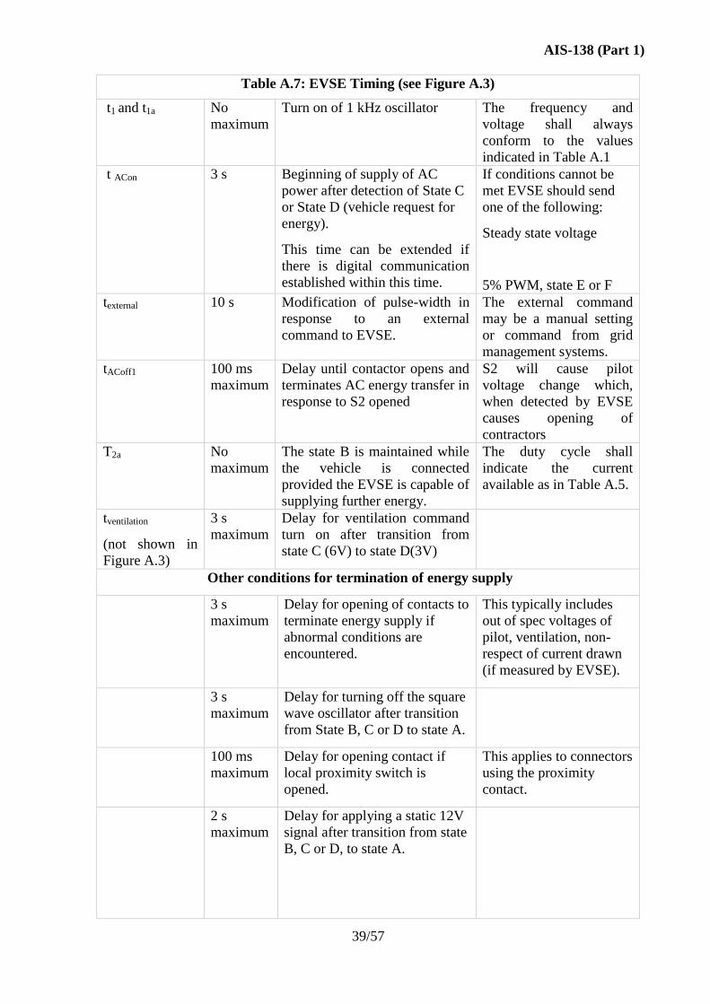
AIS-138 (Part 1)
39/57
Table A.7: EVSE Timing (see Figure A.3)
t1 and t1a No
maximum
Turn on of 1 kHz oscillator The frequency and
voltage shall always
conform to the values
indicated in Table A.1
t ACon 3 s Beginning of supply of AC
power after detection of State C
or State D (vehicle request for
energy).
This time can be extended if
there is digital communication
established within this time.
If conditions cannot be
met EVSE should send
one of the following:
Steady state voltage
5% PWM, state E or F
texternal 10 s Modification of pulse-width in
response to an external
command to EVSE.
The external command
may be a manual setting
or command from grid
management systems.
tACoff1 100 ms
maximum
Delay until contactor opens and
terminates AC energy transfer in
response to S2 opened
S2 will cause pilot
voltage change which,
when detected by EVSE
causes opening of
contractors
T2a No
maximum
The state B is maintained while
the vehicle is connected
provided the EVSE is capable of
supplying further energy.
The duty cycle shall
indicate the current
available as in Table A.5.
tventilation
(not shown in
Figure A.3)
3 s
maximum
Delay for ventilation command
turn on after transition from
state C (6V) to state D(3V)
Other conditions for termination of energy supply
3 s
maximum
Delay for opening of contacts to
terminate energy supply if
abnormal conditions are
encountered.
This typically includes
out of spec voltages of
pilot, ventilation, non-
respect of current drawn
(if measured by EVSE).
3 s
maximum
Delay for turning off the square
wave oscillator after transition
from State B, C or D to state A.
100 ms
maximum
Delay for opening contact if
local proximity switch is
opened.
This applies to connectors
using the proximity
contact.
2 s
maximum
Delay for applying a static 12V
signal after transition from state
B, C or D, to state A.
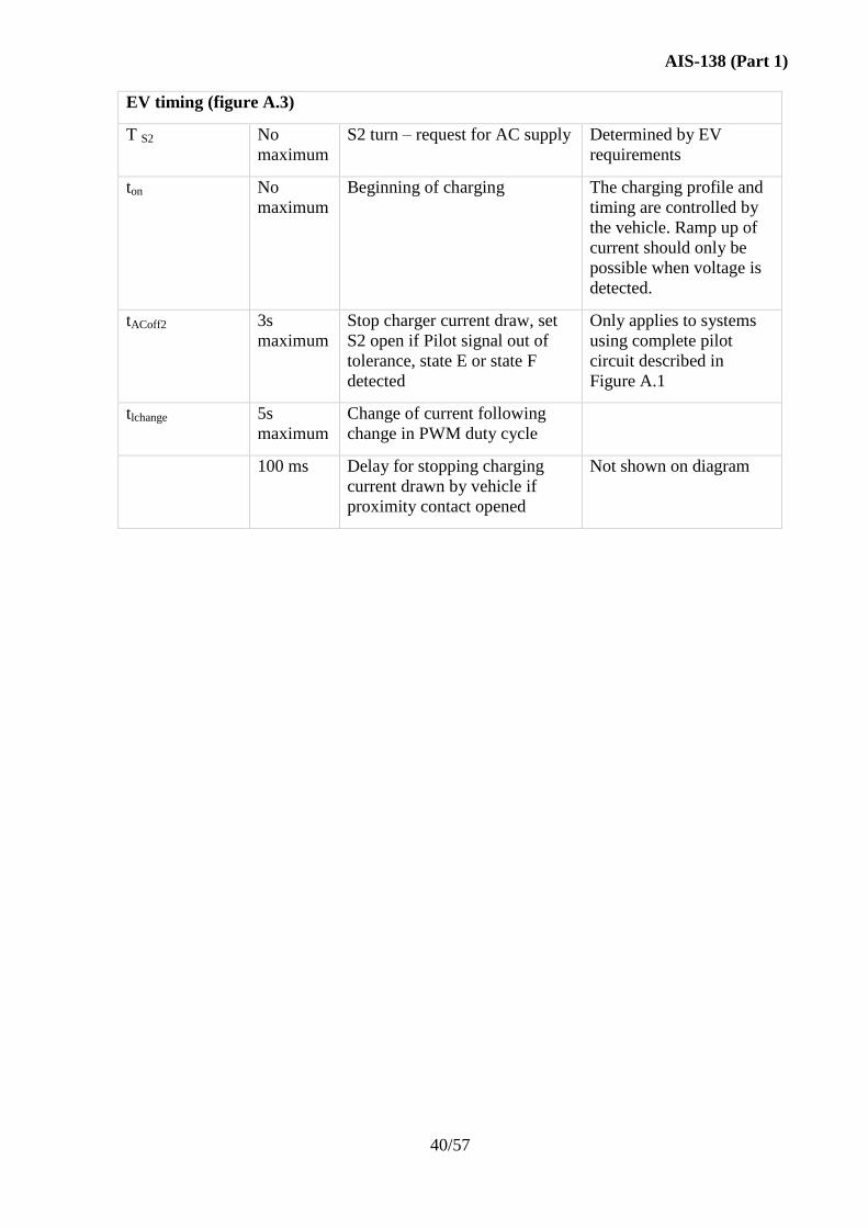
AIS-138 (Part 1)
40/57
EV timing (figure A.3)
T S2 No
maximum
S2 turn – request for AC supply Determined by EV
requirements
ton No
maximum
Beginning of charging The charging profile and
timing are controlled by
the vehicle. Ramp up of
current should only be
possible when voltage is
detected.
tACoff2 3s
maximum
Stop charger current draw, set
S2 open if Pilot signal out of
tolerance, state E or state F
detected
Only applies to systems
using complete pilot
circuit described in
Figure A.1
tlchange 5s
maximum
Change of current following
change in PWM duty cycle
100 ms Delay for stopping charging
current drawn by vehicle if
proximity contact opened
Not shown on diagram
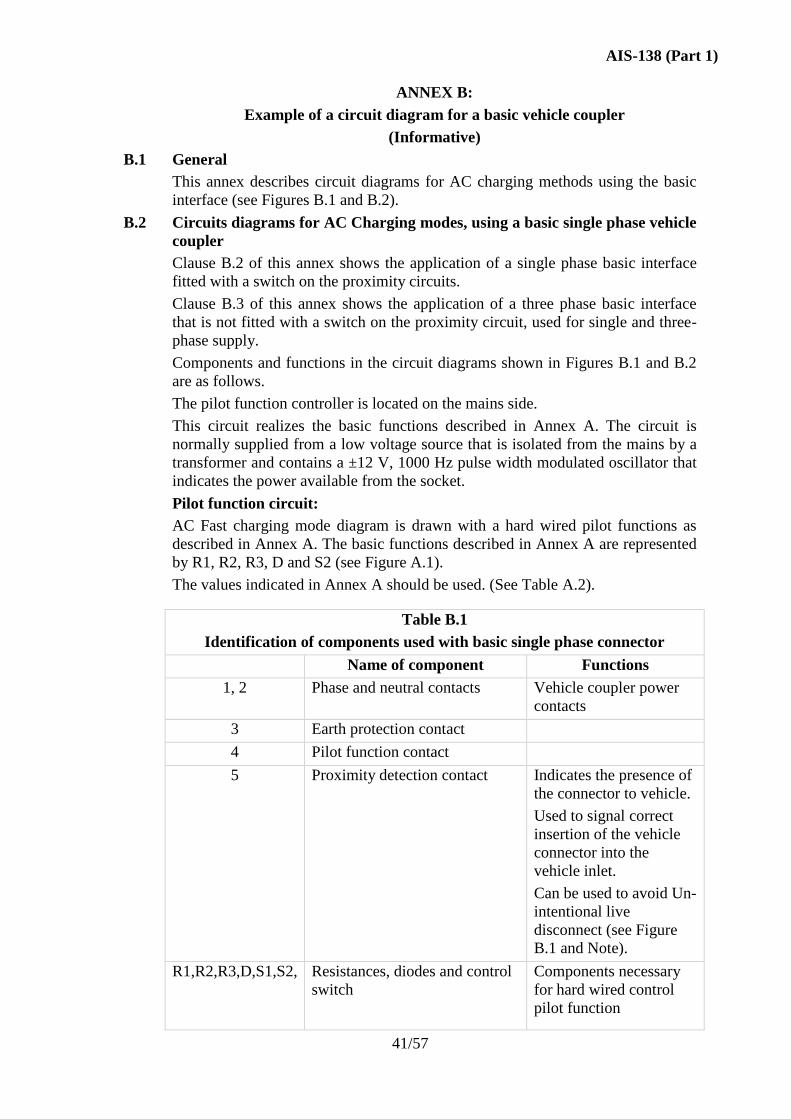
AIS-138 (Part 1)
41/57
ANNEX B:
Example of a circuit diagram for a basic vehicle coupler
(Informative)
B.1 General
This annex describes circuit diagrams for AC charging methods using the basic
interface (see Figures B.1 and B.2).
B.2 Circuits diagrams for AC Charging modes, using a basic single phase vehicle
coupler
Clause B.2 of this annex shows the application of a single phase basic interface
fitted with a switch on the proximity circuits.
Clause B.3 of this annex shows the application of a three phase basic interface
that is not fitted with a switch on the proximity circuit, used for single and three-
phase supply.
Components and functions in the circuit diagrams shown in Figures B.1 and B.2
are as follows.
The pilot function controller is located on the mains side.
This circuit realizes the basic functions described in Annex A. The circuit is
normally supplied from a low voltage source that is isolated from the mains by a
transformer and contains a ±12 V, 1000 Hz pulse width modulated oscillator that
indicates the power available from the socket.
Pilot function circuit:
AC Fast charging mode diagram is drawn with a hard wired pilot functions as
described in Annex A. The basic functions described in Annex A are represented
by R1, R2, R3, D and S2 (see Figure A.1).
The values indicated in Annex A should be used. (See Table A.2).
Table B.1
Identification of components used with basic single phase connector
Name of component Functions
1, 2 Phase and neutral contacts Vehicle coupler power
contacts
3 Earth protection contact
4 Pilot function contact
5 Proximity detection contact
Indicates the presence of
the connector to vehicle.
Used to signal correct
insertion of the vehicle
connector into the
vehicle inlet.
Can be used to avoid Un-
intentional live
disconnect (see Figure
B.1 and Note).
R1,R2,R3,D,S1,S2, Resistances, diodes and control
switch
Components necessary
for hard wired control
pilot function
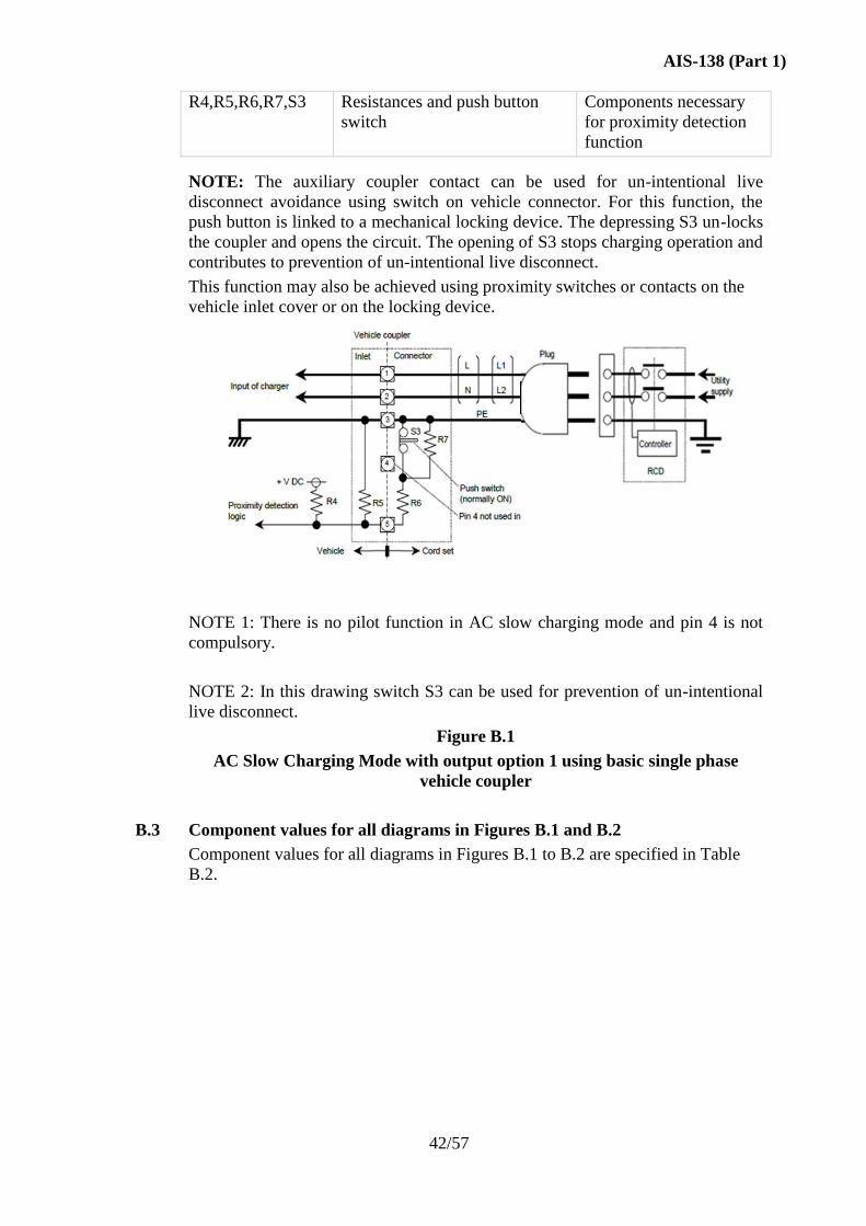
AIS-138 (Part 1)
42/57
R4,R5,R6,R7,S3 Resistances and push button
switch
Components necessary
for proximity detection
function
NOTE: The auxiliary coupler contact can be used for un-intentional live
disconnect avoidance using switch on vehicle connector. For this function, the
push button is linked to a mechanical locking device. The depressing S3 un-locks
the coupler and opens the circuit. The opening of S3 stops charging operation and
contributes to prevention of un-intentional live disconnect.
This function may also be achieved using proximity switches or contacts on the
vehicle inlet cover or on the locking device.
NOTE 1: There is no pilot function in AC slow charging mode and pin 4 is not
compulsory.
NOTE 2: In this drawing switch S3 can be used for prevention of un-intentional
live disconnect.
Figure B.1
AC Slow Charging Mode with output option 1 using basic single phase
vehicle coupler
B.3 Component values for all diagrams in Figures B.1 and B.2
Component values for all diagrams in Figures B.1 to B.2 are specified in Table
B.2.
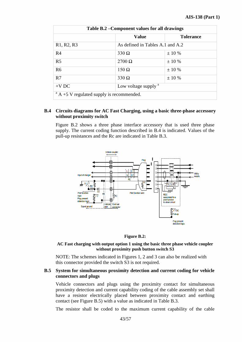
AIS-138 (Part 1)
43/57
Table B.2 –Component values for all drawings
Value Tolerance
R1, R2, R3 As defined in Tables A.1 and A.2
R4 330 Ω ± 10 %
R5 2700 Ω ± 10 %
R6 150 Ω ± 10 %
R7 330 Ω ± 10 %
+V DC Low voltage supply a
a A +5 V regulated supply is recommended.
B.4 Circuits diagrams for AC Fast Charging, using a basic three-phase accessory
without proximity switch
Figure B.2 shows a three phase interface accessory that is used three phase
supply. The current coding function described in B.4 is indicated. Values of the
pull-up resistances and the Rc are indicated in Table B.3.
Figure B.2:
AC Fast charging with output option 1 using the basic three phase vehicle coupler
without proximity push button switch S3
NOTE: The schemes indicated in Figures 1, 2 and 3 can also be realized with
this connector provided the switch S3 is not required.
B.5 System for simultaneous proximity detection and current coding for vehicle
connectors and plugs
Vehicle connectors and plugs using the proximity contact for simultaneous
proximity detection and current capability coding of the cable assembly set shall
have a resistor electrically placed between proximity contact and earthing
contact (see Figure B.5) with a value as indicated in Table B.3.
The resistor shall be coded to the maximum current capability of the cable
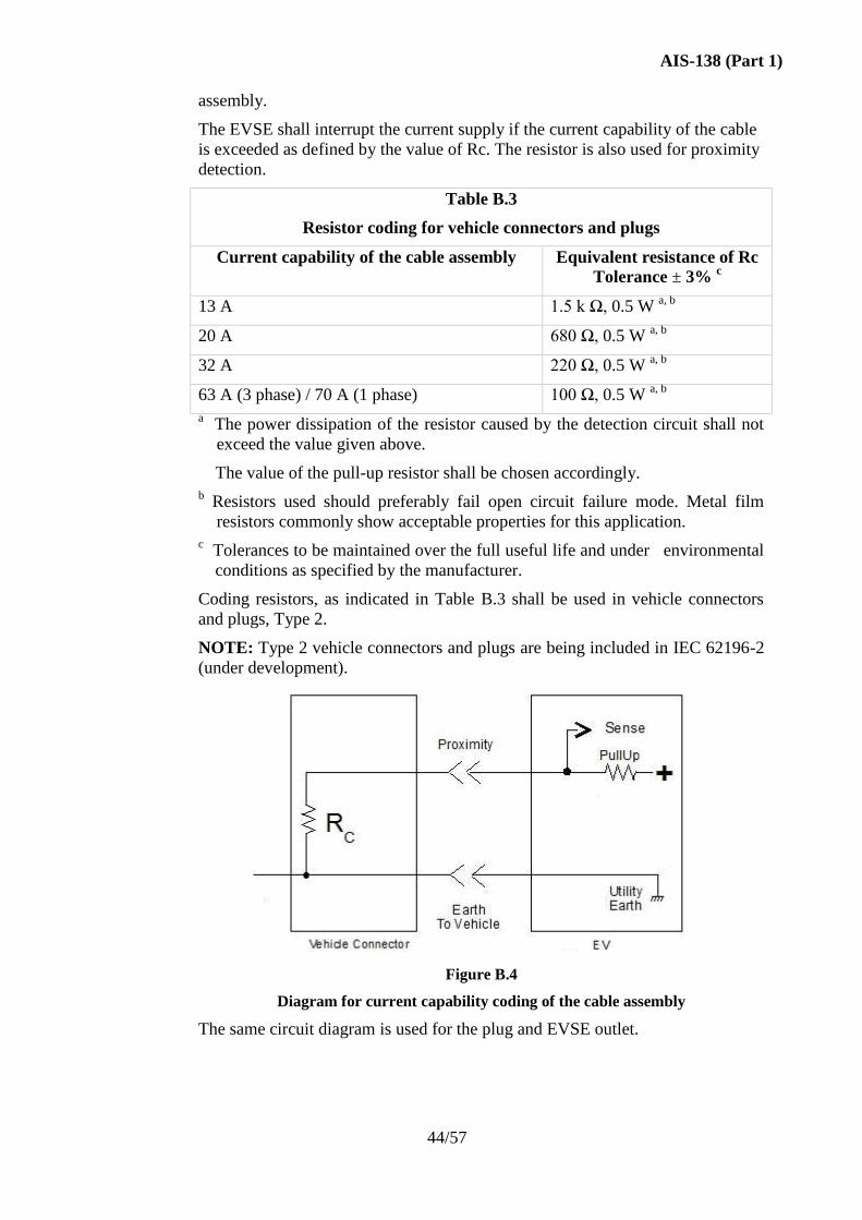
AIS-138 (Part 1)
44/57
assembly.
The EVSE shall interrupt the current supply if the current capability of the cable
is exceeded as defined by the value of Rc. The resistor is also used for proximity
detection.
Table B.3
Resistor coding for vehicle connectors and plugs
Current capability of the cable assembly Equivalent resistance of Rc
Tolerance ± 3% c
13 A 1.5 k Ω, 0.5 W a, b
20 A 680 Ω, 0.5 W a, b
32 A 220 Ω, 0.5 W a, b
63 A (3 phase) / 70 A (1 phase) 100 Ω, 0.5 W a, b
a The power dissipation of the resistor caused by the detection circuit shall not
exceed the value given above.
The value of the pull-up resistor shall be chosen accordingly.
b Resistors used should preferably fail open circuit failure mode. Metal film
resistors commonly show acceptable properties for this application.
c Tolerances to be maintained over the full useful life and under environmental
conditions as specified by the manufacturer.
Coding resistors, as indicated in Table B.3 shall be used in vehicle connectors
and plugs, Type 2.
NOTE: Type 2 vehicle connectors and plugs are being included in IEC 62196-2
(under development).
Figure B.4
Diagram for current capability coding of the cable assembly
The same circuit diagram is used for the plug and EVSE outlet.
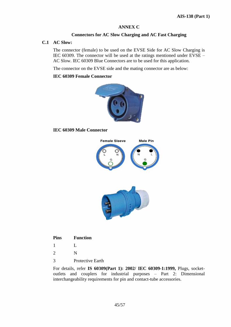
AIS-138 (Part 1)
45/57
ANNEX C
Connectors for AC Slow Charging and AC Fast Charging
C.1 AC Slow:
The connector (female) to be used on the EVSE Side for AC Slow Charging is
IEC 60309. The connector will be used at the ratings mentioned under EVSE –
AC Slow. IEC 60309 Blue Connectors are to be used for this application.
The connector on the EVSE side and the mating connector are as below:
IEC 60309 Female Connector
IEC 60309 Male Connector
Pins Function
1 L
2 N
3 Protective Earth
For details, refer IS 60309(Part 1): 2002/ IEC 60309-1:1999, Plugs, socket-
outlets and couplers for industrial purposes – Part 2: Dimensional
interchangeability requirements for pin and contact-tube accessories.
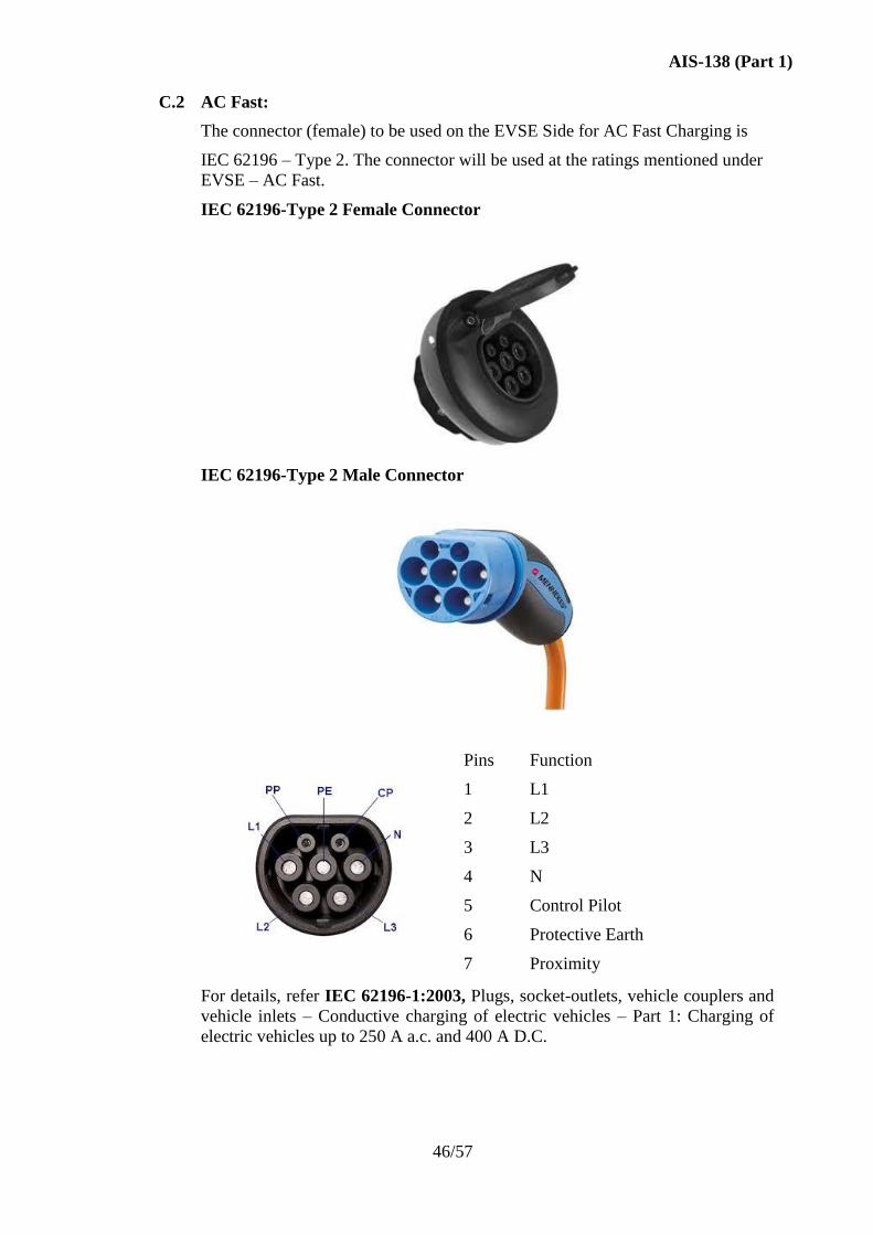
AIS-138 (Part 1)
46/57
C.2 AC Fast:
The connector (female) to be used on the EVSE Side for AC Fast Charging is
IEC 62196 – Type 2. The connector will be used at the ratings mentioned under
EVSE – AC Fast.
IEC 62196-Type 2 Female Connector
IEC 62196-Type 2 Male Connector
Pins Function
1 L1
2 L2
3 L3
4 N
5 Control Pilot
6 Protective Earth
7 Proximity
For details, refer IEC 62196-1:2003, Plugs, socket-outlets, vehicle couplers and
vehicle inlets – Conductive charging of electric vehicles – Part 1: Charging of
electric vehicles up to 250 A a.c. and 400 A D.C.
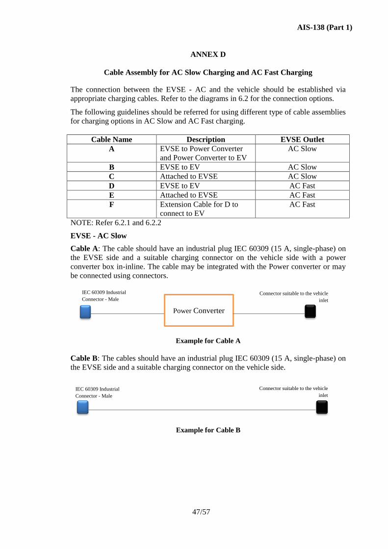
AIS-138 (Part 1)
47/57
ANNEX D
Cable Assembly for AC Slow Charging and AC Fast Charging
The connection between the EVSE - AC and the vehicle should be established via
appropriate charging cables. Refer to the diagrams in 6.2 for the connection options.
The following guidelines should be referred for using different type of cable assemblies
for charging options in AC Slow and AC Fast charging.
Cable Name Description EVSE Outlet
A EVSE to Power Converter
and Power Converter to EV
AC Slow
B EVSE to EV AC Slow
C Attached to EVSE AC Slow
D EVSE to EV AC Fast
E Attached to EVSE AC Fast
F Extension Cable for D to
connect to EV
AC Fast
NOTE: Refer 6.2.1 and 6.2.2
EVSE - AC Slow
Cable A: The cable should have an industrial plug IEC 60309 (15 A, single-phase) on
the EVSE side and a suitable charging connector on the vehicle side with a power
converter box in-inline. The cable may be integrated with the Power converter or may
be connected using connectors.
Example for Cable A
Cable B: The cables should have an industrial plug IEC 60309 (15 A, single-phase) on
the EVSE side and a suitable charging connector on the vehicle side.
Example for Cable B
Connector suitable to the vehicle
inlet
IEC 60309 Industrial
Connector - Male
Power Converter
Connector suitable to the vehicle
inlet
IEC 60309 Industrial
Connector - Male
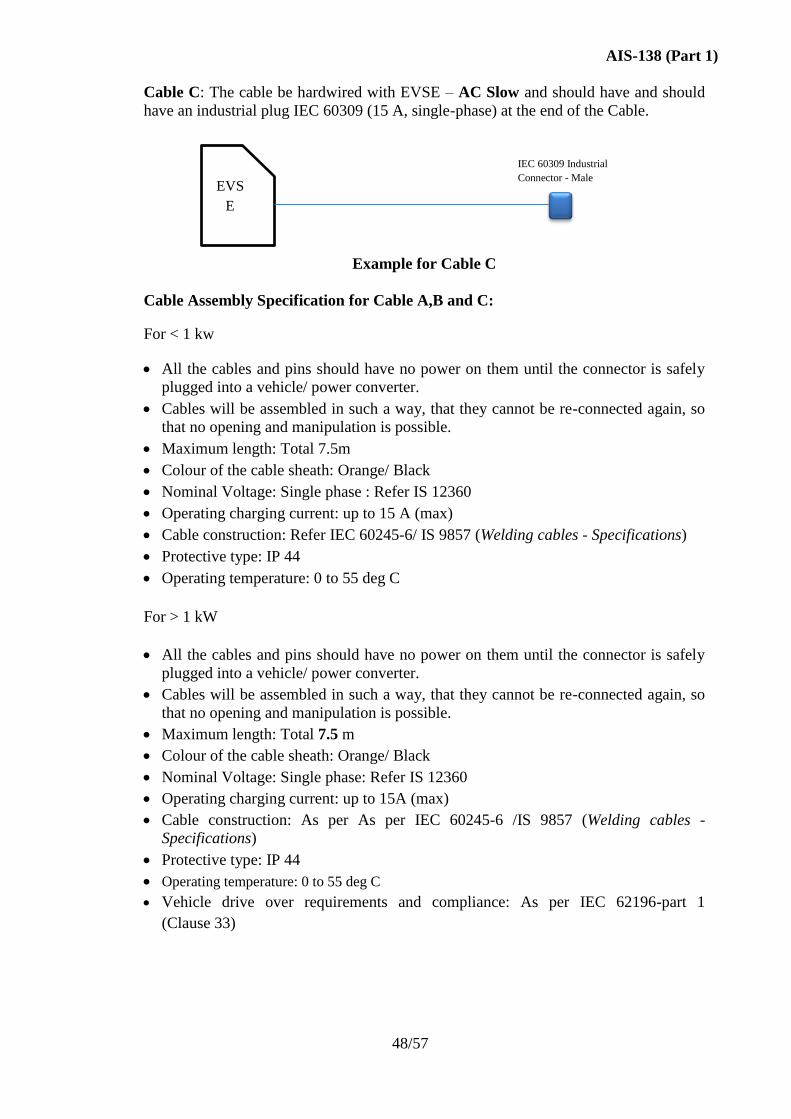
AIS-138 (Part 1)
48/57
Cable C: The cable be hardwired with EVSE – AC Slow and should have and should
have an industrial plug IEC 60309 (15 A, single-phase) at the end of the Cable.
Example for Cable C
Cable Assembly Specification for Cable A,B and C:
For < 1 kw
All the cables and pins should have no power on them until the connector is safely
plugged into a vehicle/ power converter.
Cables will be assembled in such a way, that they cannot be re-connected again, so
that no opening and manipulation is possible.
Maximum length: Total 7.5m
Colour of the cable sheath: Orange/ Black
Nominal Voltage: Single phase : Refer IS 12360
Operating charging current: up to 15 A (max)
Cable construction: Refer IEC 60245-6/ IS 9857 (Welding cables - Specifications)
Protective type: IP 44
Operating temperature: 0 to 55 deg C
For > 1 kW
All the cables and pins should have no power on them until the connector is safely
plugged into a vehicle/ power converter.
Cables will be assembled in such a way, that they cannot be re-connected again, so
that no opening and manipulation is possible.
Maximum length: Total 7.5 m
Colour of the cable sheath: Orange/ Black
Nominal Voltage: Single phase: Refer IS 12360
Operating charging current: up to 15A (max)
Cable construction: As per As per IEC 60245-6 /IS 9857 (Welding cables -
Specifications)
Protective type: IP 44
Operating temperature: 0 to 55 deg C
Vehicle drive over requirements and compliance: As per IEC 62196-part 1
(Clause 33)
EVS
E
IEC 60309 Industrial
Connector - Male

AIS-138 (Part 1)
49/57
Note: Refer IEC 60245-6 /IS 9857 for cable mechanical properties and testing
EVSE - AC Fast
Cable D: The cable should have an IEC 62196 type 2 plug (63A, three-phase 415V) on
the EVSE side and a suitable charging connector on the vehicle side.
Example for Cable D
Cable E: The cable be hardwired with EVSE – AC Fast and should have IEC 62196
type 2 socket (63A, three-phase 415V) on the other side.
Example for Cable E
Cable F: The cable should have an IEC 62196 type 2 plug (63A, three-phase 415V) on
one side and a suitable charging connector on the vehicle side.
Example for Cable F
Cable Assembly Specification for Cable C, D and E:
All the cables and pins should have no power on them until the connector is safely
plugged into a vehicle.
Cables will be assembled in such a way, that they cannot be re-connected again, so
that no opening and manipulation is possible.
Maximum length: C,D –7.5 m E – 1 m
Colour of the cable sheath: Orange/ Black
For Power Cables,
Rated Voltage: 415 V (Three phase)
Operating charging current: up to 63A (max)
Cable construction: As per IEC 60245-6/ IS 9857 (Welding cables -
Specifications)
IEC 62196 Type 2
Female Connector
Connector suitable to the vehicle
inlet
IEC 62196 Type 2 Male
Connector
EVSE
Connector suitable to the vehicle
inlet
IEC 62196 Type 2 Male
Connector
AIS-138 (Part 1)
50/57
Automatic charging current reduction at excessive heat
Nominal residual current: 30 mA
Protective type: IP 44
Operating temperature: 0 to 55o C
For Communication cables,
For the communication demands, typically two signal contacts and a hybrid-cable with
an additional 1 x 0.5 mm² conductor are required.
Rated Voltage: 30 V (Three phase)
Operating charging current: 2 A (max)
Cable size: 0.5 mm2 multicore copper/ aluminium equivalent
Vehicle drive over requirements and compliance: As per IEC 62196-part 1 (Clause
33)
Note: Refer IS 9857:1990: 1988/ IEC 60245-6 for cable mechanical properties and
testing.
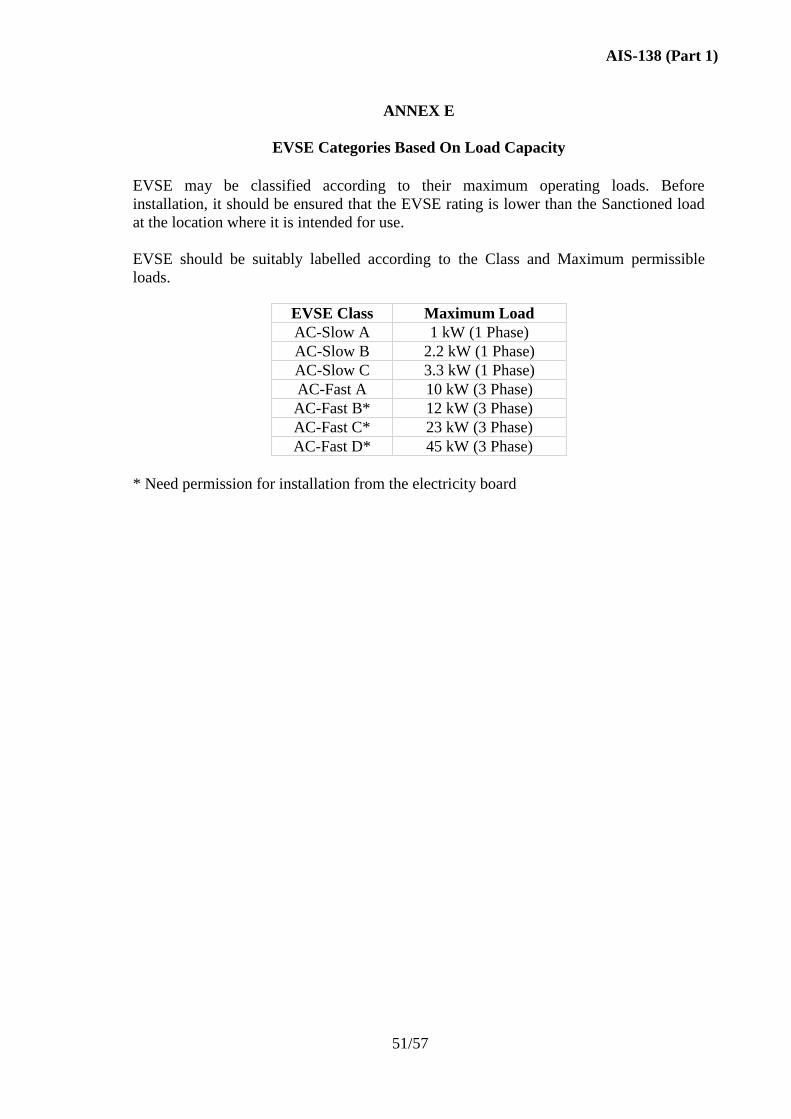
AIS-138 (Part 1)
51/57
ANNEX E
EVSE Categories Based On Load Capacity
EVSE may be classified according to their maximum operating loads. Before
installation, it should be ensured that the EVSE rating is lower than the Sanctioned load
at the location where it is intended for use.
EVSE should be suitably labelled according to the Class and Maximum permissible
loads.
EVSE Class Maximum Load
AC-Slow A 1 kW (1 Phase)
AC-Slow B 2.2 kW (1 Phase)
AC-Slow C 3.3 kW (1 Phase)
AC-Fast A 10 kW (3 Phase)
AC-Fast B* 12 kW (3 Phase)
AC-Fast C* 23 kW (3 Phase)
AC-Fast D* 45 kW (3 Phase)
* Need permission for installation from the electricity board
AIS-138 (Part 1)
52/57
ANNEX F
Power Converters (AC to DC)
A power converter is an AC - DC Converter to fulfil DC power requirements for charging
of electric vehicles. Power converter is required for the EVs which don’t have an on-
board charger. The power converter will be connected to EVSE - AC Slow in AC Slow
charging mode as shown in 6.2.1. For the necessary cable connections refer to Annex D.
The power converter should be rugged, simple to use, compact in size and water proof. It
should meet all necessary functional and safety requirements for charging of all supported
types of electric vehicles.
Recommended Features:
Input nominal voltage: single phase AC : Refer IS 12360
Input Frequency: 50 Hz
Maximum Rated Power : 1.1 kW
Output Voltage: DC Voltage range as suitable for the EV
Power ON indication
Fault indication
Mandatory safety features:
o Ground fault detection
o Output overload protection
o Output short circuit protection
o Output over voltage Protection
o Connector presence and locking
o Battery reverse protection
Power Factor >= 0.9
Environmental:
Operating temperature: 0 to 55oC
IP Rating: Same as EVSE - AC Slow
EMI compliance: Same as EVSE - AC Slow
Safety compliance: Same as EVSE - AC Slow
AIS-138 (Part 1)
53/57
ANNEX G
Periodic Compliance of EVSE
In addition to the conformity testing of the EVSE after manufacturing, the equipment
should be tested yearly during its operation to ensure that there is no lapse of Safety or
deterioration in functionality of the EVSE.
The EVSE must be assessed periodically for the following:
Generic Functional Verification: like VIN, Metering.
Mechanical conditions
1. Abrasion
2. Oxidation
3. Carbonization
4. Any other conditions which may lead to deterioration of functions or lead to lapse of
safety.
Electrical conditions
1. Isolation resistance
2. Functioning of RCD detection and Isolation mechanism
3. Compliance to Sanctioned load capacity
4. Any other conditions which may lead to deterioration of functions or lead to lapse of
safety.
All the compliance tests should be done in line with requirements mentioned in AIS-138
(Part1) and based on visual inspection wherever applicable.
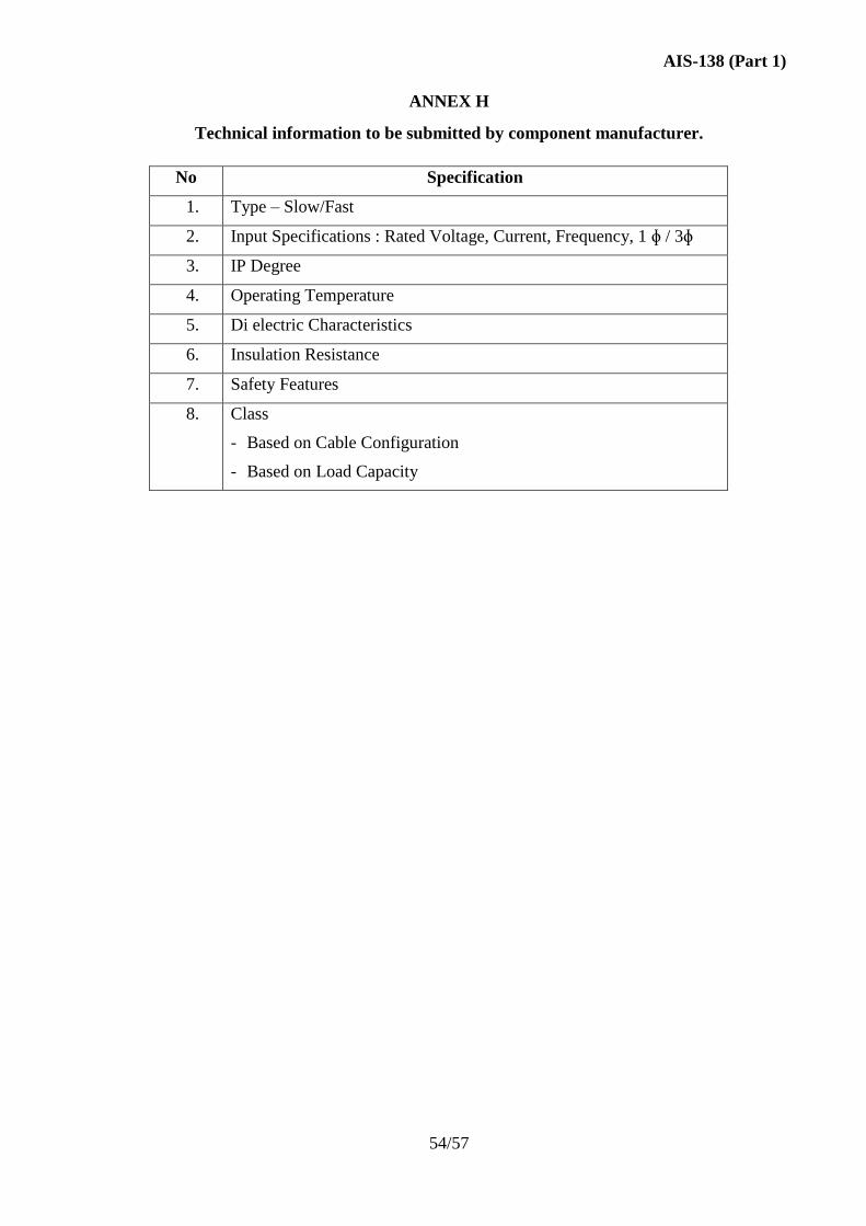
AIS-138 (Part 1)
54/57
ANNEX H
Technical information to be submitted by component manufacturer.
No Specification
1. Type – Slow/Fast
2. Input Specifications : Rated Voltage, Current, Frequency, 1 ɸ / 3ɸ
3. IP Degree
4. Operating Temperature
5. Di electric Characteristics
6. Insulation Resistance
7. Safety Features
8. Class
- Based on Cable Configuration
- Based on Load Capacity
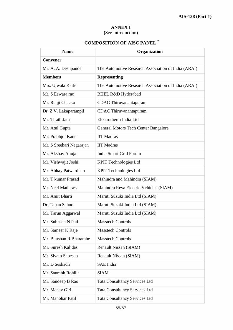
AIS-138 (Part 1)
55/57
ANNEX I
(See Introduction)
COMPOSITION OF AISC PANEL *
Name Organization
Convener
Mr. A. A. Deshpande The Automotive Research Association of India (ARAI)
Members Representing
Mrs. Ujwala Karle The Automotive Research Association of India (ARAI)
Mr. S Eswara rao BHEL R&D Hyderabad
Mr. Renji Chacko CDAC Thiruvanantapuram
Dr. Z.V. Lakaparampil CDAC Thiruvanantapuram
Mr. Tirath Jani Electrotherm India Ltd
Mr. Atul Gupta General Motors Tech Center Bangalore
Mr. Prabhjot Kaur IIT Madras
Mr. S Sreehari Nagarajan IIT Madras
Mr. Akshay Ahuja India Smart Grid Forum
Mr. Vishwajit Joshi KPIT Technologies Ltd
Mr. Abhay Patwardhan KPIT Technologies Ltd
Mr. T kumar Prasad Mahindra and Mahindra (SIAM)
Mr. Neel Mathews Mahindra Reva Electric Vehicles (SIAM)
Mr. Amit Bharti Maruti Suzuki India Ltd (SIAM)
Dr. Tapan Sahoo Maruti Suzuki India Ltd (SIAM)
Mr. Tarun Aggarwal Maruti Suzuki India Ltd (SIAM)
Mr. Subhash N Patil Masstech Controls
Mr. Sameer K Raje Masstech Controls
Mr. Bhushan R Bharambe Masstech Controls
Mr. Suresh Kalidas Renault Nissan (SIAM)
Mr. Sivam Sabesan Renault Nissan (SIAM)
Mr. D Seshadri SAE India
Mr. Saurabh Rohilla SIAM
Mr. Sandeep B Rao Tata Consultancy Services Ltd
Mr. Manav Giri Tata Consultancy Services Ltd
Mr. Manohar Patil Tata Consultancy Services Ltd
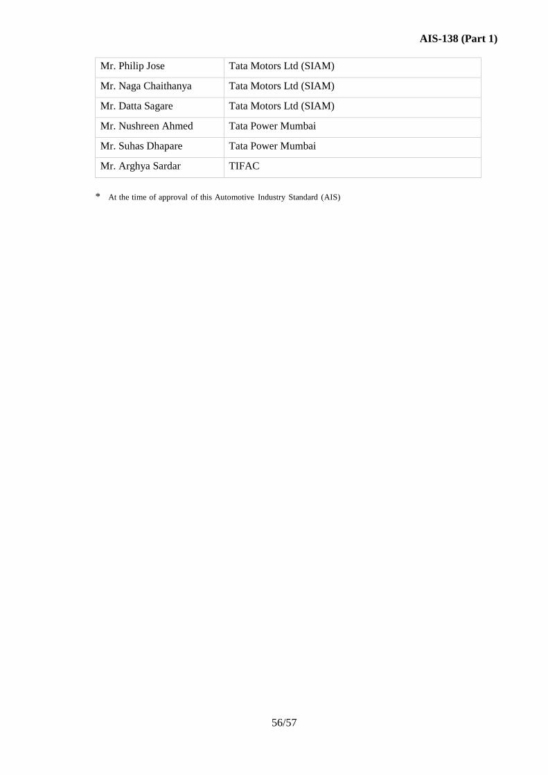
AIS-138 (Part 1)
56/57
Mr. Philip Jose Tata Motors Ltd (SIAM)
Mr. Naga Chaithanya Tata Motors Ltd (SIAM)
Mr. Datta Sagare Tata Motors Ltd (SIAM)
Mr. Nushreen Ahmed Tata Power Mumbai
Mr. Suhas Dhapare Tata Power Mumbai
Mr. Arghya Sardar TIFAC
* At the time of approval of this Automotive Industry Standard (AIS)
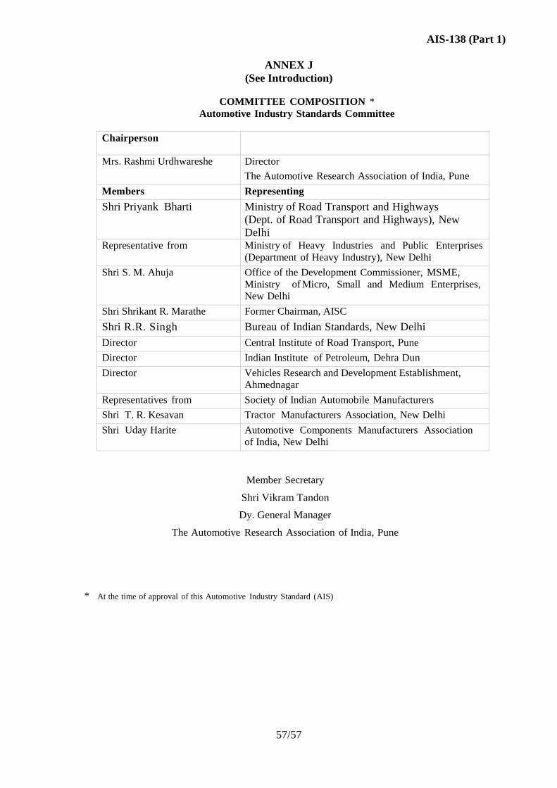
AIS-138 (Part 1)
57/57
ANNEX J
(See Introduction)
COMMITTEE COMPOSITION *
Automotive Industry Standards Committee
Chairperson
Mrs. Rashmi Urdhwareshe Director
The Automotive Research Association of India, Pune
Members Representing
Shri Priyank Bharti Ministry of Road Transport and Highways
(Dept. of Road Transport and Highways), New
Delhi Representative from Ministry of Heavy Industries and Public Enterprises
(Department of Heavy Industry), New Delhi
Shri S. M. Ahuja Office of the Development Commissioner, MSME,
Ministry of Micro, Small and Medium Enterprises,
New Delhi
Shri Shrikant R. Marathe Former Chairman, AISC
Shri R.R. Singh Bureau of Indian Standards, New Delhi
Director Central Institute of Road Transport, Pune
Director Indian Institute of Petroleum, Dehra Dun
Director Vehicles Research and Development Establishment,
Ahmednagar
Representatives from Society of Indian Automobile Manufacturers
Shri T. R. Kesavan Tractor Manufacturers Association, New Delhi
Shri Uday Harite Automotive Components Manufacturers Association
of India, New Delhi
Member Secretary
Shri Vikram Tandon
Dy. General Manager
The Automotive Research Association of India, Pune
* At the time of approval of this Automotive Industry Standard (AIS)