Embed Size (px)
Citation preview
Brochure
Global Office of Lisun Electronics Inc. http://www.Lisungroup.com Lisun Group (Hong Kong) Limited
Add: Room 803, Chevalier House, 45-51 Chatham Road South, Tsim Sha Tsui, KL, HK
Tel: 00852-68852050 Fax: 00852-30785638
Email: [email protected]
Lisun Electronics (Shanghai) Co., Ltd
Add: 113-114, No. 1 Building, Nanxiang Zhidi Industry Park, No. 1101, Huyi Road, Jiading
District, Shanghai, 201802, China
Tel: +86(21)5108 3341 Fax: +86(21)5108 3342
Email: [email protected]
Lisun Electronics Inc. (USA)
Add: 445 S. Figueroa Street, Los Angeless, CA 90071, U.S.A.
Email: [email protected]
Lisun China Factory
Add: NO. 37, Xiangyuan Road, Hangzhou City, Zhejiang Province, China
Tel: +86-189-1799-6096
Email: [email protected]
Leader in Lighting & Electrical Test Instruments Rev. 4/27/2020
Automotive Immunity Test System
(EMS-ISO7637)
Lisun Electronics Inc. [email protected] www.Lisungroup.com
-Page 1 -
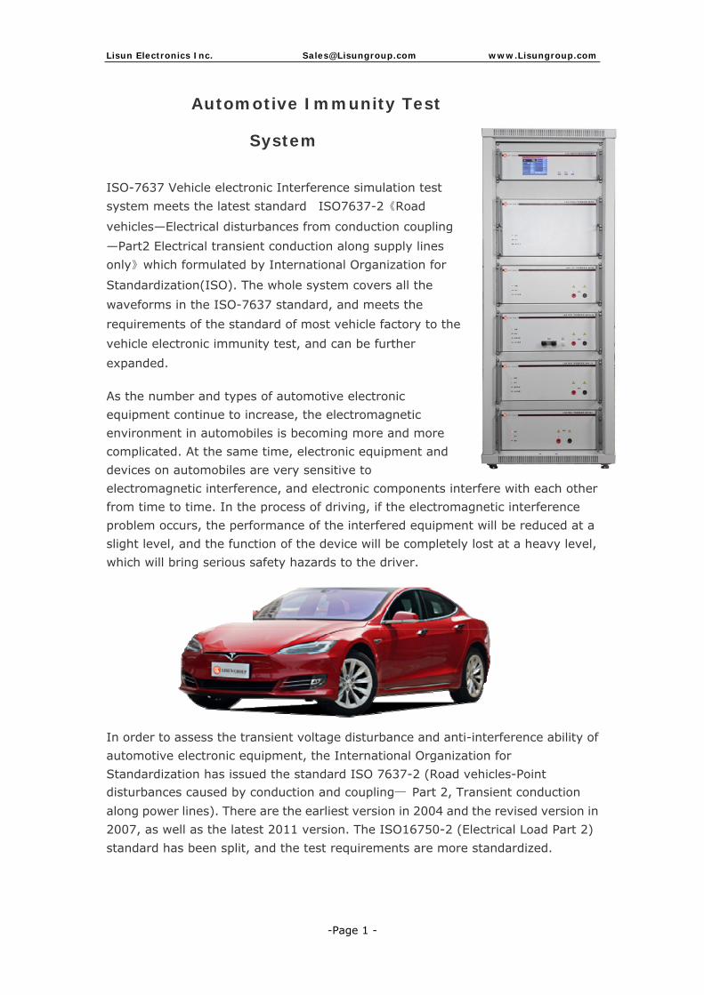
Automotive Immunity Test
System
ISO-7637 Vehicle electronic Interference simulation test system meets the latest standard ISO7637-2《Road
vehicles—Electrical disturbances from conduction coupling —Part2 Electrical transient conduction along supply lines only》which formulated by International Organization for
Standardization(ISO). The whole system covers all the waveforms in the ISO-7637 standard, and meets the requirements of the standard of most vehicle factory to the vehicle electronic immunity test, and can be further expanded.
As the number and types of automotive electronic equipment continue to increase, the electromagnetic environment in automobiles is becoming more and more complicated. At the same time, electronic equipment and devices on automobiles are very sensitive to electromagnetic interference, and electronic components interfere with each other from time to time. In the process of driving, if the electromagnetic interference problem occurs, the performance of the interfered equipment will be reduced at a slight level, and the function of the device will be completely lost at a heavy level, which will bring serious safety hazards to the driver.
In order to assess the transient voltage disturbance and anti-interference ability of automotive electronic equipment, the International Organization for Standardization has issued the standard ISO 7637-2 (Road vehicles-Point disturbances caused by conduction and coupling— Part 2, Transient conduction along power lines). There are the earliest version in 2004 and the revised version in 2007, as well as the latest 2011 version. The ISO16750-2 (Electrical Load Part 2) standard has been split, and the test requirements are more standardized.

Lisun Electronics Inc. [email protected] www.Lisungroup.com
-Page 2 -
With the continuous development and improvement of automobile manufacturing technology, and in order to better meet user’s requirement for higher quality of automobile life, automobile manufacturers increasingly use electronic and electrical systems in the process of automobile research and development, at the same time, the improvement of performance and efficiency is also increasingly dependent on the reliable work of automotive electronic systems. Therefore, the electromagnetic compatibility characteristics of automotive electronics have became one of the electronic characteristics that as important as the mechanical characteristics of automobiles. As well the test technology is an important of it.
SYSTEM CONFIGURATION
Name Model Remark Pag
e Multifunctional Immunity Test instrument Host
LIS-7600 Master control device -----3
P1/2a Simulator LIS-7610 Pulse 1 & pulse 2a -----4
P2b/4 Simulator LIS-7620 Pulse 2b & pulse 4 -----5
P3 Simulator LIS-7630 Pulse 3a & pulse 3b -----6
P2b/4 Simulator LIS-7640 Pulse 2b & pulse 4(full comply ISO7637-2 and ISO16750-2)
-----7
P5a/5b Simulator LIS-7650 Pulse 5a & pulse 5b -----8
Artificial Network LISN200 Transient conducted emission EMI test
-----9
Switch TES200N Transient conducted emission EMI test
-----9
Capacitive Coupling Clamp (Option) VFTC Vehicle electronic interference test
-----10
19 Inch Cabinet (Option) CASE-19 Loading control host device and all pulse generator together
EMS-ISO7637 Automotive Immunity Test System Software -----11
Note the following: If you need programmable waveform generator and DC source to simulate a battery as well need to do transient conducted emission EMI test, you should choose the items which marked by Blue. If choose LIS-7640, then there is no need choose LIS-7620 again. Technical Introduction: 1. The system covers all the waveforms in the ISO-7637-2:2011 standard, it can provide all eight kinds of waveforms. And LISUN developed arbitrary waveform generator can customize various waveforms to meet the requirements of most OEMs for power supply changes.
Lisun Electronics Inc. [email protected] www.Lisungroup.com
-Page 3 -
2. Man-machine interface: big size LCD, color touch screen, master-slave module extension technology architecture, fully intelligent network control, easy to upgrade. 3. Full allocation of various types of host computer interface, it can be connected with the host computer to carry out waveform programming to achieve human-computer information exchange and control. 4. It can do vehicle test for 12V/24V system. 5. Arbitrary waveform generator included high-power linear amplifier frequency response can be up to 150KHz and supports power expansion function; it rise or fall edge response time less than 3.5us, it can meet test demand of different auto manufacturers. 6. Customizable waveforms: 16 types of waveform elements such as DC, positive black wave, triangular wave, square wave and exponential wave, etc. 7. The arbitrary waveform generator application bipolar programmable power supply, it not only can meet the test demand of positive and negative voltages, but also can meet test demand of zero crossings (from positive to negative or from negative to positive). 8. Professional AUTOPRO test software, open management, customizable waveforms, edited waveforms can be stored, automatically generate test report and format can be edite. Also it can be recalled directly at next test. 9. Built-in many domestics and foreign auto manufacturers standards. User can set standards directly at software to match test
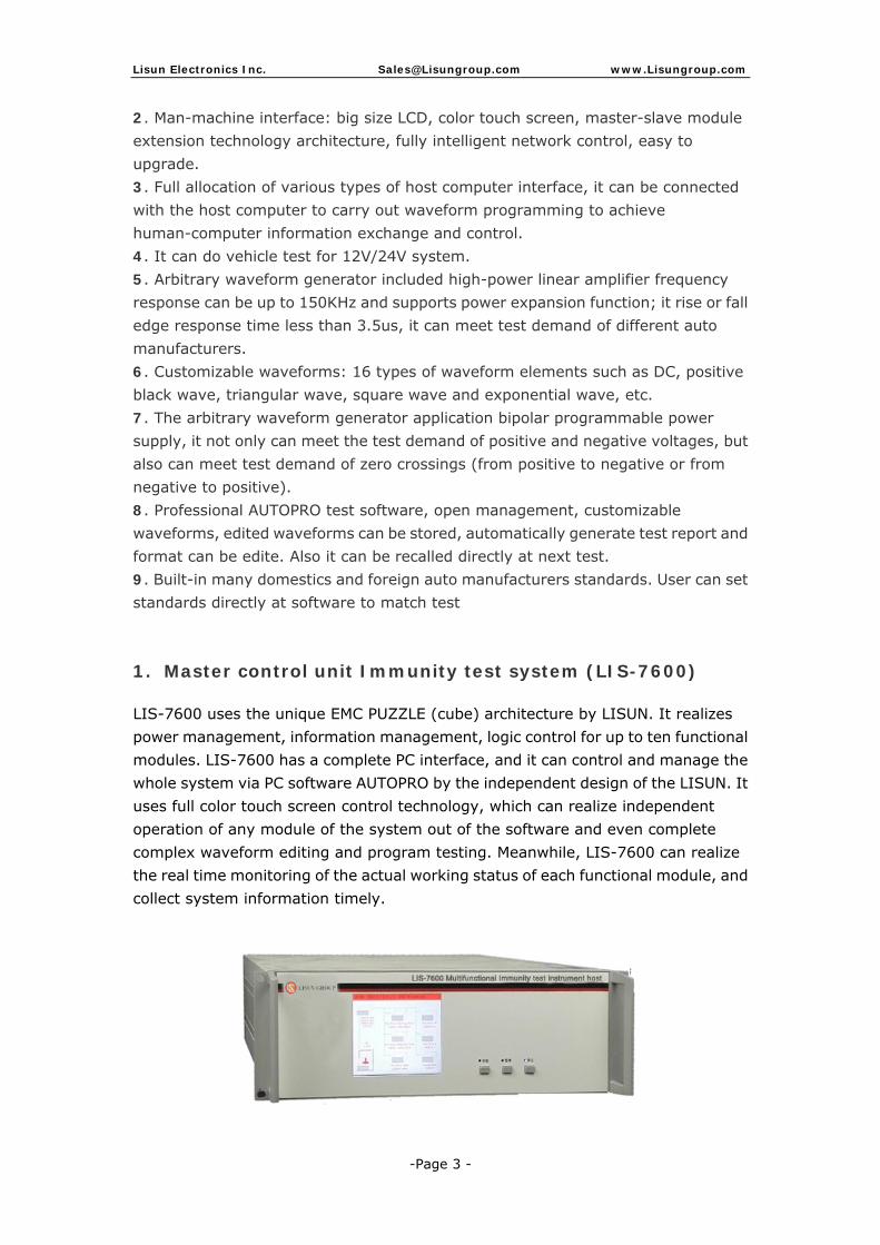
1. Master control unit Immunity test system (LIS-7600)
LIS-7600 uses the unique EMC PUZZLE (cube) architecture by LISUN. It realizes power management, information management, logic control for up to ten functional modules. LIS-7600 has a complete PC interface, and it can control and manage the whole system via PC software AUTOPRO by the independent design of the LISUN. It uses full color touch screen control technology, which can realize independent operation of any module of the system out of the software and even complete complex waveform editing and program testing. Meanwhile, LIS-7600 can realize the real time monitoring of the actual working status of each functional module, and collect system information timely.

Lisun Electronics Inc. [email protected] www.Lisungroup.com
-Page 4 -
2. Pulse 1/2a generator (LIS-7610)
Pulse 1: Simulating the transient disturbance caused by inductive load switching off when vehicle is in parallel with the tested product.
Pulse 2a: Simulating the transient disturbances in the on-line beam induced by the device are suddenly cut off when the device is in parallel with the measured object.
Figure 1: Pulse 1 Figure 2: Pulse 2a
Technical Specification:
Item Specifications (Pulse 1) Specifications (Pulse 2a)
Output voltage (Us): 0~ -700V 1~150V
Output resistance (Ri): 2Ω,4Ω,10Ω,30Ω,50Ω 2Ω,4Ω,10Ω,30Ω,50Ω
Pulse width (Td): 50us,200us,300us,500us,1ms,2ms
50us,200us,300us,500us,1ms,2ms
Rise time (Tr): 1us: 0.5~1μs, 3us: 1.5~3μs
1us: 0.5~1μs
Repetition period (T1): 0.2~99.99
DUT power capacity Build-in CDN: DC60V/30A

Lisun Electronics Inc. [email protected] www.Lisungroup.com
-Page 5 -
3. Pulse 2b/4 generator (LIS-7620)
Pulse 2b: Simulating the transient interference caused by the generator effect of the DC motor is cut off. Pulse 4: Simulating the power supply voltage variation caused by starting the internal combustion engine starter-motor circuit
Figure 1: Pulse 2b Figure 2: Pulse 4
Technical Specification:
Item Parameters Specifications
Pulse 2b Ua, Us 13.5V, 27V
Output resistance (Ri) 0Ω~0.05Ω
Pulse width (Td) 30~5000ms
T12,Tr,T6 0.5~10ms
Pulse 4 Ub 13.5V, 27V
Us, Ua 0~ -UB
Output resistance (Ri) 0Ω~0.02Ω
Drop 1 duration time (T7):
1~1000ms
Fall 1 rise time (T8): 2~100ms
Drop 2 duration time (T9):
0.1~30s
Fall time (T10): 5~10ms
Fall 2 rise time (T11): 1~1000ms
DUT power capacity
12V, 24V test system: 30A

Lisun Electronics Inc. [email protected] www.Lisungroup.com
-Page 6 -
4. Pulse 3a/3b generator (LIS-7630)
Pulse 3a: Simulating the transient interference caused by switching of analog inductive load. (Positive) Pulse 3b: Simulating the transient interference caused by switching of analog inductive load. (Negative)
Figure 1: Pulse 3a Figure 2: Pulse 3b
Technical Specification:
Item Specifications
Output voltage (Us) 0V~ ±800V
Output resistance (Ri) 50Ω Pulse width(Td) 150ns±45ns Pulse group width(T4) 10~100ms
Pulse group interval (T5) 0.01~60s
Rise time (Tr) 5ns±1.5ns
Repetition period (T1) 10~2000us
DUT power capacity Build-in CDN, DC60V/30A

Lisun Electronics Inc. [email protected] www.Lisungroup.com
-Page 7 -
5. Pulse 2b/4 generator (LIS-7640)
Technical Specification:
• Rated output: 400W (40V/10A) can be expand to
2000W (40V/50A)
• LIS-7640(Option): It included P2b and P4 waveform
generator to fully meet ISO7637-2 and ISO16750-2
Figure 1: Pulse 2b Figure 2: Pulse 4
Item Parameters Specifications
Pulse 2b Pulse peak voltage (Us):
0V~40V(±10%)
Input impedance (Ri): 0~0.05Ω
Pulse width (Td): 0.1~5s(±10%)
Rise time (Tr): 0.5~10ms(±20%)
Fall time (T12): 0.5~10ms(±20%)
Wait time (T6): 0.5~10ms(±20%)
Pulse 4 Drop voltage 1 (Us): 0V~16V (±10%) (12V system); 0V~32V (±10%) (24V system)
Drop voltage 2 (Ua): 0V~16V (±10%) (12V system); 0V~32V (±10%) (24V system)
Input impedance (Ri): 0~0.02Ω
Fall time (T10): 5~10ms (±10%)
Drop 1 duration time (T7):
1~1000ms (±10%)
Fall 1 rise time (T8): 2~100ms (±10%)
Drop 2 duration time (T9):
0.1~30s (±10%)
Fall 2 rise time (T11): 1~1000ms (±10%)

Lisun Electronics Inc. [email protected] www.Lisungroup.com
-Page 8 -
6. Pulse 5a/5b generator (LIS-7650)
P5a: Simulating the transient interference when the alternator is generating charging current while the battery is disconnected, and there are still other loads on the generator circuit P5b: Simulating the transient interference that occurs due to the suppression circuit in the generator circuit under the above conditions
Figure 1: Pulse 5a Figure 2: Pulse 5b
Technical Specification: • Pulse peak voltage (Us): 20V~200V(±10%); • Input impedance (Ri): 0.5Ω to 8Ω; • Pulse width (td): 40ms, 100ms, 200ms, 300ms, 350ms, 400ms (±20%); • Rise time (tr): 5ms~10ms; • Pulse action time: 60s~9999s(±10%);
Item Parameters Specifications
Pulse 5a Pulse peak voltage (Us):
12V system: 20V~100V(±10%) 24V system: 20V~200V(±10%)
Input resistance (Ri): 12V system: 0.5Ω~4Ω 24V system: 1Ω~8Ω
Pulse width (Td): 40ms, 100 ms, 200ms, 300ms, 350ms, 400ms (±20%)
Rise time (Tr): 5 ms~10 ms
Pulse action time: 60s~9999s
Pulse 5b Pulse peak voltage (Us):
12V system: 20V~100V(±10%) 24V system: 20V~200V(±10%)
Output resistance (Ri): 12V system: 0.5Ω~4Ω 24V system: 1Ω~8Ω
Pulse action time: 60s~9999s
DUT power capacity
12V, 24V test system: 30A

Lisun Electronics Inc. [email protected] www.Lisungroup.com
-Page 9 -
7. Transient Conduction Emission (EMI) Test (LISN200、TES200N)
Emission test measures the interference caused by the work of the test device (DUT). The vehicle mounted electronic transient conduction and emission measurement mainly refers to the interference caused by the test device in the start and stop of the test device. TES200N automobile electronic conduction transient emission test system completely meets the ISO7637-2 standard on the transient emission measurement requirements. It contains complete control unit, artificial power network, mechanical switch simulation system, the electronic switch simulation system. It uses unique touch screen control method designed by LISUN and good test characteristics and professional & convenient test system for automobile electronics. TES200N is the certified products by transient emission measurement for automotive electronics. Technical Parameter: System Electronic switch Battery Current 100A Switching Time 300ns±20% Battery Voltage 0-60VDC Voltage Drop <1V@25A Bypass Resistance
10,20,40,120Ω, EXT Transient Voltage Protection
>440V
Trigger mode External, Internal, Manual
Battery off time 10ms~10s
Battery power supply time
10ms~10s
Relay Available Voltage
12V,24V,36V (42V Application of power supply system)
Mechanical Switch Artificial Power Network
Switching capacity
100A & 25A Inductance / Capacitance / Resistance
5uH/0.1uF/50Ω

Lisun Electronics Inc. [email protected] www.Lisungroup.com
-Page 10 -
8. Capacitive Coupling Clamp for Vehicle Electronic
Interference Test (VFTC)
The VFTC capacitive coupling clamp is special design for signal line immunity test requirement(which also can be used for power line test) of the P3 pulse test (which is a fast transient pulse) in the ISO7637-3 and GB / T32960.2-2016 standards. The performance of the design equipment comply the ISO7637-3 standard requirement.
Technical Specification:
Model Number VFTC
Coupling Capacitance 100~200pF
Injection Terminal BNC
Dimention 1250*300*82mm(Width*Depth*Hei
ght)
Weight 15kg
The next pages are test software