Embed Size (px)
Citation preview

WHITE PAPER
Automotive High-Speed Data
2021
Table of contents
1. The context of connected mobility . . . . . . . . . . . . . . . . . . . . . . . . . . . . . . . . . . . . . . . . . . . . . . . . . . . . . . 1
1.A. Current State-of-the-Art: What does a High-Speed Data Rate mean in automotive terms? . . . . . . . . . . . . . . . . . . . . . . . . . . . . . . . . . . . . . . . . . . . . . . . . . . . . . . . . . . . . . . . . . . . . . . . . . 1
1.B. In-car services . . . . . . . . . . . . . . . . . . . . . . . . . . . . . . . . . . . . . . . . . . . . . . . . . . . . . . . . . . . . . . . . . . . . . . . . . . . . . . . . . . . . . . . . . . . . . . . 2
2. ACOME Telecoms – Automotive expertise . . . . . . . . . . . . . . . . . . . . . . . . . . . . . . . . . . . . . 4
3. Open Alliance, other standards and recommendations . . . . . . . . . . . . 5
3.A. Unified communications . . . . . . . . . . . . . . . . . . . . . . . . . . . . . . . . . . . . . . . . . . . . . . . . . . . . . . . . . . . . . . . . . . . . . . . . . . . . . . 5
3.B. Cables designed specifically for high-speed data transmission in automotive applications . . . . . . . . . . . . . . . . . . . . . . . . . . . . . . . . . . . . . . . . . . . . . . . . . . . . . . . . . . . . . . . . . . . . . . . . . . 5
4. From electrical cable to communication bus (differences and challenges) . . . . . . . . . . . . . . . . . . . . . . . . . . . . . . . . . . . . . . . . . . . . . . . . . . . . . . . . . . . . . . . . . 8
4.A. The conductor . . . . . . . . . . . . . . . . . . . . . . . . . . . . . . . . . . . . . . . . . . . . . . . . . . . . . . . . . . . . . . . . . . . . . . . . . . . . . . . . . . . . . . . . . . . . . . . . 8
4.B. The Geometry… Where the automotive and telecom meet . . . . . . . . . . . . . . . . . . . 9
4.C. The insulation . . . . . . . . . . . . . . . . . . . . . . . . . . . . . . . . . . . . . . . . . . . . . . . . . . . . . . . . . . . . . . . . . . . . . . . . . . . . . . . . . . . . . . . . . . . . . . . . 9
4.D. The conductor pair environment . . . . . . . . . . . . . . . . . . . . . . . . . . . . . . . . . . . . . . . . . . . . . . . . . . . . . . . . . . . . . . . . 11
4.E. Twisted pair assembly . . . . . . . . . . . . . . . . . . . . . . . . . . . . . . . . . . . . . . . . . . . . . . . . . . . . . . . . . . . . . . . . . . . . . . . . . . . . . . . . . 12
4.F. Shielding . . . . . . . . . . . . . . . . . . . . . . . . . . . . . . . . . . . . . . . . . . . . . . . . . . . . . . . . . . . . . . . . . . . . . . . . . . . . . . . . . . . . . . . . . . . . . . . . . . . . . . . . 13
4.G. Shielding assembly . . . . . . . . . . . . . . . . . . . . . . . . . . . . . . . . . . . . . . . . . . . . . . . . . . . . . . . . . . . . . . . . . . . . . . . . . . . . . . . . . . . . . . 14
5. ACOME metrology recommendations . . . . . . . . . . . . . . . . . . . . . . . . . . . . . . . . . . . . . . . . . . . . . . . . 16
5.A. Different measures for different applications. . . . . . . . . . . . . . . . . . . . . . . . . . . . . . . . . . . . . . . . . . 16
5.B. Expert control of measurement processes . . . . . . . . . . . . . . . . . . . . . . . . . . . . . . . . . . . . . . . . . . . . . . 18
6. Product recommendations by ACOME . . . . . . . . . . . . . . . . . . . . . . . . . . . . . . . . . . . . . . . . . . . . . . . 19
www.acome.com 1
1. The context of connected mobility
1.A. Current state-of-the-art: what does a High-Speed Data Rate mean in automotive terms?
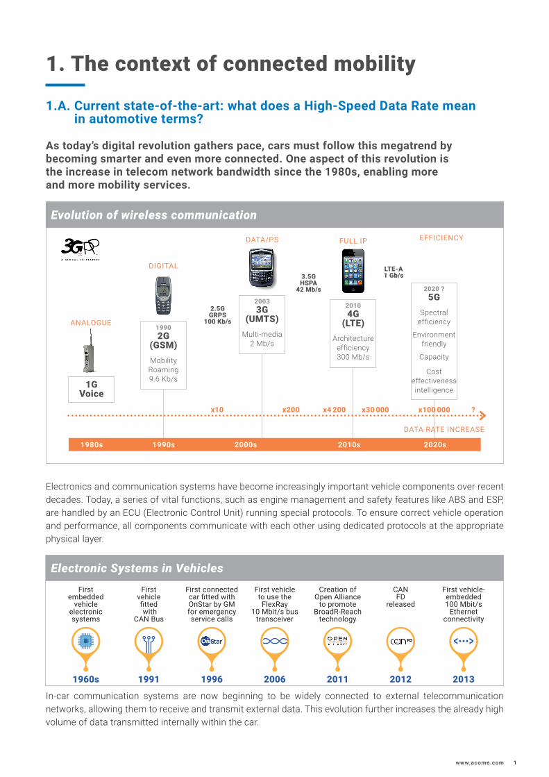
As today’s digital revolution gathers pace, cars must follow this megatrend by becoming smarter and even more connected. One aspect of this revolution is the increase in telecom network bandwidth since the 1980s, enabling more and more mobility services.
Electronics and communication systems have become increasingly important vehicle components over recent decades. Today, a series of vital functions, such as engine management and safety features like ABS and ESP, are handled by an ECU (Electronic Control Unit) running special protocols. To ensure correct vehicle operation and performance, all components communicate with each other using dedicated protocols at the appropriate physical layer.
In-car communication systems are now beginning to be widely connected to external telecommunication networks, allowing them to receive and transmit external data. This evolution further increases the already high volume of data transmitted internally within the car.
DATA RATE INCREASE
1980s 1990s
x10 x200 x4 200 x30 000 x100 000 ?
2000s 2020s2010s
1GVoice
19902G
(GSM)MobilityRoaming9.6 Kb/s
20033G
(UMTS)Multi-media
2 Mb/s
2.5GGRPS
100 Kb/s
2020 ?5G
Spectralefficiency
Environmentfriendly
Capacity
Cost effectivenessintelligence
3.5GHSPA
42 Mb/s
LTE-A1 Gb/s
EFFICIENCY
ANALOGUE
DIGITAL
DATA/PS FULL IP
Electronic Systems in Vehicles
1991
First vehicle fitted with
CAN Bus
1996
First connected car fitted with OnStar by GM for emergency service calls
2006
First vehicle to use the FlexRay
10 Mbit/s bus transceiver
2011
Creation of Open Alliance
to promote BroadR-Reach
technology
2012
CAN FD
released
2013
First vehicle-embedded 100 Mbit/s
Ethernet connectivity
1960s
First embedded
vehicle electronic systems
Evolution of wireless communication
20104G
(LTE)Architecture
efficiency300 Mb/s
2
1.B. In-car services
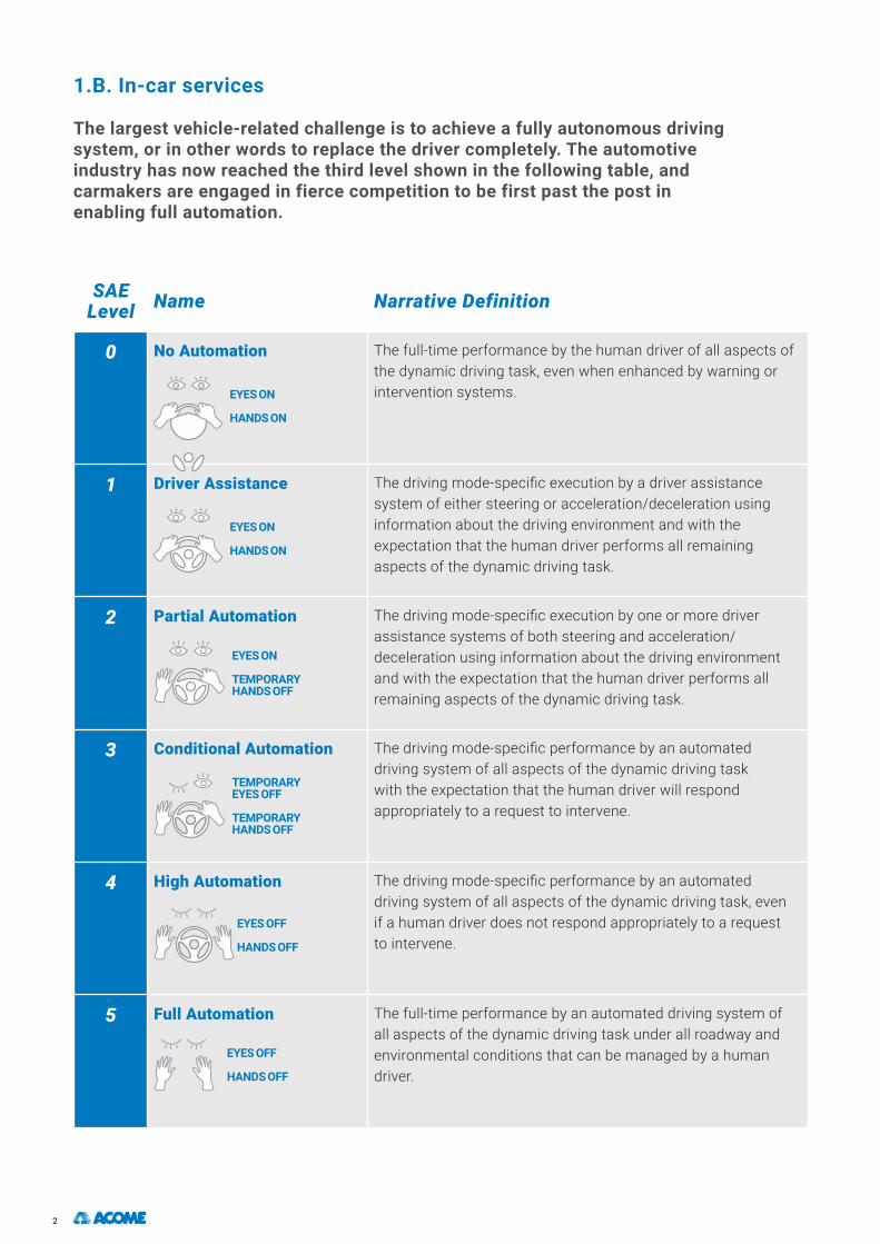
The largest vehicle-related challenge is to achieve a fully autonomous driving system, or in other words to replace the driver completely. The automotiveindustry has now reached the third level shown in the following table, and carmakers are engaged in fierce competition to be first past the post in enabling full automation.
SAE Level Name Narrative Definition
0 No Automation
EYES ON
HANDS ON
The full-time performance by the human driver of all aspects of the dynamic driving task, even when enhanced by warning or intervention systems.
1 Driver Assistance
EYES ON
HANDS ON
The driving mode-specific execution by a driver assistance system of either steering or acceleration/deceleration using information about the driving environment and with the expectation that the human driver performs all remaining aspects of the dynamic driving task.
2 Partial Automation
EYES ON
TEMPORARY HANDS OFF
The driving mode-specific execution by one or more driver assistance systems of both steering and acceleration/deceleration using information about the driving environment and with the expectation that the human driver performs all remaining aspects of the dynamic driving task.
3 Conditional Automation
TEMPORARY EYES OFF
TEMPORARY HANDS OFF
The driving mode-specific performance by an automated driving system of all aspects of the dynamic driving task with the expectation that the human driver will respond appropriately to a request to intervene.
4 High Automation
EYES OFF
HANDS OFF
The driving mode-specific performance by an automated driving system of all aspects of the dynamic driving task, even if a human driver does not respond appropriately to a request to intervene.
5 Full Automation
EYES OFF
HANDS OFF
The full-time performance by an automated driving system of all aspects of the dynamic driving task under all roadway and environmental conditions that can be managed by a human driver.

www.acome.com 3
Now freed from driving duties, human attention can be focused on other tasks, which in turn will drive the emergence of new in-car services.There are two obvious areas: leisure and work.Leisure services:
• Music and movies (e.g. 4K movies require bandwidth of 20 Mb/s)• Gaming, etc..
Professional services:• In-vehicle conference calls• Cloud server access, etc.
On the other hand, increased automation will demand a more complex level of communication between autonomous vehicles and their external environment to ensure road safety. For example, a vehicle should be able to communicate its position, its speed and intended trajectory to other road users to prevent collisions. This will be done thanks to Vehicule to Vehicule communication (V2V communication). This technology allows vehicules to broadcast and receive omnidirectional messages by wireless communication).A vehicle should comply with traffic regulation systems to ease traffic flow. Vehicule to Infrastructure(V2I) will ensure this wireless and bidirectional communication between vehicules and road equipements. .Autonomous driving will generate a huge amount of data to be managed, transmitted and processed. Sensors will translate environmental information into digital data requiring equally huge bandwidth consumption (20 Mb/s single-channel LiDAR ( Ligth Detection And Ranging ).The embedded network must therefore be highly responsive in order to avoid road hazards safely. For example, a car traveling at 130 kmph (80 mph) is covering more than 35 meters (115 feet) per second.Lastly, connected cars must offer extreme levels of safety and reliability. With human lives at stake, otherwise minor network failures can have terrible consequences.Providing such assurance requires a hierarchy of network security levels. The separation between levels may be physical or software-defined..
Source: http://automotive.electronicspecifier.com/air-conditioning/real-time-automotive-ethernet
Example of Future Automotive Ethernet Backbone Network
Advanced Driver Assistance
Body
CAN (-FD)
LIN FlexRayChassis
Powertrain CAN (-FD)
CAM CAM
DomainGateway
ECU
ECU
ECU
ECU
ECU
ECU
ECU
ECU
ECU
ECU
ECU
ECUECU ECU
DomainGateway
DomainGateway
Infotainment
Switched Ethernet Network

4
2. ACOME Telecoms – Automotive expertise
ACOME has all the resources needed to respond effectively to the future challenges facing the automotive industry.
ACOME currently delivers more than 300,000 km of pairs and 5 million kilometers of optical fiber to its telecoms customers every year, while the ACOME Automotive branch manufactures around 4 million kilometers of cables and wires annually.ACOME has been closely involved with the developing telecoms industry ever since the company was founded 85 years ago. ACOME is expert in the advanced technologies required to design and produce the safe, secure and reliable cables used to carry sensitive data. Today, ACOME has the capability to offer LAN products that comply fully with the latest standards, and coaxial cables designed specifically for cell phone network antennas.
ISO 11801 product categories Frequency range Bit rate (distance)
Cat 5e up to 100MHz 1Gbit/s (100 m)
Cat 6 up to 250 MHz 10Gbit/s (56 m)
Cat 6A up to 500 MHz 10Gbit/s (100 m)
Cat 7 up to 600 MHz 10Gbit/s (100 m)
Cat 7A up to 1 000 MHz 10Gbit/s (100 m)
Cat 8 up to 2 000 MHz 40Gbit/s (30 m)
In addition to this expertise, ACOME has more than 65 years’ experience in supplying cables to automotive wiring harness manufacturers.ACOME has in-depth knowledge and capability in the two key areas to provide dedicated solutions for autonomous and connected vehicles:
The first is high-speed data transfer cable technology, and the second is our automotive industry experience, which gives us a comprehensive understanding of the harsh constraints imposed by the automotive cabling environment: vibration, extremes of temperature, abrasion, chemical attack, etc.

www.acome.com 5
3. Open Alliance, other stan dards & recommendations
3.A. Unified communications
Of all the protocols available, single-pair Ethernet (standardized by the OPEN (One Pair EtherNet) Alliance) stands out as particularly promising. Although Ethernet technology is not in widespread automotive use, the availability ofsingle-pair cables (which are cheaper and save weight) in lengths suitable for the car or truck manufacturing industries (15-40 meters) will allow this protocol to become more pervasive in the automotive industry.
Ethernet offers a number of advantages when compared with other data transmission technologies. These include its massively widespread use in the telecommunications industry, which will enable the sharing of electronic component design, which will in turn reduce costs. Ethernet and IP also bring with them the possibility of unifying communication originating from different sources. Looking to the future, this could potentially lead to vehicles having a single unified data transmission architecture. Some features, including security features, will require low latency and/or dedicated bandwidth, and may demand a level of quality of service that Ethernet does not deliver natively. The generous sizing of the data transmission architecture made possible by the use of low-cost components and overlays (such as TSN) will ensure secure operation of all hardware, and provide the real-time capability and dependability essential for those functions.Initiated by BroadR-Reach and first specified by the OPEN Alliance, single-pair Ethernet is now being standardized by the IEEE802.3 working group responsible for all Ethernet standards. Initially focused on a bit rate of 100 Mbps, this technology will be extended to include other speeds (10 Mbps, 1 Gbps and even several Gbps).
3.B. Cables designed specifically for high-speed data transmission in automotive applications
This increase in supported bit rates goes hand-in-hand with the need for high-quality transmission media. To transmit these rates, cable design and manufacture must be carefully controlled to limit the impact of the cable on the transmitted signals. When traveling through a cable, the signal is modified: part of it is absorbed by the cable (attenuation) and another part is returned to the transmitter (return losses). Signal symmetry is also essential for avoiding electromagnetic noise, since transmission is in differential (or symmetrical) mode. To successfully resolve these parameters, it is crucial that cable and wire dimensions and materials are meticulously controlled for all cable components: conductor, insulation, sheathing and shielding.
Close dimensional control of all cable components is vital. To illustrate the order of magnitude involved, a wire diameter variance of 100μm for a pair of 0.35mm² wires changes the characteristic impedance by nearly 10%, and symmetry tolerances are even more demanding.
Equally tight control of insulation and, more specifically, its dielectric characteristics is also essential. All these characteristics must – of course – be ensured not only on completion of manufacture, but also in standard and hostile environments (temperature, aging, etc.).
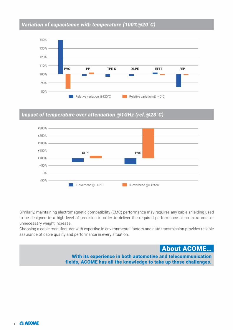
In this respect, not all materials and cable constructions are equal. PVC in particular does not deliver good signal transmission performance, since its performance varies greatly with temperature, making it very difficult to maintain specifications at low and high temperature extremes.
6
Similarly, maintaining electromagnetic compatibility (EMC) performance may requires any cable shielding used to be designed to a high level of precision in order to deliver the required performance at no extra cost or unnecessary weight increase.Choosing a cable manufacturer with expertise in environmental factors and data transmission provides reliable assurance of cable quality and performance in every situation.
About ACOME…With its experience in both automotive and telecommunication
fields, ACOME has all the knowledge to take up those challenges.
Variation of capacitance with temperature (100%@20°C)
Impact of temperature over attenuation @1GHz (ref.@23°C)
140%
130%
120%
110%
100%
90%
80%
+300%
+250%
+200%
+150%
+100%
+50%
0%
-50%
Relative variation @120°C
PPPVC
XLPE
TPE-S XLPE EFTE FEP
IL overhead @ - 40°C
Relative variation @ - 40°C
IL overhead @+125°C
PVC

www.acome.com 7
Signal is the term used to describe the physical form of the data to be transmitted from one end of the cable to the other. It is an electromagnetic wave that carries energy from a transmitter to a receiver. The transmitter creates the signal and the receiver must interpret it to reconstruct the information it contains. The channel linking the two must minimize any deterioration of the signal.
Noise describes the set of events containing energy in the same form as the signal, regardless of its source (not necessarily the transmitter), and containing no information. At the receiver, this energy is added to the signal and contaminates it. The level of noise must be reasonable compared with the level of signal received if the receiver is to interpret the message correctly.
Communication Channel is the set of components forming the transmission link (cables, connectors, etc.) between two electronic cards. Its electrical performance must meet specific criteria to enable effective signal transmission. These performance criteria include:
IL (insertion loss): in order to be correctly interpreted by the receiver and not be obliterated by noise, the signal must have sufficient energy when it arrives at the receiving end of the channel. Unfortunately, part of its energy is lost during its transmission through the channel. The energy lost between the channel input and the output is the IL. These losses may have multiple origins.
Impedance (Zc) can be interpreted as the environment seen by the signal as it propagates through the channel; it depends on variables, such as channel dimensions, signal speed, etc. This environment must be as regular as possible to avoid reflections when passing from transmitter to connector to cable, and vice versa. We begin by defining a nominal impedance (e.g. 100 Ohms) to which all components must comply as closely as possible.
RL (Return Loss): when impedance changes, part of the energy of the signal is reflected back through the transmission channel. This reflected signal is referred to as RL. This signal energy flows in the reverse direction, and may therefore interfere with the transmitter and/or receiver by creating noise.
Crosstalk: when multiple channels are close together, a proportion of their energy can pass from one channel to another, creating crosstalk. Because this part of the signal is no longer within its dedicated channel, it becomes undesirable energy, and therefore noise. If this noise arrives at the transmitter end of the channel, it is referred to as NEXT (Near End Crosstalk). If it arrives at the receiver end, it is referred to as FEXT (Far End Crosstalk). This crosstalk is described as endogenous when it originates in the same (multichannel) cable or exogenous when it originates in a separate cable, in which case it is referred to as Alien crosstalk. When compared with the attenuation value, this crosstalk level gives a signal-to-noise ratio, which provides a good indicator of overall channel quality. In this specific instance, the resulting ratio is referred to as the Attenuation-to-Crosstalk ratio (ACR), which may be either ACR-N (Near end) or ACR-F (Far end).
Unbalance attenuation: when using a twisted pair, symmetry is crucial. The two wires carry exactly opposite signals (differential transmission mode), and the pair must be perfectly symmetrical to keep those signals opposite throughout the channel to the receiver. If not, part of the signal energy becomes common mode noise radiated to create noise in other channels while being lost for the purposes of transmission. Similarly, such asymmetry allows interference to accumulate in the differential mode and reach the receiver as noise that disrupts the signal. These asymmetries can either induce a return of the signal to the transmitter (Longitudinal Conversion Loss or LCL) or transform the signal through its propagation to the receiver (Longitudinal Conversion Transfer Loss or LCTL).
Glossary — Signal transmission terminology

8
4. From electrical cable to communication bus (differences and challenges)
Communication networks were first introduced into automotive applications to link Electronic Controller Units (ECUs). Since then, the need to meet the requirements of individual in-car systems has resulted in the development of multiple protocols (LIN, CAN, LVDS, CAN FD, FlexRay, MOST, etc.).
Today’s focus is on the Ethernet protocol and the use of a single pair because of the high bandwidth capacity this protocol can deliver and its benefits in terms of lower cost and technological maturity. The details given in this section are based on the single pair communication bus, and examine how it differs from standard electrical cable and the challenges involved.
4.A. The conductor
There is a significant difference between automotive and telecoms conductor design. The telecoms industry uses mainly solid (copper) conductors, whereas automotive applications use multi-strand conductors.From the telecoms perspective, the more circular and regular the conductor is, the more precise the wire construction and the higher the quality of transmission is (Fig.1).From the automotive perspective, the more strands there are in the conductor construction, the higher the level of mechanical performance delivered by the resulting product is (Fig.2).
The multi-strand design used for vehicle data transmission is more complex than the circular telecoms design due to the irregularity of the outer shape. The distance between the two conductors varies along the length of the cable (Fig.3), which can affect the performance of the cable and transmission (construction stability relies mainly on Impedance – Zc).
For a more detailed explanation of assembled conductor behavior, it is first necessary to understand skin effects and proximity effects.Any conductive material may be used for the conductor.
Fig.1
Solide conductor
Fig.2
Stranded conductor
Fig.3
Conductor distance

www.acome.com 9
Today, the telecoms industry uses mainly copper, as does the automotive industry. Nevertheless, alternatives do exist. Stranded copper (or copper-based materials, such as copper alloys, tinned copper, etc.) are preferred by the automotive industry for their flexibility, mechanical behavior and electrical lifespan (Fig.4).In some applications, humidity/water or temperature may have an effect on bare copper solutions, in which case tinned copper may provide a solution. Tinned copper has a much longer lifespan than bare copper and offers excellent corrosion resistance, especially in wet conditions (corrosion, progressive fatigue and breakage).
About ACOME…ACOME draws and strands conductors in-house, and has full
control of its conductor quality process.
4.C. The Geometry… Where the automotive and telecom meet
In telecommunications, high-precision design of twisted-pair cables is essential to maintain consistent spacing of the two conductors to ensure capacity stability and, therefore, characteristic impedance.The automotive industry consortium for the Ethernet protocol communication bus has determined 100 Ohms as the standard for cable characteristic impedance, and for other cable-related components. Expertise in variable geometry is required to ensure compliance with the appropriate parameters. In the automotive industry, concentricity of above 80% is required, whereas telecoms applications demand better than 95% concentricity. However, the automotive industry is now converging with the telecoms value to achieve the best transmission parameters.
Conductor concentricity where D1≠D2 as a result of centering stability lessons learnt in both industries
As previously mentioned, characteristic impedance ( ) is related to capacity ( )and therefore to variables such as dielectric ( ), conductor ( ), design and dimensional specifications. Hence the importance of conductors being as circular as possible in cross-section ( ) to avoid any spacing disparities. This is expressed by the following formula:
To understand what is happening in greater detail, we must focus on skin and proximity effects. In a solid insulated conductor, the skin effect is the tendency of the current to travel outer of the center the conductor as the frequency increase. For high frequencies, the current is thus distributed on a lower cross section which increase the resistivity (Fig.6)
Fig.4
Conductortype
Tinned... ... or bare ?
AutoConcentricity>80%
TelecomsConcentricity>95%D1 D2
In HF: With: εo=8,84x10¹²F/m d
D
Fig.5
Characteristic impedance formula

10
When two insulated conductors are close one to another, current distribution changes and is concentrated at the surface of the adjacent conductors: this is the proximity effect. In the same way as the skin effect, the higher the frequency, the more the surface concentration changes (Fig.7).
Multi-strand conductors are at a disadvantage in this respect, because the current will be concentrated less uniformly than in a solid conductor, and the gaps between strands will amplify the skin effect as a result of magnetic fields on the surface of each strand of wire.
About ACOME…ACOME is a recognized telecoms industry expert and supplier
with more than 85 years’ experience of developing data transmission solutions based on minutely
accurate control of cable geometry and the use of high-precision processes.
4.C. The insulation
For a good signal transmission through the cable, the main consideration for insulation is its dielectric properties. This is one of the most important issues for both telecoms and automotive applications. Dielectric properties and their stability in harsh environmental conditions are determining factors for long- term cable performance.
About the materialThe fillers used in thermoplastics affect their dielectric performance, and must be carefully specified in order to achieve the required levels of fire/heat resistance performance. The addition of fillers to a natural polymer will affect the dielectric permittivity of the material, and where used for a pair, this factor will influence its characteristic impedance and capacity.
Fig.6
Skin effectFrequencyincrease (Hz)
Skin deph is reduced as the frequency increase
Distribution of the current in purple
Fig.8Skin effect in stranded wire
with no individual insulation
More current travels on
outside surface
Fig.7
Proximity effectSingle conductor
in free spaceTwo closely spaced
conductors
Fig.9
Insulated wire
Insulation: dielectric property
www.acome.com 11
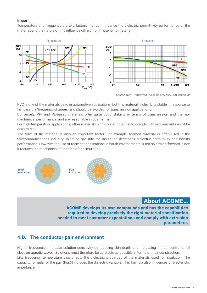
In useTemperature and frequency are two factors that can influence the dielectric permittivity performance of the material, and the nature of this influence differs from material to material.
Source: web – https://en.wikipedia.org/wiki/Film_capacitor
PVC is one of the materials used in automotive applications, but this material is clearly unstable in response to temperature/frequency changes, and should be avoided for transmission applications.Conversely, PP- and PE-based materials offer quite good stability in terms of transmission and thermo- mechanical performance, and are reasonable in cost terms.For high temperature applications, other materials with greater potential to comply with requirements must be considered. The form of the material is also an important factor. For example, foamed material is often used in the telecommunications industry. Injecting gas into the insulation decreases dielectric permittivity and boosts performance. However, the use of foam for applications in harsh environments is not so straightforward, since it reduces the mechanical properties of the insulation.
About ACOME…ACOME develops its own compounds and has the capabilities required to develop precisely the right material specification
needed to meet customer expectations and comply with extrusion parameters.
4.D. The conductor pair environment
Higher frequencies increase solution sensitivity by reducing skin depth and increasing the concentration of electromagnetic waves. Solutions must therefore be as stable as possible in terms of their construction.Like frequency, temperature also affects the dielectric properties of the materials used for insulation. The capacity formula for the pair (Fig.6) includes the dielectric variable. This formula also influences characteristic impedance.
Solidinsulation
Foaminsulation
Temperature Frequency

12
Humidity between the two twisted wires can also affect characteristic impedance and transmission. Generally, when another material intervenes between two wires associated with a dielectric material, it will affect both electrical flux and capacity. To avoid such issues, jacketing should be considered when designing the construction of the cable.
When a material is intentionally inserted between wires, as is the case with full solid jacketing, the equivalent dielectric changes. Even where the characteristics of material and its dielectric properties are known, the capacity formula will not provide a sufficient level of reliability, and it will be more difficult to predict outcomes, and a new equivalent permittivity value must be identified.
About ACOME…The ACOME engineering team uses calculation programs
developed in-house, as well as special CAD systems to simulate definitions for more complex solutions.
4.E. Twisted pair assembly
The way in which the twisted pair is assembled is another variable, since the length of twist can affect dimensional, and therefore signal transmission, stability. Twisting wires tightly together results in the insulation of each wire exerting pressure on the other, which can result in dimensional distortions.Wires must be assembled tightly enough to avoid any slackness between the two, but must not be twisted excessively to the point of imposing high levels of mechanical stress or even breakage.
However, too little pressure during the twisting process can generate signal transmission instability if the wires are assembled too loosely.
Fig.10
EH pattern between a parallel pair of similar wires
Sheathing insulation ɛr1
Sheathing material ɛr2
Fig.11
Jacketed pair
Opening
Wire assembly
Source: https://www.st-andrews.ac.uk

www.acome.com 13
Geometric changes can affect capacity by bringing conductors closer together and changing the area of electrical flux transmissions. These changes result not only from pair twisting and pitch length, but also material softness. So material selection is quite important. A short twisting pitch increases the penetration of both materials, as referred to earlier, and changes the distance between conductors. Temperature changes can also modify the properties of materials, so the correct choice of thermoplastic material is important.
About ACOME…ACOME laboratories analyze assemblies, and design and produce
new materials to avoid cable assembly issues.
4.F. Shielding
As the number of in-car electrical and electronic devices increases, each is becoming smaller in size. This miniaturization of devices is a response to the challenge posed by weight reduction. Reducing system size does not reduce the ability of systems to emit electromagnetic waves, and this fact has a direct impact on cable complexity and manufacturing cost. So as more electronics find their way into different areas of cars, the issue of containing electromagnetic interference (EMI) between devices and systems becomes increasingly challenging.Shielding affects efficiency, attenuation, flexibility and cost.The following diagram shows some examples of shielding solutions.
Examples of shielding solutions
20 dB 40 dB 60 dB 80 dB 100 dB 120 dB
Single braid
screen
Double braid
screen
Foiland
braid screen
Foiland
doublebraid
screen
Tube screen
Corrugated tube
Tinnedbraid
screen
Fig.12
Wires pressure

14
Generally speaking, data transmission cables use metal foil (e.g. aluminum) and metal braid (e.g. tinned copper). Shielding efficiency is defined by transfer impedance (mOhms) or screen attenuation (dB).The shielding efficiency of metal foil depends mainly on foil thickness and the assembly method used.
The shielding efficiency of metal braid depends not only on optical recovery but on many factors: number of strands, size of strands, angle, gap size and pitch.Addressing automotive industry specifications means ensuring flexibility by using the smallest-possible braiding strands and angle of twist while guaranty shielding efficiency.
About ACOME…ACOME has many years of expertise in shielding assembly
techniques for telecoms applications, and has developed its own in-house processes and solutions. This same level of expertise
is applied by ACOME Automotive, whose shielding solutions now range from 0.13 mm² to 100 mm² and above.
4.G. Shielding assembly
Given the complexity of wiring architectures, external environment interference and cable-generated internal interference, it is very important to avoid any additional functional issues by considering shielding. The way in which shielding elements are assembled depends mainly on the level of protection required, and may ultimately affect the way the cable behaves, as well as its electrical performances. In data cables, the main issue is crosstalk. Since electromagnetic interference can influence cable and measurement parameters, shielding assemblies must be efficient enough to prevent external electromagnetic interference from affecting the signal traveling through the cable. The shield assembly method can impose additional pressures on twisted wires, which in turn can affect their
Braiding element
Gap
Angle of twist
Fig.13
Shielded twisted pair cable
Fig.14
HV cable (braided shielding)

www.acome.com 15
Shielding proximity affects electrical transmission. This refers, once again, to the proximity effect resulting from the close vicinity of metal shielding elements to the insulated conductor. Asymmetric foil and braid assemblies can also disturbed the distribution of the current.
One solution for avoiding the proximity effect is to separate shielding from conductors.
Frequency will determine the best solution. The higher the frequency, the more geometrically precise and symmetrical the cable must be. This may influence shielding and weight too.
About ACOME…ACOME cross-divisional expertise in the use of different shielding
methods from high-voltage to data cables is well known and respected in its customer industries, and is the result of our ability
to develop our own products in our in- house test laboratory and related facilities.
ShieldingFig.15
Shielded assembly
Fig.16
Asymmetricshielding
Fig.17
Symmetricshielding
16
5. ACOME metrology recommendations
5.A. Different measures for different applications
Cables and components require a range of different measurements, each of which is important because it characterizes a particular type of performance: transmission measurements (in terms of frequency or time), symmetry measurements and EMC measurements.
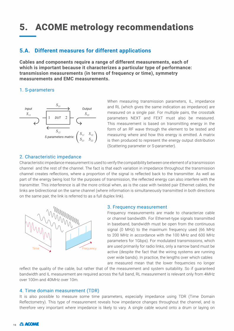
1. S-parameters
When measuring transmission parameters, IL, impedance and RL (which gives the same indication as impedance) are measured on a single pair. For multiple pairs, the crosstalk parameters NEXT and FEXT must also be measured. This measurement is based on transmitting energy in the form of an RF wave through the element to be tested and measuring where and how this energy is emitted. A matrix is then produced to represent the energy output distribution (Scattering parameter or S-parameter).
2. Characteristic impedanceCharacteristic impedance measurement is used to verify the compatibility between one element of a transmission channel and the rest of the channel. The fact is that each variation in impedance throughout the transmission channel creates reflections, where a proportion of the signal is reflected back to the transmitter. As well as part of the energy being lost for the purposes of transmission, the reflected energy can also interfere with the transmitter. This interference is all the more critical when, as is the case with twisted pair Ethernet cables, the links are bidirectional on the same channel (where information is simultaneously transmitted in both directions on the same pair, the link is referred to as a full duplex link).
3. Frequency measurementFrequency measurements are made to characterize cable or channel bandwidth. For Ethernet-type signals transmitted in baseband, bandwidth must be open from the continuous signal (0 MHz) to the maximum frequency used (66 MHz to 200 MHz in accordance with the 100 MHz and 600 MHz parameters for 1Gbps). For modulated transmissions, which are used primarily for radio links, only a narrow band must be active (despite the fact that the wiring systems are running over wide bands). In practice, the lengths over which cablesare measured mean that the lower frequencies no longer
reflect the quality of the cable, but rather that of the measurement and system suitability. So if guaranteed bandwidth and IL measurement are required across the full band, RL measurement is relevant only from 4MHz over 100m and 40MHz over 10m.
4. Time domain measurement (TDR)It is also possible to measure some time parameters, especially impedance using TDR (Time Domain Reflectometry). This type of measurement reveals how impedance changes throughout the channel, and is therefore very important where impedance is likely to vary. A single cable wound onto a drum or laying on
Input
S parameters matrix:
DUT
Output
Time Frequency

www.acome.com 17
a bench will show little variation, but this measurement comes into its own when assessing the impact of a connector or a particular routing of a cable when installed in a vehicle (tight curvature, passing though bulkheads or other structures, etc.). It can also be useful for measuring shorter components (typically connectors or short channels). 5. Symmetry measurement
The symmetry parameters, LCL and LCTL (or TCL and TCTL) are measured in terms of frequency, and require a specific setup. Where transmission parameters are measured in symmetrical (or differential) mode, symmetry parameter measurement is hybrid: an asymmetric signal is injected into the system to be measured for symmetry. This measurement is important because the transceivers are sensitive only to the symmetrical mode.The portion of the signal that arrives in asymmetric form is therefore lost to them. Most
importantly, electromagnetic interference usually takes the form of asymmetric energy, so a conversion in the wiring will create symmetrical mode noise to which the receiver will be very sensitive. So symmetry further improves system electromagnetic immunity.
6. EMC measurementAnother measurement is that which characterizes cable EMC performance to quantify the electromagnetic interference generated by the cable in its external environment, and conversely, the susceptibility of the cable to external interference. At low frequencies, the cable is
characterized by its transfer impedance (Zt), and at high frequencies by coupling attenuation (Ac, for the pairs) and screen attenuation (As for single-core coaxial, power and other cables). These measurements are suitable for shielded cables.
7. Eye diagramThe last option is to create an oscilloscope display-based eye diagram. This measurement is not suitable for passive components like cables, connectors or even channels, but for complete systems that include the destination electronic components. This visual test measures the quality of the signal at a given point in the channel by estimating the ease with which a receiver would be able to discriminate between the different signal levels. It is therefore a useful test for electronics and equipment manufacturers. Comparing multiple eye diagram measurements made at different points in the channel and analyzing the results can highlight
the influences imposed by cabling characteristics such as IL, RL or lack of bandwidth in the channel. The latest measurement devices are even able to generate eye diagrams from measurements of these channel characteristics. Nevertheless, this type of measurement requires special provisions, since eye diagram creation is restricted to simplex links. Since twisted pair Ethernet links are full duplex, special transmission modes are required to avoid return signals, together with a test mode capable of generating the right signals from the transmitters used. Additionally, the use of advanced encoding, pre-coders and echo cancelers on modern Ethernet protocols makes direct interpretation of eye diagrams much more difficult. This test is therefore most useful with certain protocols that are best suited to its techniques, but it can be helpful in the diagnosis or validation of certain links.
Eye height
Eye width
Balanced and unbalanced coupled lines
18
5.B. Expert control of measurement processes
Since effective product quality control relies on the ability to compare products and ensure their compatibility with the protocols they will be required to transmit, clearly established measurement methods are essential. Individual measurement methods for transmission parameters or electromagnetic compatibility parameters are defined by the various standardization bodies (IEEE, Open Alliance, IEC, etc.). Compliance with these recommendations is very important, but expertise and the implementation measurement samples are equally essential, especially for unitary components. It must be possible to exclude any other component, and particular care must be taken over implementation and connection to the measuring device. Implementation of electromagnetic compatibility measurements is all the more critical. Poor interpretation or interpretation by an inexperienced person can deliver performance results that are more representative of the implementation than of the product itself.
About ACOME…With its in-depth experience of telecommunication cable quality control
and inspection, ACOME has expert control of all these types of measurement. We also conduct comparative testing campaigns with
research and accreditation laboratories to ensure that the results are consistently repeatable in every laboratory testing environment. This
ensures that measurements are reliable and directly comparable, which in turn forms the basis for finished product reliability. ACOME is also a
member of the standardization groups for these measurement methods in order to stay abreast of best practices and share its experience with the
community.
In order to accurately reflect the intrinsic qualities of each component, the measurement methods are adapted to suit each type of component, and therefore vary from one type to another. Individual measurements must be made of complete channels and the implementation of each channel element. All channel elements must be implemented in accordance with state-of-the-art good practice to ensure the best-possible performance. So, for example, when using differential transmission elements, care must be taken to ensure symmetry throughout the channel and avoid any separation of the two conductors; where this is not the case, overall performance will be completely compromised. Similarly, a shield is properly effective only when connected to each end of the channel, when it defines the boundary of a closed space through which electromagnetic interference cannot pass. Incorrectly connected, shield performance may be completely negated, or in some cases even counterproductive by allowing the shield to act as an antenna collecting all the surrounding environmental interference. Each component must comply fully with state-of-the-art practice to ensure the best-possible performance from the entire system.
About ACOME… ACOME has extensive expertise in all these areas, and produces
reliable measurements that accurately reflect the intrinsic performance of its cables.

www.acome.com 19
6. Product recommendations by ACOME
On the basis of the recommendations made previously in this white paper, and with the constant focus of delivering high-reliability, high-quality solutions, ACOME believes the twisted pair solution shown below to be compliant with actual 100Mbps and 1Gbps Ethernet protocol applications:
Optimum definition is essential to avoid excessively high solution quality; the ultimate aim being to define the right product for the right requirement, in which case it is clearly very important to understand the benefits delivered by each solution.
Constructiontype
Visualmodel Advantages Disadvantages
UTP
Standard twisted pair No stability
ACOME SIP (Steady Impedance Pair)
Stable geometry even if no jacket
Lightest solutionConnection issue
J-UTP
Tubular Jacket + Standard twisted pair
Lighter solution compared to pressure jacket
Potential signal disturbance due to loose between wires even if jacketed
Could not fil to sealed application
Pressure Jacket + Standard twisted pair Alternative to pressure jacket Additional part
Pressure Jacket + Standard twisted pair +Tape
Stable geometry/signal Heaviest J-UTP solution
STP
Pressure Jacket + Braid + Foil + Standard twisted pair
Solution for high frequency use
Lowest dimensionHigh conversion mode
Pressure Jacket + Braid + Foil + Pressure Material + Standard twisted pair
Stable definition
Lower conversion modeHeaviest J-UTP solution
The product definition concept is dependent on multiple parameters, and ACOME has formulated a number of recommendations based on lessons learnt from its telecom and automotive industry experience and the new challenges of data transmission.In terms of conductors, the recommendation is to use bare copper or copper alloy wherever possible and feasible for the application concerned.
J-UTPJacketed-Unshielded Twisted Pair (0.35mm²/013mm²)
STPShielded Twisted Pair (0.35mm²/0.13mm²)
20
As specified earlier, tinned copper should be considered for designs where particular technical issues apply. In terms of dimensional considerations, greater regularity of shape and the need to handle higher frequencies of use, ACOME has defined the following levels:
• Compressed strand conductor• Semi-Compacted strand conductor (shaped and assembled strands)• Solid conductor (as currently used in today’s telecoms applications)
In terms of insulation, additional materials or jackets, the most important parameter is dielectric properties. The dielectric characteristics of a material and its behavior under different conditions are the determining factors for correct selection.So for today’s automotive applications, the recommendation is to use a material with good stability characteristics, such as PE or PP, wherever feasible. These materials are, of course, limited to the standard temperature range of up to 105°C/125°C.Under other conditions, consideration should be given to the use of special materials compatible with any requirement to operate at higher temperatures.Once the conductor and material have been specified, it is time to consider their assembly.The first consideration is the type of cable to be produced, because as we have seen, other elements intervening between and/or around conductors can affect signal quality. This combination can generate additional complexity, requiring the use of specialist resources, such as CAD tools to simulate the correct cable dimensions and proximity effects.As we have seen earlier in this white paper, it is important to bear in mind the effects produced as a result of assembling wires in terms of their concentricity, thickness and softness, all of which have the potential to affect pair stability and the electrical signal carried.Finally, shielding must be designed such that the cable delivers a sufficient level of performance, at the same time as avoiding any transfer of interference signals.
About ACOME...ACOME is clearly aware of, and familiar with all these challenges as a result of its very high level of involvement with the telecoms
industry, to which it has been supplying twisted pair solutions for more than 85 years. Its cutting-edge engineering expertise and multi-industry positioning together mean that ACOME has the capability required to deliver precisely those custom-made
solutions that meet and exceed customer expectations.
Please do not hesitate to contact us with any questions you may have.


Réf.
09/2
021
– v
2. A
s pa
rt o
f im
prov
ing
the
perf
orm
ance
of i
ts p
rodu
cts,
AC
OM
E re
serv
es th
e rig
ht to
cha
nge
thes
e sp
ecifi
catio
ns w
ithou
t prio
r not
ice.
A
CO
ME,
Soc
iété
Coo
péra
tive
et P
artic
ipat
ive,
a F
renc
h co
oper
ativ
e m
anuf
actu
ring
com
pany
with
var
iabl
e ca
pita
l. Re
gist
ered
off
ice:
52
rue
du M
ontp
arna
sse
- 750
14 P
aris
- Fr
ance
. RC
S Pa
ris B
562
.123
.513
Sire
t 562
123
513
000
45An
y co
pyin
g, re
prod
uctio
n or
dis
trib
utio
n of
this
whi
te p
aper
con
tent
with
out t
he w
ritte
n pe
rmis
sion
of A
CO
ME
Gro
up is
str
ictly
pro
hibi
ted.
52 rue du Montparnasse75014 Paris - FranceT. +33 1 42 79 14 00 www.acome.com