Embed Size (px)
Citation preview
Automotive Ethernet:The Definitive Guide
Charles M. Kozierok Colt Correa
Robert B. Boatright Jeffrey Quesnelle
Illustrated by Charles M. Kozierok, Betsy Timmer, Matt Holden, Colt Correa & Kyle Irving Cover by Betsy Timmer
Designed by Matt Holden

Automotive Ethernet: The Definitive Guide. Copyright © 2014 Intrepid Control Systems.
All rights reserved. No part of this work may be reproduced or transmitted in any form or by any means, electronic or mechanical, including photocopying, recording, or by any information storage or retrieval system, without the prior written permission of the copyright owner and publisher.
Printed in the USA.
ISBN-10: 0-9905388-0-XISBN-13: 978-0-9905388-0-6
For information on distribution or bulk sales, contact Intrepid Control Systems at (586) 731-7950. You can purchase the paperback or electronic version of this book at www.intrepidcs.com or on Amazon. We’d love to hear your feedback about this book—email us at [email protected].
Product and company names mentioned in this book may be the trademarks of their respective owners. Rather than use a trademark symbol with every occurence of a trademarked name, we are using the names only in an editorial fashion and to the benefit of the trademark owner, with no intention of infringement of the trademark.
The information in this book is distributed on an “As Is” basis, without warranty. While every precaution has been taken in the preparation of this book, neither the authors nor Intrepid Control Systems shall have any liability to any person or entity with respect to any loss or damage caused or alleged to be caused directly or indirectly by the information contained in this book.

v© 2014 Intrepid Control Systems. All Rights Reserved. [email protected] • www.intrepidcs.com
Forewordby Bob Metcalfe, Inventor of Ethernet
Automotive Ethernet—If You Build It, They Will ComeThe early Internet of 1969 ran across transcontinental trunks at 50 kilobits per second, creating what we might dub the Kilobit Internet. Advances such as fiber optics and dense wave-division multiplexing (DWDM) in the 1990s brought us forward to the Megabit Internet of today. What’s next? We network plumbers are now “gigifying” the Internet, with the Gigabit Internet promising incredible performance beyond anything most Internet users can dream of today.
But what will all this power be used for?We envision that new technologies will not only expand the Internet’s speed, but also
broaden its scope. The Internet of Things (IoT) will bring device connectivity on a scale unimaginable even given the current Internet’s enormous size, making good use of those gigabit connections. And another place where I see the Internet becoming ubiquitous is in the billions of microcontrollers used in modern automobiles, especially as we add new safety, convenience and entertainment capabilities, and eventually move toward driverless transportation for greater safety and efficiency.
Many people don’t realize that modern cars are already heavily networked, and becoming more so every day. Planners foresee no fewer than four kinds of automotive networking in the future:

vi © 2014 Intrepid Control Systems. All Rights Reserved. [email protected] • www.intrepidcs.com
1. Networking within cars, to implement systems control, driver feedback, safety features, entertainment and many other functions.
2. Networking between cars, to implement capabilities such as collision avoidance.3. Networking between cars and the road infrastructure, for greater safety and
efficiency.4. Networking from cars to the Internet, to allow passengers to get driving-related
information such as maps and traffic updates in a timely manner, or simply to remain part of our always-connected world.
Automobile networks are currently mostly focused on the first category—in-vehicle systems—which are presently implemented using relatively slow technologies not found outside the automotive industry. As the inner workings of cars become more intelligent and complex, they increasingly demand improvements in the networking area. But any new technology used here needs to be not just faster, cheaper, and capable of connecting many nodes—it also needs to be standardized and widely adopted, to enable compatibility and connectivity among diverse suppliers and industries.
As I have been saying for 40 years: “If it’s networking that you need, Ethernet is the answer; what is the question?” In this case, we there might be consider two related questions: “What took the automotive world so long? And how will it now use Ethernet going forward?”. This book provides the answers to these questions.
Ethernet comprises much of the Internet’s packet plumbing, and its reach is enormous. It has also been evolving rapidly since its invention as a personal computer LAN back on May 22, 1973, and doing so quite successfully as a set of open standards under IEEE Project 802. It has also been adapted from wired to wireless in the form of Wi-Fi, also known as “wireless Ethernet”, which will play a key role in external automotive networking in the future. More than a billion wired and wireless (Wi-Fi) Ethernet ports now ship annually, and the automotive industry represents the potential for this number to increase significantly.
This book is about Ethernet, and how its many advantages and innovations will move in-car networking to the next level, setting the stage for a true revolution in the capabilities of vehicles and how we use them. It provides essential reference material for the intersection of the automotive networking world and the Ethernet world, and points the way to the future of the connected vehicle. It is a guide to the next big thing in the Gigabit Internet: Automotive Ethernet.
Bob MetcalfeInventor of Ethernet TechnologyProfessor of Innovation, Murchison Fellow of Free EnterpriseUniversity of Texas at Austin


TABLE OF CONTENTS
PART I: INTRODUCTION TO GENERAL AND AUTOMOTIVE NETWORKING .............. 1
Chapter 1: The Motivation for Automotive Ethernet: Advantages and Opportunities ............. 3
1.1 Introduction ............................................................................................................................................................................................... 31.2 Two Worlds Collide ............................................................................................................................................................................... 41.3 Automotive Electronics - A Market for Growth ................................................................................................................... 51.4 Ethernet - An Ocean of Possibilities ............................................................................................................................................ 71.5 Increasing Bandwidth and Future-Proof Technology ........................................................................................................... 81.6 Full-Duplex, Packet-Switched, Address-Based Networking ...........................................................................................101.6.1 Full-Duplex Operation .................................................................................................................................................................101.6.2 Packet Switching ..............................................................................................................................................................................111.6.3 Address-Based Messaging ...........................................................................................................................................................111.7 Electrical Isolation ................................................................................................................................................................................131.8 Power over Ethernet (PoE) and Power over Data Lines (PoDL) ..............................................................................141.9 High Speed and Low Weight ...........................................................................................................................................................151.10 Product Differentiation - It’s No Longer About Nuts and Bolts ................................................................................161.11 Wireless Functionality........................................................................................................................................................................171.12 Summary ....................................................................................................................................................................................................18
Chapter 2: Overview, Background and Business Requirements of Automotive Networking ..........................................................................................................................................................................19
2.1 Introduction .............................................................................................................................................................................................192.2 A Brief History of Automotive Networking ..........................................................................................................................202.2.1 The First Serial Communications ............................................................................................................................................202.2.2 Real-Time Networks ....................................................................................................................................................................212.2.3 Establishing CAN as an Industry Standard .........................................................................................................................222.2.4 Beyond CAN ....................................................................................................................................................................................222.2.5 The Dawn of Automotive Ethernet ......................................................................................................................................232.3 Safety ...........................................................................................................................................................................................................242.3.1 The Double Edged Sword of Automotive Electronics ...............................................................................................252.3.2 ISO 26262 - Road Vehicle Safety Standard for Electrical and Electronic Systems ..........................................282.3.3 Automotive Safety Integrity Level (ASIL) ...........................................................................................................................282.3.4 Achieving Functional Safety .......................................................................................................................................................292.4 Component Availability......................................................................................................................................................................292.4.1 Contrasting the Average Lifespan of Consumer Electronics and Vehicles ..........................................................302.4.2 The Development Cycle of Consumer Electronics Compared to Automobiles ............................................312.4.3 Summary of Important Factors for Component Availability .....................................................................................322.5 Cost Considerations ...........................................................................................................................................................................332.5.1 Electronics Content in a Modern Vehicle............................................................................................................................33
x
Automotive Ethernet: The Definitive Guide
© 2014 Intrepid Control Systems. All Rights Reserved. [email protected] • www.intrepidcs.com
2.5.2 ProfitMarginsforAutomotiveManufacturers .................................................................................................................342.5.3 Changing Times Mean New Cost Equations in the Networking World .............................................................35
Chapter 3: Electrical Requirements for Automotive Electronics .................................................................37
3.1 Power Supply / Voltages .....................................................................................................................................................................373.1.1 Reverse Polarity ...............................................................................................................................................................................383.1.2 Cold Cranking Voltage ..................................................................................................................................................................383.1.3 Load Dump .......................................................................................................................................................................................403.1.4 Power Management ......................................................................................................................................................................403.1.5 Parked State Power Consumption (Parasitic Current Draw) ..................................................................................433.1.6 Power Connections to an ECU ...............................................................................................................................................453.1.7 Automotive Transceivers .............................................................................................................................................................463.1.8 Typical System Sleep / Standby Modes ................................................................................................................................483.1.9 Wakeup / Boot Time ....................................................................................................................................................................513.1.10 Virtual Networking ........................................................................................................................................................................523.1.11 Partial Networking .........................................................................................................................................................................523.2 Electromagnetic Compatibility ......................................................................................................................................................563.2.1 Emissions Testing .............................................................................................................................................................................563.2.2 Immunity (Susceptibility) Testing ..............................................................................................................................................59
Chapter 4: Environmental and Mechanical Requirements for Automotive Electronics ........65
4.1 Environmental Concerns ..................................................................................................................................................................654.1.1 Constant Temperature Conditions .........................................................................................................................................674.1.2 Temperature Fluctuations and Temperature Step Testing ...........................................................................................674.1.3 Temperature Cycling .....................................................................................................................................................................684.1.4 Ice Water Shock Testing ...............................................................................................................................................................694.1.5 Salt Spray ............................................................................................................................................................................................704.1.6 Cyclic Humid Heat .......................................................................................................................................................................714.1.7 Dust .......................................................................................................................................................................................................714.2 Mechanical Loads / Vibrations ........................................................................................................................................................724.2.1 Thermal Impact of Mechanical Loads ...................................................................................................................................734.2.2 Free Fall / Drop Test ....................................................................................................................................................................734.2.3 Vehicle Body / Sprung Masses ..................................................................................................................................................734.2.4 Wheels, Suspension / Unsprung Masses .............................................................................................................................744.2.5 Doors, Hood and Trunk ..............................................................................................................................................................754.2.6 Engine ...................................................................................................................................................................................................754.2.7 Transmission or Gearbox ...........................................................................................................................................................764.2.8 Flexible Plenum Chamber ..........................................................................................................................................................76
Chapter 5: Networking Fundamentals .....................................................................................................................................79
5.1 Introduction .............................................................................................................................................................................................795.2 Fundamental Network Characteristics ....................................................................................................................................805.2.1 Networking Layers, Models and Architectures ................................................................................................................805.2.2 Protocols: What Are They, Anyway? .......................................................................................................................................825.2.3 Circuit Switching and Packet Switching Networks .........................................................................................................84
xi
Table of Contents
© 2014 Intrepid Control Systems. All Rights Reserved. [email protected] • www.intrepidcs.com
5.2.4 Connection-Oriented and Connectionless Protocols ..................................................................................................865.2.5 Messages: Packets, Frames, Datagrams and More ...........................................................................................................885.2.6 Message Formatting: Headers, Payloads and Footers ...................................................................................................895.2.7 Message Addressing and Transmission Methods: Unicast, Broadcast and Multicast Messages ..................915.2.8 Network Topologies ......................................................................................................................................................................945.2.9 Network Operational Models and Roles: Peer-to-Peer, Client/Server and Master/Slave Networking .985.3 Types and Sizes of Networks ...................................................................................................................................................... 1035.3.1 Local Area Networks (LANs), Wireless LANs (WLANs), Wide Area Networks (WANs) and Variants ..................................................................................................................................................................................... 1035.3.2 Network Size Terminology: Segments, Clusters, Networks, Subnetworks and Internetworks ..............1065.3.3 The Internet, Intranets and Extranets ................................................................................................................................ 1095.4 Network Performance Issues and Concepts ..................................................................................................................... 1105.4.1 Putting Network Performance In Perspective ............................................................................................................... 1105.4.2 Balancing Network Performance with Key Non-Performance Characteristics .............................................1115.4.3 Understanding Performance Measurement Terms and Units ................................................................................ 1125.4.4 Performance Dimensions: Speed, Bandwidth, Throughput and Latency ...........................................................1155.4.5 Theoretical and Real-World Throughput, and Factors Affecting Network Performance .........................1185.4.6 Simplex, Half-Duplex and Full-Duplex Communication ........................................................................................... 1205.4.7 Quality of Service (QoS) ......................................................................................................................................................... 122
Chapter 6: Automotive Ethernet Related Standards Organizations and Associations ......125
6.1 Introduction .......................................................................................................................................................................................... 1256.2 Making Sense of Standards Organizations and Associations ...................................................................................... 1266.3 International Standards Organizations ................................................................................................................................... 1276.3.1 International Organization for Standardization (ISO) ................................................................................................ 1276.3.2 International Electrotechnical Commission (IEC) ........................................................................................................ 1286.3.3 Institute for Electronics and Electrical Engineers (IEEE) ............................................................................................ 1296.3.4 Internet Engineering Task Force (IETF) .............................................................................................................................. 1316.3.5 SAE International ......................................................................................................................................................................... 1326.4 Industry Consortiums and Associations ............................................................................................................................... 1336.4.1 One-Pair EtherNet (OPEN) Alliance Special Interest Group (SIG) ...................................................................1336.4.2 AVnu Alliance ................................................................................................................................................................................ 1346.4.3 Association for Standardization of Automation and Measuring Systems (ASAM) ......................................1346.4.4 AUTOSAR ...................................................................................................................................................................................... 135
Chapter 7: The Open System Interconnection (OSI) Reference Model ...............................................137
7.1 Introduction .......................................................................................................................................................................................... 1377.2 History of the OSI Reference Model...................................................................................................................................... 1387.3 General Reference Model Issues............................................................................................................................................... 1387.3.1 TheBenefitsofNetworkingModels.................................................................................................................................. 1397.3.2 Why Understanding The OSI Reference Model Is Important To You ................................................................1407.3.3 The OSI Reference Model in the “Real World” ........................................................................................................... 1407.3.4 The OSI Reference Model and Other Networking Models, Protocol Suites and Architectures .........1417.4 Key OSI Reference Model Concepts ...................................................................................................................................... 1417.4.1 OSI Reference Model Networking Layers, Sublayers and Layer Groupings ...................................................1417.4.2 “N” Notation and Other OSI Model Layer Terminology ......................................................................................... 1447.4.3 Interfaces: Vertical (Adjacent Layer) Communication ................................................................................................ 146

xii
Automotive Ethernet: The Definitive Guide
© 2014 Intrepid Control Systems. All Rights Reserved. [email protected] • www.intrepidcs.com
7.4.4 Protocols: Horizontal (Corresponding Layer) Communication ............................................................................ 1487.4.5 Data Encapsulation, Protocol Data Units (PDUs) and Service Data Units (SDUs) ...................................1507.4.6 Indirect Device Connection and Message Routing ..................................................................................................... 1537.5 OSI Reference Model Layers ....................................................................................................................................................... 1567.5.1 Physical Layer (Layer 1) ............................................................................................................................................................ 1567.5.2 Data Link Layer (Layer 2) ........................................................................................................................................................ 1587.5.3 Network Layer (Layer 3) ......................................................................................................................................................... 1607.5.4 Transport Layer (Layer 4) ....................................................................................................................................................... 1617.5.5 Session Layer (Layer 5) ............................................................................................................................................................. 1647.5.6 Presentation Layer (Layer 6) .................................................................................................................................................. 1657.5.7 Application Layer (Layer 7) .................................................................................................................................................... 1657.6 OSI Reference Model Layer Summary ................................................................................................................................... 166
Chapter 8: Comparing Traditional Automotive Networks to Ethernet ................................................169
8.1 Introduction .......................................................................................................................................................................................... 1698.2 Ethernet .................................................................................................................................................................................................. 1708.2.1 Background ..................................................................................................................................................................................... 1718.2.2 Physical Layer ................................................................................................................................................................................. 1718.2.3 Topology .......................................................................................................................................................................................... 1758.2.4 Frame Format ................................................................................................................................................................................ 1778.2.5 Media Access Control .............................................................................................................................................................. 1798.2.6 Advantages .................................................................................................................................................................................... 1808.2.7 Disadvantages ................................................................................................................................................................................ 1808.3 Controller Area Network (CAN) and CAN with Flexible Data Rate (CAN-FD) .......................................1818.3.1 Background ..................................................................................................................................................................................... 1818.3.2 Physical Layer ................................................................................................................................................................................. 1828.3.3 Topology ......................................................................................................................................................................................... 1828.3.4 Messaging / Frame Format .................................................................................................................................................... 1838.3.5 Media Access Control .............................................................................................................................................................. 1858.3.6 A Note on CAN-FD ................................................................................................................................................................ 1868.3.7 Advantages .................................................................................................................................................................................... 1868.3.8 Disadvantages ................................................................................................................................................................................ 1878.4 FlexRay ................................................................................................................................................................................................... 1878.4.1 Background ..................................................................................................................................................................................... 1888.4.2 Topology .......................................................................................................................................................................................... 1888.4.3 Messaging / Frame Format ...................................................................................................................................................... 1898.4.4 Media Access Control .............................................................................................................................................................. 1918.4.5 Advantages .................................................................................................................................................................................... 1938.4.6 Disadvantages ................................................................................................................................................................................ 1938.5 Media Oriented Serial Transport (MOS T) ........................................................................................................................... 1938.5.1 Background ..................................................................................................................................................................................... 1948.5.2 Physical Layer(s) ........................................................................................................................................................................... 1948.5.3 Topology .......................................................................................................................................................................................... 1958.5.4 Messaging / Frame Format .................................................................................................................................................... 1968.5.5 Media Access Control .............................................................................................................................................................. 1978.5.6 Advantages .................................................................................................................................................................................... 1978.5.7 Disadvantages .............................................................................................................................................................................. 1978.6 Local Interconnect Network (LIN) ......................................................................................................................................... 198

xiii
Table of Contents
© 2014 Intrepid Control Systems. All Rights Reserved. [email protected] • www.intrepidcs.com
8.6.1 Background ..................................................................................................................................................................................... 1988.6.2 Physical Layer ................................................................................................................................................................................. 1998.6.3 Topology .......................................................................................................................................................................................... 1998.6.4 Messaging / Frame Format .................................................................................................................................................... 1998.6.5 Media Access Control .............................................................................................................................................................. 2018.6.6 Advantages .................................................................................................................................................................................... 2018.6.7 Disadvantages .............................................................................................................................................................................. 2018.7 Summary Comparison of Automotive Network Technologies................................................................................. 201
PART II: AN OVERVIEW OF ETHERNET ARCHITECTURE, OPERATION AND HARDWARE ...........................................................................................................................................................................205
Chapter 9: Overview of IEEE Project 802 and Ethernet (IEEE 802.3) .................................................207
9.1 A Short History of Ethernet ....................................................................................................................................................... 2079.2 IEEE Project 802 Structure, Networking Model, Standards and Working Groups ........................................2109.2.1 History and Evolution of IEEE Project 802 ..................................................................................................................... 2109.2.2 Structure of the IEEE 802 LAN/MAN Standards Committee (LMSC) ............................................................2119.2.3 Overview of the IEEE Project 802 Standards Development Process ...............................................................2129.2.4 The IEEE Project 802 Networking Model and Extensions to the OSI Reference Model .......................2149.2.5 Summary of IEEE 802 Working Groups ........................................................................................................................... 2169.3 IEEE 802.1 - Project 802 Architecture, Management, Internetworking, and Higher Layer Interfaces .2199.3.1 Working Group Mission, Responsibilities and Task Groups .................................................................................... 2199.3.2 IEEE 802.1 Standard Naming Conventions ..................................................................................................................... 2209.3.3 Major IEEE 802.1 Standards.................................................................................................................................................... 2219.4 IEEE 802.2 - Logical Link Control (LLC) ............................................................................................................................... 2239.4.1 IEEE 802.2 Overview and Role - Theory and Practice ............................................................................................. 2239.4.2 IEEE 802.2 Logical Link Control Service Types .............................................................................................................. 2249.4.3 IEEE 802.2 Link Service Access Points (SAPs) ............................................................................................................... 2259.4.4 IEEE 802.2 Logical Link Control Subheader and Source and Destination SAPs (SSAPs and DSAPs) ................................................................................................................................................................... 2269.4.5 IEEE 802.2 Subnetwork Access Protocol (SNAP) and SNAP Subheaders ....................................................2279.5 IEEE 802.3 - Ethernet Overview ............................................................................................................................................... 2289.5.1 Ethernet Standards and Architecture ................................................................................................................................ 2289.5.1.1 Early(Pre-IEEE)EthernetSpecifications .............................................................................................................................. 2299.5.1.2 IEEE 802.3 Ethernet Standards............................................................................................................................................... 2309.5.1.3 Overall IEEE 802.3 (Ethernet) Architecture ........................................................................................................................ 2349.5.1.4 The Ethernet MAC-PHY Interface - Media Independent Interfaces (MIIs) and the Reconciliation Sublayer (RS) ................................................................................................................................................... 2359.5.2 Overview of the Elements of an Ethernet Network ................................................................................................. 2379.5.2.1 Network Devices (End Devices, Hosts) .............................................................................................................................. 2379.5.2.2 Media (Cable) Types and Connection Topologies .............................................................................................................. 2389.5.2.3 Network Interconnection Devices ....................................................................................................................................... 2409.5.2.4 Physical Layer Encoding and Signaling Methods ................................................................................................................. 2419.5.2.5 Media Access Control (MAC) Methods .............................................................................................................................. 2429.5.2.6 Ethernet Frames (Messages) .................................................................................................................................................. 242

xiv
Automotive Ethernet: The Definitive Guide
© 2014 Intrepid Control Systems. All Rights Reserved. [email protected] • www.intrepidcs.com
9.5.3 Ethernet Speed Families ........................................................................................................................................................... 2439.5.3.1 Regular Ethernet (10 Mb/s) and Low-Speed Ethernet (1 Mb/s) ................................................................................... 2439.5.3.2 Fast Ethernet (100 Mb/s) ........................................................................................................................................................ 2449.5.3.3 Gigabit Ethernet (1 Gb/s) ....................................................................................................................................................... 2459.5.3.4 Faster Ethernet Speeds (10-Gigabit, 40-Gigabit, 100-Gigabit and 400-Gigabit Ethernet) ........................................2469.5.4 Overview of Ethernet Performance-Enhancing and Special Features ...............................................................2479.5.4.1 Switched (Contentionless) Ethernet .................................................................................................................................... 2479.5.4.2 Full-Duplex Transmissions........................................................................................................................................................ 2489.5.4.3 Multiple Speed Networks and Auto-Negotiation ............................................................................................................. 2499.5.4.4 Jumbo Frames ............................................................................................................................................................................ 2509.5.4.5 Link Aggregation ........................................................................................................................................................................ 2509.5.4.6 Virtual LANs .............................................................................................................................................................................. 2519.5.4.7 Power over Ethernet (PoE)..................................................................................................................................................... 2519.5.4.8 Energy-EfficientEthernet(EEE) ............................................................................................................................................. 252
Chapter 10: Ethernet (IEEE 802.3) Physical Layer — Encoding, Signaling and Cabling Specifications ............................................................................................................................................................................ 253
10.1 Ethernet Physical Layer Notation ............................................................................................................................................. 25410.2 Physical Layer Architecture of Fast (100 Mb/s) Ethernet and Gigabit (1 Gb/s) Ethernet .........................25610.2.1 Overall Fast Ethernet and Gigabit Ethernet Physical Layer Architecture .........................................................25710.2.2 Ethernet Physical Coding Sublayer (PCS) ........................................................................................................................ 25810.2.3 Ethernet Physical Medium Attachment (PMA) Sublayer .......................................................................................... 25910.2.4 Physical Medium Dependent (PMD) Sublayer .............................................................................................................. 26010.2.5 Medium Dependent Interface (MDI) and Physical Medium ................................................................................... 26110.3 General Ethernet Physical Layer Issues, Responsibilities and Features ................................................................26210.3.1 The Physical Layer “Trade-off Triangle” - Cable Length, Transmission Speed and Implementation Cost ................................................................................................................................................................. 26210.3.2 Factors Affecting Cable Length ............................................................................................................................................. 26410.3.3 High-Level Encoding and Processing - Block Coding and Scrambling ...............................................................26510.3.4 Low-Level Line Coding and Digital Signal Processing ................................................................................................ 26810.3.5 Auto-Negotiation ........................................................................................................................................................................ 27210.4 Overview of Fast (100 Mb/s) Ethernet and Gigabit (1 Gb/s) Ethernet Physical Layers ..............................27510.4.1 Summary of Regular (10 Mb/s) Ethernet Physical Layer Interfaces (10BASE5, 10BASE2, 10BASE-T, FOIRL, 10BASE-F) ................................................................................................................................................ 27510.4.2 Fast Ethernet Physical Layer Interfaces (100BASE-FX, 100BASE-TX, 100BASE-T4, 100BASE-T2) ...27910.4.3 Gigabit Ethernet Physical Layer Interfaces (1000BASE-SX, 1000BASE-LX, 1000BASE-CX, 1000BASE-T) ................................................................................................................................................................................. 28610.5 BroadR-Reach / OABR / One Twisted Pair 100 Mb/s Ethernet (1TPCE) Physical Layer / IEEE P802.3bw (100BASE-T1) .................................................................................................................................................... 29310.5.1 Design Goals of BroadR-Reach ............................................................................................................................................ 29410.5.2 BroadR-Reach Physical Layer Architecture and Relationship to 1000BASE-T Gigabit Ethernet ..........29610.5.3 General Characteristics - Topology, Throughput and Media Access Control Method ...............................29710.5.4 Physical Coding Sublayer (BR-PCS) Operation and High-Level Encoding Methods ..................................29810.5.5 Physical Medium Attachment Sublayer (BR-PMA) Operation and Low-Level Coding and Signaling Methods ........................................................................................................................................................................ 30110.5.6 Cable and Connectors .............................................................................................................................................................. 30110.5.7 IEEE Standardization Process ................................................................................................................................................. 30210.6 Reduced Twisted Pair Gigabit Ethernet (RTPGE) / IEEE P802.3bp (1000BASE-T1) .....................................303
xv
Table of Contents
© 2014 Intrepid Control Systems. All Rights Reserved. [email protected] • www.intrepidcs.com
Chapter 11: Ethernet (IEEE 802.3) Media Access Control (MAC) Sublayer: Addressing, Transmission Methods, Frame Formats and Special Features.................................305
11.1 Ethernet Media Access Control (MAC) Addresses ......................................................................................................... 30611.1.1 MAC Addressing Overview ................................................................................................................................................... 30711.1.2 Universally Administered MAC Addresses ...................................................................................................................... 30711.1.3 Locally Administered Addresses ........................................................................................................................................... 30911.1.4 Broadcast, Group and Virtual MAC Addresses ............................................................................................................. 31011.1.5 Canonical and Non-Canonical MAC Address Formats ............................................................................................ 31111.2 Overview of the Traditional Shared Medium Ethernet Media Access Control (MAC) Method ............31311.2.1 The Carrier Sense Multiple Access with Collision Detection (CSMA/CD) Mechanism ..........................31311.2.2 CSMA/CD Collisions, Collision Handling and Jam Patterns.................................................................................... 31411.2.3 Ethernet Slot Time and Its Impact on Ethernet Characteristics............................................................................ 31611.2.4 Ethernet Collision Resolution: Backing Off and the Truncated Binary Exponential Backoff (TBEB) Algorithm ........................................................................................................................................................................ 31811.2.5 Gigabit Ethernet Media Access Control Changes: Carrier Extension and Frame Bursting .....................32011.3 Dedicated (Contentionless, Switched) and Full-Duplex Ethernet .......................................................................... 32211.3.1 Problems and Limitations with Half-Duplex Ethernet and CSMA/CD.............................................................32211.3.2 Dedicated (Contentionless) Ethernet: The Basics of Switched, Collision-Free Operation ......................32511.3.3 Full-Duplex Ethernet .................................................................................................................................................................. 32811.4 Standard Ethernet Frame and Packet Formats and Transmission Delimiters ...................................................33011.4.1 The Preamble, Start Frame Delimiter and Interframe Gap .................................................................................... 33111.4.2 Overview of Ethernet Frames and Packets .................................................................................................................... 33211.4.3 The History Behind Ethernet’s Different Standard Frame Formats ...................................................................33311.4.4 DIX Ethernet (Ethernet II) Frame Format and Ethertypes .................................................................................... 33411.4.5 IEEE 802.3+802.2 Ethernet Frame Format..................................................................................................................... 33711.4.6 IEEE 802.3+802.2+SNAP Ethernet Frame Format .................................................................................................... 33911.5 Special Ethernet Features and Frame Formats .................................................................................................................. 34211.5.1 Ethernet Flow Control, MAC Control Frames and Pause Frames ......................................................................34211.5.2 Ethernet Virtual LANs (VLANs), Frame Priority and Ethernet Frame Tagging ..............................................34511.5.3 Ethernet Frame Size Extension (Jumbo Frames) ......................................................................................................... 350
Chapter 12: Ethernet Hardware: Media (Cables and Connectors), Controllers, Hosts and Interconnection Devices (Including Bridges and Switches) ................................................353
12.1 Ethernet Media - Cables and Connectors ........................................................................................................................... 35412.1.1 Overview of Cable Performance and Quality Characteristics and Ratings ....................................................35412.1.1.1 Bandwidth, Frequency and Data Carrying Capacity.......................................................................................................... 35512.1.1.2 Power, Attenuation and Insertion Loss ................................................................................................................................. 35712.1.1.3 Impedance, Characteristic Impedance and Bus Termination ........................................................................................... 35912.1.1.4 Impedance Matching and Return Loss ................................................................................................................................. 36012.1.1.5 Interference, Noise, and Signal-to-Noise Ratio (SNR) ..................................................................................................... 36112.1.1.6 Crosstalk (NEXT, PS NEXT, FEXT, ELFEXT and PS ELFEXT) ......................................................................................... 36312.1.1.7 Alien Crosstalk ........................................................................................................................................................................... 36512.1.1.8 Attenuation to Crosstalk Ratio (ACR) ................................................................................................................................. 36612.1.1.9 Nominal Velocity of Propagation (NVP) and Cable Length Measurement..................................................................36712.1.1.10 Propagation Delay and Delay Skew .................................................................................................................................... 36712.1.2 Construction and Operation of Twisted Pair (TP) Media........................................................................................ 36812.1.2.1 The Powerful Concept Behind Twisted Pair Media: Balanced / Differential Signaling ................................................368
xvi
Automotive Ethernet: The Definitive Guide
© 2014 Intrepid Control Systems. All Rights Reserved. [email protected] • www.intrepidcs.com
12.1.2.2 Comparing Twisted Pair Cables to Other Networking Media........................................................................................ 37012.1.2.3 Characteristics of Twisted Pairs - Conductor Material and Type, Pair Twist Rate, Insulation and Pair Shielding ...37112.1.2.4 Characteristics of Standard (Four-Pair) Twisted Pair Cables: Cable Jacket Materials, Shielding, Internal Structures and Overall Construction ................................................................................................................................... 37512.1.2.5 Categorization and Naming of Twisted Pair Cable Based on Shielding ........................................................................ 37812.1.2.6 Shielding Drawbacks and the Evolution of Twisted Pair Cable in the Networking Industry ....................................37912.1.2.7 Overview of TIA/EIA 568 Cable Categories and ISO/IEC 11801 Classes for Twisted Pair Cable .........................38012.1.2.8 Standard Twisted Pair Ethernet 8P8C (RJ-45) Connectors ............................................................................................. 38312.1.2.9 Twisted Pair Cable in Automotive Ethernet Applications ................................................................................................ 38512.1.2.10 Twisted Pair Connectors in Automotive Ethernet Applications ..................................................................................... 38812.1.3 A Brief Summary of Other Media Types .......................................................................................................................... 39012.1.3.1 Coaxial (Coax) Cable .............................................................................................................................................................. 39112.1.3.2 Twinaxial (Twinax) Cable......................................................................................................................................................... 39112.1.3.3 Fiber Optic Cable...................................................................................................................................................................... 39212.2 Ethernet Controllers and Hosts................................................................................................................................................ 39612.2.1 Ethernet Controllers .................................................................................................................................................................. 39612.2.2 Ethernet Hosts .............................................................................................................................................................................. 39812.2.3 Ethernet Interfaces and Multihoming ................................................................................................................................. 39912.3 Ethernet Interconnection Devices (Including Ethernet Switches) .......................................................................... 40012.3.1 Overview and General Characteristics of Ethernet Interconnection Devices ..............................................40112.3.1.1 Role and Function of Interconnection Devices in Ethernet Networks ........................................................................ 40112.3.1.2 Criteria Differentiating Ethernet Interconnection Devices .............................................................................................. 40212.3.1.3 Collision Domain Segmentation Using Ethernet Interconnection Devices .................................................................40412.3.1.4 Broadcast Domain Segmentation Using Ethernet Interconnection Devices ...............................................................40512.3.2 Fundamental Ethernet Interconnection Devices .......................................................................................................... 40512.3.2.1 Repeaters .................................................................................................................................................................................... 40512.3.2.2 Hubs ............................................................................................................................................................................................. 40612.3.2.3 Bridges ......................................................................................................................................................................................... 40812.3.2.4 Switches ...................................................................................................................................................................................... 41012.3.2.5 Routers ........................................................................................................................................................................................ 41212.3.2.6 Interconnection Device Summary Comparison ................................................................................................................ 41312.3.3 Operation and Features of Ethernet Switches ............................................................................................................. 41412.3.3.1 Overview of Standard “Transparent” Switch Operation - Address-Based Frame Forwarding ...............................41512.3.3.2 The Switch Learning Process ................................................................................................................................................. 41612.3.3.3 Switch Table Updates and Entry Aging ................................................................................................................................. 41612.3.3.4 Store-and-Forward Versus Cut-Through Switching ........................................................................................................... 41712.3.3.5 Buffering, Simultaneous Transfers, and Switching Capacity ............................................................................................... 41912.3.3.6 Switch Expansion, Feature Support, and Management ..................................................................................................... 42012.3.3.7 SwitchTrafficMonitoringIssuesandSolutions ................................................................................................................... 42212.3.3.8 Higher-Layer and Multilayer Switching.................................................................................................................................. 422
PART III: TCP/IP NETWORK LAYER (OSI LAYER 3) PROTOCOLS ....................................427
Chapter 13: Overview of the TCP/IP Protocol Suite and Architecture ..............................................429
13.1 Introduction .......................................................................................................................................................................................... 429
xvii
Table of Contents
© 2014 Intrepid Control Systems. All Rights Reserved. [email protected] • www.intrepidcs.com
13.2 TCP/IP Overview and History ................................................................................................................................................... 43013.3 TCP/IP Services and Client/Server Operation .................................................................................................................. 43313.4 TCP/IP Architecture and the TCP/IP (DARPA/DOD) Model .................................................................................... 43613.5 Summary of Key TCP/IP Protocols .......................................................................................................................................... 439
Chapter 14: Address Resolution and the TCP/IP Address Resolution Protocol (ARP) ....445
14.1 Introduction .......................................................................................................................................................................................... 44514.2 Address Resolution Concepts and Issues ............................................................................................................................ 44614.2.1 The Need For Address Resolution ..................................................................................................................................... 44614.2.2 Address Resolution Through Direct Mapping ............................................................................................................... 44814.2.3 Dynamic Address Resolution ................................................................................................................................................. 45114.2.5 DynamicAddressResolutionCachingandEfficiencyIssues .................................................................................. 45314.3 TCP/IP Address Resolution Protocol (ARP) ....................................................................................................................... 45414.3.1 ARP Overview, Standards and History ............................................................................................................................. 45414.3.2 ARPAddressSpecificationandGeneralOperation .................................................................................................. 45514.3.3 ARP Message Format ................................................................................................................................................................ 45814.3.4 ARP Caching .................................................................................................................................................................................. 46014.3.5 Proxy ARP ....................................................................................................................................................................................... 46214.4 TCP/IP Address Resolution For IP Multicast Addresses............................................................................................... 46414.5 TCP/IP Address Resolution For IP Version 6 ...................................................................................................................... 466
Chapter 15: Introduction to the Internet Protocol (IP) ....................................................................................... 469
15.1 Introduction .......................................................................................................................................................................................... 46915.2 IP Overview and Key Operational Characteristics ......................................................................................................... 47015.3 IP Functions ........................................................................................................................................................................................... 47215.4 IP History, Standards, Versions and Closely-Related Protocols ................................................................................ 473
Chapter 16: IP Addressing ................................................................................................................................................................ 477
16.1 Introduction .......................................................................................................................................................................................... 47716.2 IP Addressing Concepts and Issues .......................................................................................................................................... 47816.2.1 IP Addressing Overview and Fundamentals ................................................................................................................. 47816.2.2 IP Address Size, Address Space and “Dotted Decimal” Notation ...................................................................... 48216.2.3 IP Basic Address Structure and Main Components: Network ID and Host ID ...........................................48316.2.4 IP Addressing Categories (Classful, Subnetted and Classless) and IP Address Adjuncts (Subnet Mask and Default Gateway) ................................................................................................................................. 48616.2.5 Number of IP Addresses and Multihoming ................................................................................................................... 48716.2.6 IP Address Management and Assignment Methods and Authorities ................................................................49016.3 IP “Classful”(Conventional) Addressing ................................................................................................................................ 49116.3.1 IP “Classful” Addressing Overview and Address Classes ........................................................................................ 49116.3.2 IP“Classful”AddressingNetworkandHostIdentificationandAddressRanges ........................................49416.3.3 IP Address Class A, B and C Network and Host Capacities ................................................................................ 49716.3.4 IP Addresses With Special Meanings .................................................................................................................................. 49816.3.5 IP Reserved, Loopback and Private Addresses ............................................................................................................ 50116.3.6 IP Multicast Addressing ............................................................................................................................................................. 50416.3.7 Problems With “Classful” IP Addressing .......................................................................................................................... 506
xviii
Automotive Ethernet: The Definitive Guide
© 2014 Intrepid Control Systems. All Rights Reserved. [email protected] • www.intrepidcs.com
16.4 IP Subnet Addressing (“Subnetting”) Concepts ............................................................................................................... 50816.4.1 IP Subnet Addressing Overview, Motivation, and Advantages ............................................................................. 50916.4.2 IP Subnetting: “Three-Level” Hierarchical IP Subnet Addressing ......................................................................... 51116.4.3 IP Subnet Masks, Notation and Subnet Calculations ................................................................................................ 51216.4.4 IP Default Subnet Masks For Address Classes A, B and C ..................................................................................... 51616.4.5 IP Custom Subnet Masks ....................................................................................................................................................... 51816.4.6 IP Variable Length Subnet Masking (VLSM) .................................................................................................................... 52116.5 IP Classless Addressing: Classless Inter-Domain Routing (CIDR) / “Supernetting” ......................................52616.5.1 IP Classless Addressing and “Supernetting” Overview, Motivation, Advantages and Disadvantages .52616.5.2 IP “Supernetting”: Classless Inter-Domain Routing (CIDR) Hierarchical Addressing and Notation ..52816.5.3 IP Classless Addressing Block Sizes and “Classful” Network Equivalents ........................................................53116.5.4 IP CIDR Addressing Example ................................................................................................................................................ 534
Chapter 17: IP Datagram Encapsulation and Formatting ................................................................................ 541
17.1 Introduction .......................................................................................................................................................................................... 54117.2 IP Datagram Encapsulation .......................................................................................................................................................... 54217.3 IP Datagram General Format .................................................................................................................................................... 54417.4 IP Datagram Options and Option Format ......................................................................................................................... 549
Chapter 18: IP Datagram Size, Maximum Transmission Unit (MTU), Fragmentation and Reassembly .......................................................................................................................................................................................... 553
18.1 Introduction .......................................................................................................................................................................................... 55318.2 IP Datagram Size, the Maximum Transmission Unit (MTU), and Fragmentation Overview ....................55418.3 IP Message Fragmentation Process ........................................................................................................................................ 55718.4 IP Message Reassembly Process ............................................................................................................................................... 562
Chapter 19: IP Datagram Delivery, Routing and Multicasting ..................................................................... 565
19.1 Introduction .......................................................................................................................................................................................... 56519.2 IP Datagram Direct Delivery and Indirect Delivery (Routing) ................................................................................. 56619.3 IP Routing Concepts and the Process of Next Hop Routing .................................................................................. 56919.4 IP Routes and Routing Tables ..................................................................................................................................................... 57119.5 IP Routing In A Subnet Or Classless Addressing (CIDR) Environment ..............................................................57419.6 IP Multicasting ...................................................................................................................................................................................... 575
Chapter 20: Overview of Internet Protocol Version 6 (IPv6) ........................................................................ 579
20.1 Introduction .......................................................................................................................................................................................... 57920.2 IPv6 Motivation and General Description ........................................................................................................................... 58020.3 Major Changes And Additions In IPv6 .................................................................................................................................... 58320.4 Transition from IPv4 to IPv6 ...................................................................................................................................................... 584
Chapter 21: IPv6 Addressing ......................................................................................................................................................... 587
21.1 Introduction .......................................................................................................................................................................................... 58721.2 IPv6 Addressing Overview: Addressing Model and Address Types ........................................................................ 588

xix
Table of Contents
© 2014 Intrepid Control Systems. All Rights Reserved. [email protected] • www.intrepidcs.com
21.3 IPv6 Address Size and Address Space .................................................................................................................................... 59021.4 IPv6AddressandAddressNotationandPrefixRepresentation ............................................................................ 59221.5 IPv6 Address Space Allocation .................................................................................................................................................. 59621.6 IPv6 Global Unicast Address Format ..................................................................................................................................... 59921.7 IPv6InterfaceIdentifiersandPhysicalAddressMapping ............................................................................................ 60421.8 IPv6SpecialAddresses:Reserved,Private(Link-Local/Site-Local),Unspecified and Loopback ....................................................................................................................................................................................... 60721.9 IPv6/IPv4 Address Embedding .................................................................................................................................................... 60921.10 IPv6 Multicast and Anycast Addressing ................................................................................................................................. 61121.11 IPv6AutoconfigurationandRenumbering .......................................................................................................................... 617
Chapter 22: IPv6 Datagram Encapsulation, Size, Fragmentation and Routing..........................621
22.1 Introduction .......................................................................................................................................................................................... 62122.2 IPv6 Datagram Overview and General Structure .......................................................................................................... 62222.3 IPv6 Datagram Main Header Format .................................................................................................................................... 62422.4 IPv6 Datagram Extension Headers ......................................................................................................................................... 62822.5 IPv6 Datagram Options ................................................................................................................................................................ 63422.6 IPv6 Datagram Size, Maximum Transmission Unit (MTU), Fragmentation and Reassembly .....................63722.7 IPv6 Datagram Delivery and Routing ..................................................................................................................................... 641
Chapter 23: IP Network Address Translation (NAT) Protocol .................................................................... 645
23.1 Introduction .......................................................................................................................................................................................... 64523.2 IP NAT Overview, Motivation, Advantages and Disadvantages ................................................................................ 64623.3 IP NAT Address Terminology ...................................................................................................................................................... 65023.4 IP NAT Static and Dynamic Address Mappings ................................................................................................................. 65423.5 IP NAT Unidirectional (Traditional/Outbound) Operation ........................................................................................ 65523.6 IP NAT Bidirectional (Two-Way/Inbound) Operation ................................................................................................... 65823.7 IP NAT Port-Based (“Overloaded”) Operation: Network Address Port Translation (NAPT) / Port Address Translation (PAT) .................................................................................................................................................. 66223.8 IP NAT “Overlapping” / “Twice NAT” Operation ........................................................................................................... 66623.9 IP NAT Compatibility Issues and Special Handling Requirements.......................................................................... 670
Chapter 24: Internet Control Message Protocol (ICMP/ICMPv4 and ICMPv6) ......................673
24.1 Introduction .......................................................................................................................................................................................... 67324.2 ICMP Concepts and General Operation .............................................................................................................................. 67424.2.1 ICMP Overview, History, Versions and Standards ........................................................................................................ 67424.2.2 ICMP General Operation ........................................................................................................................................................ 67724.2.3 ICMP Message Classes, Types and Codes ........................................................................................................................ 67924.2.4 ICMP Message Creation and Processing Conventions and Rules ....................................................................... 68424.2.5 ICMP Common Message Format and Data Encapsulation..................................................................................... 68624.3 ICMP Message Types and Formats ........................................................................................................................................... 68824.3.1 ICMP Version 4 (ICMPv4) Error Message Types and Formats .............................................................................. 68924.3.2 ICMP Version 4 (ICMPv4) Informational Message Types and Formats ..............................................................69824.3.3 ICMP Version 6 (ICMPv6) Error Message Types and Formats .............................................................................. 70324.3.4 ICMP Version 6 (ICMPv6) Informational Message Types and Formats ..............................................................707
xx
Automotive Ethernet: The Definitive Guide
© 2014 Intrepid Control Systems. All Rights Reserved. [email protected] • www.intrepidcs.com
Chapter 25: TCP/IP IPv6 Neighbor Discovery Protocol (ND) ......................................................................715
25.1 Introduction .......................................................................................................................................................................................... 71525.2 IPv6 ND Overview, History, Motivation and Standards ............................................................................................... 71625.3 IPv6 ND General Operational Overview: ND Functions, Functional Groups and Message Types ......71825.4 IPv6 ND Functions Compared to Equivalent IPv4 Functions ................................................................................... 72025.5 IPv6NDHost-RouterDiscoveryFunctions:RouterDiscovery,PrefixDiscovery,Parameter DiscoveryandAddressAutoconfiguration .......................................................................................................................... 72225.6 IPv6 ND Host-Host Communication Functions: Address Resolution, Next-Hop Determination, Neighbor Unreachability Detection and Duplicate Address Detection ..............................................................72325.7 IPv6 ND Redirect Function .......................................................................................................................................................... 726
PART IV: TCP/IP TRANSPORT LAYER (OSI LAYER 4) PROTOCOLS ............................731
Chapter 26: Overview of TCP/IP Transport Layer Protocols and Addressing (Ports and Sockets) .................................................................................................................................................................................. 733
26.1 Introduction .......................................................................................................................................................................................... 73326.2 Introduction to the Transmission Control Protocol (TCP) and User Datagram Protocol (UDP) .......73426.3 Summary Comparison of TCP/IP Transport Layer Protocols .................................................................................... 73726.4 TCP/IP Transport Layer Protocol Addressing: Ports and Sockets ........................................................................... 73826.4.1 TCP/IP Processes, Multiplexing and Client/Server Application Roles ................................................................73926.4.2 TCP/IP Ports: Transport Layer (TCP/UDP) Addressing ............................................................................................ 74126.4.3 TCP/IP Application Assignments and Server Port Number Ranges: Well-Known, Registered and Dynamic/Private Ports .............................................................................................................................................................. 74426.4.4 TCP/IP Client (Ephemeral) Ports and Client/Server Application Port Use ....................................................74726.4.5 TCP/IPSocketsandSocketPairs:ProcessandConnectionIdentification ......................................................74926.4.6 Common TCP/IP Applications and Assigned Well-Known and Registered Port Numbers ....................751
Chapter 27: TCP/IP User Datagram Protocol (UDP) ........................................................................................... 755
27.1 Introduction .......................................................................................................................................................................................... 75527.2 UDP Overview, History and Standards ................................................................................................................................. 75627.3 UDP Operation .................................................................................................................................................................................. 75727.4 UDP Message Format...................................................................................................................................................................... 75827.5 UDP Common Applications and Server Port Assignments ........................................................................................ 761
Chapter 28: Introduction to the Transmission Control Protocol (TCP) ..............................................765
28.1 Introduction .......................................................................................................................................................................................... 76528.2 TCP Overview, History and Standards ................................................................................................................................ 76628.3 TCP Functions: What TCP Does .............................................................................................................................................. 76928.4 TCP Characteristics: How TCP Does What It Does .................................................................................................... 772
Chapter 29: TCP Fundamentals and General Operation .................................................................................... 775
xxi
Table of Contents
© 2014 Intrepid Control Systems. All Rights Reserved. [email protected] • www.intrepidcs.com
29.1 Introduction .......................................................................................................................................................................................... 77529.2 TCP Data Handling and Processing: Streams, Segments and Sequence Numbers .......................................77629.3 TCP Sliding Window Acknowledgment System For Data Transport, Reliability and Flow Control ....78129.4 TCPPorts,ConnectionsandConnectionIdentification ............................................................................................ 79229.5 TCP Common Applications and Server Port Assignments ....................................................................................... 793
Chapter 30: TCP Basic Operation and Connection Establishment, Management and Termination ........................................................................................................................................................................................... 797
30.1 Introduction .......................................................................................................................................................................................... 79730.2 TCP Operational Overview and the TCP Finite State Machine (FSM) ................................................................79830.3 TCP Connection Preparation: Transmission Control Blocks (TCBs) and Passive and Active Socket OPENs ..................................................................................................................................................................................... 80430.4 TCP Connection Establishment Process: The “Three-Way Handshake” ............................................................80530.5 TCP Connection Establishment Sequence Number Synchronization and Parameter Exchange .........81130.6 TCP Connection Management and Problem Handling, the Connection Reset Function, and TCP “Keepalives” ............................................................................................................................................................................... 81530.7 TCP Connection Termination .................................................................................................................................................... 817
Chapter 31: TCP Message Formatting and Data Transfer ............................................................................. 825
31.1 Introduction .......................................................................................................................................................................................... 82531.2 TCP Message (Segment) Format ............................................................................................................................................. 82631.3 TCP Checksum Calculation and the TCP “Pseudo Header” ..................................................................................... 83231.4 TCP Maximum Segment Size (MSS) and Relationship to IP Datagram Size ....................................................83531.5 TCP Sliding Window Data Transfer and Acknowledgement Mechanics .............................................................83831.6 TCP Immediate Data Transfer: “Push” Function ............................................................................................................... 84931.7 TCP Priority Data Transfer: “Urgent” Function ............................................................................................................... 851
Chapter 32: TCP Reliability and Flow Control Features and Protocol Modifications ...........853
32.1 Introduction .......................................................................................................................................................................................... 85332.2 TCP Segment Retransmission Timers and the Retransmission Queue .............................................................85432.3 TCP Non-Contiguous Acknowledgment Handling and Selective Acknowledgment (SACK) ..................85832.4 TCP Adaptive Retransmission and Retransmission Timer Calculations .............................................................86532.5 TCP Window Size Adjustment and Flow Control ......................................................................................................... 86732.6 TCP Window Management Issues .......................................................................................................................................... 87232.7 TCP “Silly Window Syndrome” and Changes To the Sliding Window System For Avoiding Small-Window Problems .............................................................................................................................................................. 87532.8 TCP Congestion Handling and Congestion Avoidance Algorithms ......................................................................880
PART V: AUDIO VIDEO BRIDGING (AVB) ..............................................................................................................885
Chapter 33: Introduction to Audio Video Bridging (AVB) .................................................................................. 887
33.1 Ethernet AVB at a Glance .............................................................................................................................................................. 888
xxii
Automotive Ethernet: The Definitive Guide
© 2014 Intrepid Control Systems. All Rights Reserved. [email protected] • www.intrepidcs.com
33.2 AVBBenefitsforAutomotiveMarkets ................................................................................................................................... 88933.2.1 Simpler Cabling Means Lower Weight and Increased Reliability .......................................................................... 88933.2.2 Ethernet - A Healthy Ecosystem .......................................................................................................................................... 88933.2.3 CertifiedInteroperability ......................................................................................................................................................... 88933.2.4 Predictability and High Reliability ......................................................................................................................................... 88933.2.5 Many-to-ManyConfigurationFlexibility ............................................................................................................................ 89033.2.6 Low Latency ................................................................................................................................................................................... 89033.2.7 Precise Synchronization ............................................................................................................................................................ 89033.2.8 Fast Booting .................................................................................................................................................................................... 89133.2.9 Scalable, Versatile Topologies .................................................................................................................................................. 89133.3 Ethernet AVB Use Cases ............................................................................................................................................................... 89333.3.1 Lip-Synced Multimedia Playback .......................................................................................................................................... 89333.3.2 Connected Car Applications .................................................................................................................................................. 89433.3.3 Advanced Driver Assistance Systems (ADAS) ............................................................................................................. 89433.3.4 Diagnostics ...................................................................................................................................................................................... 89433.4 Brief Technology Overview .......................................................................................................................................................... 89433.5 Conclusion............................................................................................................................................................................................. 897
Chapter 34: Stream Reservation Protocol (SRP) ..................................................................................................... 899
34.1 Introduction .......................................................................................................................................................................................... 89934.2 Multiple Registration Protocol (MRP) .................................................................................................................................... 90134.2.1 Introduction .................................................................................................................................................................................... 90134.2.2 MRP State Machines .................................................................................................................................................................. 90134.2.2.1 Event Messages .......................................................................................................................................................................... 90234.2.2.2 State Machines ........................................................................................................................................................................... 90234.2.2.3 State Machine Example ........................................................................................................................................................... 90434.2.3 PDU Format .................................................................................................................................................................................. 90834.3 Multiple Stream Reservation Protocol (MSRP) ................................................................................................................. 91034.3.1 Introduction .................................................................................................................................................................................... 91034.3.2 Messages .......................................................................................................................................................................................... 91034.3.2.1 Domain ........................................................................................................................................................................................ 91034.3.2.2 Talker Advertise ......................................................................................................................................................................... 91134.3.2.3 Talker Failed ................................................................................................................................................................................ 91334.3.2.4 Listener ........................................................................................................................................................................................ 91434.3.3 Reservation Example ................................................................................................................................................................. 915
Chapter 35: Forwarding and Queuing of Time Sensitive Streams (FQTSS) ...................................919
35.1 TrafficShaping ...................................................................................................................................................................................... 91935.2 AVB Endpoints ..................................................................................................................................................................................... 92035.3 AVB Bridges .......................................................................................................................................................................................... 92035.4 Credit Based Shaper ........................................................................................................................................................................ 92035.5 AVBTrafficClasses ............................................................................................................................................................................ 92235.5.1 Class A .............................................................................................................................................................................................. 92335.5.2 Class B ............................................................................................................................................................................................... 92335.5.3 User-DefinedTrafficClass ....................................................................................................................................................... 92335.5.4 OptimizedSRClassDefinitions ........................................................................................................................................... 928
xxiii
Table of Contents
© 2014 Intrepid Control Systems. All Rights Reserved. [email protected] • www.intrepidcs.com
Chapter 36: Time Synchronization (gPTP) ........................................................................................................................ 931
36.1 Introduction .......................................................................................................................................................................................... 93136.2 Fundamentals of Timing .................................................................................................................................................................. 93336.2.1 DefiningtheSecondandMeasuringTime ...................................................................................................................... 93336.2.2 Time Variance ................................................................................................................................................................................ 93436.2.3 Counting Time ............................................................................................................................................................................... 93536.3 IEEE 802.1AS ........................................................................................................................................................................................ 93736.3.1 Overview ......................................................................................................................................................................................... 93736.3.2 Architecture ................................................................................................................................................................................... 94036.4 gPTP Message Structure ................................................................................................................................................................ 94036.4.1 Message Header ........................................................................................................................................................................... 94136.4.2 Message Body and TLVs ........................................................................................................................................................... 94436.5 Grandmaster Clock Selection .................................................................................................................................................... 94436.6 Announce Message Structure ..................................................................................................................................................... 94536.7 Announce Message Propagation ................................................................................................................................................ 95036.8 gPTP Message Exchange ................................................................................................................................................................. 95036.9 Link Delay Measurement ............................................................................................................................................................. 95236.9.1 Next-Neighbor Rate Ratio ..................................................................................................................................................... 95236.9.2 Pdelay_Req Message .................................................................................................................................................................. 95336.9.3 Pdelay_Resp message ................................................................................................................................................................ 95336.9.4 Pdelay_Resp_Follow_Up ......................................................................................................................................................... 95436.10 Clock Synchronization .................................................................................................................................................................... 95536.10.1 Sync Message ................................................................................................................................................................................. 95536.10.2 Follow_Up Message ................................................................................................................................................................... 956
Chapter 37: AVB Transport and Control Protocols (AVTP) ........................................................................... 959
37.1 Introduction, History and Requirements .............................................................................................................................. 95937.2 IEEE 1722 - Audio Video Transport Protocol (AVTP) .................................................................................................... 96037.2.1 Overview ......................................................................................................................................................................................... 96037.2.2 AVTP Protocol Data Unit (AVTPDU) .............................................................................................................................. 96237.2.3 Correlating AVTP Timestamps to Individual Samples ................................................................................................ 96637.2.4 AVTP Media Clock Recovery ................................................................................................................................................ 96737.2.5 AVTP Latency and Presentation Timestamps ................................................................................................................ 96937.2.6 AVTP Latency Normalization ................................................................................................................................................ 97037.2.7 Lip Sync and Presentation Timestamps ............................................................................................................................. 97137.2.8 AVTP Default Max Transit Time ........................................................................................................................................... 97137.3 IEEE P1722a .......................................................................................................................................................................................... 97237.3.1 Introduction .................................................................................................................................................................................... 97237.3.2 P1722a Common Header ...................................................................................................................................................... 97337.3.3 P1722a Common Stream Header ...................................................................................................................................... 97437.3.4 P1722a Common Control Header .................................................................................................................................... 97537.3.5 P1722a Alternative Header .................................................................................................................................................... 97637.3.6 P1722a New Media Formats ................................................................................................................................................. 97637.3.6.1 AVTP Audio Format (AAF) .................................................................................................................................................... 97637.3.6.2 AVTP Compressed Video Format (CVF) ............................................................................................................................ 97937.3.6.3 AVTP Control Format (ACF) ................................................................................................................................................. 98137.3.6.4 Clock Reference Format (CRF) ............................................................................................................................................. 981

xxiv
Automotive Ethernet: The Definitive Guide
© 2014 Intrepid Control Systems. All Rights Reserved. [email protected] • www.intrepidcs.com
37.3.7 P1722a ACF Message Payloads ............................................................................................................................................ 98337.3.7.1 FlexRay ACF Messages ............................................................................................................................................................. 98437.3.7.2 CAN / CAN FD ACF Messages ............................................................................................................................................ 98537.3.7.3 Abbreviated CAN / CAN FD ACF Messages .................................................................................................................... 98737.3.7.4 LIN ACF Messages .................................................................................................................................................................... 98737.3.7.5 MOST ACF Messages .............................................................................................................................................................. 98837.3.7.6 General Purpose Control (GPC) ACF Messages .............................................................................................................. 98937.3.7.7 Serial ACF Messages ................................................................................................................................................................. 99037.3.7.8 Parallel ACF Messages .............................................................................................................................................................. 99037.3.7.9 Sensor ACF Messages .............................................................................................................................................................. 99037.3.7.10 AECP ACF Messages ................................................................................................................................................................ 99137.3.7.11 Video Ancillary Data ................................................................................................................................................................ 99137.4 IEEE 1722.1 - Audio Video Discovery, Enumeration, Connection Management, and Control (AVDECC) .......................................................................................................................................................................... 99237.4.1 Discovery ....................................................................................................................................................................................... 99237.4.2 AVDECC Discovery Protocol Data Unit (ADPDU) Format ................................................................................ 99337.4.3 AVDECC Entity Model (AEM) ............................................................................................................................................. 99837.4.4 AVDECC Connection Management Protocol (ACMP) ........................................................................................... 99837.4.5 AVDECC Enumeration and Control Protocol (AECP) ............................................................................................ 99937.4.6 AVDECC Schema .................................................................................................................................................................... 100037.5 MAC Address Acquisition Protocol (MAAP) ................................................................................................................... 100037.5.1 Basics ............................................................................................................................................................................................... 100037.5.2 Address Acquisition ................................................................................................................................................................. 100137.5.3 Address Defense ...................................................................................................................................................................... 100137.5.4 MAAP Packet Format ............................................................................................................................................................. 100237.6 Layer 3 Transport Protocol for Time-Sensitive Applications ................................................................................... 1003
Chapter 38: AVnu Alliance Automotive Profile ......................................................................................................... 1005
38.1 AVnuAllianceAutomotiveCertificationProcess .......................................................................................................... 100638.2 FunctionalityandInteroperabilitySpecification ............................................................................................................. 100638.3 CertificationProgram .................................................................................................................................................................. 1009
PART VI: APPLICATIONS AND TOOLS, INCLUDING MEASUREMENT, CALIBRATION AND DIAGNOSTICS (MCD) ................................................................................................... 1011
Chapter 39: Automotive Ethernet Tool Applications .......................................................................................... 1013
39.1 Component Integration and Testing ..................................................................................................................................... 101439.2 System Integration and Testing ................................................................................................................................................ 101539.2.1 Switch Debug Port ................................................................................................................................................................. 101639.2.2 Single Active TAP – RAD-Star ............................................................................................................................................ 101839.2.3 Multi-Active TAP - RAD-Galaxy ........................................................................................................................................ 101939.3 Applications of Automotive Ethernet Test Tools ............................................................................................................ 102039.3.1 Vehicle Network / Infotainment Test Labs ................................................................................................................... 102039.3.2 Vehicle Fleet Testing ................................................................................................................................................................. 1021

xxv
Table of Contents
© 2014 Intrepid Control Systems. All Rights Reserved. [email protected] • www.intrepidcs.com
39.3.3 Datalogger Test Equipment .................................................................................................................................................. 102239.4 Conclusion.......................................................................................................................................................................................... 1025
Chapter 40: Diagnostics over Internet Protocol (DoIP) .................................................................................. 1027
40.1 Introduction ....................................................................................................................................................................................... 102740.1.1 ISO 13400 .................................................................................................................................................................................... 102840.1.2 DoIP Architecture and Requirements ............................................................................................................................ 103040.1.3 Overview of DoIP Operation ............................................................................................................................................ 103140.2 Background and History of On-Board Diagnostics (OBD) .................................................................................... 103540.2.1 OBDIIandHD-OBDdefinedbyCARB ..................................................................................................................... 103640.2.2 EOBDDefinedbytheEC.................................................................................................................................................... 103740.2.3 Routine Service and Emission Testing in the USA and the EU .......................................................................... 103740.2.4 WWH-OBDDefinedbytheUN .................................................................................................................................... 103840.3 Protocol Details .............................................................................................................................................................................. 103940.4 Tools / Testing .................................................................................................................................................................................... 104240.4.1 OBD Testing / Scan Tools ...................................................................................................................................................... 104240.4.2 Silver Scan-Tool ......................................................................................................................................................................... 104440.4.3 DiagRA D Tool ........................................................................................................................................................................... 104840.4.4 Vehicle Spy ................................................................................................................................................................................... 1050
Chapter 41: Universal Measurement and Calibration Protocol (XCP) ............................................. 1053
41.1 Introduction ....................................................................................................................................................................................... 105341.1.1 Features ......................................................................................................................................................................................... 105441.2 Protocol Details .............................................................................................................................................................................. 105541.3 ASAP2 ECU Description Files ................................................................................................................................................. 105841.4 Application of XCP and Tools ................................................................................................................................................ 106041.4.1 Vehicle Spy as an XCP Master ........................................................................................................................................... 106041.4.2 Future Generation (DiagRA MCD NG) ....................................................................................................................... 106141.5 Conclusion.......................................................................................................................................................................................... 1062
Chapter 42: EtherCAT for the Automotive Industry ............................................................................................ 1063
42.1 Introduction ....................................................................................................................................................................................... 106342.2 The Key Functional Principle Behind EtherCAT ........................................................................................................... 106442.3 Why EtherCAT? – The Technology in Detail ................................................................................................................... 106542.4 The EtherCAT Technology Group (ETG) ......................................................................................................................... 107142.5 AutomotiveIndustryBenefitsfromEtherCAT ............................................................................................................ 107242.6 Conclusion.......................................................................................................................................................................................... 1076
Appendix A: A Listing of Intrepid Control Systems Products ......................................................................1079
Appendix B: Example AVB Frame Formats .....................................................................................................................1107
Glossary and Abbreviations ............................................................................................................................................................1125

xxvii© 2014 Intrepid Control Systems. All Rights Reserved.
[email protected] • www.intrepidcs.com
Prefaceby Colt Correa
The purpose of this book is to provide a comprehensive overview of the emerging technology of Automotive Ethernet (AE), which is poised to become the fastest-growing and most important new technology to hit the automotive electronics industry since the introduction of the Controller Area Network (CAN) in the 1980s. We aim to provide the necessary educational and reference material to explain Automotive Ethernet and to encourage its widespread adoption.
Yet while we envision this book as being a valuable tool in and of itself, our goal is to go beyond just this written material. Automotive Ethernet - The Definitive Guide is intended to serve as a complement to the other products and services provided by Intrepid Control Systems, including our Automotive Ethernet seminars, evaluation boards, lab manuals and reference designs.
While Ethernet is new and exciting in the automotive world, the fundamentals of the technology actually date back to the early 1970s—more than four decades ago. Given its age, one would figure that there must already be a lot of written material describing its operation, so why create a new book on such old technology? It turns out that there are several relevant answers to this question:
1. Most Ethernet-based educational material is written without automotive requirements in mind. As we will see throughout Part I of the book, the business, safety, environmental, electrical and mechanical requirements for deploying networks in automobiles are very different than those of traditional networking installations in offices and residences—and different even than many non-automotive industrial uses.
2. Since the 1990s, automotive networking has been dominated by a small number of networks designed specifically for the industry. The most prevalent network has traditionally been the Controller Area Network (CAN), with other important
xxviii© 2014 Intrepid Control Systems. All Rights Reserved.
[email protected] • www.intrepidcs.com
technologies including the Local Interconnect Network (LIN), Media Oriented Serial Transport (MOST), and FlexRay. We anticipate that many readers of this book who come from a networking background outside the automotive industry will not be familiar with these technologies. Accordingly, we compare each of them to Ethernet, to give you a good idea of each network’s pros and cons relative to Ethernet, and to help you understand where Ethernet provides the most advantages and thus is likely to be implemented most quickly.
3. Even though Ethernet is over 40 years old, it has changed a great deal in that timeframe. The Ethernet networks used today, even in conventional installations, look nothing like the ones that were seen back in the 1970s and 1980s (and ones in automobiles look more different still). New speeds, features, and cabling media are constantly being announced, and the size of the Ethernet standard has grown to over 3,000 pages. Yet since the technology is viewed as mature, there actually is not a great deal of current reference material available on the subject, despite these ongoing and frequent changes.
4. In the general networking world, Ethernet is viewed as being mostly a low-level technology for local area networks, and distinct from the higher-level protocols that run on top of it. In automotive networking, however, a networking technology is generally considered to consist not just of the hardware-level data transmission/reception mechanism, but also the protocols and software that work with it. In terms of automotive applications, then, Ethernet is not “just Ethernet” but also encompasses protocol suites and technologies such as TCP/IP and AVB. We have provided coverage of these important protocols where a regular Ethernet reference would not.
5. As mentioned above, our goal is to not only create this book, but also interactive educational material to go with it, and the book is designed accordingly. This will help you not only understand Ethernet technology from a theoretical perspective, but get hands-on experience with it.
The world of Ethernet, especially including the protocols that work with it, is so large that it would be impossible to include everything in a single book. Our focus is on the topics that will be of greatest interest to those working in the automotive industry, and our aim is to provide suggestions for best practices in implementations of the technology.
You will notice that we use the term “automotive” frequently in this book. Technically, this word refers somewhat narrowly to passenger vehicles, and that is the primary focus of our discussion. However, many aspects of Automotive Ethernet apply more broadly to vehicle networking as a whole; for this reason, much of what you will find in these chapters is also relevant to other sectors of the automotive industry, such as heavy-duty trucks, agricultural tractors, construction equipment, military vehicles, and so on. All of these areas, from a networking sense, have similar requirements, and have historically used the same vehicle networking technologies as passenger cars.
In an attempt to keep things from being too dry and boring, we try to employ humor in this book, as well as in our associated seminars, and hope you will appreciate this effort to

xxix© 2014 Intrepid Control Systems. All Rights Reserved.
[email protected] • www.intrepidcs.com
make technology a little more fun and interesting. We hope you will find this book useful, look forward to having you as a reader, and welcome your feedback. We are also planning to improve its content with new editions on a regular basis.
Best regards,Colt Correa Vice President, Business Development Intrepid Control [email protected]

xxxi© 2014 Intrepid Control Systems. All Rights Reserved.
[email protected] • www.intrepidcs.com
Intended Audience of this Book
The main purpose of creating this book, and associated materials such as our seminars, is to promote the understanding and use of Ethernet in automobiles and other vehicles. Another goal is to demonstrate how the vehicle networking tools developed here at Intrepid Control Systems—which support Ethernet as well as other common networks such as CAN, LIN, FlexRay and MOST—can be used in the development, testing, and validation of automotive network designs.
We envision four main target audiences:
1. Electronics engineers, network communication engineers, testers and technicians who currently work on electronics and/or networking in the automotive industry, and want to learn about Ethernet for automotive use. Much of this audience consists of skilled engineers who are already familiar with design, development, testing, and validation on more traditional technologies, and want to be part of the Automotive Ethernet revolution. Throughout this book, we contrast Ethernet specifically to CAN and common protocols used on top of CAN, and also compare it to other existing automotive networking types where relevant.
2. Engineers and device manufacturers who already work with industry standard Ethernet and want to learn about Automotive Ethernet and how it differs from conventional Ethernet implementations. This book will explain what makes automotive networking different from other application domains, as well as laying out key concepts and potential pitfalls that are often unknown and overlooked by those outside the automotive industry. It also explains what makes automotive Physical Layers like BroadR-Reach different from standard 10/100/1000 Ethernet.
3. Developers working in Android, Linux, iOS, Windows and other operating systems, who are looking to capitalize on the growing application of Ethernet-related software to the automotive world. We expect an inrush of developers and other experts who
xxxii© 2014 Intrepid Control Systems. All Rights Reserved.
[email protected] • www.intrepidcs.com
will be eager to learn how Automotive Ethernet opens up new markets for systems and applications.
4. College students focusing in areas such as electronics engineering and software development. We believe students in training at the university level will find this book informative, as it is intended to both provide background information on general networking concepts, and to explain technology that is unique to the automotive industry and automotive networking in particular.
This book is large in part because of the diverse audience we anticipate, and it is possible that some readers may already be familiar with certain of its parts or chapters. Because of the number of readers we expect from outside the automotive industry, we make a special effort to communicate its special needs and considerations; an experienced engineer already in the industry might find this material too elementary, and should feel free to skip those sections. Similarly, someone who is already familiar with Ethernet operation, or TCP/IP, may wish to skim or skip past other portions of the book. Think of this as more of a resource to which you can refer as needed, rather than a book that should be read from front cover to back.


xxxv© 2014 Intrepid Control Systems. All Rights Reserved.
[email protected] • www.intrepidcs.com
About the Authors
Colt CorreaProfessionalColt holds a Master of Science in Electrical Engineering from the University of Michigan-Dearborn, where he wrote a thesis on interactive engine and transmission controls while employed as a controls engineer at Chrysler. He has more than 20 years of experience writing embedded C and Windows C++ software for the automotive industry. He has led numerous multinational teams focused on electronics software and hardware development related to automotive engineering tool products.
Colt has authored several IEEE and SAE publications, and has been awarded 4 U.S. patents. He currently serves as Vice President at Intrepid Control Systems, focused on business development and new technologies.
Personal Colt was born and raised in the Detroit suburb of Shelby Township. Now a middle-aged adult, he lives just half a mile from his childhood home, with his wife Amy and their three children: Caleb (12), Lydia (10), and Nathan (2). Colt enjoys weightlifting and mountain biking, speaking German, driving fast on the Autobahn, and engaging in a variety of personal technology projects. He proudly coaches the FIRST LEGO Robotics team at Crissman Elementary, the very school he attended as a youngster!
You can connect with Colt on LinkedIn: linkedin.com/profile/view?id=33709117.

xxxvi© 2014 Intrepid Control Systems. All Rights Reserved.
[email protected] • www.intrepidcs.com
Charles M. KozierokProfessional
Charles holds a Bachelor of Applied Science in Computer Engineering from the University of Waterloo (Canada), and dual Master’s degrees in Management and Electrical Engineering through the MIT/Sloan Leaders for Global Operations (LGO) program. After beginning work in the manufacturing industry, in 1997 he self-published one of the first extensive online technical references, The PC Guide. In 2003, he wrote and published The TCP/IP Guide, an extensive free reference on Internet protocols, which achieved high acclaim and was later published in book form.
In addition to authoring these large reference texts, Charles has also done freelancing in a variety of subject areas, and worked as an editor for a major computer hardware website. He is presently the Quality Assurance, Documentation and Training Specialist at Intrepid Control Systems and can be reached at [email protected].
PersonalCharles was born in Windsor, Ontario, where his father worked for Ford in the 1960s. He and his two sisters were raised in the greater Toronto area, and he met his wife Robyn during his undergraduate studies; they were married in 1990, and have three children: Ryan (21), Matthew (18) and Evan (13). In the late 1990s they left behind the suburban life of metropolitan Boston for a small, off-grid log cabin in the mountains, where they lived for several years before moving to the nearby town of Bennington, Vermont. Charles is a semi-professional photographer (http://www.desktopscenes.com) specializing in what he calls landscape photojournalism. He is also an avid gardener, and enjoys cooking, hiking, and of course—moonlit walks on the beach.
Robert B. BoatrightProfessionalWith an engineering career spanning over 30 years, Robert has extensive experience with hardware and software design, including significant experience in networking, embedded security, supercomputers, semiconductor fabrication, professional audio, 3D video, graphics accelerators, and consumer electronics. While based in Germany, he directed all aspects of automotive networking for Harman International, with global responsibility for Ethernet, MOST, CAN, and embedded security. During this period, he directed all networking activities, and drove the introduction of the world’s first high-volume, Ethernet/AVB-based automotive infotainment system.
Robert has a long history of involvement with standards development organizations, and was instrumental in the development of Audio Video Bridging (AVB) on Ethernet. He founded and chaired the IEEE 1722, IEEE 1733, and IEEE 1722.1 working groups, chaired the DLNA Automotive Task Force, represented Harman on the steering committees of the MOST

xxxvii© 2014 Intrepid Control Systems. All Rights Reserved.
[email protected] • www.intrepidcs.com
Cooperation and the OPEN Alliance, and conceived and drove the founding of the AVnu Alliance.
The holder of 10 patents, Robert studied engineering and computer science at Stanford University, University of California San Diego, Grantham College of Engineering, and Boise State University.
Personal Robert currently resides in the canyons of Cottonwood Heights, Utah. He is an avid snow skier, whitewater rafter, scuba diver, and singer-songwriter. You can contact Robert at [email protected].
Jeffrey QuesnelleProfessionalJeff has been a software engineer in the field of automotive networking for over 10 years, leading the development of Vehicle Spy 3, one of the premier tools for the development and debugging of automotive networks. His recent professional activities include the maintenance of a fork of the Android Open Source Project and the development of a compression algorithm for vehicle bus traffic. Jeff studied Mathematics and Computer Science at Oakland University in Rochester, Michigan.
Personal Jeff spends most of his (rather limited) free time being overly competitive about video games or working on one of his side projects. One of these is nds4droid, the most popular free and open source Nintendo DS emulator for Android smartphones, with over six million installs on Google Play. He also is a passionate science fiction and fantasy reader, attending many fan conventions throughout the country. Jeff regularly posts blogs and tutorials on software development on his website at http://jeffq.com. You can follow him on Twitter: @jquesnelle or fork one of his GitHub projects: http://github.com/jquesnelle.


xxxix© 2014 Intrepid Control Systems. All Rights Reserved.
[email protected] • www.intrepidcs.com
Acknowledgments
Without the team that supported the main authors, this book wouldn’t have been possible:
Additional Authors:Armin Rupalla, CEO & President at RA Consulting
Thomas Kotschenreuther, Product Manager at RA ConsultingMartin Rostan, Executive Director at EtherCAT Technology Group (ETG)
Jason Renaud, Production Manager at Intrepid Control SystemsChristopher Zbozien, Applications/Sales Engineer at Intrepid Control Systems
Don Hatfield, Applications/Sales Engineer at Intrepid Control SystemsAaron Gelter, Senior Audio/Video Research Engineer at Harman International
Editors:Charles M. Kozierok, QA, Documentation and Training Specialist at Intrepid Control Systems
Matt Holden, Technical Writer and Designer at Intrepid Control SystemsAaron Gelter, Senior Audio/Video Research Engineer at Harman International
Colt Correa, Vice President at Intrepid Control Systems
Reviewers:John Brooks, Software Engineer at Intrepid Control SystemsBetsy Timmer, Graphic Design at Intrepid Control Systems
Matt Holden, Technical Writer and Designer at Intrepid Control Systems
Illustrations:Charles M. Kozierok, QA, Documentation and Training Specialist at Intrepid Control Systems
Betsy Timmer, Graphic Design at Intrepid Control SystemsMatt Holden, Technical Writer and Designer at Intrepid Control Systems
Colt Correa, Vice President at Intrepid Control SystemsKyle Irving, Artist
Aaron Gelter, Senior Audio/Video Research Engineer at Harman International
Technical Content:Yong Kim, Senior Director at Broadcom Corporation
Larry Matola, Lead Architect at Delphi CorpCraig Gunther, Chief Engineer at Harman International
Dave Olsen, Chief Engineer at Harman InternationalAaron Gelter, Senior Audio/Video Research Engineer at Harman International
Michael Johas Teener, Sr. Director/Plumbing Architect at Broadcom Corporation

PART I
Introduction to General and Automotive Networking

Chapter
The Motivation for Automotive Ethernet: Advantages and Opportunities by Colt Correa
1.1 IntroductionIntroducing a new networking technology to the automotive industry, or significantly modifying an existing one, is monumentally expensive, risky, and difficult. Automobiles are expected to function for decades after the initial sale, and they carry precious human cargo. This means that the large number of hardware and software modifications that accompany any new technology’s introduction necessitate extensive testing and validation, which are expensive and time-consuming. For any new technology to be successful, it must offer advantages that greatly outweigh these risks and costs, which is why change has traditionally come slowly in this area. But as we will explain in this chapter, we believe Ethernet offers the industry advantages and opportunities that substantially outweigh any drawbacks associated with its adoption, and that as a result, we are on the cusp of a new era.
It is an exciting time to be involved in automotive electronics. We are already seeing the introduction of revolutionary functionality such as adaptive cruise control, active lane departure prevention, automatic parking systems, and even autonomous vehicles on our roadways. Automotive Ethernet (AE) provides the bandwidth needed for today’s applications, and the potential for even greater performance in the future, turbo-charging
1
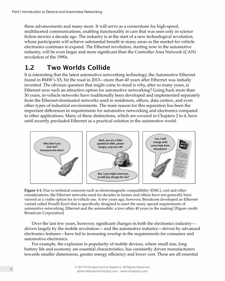
4
Part I: Introduction to General and Automotive Networking
© 2014 Intrepid Control Systems. All Rights Reserved. [email protected] • www.intrepidcs.com
these advancements and many more. It will serve as a cornerstone for high-speed, multifaceted communications, enabling functionality in cars that was seen only in science fiction movies a decade ago. The industry is at the start of a new technological revolution, whose participants will achieve substantial benefit in many areas as the market for vehicle electronics continues to expand. The Ethernet revolution, starting now in the automotive industry, will be even larger and more significant than the Controller Area Network (CAN) revolution of the 1990s.
1.2 Two Worlds CollideIt is interesting that the latest automotive networking technology, the Automotive Ethernet found in BMW’s X5, hit the road in 2013—more than 40 years after Ethernet was initially invented. The obvious question that might come to mind is why, after so many years, is Ethernet now such an attractive option for automotive networking? Going back more than 30 years, in-vehicle networks have traditionally been developed and implemented separately from the Ethernet-dominated networks used in residences, offices, data centers, and even other types of industrial environments. The main reason for this separation has been the important differences in requirements for automotive networking and electronics compared to other applications. Many of these distinctions, which are covered in Chapters 2 to 4, have until recently precluded Ethernet as a practical solution in the automotive world.
Well, you are a li,le spoiled on EMC, power hungry, and over 40!
Why don’t you love me?
Everyone else does!
But, I just might need you, so will you change for me?
Yes, I will change with
some help from Broadcom!
Figure 1-1: Due to technical concerns such as electromagnetic compatibility (EMC), cost and other considerations, the Ethernet networks used for decades in homes and offices have not generally been viewed as a viable option for in-vehicle use. A few years ago, however, Broadcom developed an Ethernet variant called BroadR-Reach that is specifically designed to meet the many special requirements of automotive networking. Ethernet and the automobile: a love affair 40 years in the making! [Figure credit: Broadcom Corporation]
Over the last few years, however, significant changes in both the electronics industry—driven largely by the mobile revolution— and the automotive industry—driven by advanced electronics features—have led to increasing overlap in the requirements for consumer and automotive electronics.
For example, the explosion in popularity of mobile devices, where small size, long battery life and economy are essential characteristics, has constantly driven manufacturers towards smaller dimensions, greater energy efficiency and lower cost. These are all essential
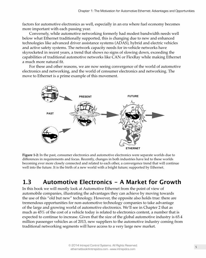
5
Chapter 1: The Motivation for Automotive Ethernet: Advantages and Opportunities
© 2014 Intrepid Control Systems. All Rights Reserved. [email protected] • www.intrepidcs.com
factors for automotive electronics as well, especially in an era where fuel economy becomes more important with each passing year.
Conversely, while automotive networking formerly had modest bandwidth needs well below what Ethernet traditionally supported, this is changing due to new and enhanced technologies like advanced driver assistance systems (ADAS), hybrid and electric vehicles and active safety systems. The network capacity needs for in-vehicle networks have skyrocketed in recent years, a trend that shows no signs of slowing down, exceeding the capabilities of traditional automotive networks like CAN or FlexRay while making Ethernet a much more natural fit.
For these and other reasons, we are now seeing convergence of the world of automotive electronics and networking, and the world of consumer electronics and networking. The move to Ethernet is a prime example of this movement.
PAST
PRESENT FUTURE
ETHERNET
Figure 1-2: In the past, consumer electronics and automotive electronics were separate worlds due to differences in requirements and focus. Recently, changes in both industries have led to these worlds becoming ever more closely connected and related to each other, a convergence trend that will continue well into the future. It is the birth of a new world with a bright future; supported by Ethernet.
1.3 Automotive Electronics - A Market for GrowthIn this book we will mostly look at Automotive Ethernet from the point of view of automobile companies, illustrating the advantages they can achieve by moving towards the use of this “old but new” technology. However, the opposite also holds true: there are tremendous opportunities for non-automotive technology companies to take advantage of the large and growing world of automotive electronics. We’ll see in Chapter 2 that as much as 45% of the cost of a vehicle today is related to electronics content, a number that is expected to continue to increase. Given that the size of the global automotive industry is 65.4 million passenger vehicles as of 2013, new suppliers to the automotive industry coming from traditional networking segments will have access to a very large new market.
6
Part I: Introduction to General and Automotive Networking
© 2014 Intrepid Control Systems. All Rights Reserved. [email protected] • www.intrepidcs.com
This is exactly what we see happening at Broadcom, for example, as illustrated by this quote from Broadcom’s Director of Wireless Connectivity, Richard Barrett:
“My role at Broadcom is focused on bringing our technical prowess and expertise in wireless connectivity to the automotive industry… Broadcom is paving the way for in-vehicle high-speed connectivity and content streaming. The automotive market represents a huge opportunity for semiconductor companies, as evidenced by a recent report from Strategy Analytics that estimates the market will reach $39 billion by 2020. Broadcom envisions the car as the next frontier and platform for intelligent connectivity, and is partnering with leading automakers and tier one suppliers to drive continued innovation in the automotive space.”
– Richard Barrett, Director of Wireless Connectivity at Broadcom
To offer an illustration of the relative sizes of the automotive and conventional networking markets, we decided to compare the number of Ethernet ports installed in conventional network products that ship each year to the number of CAN nodes installed in new vehicles—and some may find our results surprising. As of 2014, an estimated 400 million wired Ethernet ports ship worldwide each year, including all speeds and types. In contrast, the number of CAN nodes used in new cars annually can be conservatively estimated to be in the neighborhood of 1.2 billion—three times as many!
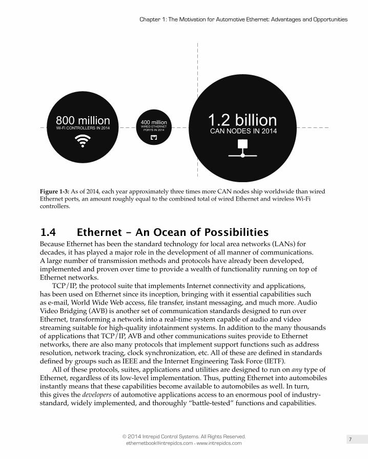
7
Chapter 1: The Motivation for Automotive Ethernet: Advantages and Opportunities
© 2014 Intrepid Control Systems. All Rights Reserved. [email protected] • www.intrepidcs.com
400 millionWIRED ETHERNET
PORTS IN 2014
1.2 billionCAN NODES IN 2014Wi-Fi CONTROLLERS IN 2014
800 million
Figure 1-3: As of 2014, each year approximately three times more CAN nodes ship worldwide than wired Ethernet ports, an amount roughly equal to the combined total of wired Ethernet and wireless Wi-Fi controllers.
1.4 Ethernet - An Ocean of PossibilitiesBecause Ethernet has been the standard technology for local area networks (LANs) for decades, it has played a major role in the development of all manner of communications. A large number of transmission methods and protocols have already been developed, implemented and proven over time to provide a wealth of functionality running on top of Ethernet networks.
TCP/IP, the protocol suite that implements Internet connectivity and applications, has been used on Ethernet since its inception, bringing with it essential capabilities such as e-mail, World Wide Web access, file transfer, instant messaging, and much more. Audio Video Bridging (AVB) is another set of communication standards designed to run over Ethernet, transforming a network into a real-time system capable of audio and video streaming suitable for high-quality infotainment systems. In addition to the many thousands of applications that TCP/IP, AVB and other communications suites provide to Ethernet networks, there are also many protocols that implement support functions such as address resolution, network tracing, clock synchronization, etc. All of these are defined in standards defined by groups such as IEEE and the Internet Engineering Task Force (IETF).
All of these protocols, suites, applications and utilities are designed to run on any type of Ethernet, regardless of its low-level implementation. Thus, putting Ethernet into automobiles instantly means that these capabilities become available to automobiles as well. In turn, this gives the developers of automotive applications access to an enormous pool of industry-standard, widely implemented, and thoroughly “battle-tested” functions and capabilities.
8
Part I: Introduction to General and Automotive Networking
© 2014 Intrepid Control Systems. All Rights Reserved. [email protected] • www.intrepidcs.com
Furthermore, not only does Ethernet offer a myriad of protocol and application options for vehicle companies, it also grants them access to a much larger pool of human capital, enabling synergies between conventional technology and automotive technology companies that were not possible before. No longer will communication among electronic control units (ECUs) in a vehicle be based on technology unique to the industry; they will use the same technology found in nearly every other industry as well. This will, in turn, make cooperation among industries easier, opening up the possibility of advanced features and uses that have so far been only speculated upon, and others that have yet to be dreamed up. We will soon have cars with advanced audio and video streaming functionality that has traditionally only been found in home or professional systems; automobiles talking to toll booths; intelligent charging systems; and even further advances in the area of autonomous vehicles. The integration trend between the automotive and non-automotive industries is being led by companies like Broadcom, a California-based semiconductor company that has traditionally derived most of its revenue from outside the automotive industry, but is now becoming a large player in this market.
1.5 Increasing Bandwidth and Future-Proof Technology
One of the challenges that has faced electronics engineers in the automotive world over the last 20 years is the lack of bandwidth provided by CAN, the dominant vehicle networking technology. When CAN was first developed by Bosch in the 1980s, its nominal speed of 1 Mb/s was more than adequate for the needs of the time. However, the automotive industry is not immune to the effects of Moore’s Law, which states that the transistor density—and therefore the computing power—of microprocessors doubles every two years. As the processing power in ECUs increases, the bandwidth needs for the network connecting these ECUs goes up accordingly. Over the last two decades, the ECUs in automobiles have become much more powerful than their early predecessors, while CAN has remained at its fixed limit of 1Mb/s, a level of capacity that is simply inadequate for most modern vehicles.
As we described at the start of the chapter, switching to a new networking technology is an enormously challenging task; one can see an example of the difficulties by considering the excitement and efforts that once surrounded FlexRay. Transitioning Ethernet into vehicles will also require a huge effort, but there is one essential difference: once Ethernet is in the vehicle, it offers the promise of being not only a technology proven in the past, but one that has proven its ability to adapt going into the future. One of the main reasons why Ethernet has been so successful over such a long period of time is its ability to evolve, change, and support ever increasing bandwidth requirements, while maintaining backward compatibility with legacy systems.
In Chapter 7 we will look at the OSI Reference Model in detail, which will explain the concept of protocol stacks and the tremendous advantages afforded by a layered approach to networking. Ethernet has been one of the prime beneficiaries of this modular approach to network design, allowing substantial changes to be made to low-level implementation details at the Physical Layer (layer 1 of the OSI model) in order to implement new cabling types and faster operating speeds, while leaving all of the higher-level protocols and software unchanged. This means protocol functionality provided by AVB, TCP/IP and other
9
Chapter 1: The Motivation for Automotive Ethernet: Advantages and Opportunities
© 2014 Intrepid Control Systems. All Rights Reserved. [email protected] • www.intrepidcs.com
technologies running over Ethernet remain the same even in the face of changes as dramatic as increasing the throughput of the network by a factor of 10. With Ethernet, no longer is it necessary to implement an entire new protocol stack if the low-level network changes, as would be the case with a transition from CAN to FlexRay, for example.
The first Ethernet invented in the early 1970s at Xerox’s Palo Alto Research Center bears little resemblance to the Ethernet you will find operating on a typical home or office LAN today—and even less to the high-speed Ethernet versions that are used in server rooms and data warehouses. Yet despite all the changes, they are all still Ethernet; the details have changed but the fundamentals remain largely the same. And so it is with the transition of Ethernet to the automotive world. Broadcom’s BroadR-Reach technology offers 100 Mb/s bandwidth over a single unshielded twisted pair wire. This is a method of transmission not used by any previous type of Ethernet, yet it integrates seamlessly with Ethernet at higher levels and works the same way.
BroadR-Reach is already in production cars, and as of 2014 is going through the IEEE 802 standardization process under the One Twisted Pair 100 Mb/s Ethernet (1TPCE) task group. At the same time, a much faster variant of the same technology is in development, called Reduced Twisted Pair Gigabit Ethernet (RTPGE). This technology promises to bring Automotive Ethernet speeds up to 1 Gb/s for the needs of future applications, while again maintaining full software compatibility. Mobile wireless technologies for vehicle to vehicle and vehicle to infrastructure “connected car” applications are also in the works, and again, these all support the full range of established protocols that enable voice over IP, video/audio communications, real-time data streaming and a host of other functions that will be essential for the cars of the future.
Key Information: One of the reasons Ethernet has been so successful over its 40-year lifespan is its ability to change, evolve and
support ever-increasing bandwidth while maintaining backward compatibility with higher-level protocols and software. An essential advantage that Ethernet technology offers to automotive companies is the ability to leverage this base of functionality while also enabling forward compatibility to permit greater performance in the future.
With Automotive Ethernet speeds poised to reach 1 Gb/s in the next few years, cars of the future will have a platform upon which features can be built that would be impossible with current networks. Examples include:
• Lower-cost and better-integrated radar and video systems to warn the driver of a lane departure or a possible forward collision.
• Faster and improved stability control systems that prevent a vehicle from losing traction during adverse weather conditions.
• Video systems that monitor the driver and provide a warning if the system detects that he or she is beginning to fall asleep.
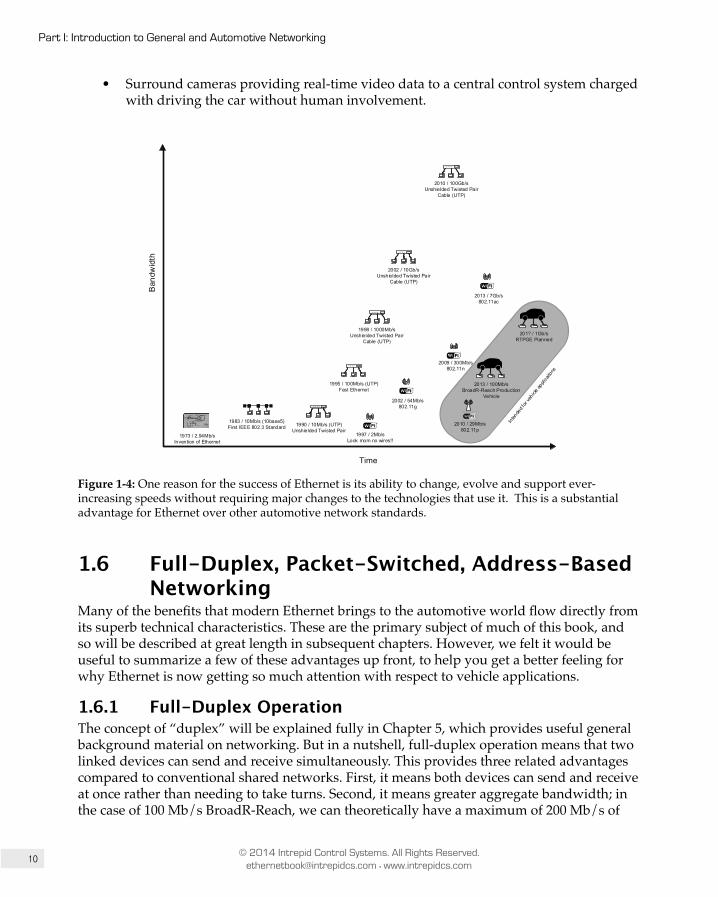
10
Part I: Introduction to General and Automotive Networking
© 2014 Intrepid Control Systems. All Rights Reserved. [email protected] • www.intrepidcs.com
• Surround cameras providing real-time video data to a central control system charged with driving the car without human involvement.
1973 / 2.94Mb/sInvention of Ethernet
Time
Ban
dwid
th
1983 / 10Mb/s (10base5)First IEEE 802.3 Standard 1990 / 10Mb/s (UTP)
Unshielded Twisted Pair
1995 / 100Mb/s (UTP)Fast Ethernet
1998 / 1000Mb/sUnshielded Twisted Pair
Cable (UTP)
2002 / 10Gb/sUnshielded Twisted Pair
Cable (UTP)
2010 / 100Gb/sUnshielded Twisted Pair
Cable (UTP)
2013 / 100Mb/sBroadR-Reach Production
Vehicle
1997 / 2Mb/sLook mom no wires!!
2009 / 300Mb/s802.11n
2002 / 54Mb/s802.11g
2013 / 7Gb/s802.11ac
201? / 1Gb/sRTPGE Planned
2010 / 29Mb/s802.11p
Figure 1-4: One reason for the success of Ethernet is its ability to change, evolve and support ever-increasing speeds without requiring major changes to the technologies that use it. This is a substantial advantage for Ethernet over other automotive network standards.
1.6 Full-Duplex, Packet-Switched, Address-Based Networking
Many of the benefits that modern Ethernet brings to the automotive world flow directly from its superb technical characteristics. These are the primary subject of much of this book, and so will be described at great length in subsequent chapters. However, we felt it would be useful to summarize a few of these advantages up front, to help you get a better feeling for why Ethernet is now getting so much attention with respect to vehicle applications.
1.6.1 Full-Duplex OperationThe concept of “duplex” will be explained fully in Chapter 5, which provides useful general background material on networking. But in a nutshell, full-duplex operation means that two linked devices can send and receive simultaneously. This provides three related advantages compared to conventional shared networks. First, it means both devices can send and receive at once rather than needing to take turns. Second, it means greater aggregate bandwidth; in the case of 100 Mb/s BroadR-Reach, we can theoretically have a maximum of 200 Mb/s of
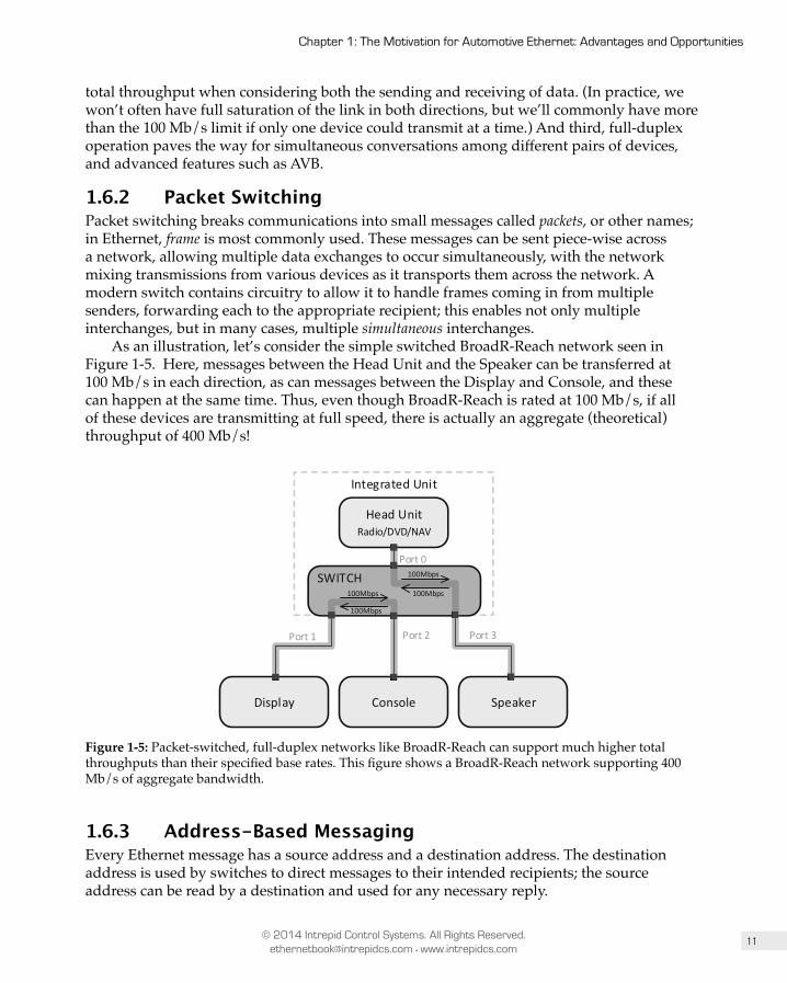
11
Chapter 1: The Motivation for Automotive Ethernet: Advantages and Opportunities
© 2014 Intrepid Control Systems. All Rights Reserved. [email protected] • www.intrepidcs.com
total throughput when considering both the sending and receiving of data. (In practice, we won’t often have full saturation of the link in both directions, but we’ll commonly have more than the 100 Mb/s limit if only one device could transmit at a time.) And third, full-duplex operation paves the way for simultaneous conversations among different pairs of devices, and advanced features such as AVB.
1.6.2 Packet SwitchingPacket switching breaks communications into small messages called packets, or other names; in Ethernet, frame is most commonly used. These messages can be sent piece-wise across a network, allowing multiple data exchanges to occur simultaneously, with the network mixing transmissions from various devices as it transports them across the network. A modern switch contains circuitry to allow it to handle frames coming in from multiple senders, forwarding each to the appropriate recipient; this enables not only multiple interchanges, but in many cases, multiple simultaneous interchanges.
As an illustration, let’s consider the simple switched BroadR-Reach network seen in Figure 1-5. Here, messages between the Head Unit and the Speaker can be transferred at 100 Mb/s in each direction, as can messages between the Display and Console, and these can happen at the same time. Thus, even though BroadR-Reach is rated at 100 Mb/s, if all of these devices are transmitting at full speed, there is actually an aggregate (theoretical) throughput of 400 Mb/s!
Head UnitRadio/DVD/NAV
Display Console Speaker
Integrated Unit
Port 0
Port 1 Port 2 Port 3
SWITCH100Mbps
100Mbps
100Mbps
100Mbps
Figure 1-5: Packet-switched, full-duplex networks like BroadR-Reach can support much higher total throughputs than their specified base rates. This figure shows a BroadR-Reach network supporting 400 Mb/s of aggregate bandwidth.
1.6.3 Address-Based MessagingEvery Ethernet message has a source address and a destination address. The destination address is used by switches to direct messages to their intended recipients; the source address can be read by a destination and used for any necessary reply.
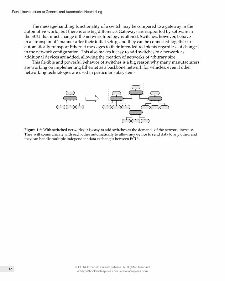
12
Part I: Introduction to General and Automotive Networking
© 2014 Intrepid Control Systems. All Rights Reserved. [email protected] • www.intrepidcs.com
The message-handling functionality of a switch may be compared to a gateway in the automotive world, but there is one big difference. Gateways are supported by software in the ECU that must change if the network topology is altered. Switches, however, behave in a “transparent” manner after their initial setup, and they can be connected together to automatically transport Ethernet messages to their intended recipients regardless of changes in the network configuration. This also makes it easy to add switches to a network as additional devices are added, allowing the creation of networks of arbitrary size.
This flexible and powerful behavior of switches is a big reason why many manufacturers are working on implementing Ethernet as a backbone network for vehicles, even if other networking technologies are used in particular subsystems.
Figure 1-6: With switched networks, it is easy to add switches as the demands of the network increase. They will communicate with each other automatically to allow any device to send data to any other, and they can handle multiple independent data exchanges between ECUs.

13
Chapter 1: The Motivation for Automotive Ethernet: Advantages and Opportunities
© 2014 Intrepid Control Systems. All Rights Reserved. [email protected] • www.intrepidcs.com
Figure 1-7: The inherent characteristics of Ethernet make it a good candidate for an in-vehicle backbone network bridging multiple domains.
1.7 Electrical IsolationAn essential feature of Ethernet networks is the electrical isolation requirements of their physical layer implementations, which are described in the IEEE 802.3 standard, and based on specifications laid out in the standard IEC 60950-1:2001, Information Technology Equipment - Safety. These isolation requirements vary by the specific Ethernet speed and cabling interface, but for newer types such as Gigabit Ethernet, require that the interface between the Ethernet controller and cable be required to pass at least one of these three electrical tests:
1. 1500 Vrms at 50 Hz to 60 Hz for 60 seconds.2. 2250 Vdc for 60 seconds.3. A sequence of ten 2400 V impulses of alternating polarity, applied at intervals of not
less than 1 second.
These constraints give Ethernet implementations significant resilience in harsh electrical environments, and are one reason why Ethernet has become very popular for long-distance, high-speed transmission, as well as factory automation. Broadcom’s BroadR-Reach technology has its own isolation requirements, which are governed by the Automotive Electronics Council’s AEC-Q100 specification.
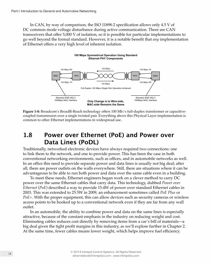
14
Part I: Introduction to General and Automotive Networking
© 2014 Intrepid Control Systems. All Rights Reserved. [email protected] • www.intrepidcs.com
In CAN, by way of comparison, the ISO 11898-2 specification allows only 4.5 V of DC common mode voltage disturbance during active communication. There are CAN transceivers that offer 5,000 V of isolation, so it is possible for particular implementations to go well beyond the formal standard. However, it is a notable benefit that any implementation of Ethernet offers a very high level of inherent isolation.
100 Mbps Symmetrical Operation Using StandardEthernet PHY Components
100 Mbps RX
100 Mbps TX
PHY
Standard IEEE 802.3100Mbps MAC Interface
100 Mbps
Full Duplex 100 Mbps Single-Pair Operation Achieved
Only Change is to Wire-side,MAC-side Remains the Same
Standard IEEE 802.3100Mbps MAC Interface
100 Mbps TX
100 Mbps RX
MACPHYMAC
100 Mbps
Figure 1-8: Broadcom’s BroadR-Reach technology offers 100 Mb/s full-duplex transformer or capacitive-coupled transmission over a single twisted pair. Everything above this Physical Layer implementation is common to other Ethernet implementations in widespread use.
1.8 Power over Ethernet (PoE) and Power over Data Lines (PoDL)
Traditionally, networked electronic devices have always required two connections: one to link them to the network, and one to provide power. This has been the case in both conventional networking environments, such as offices, and in automobile networks as well. In an office this need to provide separate power and data lines is usually not big deal; after all, there are power outlets on the walls everywhere. Still, there are situations where it can be advantageous to be able to run both power and data over the same cable even in a building.
To meet these needs, Ethernet engineers began work on a clever method to carry DC power over the same Ethernet cables that carry data. This technology, dubbed Power over Ethernet (PoE) described a way to provide 15.4W of power over standard Ethernet cables in 2003. This was extended to 25.5W in 2009, an enhancement sometimes called PoE Plus or PoE+. With the proper equipment, this can allow devices such as security cameras or wireless access points to be hooked up to a conventional network even if they are far from any wall outlet.
In an automobile, the ability to combine power and data on the same lines is especially attractive, because of the constant emphasis in the industry on reducing weight and cost. Eliminating cables reduces cost directly by removing items from a car’s bill of materials—a big deal given the tight profit margins in this industry, as we’ll explore further in Chapter 2. At the same time, fewer cables means lower weight, which helps improve fuel efficiency.
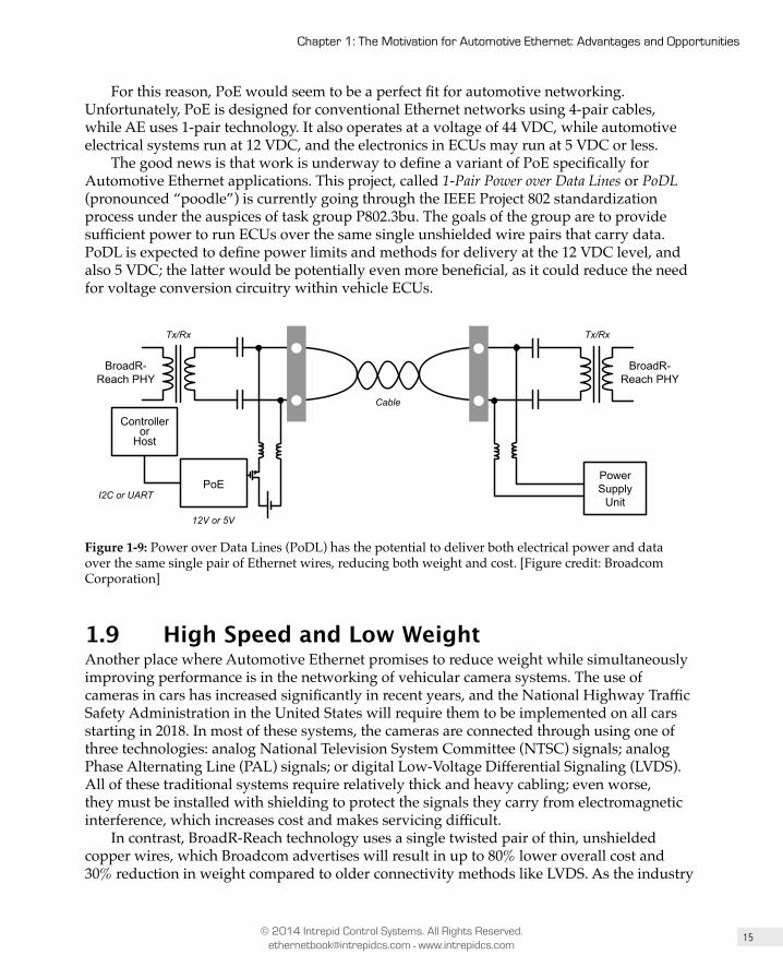
15
Chapter 1: The Motivation for Automotive Ethernet: Advantages and Opportunities
© 2014 Intrepid Control Systems. All Rights Reserved. [email protected] • www.intrepidcs.com
For this reason, PoE would seem to be a perfect fit for automotive networking. Unfortunately, PoE is designed for conventional Ethernet networks using 4-pair cables, while AE uses 1-pair technology. It also operates at a voltage of 44 VDC, while automotive electrical systems run at 12 VDC, and the electronics in ECUs may run at 5 VDC or less.
The good news is that work is underway to define a variant of PoE specifically for Automotive Ethernet applications. This project, called 1-Pair Power over Data Lines or PoDL (pronounced “poodle”) is currently going through the IEEE Project 802 standardization process under the auspices of task group P802.3bu. The goals of the group are to provide sufficient power to run ECUs over the same single unshielded wire pairs that carry data. PoDL is expected to define power limits and methods for delivery at the 12 VDC level, and also 5 VDC; the latter would be potentially even more beneficial, as it could reduce the need for voltage conversion circuitry within vehicle ECUs.
Tx/Rx
BroadR-Reach PHY
Controlleror
Host
PoE
Cable
I2C or UART
12V or 5V
PowerSupply
Unit
Tx/Rx
BroadR-Reach PHY
Figure 1-9: Power over Data Lines (PoDL) has the potential to deliver both electrical power and data over the same single pair of Ethernet wires, reducing both weight and cost. [Figure credit: Broadcom Corporation]
1.9 High Speed and Low WeightAnother place where Automotive Ethernet promises to reduce weight while simultaneously improving performance is in the networking of vehicular camera systems. The use of cameras in cars has increased significantly in recent years, and the National Highway Traffic Safety Administration in the United States will require them to be implemented on all cars starting in 2018. In most of these systems, the cameras are connected through using one of three technologies: analog National Television System Committee (NTSC) signals; analog Phase Alternating Line (PAL) signals; or digital Low-Voltage Differential Signaling (LVDS). All of these traditional systems require relatively thick and heavy cabling; even worse, they must be installed with shielding to protect the signals they carry from electromagnetic interference, which increases cost and makes servicing difficult.
In contrast, BroadR-Reach technology uses a single twisted pair of thin, unshielded copper wires, which Broadcom advertises will result in up to 80% lower overall cost and 30% reduction in weight compared to older connectivity methods like LVDS. As the industry
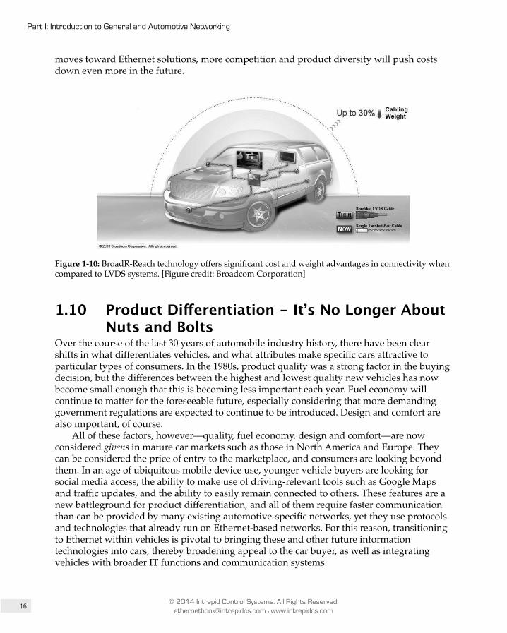
16
Part I: Introduction to General and Automotive Networking
© 2014 Intrepid Control Systems. All Rights Reserved. [email protected] • www.intrepidcs.com
moves toward Ethernet solutions, more competition and product diversity will push costs down even more in the future.
Figure 1-10: BroadR-Reach technology offers significant cost and weight advantages in connectivity when compared to LVDS systems. [Figure credit: Broadcom Corporation]
1.10 Product Differentiation - It’s No Longer About Nuts and Bolts
Over the course of the last 30 years of automobile industry history, there have been clear shifts in what differentiates vehicles, and what attributes make specific cars attractive to particular types of consumers. In the 1980s, product quality was a strong factor in the buying decision, but the differences between the highest and lowest quality new vehicles has now become small enough that this is becoming less important each year. Fuel economy will continue to matter for the foreseeable future, especially considering that more demanding government regulations are expected to continue to be introduced. Design and comfort are also important, of course.
All of these factors, however—quality, fuel economy, design and comfort—are now considered givens in mature car markets such as those in North America and Europe. They can be considered the price of entry to the marketplace, and consumers are looking beyond them. In an age of ubiquitous mobile device use, younger vehicle buyers are looking for social media access, the ability to make use of driving-relevant tools such as Google Maps and traffic updates, and the ability to easily remain connected to others. These features are a new battleground for product differentiation, and all of them require faster communication than can be provided by many existing automotive-specific networks, yet they use protocols and technologies that already run on Ethernet-based networks. For this reason, transitioning to Ethernet within vehicles is pivotal to bringing these and other future information technologies into cars, thereby broadening appeal to the car buyer, as well as integrating vehicles with broader IT functions and communication systems.

17
Chapter 1: The Motivation for Automotive Ethernet: Advantages and Opportunities
© 2014 Intrepid Control Systems. All Rights Reserved. [email protected] • www.intrepidcs.com
1.11 Wireless FunctionalityOne of the best examples of how Ethernet has been able to adapt to new requirements and possibilities over the years was the introduction of the now very popular wireless networking technology known as Wi-Fi. Wi-Fi is not exactly the same as Ethernet—the two have different underlying technical details, and Wi-Fi is defined by the IEEE 802.11 family of standards as opposed to Ethernet’s 802.3. But Wi-Fi was designed as an adaptation of Ethernet, and for this reason is sometimes called wireless Ethernet. In fact, the Wi-Fi Alliance, the trade group that promotes 802.11 adoption and advancement, was originally called the Wireless Ethernet Compatibility Alliance (WECA).
The point we made earlier about the operation of higher-level technologies being independent of the specific Ethernet implementation mostly apply even between Ethernet and Wi-Fi. The TCP/IP protocol suite and the applications that power the Internet work in pretty much the same way whether your laptop is connected using an Ethernet controller and cable or a Wi-Fi controller talking to a hotspot. This means that putting Ethernet into automobiles opens the way for reliable and fast wireless communications as well, again without requiring a massive overhaul to higher-level software and applications.
Like Ethernet, Wi-Fi is constantly being enhanced and expanded to improve performance and to meet the changing needs of the networking world. And like Broadcom’s BroadR-Reach, there are Wi-Fi amendments specific to automotive uses—in this case a technology known as Wireless Access in Vehicular Environments (WAVE), which was defined in the IEEE 802.11p specification published in 2010, and later incorporated into the main IEEE 802.11-2012 standard. This enhancement opens up new possibilities for vehicle-to-vehicle (V2V) and vehicle-to-infrastructure systems (V2I), supporting Intelligent Transportation Systems (ITS) initiatives to improve roadways in areas such as safety, traffic control, emergency warning and accident avoidance.
Vehicle-to-vehicle communication allows for the dynamic wireless exchange of data between cars on the road. This includes sending and receiving status data about each vehicle’s speed, direction and location—information that will eventually change the way roads and highways work. Knowledge of its surroundings will give 360º awareness to a vehicle’s control system, enabling it to sense possible hazards, warn the driver of danger, and even take immediate corrective action. V2V communications have the potential to reduce side-swipe collisions that occur when one car is in another’s blind spot, or avoid fender-benders caused by a car braking more quickly than the driver in a following vehicle can react. The combination of passive warning and active steering and braking has the potential to dramatically increase road safety: according to the United States Department of Transportation Research, V2V technologies have the potential to prevent up to 76 percent of accidents on roadways. (Source: http://www.its.dot.gov/research/v2v.htm)
18
Part I: Introduction to General and Automotive Networking
© 2014 Intrepid Control Systems. All Rights Reserved. [email protected] • www.intrepidcs.com
Key Information: Ethernet is the most popular wired networking technology in the world, and was the basis for creating
Wi-Fi, the most popular wireless networking technology in the world. Bringing Ethernet into vehicles paves the way for Wi-Fi, which will in turn enable vehicle-to-vehicle (V2V) and vehicle-to-infrastructure (V2I) networking connectivity. Among the many potential benefits these can enable, V2V technologies have the potential to prevent over 3/4 of roadway accidents.
1.12 SummaryIn this chapter we have laid out the case for bringing Ethernet into vehicles despite the inherent challenges and costs in introducing a new technology to the automotive world. Automotive Ethernet is exciting because of the wide array of potential benefits it represents:
• Harmonizing automotive industry networks with the ones used by the rest of the world.
• Raising the bandwidth of in-vehicle networks.• Providing the means for future increases in bandwidth without the need to change
higher-level protocols and software.• Easier to reconfigure in-vehicle networks as requirements change. • The ability to exploit an enormous base of established hardware and software
products, and developers and suppliers who understand them.• Reductions in vehicle weight and cost.• The potential to eliminate power cables by running power and data over the same
lines.• More variety in available functionality, and more options for differentiating products.• A pathway to wireless connectivity that will in turn enable vehicle-to-vehicle (V2V)
and vehicle-to-infrastructure (V2I) applications.
Even with all of these advantages in its favor, the transition to Ethernet won’t be easy. In particular, it will take time to convince automotive companies that Ethernet can be used for subsystems that transmit real-time control system information. We are confident, however, that over time, Automotive Ethernet will prove to be well worth the investment it will require and we will all experience the birth of a new and exciting era in the world of automotive networking.

2Chapter
Overview, Background and Business Requirements of Automotive Networkingby Colt Correa
2.1 IntroductionIn this chapter we will take a high-level look at automotive networking, and discuss some of the business requirements behind their effective design and implementation. The material presented will give you insight into what companies must take into account when supplying electronics hardware and software to be used in vehicles.
If you work in the industry, you may already be knowledgeable about much of what we have written here, but those new to the automotive world will find it an essential introduction. It would be possible to write an entire book on just the business of automobile electronics, but that would be unfeasible; instead, what we have done is to provide a general overview of the most common and important issues, with appropriate references for further reading.
Intrepid Control Systems is a network tools provider for many of the largest automotive manufacturers, which has provided us the opportunity to learn about many manufacturers’ specifications for vehicle electronics in general, and networking requirements in particular. In many cases this information is proprietary, and thus could not be published in a book such as this, but there are numerous open specifications available that we will reference. In addition,

20
Part I: Introduction to General and Automotive Networking
© 2014 Intrepid Control Systems. All Rights Reserved. [email protected] • www.intrepidcs.com
there are aspects common to many of the individual companies’ requirements, which we will highlight where appropriate.
We’ll begin the chapter with a brief history of how networking evolved within the automobile, and talk about the importance of safety and the various issues related to it. We’ll then discuss the growing importance of electronics in vehicles, and illustrate the essential differences between the consumer electronics and automotive electronics industries. Finally, we’ll summarize essential business and cost drivers that influence automotive networking design and adoption.
2.2 A Brief History of Automotive Networking2.2.1 The First Serial CommunicationsInternal data communications networks are part of a vehicle’s control system. They should not be, but often are, confused with the communications functionality for On-Board Diagnostics (OBD) and emissions testing tools, which preceded them.
Diagnostic networks enable an electronic control unit (ECU) or a set of ECUs to communicate with a test or factory tool for numerous purposes. This includes downloading new software, reading Diagnostic Trouble Codes (DTCs), providing information related to an emissions test, data acquisition of control system parameters, and many other purposes that are not part of the main functionality of the control system. This field as a whole is generally referred to as diagnostics, and is a world of its own in terms of communications protocols and general operation.
One of the earliest diagnostic networks was Assembly Line Diagnostic Link (ALDL), introduced by General Motors in 1980 . This was a point-to-point communication network designed to enable the powertrain control unit to communicate with an assembly line tool at the factory. In Europe, which at the time was dominated in the electronics space by Bosch, K-Line was the standard for most European OEMs. By the mid-to-late 1980s, many automobile manufacturers had some form of ECU-to-test-tool communications.
An essential characteristic of these diagnostic networks is that, generally, the network is inactive unless an external tool is connected to the vehicle. This matters because much more stringent requirements exist for networks that are active during normal operation of the vehicle than those that are not. For example, 100 Mb/s Ethernet using standard 4-pair cabling does not meet the electromagnetic compatibility (EMC) requirements of an in-vehicle network, but has long been used for diagnostic links. In addition, important functionality like sleep and power modes are not necessary for diagnostic systems, but are an essential part of vehicle network functionality.
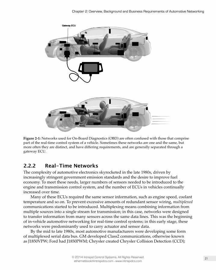
21
Chapter 2: Overview, Background and Business Requirements of Automotive Networking
© 2014 Intrepid Control Systems. All Rights Reserved. [email protected] • www.intrepidcs.com
Gateway ECU
Figure 2-1: Networks used for On-Board Diagnostics (OBD) are often confused with those that comprise part of the real-time control system of a vehicle. Sometimes these networks are one and the same, but more often they are distinct, and have differing requirements, and are generally separated through a gateway ECU.
2.2.2 Real-Time NetworksThe complexity of automotive electronics skyrocketed in the late 1980s, driven by increasingly stringent government emission standards and the desire to improve fuel economy. To meet these needs, larger numbers of sensors needed to be introduced to the engine and transmission control system, and the number of ECUs in vehicles continually increased over time.
Many of these ECUs required the same sensor information, such as engine speed, coolant temperature and so on. To prevent excessive amounts of redundant sensor wiring, multiplexed communications started to be introduced. Multiplexing means combining information from multiple sources into a single stream for transmission; in this case, networks were designed to transfer information from many sensors across the same data lines. This was the beginning of in-vehicle automotive networking for real-time control systems; in this early stage, these networks were predominantly used to carry actuator and sensor data.
By the mid to late 1980s, most automotive manufacturers were developing some form of multiplexed serial data bus. GM developed Class2 communications, otherwise known as J1850VPW; Ford had J1850PWM; Chrysler created Chrysler Collision Detection (CCD);
22
Part I: Introduction to General and Automotive Networking
© 2014 Intrepid Control Systems. All Rights Reserved. [email protected] • www.intrepidcs.com
PSA (Peugeot, Citroen) and Renault introduced the Vehicle Area Network (VAN); BMW developed I-Bus; and Toyota supported the Body Electronics Area Network (BEAN).
2.2.3 Establishing CAN as an Industry StandardIn Germany, Bosch developed a new bus as well, and documented it in a paper titled “Automotive Serial Controller Area Network” that was presented to the 1986 SAE congress in Detroit. At the time, most people had no idea how much of an impact that networking would eventually have on the industry. By the early 1990s, nearly every vehicle sold in the western world had some form of communication network, and Bosch’s bus—which came to be known simply as Controller Area Network or CAN—had become the first global industry standard for in-vehicle networking.
In 1990 Daimler-Benz (currently known just as Daimler) sold the first production vehicle equipped with Bosch’s CAN technology. Not long thereafter, driven by Bosch’s market clout, nearly every German OEM was using CAN in its vehicles, and this soon spread to OEMs across Europe. From there, the CAN wave traveled across the Atlantic to the USA, where Ford, Chrysler, and GM adopted it as a standard network for their own needs. CAN then made its way to Asia, with many Japanese manufacturers picking it up as well. By the mid 2000s, CAN held a dominant worldwide position in the automotive networking world.
It is important to understand what the widespread adoption of CAN represents. Not only was the technology itself successful, but its universal use represented a move away from proprietary, OEM-specific networking solutions, to an industry standard that everyone could agree upon. This in turn conferred upon all automakers the many benefits of using industry standards, including greater clarity of device requirements and capabilities, increased compatibility among OEMs, and more choice and lower cost in sourcing suppliers. Since then, nearly every new networking technology has been developed by a consortium of companies, with the goal being to drive toward a new standard that will achieve CAN’s level of widespread acceptance.
2.2.4 Beyond CANDespite’s CAN’s victory in the industry, it did not take long for it to become clear that its maximum throughput of 1 Mb/s and its non-deterministic message timing made the technology inadequate for some applications. In the late 1990s, the Media Oriented Serial Transport (MOST) Corporation was formed by BMW, Daimler-Benz and OASIS Silicon Systems (later acquired by SMSC, and now part of Microchip Technology) to create a new network better suited to multimedia applications. MOST has higher bandwidth, and offers built-in methods for streaming data and stream synchronization, areas where CAN is lacking; it was first introduced into production as part of the 2001 BMW 7 Series.
At around the same time that MOST was being developed to address areas where CAN didn’t provide enough speed and functionality, companies such as Volvo recognized that CAN was actually overkill for other applications, especially in the area of body and comfort systems. Adjusting power mirrors, opening and closing door locks, and other similarly simple operations do not require a network of even CAN’s capability. The desire for a lower-cost, simpler network led to the creation of the Local Interconnect Network (LIN) in 1998. Using a minimalistic single-wire topology and serial communications through industry standard universal asynchronous receiver/transmitters (UARTs), LIN is easy to support on
23
Chapter 2: Overview, Background and Business Requirements of Automotive Networking
© 2014 Intrepid Control Systems. All Rights Reserved. [email protected] • www.intrepidcs.com
any microcontroller, even the smallest and cheapest 8-bit models used in some of these low-speed applications. LIN grew in popularity throughout Europe and was standardized by the LIN Consortium; eventually it was also standardized under SAE J1602 in the United States.
At the turn of the century, BMW, DaimlerChrysler, Freescale, and Philips Semiconductors (now NXP) recognized the need for a more robust and higher speed network, with built in redundancy and strict real-time synchronization capability for safety-critical control applications. At that time, no other automotive network offered this capability, so they formed the FlexRay Consortium to design one. In 2006, the first vehicle equipped with FlexRay made it to production with the BMW X6, to much accompanying fanfare. With its 10 Mb/s transfer rate, dual redundant network topology and much improved synchronization capabilities, many in the industry thought that FlexRay was “the next big thing”—there were predictions that FlexRay would replace CAN as the main automotive network, and new tool companies were created to promote this new technology.
Despite its promise of more bandwidth and improved timing characteristics, however, FlexRay had a significant drawback. It was much more complicated and difficult to implement than CAN, which slowed its rate of adoption relative to expectations. Then, just as FlexRay was gaining some traction in the research and development phase at several large OEMs, the Great Recession hit. Detroit was affected more strongly than anywhere else, with GM and Chrysler both pushed into bankruptcy. Forced to deal with an existential crisis, networking technology changes were the last thing on these companies’ collective minds. This caused the spread of FlexRay to essentially stop dead in its tracks.
2.2.5 The Dawn of Automotive EthernetBy the time the Great Recession was over, BMW expressed interest in looking into Ethernet, with its promise of supporting much higher bandwidth than any other in-vehicle network that uses unshielded twisted pair cabling. Standard 100 Mb/s Ethernet could not meet automotive EMC requirements, and its 4-pair cabling was not an attractive option due to cost. However, years earlier, Broadcom had developed a single pair (2-wire) Ethernet Physical Layer called BroadR-Reach, which was designed for long distances, with a flexible data rate based on cable length. With BMW helping in the area of automotive EMC requirements, Broadcom adapted BroadR-Reach technology for in-vehicle use. The OPEN (“One Pair EtherNet”) Alliance was formed in 2011 by Broadcom, NXP, and Harman to promote an industry standard Ethernet specification based on BroadR-Reach for automotive applications. In 2013, BMW released its new X5, featuring the first Ethernet implementation as a real-time communication network for backup cameras.
Today, nearly every large OEM is part of the OPEN Alliance, and many of them have production plans to use this technology. In 2014, Bosch and other powerful members of the alliance pushed for BroadR-Reach to be standardized and included as part of the IEEE 802.3 Ethernet specification. This led to the formation of IEEE 802.3 One Twisted Pair 100 Mb/s Ethernet task force, abbreviated 1TPCE (using “C”, the Roman numeral for “100”). The standardization is now in progress under IEEE Project 802 designation P802.3bw.
It is our view that this technology is already too big to fail as the next major vehicle networking technology. Unfortunately for MOST, nearly every initial application of Automotive Ethernet focuses on infotainment systems, in many cases replacing that technology. Two of the founding members of the MOST Cooperation—Harman, the world’s

24
Part I: Introduction to General and Automotive Networking
© 2014 Intrepid Control Systems. All Rights Reserved. [email protected] • www.intrepidcs.com
largest infotainment system supplier, and BMW—are among the biggest proponents of Automotive Ethernet. Longer term, it might also be possible to replace FlexRay with Automotive Ethernet, as it offers the key advantage of at least 10 times the bandwidth.
1980 20201990 2000 2010
Early Vehicle NetworksOEM Specific
The CAN EraGlobal Standard Networks
2006 BMW X5First Production FlexRay
1990 Mercedes E-ClassFirst Production CAN
2013 BMW X5First Production Ethernet
FlexRay (thought to be next big thing)
2001 BMW 7 seriesFirst Production MOST
MOSTEthernet
LIN
2008 – 2012 Global CrisisLimits development on FlexRay and
other network technology
Figure 2-2: The progression of vehicle networks over time. Early OEM-specific networks were replaced by CAN, changing the industry’s approach from proprietary networks to global standards. Along with CAN, Ethernet will dominate vehicle networking for many years to come.
Key Information: One Twisted Pair 100 Mb/s Ethernet (1TPCE), based on Broadcom’s BroadR-Reach Physical Layer, is
already too big to fail. Many large automotive manufacturers have production plans for Automotive Ethernet as a base communications system for infotainment applications, in many cases replacing MOST. Longer term, Ethernet is also being developed as a backbone communications system for the entire vehicle, including safety-critical applications.
2.3 SafetyOne major difference between consumer electronics and automotive electronics is that many of the systems in a vehicle control safety-critical functionality. A failure or design defect in an automotive system can easily lead to human harm, whereas that is rarely the case with a laptop or smart phone. The safety considerations involved in automotive networking and electronics mean that suppliers and manufacturers in this industry have very different software and hardware requirements than their consumer electronics counterparts.

25
Chapter 2: Overview, Background and Business Requirements of Automotive Networking
© 2014 Intrepid Control Systems. All Rights Reserved. [email protected] • www.intrepidcs.com
Adaptive Cruise Control
AdaptiveHeadlights
Airbags
Anti-Lock Brake Systems (ABS)
Automated CollisionNotification
Automated Parking
Backup Sensorsand Cameras
Electronic Stability Control (ECS)
Lane DepartureWarning Systems
Night Vision
Seat Belts
Tire Pressure Monitoring
Traction Control Systems (TCS)
Figure 2-3: Numerous active and passive electronic safety features in modern vehicles help to make our roadways safer. Special care must be taken when designing these features, however, because unlike most consumer electronics, a failure here can lead to human harm.
2.3.1 The Double Edged Sword of Automotive Electronics Automotive electronics is a double-edged sword when it comes to safety.
Automotive Electronics Improve SafetyOn the one side, electronics help make possible advanced technologies that improve safety in ways such as these:
• Keeping us from wandering into the wrong lane on the highway.• Preventing a vehicle from sliding out of control on icy roads.• Warning us of a possible impending collision.• Helping us see behind the vehicle when backing up, to avoid driving over obstacles
or harming people or animals.• Turning headlights on when necessary to improve visibility.• Deploying airbags to prevent injury as an accident occurs.• Warning us when our tire pressure is getting low.
These and other features are now routinely deployed in automobiles, along with many others that drivers may not even be aware of, yet take for granted every day. These advances, combined with highway improvements over the years, have driven down accident rates in the last decade, making our roads continually safer.

26
Part I: Introduction to General and Automotive Networking
© 2014 Intrepid Control Systems. All Rights Reserved. [email protected] • www.intrepidcs.com
1.69
1.59
1.49 1.49 1.51 1.52 1.50 1.45
1.36 1.33 1.31 1.27 1.27
1.22 1.18
1.14 1.11 1.07
0.96
0.87 0.83
0.88 0.89
0.00
0.20
0.40
0.60
0.80
1.00
1.20
1.40
1.60
1.80
1990 1995 2000 2005 2010 2012
Fata
litie
s pe
r 100
Mill
ion
Veh
icle
Mile
s Tr
avel
ed
Figure 2-4: Over the years, the increase in automotive electronics has led to the implementation of numerous safety features that contribute to safer vehicles and roadways. [Source: National Highway Traffic Safety Administration.]
Automotive Electronics Detract from Safety and Lead to Consumer ConcernsOn the other edge of the sword we find issues where electronics actually detract from driver safety. One obvious issue is that sophisticated in-vehicle navigation and infotainment systems compete for the driver’s attention, leading to concerns over what is now called distracted driving. Much worse for the industry than this, however—which can be attributed to the driver’s decisions—is the notion that advanced electronic features offered by new vehicles give the driver less control, and the vehicle more control, meaning that a simple software bug could potentially lead to the deaths of not just the passengers in the affected vehicle, but many others nearby as well.
Unfortunately for those of us in the automotive electronics industry, as soon as we provide an electronic feature that influences a safety-critical system traditionally controlled exclusively by the driver and mechanical systems, this stokes consumer fears—as well as the aspirations of attorneys. For this reason, any automobile manufacturer or supplier to the industry must be careful to deliver exceedingly safe electronic solutions whenever they replace a traditional mechanical one. This is especially true because, unlike the mechanical systems they replace, failures of safety-critical software and electronics systems do not leave physical evidence of their occurrence. All of this creates a need for process, development, and testing requirements that are of little or no concern to the typical consumer electronics manufacturer.
These issues are just as important for in-vehicle networking systems as they are for other areas of automotive electronics. The higher data rates offered by Automotive Ethernet will increase the amount of electronics content in vehicles for decades to come, making safety and customer reassurance ever more essential.
27
Chapter 2: Overview, Background and Business Requirements of Automotive Networking
© 2014 Intrepid Control Systems. All Rights Reserved. [email protected] • www.intrepidcs.com
Figure 2-5: Automotive electronics is a double-edged sword when it comes to safety. On one edge we have beneficial features such as active and passive collision avoidance, backup cameras, warning systems and other features that have contributed to a steady increase in road safety. On the dangerous edge of the sword are the potential for electronic distractions and consumer fear due to a lack of general understanding of advanced electronics.
Key Information: Safety-critical electronic systems are much less well understood by the general public than the mechanical
systems they replace. In addition, failures in these systems often do not leave behind physical evidence of their occurrence. These and other factors lead to a psychological fear or mistrust of these advances by some in the general public, and the potential for litigation if something goes wrong. For this reason, it is necessary that these new systems be not merely as safe as the mechanical ones they replace, but appreciably more safe. Companies that use these features must also have documented processes and data that prove the functional safety of the systems in question.

28
Part I: Introduction to General and Automotive Networking
© 2014 Intrepid Control Systems. All Rights Reserved. [email protected] • www.intrepidcs.com
2.3.2 ISO 26262 - Road Vehicle Safety Standard for Electrical and Electronic Systems
Safety has always been a critical concern for automotive engineers, and so the concept of designing and testing for safety is not new. What has changed, though, as we discussed above, is the increased electronic content responsible for safety-critical functionality in vehicles. In recognition of this trend, the ISO 26262 standard was created; this specification is a derivative of IEC 61508, the standard used in the nuclear power generation industry, among others.
Unlike many of the specifications that we cover in this book, ISO 26262 does not directly describe specific technologies or test procedures. Rather, it focuses on the management, development and production processes required to ensure safety in the resulting product. The entire specification comprises a mammoth 10 volumes, encompassing the entire product development and production cycle from initial concept, through development and production, to maintenance, repair and decommissioning. It associates these processes with ways to reduce the risk of harm to humans to an acceptable level, depending on the severity of the possible failure of each system.
2.3.3 Automotive Safety Integrity Level (ASIL)ISO 26262 defines a system called the Automotive Safety Integrity Level (ASIL), which classifies the level of risk of human harm associated with a possible system failure. ASIL is based on three main components: the severity of a system failure in terms of harm to humans; the likelihood of an injury occurring due to a failure; and the ability of those involved in a failure to take action to avoid injury. Based on these factors, each system is assigned an ASIL letter classification—A, B, C, or D—with D being the most severe or safety-critical. It is also possible that a system may have no ASIL designation, if it is determined that a failure will not cause harm, or if a failure is incredibly unlikely. The “D” classification essentially means that there is reasonable likelihood that a failure will cause a car to become uncontrollable, and result in a potentially life-threatening injury.
CONTROLLABILITYSEVERITY LIKELIHOOD ASIL+ + =
Figure 2-6: The ASIL classification system provides a measure of how much attention should be placed on a system to reduce the risk of failure to an acceptable level. ASIL is focused only on injury and death of the driver, occupants and pedestrians, not on the consequences to the system itself.
To take an example to illustrate proper ASIL classification, consider an electronic braking system. Failure of such a system could lead to a car having no braking capability; this would mean that the driver, occupants and nearby pedestrians would have little ability to avoid harm. Therefore, this type of system would likely get a D classification. In contrast, an electronic seat position control system would get the lowest classification—an inability to move a seat would normally pose no threat to human harm. Furthermore, a failure here would likely be noticed when the driver first gets into the car, and therefore when the vehicle
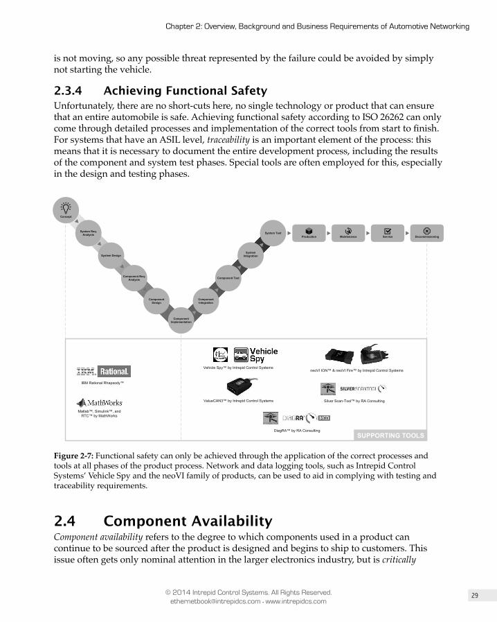
29
Chapter 2: Overview, Background and Business Requirements of Automotive Networking
© 2014 Intrepid Control Systems. All Rights Reserved. [email protected] • www.intrepidcs.com
is not moving, so any possible threat represented by the failure could be avoided by simply not starting the vehicle.
2.3.4 Achieving Functional SafetyUnfortunately, there are no short-cuts here, no single technology or product that can ensure that an entire automobile is safe. Achieving functional safety according to ISO 26262 can only come through detailed processes and implementation of the correct tools from start to finish. For systems that have an ASIL level, traceability is an important element of the process: this means that it is necessary to document the entire development process, including the results of the component and system test phases. Special tools are often employed for this, especially in the design and testing phases.
Component Design
Component Req. Analysis
System Design
Component Implementation
Component Integration
System Test
Component Test
System Integration
Concept
System Req. Analysis
Production Maintenance Service Decommissioning
neoVI ION™ & neoVI Fire™ by Intrepid Control Systems
IBM Rational Rhapsody™
Matlab™, Simulink™, and RTC™ by MathWorks
Silver Scan-Tool™ by RA Consulting
SUPPORTING TOOLSDiagRA™ by RA Consulting
Vehicle Spy™ by Intrepid Control Systems
ValueCAN3™ by Intrepid Control Systems
Figure 2-7: Functional safety can only be achieved through the application of the correct processes and tools at all phases of the product process. Network and data logging tools, such as Intrepid Control Systems’ Vehicle Spy and the neoVI family of products, can be used to aid in complying with testing and traceability requirements.
2.4 Component AvailabilityComponent availability refers to the degree to which components used in a product can continue to be sourced after the product is designed and begins to ship to customers. This issue often gets only nominal attention in the larger electronics industry, but is critically

30
Part I: Introduction to General and Automotive Networking
© 2014 Intrepid Control Systems. All Rights Reserved. [email protected] • www.intrepidcs.com
important in the automotive world. There are two main reasons for this: the need to service vehicles already on the road, and the desire to reuse proven components in subsequent revisions of an automobile design. In this section we will explain the reasons why automotive and consumer electronics differ so dramatically with respect to availability concerns.
2.4.1 Contrasting the Average Lifespan of Consumer Electronics and Vehicles
Most people who purchase a new tablet or mobile phone expect to use it for a relatively short time: generally until it is broken or lost, or a new version comes out with enough new power or features to justify an upgrade. The timeframe from initial purchase to replacement in the consumer electronics market is typically rather short: often only a few years, and in some cases only a single year. Even those who want to keep their devices for longer timeframes eventually encounter problems or failures and are faced with a harsh reality of the technology world: it is often nearly as expensive to repair a device as to simply buy a new one.
This situation stands in stark contrast to the automotive world. Few people buy a new car expecting to replace it after a year or two; the expectation is that the vehicle will be usable to its full potential for at least 15 years. (In fact, the average age of vehicles on the road in the United States in 2013 was just over 11 years.) During the course of this decade or more, any component in a car may fail, and its owner must be able to take it to a service center to have it replaced. Therefore, auto companies must ensure that every component—including every electronic component—is available for a long time; 10 to 15 years is used as a general rule of thumb by most automotive companies.
This distinction represents a very different set of requirements for those who make networking products for consumer goods and those who supply the automotive industry. If you are an electronics component manufacturer that desires to obtain an automobile company as a customer, you will likely be required to prove that your part will be available for at least a full decade.

31
Chapter 2: Overview, Background and Business Requirements of Automotive Networking
© 2014 Intrepid Control Systems. All Rights Reserved. [email protected] • www.intrepidcs.com
Figure 2-8: Electronic components in a vehicle are expected to last an order of magnitude longer than those of devices like tablet computers.
Key Information: In the consumer electronics world, devices are often kept for only a couple of years, and disposed of when an
important component fails. But customers purchase vehicles expecting them to be usable at full functionality for at least 15 years. While the average lifespan of a tablet computer is just under 2 years, the average age of a vehicle on the road in the US is just over 11 years. Even if a failure occurs in a car 15 years after purchase, it is expected that there will be a replacement part available, even for non-critical components in areas such as its navigation or audio system.
2.4.2 The Development Cycle of Consumer Electronics Compared to Automobiles
A major reason for the short life-spans of consumer electronics devices is that their manufacturers deliberately work on very short product development cycles in order to encourage frequent upgrades. Seemingly every month a swath of new models of smart phones, tablets, laptops and other gadgets hits the market, promising new features, faster operation, or other enticements. This is in turn driven by the makers of microprocessors, solid state drives, memory chips and other subcomponents, which provide reasons for new products to be created that will appeal to buyers. Most new consumer electronics devices are heavily redesigned to add these new capabilities, improve battery life, reduce size and
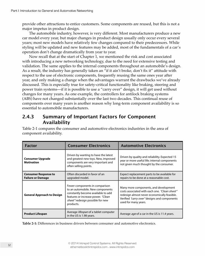
32
Part I: Introduction to General and Automotive Networking
© 2014 Intrepid Control Systems. All Rights Reserved. [email protected] • www.intrepidcs.com
provide other attractions to entice customers. Some components are reused, but this is not a major impetus in product design.
The automobile industry, however, is very different. Most manufacturers produce a new car model every year, but major changes in product design usually only occur every several years; most new models have relatively few changes compared to their predecessors. While styling will be updated and new features may be added, most of the fundamentals of a car’s operation don’t change dramatically from year to year.
Now recall that at the start of Chapter 1, we mentioned the risk and cost associated with introducing a new networking technology, due to the need for extensive testing and validation. The same applies to the internal components throughout an automobile’s design. As a result, the industry has generally taken an “if it ain’t broke, don’t fix it” attitude with respect to the use of electronic components, frequently reusing the same ones year after year, and only making a change when the advantages warrant the drawbacks we’ve already discussed. This is especially true for safety-critical functionality like braking, steering and power train systems—if it is possible to use a “carry over” design, it will get used without changes for many years. As one example, the controllers for antilock braking systems (ABS) have not changed substantially over the last two decades. This continual reuse of components over many years is another reason why long-term component availability is so essential to automobile manufacturers.
2.4.3 Summary of Important Factors for Component Availability
Table 2-1 compares the consumer and automotive electronics industries in the area of component availability.
Factor Consumer Electronics Automotive Electronics
Consumer Upgrade Motivation
Driven by wanting to have the latest and greatest new toys. New, improved components are very important and often selling points.
Driven by quality and reliability. Expected 15 year or more useful life; internal components not given much thought by the consumer.
Consumer Response to Failure or Damage
Often discarded in favor of an upgraded model.
Expect replacement parts to be available for repairs to be done at a reasonable cost.
General Approach to Design
Fewer components in comparison to an automobile. New components constantly become available to add features or increase power. “Clean sheet” redesign possible for new products.
Many more components, and development costs associated with each one. “Clean sheet” redesign almost never economically feasible. Verified “carry over” designs and components used for many years.
Product Lifespan Average lifespan of a tablet computer in the US is 1.98 years. Average age of a car in the US is 11.4 years.
Table 2-1: Differences in business drivers between consumer and automotive electronics.
33
Chapter 2: Overview, Background and Business Requirements of Automotive Networking
© 2014 Intrepid Control Systems. All Rights Reserved. [email protected] • www.intrepidcs.com
2.5 Cost ConsiderationsIn the early 1990s, Intel owned the market for silicon that supported CAN—the most widespread automotive network technology of the time—but by the late 1990s, had given up its leadership position. Many silicon companies invested in the development of microcontrollers with integrated CAN support built in, and NXP became the leader for transceivers implementing the technology.
At the time, many in the automotive industry did not understand why a company like Intel would essentially walk away from a market it had the ability to dominate. Looking back, though, is easy to see why this happened.
The “dot com” boom of the late 1990s was a time when any company associated with technology needed dump trucks to haul away the cash that was being thrown at them by investors. Back then—as is still mainly the case today—these investors considered the automotive industry to be part of the “old economy”. Association with the car industry was not the best thing for a company’s stock price, and certainly not an area where technology companies saw themselves in the future. Furthermore, as we will show, competitive price pressure in the automotive industry is quite strong; as new semiconductor manufacturers entered the market to make automotive CAN chips, it became not worth Intel’s time and money to invest further in this segment. They could instead spend their valuable R&D dollars on new processors, which they could sell at much higher profit margins.
Naturally, the costs associated with development, manufacturing, and support are important in all industries, but they are especially consequential in the auto industry. As we’ll see, profit margins are so small here that that there is constant and strong pressure to reduce the cost of everything in a vehicle—including electronic components.
2.5.1 Electronics Content in a Modern VehicleIf you drive down to a local premium vehicle dealer and take their latest model out for a test drive, you will be operating a machine with more than 100 microprocessors, all networked together, running up to 100 million lines of code. The cost of all of this hardware and software now represents as much as 45% of the overall cost of a premium vehicle; even on more conventional automobiles it is in the neighborhood of 30%. New electronic functionality will continue to be added every year for the foreseeable future, which means that these numbers will only increase. By 2030, it is projected that 50% of the cost of all vehicles will be due to electronics alone.
Figure 2-9 shows the industry average for the cost of electronics in a vehicle as a percentage of overall manufacturing cost. As it stands today, a vehicle’s cost is already based more on silicon than steel! The takeaway point here is that the overall cost of a car is largely electronics-related and that this trend will continue. Therefore, any new technology, such as Automotive Ethernet, needs to be cost-effective—not only should it not add cost relative to existing options, it should hopefully allow costs to be reduced.

34
Part I: Introduction to General and Automotive Networking
© 2014 Intrepid Control Systems. All Rights Reserved. [email protected] • www.intrepidcs.com
1% 3% 4%
10%
15%
20%
30%
35%
50%
0%
10%
20%
30%
40%
50%
60%
1950 1960 1970 1980 1990 2000 2010 2020 2030
Sha
re o
f tot
al c
ost
Figure 2-9: The amount of electronics content, as a percentage of the overall vehicle cost, is already substantial, and this will only continue to increase in the future. [Source: statista.com]
Key Information: The overall cost of a car is largely electronics-related, a trend that will continue for years to come. Automotive
Ethernet is attractive in part because it adds capability not only without adding cost compared to traditional networks, but potentially by reducing it.
2.5.2 Profit Margins for Automotive ManufacturersCompared to large technology companies like Google or Apple, the profit margins for large multinational automotive manufacturers is miniscule. There are numerous reasons for this, including broad competition, limited brand loyalty, longer product cycles, and high price-sensitivity on the part of consumers. Also, in an effort to grow business, companies that traditionally produced only very high-priced vehicles are now moving downward in the market, while companies that traditionally focused on the value segment are trying to move up; this means more overlap in product lines, and even more competition than existed decades ago. Today, a good profit margin for a large automobile manufacturer is in the range of 5% to 8%; this does not leave a lot of room for high-priced new technology to be introduced into a vehicle unless huge benefits come along with it. The good news for Automotive Ethernet is that it actually does bring these substantial benefits, and so these additional costs are justified. We explored these in detail in Chapter 1.
35
Chapter 2: Overview, Background and Business Requirements of Automotive Networking
© 2014 Intrepid Control Systems. All Rights Reserved. [email protected] • www.intrepidcs.com
A consequence of the drive for low cost is the need to have multiple sources for everything in an automobile. Having a single company own or supply a key technology for an automobile puts its manufacturer in a bad position with regard to price negotiations and future component availability. Because of this, the term “single source” is considered a “four-letter word” in the automotive industry. Open standards that promote products from multiple vendors are now considered essential for any new technology. This is one reason why CAN has been so successful, and why Broadcom is pushing toward an open standard for BroadR-Reach under IEEE Project 802.
Key Information: Automobile manufacturers operate with low profit margins, making cost control essential. One result of this
is that products from single suppliers are avoided; open standards that promote products from multiple competing suppliers are key for any new technology to obtain widespread adoption.
2.5.3 Changing Times Mean New Cost Equations in the Networking World
In the 1990s, the main communication method used between ECUs on Chrysler vehicles was the company’s own proprietary technology called CCD. At this time, there were many discussions about what the next vehicle network was going to be. Many suggested that since Ethernet was so widely deployed everywhere else, why not use it in vehicles as well?
The answer to this question at the time was that Ethernet required higher-end microcontrollers that could run the software stacks to implement needed communication protocols, and the industry could not support the extra cost for every ECU in a vehicle. This was especially true since there were many ECUs that required networking capability but only modest processing power. It simply would not have made sense to build a network into a vehicle that would require every ECU to have a relatively costly microprocessor.
But there have been a lot of changes since the 1990s in both the automotive industry and the world of technology. The need to differentiate and have the latest and greatest connectivity is increasingly more important than in the past, and the industry is looking to innovate in the electronics area even at the price of adding cost to the vehicle. At the same time, the price of microcontrollers has fallen even as their power has grown by leaps and bounds; ones capable of running Ethernet now cost a fraction of what their predecessors did, while simultaneously running circles around them with regard to performance. As the need for Ethernet grows while the cost of implementing it shrinks to very practical levels, the stage is set for a new era in automotive networking.
8Chapter
Comparing Traditional Automotive Networks to Ethernetby Colt Correa
8.1 IntroductionWhile there is a great deal of excitement and drive to get Ethernet into vehicles as a fundamental component of ECU-to-ECU communications, this does not mean that traditional automotive networks—like CAN, LIN, and others—will disappear. Ethernet will not generally replace these networks because they are inexpensive, time-tested, robust, and they provide enough bandwidth for many applications that do not need more performance. So, as we will see, Ethernet is not the end all be all replacement for all automotive networks; CAN and LIN, in particular, will continue to provide advantages over Ethernet in a number of areas, and thus will continue to be used where they make sense. The enormous growth of the electronics content of a vehicle means that there is room for several network types that provide varying combinations of performance, cost and features. The goal of Ethernet is not to try to fix what isn’t broken, but to fill in the gaps where it is best suited, while allowing proven technologies to continue to be used where there is no need for something new.
In this chapter we will provide an overview of each of the main network types that have been used in automobiles over the past few decades, and highlight the main advantages and disadvantages of each. This will help you understand why some of these networks will stay

170
Part I: Introduction to General and Automotive Networking
© 2014 Intrepid Control Systems. All Rights Reserved. [email protected] • www.intrepidcs.com
relevant for many years, while others, especially MOST and FlexRay, may have a long-term future that is not as bright, especially as Automotive Ethernet takes off.
Key Information: Traditional automotive networks such as CAN and LIN are functional, inexpensive, well-known and provide
sufficient performance for many applications. Automotive Ethernet is not likely to eliminate these networks, but rather to supplement them in areas where AE provides a more appropriate mix of cost, performance and features. Ethernet may also eventually serve as a backbone network, bridging other networks and subsystems together.
8.2 EthernetThis entire book is dedicated to Ethernet in general and its application to vehicle networks in particular. This includes the protocols and protocol suites that run on top of Ethernet, such as TCP/IP and Audio Video Bridging (AVB), and Ethernet applications as well. Chapters 9 through 12 go into extensive detail on Ethernet’s operation, which it would be pointless to duplicate here. However, we must provide some high level details about Ethernet’s design and operation in order to give you enough of an understanding to allow you to compare it to other network types. So in this section we will describe how a modern Ethernet network works in a variety of different respects, and then compare Ethernet to other traditional automotive networks in these same areas.
Here are some of the key features of Ethernet that we will discuss below:
• Automotive Ethernet based on Broadcom’s BroadR-Reach technology is currently an open and public standard available for license, making it likely to achieve extensive adoption. We already see numerous vendors creating products, including Marvell, Linear Technology, NXP, and of course, Broadcom itself. Many others are working on support for this standard. Growing acceptance will, in turn, provide the industry with a wide variety of chipsets and functionality to choose from, in a competitive open environment.
• Ethernet is the most popular local area networking (LAN) technology in the world, and in conjunction with higher-layer protocol suites, already supports functionality such as Voice Over IP (VoIP), audio and video streaming, real-time safety critical controls, and many others too numerous to even attempt to list.
• Ethernet’s packet-switched, address-based topology can be easily expanded as the needs of a network grow. This also makes the network ideal as a vehicular backbone network inherently supporting gateway functionality based on its built-in hardware addressing scheme.
171
Chapter 8: Comparing Traditional Automotive Networks to Ethernet
© 2014 Intrepid Control Systems. All Rights Reserved. [email protected] • www.intrepidcs.com
• The unshielded twisted pair (UTP) cabling used by Ethernet is an attractive lower cost alternative to the optical fiber, LVDS, or coaxial cabling currently used for high-performance automotive applications.
• Ethernet’s Physical Layers provide inherent electrical isolation. • Ethernet has proven over a 40-year timeframe that it is capable of adapting to the
changing needs of the market by adding new features, higher data rates and more flexible media options.
8.2.1 BackgroundSince its invention in the early 1970s, Ethernet has grown to become—by far—the most common form of wired LAN in the computer world. This is one of the motivations, as explained in Chapter 1, for using the technology in the automotive environment. Automotive Ethernet differs from conventional varieties in that it uses special signaling methods and cabling optimized for the automotive space: in particular, it uses a single pair of UTP cable rather than the 4-pair cable used in conventional networks. BroadR-Reach, the 100 Mb/s form of this technology developed by Broadcom, is already in production. The IEEE 802.3 working group, which is responsible for Ethernet, is in the process of standardizing BroadR-Reach, as well as creating a much faster 1 Gb/s specification to meet even higher throughput requirements in the future.
8.2.2 Physical LayerThe Ethernet Physical Layer has been implemented in dozens of forms over the lifetime of the technology, and the types in use today share only a slight resemblance to the Physical Layer of Ethernet as first introduced. For the purposes of this comparison, we will ignore conventional Ethernet implementations, focusing on the type currently used in Automotive Ethernet, which is Broadcom’s BroadR-Reach technology. This Physical Layer, or PHY, is promoted by the OPEN (One-Pair EtherNet) Alliance and is therefore also sometimes called OPEN Alliance BroadR-Reach (OABR).
BroadR-Reach interfaces to the standard Ethernet MAC layer, so it uses the same Data Link Layer logical functions and frame formats as other kinds of Ethernet. All that changes is the Physical Layer, allowing higher-level protocols and software to be used on BroadR-Reach the same way they are on other Ethernet types. BroadR-Reach uses two sets of encoding and signaling methods to convert a stream of 100 Mb/s data from the MAC layer into a 66 Mbaud ternary signal; this means one of three voltage levels—+1 V, 0 V or -1 V—is transmitted 66.6 million times per second. The use of ternary symbols allows the 100 Mb/s data rate to be implemented at a lower frequency range, which is important to enable BroadR-Reach to achieve high data rates on inexpensive cabling.
BroadR-Reach uses differential signaling over a single UTP copper wire, which is similar to other automotive networks like CAN, FlexRay and MOST50 (the UTP version of MOST). BroadR-Reach, like most Ethernet Physical Layers, provides galvanic isolation across the network. The rating on the ground offset for BroadR-Reach is up to 2,500 V.
Traditional automotive networks only permit communication by a single device on the network at a time. In contrast, BroadR-Reach inherently supports full-duplex communication,
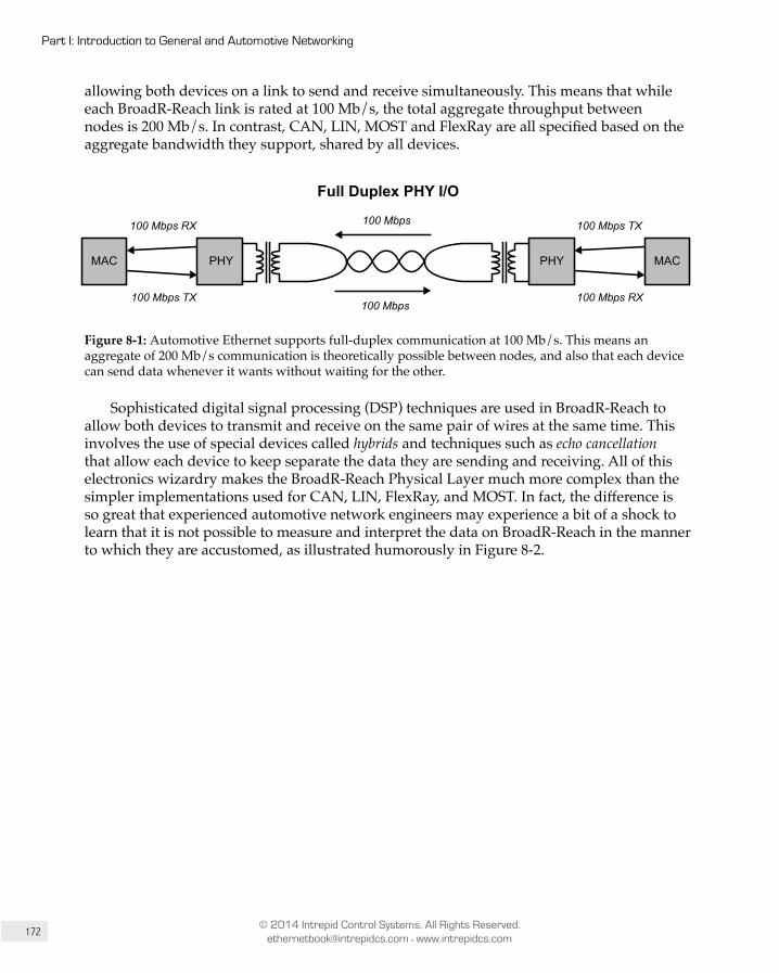
172
Part I: Introduction to General and Automotive Networking
© 2014 Intrepid Control Systems. All Rights Reserved. [email protected] • www.intrepidcs.com
allowing both devices on a link to send and receive simultaneously. This means that while each BroadR-Reach link is rated at 100 Mb/s, the total aggregate throughput between nodes is 200 Mb/s. In contrast, CAN, LIN, MOST and FlexRay are all specified based on the aggregate bandwidth they support, shared by all devices.
PHY PHYMAC MAC
100 Mbps RX
100 Mbps TX
100 Mbps
100 Mbps TX
100 Mbps RX
100 Mbps
Dual Simplex PHY I/O
Full Duplex PHY I/O
Full DuplexMAC I/O (MII)
Full DuplexMAC I/O (MII)
100 Mbps RX
100 Mbps TX
PHY
100 Mbps
100 Mbps TX
100 Mbps RX
MACPHYMAC
100 Mbps
Figure 8-1: Automotive Ethernet supports full-duplex communication at 100 Mb/s. This means an aggregate of 200 Mb/s communication is theoretically possible between nodes, and also that each device can send data whenever it wants without waiting for the other.
Sophisticated digital signal processing (DSP) techniques are used in BroadR-Reach to allow both devices to transmit and receive on the same pair of wires at the same time. This involves the use of special devices called hybrids and techniques such as echo cancellation that allow each device to keep separate the data they are sending and receiving. All of this electronics wizardry makes the BroadR-Reach Physical Layer much more complex than the simpler implementations used for CAN, LIN, FlexRay, and MOST. In fact, the difference is so great that experienced automotive network engineers may experience a bit of a shock to learn that it is not possible to measure and interpret the data on BroadR-Reach in the manner to which they are accustomed, as illustrated humorously in Figure 8-2.

173
Chapter 8: Comparing Traditional Automotive Networks to Ethernet
© 2014 Intrepid Control Systems. All Rights Reserved. [email protected] • www.intrepidcs.com
This Ethernet stuff sounds interesting, I would like to get a test bench setup and look at some eye-diagrams and scope traces.
WHAT!?!?
Ethernet is a closed-eye stream. It is not possible to measure the physical wires and interpret the data.
What if I measure the signal right at the trasmitter?
The line is not active unless there are RX/TX transactions and any signal you measure will be both TX and RX combined.
Could I tap the line to see what is going on?
The system uses active idle. Both idle and data symbols are scrambled. RX uses self-synchronizing descrambler, but good luck trying to figure out which is which. Only the transmitter itself easily knows how to extract the original RX signal.
How can it test it then?
The PHY chip can tell you from the DSP, signal quality, channel quality, and any channel or bit errors.
I can forget everything I know from the last 30 years about CAN, LIN, and FlexRay tools.
Figure 8-2: This hypothetical discussion between an automotive engineer and an Ethernet engineer underscores how different Automotive Ethernet is at the line level.
What is often a surprise to engineers new to modern Ethernet networks is that, at the basic Physical Layer level, they are constructed of only point-to-point lines—each UTP cable supports only two nodes, one on each end. Assuming we are dealing with a typical network containing more than 2 devices, a switch is used at the center to interconnect the devices on all of these links. To illustrate this, let’s suppose that we have a simple Automotive Ethernet network where there are 4 nodes. First, there’s an ECU containing a Head Unit and a 4-port switch; there’s also a Display node, a Console node, and a Speaker node. Each of the UTP cables from the switch to the 4 end nodes is physically distinct from the other; in this sense, there are really 4 “micro” Ethernet networks here. These are sometimes called network segments, and the process of laying out the overall network in this way is called
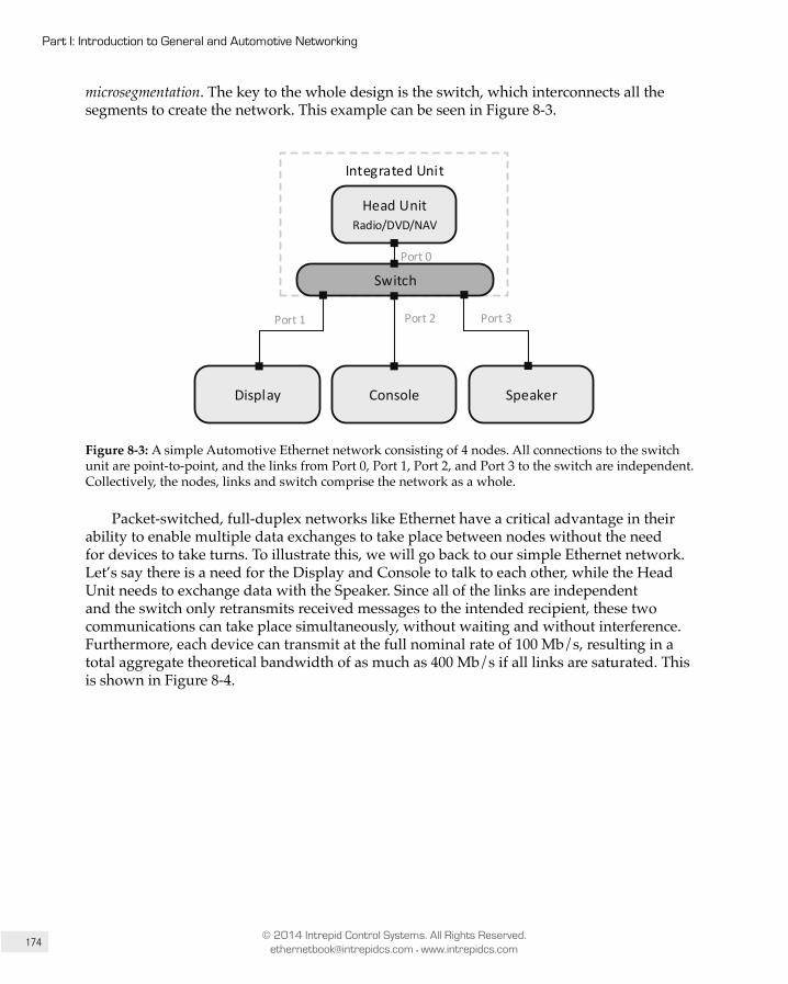
174
Part I: Introduction to General and Automotive Networking
© 2014 Intrepid Control Systems. All Rights Reserved. [email protected] • www.intrepidcs.com
microsegmentation. The key to the whole design is the switch, which interconnects all the segments to create the network. This example can be seen in Figure 8-3.
Switch
Head UnitRadio/DVD/NAV
Display Console Speaker
Integrated Unit
Port 0
Port 1 Port 2 Port 3
Figure 8-3: A simple Automotive Ethernet network consisting of 4 nodes. All connections to the switch unit are point-to-point, and the links from Port 0, Port 1, Port 2, and Port 3 to the switch are independent. Collectively, the nodes, links and switch comprise the network as a whole.
Packet-switched, full-duplex networks like Ethernet have a critical advantage in their ability to enable multiple data exchanges to take place between nodes without the need for devices to take turns. To illustrate this, we will go back to our simple Ethernet network. Let’s say there is a need for the Display and Console to talk to each other, while the Head Unit needs to exchange data with the Speaker. Since all of the links are independent and the switch only retransmits received messages to the intended recipient, these two communications can take place simultaneously, without waiting and without interference. Furthermore, each device can transmit at the full nominal rate of 100 Mb/s, resulting in a total aggregate theoretical bandwidth of as much as 400 Mb/s if all links are saturated. This is shown in Figure 8-4.
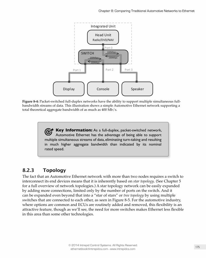
175
Chapter 8: Comparing Traditional Automotive Networks to Ethernet
© 2014 Intrepid Control Systems. All Rights Reserved. [email protected] • www.intrepidcs.com
Head UnitRadio/DVD/NAV
Display Console Speaker
Integrated Unit
Port 0
Port 1 Port 2 Port 3
SWITCH100Mbps
100Mbps
100Mbps
100Mbps
Figure 8-4: Packet-switched full-duplex networks have the ability to support multiple simultaneous full-bandwidth streams of data. This illustration shows a simple Automotive Ethernet network supporting a total theoretical aggregate bandwidth of as much as 400 Mb/s.
Key Information: As a full-duplex, packet-switched network, Automotive Ethernet has the advantage of being able to support
multiple simultaneous streams of data, eliminating turn-taking and resulting in much higher aggregate bandwidth than indicated by its nominal rated speed.
8.2.3 TopologyThe fact that an Automotive Ethernet network with more than two nodes requires a switch to interconnect its end devices means that it is inherently based on star topology. (See Chapter 5 for a full overview of network topologies.) A star topology network can be easily expanded by adding more connections, limited only by the number of ports on the switch. And it can be expanded even beyond that into a “star of stars” or tree topology by using multiple switches that are connected to each other, as seen in Figure 8-5. For the automotive industry, where options are common and ECUs are routinely added and removed, this flexibility is an attractive feature, though as we’ll see, the need for more switches makes Ethernet less flexible in this area than some other technologies.

176
Part I: Introduction to General and Automotive Networking
© 2014 Intrepid Control Systems. All Rights Reserved. [email protected] • www.intrepidcs.com
Switch
Node 1
Node 2 Node 3 Node 4
Integrated Unit
Port 0
Port 1 Port 2 Port 3
Figure 8-5: Simple Ethernet networks use star topology as we saw in Figure 8-3. They can, however, easily be expanded to more complex tree topologies as the number of nodes and subsystems grow, simply by interconnecting multiple switches.
The example we saw in Figure 8-4 represents a fundamentally different way of networking than that implemented by CAN, FlexRay, LIN, MOST, and even some obsolete versions of Ethernet. These older networking technologies are all based on a shared medium, which means that all devices can access the cabling that connects devices together. The shared nature of the medium not only prevents more than one device from transmitting at a time, it has another important effect as well: if any frame exists on the network, all nodes connected to the network can see it. But in a switched Ethernet network, under most circumstances, the sender will transmit a frame to the switch, which will then retransmit it only on the port connected to the intended recipient; other ports and links will be left idle.
As an example, let’s return again to our simple 4-node network. If the Console node transmits a frame intended for the Display node, as shown in Figure 8-6, the frame will first be carried on the link between the Display and Port 2 of the switch; a short time later, the switch will copy the frame to its Port 1, where it will travel to the Display. This has two important implications for anyone accustomed to CAN. First, for most of the transmission, parts of two frames will exist on this network at the same time: one traveling from Console to the switch, and another from the switch to the Display. Second, the frame will never exist on the segments of the network leading to devices that are neither the source nor destination; here, the links to the Head Unit and Speaker are not involved in this transaction, and so Ports 0 and 3 remain idle, as will the cables attached to them.
This in turn has profound consequences when it comes to the use of tools in automotive network. The idea of hooking up a CAN tool like a neoVI-Fire or ValueCAN to the network to monitor and/or simulate message traffic goes out the window, because there is no single place on the network where all traffic can be seen. Hooking a tool to a link on an Ethernet network will only show the frames on that link, not everything on the network as is the case with older technologies. We will explain this more when we discuss tools later in the book.

177
Chapter 8: Comparing Traditional Automotive Networks to Ethernet
© 2014 Intrepid Control Systems. All Rights Reserved. [email protected] • www.intrepidcs.com
Switch
Head UnitRadio/DVD/NAV
Display Console Speaker
Integrated Unit
Port 0
Port 1 Port 2 Port 3
Figure 8-6: In Ethernet, frames appear only on the legs of the network where there is a source or destination node. Here a message from Console to Display will only appear on the links between the Console and switch Port 2, and between switch Port 1 and the Display. The frame will never appear on the links to Ports 0 or 3.
Key Information: With CAN, LIN, FlexRay, and MOST, it is possible to connect a tool like neoVI-Fire, neoVI-ION, or ValueCAN
to the network to monitor and/or simulate any and all traffic. For Ethernet, this is not possible, because messages are only sent on the portions of the network where they are required.
8.2.4 Frame FormatEthernet uses several different frame formats, most of which are quite similar, differing only in the precise details of certain fields they contain and where they are located. These are covered thoroughly in Chapter 11; here we will provide only a brief overview of one of the most common frame formats, to allow us to compare it to the formats used in other networks (Figure 8-7).
6 6 2 446 to 1,500
Preamble
7 1
SOF Destination Address Source Address
4
802.1Q (VLAN) Type Data FCS
Figure 8-7: One of the most common Ethernet frame formats, usually called Ethernet II, including Type (“Ethertype”) and VLAN tag fields.
178
Part I: Introduction to General and Automotive Networking
© 2014 Intrepid Control Systems. All Rights Reserved. [email protected] • www.intrepidcs.com
Below is a brief explanation of each of these fields.
PreambleA series of 7 bytes of alternating 1s and 0s that indicates that a frame is coming, and enables synchronization of the transmitter and receiver.
Start of Frame Delimiter (SOF)This is a single byte with alternating 1s and 0s but with the last 0 changed to a 1 resulting in the pattern “10101011”. This signals to the receiver that the “introduction” to the frame is ending and that what comes next is the actual Ethernet frame.
Destination and Source AddressesThe Destination Address and Source Address numbers are the fundamental addressing mechanism for Ethernet. Each consists of a 6-byte address which is split into a 3-byte organization number and a 3-byte device number.
This leads to our first fundamental difference when comparing Ethernet to CAN, LIN, and FlexRay. Inherent in all Ethernet communication is the idea that each frame has a source and either one or multiple destinations. In the other automotive network types, the transmitter of a frame is not defined based on the frame itself—without additional external information—and all nodes always receive all frames and then decide whether or not to use the frame contents. Another implication of Ethernet frame addressing is that the data payload in a frame is not differentiated solely by information in the header as is the case most of the time for CAN and LIN. We will explain this further in the sections on CAN, LIN, FlexRay, and MOST, later in this chapter.
802.1Q (VLAN / Frame Priority) TagThis is an optional 4-byte field defined in IEEE 802.1Q that is used to implement virtual local area networking (VLAN) functionality and also to specify a frame’s priority level. In Automotive Ethernet, it is arguably only “technically” optional because it is used widely in applications such as Audio Video Bridging (AVB) for real-time streaming.
Type and Data (Payload)The Type field is more commonly called the Ethertype; despite its name, this does not describe the type of Ethernet being used, but rather the type of data being carried within the Data (or Payload) field.
As we saw in our look at the OSI Reference Model in Chapter 7, modern networks are designed around the principles of layering and data encapsulation. The Ethertype generally indicates what layer 3 protocol message is encoded in the (layer 2) Ethernet frame. There are also a number of special values used for this field to implement a variety of features, such as virtual LANs. The most famous Ethertype is the value of 0x800, which means the frame is carrying an Internet Protocol version 4 (IPv4) packet. This packet itself has its own headers and payload, such as those of a Transmission Control Protocol (TCP) segment or User Datagram Protocol (UDP) datagram. And these in turn have more headers and encapsulated data, going up to the level of the application. This is a very different system than the one used in CAN, for example, where the data section after the Arbitration ID and control fields
179
Chapter 8: Comparing Traditional Automotive Networks to Ethernet
© 2014 Intrepid Control Systems. All Rights Reserved. [email protected] • www.intrepidcs.com
generally carries the actual data, such as Engine RPM, temperature and so forth, without layering or encapsulation.
Frame Check Sequence (FCS)The FCS field contains a 32-bit cyclic redundancy check (CRC) value calculated and filled in by the transmitter. The receiver of the frame, after reading its contents, also calculates a CRC value using the same formula, and compares it against the value that the transmitter sent. If there is a mismatch, this indicates corruption of the frame during transmission, and the frame is discarded.
Not only is the frame dropped, but no notification or error message is generated to indicate that this has happened. Engineers accustomed to CAN will not like this somewhat harsh reality about Ethernet: nodes or switches can drop frames and there is no way at the Ethernet level to know that any problem occurred. (Ethernet is intentionally designed this way for the sake of performance, and relies on higher-layer protocols such as TCP to detect lost messages and retransmit them if that functionality is required.) This is one reason a tool like VehicleSpy is useful: it has the ability to detect bad frames and inform the user of their occurrence, while any tool that uses a standard switch or computer will never display bad frames.
8.2.5 Media Access Control Ethernet was originally well-known for its unique media access control method called Carrier Sense Multiple Access with Collision Detection or CSMA/CD. This technique laid out the specific rules governing how devices determined when they could transmit, and the methods for detecting and retransmitting frames if collisions occurred as a result of more than one device deciding to send data at the same time. CSMA/CD was such a defining part of Ethernet that it was mentioned in the title of every IEEE 802.3 overall Ethernet standard up until the 2012 version.
The reason it has now been removed from the title is that modern Ethernet networks are no longer based on shared media, and therefore have no need for the CSMA/CD mechanism. As mentioned above, every device can send and receive simultaneously, at will. Collisions were a normal part of older shared Ethernet networks but now should not occur unless there is a configuration problem or malfunction on the network.
In effect, modern Ethernet networks, including those used in Automotive Ethernet, have no media access control method at all. With networks composed of point-to-point full duplex links, there is no media that we need to control access to!
Key Information: Automotive Ethernet networks, like other modern forms of Ethernet, are based on point-to-point, full-duplex
links, rather than a shared medium. For this reason, they effectively have no need for media access control at all: any device can transmit at any time without having to worry about collisions or interference with other nodes.

180
Part I: Introduction to General and Automotive Networking
© 2014 Intrepid Control Systems. All Rights Reserved. [email protected] • www.intrepidcs.com
8.2.6 Advantages All of Chapter 1 is dedicated to explaining the many advantages of Ethernet over other vehicle network technologies, and we mentioned many of them at the start of this chapter as well, so it would be redundant to repeat everything here yet again. We will simply reiterate that the advantages of Ethernet are numerous and substantial.
8.2.7 DisadvantagesNobody’s perfect, and no technology is either. And so, while Ethernet promises many important benefits to automotive networks, it has some drawbacks as well.
In the world of electronics, virtually all newer, faster technologies are more expensive than more mature, slower ones. There are numerous reasons for this, including lower production costs, more suppliers in the marketplace, and less demand for something seen as new and exciting. In the case of Ethernet, there’s another cost consideration that also must be taken into account: switches are the key to much of AE’s beneficial characteristics, but they also represent an additional piece of hardware that needs to be added to each network. Furthermore, switches tend to be intelligent and high-performance devices, adjectives that often imply high cost as well.
With Ethernet’s star topology, every node must be linked back to a single connection point, a switch, which leads to more restrictive requirements in terms of cabling. Adding more switches to the network can lead to a tree topology with greater network configuration flexibility, but this means added cost in the form of the switches themselves. The higher transmission speeds of AE also means there is less leniency when it comes to how much wire can be untwisted before terminating a cable at a connector, which adds complexity to cable design and implementation.
Another important implication of point-to-point switched networks is that every end node connection requires a switch port. As we discussed in Chapter 2, cost is a major concern for automobile manufacturers, so network designers have to play a delicate balancing act in deciding how many ports to use for their switches. Extra ports provide room for expansion, but add unnecessary cost if they are never used; on the other hand, not having any open ports means that expansion is impossible unless the switch is replaced with a larger one, or another switch is added, which may increase cost even more.
Flexibility is also important, especially considering that a network system is often designed for multiple platforms and vehicles that have numerous options. A single assembly line might have one car with a network consisting of 4 nodes and a switch, followed by another car with the same switch but 5 nodes. In this case, in the 4-node vehicle an Ethernet port and all associated circuitry and connectors represents wasted cost. In contrast, CAN, LIN, FlexRay, and MOST use bus or ring topologies and so can add nodes without incurring additional hardware costs or having to make these sorts of choices in advance.
Finally, in the automotive industry, engineering and testing tools are an integral and essential part of the development process. As explained earlier, the application of these tools, like Vehicle Spy, is much different with Ethernet than it is with older network types. It is not possible to simply attach a tool to a physical data line to monitor and simulate traffic. In fact, it is not possible to simply attach any tool to the data lines of AE without disturbing the network. Generally what is required is to not break the data lines, but rather insert an active test access point (TAP) into the network, or alternatively, use a debug port on the switch with

181
Chapter 8: Comparing Traditional Automotive Networks to Ethernet
© 2014 Intrepid Control Systems. All Rights Reserved. [email protected] • www.intrepidcs.com
port mirroring to monitor traffic. Both of these methods have their own issues, however. We will discuss this topic in more detail in Chapter 38.
8.3 Controller Area Network (CAN) and CAN with Flexible Data Rate (CAN-FD)
For more than 30 years, CAN has been the dominant network in the automotive industry; one simply cannot understate the impact CAN has had on in-vehicle networking and the automobile world as a whole. There are very good reasons why CAN has been so successful, and will continue to be so even with the introduction of Automotive Ethernet.
CAN has been around so long and is so well-known that many in the industry have become accustomed to advantages that are unique to it, and may even assume that these characteristics are inherent to every networking technology. But this is the not the case, even though it may only become apparent when directly comparing CAN to other network types. Some of the key benefits of CAN include the following:
• CAN is a robust and proven network. For decades, CAN has been the primary network of choice for nearly every automobile manufacturer worldwide.
• CAN is an open ISO 11898 standard, and as a result, there are a large variety of CAN controllers available from many manufacturers. This provides the flexibility to select the exact silicon that is needed for a given application.
• Because of its widespread availability, and the competitive climate that results from its open status and longevity, CAN is one of the lowest-cost networks to implement in a vehicle.
• CAN is the closest thing in the automotive networking world to being “plug and play”. Nodes can be added or removed, at least within certain limits, without the need to change other nodes, software, or other network parameters.
• Tools are easy to use with CAN. Just like adding and removing a node, tools like the ValueCAN, neoVI-FIRE and others can be connected to the network and immediately begin participating as a receiver—of all frames—or as a transmitter.
For brevity’s sake, we will only cover the CAN 2.0 standard as described in ISO11898-1 (the Data Link layer) and ISO11898-2 (the Physical Layer). We have skipped other forms of CAN, like GM’s Single Wire CAN (SAE J2411) and Low Speed Fault Tolerant CAN (ISO11898-3). We will also only briefly mention some key points about the new CAN with Flexible Data Rate (CAN-FD) standard, as it is similar to CAN, just with some modifications.
8.3.1 BackgroundThe Controller Area Network (CAN) was introduced to the public by Bosch in a paper at the 1986 SAE Congress in Detroit (SAE 860391). The paper proposed that vehicles could be improved by sharing data among multiple ECUs. The main example given in the paper was the durability improvements that could be made if a transmission controller could give the engine controller a command to reduce torque just before a gear shift, and then a command to resume torque just afterwards—this would result in reduced clutch wear as a result of

182
Part I: Introduction to General and Automotive Networking
© 2014 Intrepid Control Systems. All Rights Reserved. [email protected] • www.intrepidcs.com
the lower torque during the gear shift. Today, this type of communication is commonplace among many ECUs in the vehicle.
It’s also important to understand that CAN’s original intent was to transmit predominantly sensor, actuator and other control signal data between ECUs, and therefore to eliminate the need for redundant wiring and sensors. Looking at the CAN networks in a modern car on the road today, we can see that CAN has achieved this goal quite well.
8.3.2 Physical LayerLike Automotive Ethernet, CAN is implemented using UTP copper cabling. The two wires are designated as CAN_H for CAN High, and CAN_L for CAN Low, and the signals on the twisted pair cables are driven differentially with a nominal voltage of 2.5V when measured from node ground. Unlike BroadR-Reach, CAN works on a binary signaling system, the two states being dominant (a logical 0) and recessive (a logical 1). A dominant state is indicated by the CAN_H voltage moving up by a nominal value of 1V and CAN_L moving down by a nominal value of 1V making the differential signal 2V.
Although there are many commercial isolated transceivers available, there is nothing in the CAN specification itself that requires electrical isolation; if none is implemented, CAN is designed for maximum ground offsets of about 1.2V.
8.3.3 Topology CAN uses a bus topology, one key difference between it and some other network types such as modern Ethernet (though earlier Ethernet Physical Layers were also bus-based). A bus topology means that each node participating on the network is physically connected to all other nodes, with the resulting bus representing a shared access medium. It is also possible to have a simple point-to-point 2-node network, but this is seldom used in cars.
In a typical multi-node bus, each node is electronically connected to all the other nodes over the same twisted pair. It is possible to also consider CAN a multi-drop or linear bus, where each ECU can branch a small distance from the main trunk of the bus. As we will explain, this topology is what gives CAN some of its best qualities—and also some of its biggest drawbacks.
A good quality of this topology is that the wiring and interconnections between nodes is simple. Also, the order of the nodes on the network is not important, and as long as the maximum bus length is not exceeded, the network designer can wire the nodes together in any convenient way.
In a bus topology, however, it is not possible for multiple nodes to transmit at the same time without the potential for collisions, so some method is needed for nodes to avoid frame collisions, arbitrate in case of a collision, or provide some collision detection and retry mechanism. CAN supports a very clever non-destructive arbitration mechanism that we will explain shortly.
A further effect of a true bus network is that it is a shared medium; when any node transmits a frame, it is seen across the entire bus. Therefore, all nodes on a CAN bus combined have a total of only 1 Mb/s of theoretical throughput across the entire network.
For standard 1 Mb/s CAN, the ISO 11898 standard specifies a maximum bus length of 40 m, with a maximum of 30 nodes allowed, each with a stub length maximum of 0.3 m. More nodes can be supported if the network runs at a lower speed, and the bus can be made longer
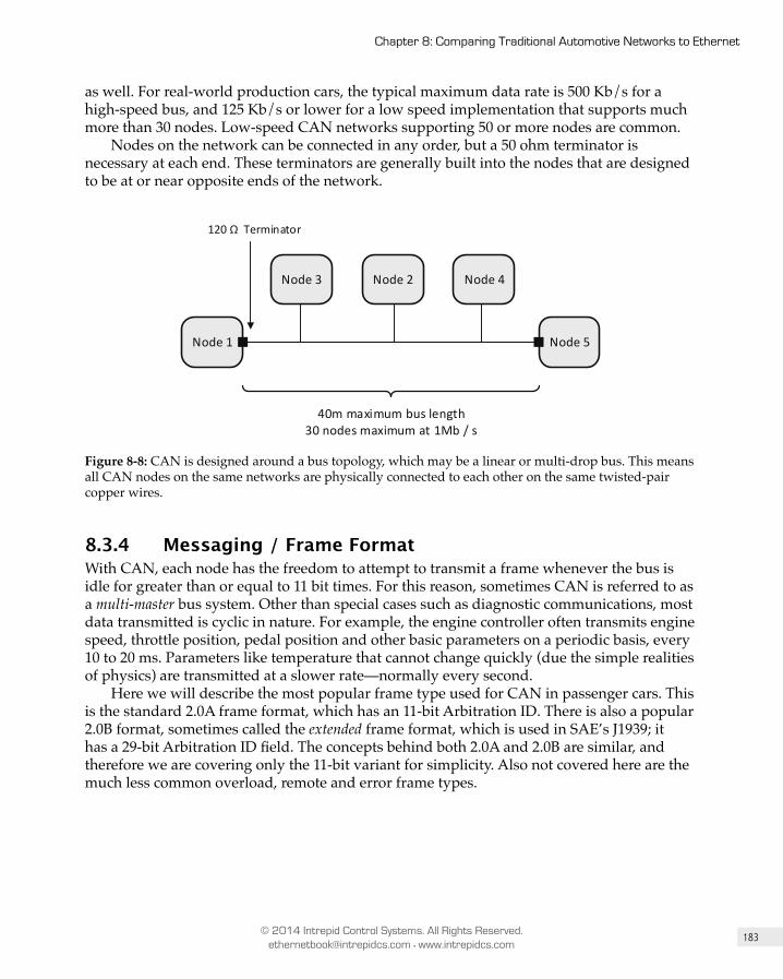
183
Chapter 8: Comparing Traditional Automotive Networks to Ethernet
© 2014 Intrepid Control Systems. All Rights Reserved. [email protected] • www.intrepidcs.com
as well. For real-world production cars, the typical maximum data rate is 500 Kb/s for a high-speed bus, and 125 Kb/s or lower for a low speed implementation that supports much more than 30 nodes. Low-speed CAN networks supporting 50 or more nodes are common.
Nodes on the network can be connected in any order, but a 50 ohm terminator is necessary at each end. These terminators are generally built into the nodes that are designed to be at or near opposite ends of the network.
Node 1
Node 2Node 3 Node 4
40m maximum bus length30 nodes maximum at 1Mb / s
Node 5
120 Ω Terminator
Figure 8-8: CAN is designed around a bus topology, which may be a linear or multi-drop bus. This means all CAN nodes on the same networks are physically connected to each other on the same twisted-pair copper wires.
8.3.4 Messaging / Frame Format With CAN, each node has the freedom to attempt to transmit a frame whenever the bus is idle for greater than or equal to 11 bit times. For this reason, sometimes CAN is referred to as a multi-master bus system. Other than special cases such as diagnostic communications, most data transmitted is cyclic in nature. For example, the engine controller often transmits engine speed, throttle position, pedal position and other basic parameters on a periodic basis, every 10 to 20 ms. Parameters like temperature that cannot change quickly (due the simple realities of physics) are transmitted at a slower rate—normally every second.
Here we will describe the most popular frame type used for CAN in passenger cars. This is the standard 2.0A frame format, which has an 11-bit Arbitration ID. There is also a popular 2.0B format, sometimes called the extended frame format, which is used in SAE’s J1939; it has a 29-bit Arbitration ID field. The concepts behind both 2.0A and 2.0B are similar, and therefore we are covering only the 11-bit variant for simplicity. Also not covered here are the much less common overload, remote and error frame types.

184
Part I: Introduction to General and Automotive Networking
© 2014 Intrepid Control Systems. All Rights Reserved. [email protected] • www.intrepidcs.com
12 6 160 to 8 bytes
Header Footer
SOF
1
Arbitration Control payload CRC Ack
2 7
End of Frame
Figure 8-9: Standard CAN 2.0A frame format.
Figure 8-9 shows the standard CAN 2.0A frame format; a description of its fields can be found below.
SOFThe Start of Frame is a single dominant bit that is transmitted by one or more nodes intending to send a frame. It signals the beginning of a frame (or arbitration for the right to send a frame) and is used to “hard synchronize” devices on the bus. A transmitter is allowed to start a frame only if there have been at least 11 consecutive bits of recessive states on the bus prior to initiation.
Arbitration The arbitration field consists of 12 bits, where the first 11 are referred to as the Arbitration ID. One of this field’s primary functions is to implement CAN’s media access control mechanism as described later in this section, but it has another use as well. As many automotive network engineers are aware, CAN has a frame-based structure where the Arbitration ID not only determines the priority of a message—zero being the highest priority—but also generally identifies the payload of the frame as well.
There are very popular network description files for CAN used in network engineering tools like Vehicle Spy, such as *.dbc, or the newer industry standard AUTOSAR format *.arxml. These files allow frame IDs to be decoded to indicate their meaning. For example, a CAN frame with an ID of 0x321 has a payload with Engine RPM, Pedal and Throttle position. This is very different than Ethernet, where the frame header almost never identifies the payload of the data; only the frame’s source, destination, and payload type.
The 12th bit in the Arbitration Field is labeled RTR for remote transfer request and is largely unused today. In fact, the most recent form of CAN—CAN-FD—has no RTR field.
Control The control field for a standard 11-bit frame consists of a dominant IDE flag—which is recessive in the case of an extended frame (29 bit ID field)—a reserved bit and a 4-bit Data field. The Data field determines the length of data in the Data or payload section of the frame. For ISO11898-1 any value is allowable in the 4 bit field but any value of 8 or greater means a data payload length of 8. In the newer CAN-FD specification, values greater than 8 mean the data payload is larger than 8, up to a maximum of 64 bytes.
185
Chapter 8: Comparing Traditional Automotive Networks to Ethernet
© 2014 Intrepid Control Systems. All Rights Reserved. [email protected] • www.intrepidcs.com
Data The Data field carries the data payload of the message and can be anywhere from 0 to 8 bytes for ISO11898 CAN or a maximum of 64 bytes for CAN-FD.
CRCThe Cyclical Redundancy Check field is 16 bits long for an ISO11898 frame, consisting of a 15-bit CRC value and a single recessive CRC delimiter bit. The transmitter of a frame calculates this value based on an efficient algorithm given in the specification and transmits the calculated value in this field. All receivers compare their own calculation of this value with the one transmitted. If there is a mismatch or other error by any receiver, the next field, Ack, comes into play.
AckThe Acknowledge Field is used for all receivers on the bus to signal to the transmitter that the CRC matched, and the entire frame was received correctly. If any node correctly receives the frame without an error, this bit is set to dominant by transmitter, signifying that it transmitted the message correctly. If a receiver detects a problem, it will overwrite the Ack bit with an error frame informing all participants of the problem.
End of FrameA succession of seven recessive bits indicate the end of a frame.
8.3.5 Media Access Control All shared bus networks require some media access control (MAC) method to ensure orderly use of this communal resource. CAN uses a clever method that allows devices to begin transmissions simultaneously without causing collisions, and for the station with the highest-priority message to continue transmitting while those with lower-priority ones automatically back off.
The key to this system is the Arbitration field mentioned above, and the fact that all devices listen on the bus as they transmit. At any time that the bus is detected as being idle, a station may begin sending a frame by transmitting a Start of Frame (SOF) dominant bit, which is used by all devices on the bus to synchronize their clocks. Thus, if multiple devices see the bus idle and try to send SOF at once, they will all detect the others’ bits, and synchronize based on the first SOF seen on the bus.
Once this “hard synchronization” is completed, any device that wishes to transmit a frame during this frame period begins to send its 11-bit Arbitration ID one bit at a time. Each device sends either a recessive (1) bit or a dominant (0) bit. The bus is configured in the equivalent of a “logical AND” operation, so that if all devices send a 1, the bus remains at 1, and there is effectively a “tie”. However, if even one device sends a dominant (0) bit, the bus will be pulled to a 0 value. When this happens, any device that sent a 0 bit continues with the arbitration, while any device that sent a 1 “drops out” and attempts to send its frame later. If only one device asserted a 0 bit, it wins the arbitration, while if multiple stations sent a 0, the process is repeated for the next bit, and then the next one, until there is a winner. The Arbitration IDs are selected so that higher-priority messages have dominant bits “earlier”

186
Part I: Introduction to General and Automotive Networking
© 2014 Intrepid Control Systems. All Rights Reserved. [email protected] • www.intrepidcs.com
in the ID than lower-priority messages, so they will always be sent first in the event of contention.
This system is very different from the one used in traditional shared Ethernet, where collisions can occur that result in all of the messages needing to be retransmitted. The CAN arbitration scheme is called non-destructive because one message will always win and have its frame be sent even in the event of competition. However, this is only possible because of the ability of the stations to be synchronized so their Arbitration ID bits are sent at approximately the same time. This in turn requires relatively short bus lengths and slow transmission speeds.
8.3.6 A Note on CAN-FD CAN with Flexible Data Rate or CAN-FD is the latest variant of CAN. The specification is owned by Bosch, its developer, but the specification is freely available for reading. In CAN 2.0 the maximum achievable bit rate is 1 Mb/s, a limit that is largely imposed by the arbitration method, as described above. Because arbitration is not needed during the transmission of other parts of a frame, it is possible to increase the bit rate during the control, payload and CRC sections. CAN-FD maintains the 1 Mb/s speed during arbitration, and then sends these other parts of the frame at up to 8 Mb/s.
Another limitation of original CAN is its 8-byte frame size, which is not adequate for modern networks. The engineers at Bosch reformulated the CRC calculation so that the payload can increase from 8 bytes to 64 while maintaining CAN 2.0’s error detection robustness (in math terms, they modified it while maintaining the same Hamming distance).
8.3.7 Advantages You don’t become an industry standard for decades without having a lot going for you, and so it is with CAN. We began this section with an overview of some of CAN’s advantages in general terms, but will now look at them in more detail, and with particular attention to where CAN provides benefits relative to Ethernet.
One of CAN’s greatest benefits is its flexibility. Its multi-master system, with no special-purpose nodes or interconnection devices like switches, enables network designers to add and remove ECUs easily without any need to redesign the network or make changes to other devices. In contrast, switched Ethernet networks require a port for each switch, forcing designers to choose between leaving open ports on switches (which adds cost up front) or restricting expandability (which may increase cost later on). Adding a significant number of Ethernet ECUs may even require restructuring the network to ensure efficiency.
Another important aspect of flexibility with CAN is that tools like Vehicle Spy with a neoVI-FIRE can be simply plugged into a CAN network, and then receive all messages and even participate on the network like any other ECU. Simulators and tools for CAN are relatively simple compared to other networks. As we saw earlier in the chapter, this is not the case for Automotive Ethernet, due to the use of many switched links.
Bus topology provides the most flexible type of wiring. Engineers can simply connect ECUs in nearly any order, with the only limitation that the ends of the network be terminated. Again, switched Ethernet imposes limitations on how devices are connected, especially if there are many nodes.
187
Chapter 8: Comparing Traditional Automotive Networks to Ethernet
© 2014 Intrepid Control Systems. All Rights Reserved. [email protected] • www.intrepidcs.com
CAN’s long history, industry dominance, large number of suppliers, low speed, and lack of a need for interconnection devices combine to keep its cost very low. Ethernet will be more expensive, especially at first.
As we highlighted in Chapter 1, the automotive industry is highly risk-averse and for very good reason. With billions of CAN nodes running in millions of vehicles over the course of decades, CAN has proven itself to be safe and reliable. While Ethernet has a long pedigree of its own, it was not earned in the automotive industry, and it will take time until trust can be built in this area.
8.3.8 DisadvantagesThe primary disadvantage of CAN, by a large margin, it is low performance. Throughput needs are constantly increasing in the world of computers and networks, and CAN’s maximum 1 Mb/s speed is simply not up to the task of handling many modern applications. Over time, this slow speed will limit CAN’s scope, and shift its role from overall vehicle dominance to being the network of choice only for traditional, low-speed uses. Even the newer CAN-FD only offers a maximum speed of 10 Mb/s, one tenth of what BroadR-Reach can provide, and an even smaller fraction of what newer Automotive Ethernet types are likely to offer before the end of the decade.
Not only is CAN much slower than Ethernet, it is also less efficient. Because of its 8-byte payload maximum, a CAN frame has very high overhead: it transmits more bits in its header and footer fields than it does bits of data. Again, CAN-FD improves this limit to 64 bytes, but this is not in the same league as Ethernet’s 1,500 bytes.
8.4 FlexRay Like CAN, FlexRay was created by engineers in the automotive industry to address network needs that are unique to automotive environments. It was designed to support safety critical “x-by-wire” applications, such as steer-by-wire, brake-by-wire and so on. The main features of FlexRay include the following:
• Nodes share the same very accurate time base, to enable precise safety-critical real-time communications across multiple nodes.
• FlexRay controllers and active stars come in a dual package that offers inherent redundancy, also important for safety-critical x-by-wire applications.
• FlexRay is built upon time-triggered messaging that ensures that any safety-critical messages are able to be transmitted and received with little delay or jitter.
• FlexRay was designed to provide the highest level of reliability, with a dual-channel structure for redundancy.
• FlexRay offers 10 times the maximum theoretical bandwidth per channel of CAN, and this doubles when considering its dual independent channels.
FlexRay can be configured in more than one topology. Like CAN, LIN, and MOST, it also inherently supports power management, sleep modes, and fast wake-up times, all important for automotive networks.
188
Part I: Introduction to General and Automotive Networking
© 2014 Intrepid Control Systems. All Rights Reserved. [email protected] • www.intrepidcs.com
8.4.1 BackgroundLong before there was any serious consideration of putting Ethernet in cars on a widespread basis, there was a desire for more speed and better real-time and safety-critical capabilities than CAN has the ability to provide. In 2000, the FlexRay Consortium was formed by lead members BMW, Daimler, Bosch and others, to create and standardize a new network type that addressed some of the deficiencies of CAN for x-by-wire applications.
In 2006, to much fanfare, BMW produced the first vehicle to feature FlexRay technology. Remembering the excitement surrounding FlexRay in the mid-2000s invokes a sense of deja vu when thinking about Automotive Ethernet today. Back then, new companies were created around the technology because it was expected to be “the next big thing”—companies that are now mostly defunct. Despite its advantages, FlexRay was much more complicated to implement than CAN, and some of its advantages forced less flexibility in the way that the more time critical messages work in the Static Segment of the messaging system; we’ll get into this more later in this section. These issues hampered FlexRay’s early success, and then when the Great Recession hit in 2008, it stopped the spread of FlexRay in its tracks. By the time the Great Recession was over, car companies, most notably BMW, had moved on from FlexRay and begun to investigate the possibility of Ethernet in vehicles.
8.4.2 TopologyFlexRay is designed to be flexible in its topology options: linear bus, passive star, active star, and point-to-point topologies are all supported. In a solely linear bus topology, the maximum network length is 24 meters with a maximum of 22 nodes; these numbers increase if an active star is used in the network. An active star is essentially the same concept as a hub of the sort commonly used in Ethernet networks in the 1990s: a multiport repeater. The active star is a way for the different parts of a network to be electrically isolated from each other, thereby separating the Physical Layer into sections that can each have a length of 24m and a max node count of 22. There is a maximum 250 ns frame delay allowed across the star, and because of this, the number of active stars in a single network is limited to 2. This limits the total maximum number of nodes allowable to 64. Frames on all legs of the star are essentially the same. Like CAN, MOST and older shared Ethernet, but unlike switched Ethernet, the maximum bandwidth of the network is 10 Mb/s shared among all connected nodes.
It should be noted that in FlexRay not all nodes are treated equal; some are designed as startup nodes, which are responsible for getting the network up and running. The exact procedure for this is beyond the scope of this book, but one should be aware that FlexRay networks are not strictly multi-master nor peer-to-peer networks, because of these special network roles.

189
Chapter 8: Comparing Traditional Automotive Networks to Ethernet
© 2014 Intrepid Control Systems. All Rights Reserved. [email protected] • www.intrepidcs.com
Node 1
Node 2Node 3 Node 4
Max. 24m between any 2 nodesMax. 22 nodes without an active star
Node 5
80-10 Ω Terminator
Figure 8-10: A FlexRay Network configured as a linear bus.
Node 1
Node 2Node 3 Node 4
Node 5
Figure 8-11: A FlexRay in a hybrid star topology.
FlexRay’s topology shares many of the same advantages and disadvantages as CAN’s. Wiring for a bus topology is very flexible, but it is not possible for multiple nodes to transmit at the same time. As we mentioned in the section on CAN, this means some method must be employed to handle the potential for collisions. In FlexRay, this is accomplished through a collision avoidance messaging system as we will explain below.
8.4.3 Messaging / Frame FormatThere is only one data-carrying frame format in FlexRay, which is used for both the Static and Dynamic Segments. Like CAN and LIN, but unlike Ethernet, there is no inherent concept of node addresses built into the messaging system. Messages essentially have specific IDs that—in most cases—uniquely identify the payload.
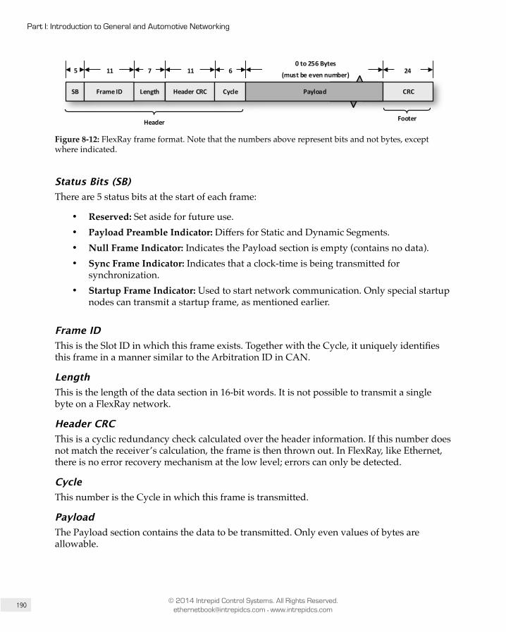
190
Part I: Introduction to General and Automotive Networking
© 2014 Intrepid Control Systems. All Rights Reserved. [email protected] • www.intrepidcs.com
5 240 to 256 Bytes
(must be even number)
SB
11
Frame ID Length
7 11
Header CRC Cycle
6
Header Footer
Payload CRC
Figure 8-12: FlexRay frame format. Note that the numbers above represent bits and not bytes, except where indicated.
Status Bits (SB)There are 5 status bits at the start of each frame:
• Reserved: Set aside for future use.• Payload Preamble Indicator: Differs for Static and Dynamic Segments.• Null Frame Indicator: Indicates the Payload section is empty (contains no data).• Sync Frame Indicator: Indicates that a clock-time is being transmitted for
synchronization.• Startup Frame Indicator: Used to start network communication. Only special startup
nodes can transmit a startup frame, as mentioned earlier.
Frame IDThis is the Slot ID in which this frame exists. Together with the Cycle, it uniquely identifies this frame in a manner similar to the Arbitration ID in CAN.
LengthThis is the length of the data section in 16-bit words. It is not possible to transmit a single byte on a FlexRay network.
Header CRCThis is a cyclic redundancy check calculated over the header information. If this number does not match the receiver’s calculation, the frame is then thrown out. In FlexRay, like Ethernet, there is no error recovery mechanism at the low level; errors can only be detected.
CycleThis number is the Cycle in which this frame is transmitted.
PayloadThe Payload section contains the data to be transmitted. Only even values of bytes are allowable.
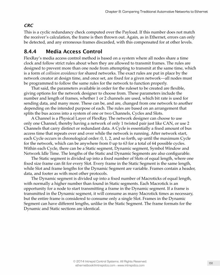
191
Chapter 8: Comparing Traditional Automotive Networks to Ethernet
© 2014 Intrepid Control Systems. All Rights Reserved. [email protected] • www.intrepidcs.com
CRCThis is a cyclic redundancy check computed over the Payload. If this number does not match the receiver’s calculation, the frame is then thrown out. Again, as in Ethernet, errors can only be detected, and any erroneous frames discarded, with this compensated for at other levels.
8.4.4 Media Access Control FlexRay’s media access control method is based on a system where all nodes share a time clock and follow strict rules about when they are allowed to transmit frames. The rules are designed to prevent more than one node from attempting to transmit at the same time, which is a form of collision avoidance for shared networks. The exact rules are put in place by the network creator at design time, and once set, are fixed for a given network—all nodes must be programmed to follow the same rules for the network to function properly.
That said, the parameters available in order for the ruleset to be created are flexible, giving options for the network designer to choose from. These parameters include the number and length of frames, whether 1 or 2 channels are used, which bit rate is used for sending data, and many more. These can be, and are, changed from one network to another depending on the intended purpose of each. The rules are based on an arrangement that splits the bus access into a system of one or two Channels, Cycles and Slots.
A Channel is a Physical Layer of FlexRay. The network designer can choose to use only one Channel, thereby having a network of only 1 twisted pair just like CAN, or use 2 Channels that carry distinct or redundant data. A Cycle is essentially a fixed amount of bus access time that repeats over and over while the network is running. After network start, each Cycle occurs in chronological order: 0, 1, 2, and so forth, up until the maximum Cycle for the network, which can be anywhere from 0 up to 63 for a total of 64 possible cycles. Within each Cycle, there can be a Static segment, Dynamic segment, Symbol Window and Network Idle Time. The lengths of the Static and Dynamic Segments are also configurable.
The Static segment is divided up into a fixed number of Slots of equal length, where one fixed size frame can fit for every Slot. Every frame in the Static Segment is the same length, while Slot and frame lengths for the Dynamic Segment are variable. Frames contain a header, data, and footer as with most other protocols.
The Dynamic segment is divided up into a fixed number of Macroticks of equal length, with normally a higher number than found in Static segments. Each Macrotick is an opportunity for a node to start transmitting a frame in the Dynamic segment. If a frame is transmitted in the Dynamic segment, it will consume as many Macrotick times as necessary, but the entire frame is considered to consume only a single Slot. Frames in the Dynamic Segment can have different lengths, unlike in the Static Segment. The frame formats for the Dynamic and Static sections are identical.
192
Part I: Introduction to General and Automotive Networking
© 2014 Intrepid Control Systems. All Rights Reserved. [email protected] • www.intrepidcs.com
Unused Slots Minislots
Static Segment
Cycle 0
0ms
Cycle 1
1ms
Cycle 2
2ms
Cycle 3
3ms
Av
Av
Av
Av
Ax
Ax
By
By
Bz
Bz
Ag
Ag
Bh
Bh
Ai
Bu
Bu
Bu
Bu
At
Slot 2Slot 1 Slot 3
Dymamic Segment
Nodes = A,B
Frames = g,h,I,t,u,v,x,y,z Slot 8 Slot 9 Symbol WindowSlot 10 (unused)
Network Idle TimeSlot 4 Slot 5
Figure 8-13: Example of a series of 4 Cycles on a single FlexRay channel.
As an example of how all these pieces fit together, we will consider a hypothetical FlexRay network with a Cycle time of 1 ms, 4 total Cycles, and for the Dynamic Segment, a Macrotick time of 1 microsecond as is typical for some applications of FlexRay. In our example, we will consider only one FlexRay channel, but its dual-channel system allows another Channel that can have completely different data, exactly the same data, or any combination thereof. The Static Segment is divided up into 7 Slots of equal length as required.
Referring to Figure 8-13, let’s assume that there are only 2 nodes, A and B. Node A transmits Frames i, g, t, v and x while Node B transmits Frames h, u, y and z. Unlike CAN, where a frame is assigned an Arbitration ID and can be transmitted at any time, in FlexRay the Frame ID is fixed based on its position in a Cycle. The first Frame is always ID0, the second ID1, and so on. Also, frames in FlexRay are not uniquely identified by ID alone, which is very different than CAN—they are identified by both frame and Cycle IDs. In this way, it is not necessary to transmit the same Frame in the same Slot for every Cycle. In our sample, Frame Ax is transmitted in Slot 2 during Cycles 0 and 2, and Frame By is transmitted in the same Slot but during Cycles 1 and 3. It is valid to have unused Slots for any or all Cycles, as this is generally a way to build in future expansion for the network. In our example, if we add an ECU to the network, we have Slot 3 during Cycles 1 and 3, Slot 5 during Cycles 0 through 2, and all of Slots 6 and 7 available.
The Dynamic Segment is divided up into equally spaced Minislots that act as a Slot ID placeholders and an opportunity for an ECU to transmit a message. If a frame is transmitted at the start of a Minislot, the slot expands in time to contain it.
193
Chapter 8: Comparing Traditional Automotive Networks to Ethernet
© 2014 Intrepid Control Systems. All Rights Reserved. [email protected] • www.intrepidcs.com
8.4.5 Advantages FlexRay was designed with safety-critical applications in mind, and naturally has the advantages of other networks in this area. Because of Ethernet’s switched architecture, it does not inherently have a built-in method of time synchronization across the network. As we will see later in this book, there are numerous protocols that run on top of Ethernet to solve this problem. But for the purposes of this comparison, we will conclude that FlexRay’s built-in low-level clock synchronization is an advantage over Ethernet, albeit an arguable one.
FlexRay also has built in dual redundant channels. Again, this is also achievable with Ethernet, since any safety-critical application can add an additional switch along with the appropriate network controllers in each node to achieve the same result. However, one could argue that this will cost more than FlexRay’s built-in approach.
At least for now, FlexRay Physical Layers, cabling, connectors and controllers are comparable in cost to CAN. From a sheer cost standpoint, FlexRay has cheaper hardware than that used by newer Automotive Ethernet technology.
8.4.6 DisadvantagesFlexRay is not able to support speeds that approach those of Ethernet. This disadvantage is compounded by the fact that Ethernet has a lower overhead—at least at the frame level—than FlexRay does. The maximum theoretical bandwidth of FlexRay is 20 Mb/s and this is a hard limit that will not change without a significant enhancement effort taking place at the Physical Layer. Unfortunately for FlexRay, those resources are now mostly being dedicated to Automotive Ethernet.
FlexRay is designed for x-by-wire applications and does not have the bandwidth nor protocols to support uses outside these areas. For example, it is not suitable for infotainment applications, making it less versatile than AE.
8.5 Media Oriented Serial Transport (MOS T)As its name suggests, Media Oriented Serial Transport or MOST was designed to deal with the specific needs of infotainment applications that had not been addressed by other automotive networks. At the lowest level, MOST is a synchronous network driven by a single timing master, which gives it the built-in ability to stream audio and video data. One of the main advantages of MOST is that it encompasses all aspects of the needs of an in-vehicle infotainment network in one comprehensive system that covers all layers of the OSI model—this makes it different from those that address solely the lower layers, such as CAN, LIN, FlexRay, and even Ethernet. MOST comes with not only defined Physical Layer standards, but also requirements for protocols supporting synchronous, asynchronous, isochronous, event and control data, data file descriptions of the information transferred on the network, and even tools for development. Key features that MOST provides include:
• Built-in channels for streaming audio and video data, which are naturally essential for infotainment applications.
• Up to 150 Mb/s of aggregate data bandwidth, which is much greater than that offered by CAN, LIN, or FlexRay.

194
Part I: Introduction to General and Automotive Networking
© 2014 Intrepid Control Systems. All Rights Reserved. [email protected] • www.intrepidcs.com
• MOST150 supports an Ethernet Packet Channel (MEP) that delivers Internet Protocol (IP) functionality.
• Optional optical fiber cabling, which eliminates electromagnetic compatibility (EMC) concerns and provides inherent galvanic isolation.
Because of the MOST technology’s all-encompassing nature, it is not possible to cover all aspects of it in detail. Included here are the main key points about its Physical Layers, the types of communication it supports, and other key information necessary to compare it to Ethernet. We will focus our attention on MOST150, the most recent version of MOST. Like CAN, LIN, and FlexRay, MOST inherently supports the power management features, sleep modes, and fast wake-up times that are important for automotive networks. The number in the “MOST” designation represents the network’s aggregate bandwidth in Mb/s.
8.5.1 BackgroundIn the mid-1990s, infotainment systems in vehicles—especially luxury models—had already developed to the point where they were providing a high level of functionality, including navigation, audio and complex displays. Noticing that this trend would continue and electronic infotainment functionally would grow in its importance, Harman (a supporter of this book), BMW, Daimler, and Oasis Silicon Systems (now Microchip Technology), formed a partnership under German civil law. The MOST Cooperation has as its goals the timely standardization and adoption of new technology to enable MOST, like Ethernet, to continually evolve to support the increasing bandwidth demands of infotainment and other applications. MOST has achieved widespread adoption among luxury European manufacturers including Daimler, Volvo, BMW, Volkswagen, and Jaguar. In the United States and Japan, GM and Toyota also use the UTP version of the technology, called MOST50.
8.5.2 Physical Layer(s) The majority of MOST networks in use run on a plastic optical fiber (POF) cable that eliminates EMC concerns and brings with it inherent electrical isolation. Both of these characteristics are especially important for networks supporting infotainment, where EMC problems often manifest themselves in the form of audible crackling, buzzing or popping sounds.
Optical fiber cabling, however, costs more than twisted pair wiring. It is also more fragile and susceptible to damage than UTP; if it is bent too much, for example, it will stop working properly. Anything that may cause a kink or bend in the wiring harness is a big problem for MOST, which means that its cabling requirements are more restrictive. Furthermore, any issues that develop with fiber optic cable in the field require additional expertise for servicing. For all of these reasons, manufacturers such as GM and Toyota have ruled out the use of optical fiber. In response to these objections, MOST50 was designed to operate over UTP. As mentioned above, both Toyota and GM use this MOST variant in their respective vehicles.
In addition to optical fiber cabling, MOST25 and MOST150 support a coaxial cabling variation that adds the benefit of providing power on the same cable as the data. Coaxial cable still has disadvantages, such as being more expensive and more difficult to service than UTP.
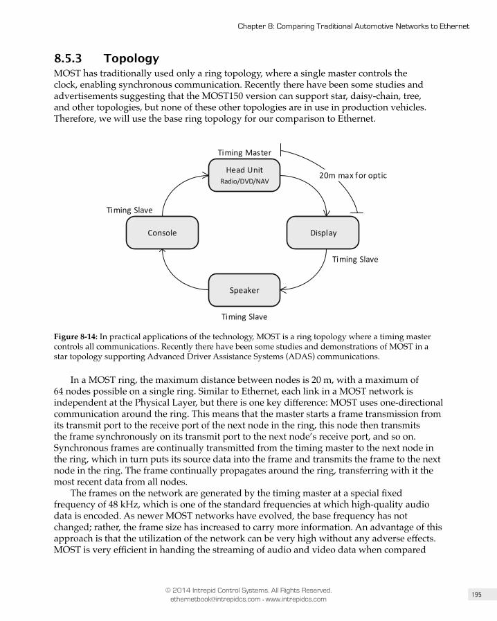
195
Chapter 8: Comparing Traditional Automotive Networks to Ethernet
© 2014 Intrepid Control Systems. All Rights Reserved. [email protected] • www.intrepidcs.com
8.5.3 TopologyMOST has traditionally used only a ring topology, where a single master controls the clock, enabling synchronous communication. Recently there have been some studies and advertisements suggesting that the MOST150 version can support star, daisy-chain, tree, and other topologies, but none of these other topologies are in use in production vehicles. Therefore, we will use the base ring topology for our comparison to Ethernet.
Head UnitRadio/DVD/NAV
DisplayConsole
Speaker
Timing Master
Timing Slave
Timing Slave
Timing Slave
20m max for optic
Figure 8-14: In practical applications of the technology, MOST is a ring topology where a timing master controls all communications. Recently there have been some studies and demonstrations of MOST in a star topology supporting Advanced Driver Assistance Systems (ADAS) communications.
In a MOST ring, the maximum distance between nodes is 20 m, with a maximum of 64 nodes possible on a single ring. Similar to Ethernet, each link in a MOST network is independent at the Physical Layer, but there is one key difference: MOST uses one-directional communication around the ring. This means that the master starts a frame transmission from its transmit port to the receive port of the next node in the ring, this node then transmits the frame synchronously on its transmit port to the next node’s receive port, and so on. Synchronous frames are continually transmitted from the timing master to the next node in the ring, which in turn puts its source data into the frame and transmits the frame to the next node in the ring. The frame continually propagates around the ring, transferring with it the most recent data from all nodes.
The frames on the network are generated by the timing master at a special fixed frequency of 48 kHz, which is one of the standard frequencies at which high-quality audio data is encoded. As newer MOST networks have evolved, the base frequency has not changed; rather, the frame size has increased to carry more information. An advantage of this approach is that the utilization of the network can be very high without any adverse effects. MOST is very efficient in handing the streaming of audio and video data when compared
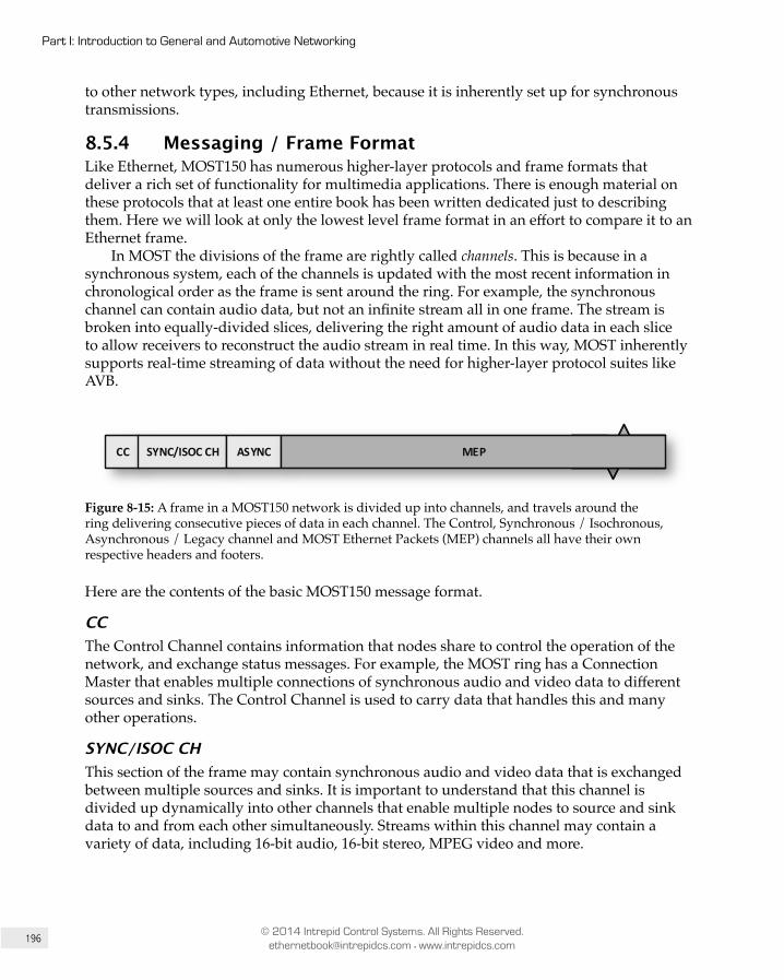
196
Part I: Introduction to General and Automotive Networking
© 2014 Intrepid Control Systems. All Rights Reserved. [email protected] • www.intrepidcs.com
to other network types, including Ethernet, because it is inherently set up for synchronous transmissions.
8.5.4 Messaging / Frame Format Like Ethernet, MOST150 has numerous higher-layer protocols and frame formats that deliver a rich set of functionality for multimedia applications. There is enough material on these protocols that at least one entire book has been written dedicated just to describing them. Here we will look at only the lowest level frame format in an effort to compare it to an Ethernet frame.
In MOST the divisions of the frame are rightly called channels. This is because in a synchronous system, each of the channels is updated with the most recent information in chronological order as the frame is sent around the ring. For example, the synchronous channel can contain audio data, but not an infinite stream all in one frame. The stream is broken into equally-divided slices, delivering the right amount of audio data in each slice to allow receivers to reconstruct the audio stream in real time. In this way, MOST inherently supports real-time streaming of data without the need for higher-layer protocol suites like AVB.
CC SYNC/ISOC CH ASYNC MEP
Figure 8-15: A frame in a MOST150 network is divided up into channels, and travels around the ring delivering consecutive pieces of data in each channel. The Control, Synchronous / Isochronous, Asynchronous / Legacy channel and MOST Ethernet Packets (MEP) channels all have their own respective headers and footers.
Here are the contents of the basic MOST150 message format.
CCThe Control Channel contains information that nodes share to control the operation of the network, and exchange status messages. For example, the MOST ring has a Connection Master that enables multiple connections of synchronous audio and video data to different sources and sinks. The Control Channel is used to carry data that handles this and many other operations.
SYNC/ISOC CHThis section of the frame may contain synchronous audio and video data that is exchanged between multiple sources and sinks. It is important to understand that this channel is divided up dynamically into other channels that enable multiple nodes to source and sink data to and from each other simultaneously. Streams within this channel may contain a variety of data, including 16-bit audio, 16-bit stereo, MPEG video and more.
197
Chapter 8: Comparing Traditional Automotive Networks to Ethernet
© 2014 Intrepid Control Systems. All Rights Reserved. [email protected] • www.intrepidcs.com
ASYNCMOST150 calls this section the Asynchronous/Legacy channel. It is designed to carry event data and packet-based data between the nodes on the ring. It is being replaced by the MEP channel in newer network implementations.
MEPThe MOST Ethernet Packets (MEP) channel is new for MOST150; it is specifically designed to carry Internet Protocol (IP) data, and has a length similar to that of an Ethernet frame. Through the use of this channel, it is possible to provide a fully automotive-compliant network with built in sleep modes and fast wake-up functionality supporting IP-based protocols. This channel can carry up to 120 Mb/s of packet data.
8.5.5 Media Access Control As described earlier, MOST media access control is built on the principle of a bus-timing master that controls the propagation of the MOST frame around the network. Collisions are prevented from occurring because it is a synchronous network based on the general method known as Time Division Multiple Access (TDMA). All nodes on the network share the same clock and must follow strict rules to insert data within the frame to ensure orderly access to the network. At a high level this is similar to FlexRay, in that each node is capable of transmitting in an adjustable time slice within each portion of the frame. Unlike FlexRay, however, these time slices or channels are dynamically adjustable. The frame travels around the network cyclically, carrying with it a slice of data for each channel. The individual slices are then reassembled by the receivers.
8.5.6 Advantages Microchip, the company that owns MOST technology, advertises that one of its largest advantages is that it is the only proven automotive network that supports audio and video streaming, as well as sleep and power management functionally with fast wake up.
MOST is also a standard that includes an entire system approach at the functional level. All necessary layers, protocols and tools to implement a fully functional infotainment system are provided.
Ring topology is arguably less restrictive than the star topology required by a switched Ethernet network.
The fiber optic variant of MOST inherently provides immunity to EMC.
8.5.7 Disadvantages For years, critics of the technology have pointed to one major drawback: it has always been a single-source system, which drives up cost and restricts flexibility. Back in November 2008, The Hansen Report commented:

198
Part I: Introduction to General and Automotive Networking
© 2014 Intrepid Control Systems. All Rights Reserved. [email protected] • www.intrepidcs.com
“Suppliers and car makers think more access to SMSC’s [now Microchip’s] proprietary MOST technology would lower the cost of MOST and increase market acceptance. Some are looking at Ethernet as a possible alternative to MOST.”
The industry has seen some opening up of the standards in response to these concerns, with the MOST150 technology recently being made available to license on a royalty basis. But despite this move, there is only one company that currently supplies silicon for MOST, still keeping it a single-source network with limited options available.
In terms of cost, fiber optic and coaxial cabling are more expensive when compared to UTP. Fiber optic cabling also has the sturdiness and servicing issues that we mentioned earlier.
8.6 Local Interconnect Network (LIN)Unlike all the other networks described here, Local Interconnect Network (LIN) was designed not in response to CAN being too slow, but actually too fast—and too expensive—for certain applications. There are places in even modern vehicles where very low speeds are sufficient, and creating a network significantly slower than CAN allows cost to be reduced even further than the already low price tag on the venerable network, while making implementation easier as well. The result of an effort to move even further in the direction of cheap and simple was the Local Interconnect Network (LIN).
LIN fits niches inside car doors as a network among switches and motors that roll windows up and down; within seat controls; in headliner lighting functionality; in controlling sunroofs; and in other areas that have no need for speed. Since it is on the opposite end of the performance/cost spectrum from Automotive Ethernet, they don’t really compete with each other, and LIN is expected to continue to be popular long into the future regardless of the level of success achieved by AE.
Here are some of the key features of LIN:
• LIN is a single wire network, with a maximum speed of just 20 kb/s, which permits very low-cost and flexible cabling.
• It can be implemented on nearly any microcontroller, even the lowest-cost 8-bit variants. Unlike all other networks explained here, LIN does not require special support in the microcontroller for it to work.
• Its 12V-based Physical Layer means that LIN can be implemented without special transceivers that convert vehicle power to different voltage levels. Transmission of the data stream on the actual medium is as simple as it gets.
8.6.1 BackgroundIn the late 1990s, after the success and wide adoption of CAN, companies such as BMW, Volvo, Audi, Volkswagen and others recognized that networking provided large benefits in reducing wiring harness complexity and weight. CAN, however, was overkill for some
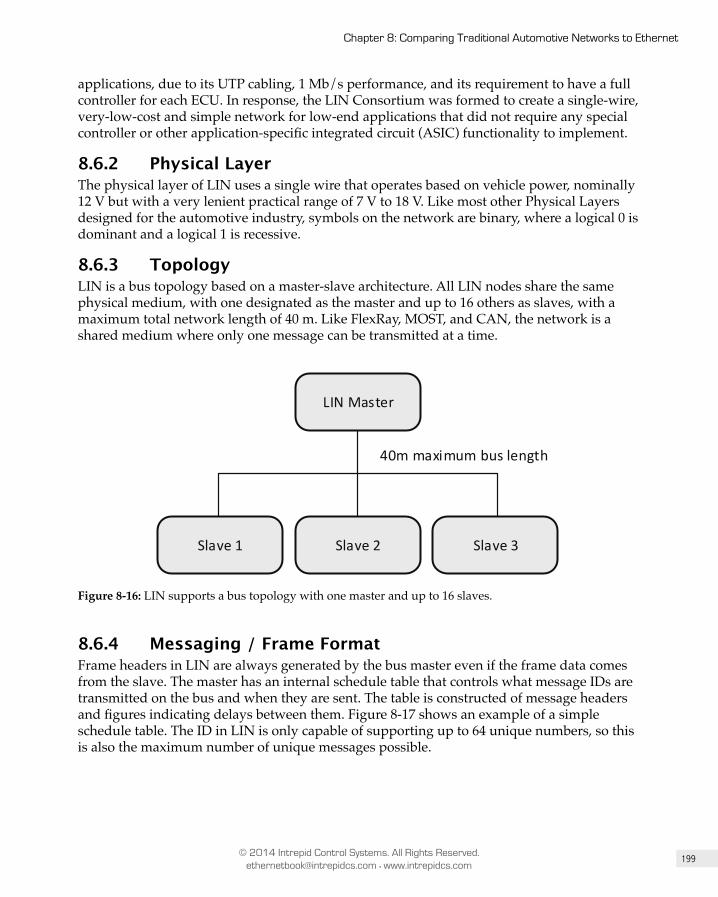
199
Chapter 8: Comparing Traditional Automotive Networks to Ethernet
© 2014 Intrepid Control Systems. All Rights Reserved. [email protected] • www.intrepidcs.com
applications, due to its UTP cabling, 1 Mb/s performance, and its requirement to have a full controller for each ECU. In response, the LIN Consortium was formed to create a single-wire, very-low-cost and simple network for low-end applications that did not require any special controller or other application-specific integrated circuit (ASIC) functionality to implement.
8.6.2 Physical LayerThe physical layer of LIN uses a single wire that operates based on vehicle power, nominally 12 V but with a very lenient practical range of 7 V to 18 V. Like most other Physical Layers designed for the automotive industry, symbols on the network are binary, where a logical 0 is dominant and a logical 1 is recessive.
8.6.3 TopologyLIN is a bus topology based on a master-slave architecture. All LIN nodes share the same physical medium, with one designated as the master and up to 16 others as slaves, with a maximum total network length of 40 m. Like FlexRay, MOST, and CAN, the network is a shared medium where only one message can be transmitted at a time.
LIN Master
Slave 1 Slave 2 Slave 3
40m maximum bus length
Figure 8-16: LIN supports a bus topology with one master and up to 16 slaves.
8.6.4 Messaging / Frame Format Frame headers in LIN are always generated by the bus master even if the frame data comes from the slave. The master has an internal schedule table that controls what message IDs are transmitted on the bus and when they are sent. The table is constructed of message headers and figures indicating delays between them. Figure 8-17 shows an example of a simple schedule table. The ID in LIN is only capable of supporting up to 64 unique numbers, so this is also the maximum number of unique messages possible.
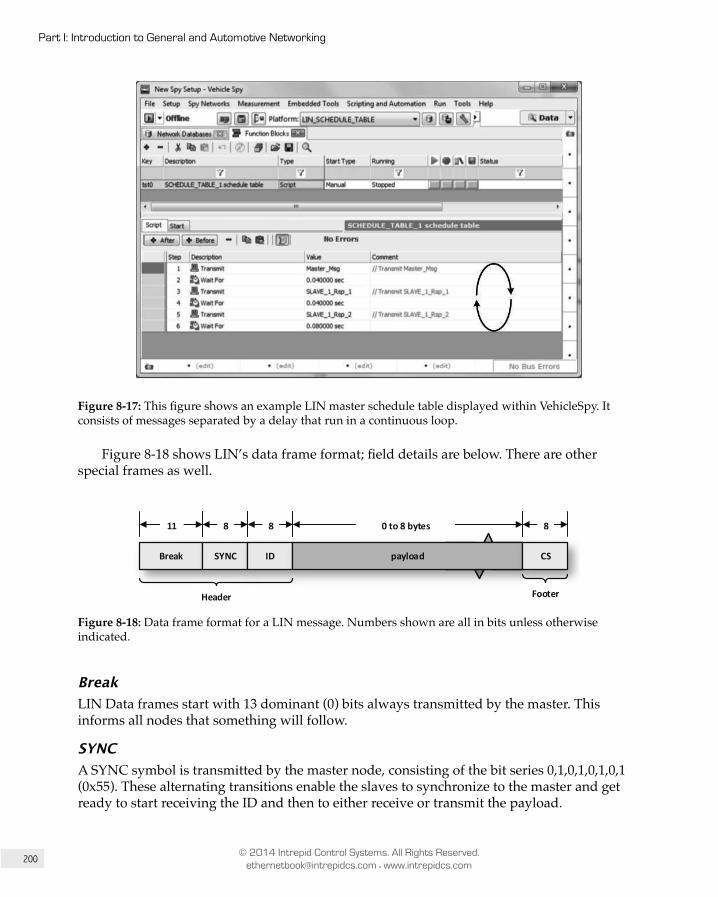
200
Part I: Introduction to General and Automotive Networking
© 2014 Intrepid Control Systems. All Rights Reserved. [email protected] • www.intrepidcs.com
Figure 8-17: This figure shows an example LIN master schedule table displayed within VehicleSpy. It consists of messages separated by a delay that run in a continuous loop.
Figure 8-18 shows LIN’s data frame format; field details are below. There are other special frames as well.
Break SYNC ID payload CS
11 8 8 80 to 8 bytes
Header Footer
Figure 8-18: Data frame format for a LIN message. Numbers shown are all in bits unless otherwise indicated.
BreakLIN Data frames start with 13 dominant (0) bits always transmitted by the master. This informs all nodes that something will follow.
SYNCA SYNC symbol is transmitted by the master node, consisting of the bit series 0,1,0,1,0,1,0,1 (0x55). These alternating transitions enable the slaves to synchronize to the master and get ready to start receiving the ID and then to either receive or transmit the payload.
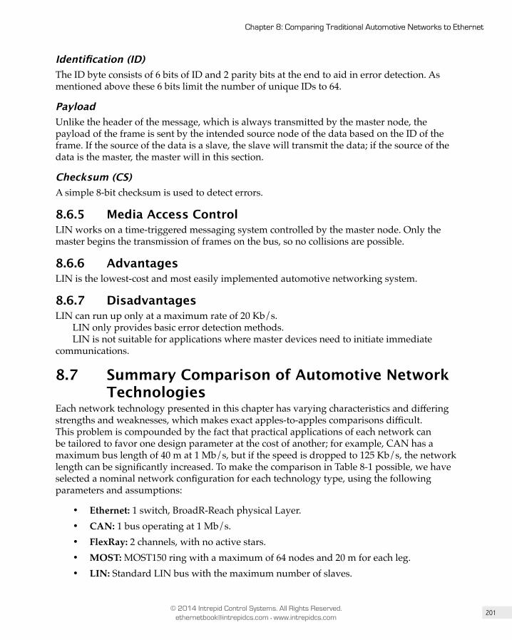
201
Chapter 8: Comparing Traditional Automotive Networks to Ethernet
© 2014 Intrepid Control Systems. All Rights Reserved. [email protected] • www.intrepidcs.com
Identification (ID)The ID byte consists of 6 bits of ID and 2 parity bits at the end to aid in error detection. As mentioned above these 6 bits limit the number of unique IDs to 64.
PayloadUnlike the header of the message, which is always transmitted by the master node, the payload of the frame is sent by the intended source node of the data based on the ID of the frame. If the source of the data is a slave, the slave will transmit the data; if the source of the data is the master, the master will in this section.
Checksum (CS)A simple 8-bit checksum is used to detect errors.
8.6.5 Media Access Control LIN works on a time-triggered messaging system controlled by the master node. Only the master begins the transmission of frames on the bus, so no collisions are possible.
8.6.6 Advantages LIN is the lowest-cost and most easily implemented automotive networking system.
8.6.7 Disadvantages LIN can run up only at a maximum rate of 20 Kb/s.
LIN only provides basic error detection methods.LIN is not suitable for applications where master devices need to initiate immediate
communications.
8.7 Summary Comparison of Automotive Network Technologies
Each network technology presented in this chapter has varying characteristics and differing strengths and weaknesses, which makes exact apples-to-apples comparisons difficult. This problem is compounded by the fact that practical applications of each network can be tailored to favor one design parameter at the cost of another; for example, CAN has a maximum bus length of 40 m at 1 Mb/s, but if the speed is dropped to 125 Kb/s, the network length can be significantly increased. To make the comparison in Table 8-1 possible, we have selected a nominal network configuration for each technology type, using the following parameters and assumptions:
• Ethernet: 1 switch, BroadR-Reach physical Layer.• CAN: 1 bus operating at 1 Mb/s.• FlexRay: 2 channels, with no active stars.• MOST: MOST150 ring with a maximum of 64 nodes and 20 m for each leg.• LIN: Standard LIN bus with the maximum number of slaves.

202
Part I: Introduction to General and Automotive Networking
© 2014 Intrepid Control Systems. All Rights Reserved. [email protected] • www.intrepidcs.com
Ethernet CAN FlexRay MOST LIN
Maximum Bandwidth (Mb/s) 100 per link, full-duplex 1 20 150 0.02
Maximum Number of Nodes
Limited only by the number of switch ports 30 22 64 16
Network Length 15 m per link 40 m 24 m 1280 m 40 m
Messaging Frames Cyclic frames Cyclic frames Cyclic frames / streams
Cyclic frames
Media Access Control Full-duplex, contentionless
Non- destructive arbitration
Time- triggered
Time- triggered
Time- triggered
Cost High Low Low High Very low
Topologies Star, tree Bus Bus, star, hybrid Ring, star Bus
Power Management / Sleep Modes Yes Yes Yes Yes Yes
Standardization OPEN Alliance, Future IEEE 802.3 ISO 11898 FlexRay
Consortium
Originally proprietary, recently opened by MOST Cooperation
ISO 17987
Safety-critical functionality
Proven outside of automotive applications
Yes Yes No No
Availability Multiple vendors and growing Many Few One Many
System-on-Chip Many Many Few None Many
Cabling UTP UTP UTPOptical (MOST150), UTP (MOST50)
1-wire
Error Detection Strong Strong Strong Strong Weak
Error CorrectionNone (relies on higher-layer protocols)
Re-transmit NoneNone (relies on higher-layer protocols)
None
Main ApplicationsInfotainment (now), Backbone and safety (future)
General bus Safety-critical, x-by-wire Infotainment
Switches, doors, seats
Table 8-1: A comparison of some of the important characteristics of different automotive networks that we’ve discussed in this chapter.

203
Chapter 8: Comparing Traditional Automotive Networks to Ethernet
© 2014 Intrepid Control Systems. All Rights Reserved. [email protected] • www.intrepidcs.com
As we explained right at the start of the book in Chapter 1, it is our belief that Automotive Ethernet is already “too big to fail”. The advantages of Ethernet match up well with the future needs of automobiles, and it has proven to be flexible and robust for numerous safety-critical applications in other fields, such as aerospace. As adoption of AE spreads, more companies will hop on the bandwagon and options will increase, while costs will go down. While other networks will continue to play a role in the car of the future, AE will be a major player as well.
LIN CAN
FlexRay
MOST
1 2 5 10
Relative cost per node
Dat
a ra
te [
bps]
20K
1M
10M
25M
CAN-FD
Ethernet 100Mb
50M
150M
100M
non-
linea
r
Figure 8-19: Relative cost and aggregate data rate/bandwidth of the main automotive networks.
PART III
TCP/IP Network Layer (OSI Layer 3) Protocols

Chapter
Overview of the TCP/IP Protocol Suite and ArchitectureBy Charles M. Kozierok. This material was largely adapted from the electronic version of The TCP/IP Guide at tcpipguide.com, and will be updated in a future book edition to reflect recent changes to TCP/IP.
13.1 IntroductionJust as Ethernet rules the roost when it comes to local networking, modern internetworking is dominated by the suite known as TCP/IP. Named for two key protocols of the many that comprise it, TCP/IP has been in continual development and use for about four decades. In that time, it has evolved from an experimental technology used to hook together a handful of research computers, to the powerhouse of the largest and most complex computer system in history: the global Internet, connecting together millions of networks and end devices.
This chapter provides a brief introduction of the TCP/IP protocol suite, including an overview and history of its technologies and explanation of its general design and architecture, and a list of some of its most important protocols. Note that a number of protocols are mentioned here for the sake of providing a full “big picture” look at the TCP/IP world; not all of these are covered in this book, where our focus, at least for now, is mainly on explaining the core TCP/IP layer 3 and layer 4 protocols most relevant Automotive Ethernet.
13
430
Part III: TCP/IP Network Layer (OSI Layer 3) Protocols
© 2014 Intrepid Control Systems. All Rights Reserved. [email protected] • www.intrepidcs.com
13.2 TCP/IP Overview and HistoryThe best place to start looking at TCP/IP is probably the name itself. TCP/IP in fact consists of dozens of different protocols, but only a few are the “main” protocols that define the core operation of the suite. Of these key protocols, two are usually considered the most important. The Internet Protocol (IP) is the primary OSI Network Layer (layer 3) protocol that provides addressing, datagram routing and other functions in an internetwork. The Transmission Control Protocol (TCP) is the primary transport layer (layer 4) protocol, and is responsible for connection establishment and management and reliable data transport between software processes on devices.
Due to the importance of these two protocols, their abbreviations have come to represent the entire suite: “TCP/IP”. (In a moment we’ll discover the actual history of that name.) IP and TCP are essential because many of TCP/IP’s most critical functions are implemented at layers 3 and 4. However, there is much more to TCP/IP than just TCP and IP. The protocol suite as a whole requires the work of many different protocols and technologies to provide users with the applications they need.
TCP/IP employs its own four-layer architecture that corresponds roughly to the OSI Reference Model and provides a framework for the various protocols that comprise the suite. It also includes numerous high-level applications, some of which are well-known by Internet users who may not realize they are part of TCP/IP, such as the Hypertext Transfer Protocol (HTTP), which runs the World Wide Web.
Early TCP/IP History The Internet and TCP/IP are so closely related in their history that it is difficult to discuss one without also talking about the other—they were developed together, with TCP/IP providing the mechanism for implementing what became the Internet. TCP/IP has over the years continued to evolve to meet the needs of Internet users and operators. We will provide a brief summary of the history of TCP/IP here; of course, whole books have been written on TCP/IP and Internet history, so this is just a quick look for sake of context.
The TCP/IP protocols were initially developed as part of the research network developed by the United States Defense Advanced Research Projects Agency (DARPA or ARPA). Initially, this fledgling network, called the ARPAnet, was designed to use a number of protocols that had been adapted from existing technologies. However, they all had flaws or limitations, either in conceptual design or in practical matters such as capacity, when used on the ARPAnet. The developers of the new network recognized that trying to use these existing protocols might eventually lead to problems as ARPAnet scaled to a larger size and was adapted for newer uses and applications.
In 1973, development of a full-fledged system of internetworking protocols for the ARPAnet began. What many people don’t realize is that in early versions of this technology, there was only one core protocol: TCP. And in fact, these letters didn’t even mean what they do today; they stood for the Transmission Control Program. The first version of this prede cessor of modern TCP was written in 1973, then revised and formally documented in RFC 675, Specification of Internet Transmission Control Program, December 1974.

431
Chapter 13: Overview of the TCP/IP Protocol Suite and Architecture
© 2014 Intrepid Control Systems. All Rights Reserved. [email protected] • www.intrepidcs.com
Note: Internet standards are defined in documents called Requests For Comments (RFCs). These documents, and the process used to
create them, are overviewed in Chapter 6.
Modern TCP/IP Development and the Creation of TCP/IP Architecture Testing and development of TCP continued for several years. In March 1977, version 2 of TCP was documented, and in August 1977, a significant turning point came in TCP/IP’s devel opment. Jon Postel, one of the most important pioneers of the Internet and TCP/IP, published a set of comments on the state of TCP. In that document (known as Internet Engineering Note number 2, or IEN 2), he provided superb evidence that architectural models and protocol layers aren’t just for textbooks:
“We are screwing up in our design of internet protocols by violating the principle of layering. Specifically we are trying to use TCP to do two things: serve as a host level end to end protocol, and to serve as an internet packaging and routing protocol. These two things should be provided in a layered and modular way. I suggest that a new distinct internetwork protocol is needed, and that TCP be used strictly as a host level end to end protocol.”
– Jon Postel, IEN 2, 1977
What Postel was essentially saying was that the version of TCP created in the mid-1970s was trying to do too much; specifically, it was encompassing both layer 3 and layer 4 activities. His vision was prophetic, because we now know that having TCP handle all of these activities would have indeed led to problems down the road.
Postel’s observation led to the splitting of TCP into TCP at the Transport Layer and IP at the Network Layer—thus the name “TCP/IP”—and the creation of TCP/IP architecture. The process of dividing TCP into two portions began in version 3 of TCP, written in 1978. The first formal standards for the versions of IP and TCP used in modern networks (version 4) were created in 1980. This is why the first “real” version of IP is version 4 and not version 1.

432
Part III: TCP/IP Network Layer (OSI Layer 3) Protocols
© 2014 Intrepid Control Systems. All Rights Reserved. [email protected] • www.intrepidcs.com
Key Information: TCP/IP was initially developed in the 1970s as part of an effort to define a set of technologies to operate the
fledgling Internet. The name “TCP/IP” came about when the original Transmission Control Program (TCP) was split into the Transmission Control Protocol (TCP) and Internet Protocol (IP). The first modern versions of these two key protocols were documented in 1980 as TCP version 4 and IP version 4.
Important Factors in the Success of TCP/IPIn its early years, TCP/IP was just “one of many” different sets of protocols that could be used to provide Network Layer and Transport Layer functionality. Today it is such a dominant force that other options are largely unknown. TCP/IP’s rise in popularity is due in part to historical factors, such as described above, but also to several essential characteristics of the protocol suite itself:
• Integrated Addressing System: TCP/IP includes within it a system for identifying and addressing devices on both small and large networks. It allows devices to be addressed regardless of the lower-level details of how each constituent network is constructed. The addressing system also includes a centralized administration capability to ensure that each device has a unique address.
• Design For Routing: Unlike some network-layer protocols, TCP/IP is specifically designed to facilitate the routing of information over an internetwork of arbitrary complexity. In fact, TCP/IP is conceptually concerned more with the connection of networks, than with the connection of devices. A number of support protocols are also included in TCP/IP to allow networks to exchange critical information and manage the efficient flow of information from one to another.
• Underlying Network Independence: TCP/IP operates primarily at layers 3 and above, and includes provisions to allow it to function on LANs, wireless LANs and WANs of various sorts. This flexibility means that one can mix and match a variety of different underlying networks and connect them all using TCP/IP.
• Scalability: One of the most amazing characteristics of TCP/IP is how scalable its protocols have proven to be as the Internet has grown from a small network with just a few machines to a huge internetwork with hundreds of millions of hosts. While some changes have been required periodically to support this growth, the core of TCP/IP is basically the same as it was in the 1980s.
• Open Standards and Development Process: The TCP/IP standards are not propri-etary, but rather open standards freely available to the public. Furthermore, the process used to develop them is also completely open—they are created and modified using the democratic RFC process, which allows all input to be considered and helps ensures the world-wide acceptance of what is developed.
433
Chapter 13: Overview of the TCP/IP Protocol Suite and Architecture
© 2014 Intrepid Control Systems. All Rights Reserved. [email protected] • www.intrepidcs.com
• Universality: Everyone uses TCP/IP because everyone uses it!
This last point sounds like a Yogi Berra quip, but is arguably the most important. Not only is TCP/IP the “underlying language of the Internet”, it is also used in most private networks today. Even former “competitors” to TCP/IP such as NetWare now use TCP/IP to carry traffic. It is likely that TCP/IP will remain a big part of internetworking for the foreseeable future, even expanding its scope. Of course, its increasing use in vehicles with Automotive Ethernet is an excellent example of this phenomenon.
Key Information: While TCP/IP is not the only internetworking protocol suite, it is definitely the most important one. Its unparalleled
success is due to historical factors and technical advantages, as well as its open standards and development process.
13.3 TCP/IP Services and Client/Server OperationTCP/IP is most often studied in terms of its layer-based architecture and the protocols that it provides at those different layers. These protocols, however, represent the technical details of how TCP/IP works. They are of interest to us as students of technology, but are normally hidden from users who do not need to see the “guts” of how TCP/IP works to know that it does. Before proceeding to these details, it’s instructive to take a “bigger picture” look at what TCP/IP does.
TCP/IP Services In Chapter 7 we mentioned that the theoretical operation of the OSI model is based on the concept of one layer providing services to the layers above it. TCP/IP covers many layers of the OSI model, and so it collectively provides services of this sort as well in many ways. Conceptually, we can divide TCP/IP services into two groups: services provided to other protocols, and services provided to end users.
Services Provided to Other ProtocolsThe first group of services consists of the core functions implemented by the main TCP/IP protocols such as IP, TCP and UDP. These services are designed to actually accomplish the internetworking functions of the protocol suite. For example, at the Network Layer, IP provides functions such as addressing, delivery, and datagram packaging, fragmentation and reassembly. At the Transport Layer, TCP and UDP are concerned with encapsulating user data and managing connections between devices. Other protocols provide routing and management functionality.
End-User ServicesThese facil itate the operation of the applications that users run to exploit the power of the Internet and other TCP/IP systems. For example, the World Wide Web (WWW) is arguably the
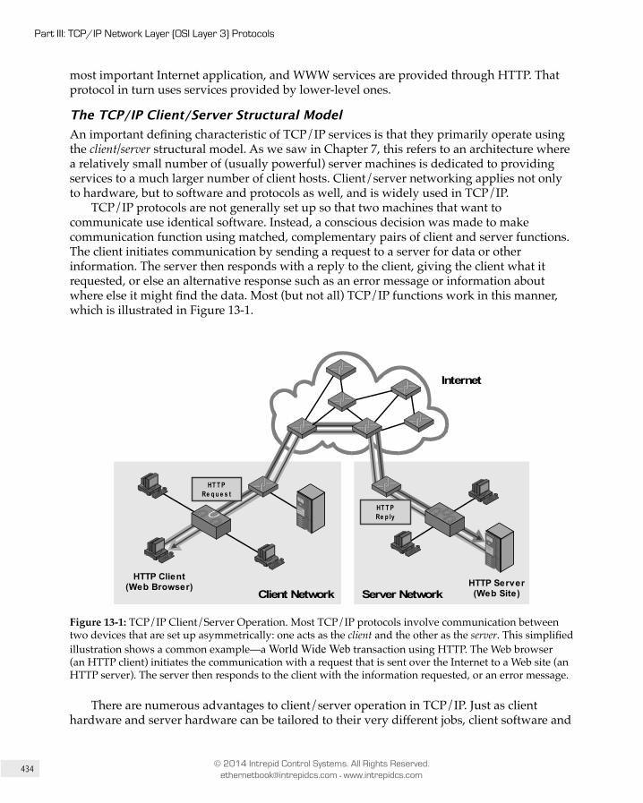
434
Part III: TCP/IP Network Layer (OSI Layer 3) Protocols
© 2014 Intrepid Control Systems. All Rights Reserved. [email protected] • www.intrepidcs.com
most important Internet application, and WWW services are provided through HTTP. That protocol in turn uses services provided by lower-level ones.
The TCP/IP Client/Server Structural Model An important defining characteristic of TCP/IP services is that they primarily operate using the client/server structural model. As we saw in Chapter 7, this refers to an architecture where a relatively small number of (usually powerful) server machines is dedicated to providing services to a much larger number of client hosts. Client/server networking applies not only to hardware, but to software and protocols as well, and is widely used in TCP/IP.
TCP/IP protocols are not generally set up so that two machines that want to communicate use identical software. Instead, a conscious decision was made to make communication function using matched, complementary pairs of client and server functions. The client initiates communication by sending a request to a server for data or other information. The server then responds with a reply to the client, giving the client what it requested, or else an alternative response such as an error message or information about where else it might find the data. Most (but not all) TCP/IP functions work in this manner, which is illustrated in Figure 13-1.
Client NetworkHTTP Client
(Web Browser)
HT T PRe q u e s t
HTTP Server(Web Site)
HT T PRe p ly
Internet
Server Network
Figure 13-1: TCP/IP Client/Server Operation. Most TCP/IP protocols involve communication between two devices that are set up asymmetrically: one acts as the client and the other as the server. This simplified illustration shows a common example—a World Wide Web transaction using HTTP. The Web browser (an HTTP client) initiates the communication with a request that is sent over the Internet to a Web site (an HTTP server). The server then responds to the client with the information requested, or an error message.
There are numerous advantages to client/server operation in TCP/IP. Just as client hardware and server hardware can be tailored to their very different jobs, client software and

435
Chapter 13: Overview of the TCP/IP Protocol Suite and Architecture
© 2014 Intrepid Control Systems. All Rights Reserved. [email protected] • www.intrepidcs.com
the server software can also be optimized to do their work as efficiently as possible. Let’s take again the Web as another example. A Web browser is created to provide the interface to the user and to talk to Web servers; the Web server software is very different, generally consisting only of high-powered software services that receive and respond quickly to many requests simultaneously with no user interaction at all.
Key Information: The TCP/IP protocol suite is strongly oriented around the notion of client/server network communication.
Clients normally initiate communications by sending requests, and servers respond to such requests. Both clients and servers can be optimized for their intended functions.
Understanding TCP/IP Client and Server Roles The terms “client” and “server” can be confusing in TCP/IP because they are used in several different ways, sometimes simultaneously:
• Hardware Roles: The terms “client” and “server” usually refer to the primary roles played by networked hardware. A “client” computer is usually something like a PC, Apple computer or mobile device used by an individual, and primarily initiates conversations by sending requests. A “server” is usually a very high-powered machine dedicated to responding to client requests, sitting in a data center somewhere that nobody but its administrator ever sees.
• Software Roles: As mentioned earlier, TCP/IP uses different pieces of software for many protocols to implement “client” and “server” roles. Client software is usually found on client hardware and server software on server hardware, but not always—some devices may run both.
• Transactional Roles: In any specific exchange of information, the client is normally the device that initiates communication or sends a query; the server responds, usually providing information. Again, most often client software on a client device initiates the trans action, but not always.
In a typical organization there will be many smaller individual computers designated “clients”, and a few larger ones that are “servers”. The servers normally run server software, and the clients run client software. But servers can also be set up with client software, and clients with server software.
For example, suppose you are an administrator working in the computer room on server #1 and need to transfer a file to server #2. You fire up the File Transfer Protocol (FTP) to initiate a session with server #2. In this transaction, server #1 is playing the role of the client, since it is initiating communication using an FTP client program, while server #2 is playing the server role. Theoretically, you could even start an FTP transfer from server #1 to a
436
Part III: TCP/IP Network Layer (OSI Layer 3) Protocols
© 2014 Intrepid Control Systems. All Rights Reserved. [email protected] • www.intrepidcs.com
particular client, if that client had FTP server software to answer the server’s request. (This is less common, because server software is often not installed on client machines.)
Transactional roles come into play when communication occurs between servers in certain protocols. For example, when two Simple Mail Transfer Protocol (SMTP) servers communicate to exchange electronic mail, during any trans action one device acts as the client while the other acts as the server, even though they are both server programs running on server hardware. In some situations, devices can even swap client and server roles in the middle of a transaction!
Client and server roles tend to evolve over time. In the 1990s, the increasing power of personal computers with “always-on” broadband connectivity led to a significant blurring of client and server hardware and software, as well as more use of the peer-to-peer model for applications such as file sharing. In the late 2000s and early 2010s, however, the trend has reversed, led primarily by an explosion in the use of mobile devices; these are generally limited in capability and thus more reliant on servers to provide functionality, making client/server more important than ever. Other trends, such as cloud computing, are also further reinforcing the idea of centralizing capability on servers and accessing them with “lightweight” clients.
Key Information: Understanding client/server computing concepts in TCP/IP is made more complex due to the very different
meanings that the terms “client” and “server” can have in various contexts. The two terms can refer to hardware roles—designa tions given to hardware devices based on whether they usually function as clients or as servers. The terms can also refer to software roles, meaning whether protocol software components function as clients or servers. Finally, they can refer to transactional roles, meaning whether a device and program functions as a client or server in any given exchange of data.
13.4 TCP/IP Architecture and the TCP/IP (DARPA/DOD) Model
The OSI Reference Model, which we examined in detail in Chapter 7, consists of seven layers that split the tasks required to implement a network. It’s the main conceptual tool used to describe networking, but is not the only way that tasks are divided into layers and components. The TCP/IP protocol suite was in fact created before the OSI Reference Model, and as such, its inventors used their own model to describe it. Fortunately, as we’ll see, this model is more like the OSI model than different from it.
The TCP/IP Model The model created by TCP/IP’s developers goes by different names, including the TCP/IP model, the DARPA model (after the agency that was largely responsible for devel oping TCP/IP via the ARPAnet described earlier) and the DOD model (after the United States Department
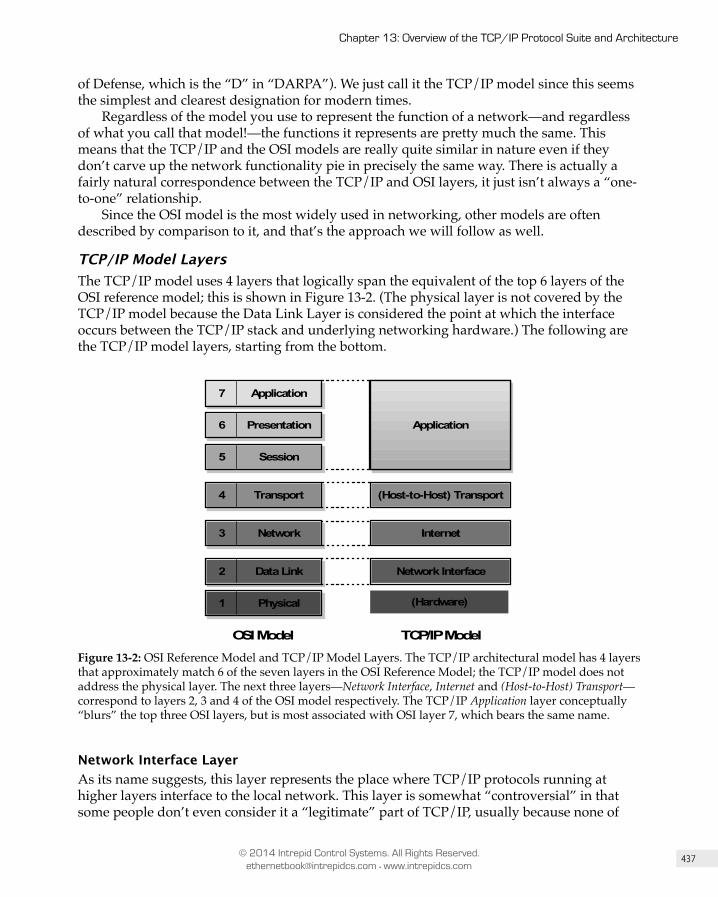
437
Chapter 13: Overview of the TCP/IP Protocol Suite and Architecture
© 2014 Intrepid Control Systems. All Rights Reserved. [email protected] • www.intrepidcs.com
of Defense, which is the “D” in “DARPA”). We just call it the TCP/IP model since this seems the simplest and clearest designation for modern times.
Regardless of the model you use to represent the function of a network—and regardless of what you call that model!—the functions it represents are pretty much the same. This means that the TCP/IP and the OSI models are really quite similar in nature even if they don’t carve up the network functionality pie in precisely the same way. There is actually a fairly natural correspondence between the TCP/IP and OSI layers, it just isn’t always a “one-to-one” relationship.
Since the OSI model is the most widely used in networking, other models are often described by comparison to it, and that’s the approach we will follow as well.
TCP/IP Model Layers The TCP/IP model uses 4 layers that logically span the equivalent of the top 6 layers of the OSI reference model; this is shown in Figure 13-2. (The physical layer is not covered by the TCP/IP model because the Data Link Layer is considered the point at which the interface occurs between the TCP/IP stack and underlying networking hardware.) The following are the TCP/IP model layers, starting from the bottom.
OSI Model TCP/IP Model
Application
7 Application
1 Physical
6 Presentation
5 Session
4 Transport
3 Network
2 Data Link
Application
(Host-to-Host) Transport
Internet
Network Interface
(Hardware)
Figure 13-2: OSI Reference Model and TCP/IP Model Layers. The TCP/IP architectural model has 4 layers that approximately match 6 of the seven layers in the OSI Reference Model; the TCP/IP model does not address the physical layer. The next three layers—Network Interface, Internet and (Host-to-Host) Transport—correspond to layers 2, 3 and 4 of the OSI model respectively. The TCP/IP Application layer conceptually “blurs” the top three OSI layers, but is most associated with OSI layer 7, which bears the same name.
Network Interface LayerAs its name suggests, this layer represents the place where TCP/IP protocols running at higher layers interface to the local network. This layer is somewhat “contro versial” in that some people don’t even consider it a “legitimate” part of TCP/IP, usually because none of

438
Part III: TCP/IP Network Layer (OSI Layer 3) Protocols
© 2014 Intrepid Control Systems. All Rights Reserved. [email protected] • www.intrepidcs.com
the core IP protocols run here, but it is definitely part of the architecture. It is equivalent to the Data Link Layer (layer 2) in the OSI Reference Model and is occasionally called the Link Layer; the name Network Access Layer is also sometimes seen.
On many TCP/IP networks, there is no TCP/IP protocol running at all on this layer, because it is simply not needed. For example, if you run TCP/IP over an Ethernet, then Ethernet handles layer 2 (and layer 1) functions, and the interface between Ethernet and TCP/IP is accomplished through Ethernet drivers. However, the TCP/IP standards do define protocols for TCP/IP networks that do not have their own layer two implementation. One well-known TCP/IP Network Interface Layer protocol is the Point-to-Point Protocol (PPP), which has been used for many years to implement several methods of Internet access.
Internet LayerThis layer corresponds to the Network Layer in the OSI Reference Model, and for that reason is sometimes called the Network Layer even in TCP/IP model discussions. It is responsible for typical layer 3 jobs, such as logical device addressing, data packaging, manipulation and delivery, and last but not least, routing. At this layer we find the Internet Protocol (IP)—arguably the heart of TCP/IP—support protocols such as ICMP, and also the suite’s routing protocols (RIP, OSFP, BGP, etc.) The new version of IP, called IP version 6, will be used for the Internet of the future and is of course also found here.
(Host-to-Host) Transport LayerThis primary job of this layer is to facilitate end-to-end communication over an internetwork. It is in charge of allowing logical connections to be made between devices to allow data to be sent either unreliably (with no guarantee that it gets there) or reliably (where the protocol keeps track of the data sent and received to make sure it arrives). It is also here that identification of specific source and destination appli cation processes is accomplished.
The key TCP/IP protocols at this layer are the Transmission Control Protocol (TCP) and User Datagram Protocol (UDP). The formal name of this layer is often shortened to just the Transport Layer; which is of course the same name as the layer of the OSI model which it most closely corresponds. However, the TCP/IP Transport Layer protocol includes certain elements that are arguably part of the OSI Session Layer. For example, TCP establishes a connection that can persist for a long period of time, which some people (controversially) say makes TCP actually straddle layers 4 and 5.
Application LayerThe highest layer in the TCP/IP model is a rather broad one, encompassing layers 5 through 7 in the OSI model. While this seems to represent a loss of detail compared to the OSI model, that’s actually a good thing—the TCP/IP model better reflects the “blurry” nature of the divisions between the functions of the higher layers in the OSI model, which often seem rather arbitrary.
Numerous protocols reside at the Application Layer. These include application protocols such as HTTP, FTP and SMTP for providing end-user services, as well as administrative protocols like the Simple Network Management Protocol (SNMP) and Dynamic Host Configuration Protocol (DHCP).

439
Chapter 13: Overview of the TCP/IP Protocol Suite and Architecture
© 2014 Intrepid Control Systems. All Rights Reserved. [email protected] • www.intrepidcs.com
Key Information: The architecture of the TCP/IP protocol suite is often described in terms of a layered reference model called
the TCP/IP model, DARPA model or DOD model. It includes four layers: the Network Interface Layer (respon sible for interfacing the suite to the physical hardware on which it runs), the Internet Layer (where device addressing, basic datagram communication and routing take place), the Host-to-Host Transport Layer (where connections are managed and reliable communication is ensured) and the Application Layer (where end-user applications and services are implemented.) The first three layers correspond roughly to layers 2 through 4 of the OSI Reference Model respectively; the last is equivalent to OSI layers 5 to 7.
13.5 Summary of Key TCP/IP ProtocolsSince TCP/IP is a protocol suite, it is most often discussed in terms of the protocols that comprise it. Each protocol “resides” in a particular layer of the TCP/IP architectural model we saw earlier in the chapter, though only to a certain extent. The developers of TCP/IP protocols are cognizant of the importance of layers, but are not strict about their use. Protocol standards respect the important benefits of layering, such as modularity, but also understand the essential rule that layers should only be used when they make sense, and are careful not to put this particular proverbial cart before the horse.
There are a few TCP/IP protocols that are usually called the “core” of the suite, because they are responsible for its basic operation. Which protocols belong in this category is a matter of some conjecture, but most people would definitely include here the main protocols at the Internet and Transport Layers: the Internet Protocol (IP), Transmission Control Protocol (TCP) and User Datagram Protocol (UDP).
There are many hundreds of TCP/IP protocols and applications in total, and it is mainly the core ones that are covered in this book. But to give you an idea of what some of the other important ones are, we’ve included below a number of tables that provide a summary of essential protocols found at the various layers. The organization of protocols in the TCP/IP suite can also be seen at a glance in Figure 13-3.
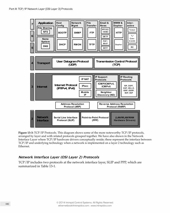
440
Part III: TCP/IP Network Layer (OSI Layer 3) Protocols
© 2014 Intrepid Control Systems. All Rights Reserved. [email protected] • www.intrepidcs.com
Application
Transport
Internet
Network Interface
7
6
5
4
3
2 Serial Line InterfaceProtocol (SLIP)
Point-to-Point Protocol(PPP)
Address ResolutionProtocol (ARP)
Reverse Address ResolutionProtocol (RARP)
IPsec
MobileIP
Transmission Control Protocol(TCP)
User Datagram Protocol(UDP)
NameSystem
DNS
File SharingNFS
HostConfig
DHCP
BOOTP
NetworkMgmt
RMON
SNMP
FileTransfer
TFTP
FTP
Email &News
RFC 822/ M IM E
SM T P
NNT P
WWW &Gopher
Go p h e r
HTTP
Inter-active
T e ln e t
"r "C o m -
m an d s
Application
POP /IM A P
IP NAT
Internet Protocol(IP/IPv4, IPv6)
IP SupportProtocols
ICMP/ICMPv4,ICMPv6
NeighborDiscovery (ND)
IP RoutingProtocols
RIP, OSPF,GGP, HEL L O,IGRP, EIGRP,
BGP, EGP
(LAN/WLAN/WANHardware Drivers)
IRC
Figure 13-3: TCP/IP Protocols. This diagram shows some of the more noteworthy TCP/IP protocols, arranged by layer and with related protocols grouped together. We have also shown in the Network Interface Layer where TCP/IP hardware drivers conceptually reside; these represent the interface between TCP/IP and underlying technology when a network is implemented on a layer 2 technology such as Ethernet.
Network Interface Layer (OSI Layer 2) ProtocolsTCP/IP includes two protocols at the network interface layer, SLIP and PPP, which are summarized in Table 13-1.
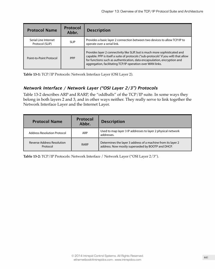
441
Chapter 13: Overview of the TCP/IP Protocol Suite and Architecture
© 2014 Intrepid Control Systems. All Rights Reserved. [email protected] • www.intrepidcs.com
Protocol Name Protocol Abbr. Description
Serial Line Internet Protocol (SLIP) SLIP Provides a basic layer 2 connection between two devices to allow TCP/IP to
operate over a serial link.
Point-to-Point Protocol PPP
Provides layer 2 connectivity like SLIP, but is much more sophisticated and capable. PPP is itself a suite of protocols (“sub-protocols” if you will) that allow for functions such as authentication, data encapsulation, encryption and aggregation, facilitating TCP/IP operation over WAN links.
Table 13-1: TCP/IP Protocols: Network Interface Layer (OSI Layer 2).
Network Interface / Network Layer (“OSI Layer 2/3”) Protocols Table 13-2 describes ARP and RARP, the “oddballs” of the TCP/IP suite. In some ways they belong in both layers 2 and 3, and in other ways neither. They really serve to link together the Network Interface Layer and the Internet Layer.
Protocol Name Protocol Abbr. Description
Address Resolution Protocol ARP Used to map layer 3 IP addresses to layer 2 physical network addresses.
Reverse Address Resolution Protocol RARP Determines the layer 3 address of a machine from its layer 2
address. Now mostly superseded by BOOTP and DHCP.
Table 13-2: TCP/IP Protocols: Network Interface / Network Layer (“OSI Layer 2/3”).
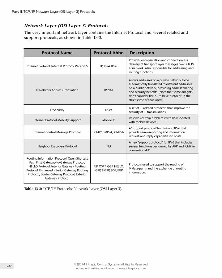
442
Part III: TCP/IP Network Layer (OSI Layer 3) Protocols
© 2014 Intrepid Control Systems. All Rights Reserved. [email protected] • www.intrepidcs.com
Network Layer (OSI Layer 3) Protocols The very important network layer contains the Internet Protocol and several related and support protocols, as shown in Table 13-3.
Protocol Name Protocol Abbr. Description
Internet Protocol, Internet Protocol Version 6 IP, Ipv4, IPv6
Provides encapsulation and connectionless delivery of transport layer messages over a TCP/IP network. Also responsible for addressing and routing functions.
IP Network Address Translation IP NAT
Allows addresses on a private network to be automati cally translated to different addresses on a public network, providing address sharing and security benefits. (Note that some analysts don’t consider IP NAT to be a “protocol” in the strict sense of that word.)
IP Security IPSec A set of IP-related protocols that improve the security of IP transmissions.
Internet Protocol Mobility Support Mobile IP Resolves certain problems with IP associated with mobile devices.
Internet Control Message Protocol ICMP/ICMPv4, ICMPv6A “support protocol” for IPv4 and IPv6 that provides error-reporting and information request-and-reply capabilities to hosts.
Neighbor Discovery Protocol NDA new “support protocol” for IPv6 that includes several functions performed by ARP and ICMP in conventional IP.
Routing Information Protocol, Open Shortest Path First, Gateway-to-Gateway Protocol, HELLO Protocol, Interior Gateway Routing
Protocol, Enhanced Interior Gateway Routing Protocol, Border Gateway Protocol, Exterior
Gateway Protocol
RIP, OSPF, GGP, HELLO, IGRP, EIGRP, BGP, EGP
Protocols used to support the routing of IP datagrams and the exchange of routing information.
Table 13-3: TCP/IP Protocols: Network Layer (OSI Layer 3).
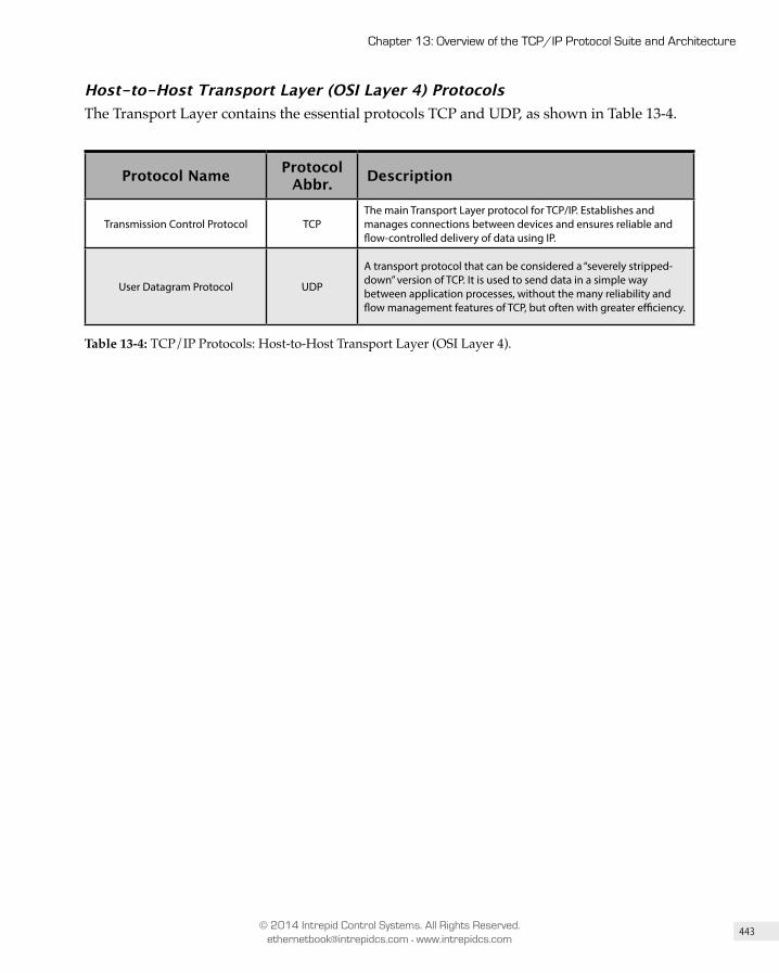
443
Chapter 13: Overview of the TCP/IP Protocol Suite and Architecture
© 2014 Intrepid Control Systems. All Rights Reserved. [email protected] • www.intrepidcs.com
Host-to-Host Transport Layer (OSI Layer 4) Protocols The Transport Layer contains the essential protocols TCP and UDP, as shown in Table 13-4.
Protocol Name Protocol Abbr. Description
Transmission Control Protocol TCPThe main Transport Layer protocol for TCP/IP. Establishes and manages connections between devices and ensures reliable and flow-controlled delivery of data using IP.
User Datagram Protocol UDP
A transport protocol that can be considered a “severely stripped-down” version of TCP. It is used to send data in a simple way between application processes, without the many reliability and flow management features of TCP, but often with greater efficiency.
Table 13-4: TCP/IP Protocols: Host-to-Host Transport Layer (OSI Layer 4).

444
Part III: TCP/IP Network Layer (OSI Layer 3) Protocols
© 2014 Intrepid Control Systems. All Rights Reserved. [email protected] • www.intrepidcs.com
Application Layer (OSI Layer 5/6/7) Protocols As mentioned earlier, in TCP/IP the single Application Layer covers the equivalent of OSI layers 5, 6 and 7. Some of the application protocols are shown in Table 13-5.
Protocol Name Protocol Abbr. Description
Domain Name System DNSProvides the ability to refer to IP devices using names instead of just numerical IP addresses. Allows machines to resolve these names into their corresponding IP addresses.
Network File System NFS Allows files to be shared seamlessly across TCP/IP networks.
Bootstrap Protocol BOOTPDeveloped to address some of the issues with RARP and used in a similar manner: to allow the configuration of a TCP/IP device at startup. Generally superseded by DHCP.
Dynamic Host Configuration Protocol DHCP
A complete protocol for configuring TCP/IP devices and managing IP addresses. The successor to RARP and BOOTP, it includes numer-ous features and capabilities and is widely used for automatic IP address assignment.
Simple Network Management Protocol SNMP A full-featured protocol for remote management of networks and
devices.
Remote Monitoring RMON A diagnostic “protocol” (really a part of SNMP) used for remote monitoring of network devices.
File Transfer Protocol, Trivial File Transfer Protocol FTP, TFTP Protocols designed to permit the transfer of all types of files from
one device to another.
RFC 822, Multipurpose Internet Mail Extensions, Simple Mail Transfer
Protocol, Post Office Protocol, Internet Message Access Protocol
RFC 822, MIME, SMTP, POP,
IMAP
Protocols that define the formatting, delivery and storage of electronic mail messages on TCP/IP networks.
Network News Transfer Protocol NNTP Enables the operation of the Usenet online community by transferring Usenet news messages between hosts.
Hypertext Transfer Protocol HTTP Transfers hypertext documents between hosts; imple ments the World Wide Web.
Gopher Protocol Gopher An older document retrieval protocol, now largely replaced by the World Wide Web.
Telnet Protocol Telnet Allows a user on one machine to establish a remote terminal session on another.
Berkeley “r” Commands — Permit commands and operations on one machine to be performed on another.
Internet Relay Chat IRC Allows real-time chat between TCP/IP users.
Table 13-5: TCP/IP Protocols: Application Layer (OSI Layer 5/6/7).

PART IV
TCP/IP Transport Layer (OSI Layer 4) Protocols


26Chapter
Overview of TCP/IP Transport Layer Protocols and Addressing (Ports and Sockets)By Charles M. Kozierok. This material was largely adapted from the electronic version of The TCP/IP Guide at tcpipguide.com, and will be updated in a future book edition to reflect recent changes to TCP/IP.
26.1 IntroductionThe first three layers of the OSI Reference Model—the Physical Layer, Data Link Layer and Network Layer—are essential to understanding the underlying functions that allow networks and internetworks to be operated. The Physical Layer moves bits over cables; the Data Link Layer moves frames over a network; and the Network Layer moves datagrams over an internetwork. Taken as a whole, they are the parts of a protocol stack that are responsible for the actual “nuts and bolts” of getting data from one place to another, regardless of where devices are and how they are connected together.
Immediately above these we have the fourth layer of the OSI Reference Model: the Transport Layer, called the Host-to-Host Transport Layer in the TCP/IP model. This layer is significant in that it resides in the very architectural center of networking. Accordingly, it represents an important transition point between the hardware-associated layers below

734
Part IV: TCP/IP Transport Layer (OSI Layer 4) Protocols
© 2014 Intrepid Control Systems. All Rights Reserved. [email protected] • www.intrepidcs.com
it that do the “grunt work”, and the layers above that are software-oriented, abstract, and unconcerned with how the data they need moved around actually gets moved around.
Protocols running at the Transport Layer are charged with providing several important services to enable software applications in higher layers to work over an internetwork. They are typically responsible for allowing connections to be established and maintained between software services on possibly distant machines. Perhaps most importantly, they serve as the bridge between the needs of higher-layer applications—which often must send data in a reliable way, without needing to worry about error correction, lost data or flow management—and Network Layer protocols—which are often unreliable and unacknowledged, and so unable to provide those features. Transport Layer protocols are often very tightly tied to the Network Layer protocols directly below them, and designed specifically to take care of functions that they do not deal with. This is revealed in the very name of the world’s most famous Transport Layer and Network Layer protocols—TCP/IP—and the ways that TCP provides functions important to applications that IP deliberately omits.
Over the next several chapters we will explore the operation of the two main Transport Layer protocols in TCP/IP: the Transmission Control Protocol (TCP) and the User Datagram Protocol (UDP). This first chapter will serve as an introduction to TCP and UDP, explaining them in general terms, contrasting them, and providing a summary to permit them to be easily compared. We will also discuss TCP/IP addressing performed at layer 4, in the form of ports and sockets, and how this mechanism enables software to use TCP/IP efficiently. The next chapter, 27, is devoted to UDP; we will look at it first not because it is more importna, but for the simple reason that it itself is simpler! Chapters 28 through 32 are devoted to exploring the many facets of the far more complex TCP, including basic operation, connection management, data transmission, tracking and and acknowledgement, and much more.
26.2 Introduction to the Transmission Control Protocol (TCP) and User Datagram Protocol (UDP)
TCP/IP is generally considered the most important protocol suite in the world of networking, and it is anchored at layer 3 by IP, widely considered the single most important protocol in the world of networking. But as we’ve mentioned above, there’s quite a degree of architectural distance between the Network Layer and the applica tions that run at the layers well above it. Even though IP performs the bulk of the functions needed to make an internetwork—in conjunction with the layers below it—IP does not include many capabilities that are needed by applications. In TCP/IP these tasks are performed by a pair of protocols that operate at the transport layer: TCP and UDP.
Of the two, TCP gets by far the most attention. It is the Transport Layer protocol that is most often associated with TCP/IP, the layer 4 protocol used for many of the Internet’s most popular applications, and, well, its name is right there, “up in lights”. In contrast, UDP gets second billing; when’s the last time you heard anyone use the term “UDP/IP”, for example? Exactly.
Despite this seeming imbalance, though, TCP and UDP are actually peers that play the same basic architectural role in TCP/IP. They function very differently, and provide different
735
Chapter 26: Overview of TCP/IP Transport Layer Protocols and Addressing (Ports and Sockets)
© 2014 Intrepid Control Systems. All Rights Reserved. [email protected] • www.intrepidcs.com
benefits and drawbacks to the applications that use them, but these trade-offs are exactly what makes them both important to the suite as a whole. The two protocols also have certain areas of similarity, which makes it most efficient to describe them in the same general way, highlighting where they share character istics and methods of operation, as well as where they diverge.
Differing Transport Layer Requirements in TCP/IP The Transport Layer in a protocol suite is responsible for a specific set of functions. For this reason, one might expect that the TCP/IP suite would have a single main protocol to perform those functions, just as it has IP as its core protocol at the Network Layer. Instead, though, it has two different widely-used protocols at this layer. This arrangement is probably one of the best examples of the power of protocol layering as we discussed back in Chapter 7 when we discussed the OSI Reference Model.
Let’s start with a look back at layer 3. Recall from the overview of IP in Chapter 15 that it is connectionless, unreliable and unacknowledged. Data is sent over an IP internetwork without first establishing a connection, using a “best effort” paradigm. Messages usually get where they need to go, but there are no guarantees, and the sender usually doesn’t even know if the data got to its destination or not.
These characteristics often present serious problems to software. Many applications need to be able to count on the fact that the data they send will get to its destination without loss or error. They also want the connection between two devices to be automatically managed, with problems such as congestion and flow control taken care of as needed. Unless some mechanism is provided for this at lower layers, every application would need to perform these jobs, which would be a massive duplication of effort.
In fact, one might argue that establishing connections, providing reliability, and handling retransmissions, buffering and data flow is sufficiently important that it would have been best to simply build these abilities directly into the Internet Protocol. Interestingly, that was exactly the case in the early days of TCP/IP. “In the beginning” there was just a single protocol called “TCP” that combined the tasks of the Internet Protocol with the reliability and session management features just mentioned.
There’s a big problem with this, however. Establishing connections, providing a mechanism for reliability, managing flow control and acknowledgments and retransmissions—these all come at a cost in terms of performance and bandwidth. Building all of these capabilities into a single protocol that spans layers 3 and 4 would mean all applications got these benefits, but also paid all of the associated costs. While this would be fine in many cases, there were others where the features weren’t needed, and the overhead required for them was deemed “unaffordable”.
The Solution: Two Very Different Transport Protocols Fixing this problem was simple: let the Network Layer (IP) take care of basic data movement on the internetwork, and define two protocols at the Transport Layer. One would implement a rich set of services for those applications that need that functionality, with the understanding that some overhead and complexity were required to provide them. The other would be simple, providing little in the way of classic layer 4 functions, but it would be fast and easy to use. Thus, the result, two TCP/IP transport-layer protocols:

736
Part IV: TCP/IP Transport Layer (OSI Layer 4) Protocols
© 2014 Intrepid Control Systems. All Rights Reserved. [email protected] • www.intrepidcs.com
• Transmission Control Protocol (TCP): A full-featured, connection-oriented, reliable transport protocol for TCP/IP applications. TCP provides Transport Layer addressing to allow multiple software applications to simultaneously use a single IP address. It allows a pair of devices to establish a virtual connection and then pass data bidirec tionally. Transmissions are managed using a special sliding window system, with unacknowledged transmissions detected and automatically retransmitted. Additional functionality allows the flow of data between devices to be managed, and special circumstances to be addressed.
• User Datagram Protocol (UDP): A very simple transport protocol that provides Transport Layer addressing like TCP, but almost nothing else. UDP is barely more than a “wrapper” protocol that provides a way for applications to access the Internet Protocol. No connections are established, no transmission guarantees are provided, and no special systems are used to handle special situations.
By means of analogy, TCP is a fully-loaded luxury performance sedan with a chauffeur, roadside service and GPS. It provides lots of frills and comfort, and good perfor mance. It virtually guarantees you will get where you need to go without any problems, and any concerns that do arise can be corrected, often automatically. In contrast, UDP is a stripped-down race car. Its goal is speed, speed, speed; everything else is secondary. You will probably get where you need to go, and get there quickly—but then again, you might also have a breakdown in the middle of the road somewhere.
Key Information: To suit the differing transport requirements of the many TCP/IP appli cations, two TCP/IP transport layer
protocols exist. The Transmission Control Protocol (TCP) is a full-featured, connection-oriented protocol that provides acknowl edged delivery of data while managing traffic flow and handling issues such as congestion and transmission loss. The User Datagram Protocol (UDP), in contrast, is a much simpler protocol that concentrates only on delivering data, to maximize the speed of communication when the features of TCP are not required.
Applications of TCP and UDP Having two transport layer protocols with such complementary strengths and weaknesses provides considerable flexibility to the creators of networking software:
• TCP Applications: Most “typical” applications need the reliability and other services provided by TCP, and don’t care about loss of a small amount of performance to overhead. For example, most applications that transfer files or important data between machines use TCP, because loss of any portion of the file renders the entire thing useless. Examples include such well-known applications as the Hypertext Transfer Protocol (HTTP) used by the World Wide Web (WWW), the File Transfer Protocol (FTP) and the Simple Mail Transfer Protocol (SMTP).
737
Chapter 26: Overview of TCP/IP Transport Layer Protocols and Addressing (Ports and Sockets)
© 2014 Intrepid Control Systems. All Rights Reserved. [email protected] • www.intrepidcs.com
• UDP Applications: You’re probably thinking: “what sort of application doesn’t care if its data gets there, and why would I want to use it?” Well, you’d be surprised! UDP is actually used by quite a few TCP/IP protocols. UDP is a good match for applications in three circum stances. The first is when the application doesn’t really care if some of the data gets lost; streaming audio or video is a good example, since a few lost bytes of data won’t even be noticed. The other is when the application itself chooses to provide some other mechanism to make up for the lack of functionality in UDP. Applications that send very small amounts of data, for example, often use UDP under the assumption that if a request is sent and a reply is not received, the client will just send a new request later on. This provides enough reliability without the overhead of a TCP connection. Finally, UDP can be used for multicasts, while TCP cannot.
Key Information: Most classical applications, especially ones that send files or messages, require that data be delivered reliably,
and therefore use TCP for transport. Applications using UDP are usually those where performance is essential, and a loss of a small amount of data is either not a concern, or is taken care of by application-specific procedures.
If you want a good “real-world” illustration of why having both UDP and TCP is valuable, consider message transport under the Domain Name System (DNS), which actually uses UDP for certain types of communication and TCP for others, depending on the nature and requirements of the communication.
Before leaving the subject of comparing UDP and TCP, we should explicitly point out that even though TCP is often described as being slower than UDP, this is a relative measurement. TCP is a very well-written protocol that is capable of highly efficient data transfers. It is only slow compared to UDP because of the overhead of establishing and managing connections, and the extra data that must be sent back and forth. The difference can be significant, but is not enormous, so keep that in mind.
26.3 Summary Comparison of TCP/IP Transport Layer Protocols
The next 6 chapters describe UDP and TCP in detail. However, there’s a lot of material there, and so we’ve included Table 26-1 below, which provides an “at a glance” summary of the most important basic attributes of both protocols and how they contrast with each other.
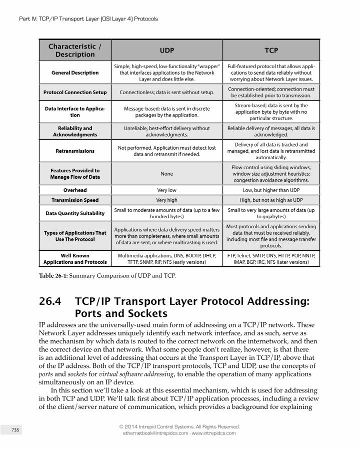
738
Part IV: TCP/IP Transport Layer (OSI Layer 4) Protocols
© 2014 Intrepid Control Systems. All Rights Reserved. [email protected] • www.intrepidcs.com
Characteristic / Description UDP TCP
General DescriptionSimple, high-speed, low-functionality “wrapper”
that interfaces applications to the Network Layer and does little else.
Full-featured protocol that allows appli-cations to send data reliably without
worrying about Network Layer issues.
Protocol Connection Setup Connectionless; data is sent without setup. Connection-oriented; connection must be established prior to transmission.
Data Interface to Applica-tion
Message-based; data is sent in discrete packages by the application.
Stream-based; data is sent by the application byte by byte with no
particular structure.
Reliability and Acknowledgments
Unreliable, best-effort delivery without acknowledgments.
Reliable delivery of messages; all data is acknowledged.
Retransmissions Not performed. Application must detect lost data and retransmit if needed.
Delivery of all data is tracked and managed, and lost data is retransmitted
automatically.
Features Provided to Manage Flow of Data None
Flow control using sliding windows; window size adjustment heuristics; congestion avoidance algorithms.
Overhead Very low Low, but higher than UDP
Transmission Speed Very high High, but not as high as UDP
Data Quantity Suitability Small to moderate amounts of data (up to a few hundred bytes)
Small to very large amounts of data (up to gigabytes)
Types of Applications That Use The Protocol
Applications where data delivery speed matters more than completeness, where small amounts of data are sent; or where multicasting is used.
Most protocols and applications sending data that must be received reliably,
including most file and message transfer protocols.
Well-Known Applications and Protocols
Multimedia applications, DNS, BOOTP, DHCP, TFTP, SNMP, RIP, NFS (early versions)
FTP, Telnet, SMTP, DNS, HTTP, POP, NNTP, IMAP, BGP, IRC, NFS (later versions)
Table 26-1: Summary Comparison of UDP and TCP.
26.4 TCP/IP Transport Layer Protocol Addressing: Ports and Sockets
IP addresses are the universally-used main form of addressing on a TCP/IP network. These Network Layer addresses uniquely identify each network interface, and as such, serve as the mechanism by which data is routed to the correct network on the internetwork, and then the correct device on that network. What some people don’t realize, however, is that there is an additional level of addressing that occurs at the Transport Layer in TCP/IP, above that of the IP address. Both of the TCP/IP transport protocols, TCP and UDP, use the concepts of ports and sockets for virtual software addressing, to enable the operation of many applications simultaneously on an IP device.
In this section we’ll take a look at this essential mechanism, which is used for addressing in both TCP and UDP. We’ll talk first about TCP/IP application processes, including a review of the client/server nature of communication, which provides a background for explaining
739
Chapter 26: Overview of TCP/IP Transport Layer Protocols and Addressing (Ports and Sockets)
© 2014 Intrepid Control Systems. All Rights Reserved. [email protected] • www.intrepidcs.com
how ports and sockets are used. We’ll then look at ports themselves and show how they enable the multiplexing of data over an IP address. We’ll examine port number ranges and how they are assigned to server and client processes for common applications. We’ll then introduce the concept of the socket, and how sockets are used for connection identification and to allow multiple devices to talk to a single port on another device.
26.4.1 TCP/IP Processes, Multiplexing and Client/Server Application Roles
When we examine the operation of TCP/IP from the perspective of the Internet Protocol, we talk very generically about sending and receiving datagrams. To the IP layer software that sends and received IP messages, the higher-level application they come from and go to is really unimportant: to IP, “a packet is a packet”, pretty much. All datagrams are packaged and routed in the same way (with a few exceptions) and IP is mainly concerned with lower-level aspects of moving them between devices in an efficient manner.
It’s important to remember, however, that this is really an abstraction, for the convenience of describing layer 3 operation, which doesn’t consider how datagrams are really generated and used above that point. Layer 4 represents a transition point between the OSI model hardware-related layers (1, 2, and 3) and the software-related layers (5, 6, and 7). This means the TCP/IP Transport Layer protocols, TCP and UDP, do need to pay attention to the way that software uses TCP/IP, even if IP really does not.
Ultimately, the entire point of having networks, internetworks and protocols suites like TCP/IP is to enable networking applications, which are the software programs that users run over these interconnected systems. In fact, most of us will be running many different applications simultaneously. For example, you might be using a World Wide Web browser to check the news, an FTP client to upload some pictures to share with family, and an instant messaging program to discuss something with a friend or colleague. In fact, it is common to have multiple instances of a single application. The most common example is having multiple Web browser windows or tabs open—some folks can have as many as 100 going at a time!
Multiplexing and Demultiplexing Most communication in TCP/IP takes the form of exchanges of information between a program running on one device, and a matching program on another device. Each instance of an application represents a copy of that application software that needs to send and receive information and is called a process.
A TCP/IP application process is any piece of networking software that sends and receives information using the TCP/IP protocol suite. This includes both “classic” end-user applications such as the ones described above, as well as support protocols that behave as applications when they send messages. Examples of the latter would include an administrative protocol such as the Simple Network Management Protocol (SNMP) or even a routing protocol such as the Border Gateway Protocol (BGP), which sends messages using TCP just like an application does.
So, a typical TCP/IP host has multiple processes each needing to send and receive datagrams. All of them, however, must be sent using the same interface to the internetwork, through the IP layer. This means that the data from all applications (with some possible exceptions) is “funneled down”, initially to the Transport Layer, where it is handled by
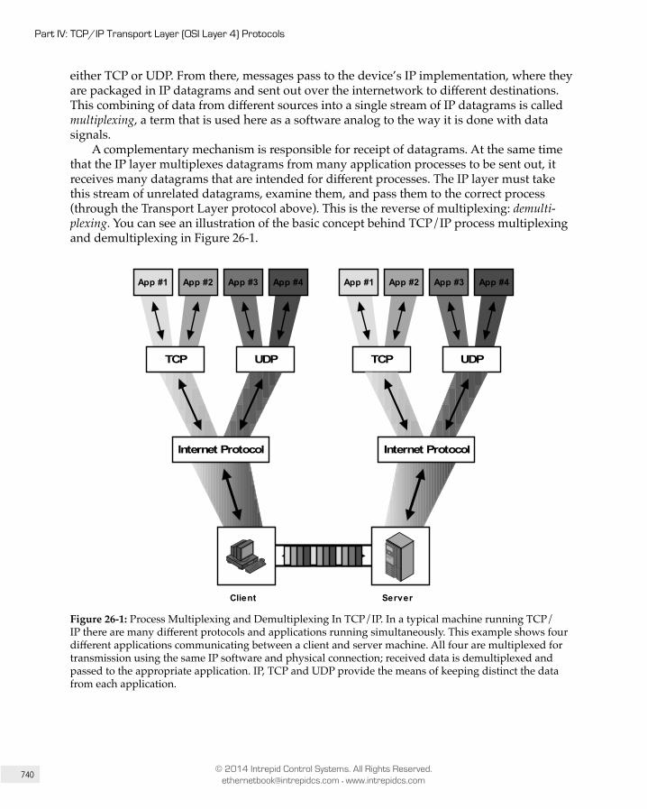
740
Part IV: TCP/IP Transport Layer (OSI Layer 4) Protocols
© 2014 Intrepid Control Systems. All Rights Reserved. [email protected] • www.intrepidcs.com
either TCP or UDP. From there, messages pass to the device’s IP implementation, where they are packaged in IP datagrams and sent out over the internetwork to different destinations. This combining of data from different sources into a single stream of IP datagrams is called multiplexing, a term that is used here as a software analog to the way it is done with data signals.
A complementary mechanism is responsible for receipt of datagrams. At the same time that the IP layer multiplexes datagrams from many application processes to be sent out, it receives many datagrams that are intended for different processes. The IP layer must take this stream of unrelated datagrams, examine them, and pass them to the correct process (through the Transport Layer protocol above). This is the reverse of multiplexing: demulti-plexing. You can see an illustration of the basic concept behind TCP/IP process multiplexing and demultiplexing in Figure 26-1.
Client Server
App #4App #3App #2App #1
TCP UDP
App #4App #3App #2App #1
TCP UDP
Internet Protocol Internet Protocol
Figure 26-1: Process Multiplexing and Demultiplexing In TCP/IP. In a typical machine running TCP/IP there are many different protocols and applications running simulta neously. This example shows four different applications communicating between a client and server machine. All four are multiplexed for transmission using the same IP software and physical connection; received data is demultiplexed and passed to the appropriate application. IP, TCP and UDP provide the means of keeping distinct the data from each application.

741
Chapter 26: Overview of TCP/IP Transport Layer Protocols and Addressing (Ports and Sockets)
© 2014 Intrepid Control Systems. All Rights Reserved. [email protected] • www.intrepidcs.com
Key Information: TCP/IP is designed to allow many different applications to send and receive data simultaneously using the same
software on a given device. To accomplish this, it is necessary to multiplex transmitted data from many sources as it is passed down to the IP layer. As a stream of IP datagrams is received, it is demultiplexed and the appropriate data passed to each application software instance on the receiving host.
TCP/IP Client Processes and Server Processes There’s another characteristic of TCP/IP software that is very important to understanding how the Transport Layer and higher layers of the suite operate: it is generally asymmetric. This means that when a TCP/IP application process on one computer tries to talk to an application process on another computer, the two processes are usually not exactly the same. They are instead complements of each other, designed to function together as a team.
We’ve seen earlier in the book that most networking applications use a client/server model of operation. This term can be used to refer to the roles of computers, where a server is a relatively powerful machine that provides services to a large number of user-operated clients. It also applies to software, where a client process is usually one that runs on a client machine and initiates contact to perform some sort of function. A server process usually runs on a hardware server, and listens for requests from clients and responds to them.
The classic example of this is, of course, the World Wide Web, which uses the Hypertext Transfer Protocol (HTTP), a good example of an application protocol. A Web browser is an HTTP client, normally running on an end-user client machine. It initiates an exchange of data by sending a request to a Web (HTTP) server. A server process on that Web server hears the request and replies either with the requested item(s)—a Web page or other data—or an error message. The server is usually specifically designed to handle many incoming client requests, and in many cases for little else.
The fact that many application processes run simultaneously and have their data multiplexed for transmission is the impetus for why higher-level addressing is a necessity in TCP/IP. The client/server arrangement used by TCP/IP has an important impact on the way that ports are used and the mechanisms for how they are assigned. The next two topics explore these concepts more completely.
26.4.2 TCP/IP Ports: Transport Layer (TCP/UDP) Addressing
A typical host on a TCP/IP internetwork has many different software application processes running concurrently. Each generates data that it sends to either TCP or UDP, which in turn passes it to IP for transmission. This multiplexed stream of datagrams is sent out by the IP layer to various destinations. Simultaneously, each device’s IP layer is receiving datagrams that originated in numerous application processes on other hosts. These need to be demul-tiplexed, so they end up at the correct process on the device that receives them.

742
Part IV: TCP/IP Transport Layer (OSI Layer 4) Protocols
© 2014 Intrepid Control Systems. All Rights Reserved. [email protected] • www.intrepidcs.com
Multiplexing and Demultiplexing Using Ports The question is: how do we demultiplex a sequence of IP datagrams that need to go to different application processes? Let’s consider a particular host with a single network interface bearing the IP address 24.156.79.20. Normally, every datagram received by the IP layer will have this value in the IP Destination Address field. Consecutive datagrams received by IP may contain a piece of a file you are downloading with your Web browser, an e-mail sent to you by your brother, and a line of text a buddy wrote in response to a Facebook post. How does the IP layer know which datagrams go where, if they all have the same IP address?
The first part of the answer lies in the Protocol field included in the header of each IP datagram. This field carries a code that identifies the protocol that sent the data to IP. Since most end-user applications use TCP or UDP at the transport layer, the Protocol field in a received datagram tells IP to pass data to either TCP or UDP as appropriate.
Of course, this just defers the problem to the Transport Layer: both TCP and UDP are used by many applications at once, and so they must figure out where to send the data. To make this possible, an additional addressing element is necessary, which allows a more specific location—a software process—to be identified within a particular IP address. In TCP/IP, this Transport Layer address is called a port.
Key Information: TCP/IP transport layer addressing is accomplished using TCP and UDP ports. Each port number within a
particular IP device identifies a particular software process.
Source Port and Destination Port Numbers In both UDP and TCP messages two addressing fields appear, for a Source Port and a Destination Port. These are analogous to the fields for source address and destination address at the IP level, but at a higher level of detail. They identify the originating process on the source machine, and the destination process on the destination machine. They are filled in by the TCP or UDP software before transmission, and used to direct the data to the correct process on the destination device upon reception.
TCP and UDP port numbers are 16 bits in length, so valid port numbers can theoretically take on values from 0 to 65,535. As we will see, these values are divided into ranges for different purposes, with certain ports reserved for particular uses.
One fact that is sometimes a bit confusing is that both UDP and TCP use the same range of port numbers, and they are independent. So, in theory, it is possible for UDP port number 77 to refer to one application process and TCP port number 77 to refer to an entirely different one. There is no ambiguity—at least to the computers—because as mentioned above, each IP datagram contains a Protocol field that specifies whether it is carrying a TCP message or a UDP message. IP passes the datagram to either TCP or UDP, which then sends the message on to the right process using the port number in the TCP or UDP header. This mechanism is illustrated in Figure 26-2.
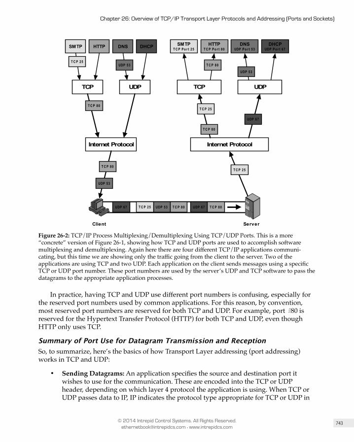
743
Chapter 26: Overview of TCP/IP Transport Layer Protocols and Addressing (Ports and Sockets)
© 2014 Intrepid Control Systems. All Rights Reserved. [email protected] • www.intrepidcs.com
TCP UDP
Internet Protocol
DHCPUDP Po r t 67
DNSUDP Po r t 53
HTTPT C P Po r t 80
SMTPT C P Po r t 25
Client Server
TCP UDP
Internet Protocol
DHCPDNSHTTPSMTP
T C P 80
UDP 53 T C P 80
UDP 53
UDP 53 T C P 80 UDP 67 T C P 80UDP 67
T C P 80
UDP 67
UDP 53
T C P 80
T C P 25
T C P 25
T C P 25
T C P 25
Figure 26-2: TCP/IP Process Multiplexing/Demultiplexing Using TCP/UDP Ports. This is a more “concrete” version of Figure 26-1, showing how TCP and UDP ports are used to accomplish software multiplexing and demultiplexing. Again here there are four different TCP/IP applications communi-cating, but this time we are showing only the traffic going from the client to the server. Two of the applications are using TCP and two UDP. Each application on the client sends messages using a specific TCP or UDP port number. These port numbers are used by the server’s UDP and TCP software to pass the datagrams to the appropriate application processes.
In practice, having TCP and UDP use different port numbers is confusing, especially for the reserved port numbers used by common applications. For this reason, by convention, most reserved port numbers are reserved for both TCP and UDP. For example, port #80 is reserved for the Hypertext Transfer Protocol (HTTP) for both TCP and UDP, even though HTTP only uses TCP.
Summary of Port Use for Datagram Transmission and Reception So, to summarize, here’s the basics of how Transport Layer addressing (port addressing) works in TCP and UDP:
• Sending Datagrams: An application specifies the source and destination port it wishes to use for the communication. These are encoded into the TCP or UDP header, depending on which layer 4 protocol the application is using. When TCP or UDP passes data to IP, IP indicates the protocol type appropriate for TCP or UDP in

744
Part IV: TCP/IP Transport Layer (OSI Layer 4) Protocols
© 2014 Intrepid Control Systems. All Rights Reserved. [email protected] • www.intrepidcs.com
the Protocol field of the IP datagram. The source and destination port numbers are encapsulated as part of the TCP or UDP message, within the IP datagram’s data area.
• Receiving Datagrams: The IP software receives the datagram, inspects the Protocol field and decides to which protocol the datagram belongs (in this case, TCP or UDP, but of course there are other protocols that use IP directly, such as ICMP). TCP or UDP receives the datagram and passes its contents to the appropriate process based on the destination port number.
Key Information: Application process multiplexing and demultiplexing in TCP/IP is implemented using the IP Protocol field
and the UDP/TCP Source Port and Desti nation Port fields. Upon transmission, the Protocol field is given a number to indicate whether TCP or UDP was used, and the port numbers are filled in to indicate the sending and receiving software process. The device receiving the datagram uses the Protocol field to determine whether TCP or UDP was used, and then passes the data to the software process indicated by the Destination Port number.
Note: Beware that the term port has many meanings aside from this one in TCP/IP. One obvious example is that a physical outlet in a
network device is often called a port. Usually one can discern whether the “port” in question refers to a hardware port or a software port from context, but watch out for potential ambiguity.
26.4.3 TCP/IP Application Assignments and Server Port Number Ranges: Well-Known, Registered and Dynamic/Private Ports
The port numbers we discussed in the previous topic provide a method of transport-layer addressing that allows many applications to use TCP and UDP simultaneously. By speci fying the appropriate destination port number, an application sending data can be sure that the right process on the destination device will received the message. Unfortunately, there’s still a problem we have to work on before this addressing system will work.
The Problem: Identifying Particular Processes on A Server To explain this, we need to go back to a familiar example: using the World Wide Web. We fire up our Web browser, which is client software that sends requests using HTTP. We need to either know the IP address of the Web site we want to access, or we may have the IP address
745
Chapter 26: Overview of TCP/IP Transport Layer Protocols and Addressing (Ports and Sockets)
© 2014 Intrepid Control Systems. All Rights Reserved. [email protected] • www.intrepidcs.com
supplied to us automatically through the Domain Name System (DNS). Once we have the address, the Web browser can generate an HTTP message and send it to the Web site’s IP address.
But this HTTP message is being sent not “just anywhere” at that IP address: it is intended for the Web server process on the site we are trying to reach. The problem is: how does the Web browser (client process) know which port number has been assigned to the server process on the Web site? Port numbers can range from 0 to 65,535, which means a lot of choices. And in theory, every Web site could assign a different port number to its Web server process.
The Solution: Reserved Port Numbers There are a couple of different ways to resolve this problem. TCP/IP takes what is probably the simplest possible approach: it reserves certain port numbers for particular applications. Each common application has a specific port number that is assigned to it for use by server processes, which “listen” for requests intended for them and then respond accordingly. To avoid chaos, the software that implements a particular server process normally uses the same reserved port number on every IP device, so clients can find it easily.
In our example, the reserved port number for HTTP is 80. Every Web browser just “knows” that Web sites are designed to listen for requests sent to port 80. They will thus use this value in requests, to ensure the IP and TCP software on the Web browser direct these HTTP messages to the Web server software. It is possible for a particular Web server to use a different port number, but in this case, the user of the Web browser must be informed of this number somehow, and must explicitly tell the Web browser to use it instead of the default port number (80). Similarly, protocols other than HTTP used on the Web will employ a different port number, such as 443 for HTTP over the Secure Sockets Layer (SSL).
Key Information: To allow client devices to more easily establish connections to TCP/IP servers, server processes for
common applications use universal server port numbers that clients are pre-programmed to know to use by default.
TCP/UDP Port Number Ranges Obviously this system requires universal agreement on port assignments. Thus, this becomes another situation where a central authority is needed to manage a list of port assignments that everyone uses. For TCP/IP, it is the same authority responsible for the assignment and coordination of other centrally-managed numbers, including IP addresses, IP Protocol numbers and so forth: the Internet Assigned Numbers Authority (IANA).
As we have seen, there are 65,536 port numbers that can be used for processes. But there are also a fairly large number of TCP/IP applications, and the list grows every year. IANA needs to carefully manage the port number “address space” to ensure that port numbers are not wasted on protocols that won’t be widely used, while also providing flexibility for
746
Part IV: TCP/IP Transport Layer (OSI Layer 4) Protocols
© 2014 Intrepid Control Systems. All Rights Reserved. [email protected] • www.intrepidcs.com
organizations that need to make use of obscure applications. To this end, the full spectrum of TCP and UDP port numbers is divided into three ranges:
• Well-Known (Privileged) Port Numbers (0 to 1,023): These port numbers are managed by IANA and reserved for only the most universal TCP/IP applications. The IANA assigns these port numbers only to protocols that have been standardized using the TCP/IP RFC process, that are in the process of being standardized, or that are likely to be standardized in the future. On most computers, these port numbers are used only by server processes run by system administrators or privileged users. These generally correspond to processes that implement key IP applications, such as Web servers, FTP servers and the like. For this reason, these are sometimes called system port numbers.
• Registered (User) Port Numbers (1,024 to 49,151): There are many applications that need to use TCP/IP but are not specified in RFCs, or are not so universally used that they warrant a worldwide well-known port number. To ensure that these various applications do not conflict with each other, IANA uses the bulk of the overall port number range for registered port numbers. Anyone who creates a viable TCP/IP server application can request to reserve one of these port numbers, and if approved, the IANA will register that port number and assign it to the appli cation. These port numbers are generally accessible by any user on a system and are therefore sometimes called user port numbers.
• Private/Dynamic Port Numbers (49,152 to 65,535): These ports are neither reserved nor maintained by IANA. They can be used for any purpose without registration, so they are appropriate for a private protocol used only by a particular organization
The existence of these ranges ensures that there will be universal agreement on how to access a server process for the most common TCP/IP protocols, while also allowing flexi-bility for special applications. Most of the TCP/IP applications and application protocols use numbers in the well-known port number range for their servers. These port numbers are not generally used for client processes, but there are some exceptions. For example, port 68 is reserved for a client using the Boostratp Protocol (BOOTP) or Dynamic Host Configuration Protocol (DHCP).
Key Information: Port numbers assignments are managed by IANA to ensure universal compatibility around the global Internet.
The numbers are divided into three ranges: well-known port numbers used for the most common applications, registered port numbers for other applications, and private/dynamic port numbers that can be used without IANA registration.
747
Chapter 26: Overview of TCP/IP Transport Layer Protocols and Addressing (Ports and Sockets)
© 2014 Intrepid Control Systems. All Rights Reserved. [email protected] • www.intrepidcs.com
26.4.4 TCP/IP Client (Ephemeral) Ports and Client/Server Application Port Use
The significance of the asymmetry between clients and servers in TCP/IP becomes evident when we examine in detail how port numbers are used. Since clients initiate application data transfers using TCP and UDP, it is they that need to know the port number of the server process. Consequently, it is servers that are required to use universally-known port numbers, and so the well-known and registered port numbers described above typically identify server processes. They are used as the destination port number in requests sent by clients.
In contrast, servers respond to clients; they do not initiate contact with them. Thus, the client doesn’t need to use a reserved port number. In fact, this is really an understatement: a server shouldn’t use a well-known or registered port number to send responses back to clients. The reason is that it is possible for a particular device to have both client and server software of the same protocol running on the same machine. If a server received an HTTP request on port 80 of its machine and sent the reply back to port 80 on the client machine, it would be sending the reply to the client machine’s HTTP server process (if present) and not the client process that sent the initial request.
To know where to send the reply, the server must know the port number the client is using. This is supplied by the client as the Source Port in the request, and then used by the server as the destination port to send the reply. Client processes don’t use well-known or regis tered ports. Instead, each client process is assigned a temporary port number for its use. This is commonly called an ephemeral port number.
Note: Your $10 word for the day: ephemeral: “short-lived; existing or continuing for a short time only.”
— Webster’s Revised Unabridged Dictionary.
Ephemeral Port Number Assignment Ephemeral port numbers are assigned as needed to processes by the TCP/IP software. Obviously, each client process running concurrently needs to use a unique ephemeral port number, so the TCP and UDP layers must keep track of which are in use. These port numbers are generally assigned in a pseudo-random manner from a reserved pool of numbers. We say “pseudo-random” because there is no specific meaning to an ephemeral port number assigned to a process, so a random one could be selected for each client process. However, since it is necessary to reuse the port numbers in this pool over time, many implementations use a set of rules to minimize the chance of confusion due to the recycling of these values.
Consider a client process that just used ephemeral port number 4,121 to send a request, received a reply, and then terminated. Suppose we immediately reallocate 4,121 to some other process. However, the server accessed by the prior user of port 4,121 for some reason sent an extra reply. It would go to the new process, creating confusion. To avoid this, it is wise to wait as long as possible before reusing port number 4,121 for another client process. Some implementations will therefore cycle through the port numbers in to ensure the
748
Part IV: TCP/IP Transport Layer (OSI Layer 4) Protocols
© 2014 Intrepid Control Systems. All Rights Reserved. [email protected] • www.intrepidcs.com
maximum amount of time elapses between consecutive uses of the same ephemeral port number.
Key Information: Well-known and registered port numbers are needed for server processes, since a client must know the
server’s port number to initiate contact. In contrast, client processes can use any port number. Each time a client process initiates a UDP or TCP communication it is assigned a temporary, or ephemeral, port number to use for that conversation. These port numbers are assigned in a pseudo-random way, since the exact number used is not important, as long as each process has a different number.
Ephemeral Port Number Ranges The range of port numbers that is used for ephemeral ports on a device also depends on the implementation. The “classic” ephemeral port range was established by the TCP/IP implementation in BSD (Berkeley Standard Distribution) UNIX, where it was defined as 1,024 to 4,999, providing 3,976 ephemeral numbers. This seems like a very large value, and it is indeed usually more than enough for a typical client. However, the size of this number can be deceiving. Many applications use more than one process, and it is theoretically possible to run out of ephemeral port numbers on a very busy device. For this reason, most of the time the ephemeral port number range can be changed. The default range may also be different for other operating systems.
Just as well-known and registered port numbers are used for server processes, ephemeral port numbers are for client processes only. This means that the use of a range of addresses from 1,024 to 4,999 does not conflict with the use of that same range for registered port numbers as seen in the previous topic.
Port Number Use During a Client/Server Exchange So, let’s return to the matter of client/server application message exchange. Once assigned an ephemeral port number, it is used as the source port in the client’s request TCP/UDP message. The server receives the request, and then generates a reply. In forming this response message, it swaps the source and destination port numbers, just as it does the source and destination IP addresses. So, the server’s reply is sent from the well-known or registered port number on the server process, back to the ephemeral port number on the client machine.
Phew, confusing… quick, back to our example! :) Our Web browser, with IP address 177.41.72.6 wants to send an HTTP request to a particular Web site at IP address 41.199.222.3. The HTTP request is sent using TCP, with a Destination Port number of 80 (the one reserved for HTTP servers). The Source Port number is allocated from a pool of ephemeral ports; let’s say it’s port 3,022. When the HTTP request arrives at the Web server it is conveyed to port 80 where the HTTP server receives it. That process generates a reply, and sends it back to 177.41.72.6, using Destination Port 3,022 and Source Port 80. The two processes can exchange
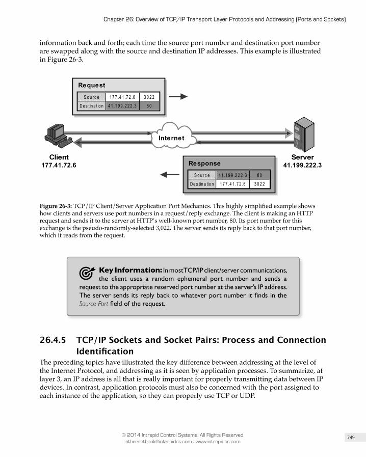
749
Chapter 26: Overview of TCP/IP Transport Layer Protocols and Addressing (Ports and Sockets)
© 2014 Intrepid Control Systems. All Rights Reserved. [email protected] • www.intrepidcs.com
information back and forth; each time the source port number and destination port number are swapped along with the source and destination IP addresses. This example is illustrated in Figure 26-3.
S o u r c e 1 7 7 .4 1 .7 2 .6 3 0 2 2
D e s t in a t io n 4 1 .1 9 9 .2 2 2 .3 8 0
Request
S o u r c e 4 1 .1 9 9 .2 2 2 .3 8 0
D e s t in a t io n 1 7 7 .4 1 .7 2 .6 3 0 2 2
Response
Internet
Client177.41.72.6
Server41.199.222.3
Figure 26-3: TCP/IP Client/Server Application Port Mechanics. This highly simplified example shows how clients and servers use port numbers in a request/reply exchange. The client is making an HTTP request and sends it to the server at HTTP’s well-known port number, 80. Its port number for this exchange is the pseudo-randomly-selected 3,022. The server sends its reply back to that port number, which it reads from the request.
Key Information: In most TCP/IP client/server communications, the client uses a random ephemeral port number and sends a
request to the appropriate reserved port number at the server’s IP address. The server sends its reply back to whatever port number it finds in the Source Port field of the request.
26.4.5 TCP/IP Sockets and Socket Pairs: Process and Connection Identification
The preceding topics have illustrated the key difference between addressing at the level of the Internet Protocol, and addressing as it is seen by application processes. To summarize, at layer 3, an IP address is all that is really important for properly transmitting data between IP devices. In contrast, application protocols must also be concerned with the port assigned to each instance of the application, so they can properly use TCP or UDP.
750
Part IV: TCP/IP Transport Layer (OSI Layer 4) Protocols
© 2014 Intrepid Control Systems. All Rights Reserved. [email protected] • www.intrepidcs.com
Sockets: Process Identification What this all means is that the overall identification of an application process actually uses the combination of the IP address of the host it runs on—or the network interface over which it is talking, to be more precise—and the port number which has been assigned to it. This combined address is called a socket. Sockets are specified using the following notation:
<IP Address>:<Port Number>
So, for example, if we have a Web site running on IP address 41.199.222.3, the socket corresponding to the HTTP server for that site would be 41.199.222.3:80.
Key Information: The overall identifier of a TCP/IP application process on a device is the combination of its IP address and port
number, which is called a socket.
You will also sometimes see a socket specified using a host name instead of an IP address, like this:
<Host Name>:<Port Number>
To use this descriptor, the name must first be resolved to an IP address using DNS. For example, you might find a Web site URL like this: “http://www.thisisagreatsite.com:8080”. This tells the Web browser to first resolve the name “www.thisisagreatsite.com” to an IP address using DNS, and then send a request to that address using the non-standard server port 8080, which is occasionally used instead of port 80 since it resembles it.
The socket is a very fundamental concept to the operation of TCP/IP application software. In fact, it is the basis for an important TCP/IP application program interface (API) with the same name: Sockets. A version of this API for Windows is called Windows Sockets or WinSock, which you may have heard of before. These APIs allow application programs to easily use TCP/IP to communicate.
Socket Pairs: Connection Identification So, the exchange of data between a pair of devices consists of a series of messages sent from a socket on one device to a socket on the other. Each device will normally have multiple such simultaneous conversations going on. In the case of TCP, a connection is established for each pair of devices for the duration of a communication session. These connections must be managed, and this requires that they be uniquely identified. This is done using the pair of socket identifiers for each of the two devices that are connected.
751
Chapter 26: Overview of TCP/IP Transport Layer Protocols and Addressing (Ports and Sockets)
© 2014 Intrepid Control Systems. All Rights Reserved. [email protected] • www.intrepidcs.com
Key Information: Each device may have multiple TCP connections active at any given time. Each connection is uniquely
identified using the combination of the client socket and server socket, which in turn contains four elements: the client IP address and port, and the server IP address and port.
Let’s return to the example we used in the previous topic (Figure 26-3). We are sending an HTTP request from our client at 177.41.72.6 to the Web site at 41.199.222.3. The server for that Web site will use well-known port number 80, so its socket is 41.199.222.3:80, as we saw before. We have been ephemeral port number 3,022 for our Web browser, so the client socket is 177.41.72.6:3022. The overall connection between these devices can be described using this socket pair:
(41.199.222.3:80, 177.41.72.6:3022)
We’ll see much more on how TCP identifies connections in the next few chapters.Unlike TCP, UDP is a connectionless protocol, so it obviously doesn’t use connections.
The pair of sockets on the sending and receiving devices can still be used to identify the two processes exchanging data, but since there are no connections, the socket pair doesn’t have the significance that it does in TCP.
26.4.6 Common TCP/IP Applications and Assigned Well-Known and Registered Port Numbers
The great popularity of the TCP/IP protocol suite has led to the development of literally thousands of different applications and protocols. Most of these use the client/server model of operation that we discussed earlier in this chapter. Server processes for a particular application are designed to use a particular reserved port number, with clients using an ephemeral (temporary) port number to initiate a connection to the server.
Management of Reserved Port Numbers To ensure that everyone agrees on which port numbers server applications for each appli-cation should use, they are centrally managed by IANA, as mentioned earlier. Originally, IANA kept the list of well-known and registered port numbers in a lengthy text document, along with all the many other parameters for which IANA was centrally responsible (such as IP Protocol field numbers, Type and Code field values for ICMP, and so on). These were published on a periodic basis in Internet (RFC) standards documents titled Assigned Numbers.
This system worked fine in the early days of the Internet, but by the mid-1990s, these values were changing so rapidly that using the RFC process was not feasible. It was too much work to keep publishing them, and the RFC was practically out of date the day after it was put out.
The last Assigned Numbers standard was RFC 1700, published in October 1994. After that time, IANA moved to a set of World Wide Web documents containing the parameters they
752
Part IV: TCP/IP Transport Layer (OSI Layer 4) Protocols
© 2014 Intrepid Control Systems. All Rights Reserved. [email protected] • www.intrepidcs.com
manage. This allowed IANA to keep the lists constantly up to date, and for TCP/IP users to be able to get more current information. RFC 1700 was officially obsoleted in 2002. Complete information on all the parameters maintained by IANA can be found at http://www.iana.org/protocols. The URL of the file containing TCP/UDP port assignments is http://www.iana.org/assignments/service-names-port-numbers/service-names-port-numbers.xhtml.
The link mentioned above contains the definitive list of all well-known and registered TCP and UDP port assignments. Each port number is assigned a short keyword, with a brief description of the protocol that uses it. But there are two problems with this document. The first is that it is incredibly long: as of this writing, it has 136 different pages listing protocols, most of which are for obscure applications that you have probably never heard of before. This makes it hard to easily see the port assignments for the protocols that are most commonly used.
The other problem with this document is that it shows the same port number as reserved for both TCP and UDP for an application. As we mentioned earlier, TCP and UDP port numbers are actually independent, so one could in theory assign TCP port 80 to one server appli cation type and UDP port 80 to another. It was believed that this would lead to confusion, so with very few exceptions, the same port number is shown in the list for the same application for both TCP and UDP. This makes sense, but showing this in the list has a drawback: you can’t tell which protocol the application actually uses, and which has just been reserved for consistency.
Given all that, we’ve decided to include here a couple of summary tables that show the well-known and registered port numbers for some of the most common TCP/IP applications, as well as indicating whether the protocol uses TCP, UDP or both.
Common Well-Known Port Numbers and Applications Table 26-2 lists the well-known port numbers for the most common TCP/IP application protocols.
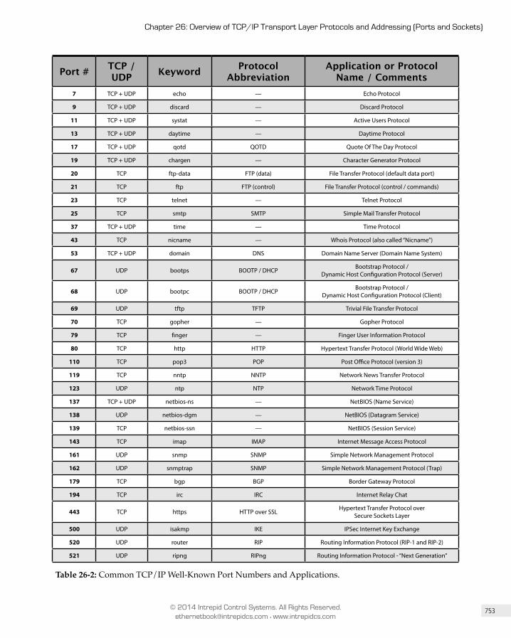
753
Chapter 26: Overview of TCP/IP Transport Layer Protocols and Addressing (Ports and Sockets)
© 2014 Intrepid Control Systems. All Rights Reserved. [email protected] • www.intrepidcs.com
Port # TCP / UDP Keyword Protocol
Abbrevi ationApplication or Protocol
Name / Comments7 TCP + UDP echo — Echo Protocol
9 TCP + UDP discard — Discard Protocol
11 TCP + UDP systat — Active Users Protocol
13 TCP + UDP daytime — Daytime Protocol
17 TCP + UDP qotd QOTD Quote Of The Day Protocol
19 TCP + UDP chargen — Character Generator Protocol
20 TCP ftp-data FTP (data) File Transfer Protocol (default data port)
21 TCP ftp FTP (control) File Transfer Protocol (control / commands)
23 TCP telnet — Telnet Protocol
25 TCP smtp SMTP Simple Mail Transfer Protocol
37 TCP + UDP time — Time Protocol
43 TCP nicname — Whois Protocol (also called “Nicname”)
53 TCP + UDP domain DNS Domain Name Server (Domain Name System)
67 UDP bootps BOOTP / DHCP Bootstrap Protocol / Dynamic Host Configuration Protocol (Server)
68 UDP bootpc BOOTP / DHCP Bootstrap Protocol / Dynamic Host Configuration Protocol (Client)
69 UDP tftp TFTP Trivial File Transfer Protocol
70 TCP gopher — Gopher Protocol
79 TCP finger — Finger User Information Protocol
80 TCP http HTTP Hypertext Transfer Protocol (World Wide Web)
110 TCP pop3 POP Post Office Protocol (version 3)
119 TCP nntp NNTP Network News Transfer Protocol
123 UDP ntp NTP Network Time Protocol
137 TCP + UDP netbios-ns — NetBIOS (Name Service)
138 UDP netbios-dgm — NetBIOS (Datagram Service)
139 TCP netbios-ssn — NetBIOS (Session Service)
143 TCP imap IMAP Internet Message Access Protocol
161 UDP snmp SNMP Simple Network Management Protocol
162 UDP snmptrap SNMP Simple Network Management Protocol (Trap)
179 TCP bgp BGP Border Gateway Protocol
194 TCP irc IRC Internet Relay Chat
443 TCP https HTTP over SSL Hypertext Transfer Protocol over Secure Sockets Layer
500 UDP isakmp IKE IPSec Internet Key Exchange
520 UDP router RIP Routing Information Protocol (RIP-1 and RIP-2)
521 UDP ripng RIPng Routing Information Protocol - “Next Generation”
Table 26-2: Common TCP/IP Well-Known Port Numbers and Applications.

754
Part IV: TCP/IP Transport Layer (OSI Layer 4) Protocols
© 2014 Intrepid Control Systems. All Rights Reserved. [email protected] • www.intrepidcs.com
Common Registered Port Numbers and Applications The registered port numbers are by definition for protocols that are not standardized using the RFC process, so they are mostly esoteric applications that there is much point in listing at length. Table 26-3 shows a few that may be of particular interest:
Port # TCP / UDP Keyword Protocol
Abbrevi ationApplication or Protocol
Name / Comments
1512 TCP + UDP wins WINS Microsoft Windows Internet Naming Service
1701 UDP l2tp L2TP Layer Two Tunneling Protocol
1723 TCP pptp PPTP Point-To-Point Tunneling Protocol
2049 TCP + UDP nfs NFS Network File System
6000 - 6063 TCP x11 X11 X Window System
Table 26-3: Common TCP/IP Registered Port Numbers and Applications.
PART V
Audio Video Bridging (AVB)

33Chapter
Introduction to Audio Video Bridging (AVB)By Robert Boatright and Jeffrey Quesnelle. Portions adapted, with permission, from a white paper published by the AVnu Alliance.
Over the last ten years, consumer demand has led to a significant increase in audio and video options within automobiles. Once found only in luxury cars, features such as DVD playback, backup cameras, and navigation assistance have become commonplace in many mainstream automobiles. Rear Seat Entertainment (RSE) units are also growing in sophistication, with more sources and choices available literally at your fingertips.
Advances in automotive sophistication, especially in the infotainment and driver’s assistance domains, mean ever-larger amounts of audio and video data need to be distributed throughout the vehicle. Each of these options has increased the need and desire for a common networking architecture in the automobile, leading to the rapid adoption of Ethernet-based Audio Video Bridging (AVB) by automotive manufacturers.
Automotive OEMs around the globe have embraced the concept of low-bandwidth vehicle sensor/actuator networks, with the Controller Area Network (CAN) having been adopted almost universally. However, there are many new challenges involved in vehicle multimedia networking. Some of these include the need for high bandwidth, quality of service (QoS) to guarantee timely data delivery, increased scalability, low cost, good economies of scale, open standards, and wide supplier choice. This has led to much debate over the best solution for multimedia within vehicles, from both a technical and commercial perspective.

888
Part V: Audio Video Bridging (AVB)
© 2014 Intrepid Control Systems. All Rights Reserved. [email protected] • www.intrepidcs.com
Historically, the implementation of packet-switched networks has been avoided for vehicle multimedia applications due to the non-deterministic nature of packet transport. This issue has been addressed, however, with recent work by the IEEE AVB task group, which has yielded a standards-based approach for highly reliable packet networks for low-latency applications like those found within an automobile. While these AVB protocols are designed to be used on more than one type of local area networking technology, this section focuses on the application of AVB over Ethernet, our primary interest in this book. Wired Ethernet networks employing AVB protocols are very well suited to automotive deployment, due to their simplified cabling and reliability.
A primary market focus of the AVnu Alliance is the successful deployment of AVB for streaming audio/video in the automotive space. In this chapter we will introduce AVB technology and describe the features and benefits of in-vehicle networking using AVB technologies. In subsequent chapters we will discuss in more detail the actual protocols that make AVB work.
33.1 Ethernet AVB at a GlanceAVB is an enhancement to the IEEE 802 suite of open standards—which includes Ethernet (IEEE 802.3)—to provide QoS guarantees that allow a network to handle audio-visual (A/V) data. In the automotive environment, it can also satisfy more generalized time-sensitive networking requirements, opening up the possibility of a single network that handles infotainment, body control, driver assistance, and even safety-critical functions.
In order to more accurately reflect ongoing development, the name of the IEEE AVB task group has evolved to become “Time Sensitive Networking” (TSN), now one of the five area task groups of IEEE 802.1. The TSN task group is building on initial AVB standards and working to develop even greater functionality that will enable ultra-low latency control networking. While AVB and TSN can generally be viewed as interchangeable terms, we will explicitly mention new concepts introduced by TSN that require differentiation from the initial AVB standards.
To provide QoS, AVB introduces a number of new and important concepts to IEEE 802 networks. It uses priority levels to specify that some data streams are time-sensitive and distinct from ordinary traffic that is delivered only on a best-effort basis. The concept of reservation means that a certain amount of guaranteed bandwidth can be set aside across a portion of the network to handle this high-priority traffic. Protocols to manage network time, along with rigorous latency specifications, enable synchronized A/V playback. AVB also includes standard traffic shaping and forwarding rules. Finally, there are standardized methods for device discovery, enumeration, and control, allowing systems to be built and configured quickly and easily.
889
Chapter 33: Introduction to Audio Video Bridging (AVB)
© 2014 Intrepid Control Systems. All Rights Reserved. [email protected] • www.intrepidcs.com
33.2 AVB Benefits for Automotive Markets33.2.1 Simpler Cabling Means Lower Weight and
Increased ReliabilityA networked approach to cabling reduces the component cost and design complexity of in-vehicle wiring harnesses. It boosts reliability by cutting the number of interconnects, while reducing weight, and hence increasing fuel efficiency.
The use of multiplexed or network-based control communication in vehicles is already commonplace, having begun with basic control messaging and the widespread adoption of the CAN protocol. As the A/V content associated with infotainment systems has increased, it has become impractical to continue with point-to-point dedicated connections such as shielded LVDS cables. AVB over Ethernet promises a better solution using simple unshielded twisted pair (UTP) wire configured in a star or tree topology.
33.2.2 Ethernet - A Healthy EcosystemThe creators of AVB chose to base it on IEEE 802 standards for more than just sound technical reasons. Ethernet is the most robust, most deployed, most familiar networking technology on earth, and the decision to create an open standard A/V technology was intended to build on these advantages. Open standards foster strong, competitive ecosystems, with multiple silicon providers having already deployed AVB in their products. This means that tier-1 automotive suppliers can architect their solutions without dependence on a single technology provider.
This approach contrasts sharply with the situation that has existed in the automotive industry until now. The predominant technology for in-vehicle infotainment networking in recent years has been Media Oriented Serial Transport (MOST®), but many have felt that the proprietary nature of MOST has slowed development and hampered its adoption. We mentioned in our comparison of Ethernet and MOST in Chapter 8 that as early as 2008, industry analysts remarked on MOST’s relative lack of openness and affordability, which left open the door for alternatives. This prediction is now coming to pass as Ethernet is poised to take the place of MOST for in-vehicle infotainment applications.
33.2.3 Certified InteroperabilityAVB is not just open—it is a collection of IEEE standards backed by a robust and rigorous set of conformance and interoperability (C&I) tests. Defined by the AVnu Alliance, this certification program includes independent testing, ensuring interoperability across a broad ecosystem of A/V devices.
This means that OEMs will have assurances that their products will work with other AVB-certified devices, while automakers benefit from a fertile ecosystem of suppliers that grows and quickly reaches critical mass.
33.2.4 Predictability and High ReliabilityAVB core technologies—which provide prioritization, reservation, traffic shaping, and universal timing features—allow the construction of networks that meet the demanding predictability and reliability requirements of the automotive industry. IEEE 802.1Qav-2009,
890
Part V: Audio Video Bridging (AVB)
© 2014 Intrepid Control Systems. All Rights Reserved. [email protected] • www.intrepidcs.com
Forwarding and Queuing Enhancements for Time-Sensitive Streams (FQTSS), is key to this predictability. It schedules high-priority traffic throughout the network, ensuring that lower-priority data does not interfere with time-sensitive content.
IEEE 802.1Qat-2010, Stream Reservation Protocol (SRP), can be used to add a further layer of predictability. It allows endpoints to reserve end-to-end bandwidth availability across a network path between devices before an A/V stream starts, guaranteeing that bandwidth until it is explicitly released.
33.2.5 Many-to-Many Configuration FlexibilityCreating an in-vehicle network that deals with a broad range of content and control signals is a challenging task. The network must play back A/V program material from a variety of sources to a variety of destinations. It must deliver content like warning indicators and turn-by-turn navigation commands that require timely delivery, and also support features such as program muting in the event of an incoming phone call. This requires a network that is provisioned to cope with these requirements from the outset, or one that is able to reconfigure itself dynamically to deal with changing needs.
Key Information: The need for many-to-many communication is one of the fundamental attractions for automakers in moving
away from point-to-point connections to a networked A/V system.
SRP allows system endpoints to dynamically initiate and release bandwidth reservations as needed. This enables reliable A/V streaming without the need for the OEM to perform extensive hand-tuning of the network for every different vehicle option package or configuration.
33.2.6 Low LatencyMany automotive applications require very low latency—devices such as back-up or driver assist cameras, Bluetooth microphones and various signal tones are obvious examples. Just as important are the constraints imposed by outside-world systems—for instance, a hands-free car kit needs to conform to the latency limits of the cellular network. AVB protocols can meet the most rigorous of these latency requirements.
33.2.7 Precise SynchronizationThe overall aim of an automotive A/V network is to deliver a high-quality listening and viewing experience to the user by allowing A/V streams to be reconstructed faithfully at the endpoints. In addition, the automaker gains the opportunity to build a flexible network that can accommodate a diverse range of content types, sources and playback nodes. The key to both of these requirements is synchronization.
Technically, synchronization has two primary purposes. First, it provides a common time base for sampling data at a source device and presenting that data at one or more destination

891
Chapter 33: Introduction to Audio Video Bridging (AVB)
© 2014 Intrepid Control Systems. All Rights Reserved. [email protected] • www.intrepidcs.com
devices with the same relative timing. Second, it allows multiple streams to be synchronized with each other, such as front and rear audio.
AVB achieves this via IEEE 802.1AS-2011, which defines the generalized Precision Time Protocol (gPTP). gPTP provides a common time-reference base to all nodes on the network, and introduces the concept of presentation time, allowing the sending node to specify when (in network time) a packet should be presented at the receiving end. Network nodes retain their own local clock, but by exchanging timestamp information, they track “where they stand” in relation to overall network time. At the receiving end, the original sample clock can be reconstructed, not only resulting in accurate, low-jitter delivery of the content, but also allowing a single AVB network to accommodate any number of different sample rates and device types.
33.2.8 Fast BootingOne of the most challenging requirements placed on automotive multimedia systems is the need to provide “early audio/video”. The system must boot quickly and be ready to provide audio and video functionality within roughly one second of the car being started. Audio is used to play safety chimes, while video is required for rear-view cameras; both are mandated by the U.S. National Highway Traffic Safety Administration (NHTSA) to be available within two seconds of starting the car.
To satisfy these needs, the AVnu Alliance is creating a dedicated automotive profile that streamlines the startup process of automotive AVB products. The profile uses preconfigured streams, eliminating the delay associated with dynamic setup of AVB stream reservations. It also streamlines the process of establishing gPTP clock synchronization, by taking advantage of the fixed and known topology of an automotive network.
33.2.9 Scalable, Versatile TopologiesUnlike MOST, where the total network bandwidth is shared among all connected devices, AVB networks utilize bandwidth only between source and destination nodes. This is due in part to Ethernet’s use of star and tree topology, as opposed to the ring topology employed by MOST. This conservation of bandwidth allows substantially more data to flow on an AVB network than is possible in a MOST network, even if the two have equivalent nominal throughput ratings.
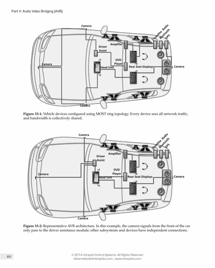
892
Part V: Audio Video Bridging (AVB)
© 2014 Intrepid Control Systems. All Rights Reserved. [email protected] • www.intrepidcs.com
Head Unit
DriverAssist
DVD Player
Rear Seat Displays
Amplifier
Satellit
e Radio
Bluetooth
GPS
CameraCamera
Camera
Camera
Figure 33-1: Vehicle devices configured using MOST ring topology. Every device sees all network traffic, and bandwidth is collectively shared.
Head Unit
DriverAssist
DVD Player
Rear Seat Displays
Amplifier
Satellit
e Radio
Bluetooth
GPS
CameraCamera
Camera
Camera
Figure 33-2: Representative AVB architecture. In this example, the camera signals from the front of the car only pass to the driver assistance module; other subsystems and devices have independent connections.
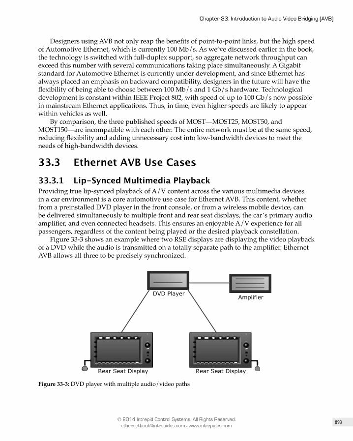
893
Chapter 33: Introduction to Audio Video Bridging (AVB)
© 2014 Intrepid Control Systems. All Rights Reserved. [email protected] • www.intrepidcs.com
Designers using AVB not only reap the benefits of point-to-point links, but the high speed of Automotive Ethernet, which is currently 100 Mb/s. As we’ve discussed earlier in the book, the technology is switched with full-duplex support, so aggregate network throughput can exceed this number with several communications taking place simultaneously. A Gigabit standard for Automotive Ethernet is currently under development, and since Ethernet has always placed an emphasis on backward compatibility, designers in the future will have the flexibility of being able to choose between 100 Mb/s and 1 Gb/s hardware. Technological development is constant within IEEE Project 802, with speed of up to 100 Gb/s now possible in mainstream Ethernet applications. Thus, in time, even higher speeds are likely to appear within vehicles as well.
By comparison, the three published speeds of MOST—MOST25, MOST50, and MOST150—are incompatible with each other. The entire network must be at the same speed, reducing flexibility and adding unnecessary cost into low-bandwidth devices to meet the needs of high-bandwidth devices.
33.3 Ethernet AVB Use Cases33.3.1 Lip-Synced Multimedia PlaybackProviding true lip-synced playback of A/V content across the various multimedia devices in a car environment is a core automotive use case for Ethernet AVB. This content, whether from a preinstalled DVD player in the front console, or from a wireless mobile device, can be delivered simultaneously to multiple front and rear seat displays, the car’s primary audio amplifier, and even connected headsets. This ensures an enjoyable A/V experience for all passengers, regardless of the content being played or the desired playback constellation.
Figure 33-3 shows an example where two RSE displays are displaying the video playback of a DVD while the audio is transmitted on a totally separate path to the amplifier. Ethernet AVB allows all three to be precisely synchronized.
DVD Player Amplifier
Rear Seat Display Rear Seat Display
Figure 33-3: DVD player with multiple audio/video paths

894
Part V: Audio Video Bridging (AVB)
© 2014 Intrepid Control Systems. All Rights Reserved. [email protected] • www.intrepidcs.com
33.3.2 Connected Car ApplicationsIn a connected car, the availability of external data is essential; in fact, it is inevitable that connected cars will become dependent on it. The demand for network bandwidth is high due to the variety of possible applications: streamed A/V content, online maps for navigation, Internet data coming into the car, and telematics data and service requests being sent out of it.
A powerful advantage of Ethernet AVB is the ability to leverage a single vehicle network to deliver all of this data, as well as internal A/V data, while still meeting the unique QoS requirements of various applications.
33.3.3 Advanced Driver Assistance Systems (ADAS)The flexibility and high bandwidth of an AVB network enables the realization of many modern Advanced Driver Assistance Systems (ADAS).
For example, an array of cameras can be connected to provide a synchronized 360° surround view of the vehicle’s environment. This view can be further enhanced with additional sensor data, sent and synchronized over the same network, to provide an augmented driver awareness system to increase safety for both motorists and pedestrians.
33.3.4 DiagnosticsVehicle diagnostics are essential for automotive OEMs to troubleshoot vehicle problems on assembly lines and at dealer service stations. No physical diagnostics exist for CAN, and only “ring-break diagnostics” exist for MOST. On the other hand, modern Ethernet PHYs have substantial physical layer diagnostic capabilities. These include the ability to automatically detect and compensate for swapped pairs, cable breaks, kinks, and impedance mismatches, all of which can reduce bandwidth or even completely prevent traffic flow. Utilizing these established and proven Ethernet diagnostics, both assembly and service issues can be more quickly discovered and corrected.
33.4 Brief Technology OverviewFour IEEE 802.1 AVB standards form the foundation of the technology promoted by the AVnu Alliance. Like other IEEE 802.1 standards, these describe interworking/bridging between various network technologies. While AVB sits architecturally above technologies such as Ethernet, this does not mean that the services provided by AVB are identical over every type of network, since each link technology has different characteristics.
Key Information: In AVB, a Talker is a device that transmits data, and a Listener a device that receives data.

895
Chapter 33: Introduction to Audio Video Bridging (AVB)
© 2014 Intrepid Control Systems. All Rights Reserved. [email protected] • www.intrepidcs.com
Note: For more information on AVB technologies, see the chapters following this one, or visit the AVnu Alliance website at www.avnu.org.
These are the three foundational standards:
• IEEE 802.1AS-2011 (gPTP): “Timing and Synchronization for Time-Sensitive Applications in Bridged Local Area Networks.” This standard describes the automatic selection of a device to be the overall master clock, which then distributes time throughout the bridged LAN to all other nodes. The gPTP clock is not used as a media clock; rather, gPTP time is used as a shared clock reference between nodes, which is used to port a media clock from Talker to Listener. Such a reference removes the need to fix the latency of packet delivery, or compute long running averages in order to estimate the actual media rate of the transmitter in the presence of substantial network jitter. IEEE 802.1AS-2011 is based on the ratified standard IEEE 1588-2008.
• IEEE 802.1Qat-2010: “Virtual Bridged Local Area Networks - Amendment 14: Stream Reservation Protocol (SRP).” This standard describes how a stream reservation may be established between a Talker and Listener in a bridged (or switched) LAN. Note that this standard has now been incorporated into the main IEEE 802.1Q VLAN standard.
• IEEE 802.1Qav-2009: “Virtual Bridged Local Area Networks - Amendment 12: Forwarding and Queuing Enhancements for Time-Sensitive Streams (FQTSS).” This standard describes a token-bucket method for shaping network traffic so that the latency and bandwidth of reserved streams can be controlled. This standard has also been “rolled up” into IEEE 802.1Q.
While each of the technologies described above can stand alone, it is their joint usage that comprises an AVB system. The interaction of the AVB standards is defined in IEEE 802.1BA-2011: “Audio/Video Bridging (AVB) Systems”. This standard describes how to build networks that are capable of transporting time-sensitive A/V data streams by defining profiles that select the features, options, configurations, defaults, protocols, and procedures for bridges, stations, and LANs . In other words, it describes the interrelationships of the core IEEE 802.1 AVB standards, and how they work together to make an AVB system.
AVB capable devices must meet the following prerequisites:
1. They must have a link supporting full-duplex operation at a nominal speed of 100 Mb/s or greater.
2. gPTP must discover exactly one peer for the device.3. The round-trip delay to the responding AVB device must be no more than a worst
case wire delay as computed from the IEEE 802.1AS-2011 “PDelay” exchange.4. An SRP reservation must exist for the port. For the majority of automotive-specific
implementations, the Stream Reservation Protocol will not run for this; rather, reservations will be statically preconfigured for greater efficiency.
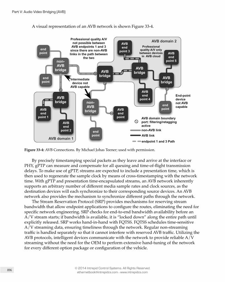
896
Part V: Audio Video Bridging (AVB)
© 2014 Intrepid Control Systems. All Rights Reserved. [email protected] • www.intrepidcs.com
A visual representation of an AVB network is shown Figure 33-4.
AVB domain 2
AVB domain 1
AVBbridge
AVBend
point 5
end point
AVBend
point 4
AVBend
point 3
non-AVB
bridge
end point
end point
end point
AVBend
point
Intermediate device not
AVB capable
Professional quality A/V only between devices
in AVB cloud
Professional quality A/V not possible between
AVB endpoints 1 and 3 since there are non-AVB links in the path between
the two
AVB domain boundary port: filtering/retagging active
non-AVB link
AVB link
End-point devicenot AVBcapable
AVBend
point 2
endpoint 1 and 3 Path
non-AVB
bridge
AVBbridge
AVBbridge
AVBbridge
AVBend
point 1
Figure 33-4: AVB Connections. By Michael Johas Teener; used with permission.
By precisely timestamping special packets as they leave and arrive at the interface or PHY, gPTP can measure and compensate for all queuing and time-of-flight transmission delays. To make use of gPTP, streams are expected to include a presentation time, which is then used to regenerate the sample clock by means of cross-timestamping with the network time. With gPTP and presentation time-encapsulated streams, an AVB network inherently supports an arbitrary number of different media sample rates and clock sources, as the destination devices will each synchronize to their corresponding source devices. An AVB network also provides the mechanism to synchronize different paths through the network.
The Stream Reservation Protocol (SRP) provides mechanisms for reserving stream bandwidth that allow endpoint applications to configure the routes, eliminating the need for specific network engineering. SRP checks for end-to-end bandwidth availability before an A/V stream starts; if bandwidth is available, it is “locked down” along the entire path until explicitly released. SRP works hand-in-hand with FQTSS. FQTSS schedules time-sensitive A/V streaming data, ensuring timeliness through the network. Regular non-streaming traffic is handled separately so that it cannot interfere with reserved AVB traffic. Utilizing the AVB protocols, intelligent devices communicate with the network to provide reliable A/V streaming without the need for the OEM to perform extensive hand-tuning of the network for every different option package or configuration of the vehicle.
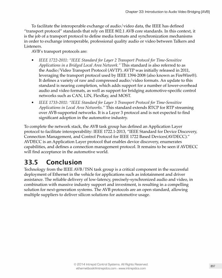
897
Chapter 33: Introduction to Audio Video Bridging (AVB)
© 2014 Intrepid Control Systems. All Rights Reserved. [email protected] • www.intrepidcs.com
To facilitate the interoperable exchange of audio/video data, the IEEE has defined “transport protocol” standards that rely on IEEE 802.1 AVB core standards. In this context, it is the job of a transport protocol to define media formats and synchronization mechanisms in order to exchange interoperable, professional quality audio or video between Talkers and Listeners.
AVB’s transport protocols are:
• IEEE 1722-2011: “IEEE Standard for Layer 2 Transport Protocol for Time-Sensitive Applications in a Bridged Local Area Network.” This standard is also referred to as the Audio/Video Transport Protocol (AVTP). AVTP was initially released in 2011, leveraging the transport protocol used by IEEE 1394-2008 (also known as FireWire®). It defines a variety of raw and compressed audio/video formats. An update to this standard is nearing completion, which adds support for a number of lower-overhead audio and video formats, as well as support for bridging automotive-specific control networks such as CAN, LIN, FlexRay, and MOST.
• IEEE 1733-2011: “IEEE Standard for Layer 3 Transport Protocol for Time-Sensitive Applications in Local Area Networks.” This standard extends RTCP for RTP streaming over AVB-supported networks. It is a Layer 3 protocol and is not expected to find significant adoption in the automotive industry.
To complete the network stack, the AVB task group has defined an Application Layer protocol to facilitate interoperability: IEEE 1722.1-2013, “IEEE Standard for Device Discovery, Connection Management, and Control Protocol for IEEE 1722 Based Devices(AVDECC).” AVDECC is an Application Layer protocol that enables device discovery, enumerates capabilities, and defines a connection management protocol. It remains to be seen if AVDECC will find acceptance in the automotive world.
33.5 ConclusionTechnology from the IEEE AVB/TSN task group is a critical component in the successful deployment of Ethernet in the vehicle for applications such as infotainment and driver assistance. The reliable delivery of low-latency, precisely-synchronized audio and video, in combination with massive industry support and investment, is resulting in a compelling solution for next-generation systems. The AVB protocols are an open standard, allowing multiple suppliers to deliver silicon solutions for automotive usage.

PART VI
Applications and Tools, Including Measurement,
Calibration and Diagnostics (MCD)

39Chapter
Automotive Ethernet Tool Applicationsby Colt Correa
Vehicle network tools have long been an important part of the development process for any in-vehicle ECU-to-ECU communication system. Networks tools for design, simulation, development, testing, and verification are used throughout the V-cycle process, whether the communication system is based on LIN, FlexRay, CAN, or MOST, and Automotive Ethernet is no exception to this rule. One of the reasons for creating this book was to promote Automotive Ethernet, and to demonstrate how Intrepid Control Systems products can make adoption of the technology easier. Accordingly, in this chapter, we will look at the application of vehicle network testing, debugging, validation, and service using tools from ICS.
Throughout the chapter we will be focusing on AE tools and comparing their application to CAN tools. As we will see, there are significant differences in the application of tools for a shared bus network like CAN verses a point-to-point switched network like Automotive Ethernet. At the end of the chapter we provide technical descriptions of all the tools referenced.
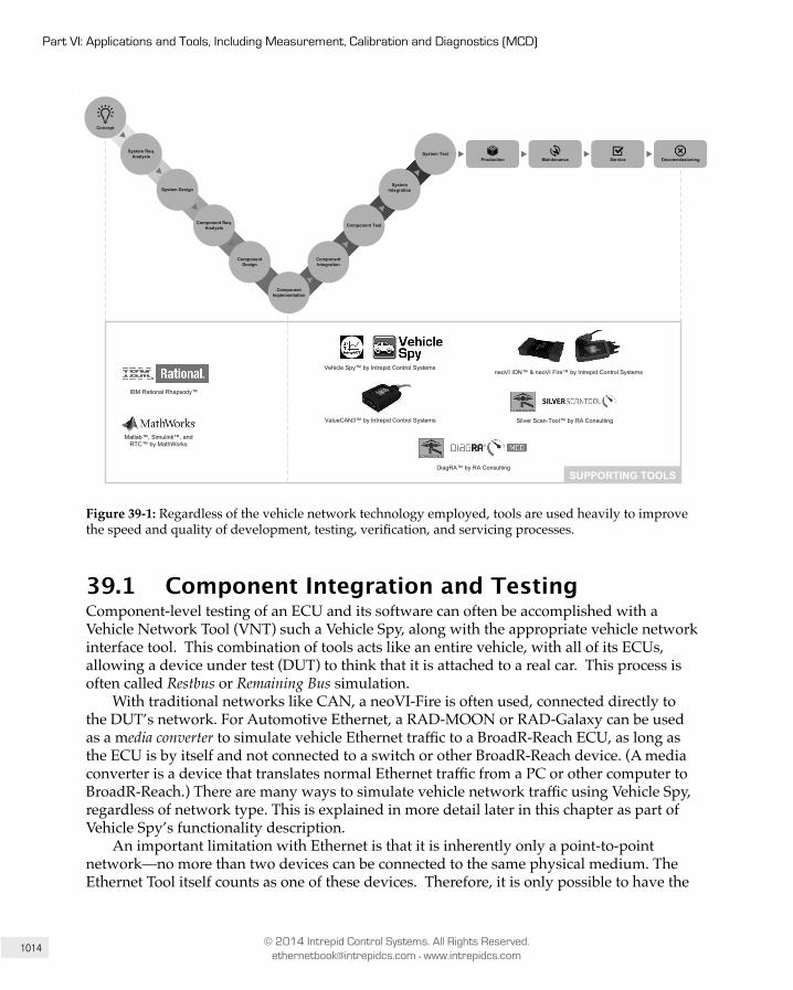
1014
Part VI: Applications and Tools, Including Measurement, Calibration and Diagnostics (MCD)
© 2014 Intrepid Control Systems. All Rights Reserved. [email protected] • www.intrepidcs.com
Component Design
Component Req. Analysis
System Design
Component Implementation
Component Integration
System Test
Component Test
System Integration
Concept
System Req. Analysis
Production Maintenance Service Decommissioning
neoVI ION™ & neoVI Fire™ by Intrepid Control Systems
IBM Rational Rhapsody™
Matlab™, Simulink™, and RTC™ by MathWorks
Silver Scan-Tool™ by RA Consulting
SUPPORTING TOOLSDiagRA™ by RA Consulting
Vehicle Spy™ by Intrepid Control Systems
ValueCAN3™ by Intrepid Control Systems
Figure 39-1: Regardless of the vehicle network technology employed, tools are used heavily to improve the speed and quality of development, testing, verification, and servicing processes.
39.1 Component Integration and TestingComponent-level testing of an ECU and its software can often be accomplished with a Vehicle Network Tool (VNT) such a Vehicle Spy, along with the appropriate vehicle network interface tool. This combination of tools acts like an entire vehicle, with all of its ECUs, allowing a device under test (DUT) to think that it is attached to a real car. This process is often called Restbus or Remaining Bus simulation.
With traditional networks like CAN, a neoVI-Fire is often used, connected directly to the DUT’s network. For Automotive Ethernet, a RAD-MOON or RAD-Galaxy can be used as a media converter to simulate vehicle Ethernet traffic to a BroadR-Reach ECU, as long as the ECU is by itself and not connected to a switch or other BroadR-Reach device. (A media converter is a device that translates normal Ethernet traffic from a PC or other computer to BroadR-Reach.) There are many ways to simulate vehicle network traffic using Vehicle Spy, regardless of network type. This is explained in more detail later in this chapter as part of Vehicle Spy’s functionality description.
An important limitation with Ethernet is that it is inherently only a point-to-point network—no more than two devices can be connected to the same physical medium. The Ethernet Tool itself counts as one of these devices. Therefore, it is only possible to have the
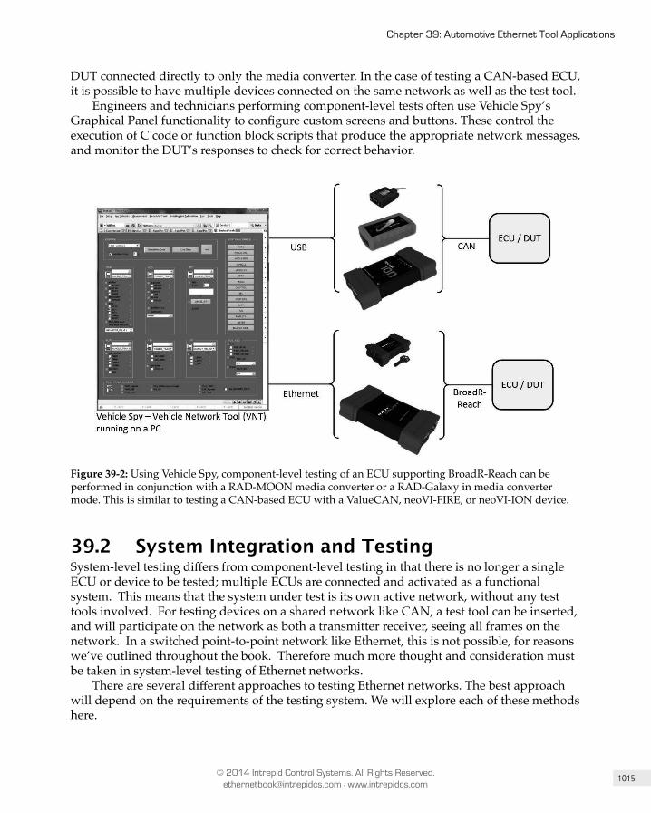
1015
Chapter 39: Automotive Ethernet Tool Applications
© 2014 Intrepid Control Systems. All Rights Reserved. [email protected] • www.intrepidcs.com
DUT connected directly to only the media converter. In the case of testing a CAN-based ECU, it is possible to have multiple devices connected on the same network as well as the test tool.
Engineers and technicians performing component-level tests often use Vehicle Spy’s Graphical Panel functionality to configure custom screens and buttons. These control the execution of C code or function block scripts that produce the appropriate network messages, and monitor the DUT’s responses to check for correct behavior.
Figure 39-2: Using Vehicle Spy, component-level testing of an ECU supporting BroadR-Reach can be performed in conjunction with a RAD-MOON media converter or a RAD-Galaxy in media converter mode. This is similar to testing a CAN-based ECU with a ValueCAN, neoVI-FIRE, or neoVI-ION device.
39.2 System Integration and TestingSystem-level testing differs from component-level testing in that there is no longer a single ECU or device to be tested; multiple ECUs are connected and activated as a functional system. This means that the system under test is its own active network, without any test tools involved. For testing devices on a shared network like CAN, a test tool can be inserted, and will participate on the network as both a transmitter receiver, seeing all frames on the network. In a switched point-to-point network like Ethernet, this is not possible, for reasons we’ve outlined throughout the book. Therefore much more thought and consideration must be taken in system-level testing of Ethernet networks.
There are several different approaches to testing Ethernet networks. The best approach will depend on the requirements of the testing system. We will explore each of these methods here.
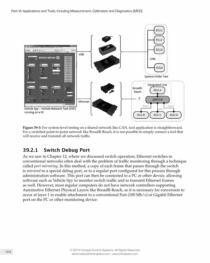
1016
Part VI: Applications and Tools, Including Measurement, Calibration and Diagnostics (MCD)
© 2014 Intrepid Control Systems. All Rights Reserved. [email protected] • www.intrepidcs.com
Figure 39-3: For system-level testing on a shared network like CAN, tool application is straightforward. For a switched point-to-point network like BroadR-Reach, it is not possible to simply connect a tool that will receive and transmit all network traffic.
39.2.1 Switch Debug Port As we saw in Chapter 12, where we discussed switch operation, Ethernet switches in conventional networks often deal with the problem of traffic monitoring through a technique called port mirroring. In this method, a copy of each frame that passes through the switch is mirrored to a special debug port, or to a regular port configured for this process through administration software. This port can then be connected to a PC or other device, allowing software such as Vehicle Spy to monitor switch traffic and to transmit Ethernet frames as well. However, most regular computers do not have network controllers supporting Automotive Ethernet Physical Layers like BroadR-Reach, so it is necessary for conversion to occur at layer 1 to enable attachment to a conventional Fast (100 Mb/s) or Gigabit Ethernet port on the PC or other monitoring device.

1017
Chapter 39: Automotive Ethernet Tool Applications
© 2014 Intrepid Control Systems. All Rights Reserved. [email protected] • www.intrepidcs.com
Figure 39-4: If a switch has an extra port available, it is possible to use the port for debugging through a method called port mirroring. However, there are drawbacks to this method, so port mirroring is not always advisable for Automotive Ethernet testing.
At first, port mirroring seems like a great, all-encompassing method for testing and simulating Automotive Ethernet networks. However, there are important drawbacks to this approach:
1. Any bad Ethernet frames that are transmitted on the network will be dropped by the switch and not forwarded through the debug port. With this method, the test tool will never be able to detect bad frames.
2. In order to monitor all frames from all ports, it is necessary for multiple ports to forward frames to a single debug port. Unless the debug port is an order of magnitude faster than the normal ports, there is a chance that an overflow may occur, where the buffer for that port fills up and additional frames must be discarded. Again, this means these frames will never be seen by the user of the test software.
3. The simple existence of a debug port adds cost to the system. It is necessary to have a physical connector that is accessible to the test tool, and all associated Physical Layer chips and connections on a board must be provided. Car companies are reluctant to add hardware to a production vehicle solely for the purpose of debugging.
4. Port mirroring doesn’t help with some common use cases involving the transmission of Ethernet frames from the test tool to the rest of the network. All Ethernet frames require a source MAC address; if the address of the PC is used to transmit, the nodes will not recognize it. It is not possible for the test tool to clone a MAC address that already exists on the network, because two identical MAC addresses are not allowable on the same LAN.
5. Activating functionality inside a DUT specifically for test and measurement purposes has an effect on the DUT, which is something generally to be avoided.

1018
Part VI: Applications and Tools, Including Measurement, Calibration and Diagnostics (MCD)
© 2014 Intrepid Control Systems. All Rights Reserved. [email protected] • www.intrepidcs.com
39.2.2 Single Active TAP – RAD-StarAn alternative to the debug port is to make use of an active TAP, devices which have long been used to develop and test Ethernet networks. An active TAP, such as the RAD-Star, is a device that is inserted into a leg of an Ethernet network to provide access to the network for testing: thus the name “TAP”, which stands for “test access point”. It must be understood that the TAP is not simply connected to the physical wires of the network. Rather it is inserted, meaning that the wires connecting the TAP to the switch (Port 1 in Figure 39-5) are physically separated from the wires connecting the TAP to the Ethernet node (Port 1’). The TAP will transfer all Ethernet frames from Port 1 to Port 1’ and all frames from Port 1’ to Port 1 with very low latency. These frames will also be copied to a normal Ethernet port on the TAP (labelled “Ethernet” in the figure) so that a PC running a test tool can monitor them. The PC can also transmit Ethernet frames through the TAP.
Note: The term “TAP” is used in the industry to refer to both the actual test access points (the interfaces between switches and nodes)
and the hardware used to implement this functionality (like the RAD-Star).
Figure 39-5: A diagram of a system under test that uses a single active TAP device (RAD-Star). The RAD-Star, in combination with Vehicle Spy, makes it possible for bad frames to be captured and presented to the user for analysis.

1019
Chapter 39: Automotive Ethernet Tool Applications
© 2014 Intrepid Control Systems. All Rights Reserved. [email protected] • www.intrepidcs.com
An active TAP has two primary advantages over the port mirroring method:
1. The RAD-Star can detect a bad Ethernet Frame and encapsulate it into a new frame, then forward it to the PC via the standard Ethernet port. Vehicle Spy can then unwrap the bad frame so it can be analyzed.
2. The combination of Vehicle Spy with an active TAP can enable the PC to transmit Ethernet frames with the same MAC address as the Node to which it is attached. In this way, it is possible to simulate Ethernet traffic on the network without introducing a foreign address.
The two main drawbacks of this method are the need to insert it into the network, and the latency introduced by copying an Ethernet frame from one port to another, which is on the order of 2 µs.
39.2.3 Multi-Active TAP - RAD-GalaxyA multi-active TAP has the same basic advantages and disadvantages as a single active TAP, but with the added advantage that it can monitor and time-align frames from numerous ports of an Automotive Ethernet switch. The RAD-Galaxy product can support up to 6 switch ports, and can time-align all frames between the ports to an accuracy of 25 ns, giving the user the ability to accurately monitor incoming and outgoing frames from the switch and test its latencies.
Figure 39-6: The RAD-Galaxy has the same capabilities as the RAD-Star, but offers 6 active TAPs and the ability to time-align network data among them.
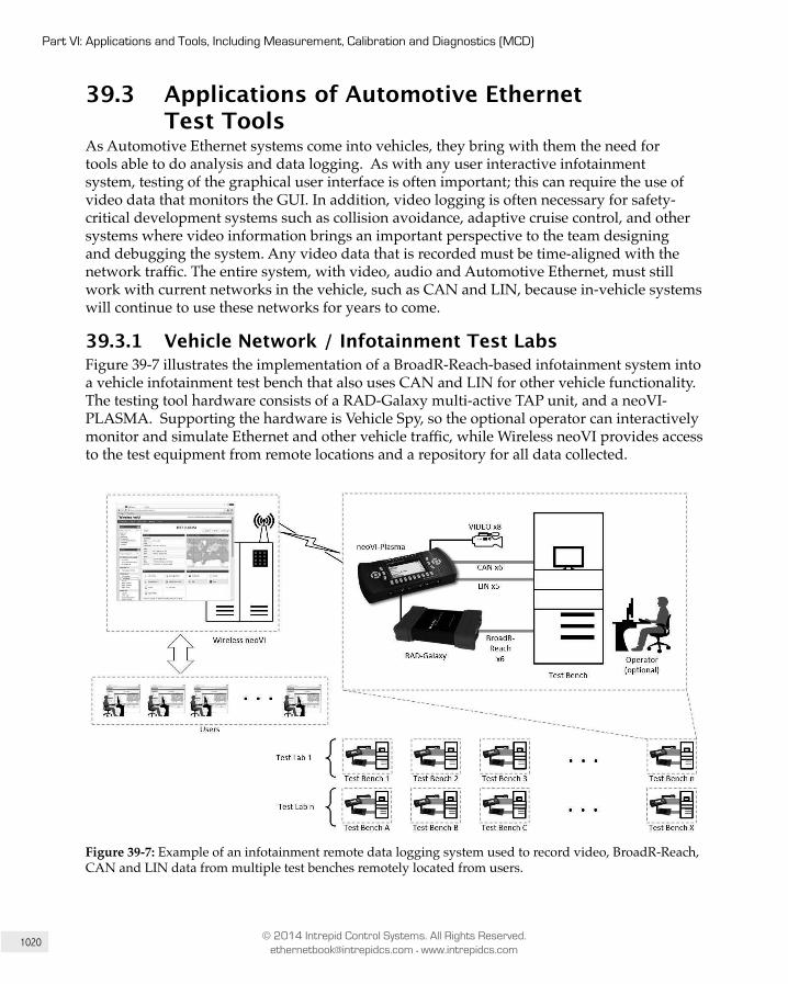
1020
Part VI: Applications and Tools, Including Measurement, Calibration and Diagnostics (MCD)
© 2014 Intrepid Control Systems. All Rights Reserved. [email protected] • www.intrepidcs.com
39.3 Applications of Automotive Ethernet Test Tools
As Automotive Ethernet systems come into vehicles, they bring with them the need for tools able to do analysis and data logging. As with any user interactive infotainment system, testing of the graphical user interface is often important; this can require the use of video data that monitors the GUI. In addition, video logging is often necessary for safety-critical development systems such as collision avoidance, adaptive cruise control, and other systems where video information brings an important perspective to the team designing and debugging the system. Any video data that is recorded must be time-aligned with the network traffic. The entire system, with video, audio and Automotive Ethernet, must still work with current networks in the vehicle, such as CAN and LIN, because in-vehicle systems will continue to use these networks for years to come.
39.3.1 Vehicle Network / Infotainment Test LabsFigure 39-7 illustrates the implementation of a BroadR-Reach-based infotainment system into a vehicle infotainment test bench that also uses CAN and LIN for other vehicle functionality. The testing tool hardware consists of a RAD-Galaxy multi-active TAP unit, and a neoVI-PLASMA. Supporting the hardware is Vehicle Spy, so the optional operator can interactively monitor and simulate Ethernet and other vehicle traffic, while Wireless neoVI provides access to the test equipment from remote locations and a repository for all data collected.
Figure 39-7: Example of an infotainment remote data logging system used to record video, BroadR-Reach, CAN and LIN data from multiple test benches remotely located from users.
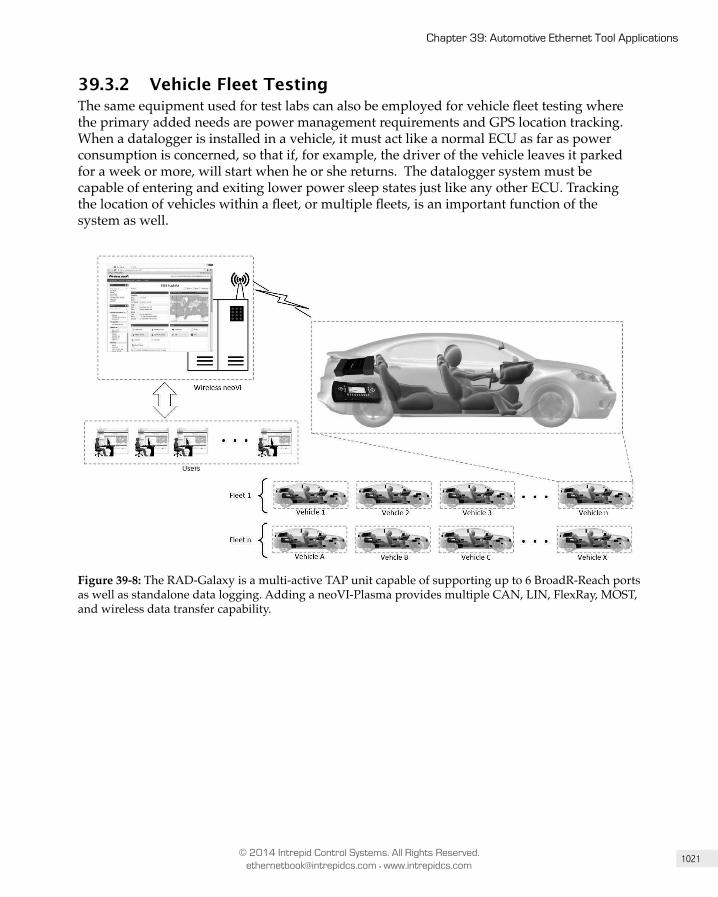
1021
Chapter 39: Automotive Ethernet Tool Applications
© 2014 Intrepid Control Systems. All Rights Reserved. [email protected] • www.intrepidcs.com
39.3.2 Vehicle Fleet TestingThe same equipment used for test labs can also be employed for vehicle fleet testing where the primary added needs are power management requirements and GPS location tracking. When a datalogger is installed in a vehicle, it must act like a normal ECU as far as power consumption is concerned, so that if, for example, the driver of the vehicle leaves it parked for a week or more, will start when he or she returns. The datalogger system must be capable of entering and exiting lower power sleep states just like any other ECU. Tracking the location of vehicles within a fleet, or multiple fleets, is an important function of the system as well.
Figure 39-8: The RAD-Galaxy is a multi-active TAP unit capable of supporting up to 6 BroadR-Reach ports as well as standalone data logging. Adding a neoVI-Plasma provides multiple CAN, LIN, FlexRay, MOST, and wireless data transfer capability.
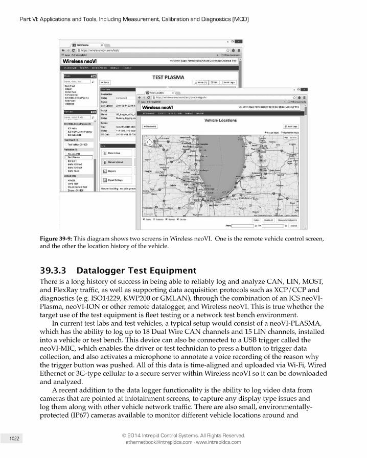
1022
Part VI: Applications and Tools, Including Measurement, Calibration and Diagnostics (MCD)
© 2014 Intrepid Control Systems. All Rights Reserved. [email protected] • www.intrepidcs.com
Figure 39-9: This diagram shows two screens in Wireless neoVI. One is the remote vehicle control screen, and the other the location history of the vehicle.
39.3.3 Datalogger Test EquipmentThere is a long history of success in being able to reliably log and analyze CAN, LIN, MOST, and FlexRay traffic, as well as supporting data acquisition protocols such as XCP/CCP and diagnostics (e.g. ISO14229, KWP200 or GMLAN), through the combination of an ICS neoVI-Plasma, neoVI-ION or other remote datalogger, and Wireless neoVI. This is true whether the target use of the test equipment is fleet testing or a network test bench environment.
In current test labs and test vehicles, a typical setup would consist of a neoVI-PLASMA, which has the ability to log up to 18 Dual Wire CAN channels and 15 LIN channels, installed into a vehicle or test bench. This device can also be connected to a USB trigger called the neoVI-MIC, which enables the driver or test technician to press a button to trigger data collection, and also activates a microphone to annotate a voice recording of the reason why the trigger button was pushed. All of this data is time-aligned and uploaded via Wi-Fi, Wired Ethernet or 3G-type cellular to a secure server within Wireless neoVI so it can be downloaded and analyzed.
A recent addition to the data logger functionality is the ability to log video data from cameras that are pointed at infotainment screens, to capture any display type issues and log them along with other vehicle network traffic. There are also small, environmentally-protected (IP67) cameras available to monitor different vehicle locations around and
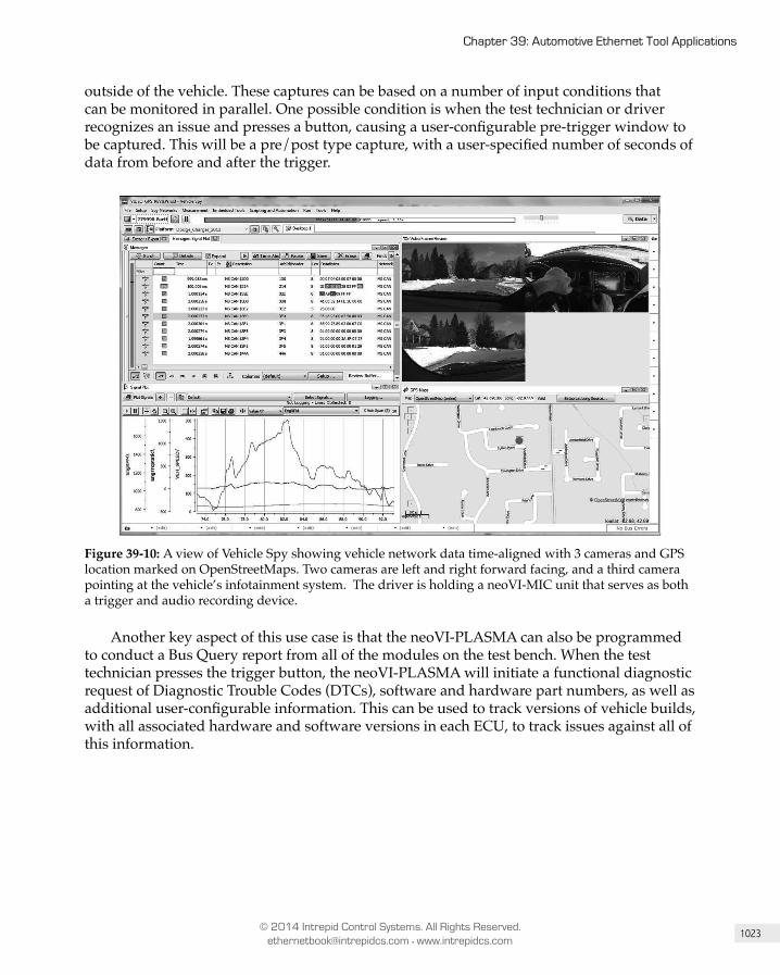
1023
Chapter 39: Automotive Ethernet Tool Applications
© 2014 Intrepid Control Systems. All Rights Reserved. [email protected] • www.intrepidcs.com
outside of the vehicle. These captures can be based on a number of input conditions that can be monitored in parallel. One possible condition is when the test technician or driver recognizes an issue and presses a button, causing a user-configurable pre-trigger window to be captured. This will be a pre/post type capture, with a user-specified number of seconds of data from before and after the trigger.
Figure 39-10: A view of Vehicle Spy showing vehicle network data time-aligned with 3 cameras and GPS location marked on OpenStreetMaps. Two cameras are left and right forward facing, and a third camera pointing at the vehicle’s infotainment system. The driver is holding a neoVI-MIC unit that serves as both a trigger and audio recording device.
Another key aspect of this use case is that the neoVI-PLASMA can also be programmed to conduct a Bus Query report from all of the modules on the test bench. When the test technician presses the trigger button, the neoVI-PLASMA will initiate a functional diagnostic request of Diagnostic Trouble Codes (DTCs), software and hardware part numbers, as well as additional user-configurable information. This can be used to track versions of vehicle builds, with all associated hardware and software versions in each ECU, to track issues against all of this information.

1024
Part VI: Applications and Tools, Including Measurement, Calibration and Diagnostics (MCD)
© 2014 Intrepid Control Systems. All Rights Reserved. [email protected] • www.intrepidcs.com
Figure 39-11: Example of a Bus Query report from a single vehicle. These reports can track DTCs as well as software and hardware part numbers.
The Ethernet traffic will be monitored using a RAD-Galaxy, which as mentioned earlier, will connect to the BroadR-Reach lines on the test bench or vehicle. Using a high-speed Ethernet connection to the neoVI-PLASMA, traffic from the test bench or vehicle’s BroadR-Reach networks can be routed to the neoVI-PLASMA for logging when the trigger is pressed.
All of this data is stored on an SD card that is in the neoVI-PLASMA, which is also always connected to a Wi-Fi, wired Ethernet or 3G network that has access to the Wireless neoVI server over a secured and encrypted connection. Based on the user’s setup, whenever the test technician or driver presses the trigger button to capture data, it will then be immediately uploaded to the Wireless neoVI server. At this point the server also will send email notifications to any responsible engineers, to alert them that a trigger has been set and data is ready to be analyzed.

1025
Chapter 39: Automotive Ethernet Tool Applications
© 2014 Intrepid Control Systems. All Rights Reserved. [email protected] • www.intrepidcs.com
Once the user logs into the Wireless neoVI website, they will be able to locate the test bench or vehicle and view its location, ID number or VIN, and view and historical reports of DTCs. They will also have a data archive full of captures, which can be obtained in several industry standard formats. Using these files, the user will have the ability to view signal data directly on the website and also plot signals.
For a more in-depth look at message data, the user may choose to download the data file and analyze it using ICS’s Vehicle Spy 3 software. With this software the user will be able to view all of the CAN, LIN, Ethernet, and video capture data on one screen, with everything time-aligned using 25ns timestamps. The user can also see the exact moment that the test operator pressed the trigger button, and the window of data from the pre/post condition; they can load database files such as .dbc, .ldf, and .arxml files to decode the data and view signal data as well. Numerous industry standard data file formats can be automatically exported, so the data can be used in nearly any data analysis package.
Figure 39-12: Data collected from Intrepid’s dataloggers can be converted to nearly any industry standard format.
39.4 ConclusionProducts from Intrepid Control Systems provide the automotive industry with the ability to implement an all-in-one solution for their new Ethernet-based network systems. They can have a central tool that handles all functions of the vehicle, and a single location where all of their project data is stored to facilitate data sharing across the business. This solution allows issues to be tracked down and fixes developed before their products are delivered to customers, preventing very important quality issues from arising, and more importantly, preventing recalls. Infotainment is typically the largest area of customer complaints, and by being proactive in utilizing ICS product technology, our customers are able to bring a higher-quality product to market.
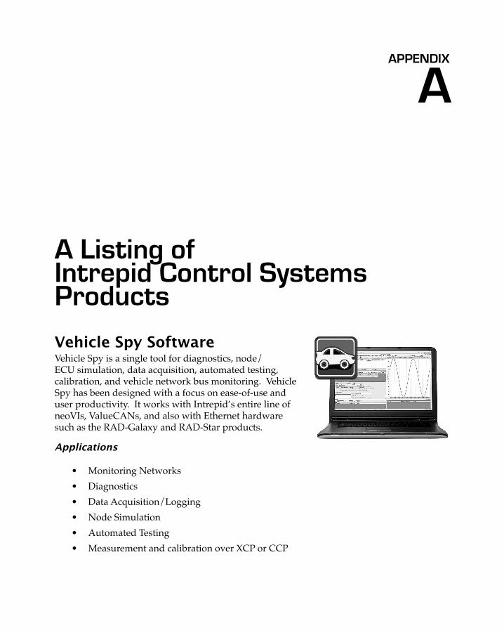
APPENDIX
A Listing of Intrepid Control Systems Products
Vehicle Spy SoftwareVehicle Spy is a single tool for diagnostics, node/ECU simulation, data acquisition, automated testing, calibration, and vehicle network bus monitoring. Vehicle Spy has been designed with a focus on ease-of-use and user productivity. It works with Intrepid’s entire line of neoVIs, ValueCANs, and also with Ethernet hardware such as the RAD-Galaxy and RAD-Star products.
Applications
• Monitoring Networks• Diagnostics• Data Acquisition/Logging• Node Simulation• Automated Testing • Measurement and calibration over XCP or CCP
A
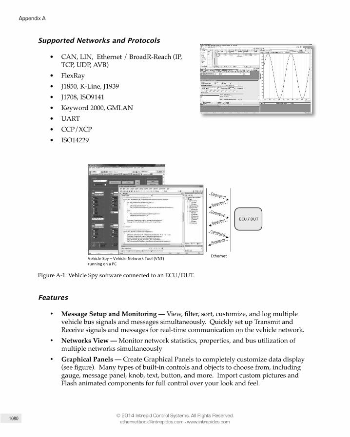
1080
Appendix A
© 2014 Intrepid Control Systems. All Rights Reserved. [email protected] • www.intrepidcs.com
Supported Networks and Protocols
• CAN, LIN, Ethernet / BroadR-Reach (IP, TCP, UDP, AVB)
• FlexRay• J1850, K-Line, J1939• J1708, ISO9141• Keyword 2000, GMLAN• UART• CCP/XCP• ISO14229
ECU / DUT
EthernetVehicle Spy – Vehicle Network Tool (VNT) running on a PC
Figure A-1: Vehicle Spy software connected to an ECU/DUT.
Features
• Message Setup and Monitoring — View, filter, sort, customize, and log multiple vehicle bus signals and messages simultaneously. Quickly set up Transmit and Receive signals and messages for real-time communication on the vehicle network.
• Networks View — Monitor network statistics, properties, and bus utilization of multiple networks simultaneously
• Graphical Panels — Create Graphical Panels to completely customize data display (see figure). Many types of built-in controls and objects to choose from, including gauge, message panel, knob, text, button, and more. Import custom pictures and Flash animated components for full control over your look and feel.

1081
A Listing of Intrepid Control Systems Products
© 2014 Intrepid Control Systems. All Rights Reserved. [email protected] • www.intrepidcs.com
Figure A-2: Using a drag-and-drop interface, you can create customized graphical panels in Vehicle Spy to monitor test vehicles, transmit messages on a vehicle network, and tackle a wide range of other applications.
Data Analysis — Post-analysis plotting includes multi-Y axis, multi-X axis, data file overlay, legends, copy to clipboard, multiple cursors, and much more.
• Scripting and Automation —
• Function Blocks — Easily set up automated tasks, create test procedures, and simulate nodes/ECUs without relying on a complicated, text-based computer language.
• C Code Interface — Use ANSI standard C Code via Visual Studio Express. This interface allows you access to anything accessible through Visual C, including security DLLs, external hardware, or Win32API and interfaces.
• Data Logging and Scripting —
• VehicleScape DAQ — Automatically generate scripts with sleep modes, multiple triggers, and save data to the cloud or on the neoVI’s SD Card. VehicleScape provides an intuitive interface. Extract and export to many popular file formats.
• Stand-Alone Simulators and Gateways — Make powerful hand held ECU flashers, diagnostics tools and data loggers with the neoVI. Program all of these functions with Function Block scripts created in Vehicle Spy 3.
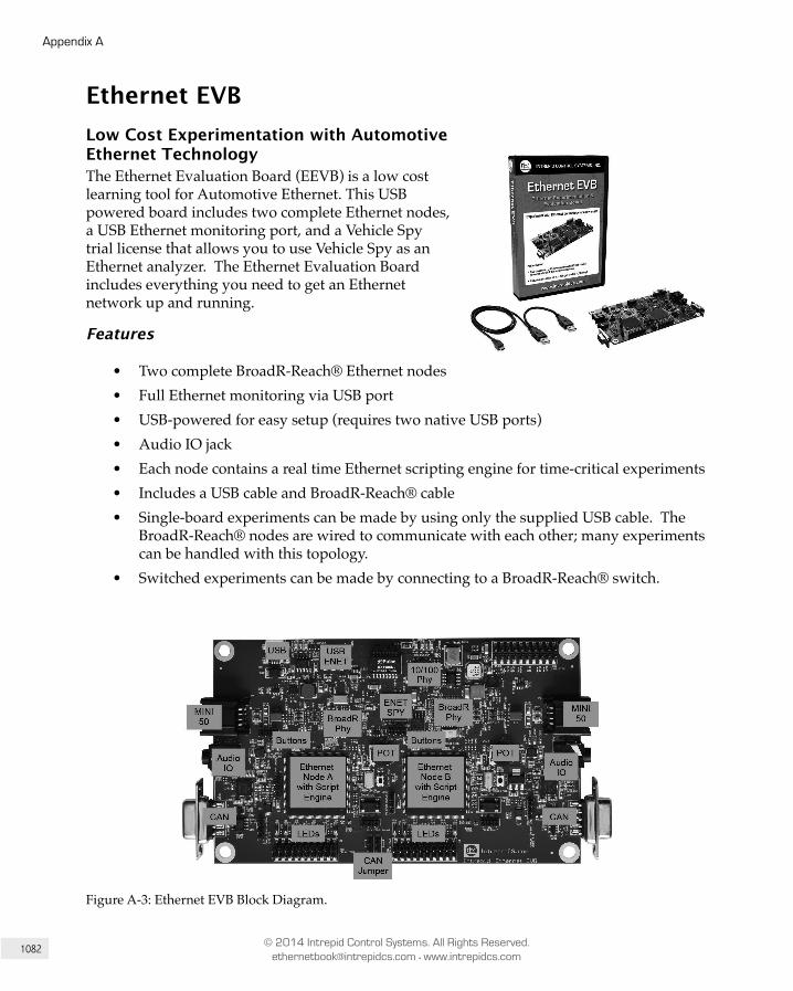
1082
Appendix A
© 2014 Intrepid Control Systems. All Rights Reserved. [email protected] • www.intrepidcs.com
Ethernet EVBLow Cost Experimentation with Automotive Ethernet TechnologyThe Ethernet Evaluation Board (EEVB) is a low cost learning tool for Automotive Ethernet. This USB powered board includes two complete Ethernet nodes, a USB Ethernet monitoring port, and a Vehicle Spy trial license that allows you to use Vehicle Spy as an Ethernet analyzer. The Ethernet Evaluation Board includes everything you need to get an Ethernet network up and running.
Features
• Two complete BroadR-Reach® Ethernet nodes• Full Ethernet monitoring via USB port• USB-powered for easy setup (requires two native USB ports)• Audio IO jack• Each node contains a real time Ethernet scripting engine for time-critical experiments• Includes a USB cable and BroadR-Reach® cable• Single-board experiments can be made by using only the supplied USB cable. The
BroadR-Reach® nodes are wired to communicate with each other; many experiments can be handled with this topology.
• Switched experiments can be made by connecting to a BroadR-Reach® switch.
Figure A-3: Ethernet EVB Block Diagram.
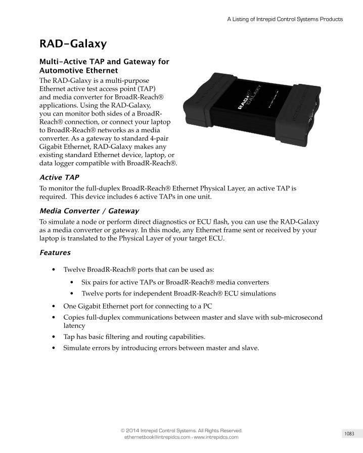
1083
A Listing of Intrepid Control Systems Products
© 2014 Intrepid Control Systems. All Rights Reserved. [email protected] • www.intrepidcs.com
RAD-GalaxyMulti-Active TAP and Gateway for Automotive EthernetThe RAD-Galaxy is a multi-purpose Ethernet active test access point (TAP) and media converter for BroadR-Reach® applications. Using the RAD-Galaxy, you can monitor both sides of a BroadR-Reach® connection, or connect your laptop to BroadR-Reach® networks as a media converter. As a gateway to standard 4-pair Gigabit Ethernet, RAD-Galaxy makes any existing standard Ethernet device, laptop, or data logger compatible with BroadR-Reach®.
Active TAPTo monitor the full-duplex BroadR-Reach® Ethernet Physical Layer, an active TAP is required. This device includes 6 active TAPs in one unit.
Media Converter / GatewayTo simulate a node or perform direct diagnostics or ECU flash, you can use the RAD-Galaxy as a media converter or gateway. In this mode, any Ethernet frame sent or received by your laptop is translated to the Physical Layer of your target ECU.
Features
• Twelve BroadR-Reach® ports that can be used as:
• Six pairs for active TAPs or BroadR-Reach® media converters• Twelve ports for independent BroadR-Reach® ECU simulations
• One Gigabit Ethernet port for connecting to a PC• Copies full-duplex communications between master and slave with sub-microsecond
latency• Tap has basic filtering and routing capabilities.• Simulate errors by introducing errors between master and slave.
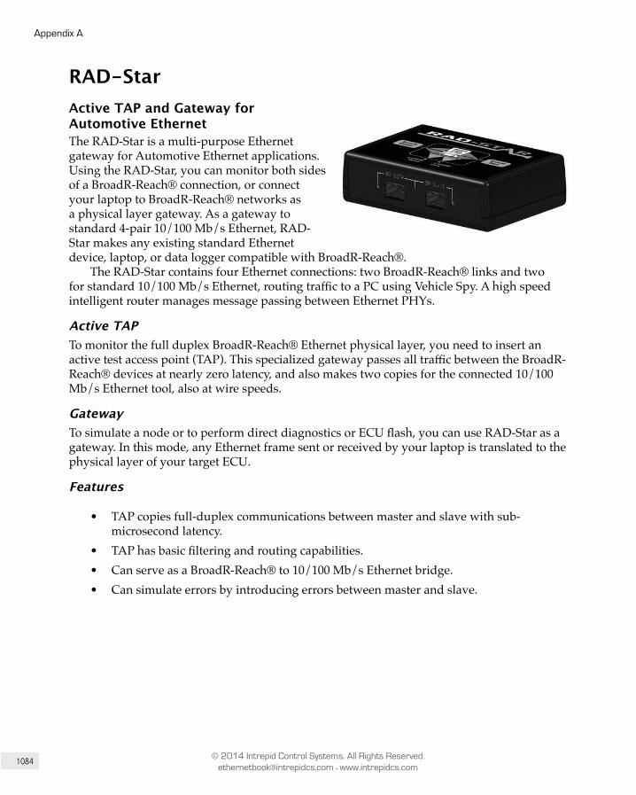
1084
Appendix A
© 2014 Intrepid Control Systems. All Rights Reserved. [email protected] • www.intrepidcs.com
RAD-StarActive TAP and Gateway for Automotive EthernetThe RAD-Star is a multi-purpose Ethernet gateway for Automotive Ethernet applications. Using the RAD-Star, you can monitor both sides of a BroadR-Reach® connection, or connect your laptop to BroadR-Reach® networks as a physical layer gateway. As a gateway to standard 4-pair 10/100 Mb/s Ethernet, RAD-Star makes any existing standard Ethernet device, laptop, or data logger compatible with BroadR-Reach®.
The RAD-Star contains four Ethernet connections: two BroadR-Reach® links and two for standard 10/100 Mb/s Ethernet, routing traffic to a PC using Vehicle Spy. A high speed intelligent router manages message passing between Ethernet PHYs.
Active TAPTo monitor the full duplex BroadR-Reach® Ethernet physical layer, you need to insert an active test access point (TAP). This specialized gateway passes all traffic between the BroadR-Reach® devices at nearly zero latency, and also makes two copies for the connected 10/100 Mb/s Ethernet tool, also at wire speeds.
GatewayTo simulate a node or to perform direct diagnostics or ECU flash, you can use RAD-Star as a gateway. In this mode, any Ethernet frame sent or received by your laptop is translated to the physical layer of your target ECU.
Features
• TAP copies full-duplex communications between master and slave with sub-microsecond latency.
• TAP has basic filtering and routing capabilities.• Can serve as a BroadR-Reach® to 10/100 Mb/s Ethernet bridge.• Can simulate errors by introducing errors between master and slave.
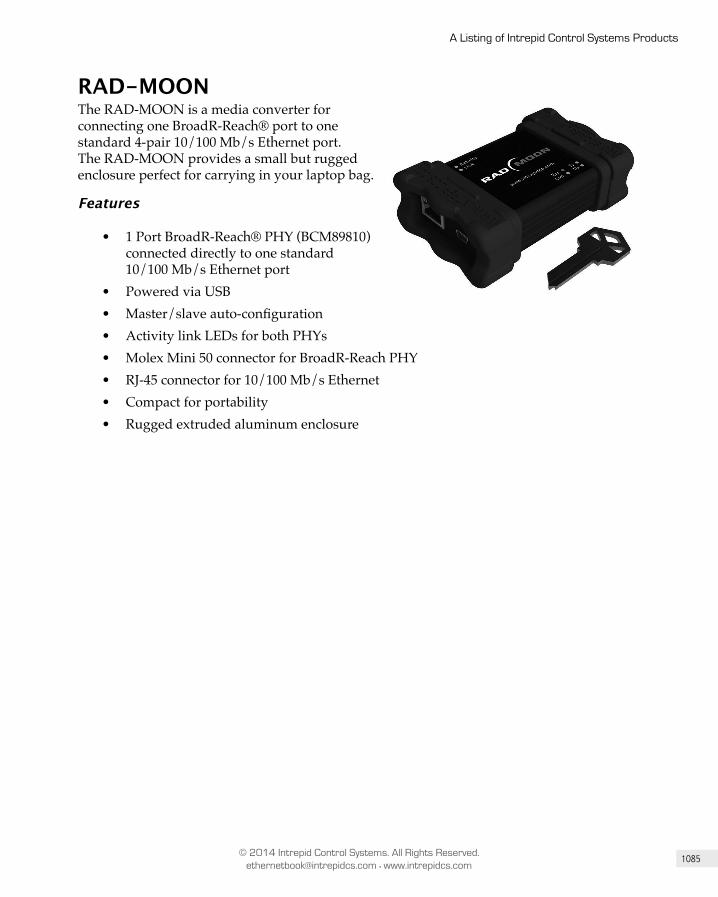
1085
A Listing of Intrepid Control Systems Products
© 2014 Intrepid Control Systems. All Rights Reserved. [email protected] • www.intrepidcs.com
RAD-MOONThe RAD-MOON is a media converter for connecting one BroadR-Reach® port to one standard 4-pair 10/100 Mb/s Ethernet port. The RAD-MOON provides a small but rugged enclosure perfect for carrying in your laptop bag.
Features
• 1 Port BroadR-Reach® PHY (BCM89810) connected directly to one standard 10/100 Mb/s Ethernet port
• Powered via USB• Master/slave auto-configuration• Activity link LEDs for both PHYs• Molex Mini 50 connector for BroadR-Reach PHY• RJ-45 connector for 10/100 Mb/s Ethernet• Compact for portability• Rugged extruded aluminum enclosure
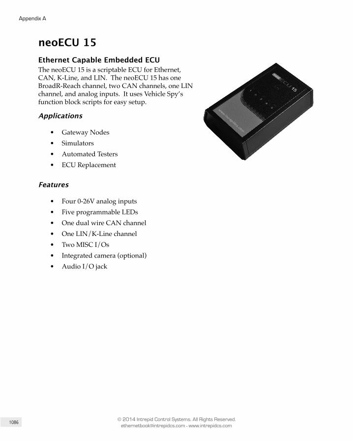
1086
Appendix A
© 2014 Intrepid Control Systems. All Rights Reserved. [email protected] • www.intrepidcs.com
neoECU 15Ethernet Capable Embedded ECUThe neoECU 15 is a scriptable ECU for Ethernet, CAN, K-Line, and LIN. The neoECU 15 has one BroadR-Reach channel, two CAN channels, one LIN channel, and analog inputs. It uses Vehicle Spy’s function block scripts for easy setup.
Applications
• Gateway Nodes• Simulators• Automated Testers• ECU Replacement
Features
• Four 0-26V analog inputs• Five programmable LEDs• One dual wire CAN channel• One LIN/K-Line channel• Two MISC I/Os• Integrated camera (optional)• Audio I/O jack
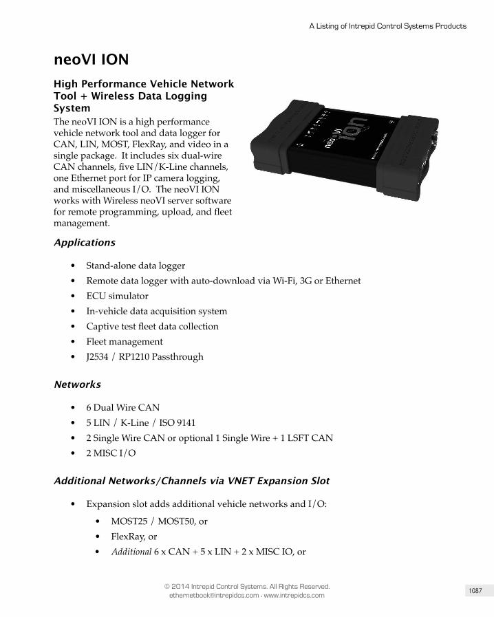
1087
A Listing of Intrepid Control Systems Products
© 2014 Intrepid Control Systems. All Rights Reserved. [email protected] • www.intrepidcs.com
neoVI IONHigh Performance Vehicle Network Tool + Wireless Data Logging SystemThe neoVI ION is a high performance vehicle network tool and data logger for CAN, LIN, MOST, FlexRay, and video in a single package. It includes six dual-wire CAN channels, five LIN/K-Line channels, one Ethernet port for IP camera logging, and miscellaneous I/O. The neoVI ION works with Wireless neoVI server software for remote programming, upload, and fleet management.
Applications
• Stand-alone data logger• Remote data logger with auto-download via Wi-Fi, 3G or Ethernet• ECU simulator• In-vehicle data acquisition system• Captive test fleet data collection• Fleet management• J2534 / RP1210 Passthrough
Networks
• 6 Dual Wire CAN• 5 LIN / K-Line / ISO 9141• 2 Single Wire CAN or optional 1 Single Wire + 1 LSFT CAN• 2 MISC I/O
Additional Networks/Channels via VNET Expansion Slot
• Expansion slot adds additional vehicle networks and I/O:
• MOST25 / MOST50, or• FlexRay, or• Additional 6 x CAN + 5 x LIN + 2 x MISC IO, or

1088
Appendix A
© 2014 Intrepid Control Systems. All Rights Reserved. [email protected] • www.intrepidcs.com
• Additional 9 channels analog input
Features
• 32 GB SD Card (expandable to 128 GB)• 5 Hz GPS• Internal 3G/4G modem• 10/100 Ethernet LAN port for data upload or connection to external modem• 10/100 Ethernet DAQ port for AXIS IP Camera or other DAQ uses• Several sleep and upload options• Configurable with Vehicle Spy’s VehicleScape DAQ script generator
• Able to get data and manage fleet via wireless neoVI• Supports Vehicle Spy’s function blocks and custom scripting for advanced functions
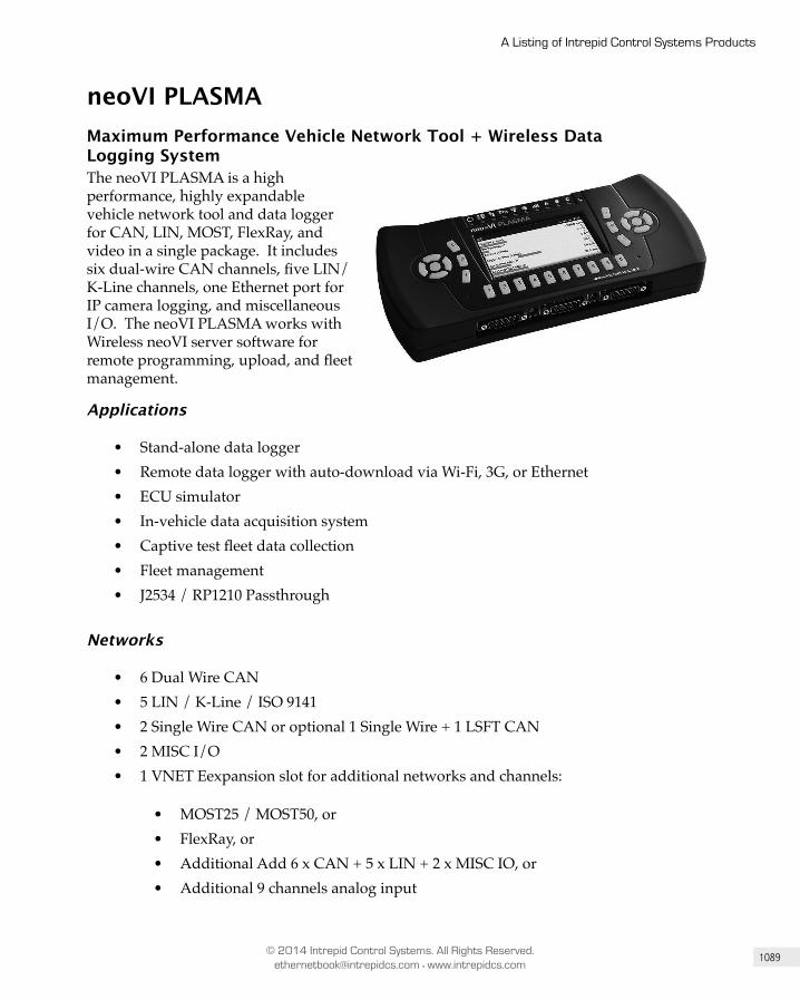
1089
A Listing of Intrepid Control Systems Products
© 2014 Intrepid Control Systems. All Rights Reserved. [email protected] • www.intrepidcs.com
neoVI PLASMAMaximum Performance Vehicle Network Tool + Wireless Data Logging SystemThe neoVI PLASMA is a high performance, highly expandable vehicle network tool and data logger for CAN, LIN, MOST, FlexRay, and video in a single package. It includes six dual-wire CAN channels, five LIN/K-Line channels, one Ethernet port for IP camera logging, and miscellaneous I/O. The neoVI PLASMA works with Wireless neoVI server software for remote programming, upload, and fleet management.
Applications
• Stand-alone data logger• Remote data logger with auto-download via Wi-Fi, 3G, or Ethernet• ECU simulator• In-vehicle data acquisition system• Captive test fleet data collection• Fleet management• J2534 / RP1210 Passthrough
Networks
• 6 Dual Wire CAN• 5 LIN / K-Line / ISO 9141• 2 Single Wire CAN or optional 1 Single Wire + 1 LSFT CAN• 2 MISC I/O• 1 VNET Eexpansion slot for additional networks and channels:
• MOST25 / MOST50, or• FlexRay, or• Additional Add 6 x CAN + 5 x LIN + 2 x MISC IO, or• Additional 9 channels analog input
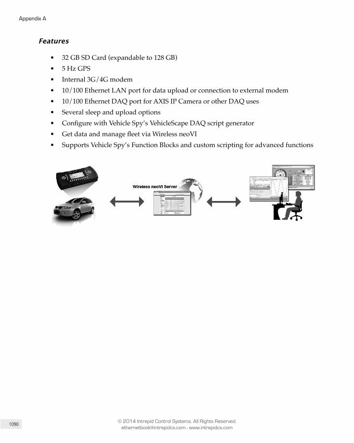
1090
Appendix A
© 2014 Intrepid Control Systems. All Rights Reserved. [email protected] • www.intrepidcs.com
Features
• 32 GB SD Card (expandable to 128 GB)• 5 Hz GPS• Internal 3G/4G modem• 10/100 Ethernet LAN port for data upload or connection to external modem• 10/100 Ethernet DAQ port for AXIS IP Camera or other DAQ uses• Several sleep and upload options• Configure with Vehicle Spy’s VehicleScape DAQ script generator• Get data and manage fleet via Wireless neoVI• Supports Vehicle Spy’s Function Blocks and custom scripting for advanced functions
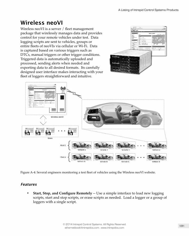
1091
A Listing of Intrepid Control Systems Products
© 2014 Intrepid Control Systems. All Rights Reserved. [email protected] • www.intrepidcs.com
Wireless neoVIWireless neoVI is a server / fleet management package that wirelessly manages data and provides control for your remote vehicles under test. Data logging scripts are sent to vehicles, groups or entire fleets of neoVIs via cellular or Wi-Fi. Data is captured based on various triggers such as DTCs, manual triggers or other trigger conditions. Triggered data is automatically uploaded and processed, sending alerts when needed and exporting data to all desired formats. Its carefully designed user interface makes interacting with your fleet of loggers straightforward and intuitive.
Figure A-4: Several engineers monitoring a test fleet of vehicles using the Wireless neoVI website.
Features
• Start, Stop, and Configure Remotely -- Use a simple interface to load new logging scripts, start and stop scripts, or erase scripts as needed. Load a logger or a group of loggers with a single script.

1092
Appendix A
© 2014 Intrepid Control Systems. All Rights Reserved. [email protected] • www.intrepidcs.com
• E-mail notifications – When a trigger or event occurs anywhere in the world on a specific vehicle or set of vehicles, a list of users is automatically e-mailed. Inside the e-mail is information about the events as well as links directly to the data.
• Gather Data Automatically -- Multiple triggers based on any trigger condition including DTCs and manual triggers. Send data on each trigger. Data is compressed 30-100x to minimize data usage on your carrier of choice.
• Automatically Extract and Export Data -- Data formats and reports include custom CSV files, industry-standard bus captures (VSB, CSV, LOG, ASC), industry-standard signal captures (MAT, MDF, DAT, CSV), and custom reports (PRN files from WinValid, Bus Query Reports).
• Secure, Redundant, and Reliable -- Secure Socket Layer (SSL) or Transport Layer Security (TLS). Your data is safeguarded at all times, from device to server and web browser to web portal. Our distributed server architecture will seamlessly switch to another without interruption or “downtime”.
• Manage Your Fleet -- Automated and on-demand reporting, dynamic issues management, and vehicle management
• Track Your Fleet -- Geofencing, location reporting, and historical GPS reports.• Live Data Signal Plotting -- Drag and drop signals onto graphs for up to five signal
plots. Data Analysis online using MDF files. JBEAM Integration available• Choice of Servers: Use Intrepid’s Servers or your own on-premise
Figure A-5: Among other useful views, the Wireless neoVI website lets you view your test fleet’s driving history and statistics on a map.
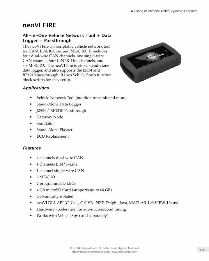
1093
A Listing of Intrepid Control Systems Products
© 2014 Intrepid Control Systems. All Rights Reserved. [email protected] • www.intrepidcs.com
neoVI FIREAll-in-One Vehicle Network Tool + Data Logger + PassthroughThe neoVI Fire is a scriptable vehicle network tool for CAN, LIN, K-Line, and MISC IO. It includes four dual-wire CAN channels, one single-wire CAN channel, four LIN/K-Line channels, and six MISC IO. The neoVI Fire is also a stand-alone data logger, and also supports the J2534 and RP1210 passthrough. It uses Vehicle Spy’s function block scripts for easy setup.
Applications
• Vehicle Network Tool (monitor, transmit and more)• Stand-Alone Data Logger• J2534 / RP1210 Passthrough• Gateway Node• Simulator• Stand-Alone Flasher• ECU Replacement
Features
• 4 channels dual-wire CAN• 4 channels LIN/K-Line• 1 channel single-wire CAN• 6 MISC IO• 2 programmable LEDs• 4 GB microSD Card (supports up to 64 GB)• Galvanically isolated• neoVI DLL API (C, C++, C#, VB, .NET, Delphi, Java, MATLAB, LabVIEW, Linux)• Hardware acceleration for sub-microsecond timing• Works with Vehicle Spy (sold separately)

1094
Appendix A
© 2014 Intrepid Control Systems. All Rights Reserved. [email protected] • www.intrepidcs.com
ValueCAN3Low Cost, High Value, Field Tested: Over 20,000 Sold Worldwide!The ValueCAN3 is a low cost, high performance, high quality vehicle network tool for CAN. It includes two dual-wire CAN channels. Although the ValueCAN3 is low cost, it is galvanically isolated and is scriptable, features normally found only in much more expensive network tools. The ValueCAN3 also supports J2534 and RP1210 passthrough. It uses Vehicle Spy’s function block scripts for easy setup of scripting.
Applications
• Vehicle Network Tool (monitor, transmit and more)• J2534 / RP1210 Passthrough• Gateway Node• Simulator
Features
• 2 channels dual-wire CAN• Galvanically isolated• neoVI DLL API (C, C++, C#, VB, .NET, Delphi, Java, MATLAB, LabVIEW, Linux)• Hardware acceleration for sub-microsecond timing• Works with Vehicle Spy (sold separately)
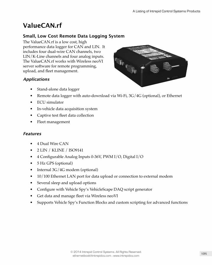
1095
A Listing of Intrepid Control Systems Products
© 2014 Intrepid Control Systems. All Rights Reserved. [email protected] • www.intrepidcs.com
ValueCAN.rfSmall, Low Co st Remote Data Logging SystemThe ValueCAN.rf is a low cost, high performance data logger for CAN and LIN. It includes four dual-wire CAN channels, two LIN/K-Line channels and four analog inputs. The ValueCAN.rf works with Wireless neoVI server software for remote programming, upload, and fleet management.
Applications
• Stand-alone data logger• Remote data logger with auto-download via Wi-Fi, 3G/4G (optional), or Ethernet• ECU simulator• In-vehicle data acquisition system• Captive test fleet data collection• Fleet management
Features
• 4 Dual Wire CAN• 2 LIN / KLINE / ISO9141• 4 Configurable Analog Inputs 0-36V, PWM I/O, Digital I/O• 5 Hz GPS (optional)• Internal 3G/4G modem (optional)• 10/100 Ethernet LAN port for data upload or connection to external modem• Several sleep and upload options• Configure with Vehicle Spy’s VehicleScape DAQ script generator• Get data and manage fleet via Wireless neoVI• Supports Vehicle Spy’s Function Blocks and custom scripting for advanced functions
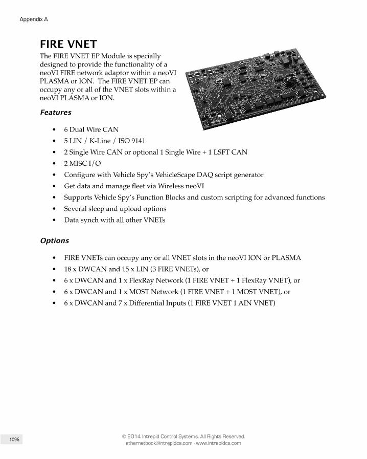
1096
Appendix A
© 2014 Intrepid Control Systems. All Rights Reserved. [email protected] • www.intrepidcs.com
FIRE VNETThe FIRE VNET EP Module is specially designed to provide the functionality of a neoVI FIRE network adaptor within a neoVI PLASMA or ION. The FIRE VNET EP can occupy any or all of the VNET slots within a neoVI PLASMA or ION.
Features
• 6 Dual Wire CAN• 5 LIN / K-Line / ISO 9141• 2 Single Wire CAN or optional 1 Single Wire + 1 LSFT CAN• 2 MISC I/O• Configure with Vehicle Spy’s VehicleScape DAQ script generator• Get data and manage fleet via Wireless neoVI• Supports Vehicle Spy’s Function Blocks and custom scripting for advanced functions• Several sleep and upload options• Data synch with all other VNETs
Options
• FIRE VNETs can occupy any or all VNET slots in the neoVI ION or PLASMA• 18 x DWCAN and 15 x LIN (3 FIRE VNETs), or• 6 x DWCAN and 1 x FlexRay Network (1 FIRE VNET + 1 FlexRay VNET), or• 6 x DWCAN and 1 x MOST Network (1 FIRE VNET + 1 MOST VNET), or• 6 x DWCAN and 7 x Differential Inputs (1 FIRE VNET 1 AIN VNET)
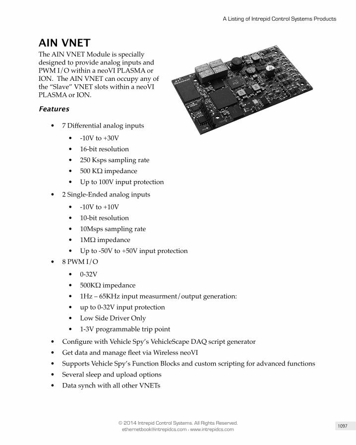
1097
A Listing of Intrepid Control Systems Products
© 2014 Intrepid Control Systems. All Rights Reserved. [email protected] • www.intrepidcs.com
AIN VNETThe AIN VNET Module is specially designed to provide analog inputs and PWM I/O within a neoVI PLASMA or ION. The AIN VNET can occupy any of the “Slave” VNET slots within a neoVI PLASMA or ION.
Features
• 7 Differential analog inputs
• -10V to +30V• 16-bit resolution• 250 Ksps sampling rate• 500 KΏ impedance• Up to 100V input protection
• 2 Single-Ended analog inputs
• -10V to +10V• 10-bit resolution• 10Msps sampling rate• 1MΏ impedance• Up to -50V to +50V input protection
• 8 PWM I/O
• 0-32V• 500KΏ impedance• 1Hz – 65KHz input measurment/output generation: • up to 0-32V input protection• Low Side Driver Only• 1-3V programmable trip point
• Configure with Vehicle Spy’s VehicleScape DAQ script generator• Get data and manage fleet via Wireless neoVI• Supports Vehicle Spy’s Function Blocks and custom scripting for advanced functions• Several sleep and upload options• Data synch with all other VNETs
1098
Appendix A
© 2014 Intrepid Control Systems. All Rights Reserved. [email protected] • www.intrepidcs.com
Options
• AIN VNETs can occupy any “slave” VNET slots in the neoVI ION or PLASMA• FIRE VNET must occupy the “master” VNET slot• 7 x Diff Inputs, 2 SE Inputs, 8 x PWM I/O, and 6 x DWCAN (AIN VNET + FIRE
VNET), or• 7 x Diff Inputs, 2 SE Inputs, 8 x PWM I/O, 1 x MOST Network , 6 x DWCAN
(AIN VNET + MOST VNET + FIRE VNET), or• 7 x Diff Inputs, 2 SE Inputs, 8 x PWM I/O, 1 x FlexRay Network , 6 x DWCAN
(AIN VNET + FlexRay VNET + FIRE VNET)
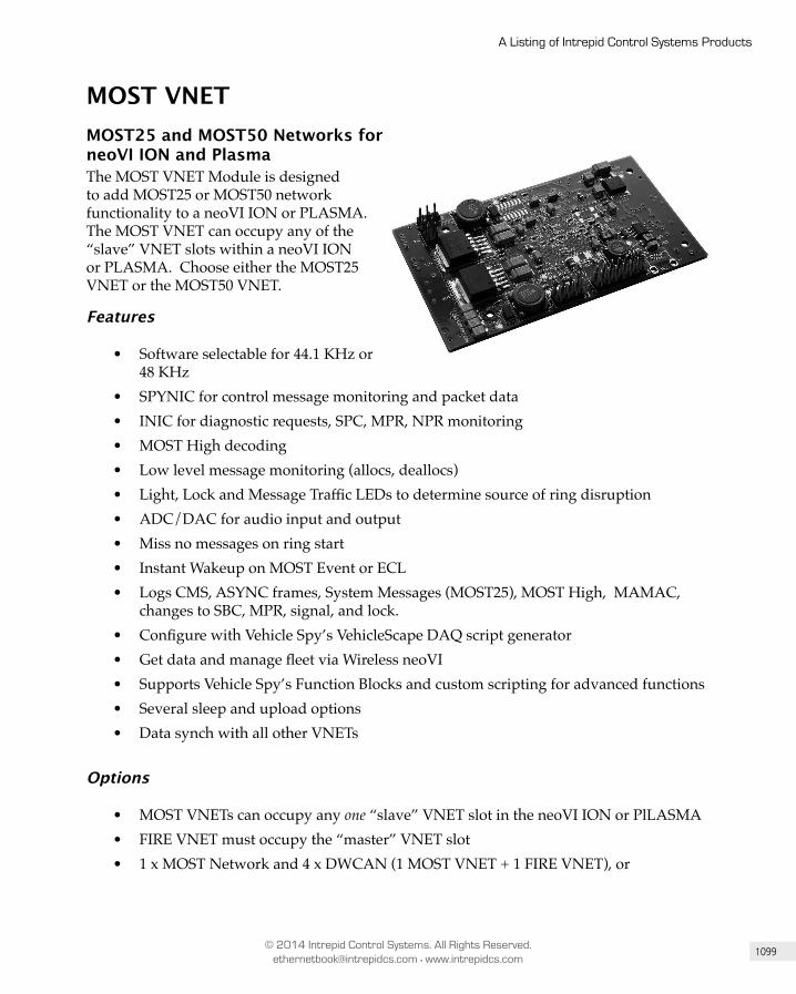
1099
A Listing of Intrepid Control Systems Products
© 2014 Intrepid Control Systems. All Rights Reserved. [email protected] • www.intrepidcs.com
MOST VNETMOST25 and MOST50 Networks for neoVI ION and PlasmaThe MOST VNET Module is designed to add MOST25 or MOST50 network functionality to a neoVI ION or PLASMA. The MOST VNET can occupy any of the “slave” VNET slots within a neoVI ION or PLASMA. Choose either the MOST25 VNET or the MOST50 VNET.
Features
• Software selectable for 44.1 KHz or 48 KHz
• SPYNIC for control message monitoring and packet data• INIC for diagnostic requests, SPC, MPR, NPR monitoring• MOST High decoding• Low level message monitoring (allocs, deallocs)• Light, Lock and Message Traffic LEDs to determine source of ring disruption• ADC/DAC for audio input and output• Miss no messages on ring start• Instant Wakeup on MOST Event or ECL• Logs CMS, ASYNC frames, System Messages (MOST25), MOST High, MAMAC,
changes to SBC, MPR, signal, and lock.• Configure with Vehicle Spy’s VehicleScape DAQ script generator• Get data and manage fleet via Wireless neoVI• Supports Vehicle Spy’s Function Blocks and custom scripting for advanced functions• Several sleep and upload options• Data synch with all other VNETs
Options
• MOST VNETs can occupy any one “slave” VNET slot in the neoVI ION or PlLASMA• FIRE VNET must occupy the “master” VNET slot• 1 x MOST Network and 4 x DWCAN (1 MOST VNET + 1 FIRE VNET), or
1100
Appendix A
© 2014 Intrepid Control Systems. All Rights Reserved. [email protected] • www.intrepidcs.com
• 1 x MOST Network , 4 x DWCAN, and 1 x FlexRay Network (1 MOST VNET + 1 FIRE VNET + 1 FlexRay VNET), or
• 1 x MOST Network , 4 x DWCAN, and 7 x Differential Inputs (1 MOST VNET + 1 FIRE VNET + 1 AIN VNET)
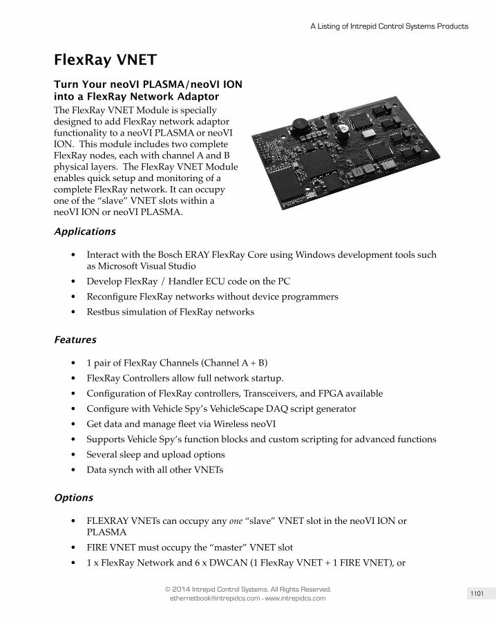
1101
A Listing of Intrepid Control Systems Products
© 2014 Intrepid Control Systems. All Rights Reserved. [email protected] • www.intrepidcs.com
FlexRay VNETTurn Your neoVI PLASMA/neoVI ION into a FlexRay Network AdaptorThe FlexRay VNET Module is specially designed to add FlexRay network adaptor functionality to a neoVI PLASMA or neoVI ION. This module includes two complete FlexRay nodes, each with channel A and B physical layers. The FlexRay VNET Module enables quick setup and monitoring of a complete FlexRay network. It can occupy one of the “slave” VNET slots within a neoVI ION or neoVI PLASMA.
Applications
• Interact with the Bosch ERAY FlexRay Core using Windows development tools such as Microsoft Visual Studio
• Develop FlexRay / Handler ECU code on the PC• Reconfigure FlexRay networks without device programmers• Restbus simulation of FlexRay networks
Features
• 1 pair of FlexRay Channels (Channel A + B)• FlexRay Controllers allow full network startup.• Configuration of FlexRay controllers, Transceivers, and FPGA available• Configure with Vehicle Spy’s VehicleScape DAQ script generator• Get data and manage fleet via Wireless neoVI• Supports Vehicle Spy’s function blocks and custom scripting for advanced functions• Several sleep and upload options• Data synch with all other VNETs
Options
• FLEXRAY VNETs can occupy any one “slave” VNET slot in the neoVI ION or PLASMA
• FIRE VNET must occupy the “master” VNET slot• 1 x FlexRay Network and 6 x DWCAN (1 FlexRay VNET + 1 FIRE VNET), or
1102
Appendix A
© 2014 Intrepid Control Systems. All Rights Reserved. [email protected] • www.intrepidcs.com
• 1 x FlexRay, 1 x MOST Network, and 6 x DWCAN (1 FlexRay VNET + 1 MOST VNET + 1 FIRE VNET), or
• 1 x FlexRay, 7 x Differential Inputs, and 6 x DWCAN (1 FlexRay VNET + 1 AIN VNET + 1 FIRE VNET)
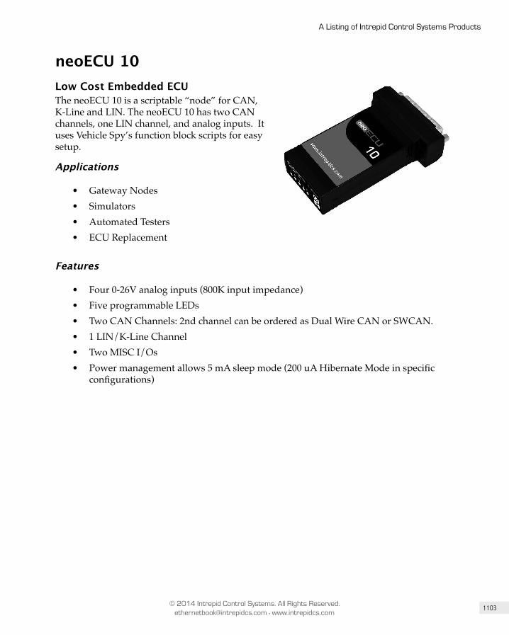
1103
A Listing of Intrepid Control Systems Products
© 2014 Intrepid Control Systems. All Rights Reserved. [email protected] • www.intrepidcs.com
neoECU 10Low Cost Embedded ECUThe neoECU 10 is a scriptable “node” for CAN, K-Line and LIN. The neoECU 10 has two CAN channels, one LIN channel, and analog inputs. It uses Vehicle Spy’s function block scripts for easy setup.
Applications
• Gateway Nodes• Simulators• Automated Testers• ECU Replacement
Features
• Four 0-26V analog inputs (800K input impedance)• Five programmable LEDs• Two CAN Channels: 2nd channel can be ordered as Dual Wire CAN or SWCAN.• 1 LIN/K-Line Channel• Two MISC I/Os• Power management allows 5 mA sleep mode (200 uA Hibernate Mode in specific
configurations)
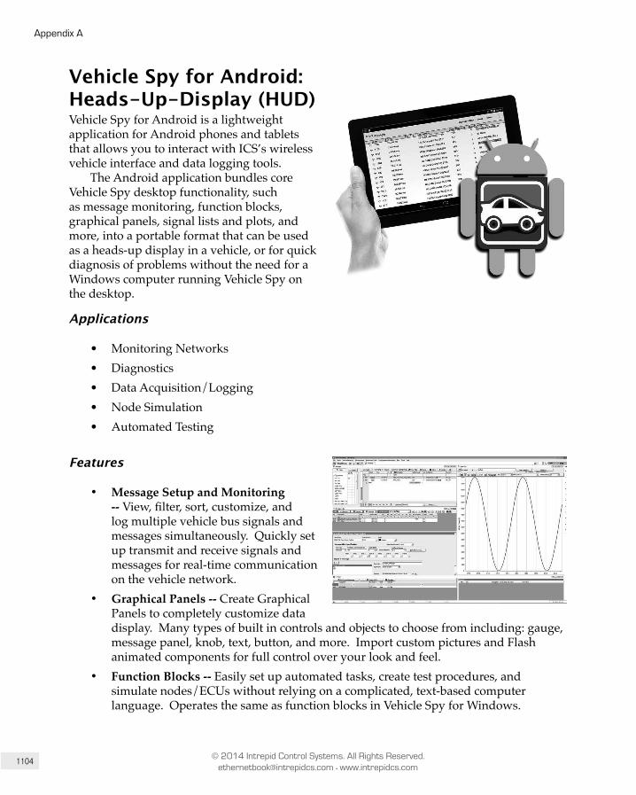
1104
Appendix A
© 2014 Intrepid Control Systems. All Rights Reserved. [email protected] • www.intrepidcs.com
Vehicle Spy for Android: Heads-Up-Display (HUD)Vehicle Spy for Android is a lightweight application for Android phones and tablets that allows you to interact with ICS’s wireless vehicle interface and data logging tools.
The Android application bundles core Vehicle Spy desktop functionality, such as message monitoring, function blocks, graphical panels, signal lists and plots, and more, into a portable format that can be used as a heads-up display in a vehicle, or for quick diagnosis of problems without the need for a Windows computer running Vehicle Spy on the desktop.
Applications
• Monitoring Networks• Diagnostics• Data Acquisition/Logging• Node Simulation• Automated Testing
Features
• Message Setup and Monitoring -- View, filter, sort, customize, and log multiple vehicle bus signals and messages simultaneously. Quickly set up transmit and receive signals and messages for real-time communication on the vehicle network.
• Graphical Panels -- Create Graphical Panels to completely customize data display. Many types of built in controls and objects to choose from including: gauge, message panel, knob, text, button, and more. Import custom pictures and Flash animated components for full control over your look and feel.
• Function Blocks -- Easily set up automated tasks, create test procedures, and simulate nodes/ECUs without relying on a complicated, text-based computer language. Operates the same as function blocks in Vehicle Spy for Windows.

1105
A Listing of Intrepid Control Systems Products
© 2014 Intrepid Control Systems. All Rights Reserved. [email protected] • www.intrepidcs.com
• Signal Plots and Signal Lists -- Live plot many signals against time or as an X-Y Plot. Stack or superimpose signals. Display live value of signals in digital displays.
Figure A-6: Vehicle Spy for Android has large buttons and a simple dashboard that helps you find the information you’re after in a snap.
Figure A-7: Track ECU activity on the move with Vehicle Spy for Android.