Embed Size (px)
Citation preview
1
Automotive EMC
IEEE EMC Society
Eastern North Carolina Section
February 9, 2010
By
Mark Steffka
IEEE EMCS Distinguished Lecturer
Email: [email protected]
IEEE
2
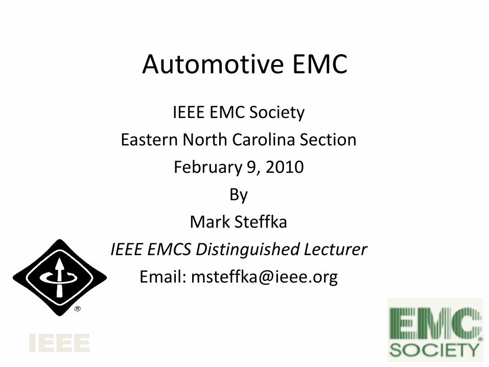
Automotive Systems “Past and Present”
• Today’s vehicles contain three centuries of technology…19th century internal combustion engines…combined with 20th century electrical systems…and 21st century electronics….
Automotive EMC...from Spark to
Satellite…
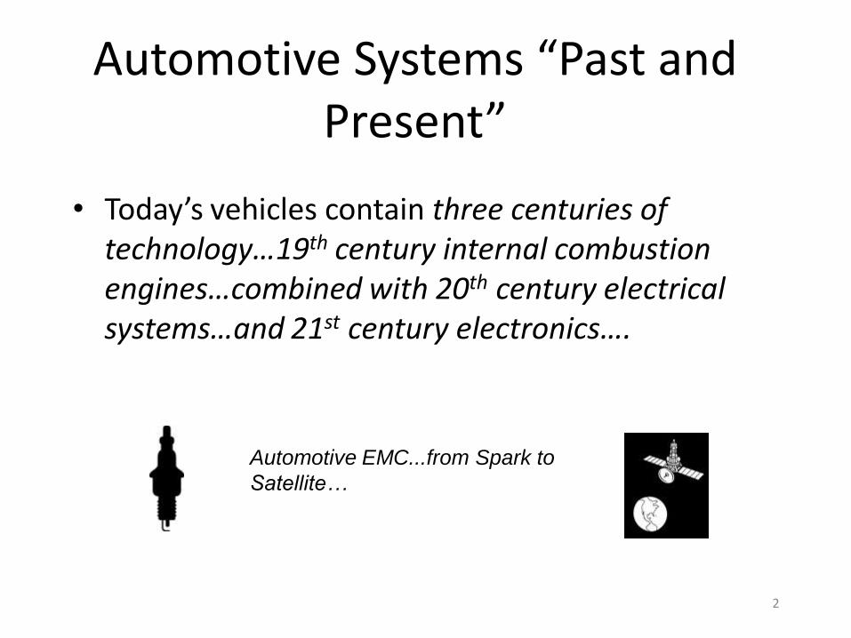
Automotive EMC Goals
• Highest priority is to exceed expectations of the customer.
• Meet challenges of technology content in vehicles.
• Develop organization that supports EMC.
Marketplace Demands
OrganizationalTechnical
3
Automotive EMC Case Studies
• Emissions: Microprocessor clock harmonic was on two way radio frequency – rendering radio communication impossible.
• Immunity (the Automotive characterization of susceptibility): An engine and transmission seemed defective due to control system malfunctions – cause was a change from a metal to a non-conductive component package.
4
5
Vehicle Generated Radiated “Noise”
•Vehicle systems can be responsible for onboard noise generation as a by-product of vehicle operation.
•In the automotive industry, this noise has been classified into two categories:
– Broadband (typically due to electrical arcing)
» Typically referred to as “Arc and Spark”
– Narrowband (typically due to active electronics)
» Typically used to refer to all items NOT “Arc and Spark”
6
Representation Of Noise Bandwidth
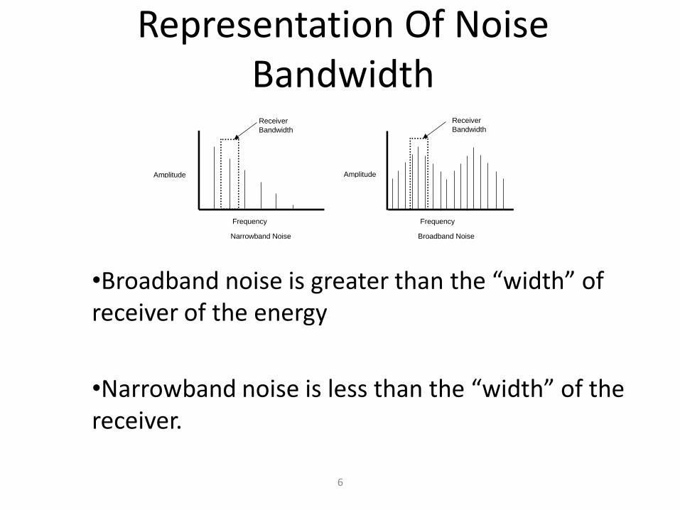
•Broadband noise is greater than the “width” of receiver of the energy
•Narrowband noise is less than the “width” of the receiver.
Frequency Frequency
Amplitude Amplitude
Receiver
Bandwidth
Receiver
Bandwidth
Narrowband Noise Broadband Noise
7
Typical Sources Of Broadband Noise
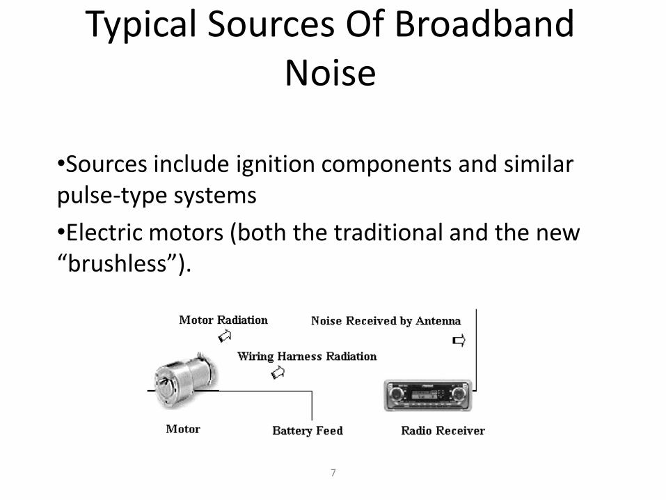
•Sources include ignition components and similar pulse-type systems
•Electric motors (both the traditional and the new “brushless”).
Consequences Of Broadband Noise Sources
• BAD –Due to functions that are required for basic vehicle operation (such as ignition or inductive devices).
• BAD – Can have both conducted AND radiated coupling path.
• GOOD – Energy spread out – may have minimal effect on potential receivers (intentional and unintentional).
8
9
Microprocessors And Narrowband Noise
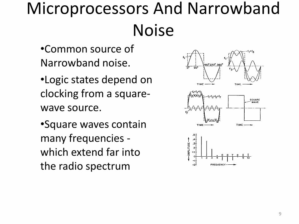
•Common source of Narrowband noise.
•Logic states depend on clocking from a square-wave source.
•Square waves contain many frequencies -which extend far into the radio spectrum
Consequences Of Narrowband Noise Sources
• BAD -May be many sources on a vehicle due to proliferation of active devices.
• BAD - Receivers can appear to function “almost normal”.
• GOOD - Can be addressed in component design process.
10
11
Immunity: Auto Industry Practices
• The Automotive industry ensures product immunityby first planning to “design in” appropriate immunity characteristics to meet both “Off Board” and “On Board” source of electromagnetic energy.
• System and component testing can be conducted by simulating “external” sources either by radiation or conduction (such as “bulk current injection”) to ensure immunity characteristics.
12
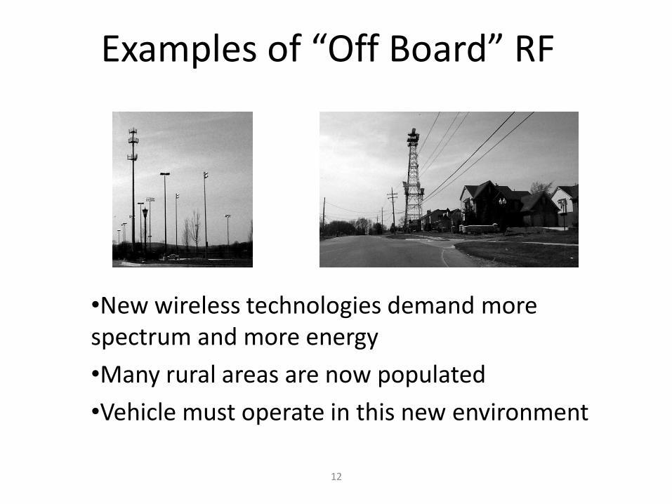
Examples of “Off Board” RF
•New wireless technologies demand more spectrum and more energy
•Many rural areas are now populated
•Vehicle must operate in this new environment
13
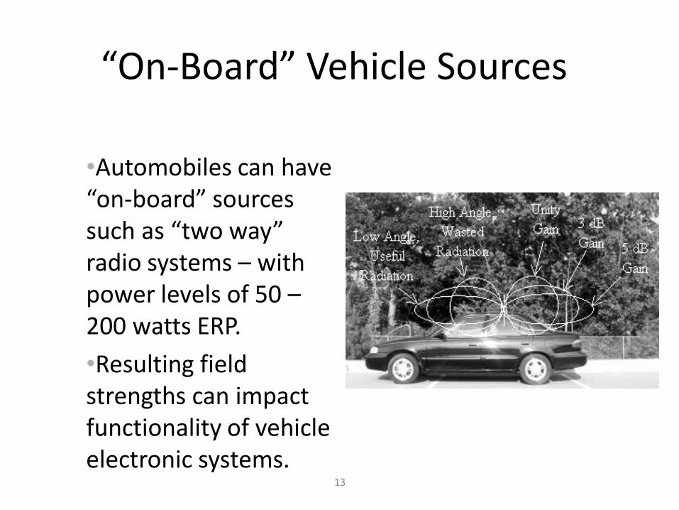
“On-Board” Vehicle Sources
•Automobiles can have “on-board” sources such as “two way” radio systems – with power levels of 50 –200 watts ERP.
•Resulting field strengths can impact functionality of vehicle electronic systems.
14
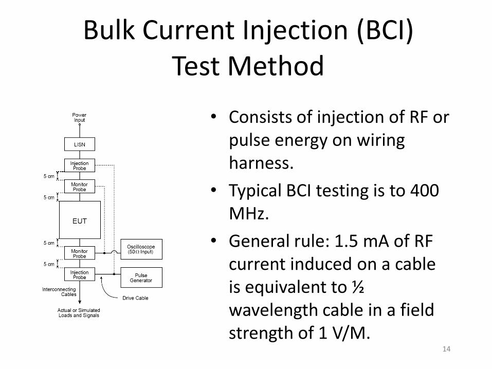
Bulk Current Injection (BCI) Test Method
• Consists of injection of RF or pulse energy on wiring harness.
• Typical BCI testing is to 400 MHz.
• General rule: 1.5 mA of RF current induced on a cable is equivalent to ½ wavelength cable in a field strength of 1 V/M.
15
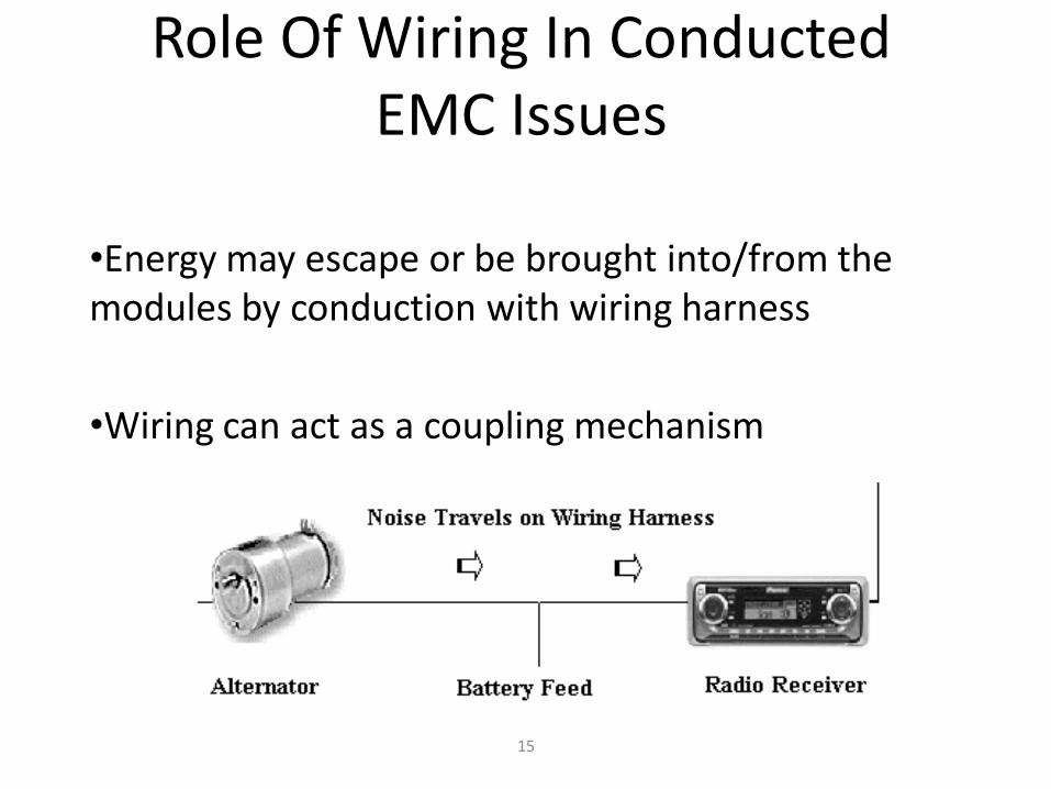
Role Of Wiring In Conducted EMC Issues
•Energy may escape or be brought into/from the modules by conduction with wiring harness
•Wiring can act as a coupling mechanism
16
Why Wiring is Important to Automotive EMC
• Early systems (and vehicles) had few components to be connected - recent systems have increased wiring complexity, similar to many non-automotive systems.
• Many automotive engineers consider wiring “just a piece of wire” and the chassis is “GROUND” (this is not true – impedance exists).
• Wiring will still be used for many systems in the future and we need to understand relevant physical parameters.
17
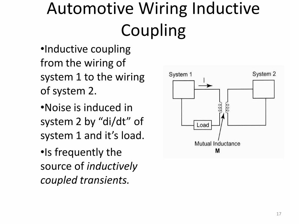
Automotive Wiring Inductive Coupling
•Inductive coupling from the wiring of system 1 to the wiring of system 2.
•Noise is induced in system 2 by “di/dt” of system 1 and it’s load.
•Is frequently the source of inductively coupled transients.
18
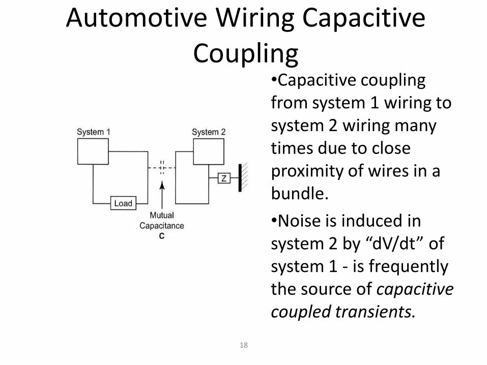
Automotive Wiring Capacitive Coupling
•Capacitive coupling from system 1 wiring to system 2 wiring many times due to close proximity of wires in a bundle.
•Noise is induced in system 2 by “dV/dt” of system 1 - is frequently the source of capacitive coupled transients.
19
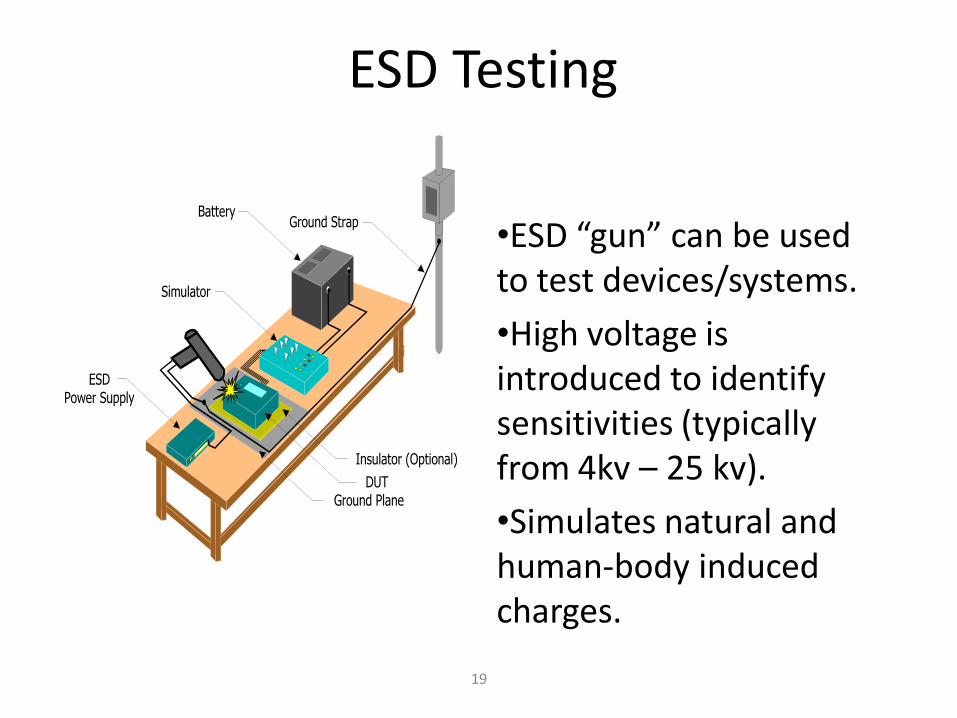
ESD Testing
ESDPower Supply
Simulator
Battery
Insulator (Optional)
Ground Plane
Ground Strap
DUT
•ESD “gun” can be used to test devices/systems.
•High voltage is introduced to identify sensitivities (typically from 4kv – 25 kv).
•Simulates natural and human-body induced charges.
Automotive EMC Is Changing
• Global shift towards new propulsion systems is changing the content of vehicles.
• These new systems will need appropriate EMC methods, standards, and utilization of EMC approaches from other specialties.
• Many of these systems will utilize high voltage components and have safety aspects that may make automotive EMC more difficult and safety takes priority!
20
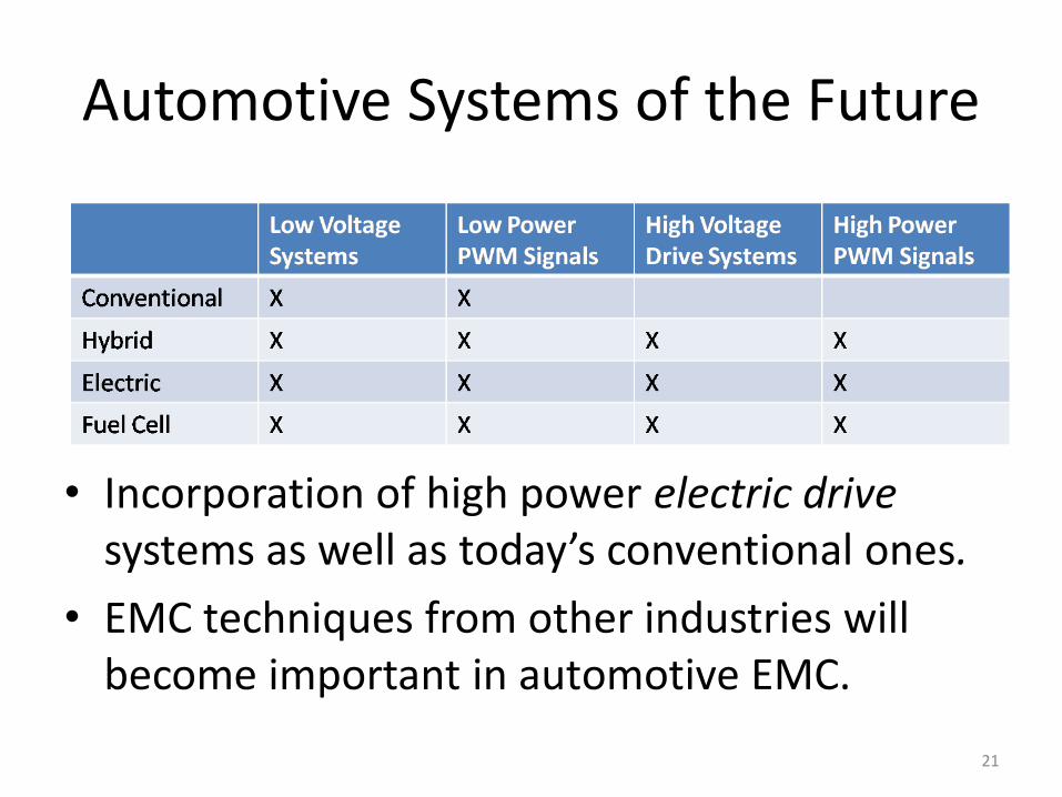
Automotive Systems of the Future
• Incorporation of high power electric drive systems as well as today’s conventional ones.
• EMC techniques from other industries will become important in automotive EMC.
21
Why Use Electric Drives?
• Advances in power electronics as well as motor design and manufacturing have made electric drives very attractive.
• The benefits of electric drives include high efficiency with lower mass as a result of implementation of adjustable/variable speed or frequency drives (ASD/VSD/VFD).
• Provide energy efficiency and flexibility over existing “conventional” drive systems.
22
Electric Drive Control Systems
• Control systems for electric drives typically consist of active switching of the primary current for the motor (similar to basic switching power supply).
• Output voltage is determined by switching speed and “on” duration of the drive transistor's).
• Multiple phases can be obtained by utilizing multiple driver transistors with appropriate timing.
23
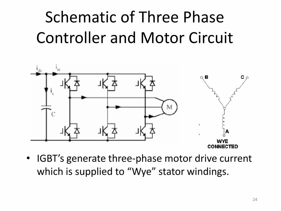
Schematic of Three Phase Controller and Motor Circuit
• IGBT’s generate three-phase motor drive current which is supplied to “Wye” stator windings.
24
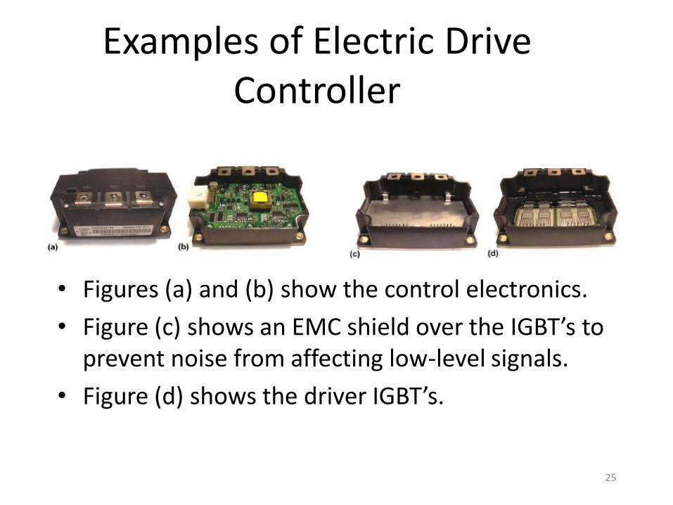
Examples of Electric Drive Controller
• Figures (a) and (b) show the control electronics.
• Figure (c) shows an EMC shield over the IGBT’s to prevent noise from affecting low-level signals.
• Figure (d) shows the driver IGBT’s.
25
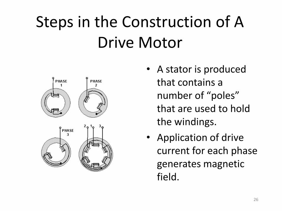
Steps in the Construction of A Drive Motor
• A stator is produced that contains a number of “poles” that are used to hold the windings.
• Application of drive current for each phase generates magnetic field.
26
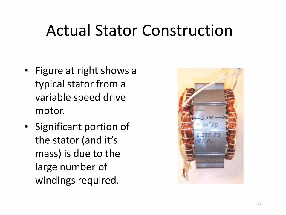
Actual Stator Construction
• Figure at right shows a typical stator from a variable speed drive motor.
• Significant portion of the stator (and it’s mass) is due to the large number of windings required.
27
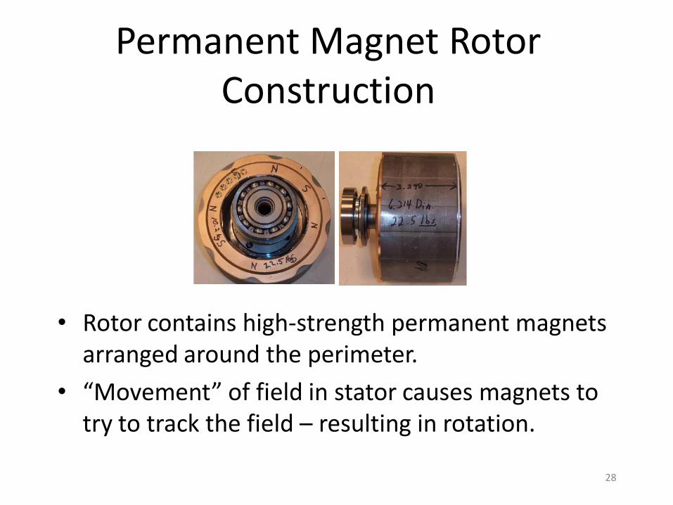
Permanent Magnet Rotor Construction
• Rotor contains high-strength permanent magnets arranged around the perimeter.
• “Movement” of field in stator causes magnets to try to track the field – resulting in rotation.
28
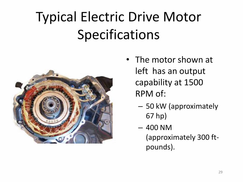
Typical Electric Drive Motor Specifications
• The motor shown at left has an output capability at 1500 RPM of:
– 50 kW (approximately 67 hp)
– 400 NM (approximately 300 ft-pounds).
29
Balancing EMC and Performance Requirements
• Important to understand the speed of operation of electro-mechanical devices compared to fast “slew rate” power signals from power drive devices such as Insulated Gate Bipolar Transistors (IGBT).
• The switching operation results in low power dissipation (in the drive devices) along with:
– Semiconductor operation at an order of magnitude faster than the response time of electromechanical devices.
– Causing radiated/conducted emission issues.
30
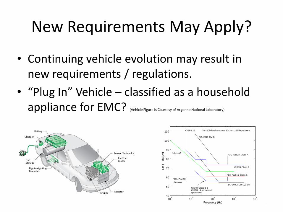
New Requirements May Apply?
• Continuing vehicle evolution may result in new requirements / regulations.
• “Plug In” Vehicle – classified as a household appliance for EMC? (Vehicle Figure Is Courtesy of Argonne National Laboratory)
3110
4
105
106
107
108
40
50
60
70
80
90
100
110
Frequency (Hz)
Lim
it -
- d
B(µ
V) CE102
CISPR 15
CISPR Class A
FCC Part 15: Class A
FCC, Part 18
Ultrasonic
FCC Part 15: Class B
CISPR Class B &CISPR 14 householdappliances
DO-160D: Cat B
DO-160D: Cat L ,M&H
DO-160D level assumes 50-ohm LISN impedance
Summary
• Automotive EMC has been continually evolving to meet the challenges that new technology brings.
• The automotive industry in undergoing a complete “re-invention” of itself to meet demands of today’s world.
• Understanding of the basics of these new technologies and will enable Automotive EMC to meet these challenges!
32