Embed Size (px)
Citation preview
Altera Corporation AN-407-1.0
Version 1.0, April 2006
Automotive Audio ReferenceDesign
Application Note 407
Introduction The Altera® Automotive Audio Reference Design demonstrates Altera Cyclone™ FPGAs in an audio processing role targeted at the automotive sector. The reference design runs on a Nios® development board, Cyclone® edition, or Cyclone II edition, with an eight-channel Santa Cruz audio digital-to analogue converter (DAC) board.
f For information on the Nios development board, Cyclone edition, refer to the Nios Development Board Reference Manual, Cyclone Edition; For information on the Nios development board, Cyclone II edition, refer to the Nios Development Board Reference Manual, Cyclone II Edition; for information on the Santa Cruz Audio DAC board, contact your Altera representative.
The reference design has the following features:
■ Audio input samples stored as .wav files on a compact flash (CF) card
■ Seven-band graphic equalizer■ Centre mono, sub mono, front stereo and rear stereo audio outputs
(six channels)■ Delay line (up to 10 ms) for front or rear delay compensation■ Up to six-band parametric equalizers for each of six output channels■ Supports standard digital audio sample rates, for example 44.1 and
48 kHz
Functional Description
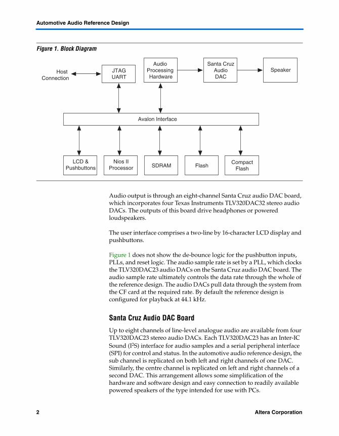
Figure 1 shows the Automotive Audio Reference Design block diagram. Audio input sound samples are stored in .wav files in a CF card using a FAT32 filing system. A 512 MB CF card can hold approximately 30 minutes of uncompressed 24-bit stereo audio sampled at 48 kHz.
1Preliminary
Automotive Audio Reference Design
Figure 1. Block Diagram
Audio output is through an eight-channel Santa Cruz audio DAC board, which incorporates four Texas Instruments TLV320DAC32 stereo audio DACs. The outputs of this board drive headphones or powered loudspeakers.
The user interface comprises a two-line by 16-character LCD display and pushbuttons.
Figure 1 does not show the de-bounce logic for the pushbutton inputs, PLLs, and reset logic. The audio sample rate is set by a PLL, which clocks the TLV320DAC23 audio DACs on the Santa Cruz audio DAC board. The audio sample rate ultimately controls the data rate through the whole of the reference design. The audio DACs pull data through the system from the CF card at the required rate. By default the reference design is configured for playback at 44.1 kHz.
Santa Cruz Audio DAC Board
Up to eight channels of line-level analogue audio are available from four TLV320DAC23 stereo audio DACs. Each TLV320DAC23 has an Inter-IC Sound (I2S) interface for audio samples and a serial peripheral interface (SPI) for control and status. In the automotive audio reference design, the sub channel is replicated on both left and right channels of one DAC. Similarly, the centre channel is replicated on left and right channels of a second DAC. This arrangement allows some simplification of the hardware and software design and easy connection to readily available powered speakers of the type intended for use with PCs.
Audio Processing Hardware
Santa CruzAudioDAC
Speaker
Avalon Interface
JTAGUART
Host Connection
LCD &Pushbuttons
Nios IIProcessor SDRAM Flash
CompactFlash
2 Altera CorporationPreliminary
Functional Description
No further processing of the line-level outputs is required because the anti-alias filter is internal to the TLV320DAC23. The outputs are AC coupled using a series capacitor. A series termination resistor limits the current if the outputs are accidentally short circuited.
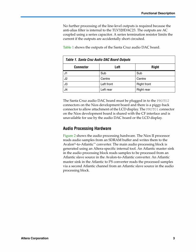
Table 1 shows the outputs of the Santa Cruz audio DAC board.
The Santa Cruz audio DAC board must be plugged in to the PROTO2 connectors on the Nios development board and there is a piggy-back connector to allow attachment of the LCD display. The PROTO1 connector on the Nios development board is shared with the CF interface and is unavailable for use by the audio DAC board or the LCD display.
Audio Processing Hardware
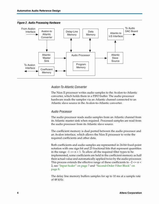
Figure 2 shows the audio processing hardware. The Nios II processor reads audio samples from an SDRAM buffer and writes them to the Avalon®-to-Atlantic™ converter. The main audio processing block is generated using an Altera-specific internal tool. An Atlantic master sink in the audio processing block reads samples to be processed from an Atlantic slave source in the Avalon-to-Atlantic converter. An Atlantic master sink in the Atlantic to I2S converter reads the processed samples via a second Atlantic channel from an Atlantic slave source in the audio processing block.
Table 1. Santa Cruz Audio DAC Board Outputs
Connector Left Right
J1 Sub Sub
J2 Centre Centre
J3 Left front Right front
J4 Left rear Right rear
Altera Corporation 3Preliminary
Automotive Audio Reference Design
Figure 2. Audio Processing Hardware
Avalon-To-Atlantic Converter
The Nios II processor writes audio samples to the Avalon-to-Atlantic converter, which holds them in a FIFO buffer. The audio processor hardware reads the samples via an Atlantic channel connected to an Atlantic slave source in the Avalon-to-Atlantic converter.
Audio Processor
The audio processor reads audio samples from an Atlantic channel from its Atlantic master sink when required. Processed samples are read from the audio processor from its Atlantic slave source.
The coefficient memory is dual ported between the audio processor and an Avalon interface, which allows the Nios II processor to write the required coefficients and other data.
Both coefficients and audio samples are represented in 24-bit fixed-point notation with one sign bit and 23 fractional bits that represent quantities in the range –1 <= n < 1. To allow all the required filter types to be implemented, some coefficients are held in the coefficient memory as half their actual value and automatically applied twice by the audio processor. This process extends the effective range of these coefficients to –2 <= n < 2, see “Input Scaler” on page 7 and “Second-Order Filter Block” on page 8.
The delay line memory buffers samples for up to 10 ms at a sample rate of 48 kHz.
Atlantic MasterSink
Avalon-toAtlanitc
Converter
From AvalonInterface
To AvalonInterface
To Audio DAC Board
AtlanticSlave Source
Atlantic-toI2S Interface
Delay-LineMemory
DataMemory
CoefficientMemory
ProgramMemory
Audio Processor
4 Altera CorporationPreliminary
Functional Description
The data memory has one read and one write port and holds intermediate values during calculation and the state of each second-order infinite impulse response (IIR) filter.
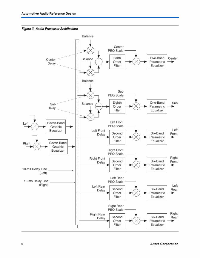
Figure 3 shows the audio processor architecture. For convenience, the output samples from the sub and centre channels are duplicated so that eight output samples are generated for each pair (left and right) of input samples.
Altera Corporation 5Preliminary
Automotive Audio Reference Design
Figure 3. Audio Processor Architecture
LeftFrontSix-Band
ParametricEqualizer
SecondOrderFilter
Balance
Balance
Left FrontPEQ Scale
Left FrontDelay
Right
10-ms Delay Line(Left)
CenterDelay
RightFrontSix-Band
ParametricEqualizer
SecondOrderFilter
Right FrontPEQ Scale
Right FrontDelay
LeftRearSix-Band
ParametricEqualizer
SecondOrderFilter
Left RearPEQ Scale
Left RearDelay
RightRearSix-Band
ParametricEqualizer
SecondOrderFilter
Right RearPEQ Scale
Right RearDelay
CenterFive-BandParametricEqualizer
ForthOrderFilter
CenterPEQ Scale
Seven-BandGraphic
Equalizer
Left Seven-BandGraphic
Equalizer
10-ms Delay Line(Right)
Balance
BalanceSubDelay
SubOne-BandParametricEqualizer
EighthOrderFilter
SubPEQ Scale
6 Altera CorporationPreliminary
Functional Description
Input ScalerThe input scaler may be used as a volume control and also to attenuate samples to prevent overflow during subsequent processing of a filter response with greater than unity gain. The input scaler is specified as half its desired scale factor and automatically applied twice by the custom processor. This process extends the effective range of the scaler to –2 <= n < 2, which allows a unity scale factor to be implemented.
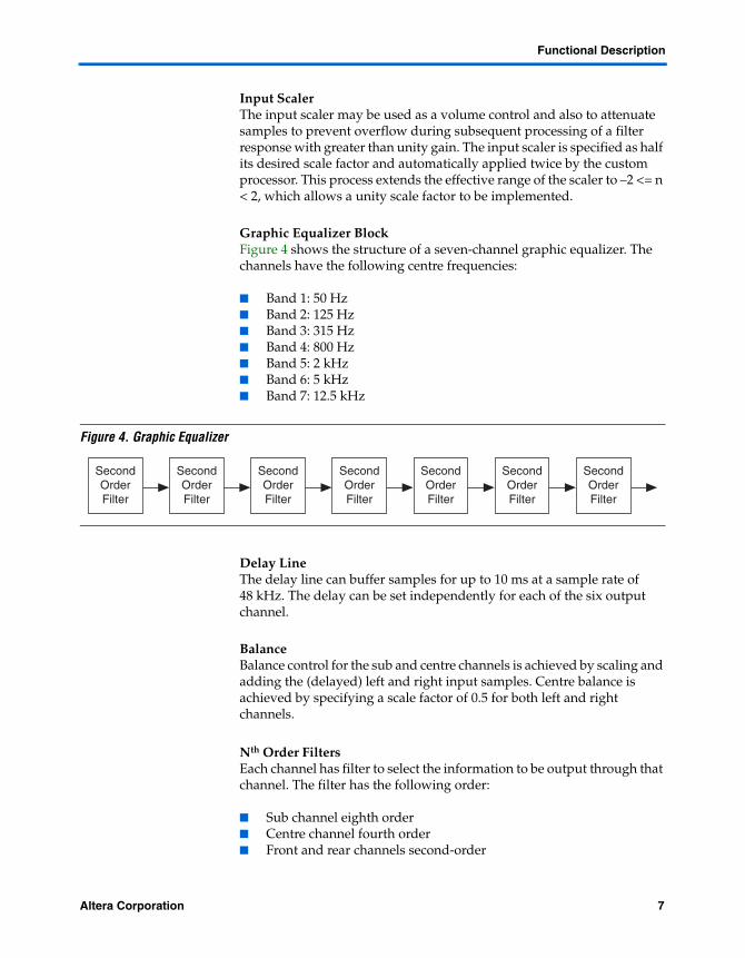
Graphic Equalizer BlockFigure 4 shows the structure of a seven-channel graphic equalizer. The channels have the following centre frequencies:
■ Band 1: 50 Hz■ Band 2: 125 Hz■ Band 3: 315 Hz■ Band 4: 800 Hz■ Band 5: 2 kHz■ Band 6: 5 kHz■ Band 7: 12.5 kHz
Figure 4. Graphic Equalizer
Delay LineThe delay line can buffer samples for up to 10 ms at a sample rate of 48 kHz. The delay can be set independently for each of the six output channel.
BalanceBalance control for the sub and centre channels is achieved by scaling and adding the (delayed) left and right input samples. Centre balance is achieved by specifying a scale factor of 0.5 for both left and right channels.
Nth Order FiltersEach channel has filter to select the information to be output through that channel. The filter has the following order:
■ Sub channel eighth order■ Centre channel fourth order■ Front and rear channels second-order
SecondOrderFilter
SecondOrderFilter
SecondOrderFilter
SecondOrderFilter
SecondOrderFilter
SecondOrderFilter
SecondOrderFilter
Altera Corporation 7Preliminary
Automotive Audio Reference Design
These filters are normally high-pass or low-pass response.
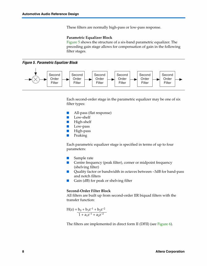
Parametric Equalizer BlockFigure 5 shows the structure of a six-band parametric equalizer. The preceding gain stage allows for compensation of gain in the following filter stages.
Figure 5. Parametric Equalizer Block
Each second-order stage in the parametric equalizer may be one of six filter types:
■ All-pass (flat response)■ Low-shelf■ High-shelf■ Low-pass■ High-pass■ Peaking
Each parametric equalizer stage is specified in terms of up to four parameters:
■ Sample rate■ Centre frequency (peak filter), corner or midpoint frequency
(shelving filter)■ Quality factor or bandwidth in octaves between –3dB for band-pass
and notch filters■ Gain (dB) for peak or shelving filter
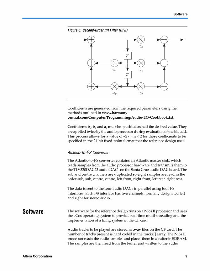
Second-Order Filter BlockAll filters are built up from second-order IIR biquad filters with the transfer function:
H(z) = b0 + b1z–1 + b2z–2
1 + a1z–1 + a2z–2
The filters are implemented in direct form II (DFII) (see Figure 6).
SecondOrderFilter
SecondOrderFilter
SecondOrderFilter
SecondOrderFilter
SecondOrderFilter
SecondOrderFilter
8 Altera CorporationPreliminary
Software
Figure 6. Second-Order IIR Filter (DFII)
Coefficients are generated from the required parameters using the methods outlined in www.harmony-central.com/Computer/Programming/Audio-EQ-Cookbook.txt.
Coefficients b0, b1 and a1 must be specified as half the desired value. They are applied twice by the audio processor during evaluation of the biquad. This process allows for a value of –2 <= n < 2 for those coefficients to be specified in the 24-bit fixed-point format that the reference design uses.
Atlantic-To-I2S Converter
The Atlantic-to-I2S converter contains an Atlantic master sink, which reads samples from the audio processor hardware and transmits them to the TLV320DAC23 audio DACs on the Santa Cruz audio DAC board. The sub and centre channels are duplicated so eight samples are read in the order sub, sub, centre, centre, left front, right front, left rear, right rear.
The data is sent to the four audio DACs in parallel using four I2S interfaces. Each I2S interface has two channels normally designated left and right for stereo audio.
Software The software for the reference design runs on a Nios II processor and uses the eCos operating system to provide real-time multi-threading and the implementation of a filing system in the CF card.
Audio tracks to be played are stored as .wav files on the CF card. The number of tracks present is hard coded in the tracks[] array. The Nios II processor reads the audio samples and places them in a buffer in SDRAM. The samples are then read from the buffer and written to the audio
b1
Z-1
Z-1
b0
b2
-a1
-a2
Altera Corporation 9Preliminary
Automotive Audio Reference Design
processing hardware as required. When one track finishes playing the Nios II processor closes the .wav file and opens the next one. Play wraps around from the end of the last track to the beginning of the first track.
A number of threads and interrupt handlers co-ordinate the operation of the reference design. User interaction is with the pushbuttons on the Nios development board and the two-line 16 character display included with the development board kit.
The reference design is a standalone system with no need to be connected to the Nios II integrated design environment (IDE). The software and FPGA programming file are programmed into the Nios development board with the flash programmer utility in the Nios II IDE.
Initialization
On reset the reference design software main() performs the following initial setup:
■ Opens the LCD display device■ Registers the interrupt handlers (see “Interrupts” on page 10)■ Creates and starts threads (see “Threads” on page 11)■ Checks that the CF file system can be accessed
If the DEBUG macro is defined, /dev/ttydiag is also opened to allow diagnostic information to be displayed. This process requires that the Nios development board, Cyclone edition, is connected to a Nios II terminal on a host PC.
Interrupts
Interrupts signal when you press a pushbutton or when the FIFO buffer within the Avalon-to-Atlantic converter has emptied to its threshold and requires more data.
PIO (Button) Interrupt
The button PIO interrupts on a rising edge on any of the pushbutton interrupts—when the pushbutton is released. The reference design hardware includes additional debounce circuitry between the pushbuttons and the PIO to prevent false triggering. The button PIO interrupt service routine (ISR) defers processing of the interrupt to the button_PIO_DSR() thread (deferred service routine (DSR)).
The button PIO DSR decodes the state of the pushbuttons on the Nios development board, Cyclone edition, based upon which menu is currently being displayed on the LCD. The appropriate actions are taken
10 Altera CorporationPreliminary
Software
and the menu state updated after which PIO interrupts are re-enabled and the thread terminates. The LCD display is updated with the new menu state next time the lcd_update() thread runs.
Avalon To Atlantic Converter Interrupt
The Avalon-to-Atlantic converter requests an interrupt when the fill level of its FIFO buffer is below the threshold (see Verilog HDL source code). Processing of this interrupt is deferred to the atlantic_DSR() thread.
The Atlantic DSR copies data from the audio sample buffer (managed by the read_wave() thread) to the Avalon-to-Atlantic converter's FIFO buffer.
Atlantic-To-I2S Converter Interrupt
The reference design does not currently use this interrupt.
Threads
Three threads flash the LEDs, update the LCD display, and read the .wav files from CF.
led_flash(cyg_addrword_t data)
The led_flash thread runs periodically to flash each of the LEDs on the Nios development board, Cyclone edition, as an indication the eCos threading mechanism is alive. The flash is set by the data parameter passed to thread and is twice as fast when playing an audio track.
lcd_update(cyg_addrword_t data)
The lcd_update thread is the lowest priority thread and runs periodically to update the LCD display dependant upon which menu should be displayed following input via the pushbuttons.
read_wave(cyg_addrword_t data)
The read_wave thread is the highest priority thread and runs almost continuously when no other activity is required. This thread monitors the space available in the audio sample buffer and reads data from the CF as required to keep the buffer full.
Altera Corporation 11Preliminary
Automotive Audio Reference Design
Graphic Equalizer
The graphic equalizer is initialized with a flat response and may be changed with the user interface (see “User Interface” on page 12).
Delay Line
The delay line is initialized with no delay on any of the channels.
Balance
The balance control for the sub and centre channels is set to the centre position (equal contribution from left and right input channels).
Nth Order Filters
In the reference design the nth order filters are preset with the following responses:
■ Sub channel: low-pass, second-order corner frequency 200 Hz■ Centre channel: high-pass, second-order corner frequency 200 Hz
plus low-pass second-order corner frequency 1,200 Hz■ Front channel: high-pass, second-order, corner frequency 200 Hz■ Rear channel: flat response
To change the response of the parametric equalizers, modify the cusp_init() function in the cusp_auto_audio.c source file.
Parametric Equalizers
The parametric equalizers in the reference design are all preset with flat responses
To change the response of the parametric equalizers, modify the cusp_init() function in the cusp_auto_audio.c source file.
User Interface
The user interface allows audio tracks in .wav format to be played from the CF card. It also allows the graphic equalizer and volume settings to be changed.
Figure 7 shows the initial menu displayed on the LCD controller.
12 Altera CorporationPreliminary
Software
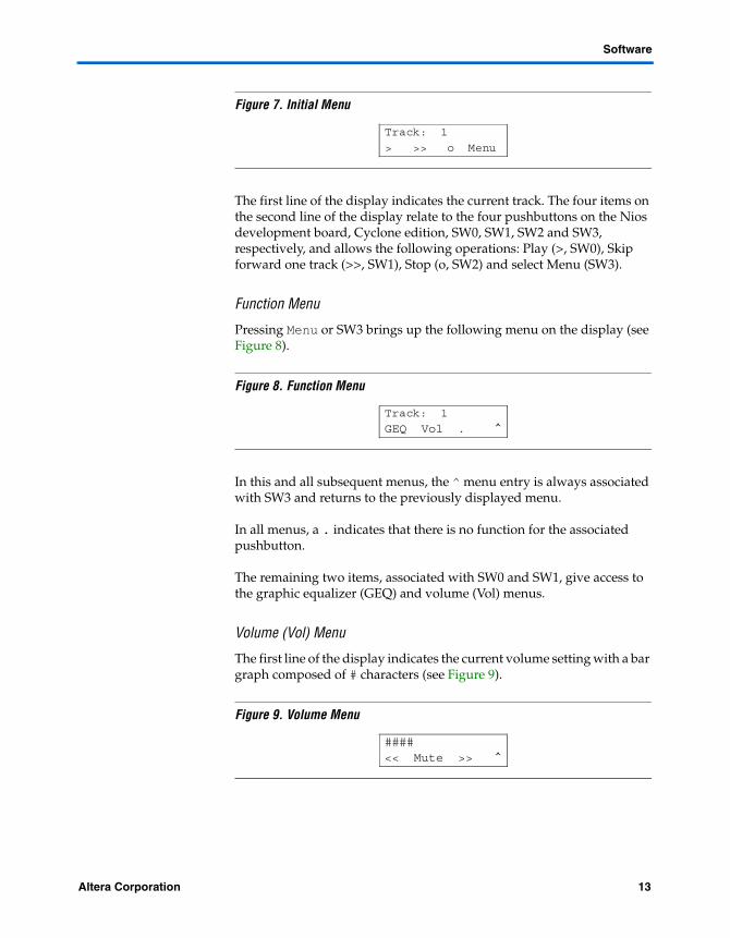
Figure 7. Initial Menu
The first line of the display indicates the current track. The four items on the second line of the display relate to the four pushbuttons on the Nios development board, Cyclone edition, SW0, SW1, SW2 and SW3, respectively, and allows the following operations: Play (>, SW0), Skip forward one track (>>, SW1), Stop (o, SW2) and select Menu (SW3).
Function Menu
Pressing Menu or SW3 brings up the following menu on the display (see Figure 8).
Figure 8. Function Menu
In this and all subsequent menus, the ^ menu entry is always associated with SW3 and returns to the previously displayed menu.
In all menus, a . indicates that there is no function for the associated pushbutton.
The remaining two items, associated with SW0 and SW1, give access to the graphic equalizer (GEQ) and volume (Vol) menus.
Volume (Vol) Menu
The first line of the display indicates the current volume setting with a bar graph composed of # characters (see Figure 9).
Figure 9. Volume Menu
Track: 1
> >> o Menu
Track: 1
GEQ Vol . ^
####
<< Mute >> ^
Altera Corporation 13Preliminary
Automotive Audio Reference Design
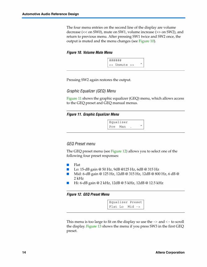
The four menu entries on the second line of the display are volume decrease (<< on SW0), mute on SW1, volume increase (>> on SW2), and return to previous menu. After pressing SW1 twice and SW2 once, the output is muted and the menu changes (see Figure 10).
Figure 10. Volume Mute Menu
Pressing SW2 again restores the output.
Graphic Equalizer (GEQ) Menu
Figure 11 shows the graphic equalizer (GEQ) menu, which allows access to the GEQ preset and GEQ manual menus.
Figure 11. Graphic Equalizer Menu
GEQ Preset menu
The GEQ preset menu (see Figure 12) allows you to select one of the following four preset responses:
■ Flat■ Lo: 15-dB gain @ 50 Hz, 9dB @125 Hz, 6dB @ 315 Hz■ Mid: 6-dB gain @ 125 Hz, 12dB @ 315 Hz, 12dB @ 800 Hz, 6 dB @
2 kHz■ Hi: 6-dB gain @ 2 kHz, 12dB @ 5 kHz, 12dB @ 12.5 kHz
Figure 12. GEQ Preset Menu
This menu is too large to fit on the display so use the -> and <- to scroll the display. Figure 13 shows the menu if you press SW3 in the first GEQ preset.
######
<< Unmute >> ^
Equalizer Pre Man . ^
Equalizer Preset
Flat Lo Mid ->
14 Altera CorporationPreliminary
Software
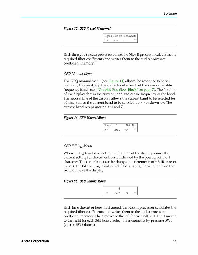
Figure 13. GEQ Preset Menu—Hi
Each time you select a preset response, the Nios II processor calculates the required filter coefficients and writes them to the audio processor coefficient memory.
GEQ Manual Menu
The GEQ manual menu (see Figure 14) allows the response to be set manually by specifying the cut or boost in each of the seven available frequency bands (see “Graphic Equalizer Block” on page 7). The first line of the display shows the current band and centre frequency of the band. The second line of the display allows the current band to be selected for editing Sel or the current band to be scrolled up -> or down <-. The current band wraps around at 1 and 7.
Figure 14. GEQ Manual Menu
GEQ Editing Menu
When a GEQ band is selected, the first line of the display shows the current setting for the cut or boost, indicated by the position of the # character. The cut or boost can be changed in increments of ± 3dB or reset to 0dB. The 0dB setting is indicated if the # is aligned with the B on the second line of the display.
Figure 15. GEQ Editing Menu
Each time the cut or boost is changed, the Nios II processor calculates the required filter coefficients and writes them to the audio processor coefficient memory. The # moves to the left for each 3dB cut; The # moves to the right for each 3dB boost. Select the increments by pressing SW0 (cut) or SW2 (boost).
Equalizer Preset
Hi <- . ^
Band: 1 50 Hz
<- Sel -> ^
#
-3 0dB +3 ^
Altera Corporation 15Preliminary
Automotive Audio Reference Design
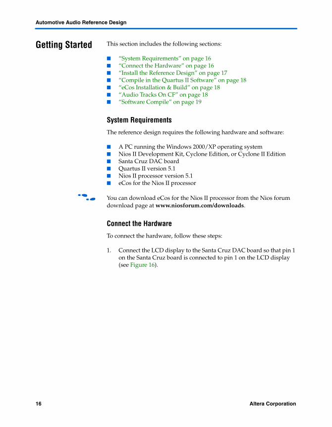
Getting Started This section includes the following sections:
■ “System Requirements” on page 16■ “Connect the Hardware” on page 16■ “Install the Reference Design” on page 17■ “Compile in the Quartus II Software” on page 18■ “eCos Installation & Build” on page 18■ “Audio Tracks On CF” on page 18■ “Software Compile” on page 19
System Requirements
The reference design requires the following hardware and software:
■ A PC running the Windows 2000/XP operating system■ Nios II Development Kit, Cyclone Edition, or Cyclone II Edition■ Santa Cruz DAC board■ Quartus II version 5.1■ Nios II processor version 5.1■ eCos for the Nios II processor
f You can download eCos for the Nios II processor from the Nios forum download page at www.niosforum.com/downloads.
Connect the Hardware
To connect the hardware, follow these steps:
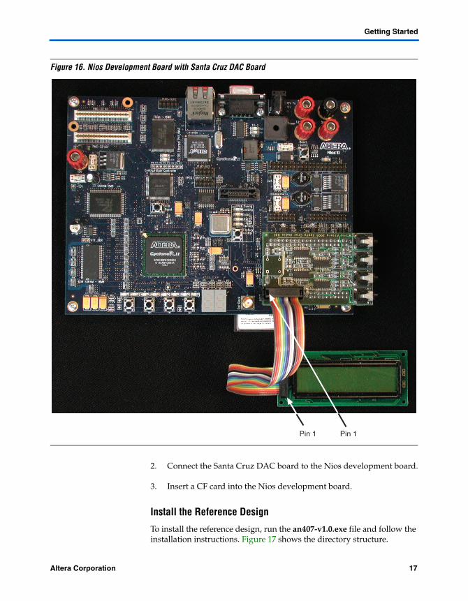
1. Connect the LCD display to the Santa Cruz DAC board so that pin 1 on the Santa Cruz board is connected to pin 1 on the LCD display (see Figure 16).
16 Altera CorporationPreliminary
Getting Started
Figure 16. Nios Development Board with Santa Cruz DAC Board
2. Connect the Santa Cruz DAC board to the Nios development board.
3. Insert a CF card into the Nios development board.
Install the Reference Design
To install the reference design, run the an407-v1.0.exe file and follow the installation instructions. Figure 17 shows the directory structure.
Pin 1 Pin 1
Altera Corporation 17Preliminary
Automotive Audio Reference Design
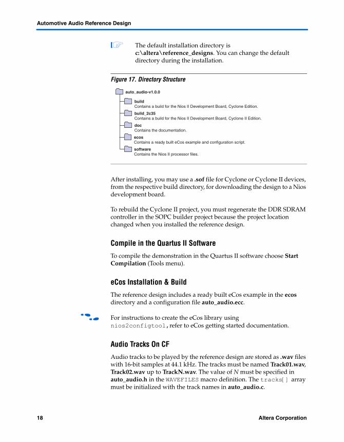
1 The default installation directory is c:\altera\reference_designs. You can change the default directory during the installation.
Figure 17. Directory Structure
After installing, you may use a .sof file for Cyclone or Cyclone II devices, from the respective build directory, for downloading the design to a Nios development board.
To rebuild the Cyclone II project, you must regenerate the DDR SDRAM controller in the SOPC builder project because the project location changed when you installed the reference design.
Compile in the Quartus II Software
To compile the demonstration in the Quartus II software choose Start Compilation (Tools menu).
eCos Installation & Build
The reference design includes a ready built eCos example in the ecos directory and a configuration file auto_audio.ecc.
f For instructions to create the eCos library using nios2configtool,refer to eCos getting started documentation.
Audio Tracks On CF
Audio tracks to be played by the reference design are stored as .wav files with 16-bit samples at 44.1 kHz. The tracks must be named Track01.wav, Track02.wav up to TrackN.wav. The value of N must be specified in auto_audio.h in the WAVEFILES macro definition. The tracks[] array must be initialized with the track names in auto_audio.c.
docContains the documentation.
build_2c35Contains a build for the Nios II Development Board, Cyclone II Edition.
buildContains a build for the Nios II Development Board, Cyclone Edition.
ecosContains a ready built eCos example and configuration script.
auto_audio-v1.0.0
softwareContains the Nios II processor files.
18 Altera CorporationPreliminary
Getting Started
Software Compile
The reference design software uses a Nios II IDE advanced C++ project to compile the eCos library and the reference design source code.
To rebuild the software project, follow these steps:
4. Open the Nios II IDE by choosing Start > All Progams > Altera > Nios II version > Nios II IDE.
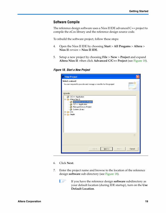
5. Setup a new project by choosing File > New > Project and expand Altera Nios II >then click Advanced C/C++ Project (see Figure 18).
Figure 18. Start a New Project
6. Click Next.
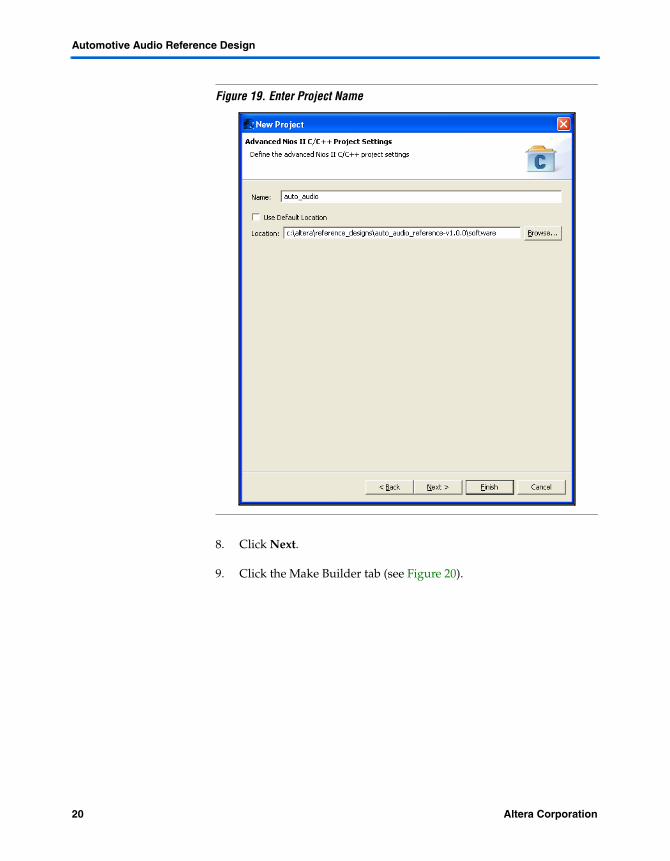
7. Enter the project name and browse to the location of the reference design software sub-directory (see Figure 18).
1 If you have the reference design software subdirectory as your default location (during IDE startup), turn on the Use Default Location.
Altera Corporation 19Preliminary
Automotive Audio Reference Design
Figure 19. Enter Project Name
8. Click Next.
9. Click the Make Builder tab (see Figure 20).
20 Altera CorporationPreliminary
Resource Usage
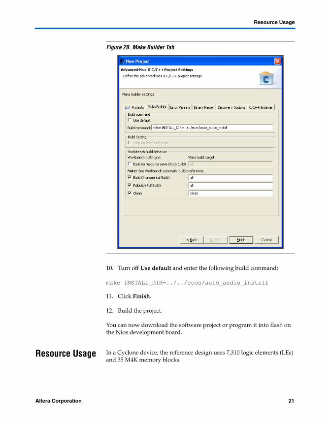
Figure 20. Make Builder Tab
10. Turn off Use default and enter the following build command:
make INSTALL_DIR=../../ecos/auto_audio_install
11. Click Finish.
12. Build the project.
You can now download the software project or program it into flash on the Nios development board.
Resource Usage In a Cyclone device, the reference design uses 7,310 logic elements (LEs) and 35 M4K memory blocks.
Altera Corporation 21Preliminary
Automotive Audio Reference Design
In a Cyclone II device, the reference design uses 6,686 LEs, 11 embedded multiplier elements (9 × 9), and 36 M4K blocks.
References This application note uses the following references:
■ TLV320DAC23 Stereo Audio D/A Converter, 8- to 96-kHz With Integrated Headphone Amplifier Data Manual, Texas Instruments February 2004, SLES001C
■ I2S Bus Specification, Phillips Semiconductors, June 1996
22 Altera CorporationPreliminary
101 Innovation DriveSan Jose, CA 95134(408) 544-7000www.altera.comApplications Hotline:(800) 800-EPLDLiterature Services:[email protected]
Copyright © 2006 Altera Corporation. All rights reserved. Altera, The Programmable Solutions Company,the stylized Altera logo, specific device designations, and all other words and logos that are identified astrademarks and/or service marks are, unless noted otherwise, the trademarks and service marks of AlteraCorporation in the U.S. and other countries. All other product or service names are the property of their re-spective holders. Altera products are protected under numerous U.S. and foreign patents and pendingapplications, maskwork rights, and copyrights. Altera warrants performance of its semiconductor productsto current specifications in accordance with Altera's standard warranty, but reserves the right to make chang-es to any products and services at any time without notice. Altera assumes no responsibility or liabilityarising out of the application or use of any information, product, or service describedherein except as expressly agreed to in writing by Altera Corporation. Altera customersare advised to obtain the latest version of device specifications before relying on any pub-lished information and before placing orders for products or services.