Embed Size (px)
DESCRIPTION
File
Citation preview
5
Introduction to
Automobile Engineering UNIT 1 INTRODUCTION TO AUTOMOBILE
ENGINEERING
Structure
1.1 Introduction
Objectives
1.2 Definition
1.3 Classification of Vehicles
1.4 Layout of an Automobile Chassis
1.5 Components of the Automobile
1.6 Functions of Major Components of an Automobile
1.7 Summary
1.8 Key Words
1.9 Answers to SAQs
1.1 INTRODUCTION
Automobile engineering is the one of the stream of mechanical engineering. It deals with
the various types of automobiles, their mechanism of transmission systems and its
applications. Automobiles are the different types of vehicles used for transportation of
passengers, goods, etc. Basically all the types of vehicles works on the principle of
internal combustion processes or some times the engines are called as internal
combustion engines. Different types of fuels are burnt inside the cylinder at higher
temperature to get the transmission motion in the vehicles. Most of the automobiles are
internal combustion engines vehicles only. Therefore, every mechanical and automobile
engineers should have the knowledge of automobile engineering its mechanism and its
various applications.
Objectives
After studying this unit, you should be able to
define automobile engineering,
classify the vehicles,
list the various components of automobile, and
describes the function of components of automobile.
1.2 DEFINITION
Automobile engineering is a branch of engineering which deals with everything about
automobiles and practices to propel them.
Automobile is a vehicle driven by an internal combustion engine and it is used for
transportation of passengers and goods on the ground. Automobile can also be defined as
a vehicle which can move by itself.
Examples : Car, jeep, bus, truck, scooter, etc.
6
Automobile Engineering
1.3 CLASSIFICATION OF VEHICLES
Automobiles or vehicles can be classified on different bases as given below :
On the Basis of Load
(a) Heavy transport vehicle (HTV) or heavy motor vehicle (HMV), e.g. trucks,
buses, etc.
(b) Light transport vehicle (LTV), e.g. pickup, station wagon, etc.
(c) Light motor vehicle (LMV), e.g. cars, jeeps, etc.
Wheels
(a) Two wheeler vehicle, for example : Scooter, motorcycle, scooty, etc.
(b) Three wheeler vehicle, for example : Autorickshaw, three wheeler scooter
for handicaps and tempo, etc.
(c) Four wheeler vehicle, for example : Car, jeep, trucks, buses, etc.
(d) Six wheeler vehicle, for example : Big trucks with two gear axles each
having four wheels.
Fuel Used
(a) Petrol vehicle, e.g. motorcycle, scooter, cars, etc.
(b) Diesel vehicle, e.g. trucks, buses, etc.
(c) Electric vehicle which use battery to drive.
(d) Steam vehicle, e.g. an engine which uses steam engine. These engines are
now obsolete.
(e) Gas vehicle, e.g. LPG and CNG vehicles, where LPG is liquefied petroleum
gas and CNG is compressed natural gas.
Body
On the basis of body, the vehicles are classified as :
(a) Sedan with two doors
(b) Sedan with four doors
(c) Station wagon
(d) Convertible, e.g. jeep, etc.
(e) Van
(f) Special purpose vehicle, e.g. ambulance, milk van, etc.
Transmission
(a) Conventional vehicles with manual transmission, e.g. car with 5 gears.
(b) Semi-automatic
(c) Automatic : In automatic transmission, gears are not required to be changed
manually. It is automatically changes as per speed of the automobile.
Position of Engine
Engine in Front
Most of the vehicles have engine in the front. Example : most of the cars,
buses, trucks in India.
Engine in the Rear Side
Very few vehicles have engine located in the rear. Example : Nano car.
7
Introduction to
Automobile Engineering 1.4 LAYOUT OF AN AUTOMOBILE CHASIS
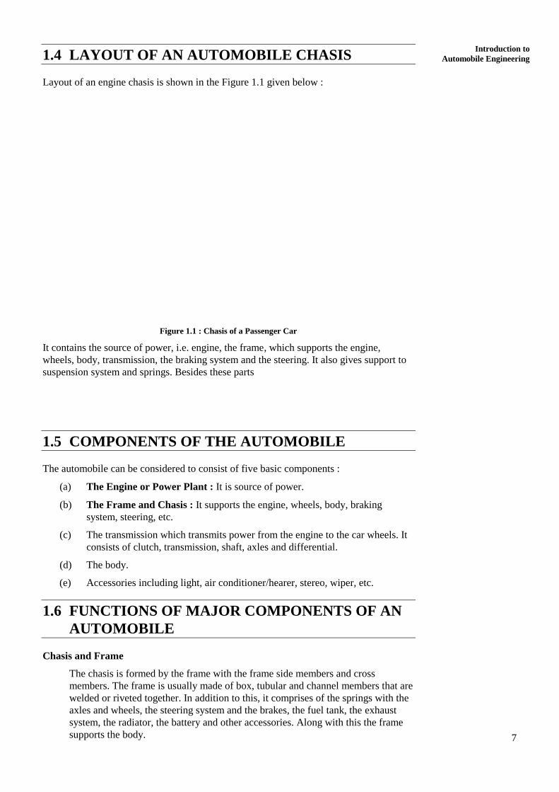
Layout of an engine chasis is shown in the Figure 1.1 given below :
Figure 1.1 : Chasis of a Passenger Car
It contains the source of power, i.e. engine, the frame, which supports the engine,
wheels, body, transmission, the braking system and the steering. It also gives support to
suspension system and springs. Besides these parts
1.5 COMPONENTS OF THE AUTOMOBILE
The automobile can be considered to consist of five basic components :
(a) The Engine or Power Plant : It is source of power.
(b) The Frame and Chasis : It supports the engine, wheels, body, braking
system, steering, etc.
(c) The transmission which transmits power from the engine to the car wheels. It
consists of clutch, transmission, shaft, axles and differential.
(d) The body.
(e) Accessories including light, air conditioner/hearer, stereo, wiper, etc.
1.6 FUNCTIONS OF MAJOR COMPONENTS OF AN
AUTOMOBILE
Chasis and Frame
The chasis is formed by the frame with the frame side members and cross
members. The frame is usually made of box, tubular and channel members that are
welded or riveted together. In addition to this, it comprises of the springs with the
axles and wheels, the steering system and the brakes, the fuel tank, the exhaust
system, the radiator, the battery and other accessories. Along with this the frame
supports the body.
8
Automobile Engineering
Engine or Power Plant
The engine is the power plant of the vehicle. In general, internal combustion
engine with petrol or diesel fuel is used to run a vehicle. An engine may be either
a two-stroke engine or a four-stroke engine.
An engine consists of a cylinder, piston, valves, valve operating mechanism,
carburetor (or MPFI in modern cars), fan, fuel feed pump and oil pump, etc.
Besides this, an engine requires ignition system for burning fuel in the engine
cylinder.
Transmission System (Clutch and Gear Box)
The power developed by the engine is transferred to the wheels by transmission
system. Transmission system must do three jobs :
(a) It must provide varying gear ratios. Number of gear ratios are equal to
number of gears in a vehicle.
(b) It must provide a reverse gear for moving vehicle in reverse direction.
(c) It must provide a neutral or disconnecting arrangement so that the
engine can be uncoupled from the wheels of the vehicle. In a
conventional transmission system, there is a clutch, a manually
operated transmission (gear box), a propeller shaft and a differential
or final drive.
Clutch
The purpose of the clutch is to allow the driver to couple or decouple the engine
and transmission. When clutch is in engaged position, the engine power flows to
the transmission through it (clutch). When gears are to be changed while vehicle is
running, the clutch permits temporary decoupling of engine and wheels so that
gears can be shifted. In a scooter, the clutch is operated by hand where as in a car
the clutch is operated by foot. It is necessary to interrupt the flow of power before
gears are changed. Without a clutch, it will by very difficult.
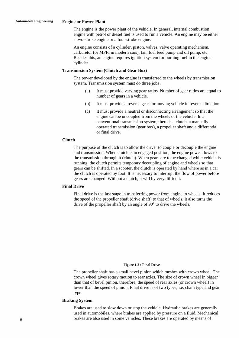
Final Drive
Final drive is the last stage in transferring power from engine to wheels. It reduces
the speed of the propeller shaft (drive shaft) to that of wheels. It also turns the
drive of the propeller shaft by an angle of 90o to drive the wheels.
Figure 1.2 : Final Drive
The propeller shaft has a small bevel pinion which meshes with crown wheel. The
crown wheel gives rotary motion to rear axles. The size of crown wheel in bigger
than that of bevel pinion, therefore, the speed of rear axles (or crown wheel) in
lower than the speed of pinion. Final drive is of two types, i.e. chain type and gear
type.
Braking System
Brakes are used to slow down or stop the vehicle. Hydraulic brakes are generally
used in automobiles, where brakes are applied by pressure on a fluid. Mechanical
brakes are also used in some vehicles. These brakes are operated by means of
9
Introduction to
Automobile Engineering leavers, linkages, pedals, cams, etc. Hand brake or parking brake is usually a
mechanical brake. These are used for parking the vehicles on sloppy surfaces and
also in case of emergency.
Gear Box
Gear box contain gearing arrangement to get different speeds. Gears are used to
get more than one speed ratios. When both mating gears have same number of
teeth, both will rotate at same number speed. But when one gear has less teeth
than other, the gear with less number of teeth will rotate faster than larger gear. In
a typical car, there may be six gears including one reverse gear. First gear gives
low speed but high torque. Higher gears give progressively increasing speeds.
Gears are engaged and disengaged by a shift lever.
Steering System
In front wheels can be turned to left and right by steering system so that the
vehicle can be steered. The steering wheel is placed in front of driver. It is
mechanically linked to the wheels to provide the steering control. The primary
function of the steering system is to provide angular motion to front wheels so that
vehicle can negotiate a turn. It also provides directional stability to vehicle when
the vehicle moves ahead in straight line.
Figure 1.3 : Simple Driving of a Steering System
Now-a-days, many vehicles are equipped with power steering which uses pressure
of a fluid to reduce steering effort. When driver turns the steering wheel, a
hydraulic mechanism comes into play to provide most of the effort needed to turn
the wheel.
Front Axle
Front axles are mounted at the end of front axle. A part of the weight of vehicle is
transmitted to the wheels through this axle. The front axle performs several
functions.
It carries the weight of the front of the vehicle and also takes horizontal and
vertical loads when vehicle moves on bumpy roads. When brakes are provided on
front wheels, it endures bending stresses and torsional stresses. It is generally
made from steel drop forging. It is robust in construction.
Suspension System
Suspension system of an automobile separates the wheel and axle assembly of the
automobile from its body. Main function of the suspension system is to isolate the
body of the vehicle from shocks and vibrations generated due to irregularities on
the surface of roads. Shock absorbers are provided in the vehicles for this purpose.
It is in the form of spring and damper. The suspension system is provided both on
front end and rear end of the vehicle.
A suspension system also maintains the stability of the vehicle in pitching or
rolling when vehicle is in motion.
10
Automobile Engineering
SAQ 1
(a) Define automobile engineering.
(b) Classify the vehicles on the basis of different aspects.
(c) What are the various components of automobile?
(d) Describe the functions of various components of automobile.
(e) Describe the working of steering system mechanism
1.7 SUMMARY
1.8 KEY WORDS
1.9 ANSWERS TO SAQs
Refer the preceding text for all the Answers to SAQs.
11
Power Plants
UNIT 2 POWER PLANTS
Structure
2.1 Introduction
Objectives
2.2 Classification of IC Engines
2.3 Four Stroke Engines versus Two Stroke Engines
2.4 Working of Four Stroke Petrol Engine
2.5 Working of Four Stroke Diesel Engines
2.6 Working of Two Stroke Petrol Engines
2.7 Working of Two Stroke Diesel Engines
2.8 Main Differences between Two and Four Stroke Engines
2.9 Application of Two Stroke and Four Stroke Engines
2.10 Important Terms
2.11 Specifications of Automobile Engine
2.12 Summary
2.13 Key Words
2.14 Answers to SAQs
2.1 INTRODUCTION
Power plant or power unit of an automobile is that component or part which produces
power to drive the automobile. It is generally in the form of an internal combustion
engine running on petrol or diesel. In some cases, it can be a gas turbine or steam engine.
These are called external combustion engines. However, steam engines are now obsolete
and therefore not used for driving any vehicle.
This unit mainly covers various aspects of internal combustion engines from concept to
their principle of working. In case of an internal combustion engine (IC engines)
combustion (burning) of fuel with air takes place inside the engine cylinder.
Objectives
After studying this unit, you should be able to
,
,
, and
.
2.2 CLASSIFICATION OF IC ENGINES
IC engines may be classified on different bases. Some of the main classifications are
given below :
According to Fuel Used
(a) Petrol engine
(b) Diesel engine
12
Automobile Engineering
(c) LPG engine
(d) CNG (Compressed Natural Gas) engine
According to Cycle of Operation
(a) Two stroke engines
(b) Four stroke engines
According to Cycle of Combustion
(a) Otto cycle engines which work on Otto cycle.
(b) Diesel cycle engine which work on diesel cycle.
(c) Dual cycle engines which work on dual cycle.
According to Method of Ignition
Spark Ignition (SI) Engines
These engines are petrol engines in which a spark plug is used to ignite the
fuel-air mixture.
Compression Ignition (CI) Engines
Diesel engines are CI engines in which air is compressed to such a high
pressure and temperature so that burning of fuel takes place as soon as it is
injected into the cylinder due to high temperature.
2.3 FOUR STROKE ENGINES VERSUS TWO
STROKE ENGINES
Four stroke engines are those engines in which one engine cycle is completed in two
revolutions of crank shaft or four piston strokes. Various piston strokes are : suction,
compression, power and exhaust.
In two stroke engines, the entire cycle is completed in one revolution of crank shaft or
two piston strokes.
2.4 WORKING OF FOUR STROKE PETROL ENGINE
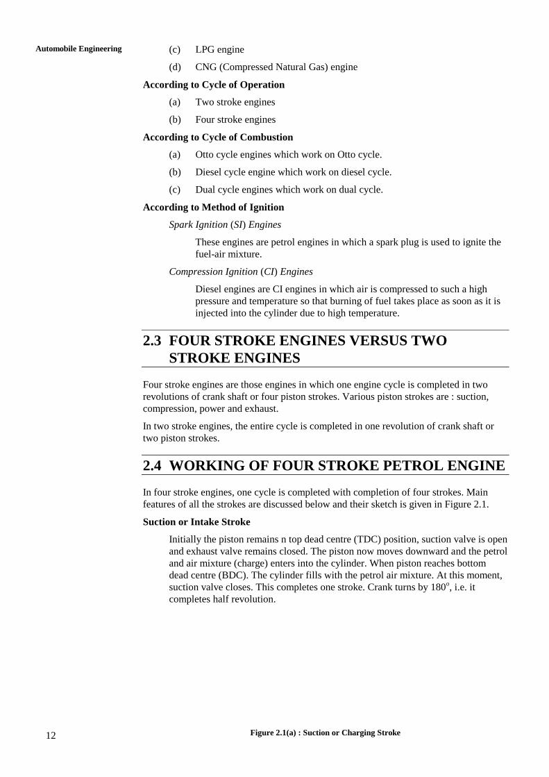
In four stroke engines, one cycle is completed with completion of four strokes. Main
features of all the strokes are discussed below and their sketch is given in Figure 2.1.
Suction or Intake Stroke
Initially the piston remains n top dead centre (TDC) position, suction valve is open
and exhaust valve remains closed. The piston now moves downward and the petrol
and air mixture (charge) enters into the cylinder. When piston reaches bottom
dead centre (BDC). The cylinder fills with the petrol air mixture. At this moment,
suction valve closes. This completes one stroke. Crank turns by 180o, i.e. it
completes half revolution.
Figure 2.1(a) : Suction or Charging Stroke
13
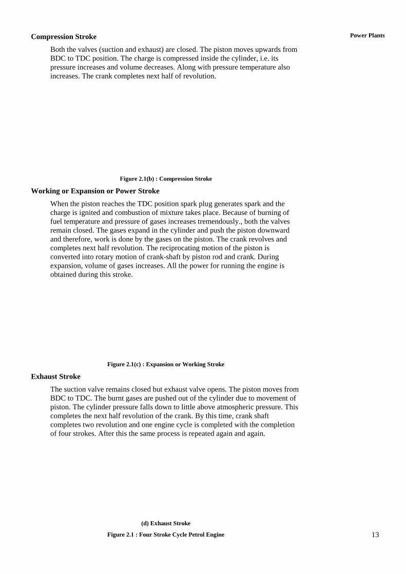
Power Plants Compression Stroke
Both the valves (suction and exhaust) are closed. The piston moves upwards from
BDC to TDC position. The charge is compressed inside the cylinder, i.e. its
pressure increases and volume decreases. Along with pressure temperature also
increases. The crank completes next half of revolution.
Figure 2.1(b) : Compression Stroke
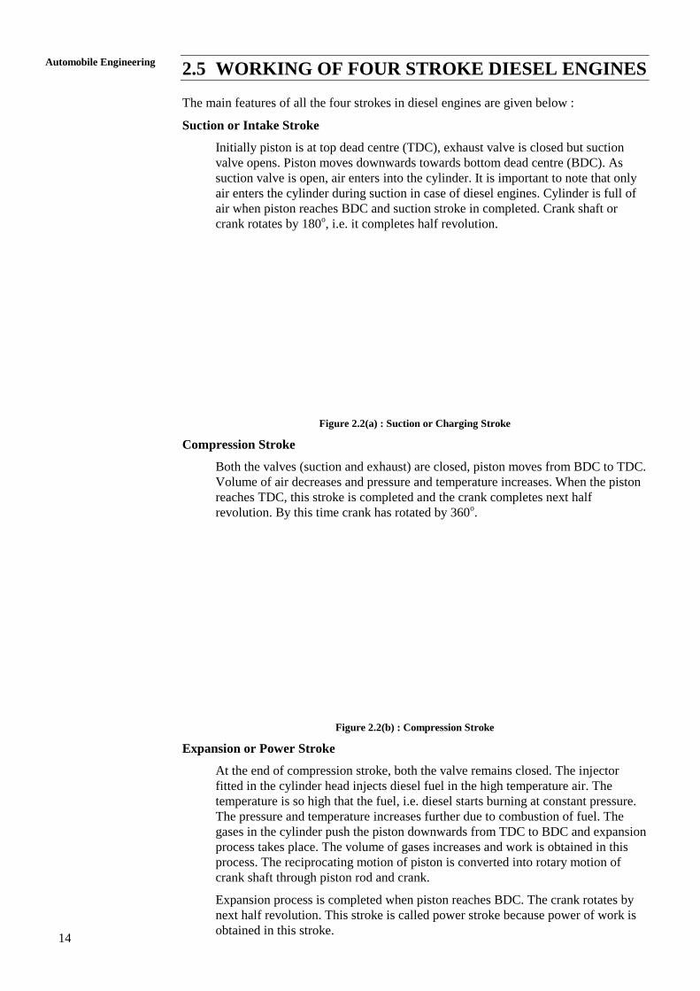
Working or Expansion or Power Stroke
When the piston reaches the TDC position spark plug generates spark and the
charge is ignited and combustion of mixture takes place. Because of burning of
fuel temperature and pressure of gases increases tremendously., both the valves
remain closed. The gases expand in the cylinder and push the piston downward
and therefore, work is done by the gases on the piston. The crank revolves and
completes next half revolution. The reciprocating motion of the piston is
converted into rotary motion of crank-shaft by piston rod and crank. During
expansion, volume of gases increases. All the power for running the engine is
obtained during this stroke.
Figure 2.1(c) : Expansion or Working Stroke
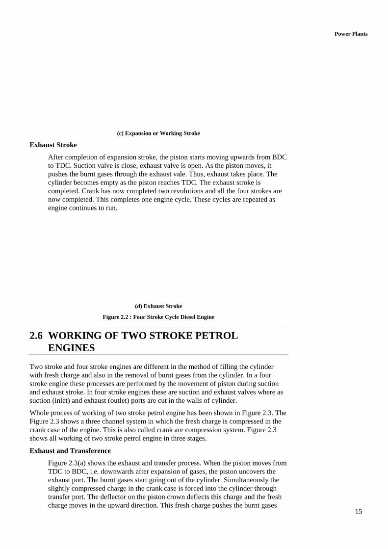
Exhaust Stroke
The suction valve remains closed but exhaust valve opens. The piston moves from
BDC to TDC. The burnt gases are pushed out of the cylinder due to movement of
piston. The cylinder pressure falls down to little above atmospheric pressure. This
completes the next half revolution of the crank. By this time, crank shaft
completes two revolution and one engine cycle is completed with the completion
of four strokes. After this the same process is repeated again and again.
(d) Exhaust Stroke
Figure 2.1 : Four Stroke Cycle Petrol Engine
14
Automobile Engineering
2.5 WORKING OF FOUR STROKE DIESEL ENGINES
The main features of all the four strokes in diesel engines are given below :
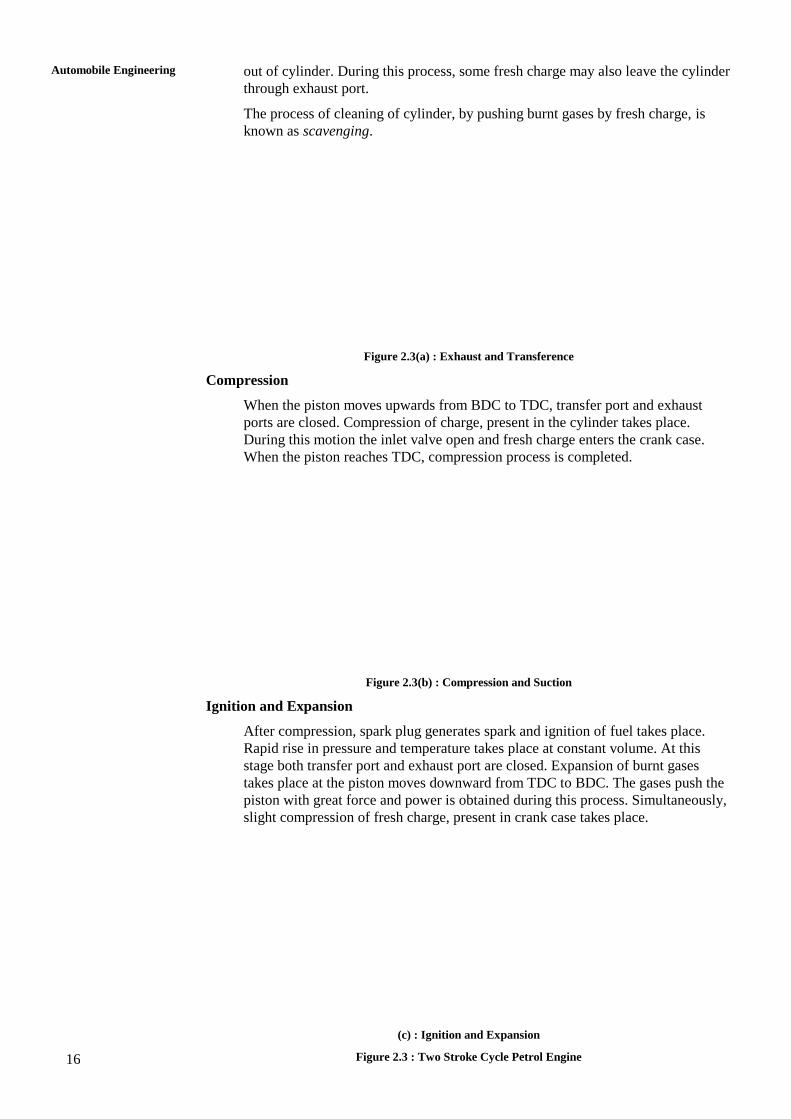
Suction or Intake Stroke
Initially piston is at top dead centre (TDC), exhaust valve is closed but suction
valve opens. Piston moves downwards towards bottom dead centre (BDC). As
suction valve is open, air enters into the cylinder. It is important to note that only
air enters the cylinder during suction in case of diesel engines. Cylinder is full of
air when piston reaches BDC and suction stroke in completed. Crank shaft or
crank rotates by 180o, i.e. it completes half revolution.
Figure 2.2(a) : Suction or Charging Stroke
Compression Stroke
Both the valves (suction and exhaust) are closed, piston moves from BDC to TDC.
Volume of air decreases and pressure and temperature increases. When the piston
reaches TDC, this stroke is completed and the crank completes next half
revolution. By this time crank has rotated by 360o.
Figure 2.2(b) : Compression Stroke
Expansion or Power Stroke
At the end of compression stroke, both the valve remains closed. The injector
fitted in the cylinder head injects diesel fuel in the high temperature air. The
temperature is so high that the fuel, i.e. diesel starts burning at constant pressure.
The pressure and temperature increases further due to combustion of fuel. The
gases in the cylinder push the piston downwards from TDC to BDC and expansion
process takes place. The volume of gases increases and work is obtained in this
process. The reciprocating motion of piston is converted into rotary motion of
crank shaft through piston rod and crank.
Expansion process is completed when piston reaches BDC. The crank rotates by
next half revolution. This stroke is called power stroke because power of work is
obtained in this stroke.
15
Power Plants
(c) Expansion or Working Stroke
Exhaust Stroke
After completion of expansion stroke, the piston starts moving upwards from BDC
to TDC. Suction valve is close, exhaust valve is open. As the piston moves, it
pushes the burnt gases through the exhaust vale. Thus, exhaust takes place. The
cylinder becomes empty as the piston reaches TDC. The exhaust stroke is
completed. Crank has now completed two revolutions and all the four strokes are
now completed. This completes one engine cycle. These cycles are repeated as
engine continues to run.
(d) Exhaust Stroke
Figure 2.2 : Four Stroke Cycle Diesel Engine
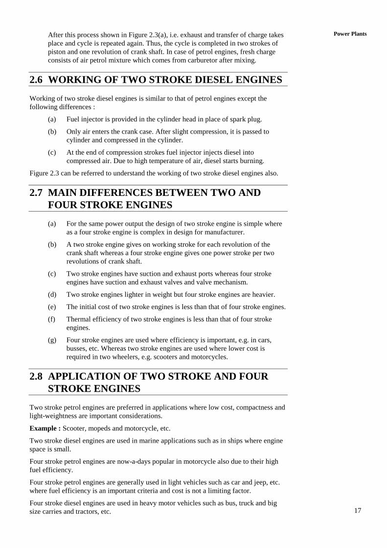
2.6 WORKING OF TWO STROKE PETROL
ENGINES
Two stroke and four stroke engines are different in the method of filling the cylinder
with fresh charge and also in the removal of burnt gases from the cylinder. In a four
stroke engine these processes are performed by the movement of piston during suction
and exhaust stroke. In four stroke engines these are suction and exhaust valves where as
suction (inlet) and exhaust (outlet) ports are cut in the walls of cylinder.
Whole process of working of two stroke petrol engine has been shown in Figure 2.3. The
Figure 2.3 shows a three channel system in which the fresh charge is compressed in the
crank case of the engine. This is also called crank are compression system. Figure 2.3
shows all working of two stroke petrol engine in three stages.
Exhaust and Transference
Figure 2.3(a) shows the exhaust and transfer process. When the piston moves from
TDC to BDC, i.e. downwards after expansion of gases, the piston uncovers the
exhaust port. The burnt gases start going out of the cylinder. Simultaneously the
slightly compressed charge in the crank case is forced into the cylinder through
transfer port. The deflector on the piston crown deflects this charge and the fresh
charge moves in the upward direction. This fresh charge pushes the burnt gases
16
Automobile Engineering
out of cylinder. During this process, some fresh charge may also leave the cylinder
through exhaust port.
The process of cleaning of cylinder, by pushing burnt gases by fresh charge, is
known as scavenging.
Figure 2.3(a) : Exhaust and Transference
Compression
When the piston moves upwards from BDC to TDC, transfer port and exhaust
ports are closed. Compression of charge, present in the cylinder takes place.
During this motion the inlet valve open and fresh charge enters the crank case.
When the piston reaches TDC, compression process is completed.
Figure 2.3(b) : Compression and Suction
Ignition and Expansion
After compression, spark plug generates spark and ignition of fuel takes place.
Rapid rise in pressure and temperature takes place at constant volume. At this
stage both transfer port and exhaust port are closed. Expansion of burnt gases
takes place at the piston moves downward from TDC to BDC. The gases push the
piston with great force and power is obtained during this process. Simultaneously,
slight compression of fresh charge, present in crank case takes place.
(c) : Ignition and Expansion
Figure 2.3 : Two Stroke Cycle Petrol Engine
17
Power Plants After this process shown in Figure 2.3(a), i.e. exhaust and transfer of charge takes
place and cycle is repeated again. Thus, the cycle is completed in two strokes of
piston and one revolution of crank shaft. In case of petrol engines, fresh charge
consists of air petrol mixture which comes from carburetor after mixing.
2.6 WORKING OF TWO STROKE DIESEL ENGINES
Working of two stroke diesel engines is similar to that of petrol engines except the
following differences :
(a) Fuel injector is provided in the cylinder head in place of spark plug.
(b) Only air enters the crank case. After slight compression, it is passed to
cylinder and compressed in the cylinder.
(c) At the end of compression strokes fuel injector injects diesel into
compressed air. Due to high temperature of air, diesel starts burning.
Figure 2.3 can be referred to understand the working of two stroke diesel engines also.
2.7 MAIN DIFFERENCES BETWEEN TWO AND
FOUR STROKE ENGINES
(a) For the same power output the design of two stroke engine is simple where
as a four stroke engine is complex in design for manufacturer.
(b) A two stroke engine gives on working stroke for each revolution of the
crank shaft whereas a four stroke engine gives one power stroke per two
revolutions of crank shaft.
(c) Two stroke engines have suction and exhaust ports whereas four stroke
engines have suction and exhaust valves and valve mechanism.
(d) Two stroke engines lighter in weight but four stroke engines are heavier.
(e) The initial cost of two stroke engines is less than that of four stroke engines.
(f) Thermal efficiency of two stroke engines is less than that of four stroke
engines.
(g) Four stroke engines are used where efficiency is important, e.g. in cars,
busses, etc. Whereas two stroke engines are used where lower cost is
required in two wheelers, e.g. scooters and motorcycles.
2.8 APPLICATION OF TWO STROKE AND FOUR
STROKE ENGINES
Two stroke petrol engines are preferred in applications where low cost, compactness and
light-weightness are important considerations.
Example : Scooter, mopeds and motorcycle, etc.
Two stroke diesel engines are used in marine applications such as in ships where engine
space is small.
Four stroke petrol engines are now-a-days popular in motorcycle also due to their high
fuel efficiency.
Four stroke petrol engines are generally used in light vehicles such as car and jeep, etc.
where fuel efficiency is an important criteria and cost is not a limiting factor.
Four stroke diesel engines are used in heavy motor vehicles such as bus, truck and big
size carries and tractors, etc.
18
Automobile Engineering
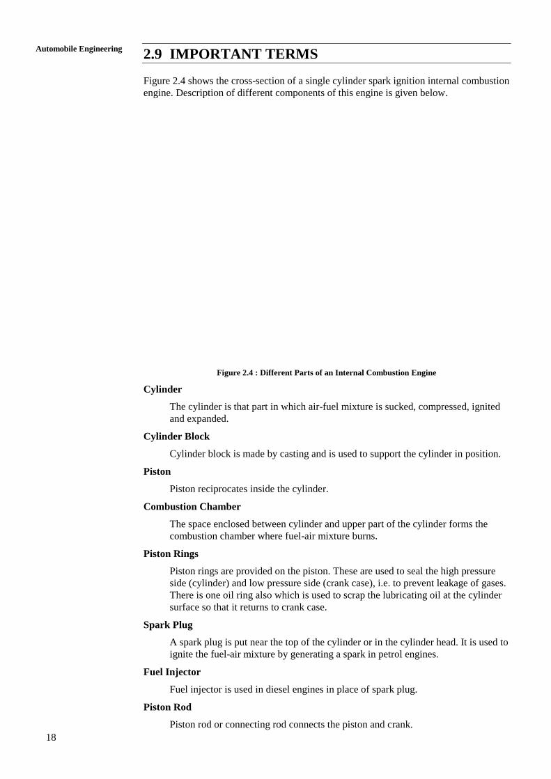
2.9 IMPORTANT TERMS
Figure 2.4 shows the cross-section of a single cylinder spark ignition internal combustion
engine. Description of different components of this engine is given below.
Figure 2.4 : Different Parts of an Internal Combustion Engine
Cylinder
The cylinder is that part in which air-fuel mixture is sucked, compressed, ignited
and expanded.
Cylinder Block
Cylinder block is made by casting and is used to support the cylinder in position.
Piston
Piston reciprocates inside the cylinder.
Combustion Chamber
The space enclosed between cylinder and upper part of the cylinder forms the
combustion chamber where fuel-air mixture burns.
Piston Rings
Piston rings are provided on the piston. These are used to seal the high pressure
side (cylinder) and low pressure side (crank case), i.e. to prevent leakage of gases.
There is one oil ring also which is used to scrap the lubricating oil at the cylinder
surface so that it returns to crank case.
Spark Plug
A spark plug is put near the top of the cylinder or in the cylinder head. It is used to
ignite the fuel-air mixture by generating a spark in petrol engines.
Fuel Injector
Fuel injector is used in diesel engines in place of spark plug.
Piston Rod
Piston rod or connecting rod connects the piston and crank.
19
Power Plants Gudgeon Pin
It is provided on the piston. It joins the piston and connecting rod.
Crank Pin
Crank pin joins the crank and piston rod.
Crank
Crank and the piston rod convert the reciprocating motion of piston into rotary
motion of the crank shaft.
Crank Shaft
It is supported on bearings attached to the crank case.
Crank Case
It is the main body of the engine to which cylinder is connected.
Valve Mechanism
A mechanism to open and close the suction and exhaust valves is also provided in
four stroke engines. This is not shown in Figure 2.4.
Top Dead Centre (TDC)
Top dead center is the upper most position upto which piston moves.
Bottom Dead Centre (BDC)
Bottom dead centre is the lower most position upto which piston comes down.
Bore (D)
Bore is the diameter of piston on cylinder.
Stroke (L)
The nominal distance through which the piston moves from one extreme position
(say TDC) to other extreme position (say BDC).
Suction Manifold
Suction or intake manifold is the pipe through which air and petrol mixture enters
the cylinder (through suction valve).
Exhaust Manifold
Exhaust manifold is the pipe through which burnt gases pass from cylinder
(through exhaust valve) to the silencer of the engine.
Stroke Volume
The volume of the cylinder between TDC and BDC is known as stroke volume.
Clearance Volume
It is the volume of cylinder left above TDC, i.e. between TDC and top of cylinder.
2.10 SPECIFICATIONS OF AUTOMOBILE ENGINE
Engine specifications may include following details :
(a) Model Designation : Model designation as specified by manufacturer.
(b) Engine Configuration : Number of cylinders and their arrangement.
(c) Fuel System : Fuel system with carburetor or with multi-point fuel
injection (MPFI).
20
Automobile Engineering
(d) Displacement Volume : Stroke volume of all cylinders.
(e) Ignition System
(f) Maximum Horse Power
(g) Maximum Torque
Example : Engine Specification of Santro Car.
Model Designation : Hydraulic epsilon engine.
Configuration : In-line-4 cylinder.
Fuel System : Multi-point fuel injection (MPFI).
Displacement : 1086 cc.
Ignition System : Distributorless.
Maximum Horse Power (BHP/rpm) : 63 at 5500 rpm.
Maximum Torque (kgm/rpm) : 9.8 kg at 3000 rpm.
SAQ 1
(a) What do you understand about power plant? Explain.
(b) How do you classify internal combustion (IC) engines? Explain.
(c) Describe the working of two stroke petrol engine with neat diagrams.
(d) Describe the working of four stroke petrol engine with net diagram.
(e) Describe the working of two stroke diesel engine with neat diagram.
2.11 SUMMARY
In this unit, we have learnt the concept of power plant, its applications and types. It is
also called as power unit, used in the automobiles to develop the power. It is also called
as IC engine. This unit also explains the various types of IC engines. The construction
and working of petrol and diesel engines also explained very well. Finally, the unit
concluded with explaining the various terms used n the spark ignition petrol engine.
1.8 KEY WORDS
1.9 ANSWERS TO SAQs
Refer the preceding text for all the Answers to SAQs.
21
Automobile Electrical
Systems UNIT 3 AUTOMOBILE ELECTRICAL
SYSTEMS
Structure
3.1 Introduction
Objectives
3.2 Ignition System
3.3 Requirement of an Ignition System
3.4 Types of Ignition Systems
3.4.1 Battery or Coil Ignition System
3.4.2 Magneto-ignition System
3.4.3 Electronic Ignition System
3.5 Charging System
3.6 Starting System
3.7 Functions of Components used in Circuits
3.7.1 Battery
3.7.2 Ignition or Induction Coil
3.7.3 Contact Breakers
3.7.4 Condenser
3.7.5 Distributor
3.7.6 Ignition Switch
3.7.7 Spark Plugs
3.7.8 Magneto
3.8 Functions and Working Principles of Main Components of Electrical
Systems
3.8.1 Starter
3.8.2 Dynamo or Generator
3.8.3 Alternator or AC Generator
3.8.4 Regulators for Alternator
3.8.5 Regulators for Dynamo
3.8.6 Cutout Relay
3.9 Ignition Timings
3.10 Effect of Ignition Advance and Ignition Retard
3.11 Need of Spark Advance/Retard Mechanisms
3.12 Types of Spark Advance/Retard Mechanisms
3.13 Centrifugal Spark Advance Mechanism
3.14 Vacuum Advance Mechanism
3.15 Summary
3.16 Key Words
3.17 Answers to SAQs
3.1 INTRODUCTION
Automobile electrical system includes starting system, charging system, ignition system
and lighting system and some accessories. The accessories include cigarette lighter horn
and mobile charging system, etc.
22
Automobile Engineering
Major components of a typical electrical systems are given below :
Ignition System
(a) Spark plugs (for petrol vehicle)
(b) Distributor
(c) Ignition coil
(d) Ignition switch, etc.
Charging System
(a) Alternator
(b) Regulator, etc.
Starting System
(a) Battery
(b) Starting motor
(c) Wiring,
(d) Switches, etc.
Objectives
After studying this unit, you should be able to
define electrical system,
understand about major components of the electrical system,
describe the types of ignition systems,
know the starting system of an automobile, and
explain the functions of components used in electrical system circuits.
3.2 IGNITION SYSTEM
In spark ignition engines, a device is required to ignite the compressed air-fuel mixture at
the end of compression stroke. Ignition system fulfills this requirement. It is a part of
electrical system which carries the electric current at required voltage to the spark plug
which generates spark at correct time. It consists of a battery, switch, distributor ignition
coil, spark plugs and necessary wiring.
A compression ignition engine, i.e. a diesel engine does not require any ignition system.
Because, self ignition of fuel air mixture takes place when diesel is injected in the
compressed air at high temperature at the end of compression stroke.
3.3 REQUIREMENTS OF AN IGNITION SYSTEM
(a) The ignition system should be capable of producing high voltage current, as
high as 25000 volts, so that spark plug can produce spark across its
electrode gap.
(b) It should produce spark for sufficient duration so that mixture can be ignited
at all operating speeds of automobile.
(c) Ignition system should function satisfactory at all engine speeds.
(d) Longer life of contact points and spark plug.
23
Automobile Electrical
Systems (e) Spark must generate at correct time at the end of compression stroke in
every cycle of engine operation.
(f) The system must be easy to maintain, light in weight and compact in size.
(g) There should be provision of spark advance with speed and load.
(h) It should be able to function smoothly even when the spark plug electrodes
are deposited with carbon lead or oil.
3.4 TYPES OF IGNITION SYSTEMS
There are three types of ignition systems which are used in petrol engines.
(a) Battery ignition system or coil ignition system.
(b) Magneto ignition system.
(c) Electronic ignition system.
In battery ignition system, the current in the primary winding is supplied by a battery
whereas it is supplied by a magneto in magneto ignition system.
Battery ignition system is used in cars and light truck. Magneto ignition system is used in
some scooters.
Both the systems work on the principle of mutual electromagnetic induction.
Electronic ignition systems use solid state devices such as transistors and capacitors.
3.4.1 Battery or Coil Ignition System
Battery ignition system consists of a battery of 6 or 12 volts, ignition switch, induction
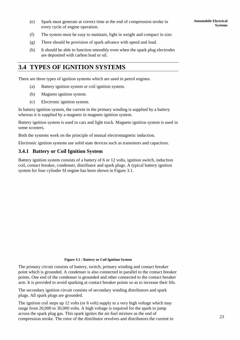
coil, contact breaker, condenser, distributor and spark plugs. A typical battery ignition
system for four cylinder SI engine has been shown in Figure 3.1.
Figure 3.1 : Battery or Coil Ignition System
The primary circuit consists of battery, switch, primary winding and contact breaker
point which is grounded. A condenser is also connected in parallel to the contact breaker
points. One end of the condenser is grounded and other connected to the contact breaker
arm. It is provided to avoid sparking at contact breaker points so as to increase their life.
The secondary ignition circuit consists of secondary winding distributors and spark
plugs. All spark plugs are grounded.
The ignition coil steps up 12 volts (or 6 volt) supply to a very high voltage which may
range from 20,000 to 30,000 volts. A high voltage is required for the spark to jump
across the spark plug gas. This spark ignites the air-fuel mixture as the end of
compression stroke. The rotor of the distributor revolves and distributors the current to
24
Automobile Engineering
the four segments which send the current to different spark plugs. For a 4-cylinder
engine the cam of the contact breaker has four lobes. Therefore, it makes and breaks the
contact of the primary circuit four times in every revolution of cam. Because of which
current is distributed to all the spark plugs in some definite sequence.
The primary winding of ignition coil has less number of turns (e.g. 200 turns) of thick
wire. The secondary winding has relatively large number of turns (e.g. 20,000 turns) of
thin wire.
When ignition switch in turned on, the current flows from battery to the primary
winding. This produces magnetic field in the coil. When the contact point is open, the
magnetic field collapses and the movement of the magnetic field induces current in the
secondary winding of ignition coil. As the number of turns in secondary winding are
more, a very high voltage is produced across the terminals of secondary.
The distributor sends this high voltage to the proper spark plug which generates spark
for ignition of fuel-air mixture. In this way, high voltage current is passed to all spark in
a definite order so that combustion of fuel-air mixture takes place in all cylinders of the
engine.
A ballast register is connected in series in primary circuit to regulate the current. At the
time of starting this register is bypassed so that more current can flow in this circuit.
The breaker points are held by a spring except when they are forced apart by lobes of the
cam.
Advantages
(a) Low initial cost.
(b) Better spark at low speeds and better starting than magneto system.
(c) Reliable system.
(d) No problems due to adjustment of spark timings.
(e) Simpler than magneto system.
Disadvantages
(a) Battery requires periodical maintenance.
(b) In case of battery malfunction, engine cannot be started.
3.4.2 Magneto-ignition System
This system consists of a magneto in place of a battery. So, the magneto produces and
supplies current in primary winding. Rest of the system is same as that in battery ignition
system. A magneto ignition system for a four cylinder SI engine has been shown in
Figure 3.2.
The magneto consists of a fixed armature having primary and secondary windings and a
rotating magnetic assembly. This rotating assembly is driven by the engine.
Rotation of magneto generates current in primary winding having small number of turns.
Secondary winding having large number of turns generates high voltage current which is
supplied to distributor. The distributor sends this current to respective spark plugs. The
magneto may be of rotating armature type or rotating magnet type. In rotating armature
type magneto, the armature having primary and secondary windings and the condenser
rotates between the poles of a stationary horse shoe magnet. In magneto, the magnetic
field is produced by permanent magnets.
Advantages
(a) Better reliability due to absence of battery and low maintenance.
(b) Better suited for medium and high speed engines.
(c) Modern magneto systems are more compact, therefore require less space.
25
Automobile Electrical
Systems Disadvantages
(a) Adjustment of spark timings adversely affects the voltage.
(b) Burning of electrodes is possible at high engine speeds due to high voltage.
(c) Cost is more than that of magneto ignition systems.
Figure 3.2 : Magneto Ignition System
3.4.3 Electronic Ignition Systems
Electronic ignition systems use some solid state devices like transistor and capacitors,
etc. to generate right sparking voltage at right time. These systems have overcome the
limitations of conventional (battery ignition and magneto-ignition) ignition systems.
Modern automobiles make use of these systems. Two systems, common in use, are :
(a) Capacitive discharge ignition, and
(b) Transistorized coil ignition.
These systems are more reliable and require less maintenance. Wear and tear of
components is reduced and life of spark plugs is increased with the use of electronic
ignition.
3.5 CHARGING SYSTEM
Charging system is required to recharge the battery which is an important component of
electrical system of an automobile. Charging is required as the capacity of a battery to
supply current is limited to the energy stored in it in the form of chemical energy.
Battery supplies the current to run the starting motor, various lights and horn, etc.
The charging system generates electricity to recharge the battery and run other electrical
components.
3.5.1 Components of a Charging System
Charging system consists of :
Generator or Dynamo
It converts mechanical energy into electrical energy.
Regulator
It controls the generator output according to the need. It controls the current or
voltage.
Relay
It is used to control the flow of current between generator and battery. It acts as
circuit breaker.
26
Automobile Engineering
3.6 STARTING SYSTEM
The starting system of an automobile is used to start the internal combustion engine.
Both SI and CI engines cannot start by itself. These engines need to be cranked by a
starting motor. This motor is also called a starter or cranking motor. Cranking of any
engine means rotating its crank shaft. Rotation of crank shaft causes the piston to
reciprocate. When piston reciprocates, suction, compression, expansion and exhaust
strokes of engine are completed. Thus, engine completes its working cycle and it starts
running.
Starting motor produces necessary torque to rotate the engine wheel (crank shaft)
through a suitable gear (one pinion on motor and other ring gear around engine wheel).
3.6.1 Components of Starting System
Starting system consists of the following :
(a) Starting Motor : Starting motor to produce rotation of crank shaft.
(b) Drive Mechanism : Drive mechanism to transfer rotary motion of starter to
the crank shaft of the engine.
(c) The ignition switch to start motor.
3.7 FUNCTIONS OF COMPONENTS USED IN
CIRCUITS
Functions of various components used in battery (coil) ignition and magneto-ignition
systems are discussed here in brief.
3.7.1 Battery
It is an important component of electrical system. The battery supplies the necessary
current to the primary winding of ignition coil which is converted into high voltage
current to produce spark. It also supplied current to run the starting motor when engine is
cranked for starting. A battery stores energy in the form of chemical energy and supplies
it for running lights and other accessories of an automobile. Lead-acid battery is
commonly used in most of the automobiles.
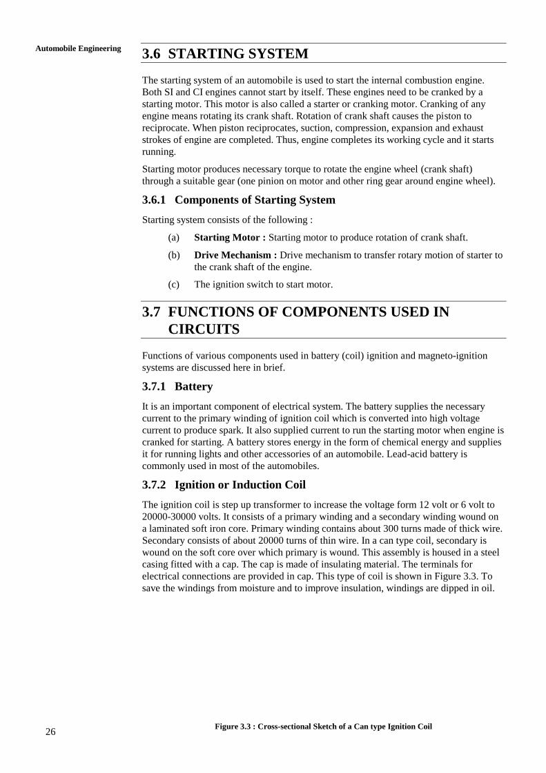
3.7.2 Ignition or Induction Coil
The ignition coil is step up transformer to increase the voltage form 12 volt or 6 volt to
20000-30000 volts. It consists of a primary winding and a secondary winding wound on
a laminated soft iron core. Primary winding contains about 300 turns made of thick wire.
Secondary consists of about 20000 turns of thin wire. In a can type coil, secondary is
wound on the soft core over which primary is wound. This assembly is housed in a steel
casing fitted with a cap. The cap is made of insulating material. The terminals for
electrical connections are provided in cap. This type of coil is shown in Figure 3.3. To
save the windings from moisture and to improve insulation, windings are dipped in oil.
Figure 3.3 : Cross-sectional Sketch of a Can type Ignition Coil
27
Automobile Electrical
Systems One primary terminal is connected to ignition switch and other to the contact breaker.
Secondary terminal is connected to the distributor. The working of ignition coil has been
explained in Section 3.4.1.
3.7.3 Contact Breakers
Contact breaker is required to make contact and break contact of the primary circuit of
ignition system. It consists of two contact breaker points as shown in Figures 3.1 and 3.2.
One point remains fixed while the other can move. A cam is sued to move the movable
point. As cam moves, the contact is made and broken alternately. Primary circuit breaks
when the breaker points open. Magnetic field collapses due to this. This produces high
voltage current in the secondary winding which is supplied to the distributor. This
current is distributor to proper spark plug where it produces spark for ignition of fuel-air
mixture.
3.7.4 Condenser
The function of the condenser in the ignition system is to absorb and store the inductive
current generated in the coil. If condenser is not provided, the induced current will cause
arcing at the breaker points. This will cause burning of the breaker points.
3.7.5 Distributor
The distributor sends the high voltage current, generated in the secondary winding, to the
proper spark plug at proper time. If the automobile is having a four cylinder engine, it
will have four spark plugs.
The cap of the distributor is connected to the secondary winding of coil. It has a rotor
which rotates and comes in contact with the terminals (4 in number for 4 spark plugs)
placed around the rotor. As the rotor comes in contact with the terminals (numbered 1, 2,
3 and 4 in Figures 3.1 and 3.2), the current is passed to the respective spark plug at
proper time when spark is needed.
3.7.6 Ignition Switch
The function of the ignition switch is to connect the battery and starting motor in the
automobiles having self starting system.
Example : In car, jeep, etc.
Its function is to connect battery to induction coil in the battery ignition system.
3.7.7 Spark Plugs
The function of the spark plug is to produce spark between its electrodes. This spark is
used to ignite the fuel-air mixture in the spark ignition (SI) engines.
3.7.8 Magneto
Magneto is used in magneto ignition system. Magneto is a kind of generator to provide
electrical energy to run the ignition system. It is replacement of battery for ignition.
When it is rotated by the engine, it produces high voltage current to be supplied to spark
plugs through the distributor.
3.8 FUNCTIONS AND WORKING PRINCIPLES OF
MAIN COMPONENTS OF ELECTRICAL
SYSTEMS
Functions and principles of starter, dynamo, alternators and regulators have been given
in this section.
28
Automobile Engineering
3.8.1 Starter
It is also known as starting motor or cranking motor. It is used to start heavy engines
which cannot be started by hand cranking.
Function of Starter
IC engines are required to be rotated at some minimum speed after which the
engines starts running by fuel supply. This initial rotation is given by the starting
motor and this is the function of a starter.
Working Principle
A motor converts electrical energy into mechanical energy. Mechanical energy is
obtained in the form of rotation of a wheel. This rotation of a wheel is used to start
the IC engine.
The motor works on the principle that “when a current carrying conductor is put in
a magnetic field, it experiences a mechanical force”. The direction of force is
determined by the Flemming‟s left hand rule.
Flemming’s Left Hand Rule
If we stretch the thumb, forefinger and middle finger such that they are
mutually perpendicular, then according to this rule :
“If the first finger points in the direction of magnetic field and the second
(middle) finger in the direction of current then the thumb will give the
direction of force acting on conductor or the direction of its motion”.
Working of Starter
When the starter switch is put on „on‟ position, the current from battery flows to
starting motor, the motor starts rotating. The motor is connected to the drive unit,
which is used to rotate the engine crank shaft. A small pinion (small gear) is fitted
on the armature shaft of the starting motor. This pinion meshes with the ring gear
when starter rotates. Thus, the fly wheel which is attached to ring gear also starts
revolving. Thus, engine crank shaft starts revolving. With the revolution of crank
shaft, the engine strokes viz. suction, compression, power and exhaust are
completed. Therefore, engine starts running. The starter is engaged to the engine
ring gear (attached to fly wheel) till the engine starts running. As soon as engine
starts running, the starter is disengaged. The starting motor is a low voltage DC
series wounded motor.
3.8.2 Dynamo or Generator
A dynamo is a machine used to convert mechanical used to convert mechanical energy
into electrical energy. When it is driven by the engine it produces electricity for running
all the electrical circuits of the automobile and keeps the battery in charged condition.
This is the function of dynamo.
Principle of Dynamo
“When a conductor moves in a magnetic field, current is produced in it. The
direction of current is determined by Flemming‟s right hand rule”.
Flemming’s Right Hand Rule
If thumb, fore finger and middle finger of right hand are stretched so that
they are mutually perpendicular then the direction of induced current in the
conductor can be found out by this rule.
“If the fore finger indicates the direction of magnetic field and the thumb
shows the direction of motion of the conductor, then middle finger will
indicate the direction induced current”. This is called Flemming‟s right
hand rule.
29
Automobile Electrical
Systems A magnetic field acts between north and south poles of magnets. There are lines of
forces between two poles. When the conductor moves such that lines of force are
cut, current is induced in the conductor. This current can be used to run any
electrical components, e.g. lights and charging system, etc.
The current induced in the conductor depends upon the rate at which force lines
are cut and strength of magnetic field, etc.
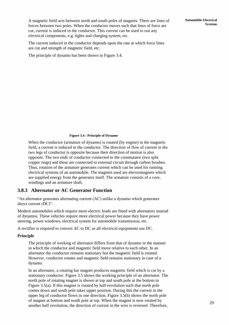
The principle of dynamo has been shown in Figure 3.4.
Figure 3.4 : Principle of Dynamo
When the conductor (armature of dynamo) is rotated (by engine) in the magnetic
field, a current is induced in the conductor. The direction of flow of current in the
two legs of conductor is opposite because their direction of motion is also
opposite. The two ends of conductor connected to the commutator (two split
copper rings) and these are connected to external circuit through carbon brushes.
Thus, rotation of the armature generates current which can be used for running
electrical systems of an automobile. The magnets used are electromagnets which
are supplied energy from the generator itself. The armature consists of a core,
windings and an armature shaft.
3.8.3 Alternator or AC Generator Function
“An alternator generates alternating current (AC) unlike a dynamo which generates
direct current (DC)”.
Modern automobiles which require more electric loads are fitted with alternators instead
of dynamos. These vehicles require more electrical power because they have power
steering, power windows, electrical system for automobile transmission, etc.
A rectifier is required to convert AC to DC as all electrical equipments use DC.
Principle
The principle of working of alternator differs from that of dynamo in the manner
in which the conductor and magnetic field move relative to each other. In an
alternator the conductor remains stationary but the magnetic field is rotated.
However, conductor rotates and magnetic field remains stationary in case of a
dynamo.
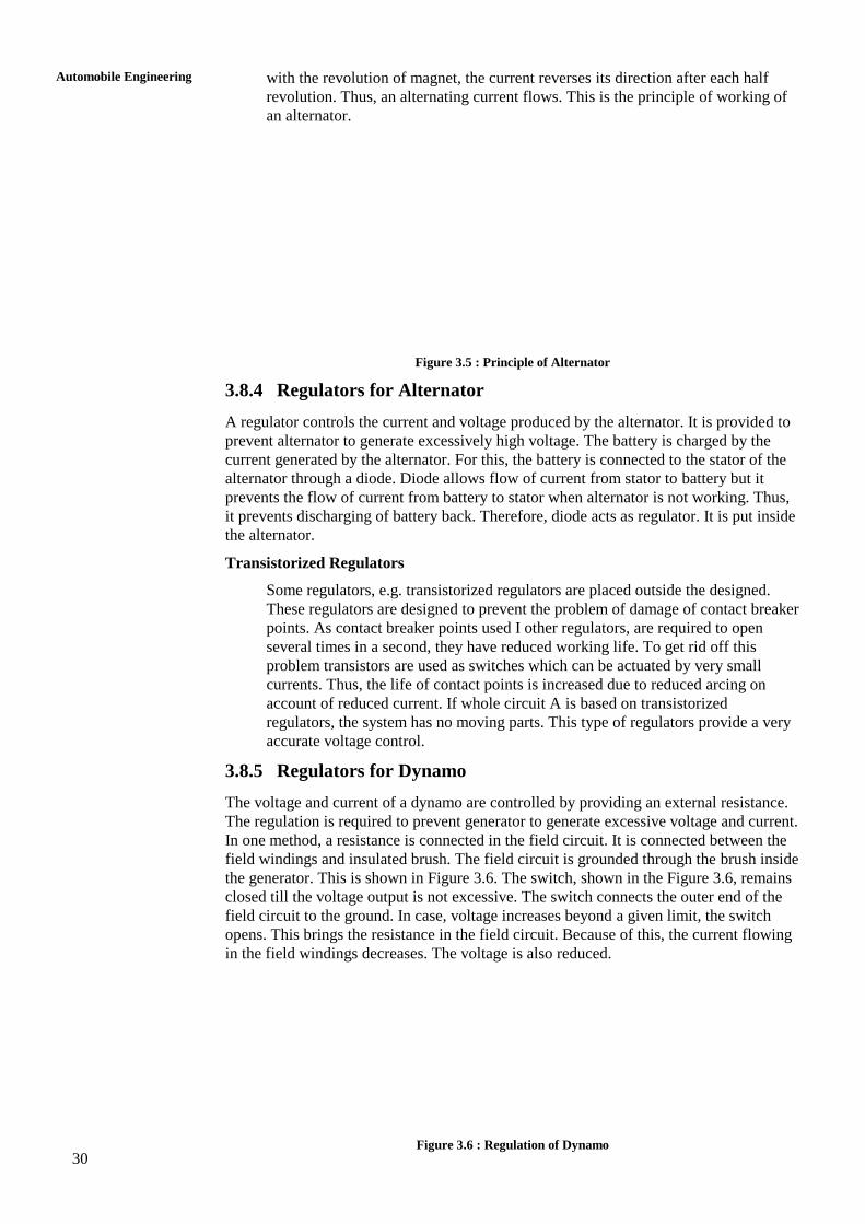
In an alternator, a rotating bar magnet produces magnetic field which is cut by a
stationary conductor. Figure 3.5 shows the working principle of an alternator. The
north pole of rotating magnet is shown at top and south pole at the bottom in
Figure 3.5(a). If this magnet is rotated by half revolution such that north pole
comes down and south pole takes upper position. During this the current in the
upper leg of conductor flows in one direction. Figure 3.5(b) shows the north pole
of magnet at bottom and south pole at top. When the magnet is now rotated by
another half revolution, the direction of current in the wire is reversed. Therefore,
30
Automobile Engineering
with the revolution of magnet, the current reverses its direction after each half
revolution. Thus, an alternating current flows. This is the principle of working of
an alternator.
Figure 3.5 : Principle of Alternator
3.8.4 Regulators for Alternator
A regulator controls the current and voltage produced by the alternator. It is provided to
prevent alternator to generate excessively high voltage. The battery is charged by the
current generated by the alternator. For this, the battery is connected to the stator of the
alternator through a diode. Diode allows flow of current from stator to battery but it
prevents the flow of current from battery to stator when alternator is not working. Thus,
it prevents discharging of battery back. Therefore, diode acts as regulator. It is put inside
the alternator.
Transistorized Regulators
Some regulators, e.g. transistorized regulators are placed outside the designed.
These regulators are designed to prevent the problem of damage of contact breaker
points. As contact breaker points used I other regulators, are required to open
several times in a second, they have reduced working life. To get rid off this
problem transistors are used as switches which can be actuated by very small
currents. Thus, the life of contact points is increased due to reduced arcing on
account of reduced current. If whole circuit A is based on transistorized
regulators, the system has no moving parts. This type of regulators provide a very
accurate voltage control.
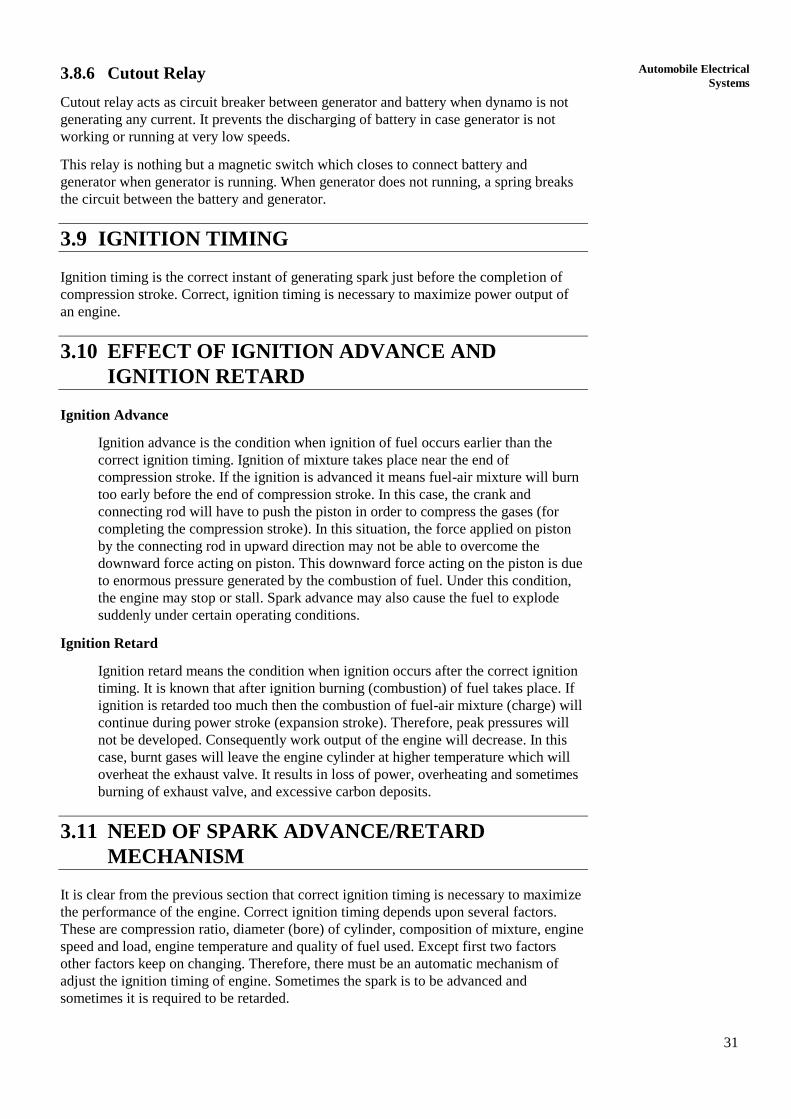
3.8.5 Regulators for Dynamo
The voltage and current of a dynamo are controlled by providing an external resistance.
The regulation is required to prevent generator to generate excessive voltage and current.
In one method, a resistance is connected in the field circuit. It is connected between the
field windings and insulated brush. The field circuit is grounded through the brush inside
the generator. This is shown in Figure 3.6. The switch, shown in the Figure 3.6, remains
closed till the voltage output is not excessive. The switch connects the outer end of the
field circuit to the ground. In case, voltage increases beyond a given limit, the switch
opens. This brings the resistance in the field circuit. Because of this, the current flowing
in the field windings decreases. The voltage is also reduced.
Figure 3.6 : Regulation of Dynamo
31
Automobile Electrical
Systems 3.8.6 Cutout Relay
Cutout relay acts as circuit breaker between generator and battery when dynamo is not
generating any current. It prevents the discharging of battery in case generator is not
working or running at very low speeds.
This relay is nothing but a magnetic switch which closes to connect battery and
generator when generator is running. When generator does not running, a spring breaks
the circuit between the battery and generator.
3.9 IGNITION TIMING
Ignition timing is the correct instant of generating spark just before the completion of
compression stroke. Correct, ignition timing is necessary to maximize power output of
an engine.
3.10 EFFECT OF IGNITION ADVANCE AND
IGNITION RETARD
Ignition Advance
Ignition advance is the condition when ignition of fuel occurs earlier than the
correct ignition timing. Ignition of mixture takes place near the end of
compression stroke. If the ignition is advanced it means fuel-air mixture will burn
too early before the end of compression stroke. In this case, the crank and
connecting rod will have to push the piston in order to compress the gases (for
completing the compression stroke). In this situation, the force applied on piston
by the connecting rod in upward direction may not be able to overcome the
downward force acting on piston. This downward force acting on the piston is due
to enormous pressure generated by the combustion of fuel. Under this condition,
the engine may stop or stall. Spark advance may also cause the fuel to explode
suddenly under certain operating conditions.
Ignition Retard
Ignition retard means the condition when ignition occurs after the correct ignition
timing. It is known that after ignition burning (combustion) of fuel takes place. If
ignition is retarded too much then the combustion of fuel-air mixture (charge) will
continue during power stroke (expansion stroke). Therefore, peak pressures will
not be developed. Consequently work output of the engine will decrease. In this
case, burnt gases will leave the engine cylinder at higher temperature which will
overheat the exhaust valve. It results in loss of power, overheating and sometimes
burning of exhaust valve, and excessive carbon deposits.
3.11 NEED OF SPARK ADVANCE/RETARD
MECHANISM
It is clear from the previous section that correct ignition timing is necessary to maximize
the performance of the engine. Correct ignition timing depends upon several factors.
These are compression ratio, diameter (bore) of cylinder, composition of mixture, engine
speed and load, engine temperature and quality of fuel used. Except first two factors
other factors keep on changing. Therefore, there must be an automatic mechanism of
adjust the ignition timing of engine. Sometimes the spark is to be advanced and
sometimes it is required to be retarded.
32
Automobile Engineering
3.12 TYPES OF SPARK ADVANCE/RETARD
MECHANISMS
Two automatic advance mechanisms are used for spark advance and retard in engines
depending on engine speed and other operating conditions :
(a) Centrifugal spark advance mechanism.
(b) Vacuum spark advance mechanism.
Ignition timing is first set manually. After this these mechanisms are used to modify it
suitably.
3.13 CENTRIFUGAL SPARK ADVANCE
MECHANISM
This mechanism consists of two fly weights, a base plate, cam and a spring. Fly weights
are also called advance weights. The base plate is fixed to the drive shaft. The fly
weights are rotated by distributor drive shaft through the base plate. The weights are
pivoted on the base plate and also attached to the cam with the help of springs. The cam
is also joined with the distributor shaft through springs, flywheel and plate. If engine
speed increases, the fly weights are displaced out radially due to centrifugal force acting
on it. Movement of weights causes the ignition advance (spark advance). At low speeds
there is no advance while it is full advance of very high speeds. (Kindly refer to figure is
standard text book).
3.14 VACUUM ADVANCE MECHANISM
Vacuum advance mechanism consists of a diaphragm whose movement automatically
advances and retards the ignition depending upon engine speed and other operating
conditions. On side of diaphragm is connected to the induction manifold and other side
is connected to atmosphere. (Induction manifold is at lower pressure than atmospheric
and this pressure depends upon engine speed). The diaphragm is connected to the
distributor through a linkage. As engine speed increases the pressure on one side of
diaphragm decreases. This change in pressure controls the movement of diaphragm
which ultimately controls the ignition timings. At normal position of diaphragm the
ignition timing is set at fully retarded position. As engine speed increases the ignition
timings are advanced. Vacuum advance mechanism takes more care of engine load and
less of speed where as centrifugal advance mechanism takes more care of engine speed
and less of load. The scheme of vacuum advance mechanism is shown in Figure 3.7.
Figure 3.7 : Block Diagram of Vacuum Advance Mechanism
33
Automobile Electrical
Systems SAQ 1
(a) Describe the requirements of an ignition system of a SI engine.
(b) List different type of ignition system. Describe the working of battery
ignition system with the help of a suitable diagram.
(c) Draw a neat sketch of magneto ignition system and explain its working.
(d) List various advantages and disadvantages of battery ignition system.
(e) Give a brief description and functions of different components of a charging
system of an automobile.
SAQ 2
(a) Describe the function and working of ignition coil.
(b) Describe in brief the function of a distributor.
(c) Describe in brief the functions of the following components of an ignition
system :
(i) Condenser
(ii) Spark plugs
(iii) Magneto
(iv) Ignition switch
(d) Describe the working principle of starter of an automobile.
(e) Write the function of a dynamo of an automobile and explain its working
principle with the help of a neat sketch.
(f) How does an alternator works? Explain.
SAQ 3
(a) What are the functions of a regulator for an alternator? How does it work?
(b) How does a regulator for dynamo works?
(c) What are different effects of ignition retard on the performance of an
automobile?
(d) What happens to the performance of a vehicle due to ignition advance?
(e) How does centrifugal advance mechanism works?
(f) What is the working principle of vacuum advance mechanism?
34
Automobile Engineering
3.15 SUMMARY
Every student, who is studying the course automobile engineering, must have the
knowledge of transmission system of an automobile. Transmission system is nothing but
transmitting the power from engine to the wheels transfer clutch and gear mechanisms.
So, in this unit, we have studied about the transmission system of automobile. The
transmission system mainly comprises of clutch and gear mechanisms. We have learnt
about the functions and types of clutches and gear boxes. Clutch is mainly used to
yougase or disagause the engine to the transmission or gear box. Gear box is used to
varying the speeds of automobile according to the required conditions or according to the
need of the persons, who are driving the automobile.
3.16 KEY WORDS
3.17 ANSWERS TO SAQs
Refer the preceding text for all the Answers to SAQs.
35
Transmission
UNIT 4 TRANSMISSION
Structure
4.1 Introduction
Objectives
4.2 Clutch
4.3 Principles of Clutch
4.4 Main Parts of a Clutch
4.5 Types of Clutch
4.6 Single Plate Clutch
4.7 Multiple Clutch
4.8 Clutch Pedal Free-play Adjustment
4.9 Function of Gear Box
4.10 Types of Gear Box
4.11 Sliding Mesh Gear Box
4.12 Constant Mesh Gear Box
4.13 Gear Trains
4.14 Types of Gear Trains
4.15 Summary
4.16 Key Words
4.17 Answers to SAQs
4.1 INTRODUCTION
Transmission is the mechanism which is used to transfer the power developed by engine
to the wheels of an automobile.
The transmission system of an automobile includes clutch, gear box, propeller shaft axle
and wheels, etc.
Description of various types of clutches and gear boxes has been given in the following
sections of this unit. The term ‘Transmission’ is used for a device which is located
between clutch and propeller shaft. It may be a gear box, an over drive or a torque
converter, etc.
Objectives
After studying this unit, you should be able to
understand the transmission system of automobiles,
list out the components of the transmission system,
describe the various functions and types of clutches and gear boxes, and
explain the advantages of clutches and gear box.
4.2 CLUTCH
Clutch is used to engage or disengage the engine to the transmission or gear box. When
the clutch is in engaged position, the engine power or rotary motion of engine crankshaft
36
Automobile Engineering
is transmitted to gear box and then to wheels. When clutch is disengaged, the engine
power does not reach to gear box (and to wheels) although engine is running.
Clutch is also used to allow shifting or changing of gears when vehicle is running. For
shifting gears, clutch is first disengaged then gear is shifted and then clutch is engaged.
Clutch has to be disengaged to stop the vehicle and also at the time of idling.
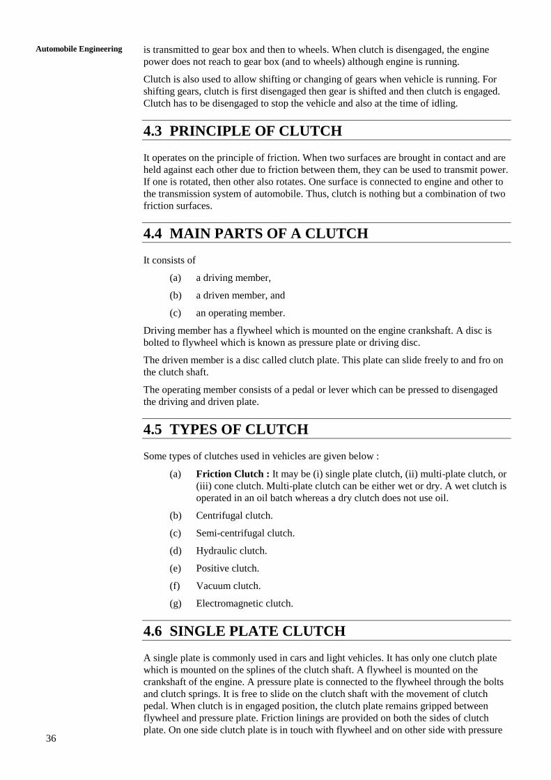
4.3 PRINCIPLE OF CLUTCH
It operates on the principle of friction. When two surfaces are brought in contact and are
held against each other due to friction between them, they can be used to transmit power.
If one is rotated, then other also rotates. One surface is connected to engine and other to
the transmission system of automobile. Thus, clutch is nothing but a combination of two
friction surfaces.
4.4 MAIN PARTS OF A CLUTCH
It consists of
(a) a driving member,
(b) a driven member, and
(c) an operating member.
Driving member has a flywheel which is mounted on the engine crankshaft. A disc is
bolted to flywheel which is known as pressure plate or driving disc.
The driven member is a disc called clutch plate. This plate can slide freely to and fro on
the clutch shaft.
The operating member consists of a pedal or lever which can be pressed to disengaged
the driving and driven plate.
4.5 TYPES OF CLUTCH
Some types of clutches used in vehicles are given below :
(a) Friction Clutch : It may be (i) single plate clutch, (ii) multi-plate clutch, or
(iii) cone clutch. Multi-plate clutch can be either wet or dry. A wet clutch is
operated in an oil batch whereas a dry clutch does not use oil.
(b) Centrifugal clutch.
(c) Semi-centrifugal clutch.
(d) Hydraulic clutch.
(e) Positive clutch.
(f) Vacuum clutch.
(g) Electromagnetic clutch.
4.6 SINGLE PLATE CLUTCH
A single plate is commonly used in cars and light vehicles. It has only one clutch plate
which is mounted on the splines of the clutch shaft. A flywheel is mounted on the
crankshaft of the engine. A pressure plate is connected to the flywheel through the bolts
and clutch springs. It is free to slide on the clutch shaft with the movement of clutch
pedal. When clutch is in engaged position, the clutch plate remains gripped between
flywheel and pressure plate. Friction linings are provided on both the sides of clutch
plate. On one side clutch plate is in touch with flywheel and on other side with pressure
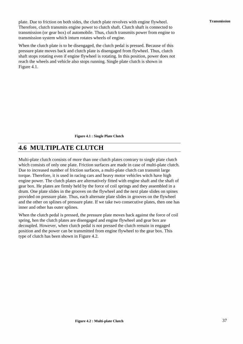
37
Transmission plate. Due to friction on both sides, the clutch plate revolves with engine flywheel.
Therefore, clutch transmits engine power to clutch shaft. Clutch shaft is connected to
transmission (or gear box) of automobile. Thus, clutch transmits power from engine to
transmission system which inturn rotates wheels of engine.
When the clutch plate is to be disengaged, the clutch pedal is pressed. Because of this
pressure plate moves back and clutch plate is disengaged from flywheel. Thus, clutch
shaft stops rotating even if engine flywheel is rotating. In this position, power does not
reach the wheels and vehicle also stops running. Single plate clutch is shown in
Figure 4.1.
Figure 4.1 : Single Plate Clutch
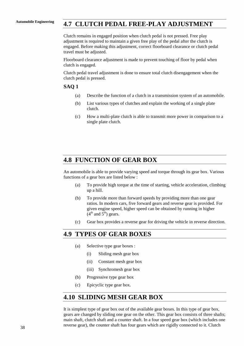
4.6 MULTIPLATE CLUTCH
Multi-plate clutch consists of more than one clutch plates contrary to single plate clutch
which consists of only one plate. Friction surfaces are made in case of multi-plate clutch.
Due to increased number of friction surfaces, a multi-plate clutch can transmit large
torque. Therefore, it is used in racing cars and heavy motor vehicles witch have high
engine power. The clutch plates are alternatively fitted with engine shaft and the shaft of
gear box. He plates are firmly held by the force of coil springs and they assembled in a
drum. One plate slides in the grooves on the flywheel and the next plate slides on spines
provided on pressure plate. Thus, each alternate plate slides in grooves on the flywheel
and the other on splines of pressure plate. If we take two consecutive plates, then one has
inner and other has outer splines.
When the clutch pedal is pressed, the pressure plate moves back against the force of coil
spring, hen the clutch plates are disengaged and engine flywheel and gear box are
decoupled. However, when clutch pedal is not pressed the clutch remain in engaged
position and the power can be transmitted from engine flywheel to the gear box. This
type of clutch has been shown in Figure 4.2.
Figure 4.2 : Multi-plate Clutch
38
Automobile Engineering
4.7 CLUTCH PEDAL FREE-PLAY ADJUSTMENT
Clutch remains in engaged position when clutch pedal is not pressed. Free play
adjustment is required to maintain a given free play of the pedal after the clutch is
engaged. Before making this adjustment, correct floorboard clearance or clutch pedal
travel must be adjusted.
Floorboard clearance adjustment is made to prevent touching of floor by pedal when
clutch is engaged.
Clutch pedal travel adjustment is done to ensure total clutch disengagement when the
clutch pedal is pressed.
SAQ 1
(a) Describe the function of a clutch in a transmission system of an automobile.
(b) List various types of clutches and explain the working of a single plate
clutch.
(c) How a multi-plate clutch is able to transmit more power in comparison to a
single plate clutch.
4.8 FUNCTION OF GEAR BOX
An automobile is able to provide varying speed and torque through its gear box. Various
functions of a gear box are listed below :
(a) To provide high torque at the time of starting, vehicle acceleration, climbing
up a hill.
(b) To provide more than forward speeds by providing more than one gear
ratios. In modern cars, five forward gears and reverse gear is provided. For
given engine speed, higher speed can be obtained by running in higher
(4th and 5
th) gears.
(c) Gear box provides a reverse gear for driving the vehicle in reverse direction.
4.9 TYPES OF GEAR BOXES
(a) Selective type gear boxes :
(i) Sliding mesh gear box
(ii) Constant mesh gear box
(iii) Synchromesh gear box
(b) Progressive type gear box
(c) Epicyclic type gear box.
4.10 SLIDING MESH GEAR BOX
It is simplest type of gear box out of the available gear boxes. In this type of gear box,
gears are changed by sliding one gear on the other. This gear box consists of three shafts;
main shaft, clutch shaft and a counter shaft. In a four speed gear box (which includes one
reverse gear), the counter shaft has four gears which are rigidly connected to it. Clutch
39
Transmission shaft has one gear and main shaft has two gears. The two gears on the main shaft can
slide in the horizontal direction along the splines of the main shaft. However, the gears
on the counter shaft cannot slide. The clutch gear is rigidly fixed to the clutch shaft. It is
always connected to the countershaft drive gear.
The two gears on the main shaft can be slided by the shifter yoke by operating the shift
lever (not shown in Figures). These two gears are second gear and low/reverse gear
respectively. These gears can be meshed with corresponding gears on the countershaft
with the help of shifter yoke and shift lever. Shift lever is operated by hand in four
wheelers for changing the gears. A reverse idler gear is mounted on another (third) shaft
and is always in mesh with reverse gear on countershaft.
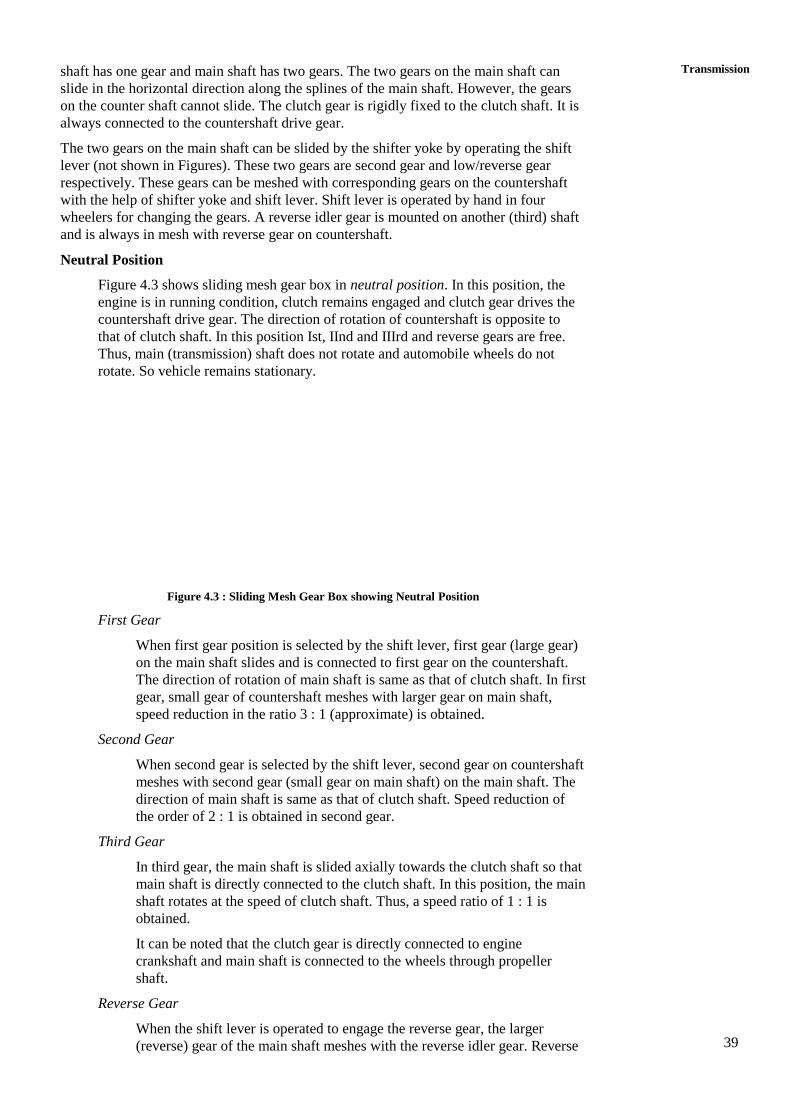
Neutral Position
Figure 4.3 shows sliding mesh gear box in neutral position. In this position, the
engine is in running condition, clutch remains engaged and clutch gear drives the
countershaft drive gear. The direction of rotation of countershaft is opposite to
that of clutch shaft. In this position Ist, IInd and IIIrd and reverse gears are free.
Thus, main (transmission) shaft does not rotate and automobile wheels do not
rotate. So vehicle remains stationary.
Figure 4.3 : Sliding Mesh Gear Box showing Neutral Position
First Gear
When first gear position is selected by the shift lever, first gear (large gear)
on the main shaft slides and is connected to first gear on the countershaft.
The direction of rotation of main shaft is same as that of clutch shaft. In first
gear, small gear of countershaft meshes with larger gear on main shaft,
speed reduction in the ratio 3 : 1 (approximate) is obtained.
Second Gear
When second gear is selected by the shift lever, second gear on countershaft
meshes with second gear (small gear on main shaft) on the main shaft. The
direction of main shaft is same as that of clutch shaft. Speed reduction of
the order of 2 : 1 is obtained in second gear.
Third Gear
In third gear, the main shaft is slided axially towards the clutch shaft so that
main shaft is directly connected to the clutch shaft. In this position, the main
shaft rotates at the speed of clutch shaft. Thus, a speed ratio of 1 : 1 is
obtained.
It can be noted that the clutch gear is directly connected to engine
crankshaft and main shaft is connected to the wheels through propeller
shaft.
Reverse Gear
When the shift lever is operated to engage the reverse gear, the larger
(reverse) gear of the main shaft meshes with the reverse idler gear. Reverse
40
Automobile Engineering
idler gear is always connected to reverse gear on countershaft. The reverse
idler gear between countershaft reverse gear and main shaft larger gear
changes the direction of rotation of main shaft. Thus, the direction of main
shaft becomes opposite to that of clutch shaft. Therefore, wheels of the
automobile start moving in backward direction.
(Note : Countershaft is also known as lay shaft.)
In modern cars, there are five forward gears and reverse gear. Hence, they
provide five speed ratios for forward racing and one for backward
movement.
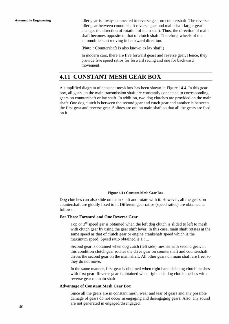
4.11 CONSTANT MESH GEAR BOX
A simplified diagram of constant mesh box has been shown in Figure 14.4. In this gear
box, all gears on the main transmission shaft are constantly connected to corresponding
gears on countershaft or lay shaft. In addition, two dog clutches are provided on the main
shaft. One dog clutch is between the second gear and cutch gear and another is between
the first gear and reverse gear. Splines are out on main shaft so that all the gears are feed
on it.
Figure 4.4 : Constant Mesh Gear Box
Dog clutches can also slide on main shaft and rotate with it. However, all the gears on
countershaft are giddily fixed to it. Different gear ratios (speed ratios) are obtained as
follows :
For Three Forward and One Reverse Gear
Top or 3rd
speed gar is obtained when the left dog clutch is slided to left to mesh
with clutch gear by using the gear shift lever. In this case, main shaft rotates at the
same speed as that of clutch gear or engine crankshaft speed which is the
maximum speed. Speed ratio obtained is 1 : 1.
Second gear is obtained when dog cutch (left side) meshes with second gear. In
this condition clutch gear rotates the drive gear on countershaft and countershaft
drives the second gear on the main shaft. All other gears on main shaft are free, so
they do not move.
In the same manner, first gear is obtained when right hand side dog clutch meshes
with first gear. Reverse gear is obtained when right side dog clutch meshes with
reverse gear on main shaft.
Advantage of Constant Mesh Gear Box
Since all the gears are in constant mesh, wear and tear of gears and any possible
damage of gears do not occur in engaging and disengaging gears. Also, any sound
are not generated in engaged/disengaged.
41
Transmission SAQ 2
(a) What do you mean by transmission in an automobile? Describe its purpose.
(b) List different type of gear boxes used in automobiles. Explain the working
of constant mesh gear box with the help of a simple diagram.
(c) Write any three differences between a sliding mesh and constant mesh gear
box.
(d) Enumerate the advantages of a constant mesh gear box over sliding mesh
gear box.
(e) How do you obtain reverse gear in a sliding mesh gear box?
4.12 GEAR TRAINS
A combination of two or more gears, which mesh in such a way that power is transmitted
from driving shaft to driven shaft, is known as gear train.
4.13 TYPES OF GEAR TRAINS
There are three types of gear trains :
(a) Simple gear train,
(b) Compound gear train, and
(c) Epicyclic gear train.
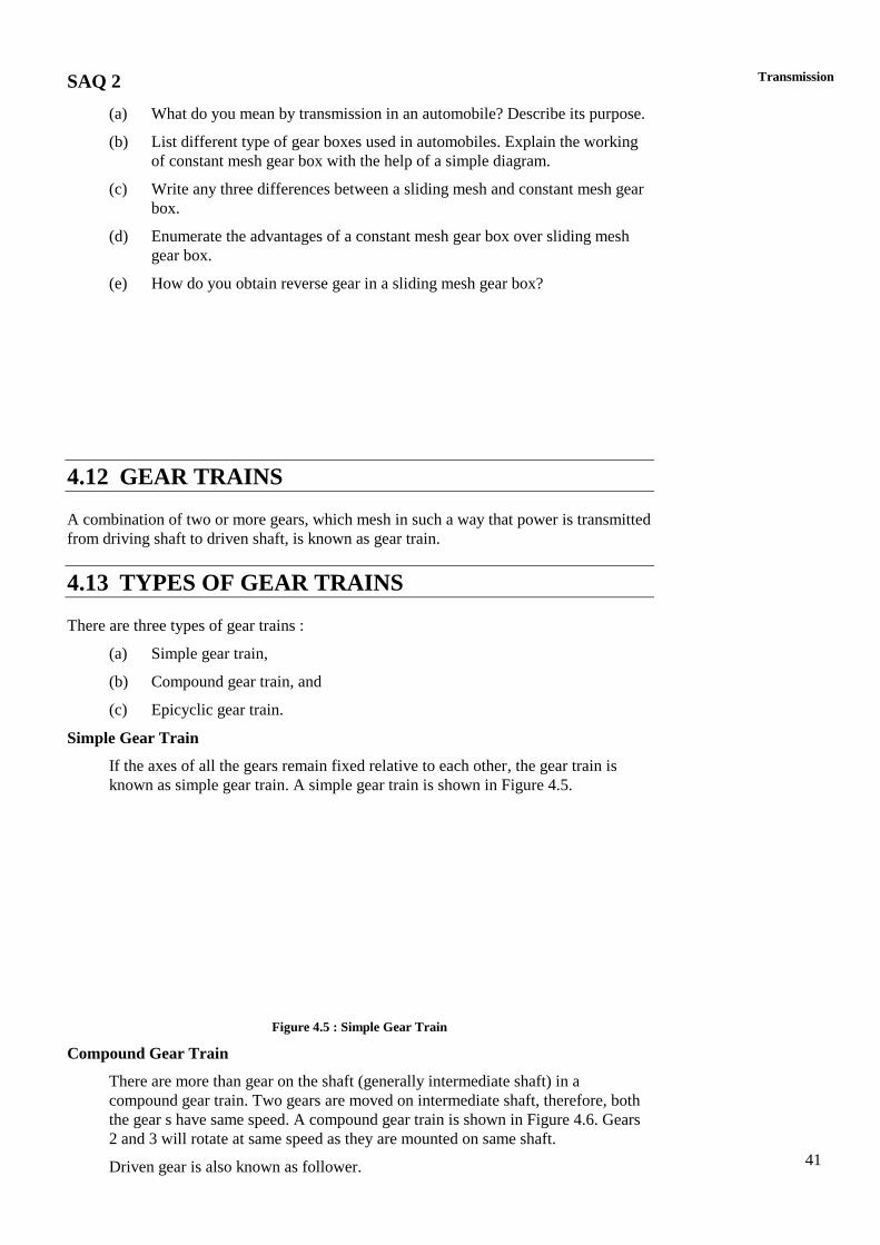
Simple Gear Train
If the axes of all the gears remain fixed relative to each other, the gear train is
known as simple gear train. A simple gear train is shown in Figure 4.5.
Figure 4.5 : Simple Gear Train
Compound Gear Train
There are more than gear on the shaft (generally intermediate shaft) in a
compound gear train. Two gears are moved on intermediate shaft, therefore, both
the gear s have same speed. A compound gear train is shown in Figure 4.6. Gears
2 and 3 will rotate at same speed as they are mounted on same shaft.
Driven gear is also known as follower.
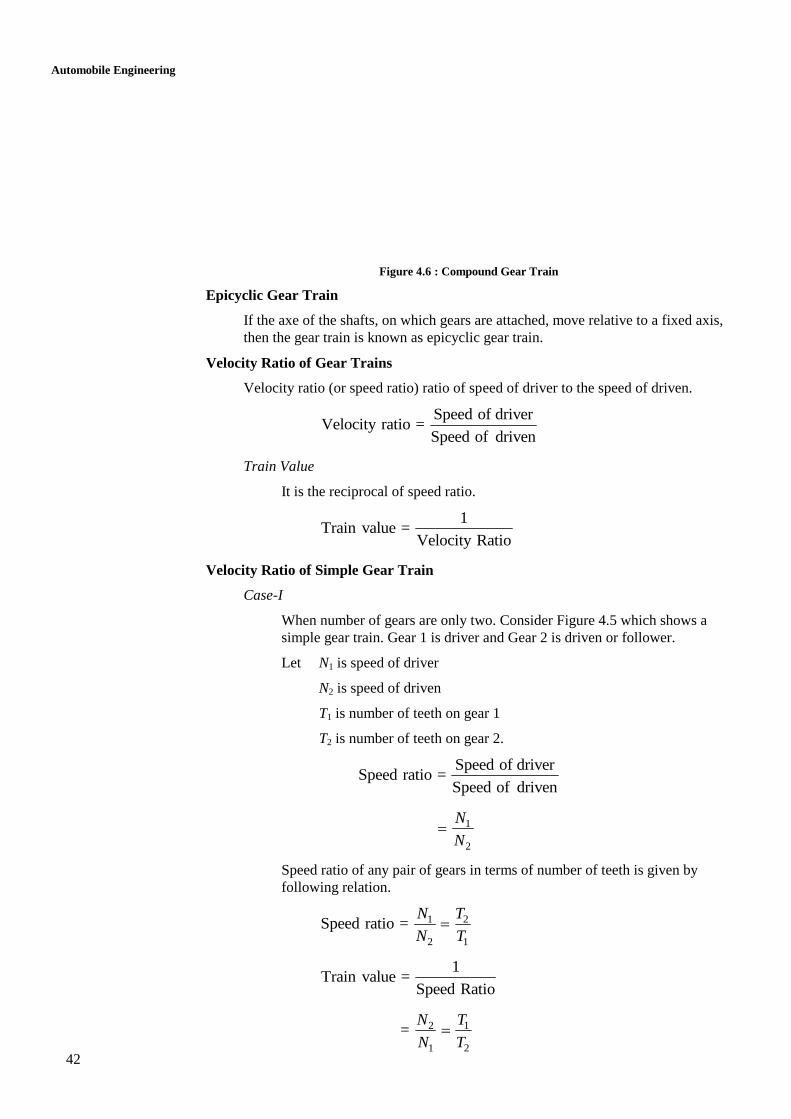
42
Automobile Engineering
Figure 4.6 : Compound Gear Train
Epicyclic Gear Train
If the axe of the shafts, on which gears are attached, move relative to a fixed axis,
then the gear train is known as epicyclic gear train.
Velocity Ratio of Gear Trains
Velocity ratio (or speed ratio) ratio of speed of driver to the speed of driven.
Speed of driver
Velocity ratio =Speed of driven
Train Value
It is the reciprocal of speed ratio.
1
Train value =Velocity Ratio
Velocity Ratio of Simple Gear Train
Case-I
When number of gears are only two. Consider Figure 4.5 which shows a
simple gear train. Gear 1 is driver and Gear 2 is driven or follower.
Let N1 is speed of driver
N2 is speed of driven
T1 is number of teeth on gear 1
T2 is number of teeth on gear 2.
Speed of driver
Speed ratio =Speed of driven
1
2
N
N
Speed ratio of any pair of gears in terms of number of teeth is given by
following relation.
1 2
2 1
Speed ratio = N T
N T
1
Train value =Speed Ratio
2 1
1 2
= N T
N T
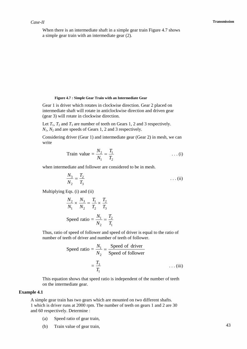
43
Transmission Case-II
When there is an intermediate shaft in a simple gear train Figure 4.7 shows
a simple gear train with an intermediate gear (2).
Figure 4.7 : Simple Gear Train with an Intermediate Gear
Gear 1 is driver which rotates in clockwise direction. Gear 2 placed on
intermediate shaft will rotate in anticlockwise direction and driven gear
(gear 3) will rotate in clockwise direction.
Let T1, T2 and T3 are number of teeth on Gears 1, 2 and 3 respectively.
N1, N2 and are speeds of Gears 1, 2 and 3 respectively.
Considering driver (Gear 1) and intermediate gear (Gear 2) in mesh, we can
write
2 1
1 2
Train value = N T
N T . . . (i)
when intermediate and follower are considered to be in mesh.
3 2
2 3
N T
N T . . . (ii)
Multiplying Eqs. (i) and (ii)
32 1 2
1 2 2 3
NN T T
N N T T
1 2
2 1
Speed ratio = N T
N T
Thus, ratio of speed of follower and speed of driver is equal to the ratio of
number of teeth of driver and number of teeth of follower.
1
2
Speed of driverSpeed ratio =
Speed of follower
N
N
3
1
=T
T . . . (iii)
This equation shows that speed ratio is independent of the number of teeth
on the intermediate gear.
Example 4.1
A simple gear train has two gears which are mounted on two different shafts.
1 which is driver runs at 2000 rpm. The number of teeth on gears 1 and 2 are 30
and 60 respectively. Determine :
(a) Speed ratio of gear train,
(b) Train value of gear train,
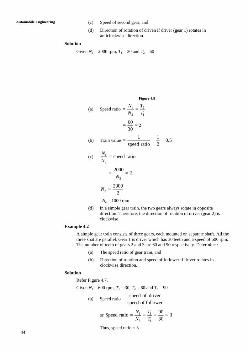
44
Automobile Engineering
(c) Speed of second gear, and
(d) Direction of rotation of driven if driver (gear 1) rotates in
anticlockwise direction.
Solution
Given N1 = 2000 rpm, T1 = 30 and T2 = 60
Figure 4.8
(a) Speed ratio 1 2
2 1
= N T
N T
60
=30
= 2
(b) Train value 1 1
= 0.5speed ratio 2
(c) 1
2
= speed ratioN
N
2
2000= 2
N
2
2000
2N
N2 = 1000 rpm
(d) In a simple gear train, the two gears always rotate in opposite
direction. Therefore, the direction of rotation of driver (gear 2) is
clockwise.
Example 4.2
A simple gear train consists of three gears, each mounted on separate shaft. All the
three shat are parallel. Gear 1 is driver which has 30 teeth and a speed of 600 rpm.
The number of teeth of gears 2 and 3 are 60 and 90 respectively. Determine :
(a) The speed ratio of gear train, and
(b) Direction of rotation and speed of follower if driver rotates in
clockwise direction.
Solution
Refer Figure 4.7.
Given N1 = 600 rpm, T1 = 30, T2 = 60 and T3 = 90
(a) Speed ratio speed of driver
=speed of follower
or 31
3 1
90Speed ratio = 3
30
TN
N T
Thus, speed ratio = 3.
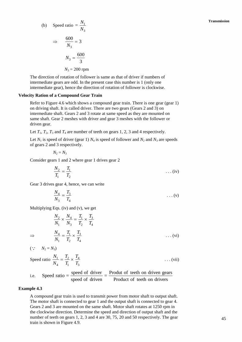
45
Transmission
(b) Speed ratio 1
3
=N
N
3
6003
N
3
600
3N
N3 = 200 rpm
The direction of rotation of follower is same as that of driver if numbers of
intermediate gears are odd. In the present case this number is 1 (only one
intermediate gear), hence the direction of rotation of follower is clockwise.
Velocity Ration of a Compound Gear Train
Refer to Figure 4.6 which shows a compound gear train. There is one gear (gear 1)
on driving shaft. It is called driver. There are two gears (Gears 2 and 3) on
intermediate shaft. Gears 2 and 3 rotate at same speed as they are mounted on
same shaft. Gear 2 meshes with driver and gear 3 meshes with the follower or
driven gear.
Let T1, T2, T3 and T4 are number of teeth on gears 1, 2, 3 and 4 respectively.
Let N1 is speed of driver (gear 1) N4 is speed of follower and N2 and N3 are speeds
of gears 2 and 3 respectively.
N2 = N3
Consider gears 1 and 2 where gear 1 drives gear 2
2 1
1 2
N T
T T . . . (iv)
Gear 3 drives gear 4, hence, we can write
34
3 4
TN
N T . . . (v)
Multiplying Eqs. (iv) and (v), we get
32 4 1
1 3 2 4
TN N T
N N T T
34 1
1 2 4
TN T
N T T . . . (vi)
( N2 = N3)
Speed ratio 1 2 4
4 1 3
N T T
N T T . . . (vii)
i.e. speed of driver Produt of teeth on driven gears
Speed ratio = =speed of driven Product of teeth on drivers
Example 4.3
A compound gear train is used to transmit power from motor shaft to output shaft.
The motor shaft is connected to gear 1 and the output shaft is connected to gear 4.
Gears 2 and 3 are mounted on the same shaft. Motor shaft rotates at 1250 rpm in
the clockwise direction. Determine the speed and direction of output shaft and the
number of teeth on gears 1, 2, 3 and 4 are 30, 75, 20 and 50 respectively. The gear
train is shown in Figure 4.9.
46
Automobile Engineering
Figure 4.9 : Compound Gear Train
Solution
Given T1 = 30, T2 = 75, T3 = 29 and T4 = 50
N1 = 1250 rpm
From Figure 4.9, it is evident that gears 1 and 3 are driving gears and gears 2 and 4
are driven gears or followers. Since, gears 2 and 3 are mounted on same shaft,
N2 = N3 and their direction of rotation will be same.
Let N4 is the speed of output shaft. It is same as the speed of gear 4.
Using formula :
Speed of first driver Produt of no. of teeth on followers
=speed of last follower Product of no. of teeth on drivers
i.e. 1 2 4
4 1 3
N T T
N T T
4
1250 75 50
30 20
N
or 4
12506.25
N
4
1250
6.25N
N4 = 200 rpm
Directional of Rotation of Output Shaft (or Gear 4)
The gear 1 rotates in clockwise direction. So, gear 2 will rotate in anticlockwise
direction because it is in mesh with gear 1. Gear 3 is on the same shaft as gear 2,
so it will also rotate in anticlockwise direction. Since, gear 4 is in mesh with gear
3, it will rotate in opposite direction, i.e. in clockwise direction.
Hence, direction of rotation of output shaft is clockwise.
SAQ 1
(a) What do you mean by gear train? List different types of gear trains.
(b) Differentiate between simple gear train and compound gear train.
(c) What do you mean by train value? How is it related to velocity ratio?
(d) Define the term, velocity ratio. What is the formula for calculating the
velocity ratio of simple gear train and compound gear train.
(e) What is epicyclic gear train?
47
Transmission SAQ 2
(a) A simple gear train consists of two gears which are mounted on two
different shafts. The two shafts are parallel. Gear 1 is driver and gear 2 is
follower. The speed of gear 1 is 600 rpm. The number of teeth on gears 1
and 2 are 20 and 60 respectively. Determine :
(i) Speed or velocity ratio of gear train,
(ii) Train value,
(ii) Speed of second gear, and
(iv) Direction of rotation of second gear if first gear rotates in clockwise
direction.
(b) A simple gear train consists of three gears each of which mounted on a
separate shaft. All the three shafts are parallel. Gear 1 is driver and rotates
at 1000 rpm. Gear 1 drives gear 2 and gear 2 drives gear 3. The number of
teeth on gears 1, 2 and 3 are 20, 30 and 50 respectively. Find :
(i) Speed ration of gear train,
(ii) Speed of follower (i.e. gear 3), and
(iii) Direction of rotation of follower if gear 1 rotates in clockwise
direction.
(c) Refer to Figure 4.9 which shows a compound gear train. It is used to
transmit power from motor shaft to output shaft. The gear 1 is mounted on
motor shaft, gears 2 and 3 are mounted on intermediate shaft, and gear 4 is
mounted on output shaft. Gear 1 drives gear 2 and gear 3 drives gear 4.
Motor shaft rotates at 1200 rpm in clockwise direction. Number of teeth on
gears 1, 2, 3 and 4 are 25, 50, 30 and 60 respectively. Determine :
(i) Speed ratio,
(ii) Direction and speed of the follower, and
(iii) Train value.
4.13 SUMMARY
Every student, who is studying the course automobile engineering, must have the
knowledge of transmission system of an automobile. Transmission system is nothing but
transmitting the power from engine to the wheels transfer clutch and gear mechanisms.
So, in this unit, we have studied about the transmission system of automobile. The
transmission system mainly comprises of clutch and gear mechanisms. We have learnt
about the functions and types of clutches and gear boxes. Clutch is mainly used to
yougase or disagause the engine to the transmission or gear box. Gear box is used to
varying the speeds of automobile according to the required conditions or according to the
need of the persons, who are driving the automobile.
48
Automobile Engineering
4.14 KEY WORDS
4.15 ANSWERS TO SAQs
Refer the preceding text for all the Answers to SAQs.
49
Final Drive
UNIT 5 FINAL DRIVE
Structure
5.1 Introduction
Objectives
5.2 Universal Joints
5.3 Types of Universal Joints
5.4 Propeller Shaft
5.5 Final Drive or Final Reduction
5.6 Differential
5.7 Types of Differential
5.8 Rear Axles
5.9 Types of Rear Axles
5.10 Summary
5.11 Key Words
5.12 Answers to SAQs
5.1 INTRODUCTION
The power developed by the engine is transferred to the wheels through clutch, gear box,
universal joints, propeller shaft, final drive, differential and rear axles. Description of
universal joints, propeller shaft, final drive, differential and rear axles has been given in
this unit.
Objectives
After studying this unit, you should be able to
,
,
, and
.
5.2 UNIVERSAL JOINTS
Universal joint is used to connect two shafts at an angle for transmitting torque. In the
transmission shaft of an automobile, two universal joints are used – one between main
transmission shaft and propeller shaft and another between other end of propeller shaft
and the differential. Therefore, the universal joints make the joints flexible so that power
can be transmitted at an angle.
A universal joint takes care of rising and falling motion of the rear end of the propeller
shaft which is connected to differential. Two universal joints are shown in Figure 5.1
along with the propeller shaft.
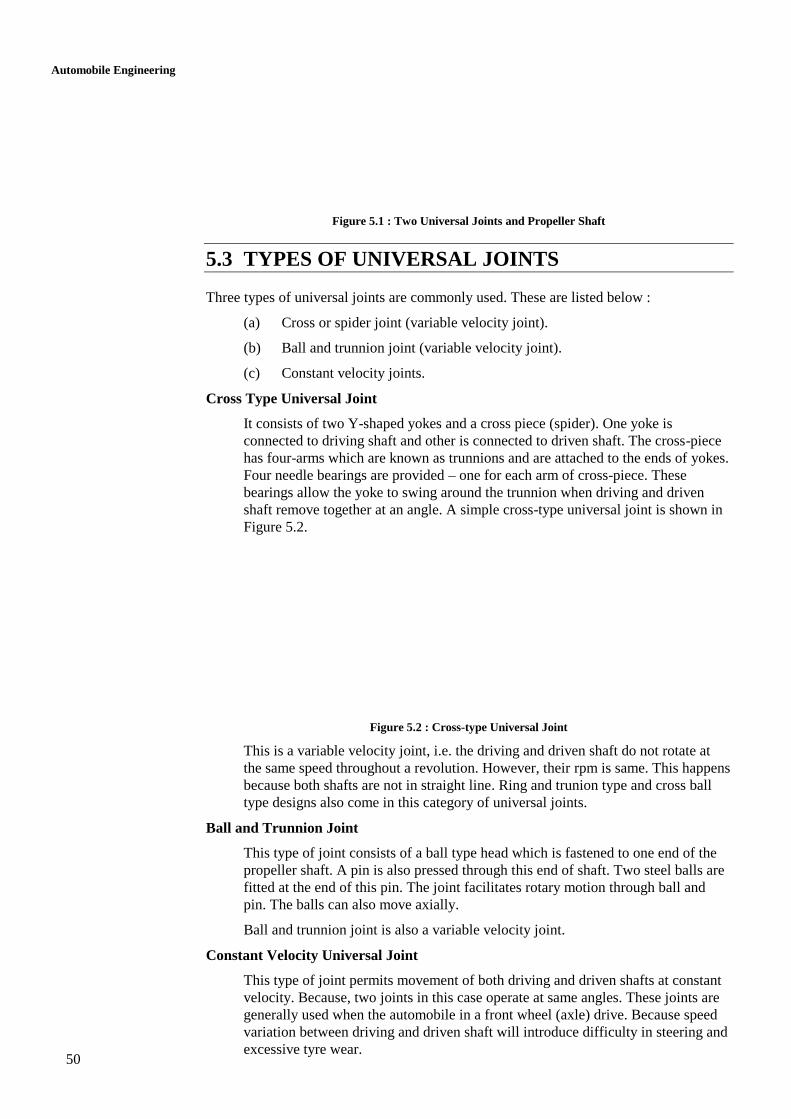
50
Automobile Engineering
Figure 5.1 : Two Universal Joints and Propeller Shaft
5.3 TYPES OF UNIVERSAL JOINTS
Three types of universal joints are commonly used. These are listed below :
(a) Cross or spider joint (variable velocity joint).
(b) Ball and trunnion joint (variable velocity joint).
(c) Constant velocity joints.
Cross Type Universal Joint
It consists of two Y-shaped yokes and a cross piece (spider). One yoke is
connected to driving shaft and other is connected to driven shaft. The cross-piece
has four-arms which are known as trunnions and are attached to the ends of yokes.
Four needle bearings are provided – one for each arm of cross-piece. These
bearings allow the yoke to swing around the trunnion when driving and driven
shaft remove together at an angle. A simple cross-type universal joint is shown in
Figure 5.2.
Figure 5.2 : Cross-type Universal Joint
This is a variable velocity joint, i.e. the driving and driven shaft do not rotate at
the same speed throughout a revolution. However, their rpm is same. This happens
because both shafts are not in straight line. Ring and trunion type and cross ball
type designs also come in this category of universal joints.
Ball and Trunnion Joint
This type of joint consists of a ball type head which is fastened to one end of the
propeller shaft. A pin is also pressed through this end of shaft. Two steel balls are
fitted at the end of this pin. The joint facilitates rotary motion through ball and
pin. The balls can also move axially.
Ball and trunnion joint is also a variable velocity joint.
Constant Velocity Universal Joint
This type of joint permits movement of both driving and driven shafts at constant
velocity. Because, two joints in this case operate at same angles. These joints are
generally used when the automobile in a front wheel (axle) drive. Because speed
variation between driving and driven shaft will introduce difficulty in steering and
excessive tyre wear.
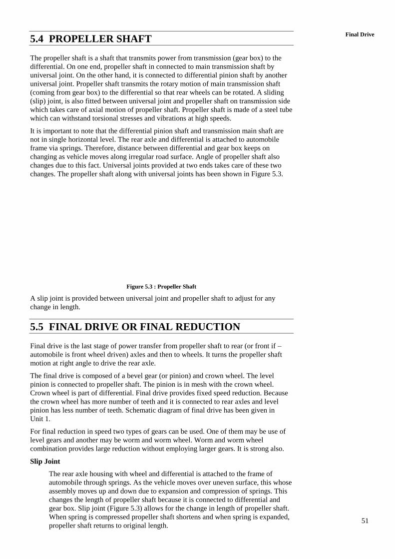
51
Final Drive 5.4 PROPELLER SHAFT
The propeller shaft is a shaft that transmits power from transmission (gear box) to the
differential. On one end, propeller shaft in connected to main transmission shaft by
universal joint. On the other hand, it is connected to differential pinion shaft by another
universal joint. Propeller shaft transmits the rotary motion of main transmission shaft
(coming from gear box) to the differential so that rear wheels can be rotated. A sliding
(slip) joint, is also fitted between universal joint and propeller shaft on transmission side
which takes care of axial motion of propeller shaft. Propeller shaft is made of a steel tube
which can withstand torsional stresses and vibrations at high speeds.
It is important to note that the differential pinion shaft and transmission main shaft are
not in single horizontal level. The rear axle and differential is attached to automobile
frame via springs. Therefore, distance between differential and gear box keeps on
changing as vehicle moves along irregular road surface. Angle of propeller shaft also
changes due to this fact. Universal joints provided at two ends takes care of these two
changes. The propeller shaft along with universal joints has been shown in Figure 5.3.
Figure 5.3 : Propeller Shaft
A slip joint is provided between universal joint and propeller shaft to adjust for any
change in length.
5.5 FINAL DRIVE OR FINAL REDUCTION
Final drive is the last stage of power transfer from propeller shaft to rear (or front if –
automobile is front wheel driven) axles and then to wheels. It turns the propeller shaft
motion at right angle to drive the rear axle.
The final drive is composed of a bevel gear (or pinion) and crown wheel. The level
pinion is connected to propeller shaft. The pinion is in mesh with the crown wheel.
Crown wheel is part of differential. Final drive provides fixed speed reduction. Because
the crown wheel has more number of teeth and it is connected to rear axles and level
pinion has less number of teeth. Schematic diagram of final drive has been given in
Unit 1.
For final reduction in speed two types of gears can be used. One of them may be use of
level gears and another may be worm and worm wheel. Worm and worm wheel
combination provides large reduction without employing larger gears. It is strong also.
Slip Joint
The rear axle housing with wheel and differential is attached to the frame of
automobile through springs. As the vehicle moves over uneven surface, this whose
assembly moves up and down due to expansion and compression of springs. This
changes the length of propeller shaft because it is connected to differential and
gear box. Slip joint (Figure 5.3) allows for the change in length of propeller shaft.
When spring is compressed propeller shaft shortens and when spring is expanded,
propeller shaft returns to original length.
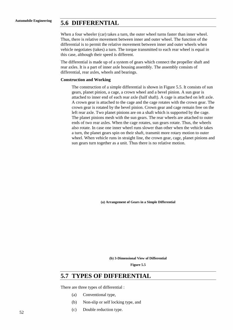
52
Automobile Engineering
5.6 DIFFERENTIAL
When a four wheeler (car) takes a turn, the outer wheel turns faster than inner wheel.
Thus, there is relative movement between inner and outer wheel. The function of the
differential is to permit the relative movement between inner and outer wheels when
vehicle negotiates (takes) a turn. The torque transmitted to each rear wheel is equal in
this case, although their speed is different.
The differential is made up of a system of gears which connect the propeller shaft and
rear axles. It is a part of inner axle housing assembly. The assembly consists of
differential, rear axles, wheels and bearings.
Construction and Working
The construction of a simple differential is shown in Figure 5.5. It consists of sun
gears, planet pinion, a cage, a crown wheel and a bevel pinion. A sun gear is
attached to inner end of each rear axle (half shaft). A cage is attached on left axle.
A crown gear is attached to the cage and the cage rotates with the crown gear. The
crown gear is rotated by the bevel pinion. Crown gear and cage remain free on the
left rear axle. Two planet pinions are on a shaft which is supported by the cage.
The planet pinions mesh with the sun gears. The rear wheels are attached to outer
ends of two rear axles. When the cage rotates, sun gears rotate. Thus, the wheels
also rotate. In case one inner wheel runs slower than other when the vehicle takes
a turn, the planet gears spin on their shaft, transmit more rotary motion to outer
wheel. When vehicle runs in straight line, the crown gear, cage, planet pinions and
sun gears turn together as a unit. Thus there is no relative motion.
(a) Arrangement of Gears in a Simple Differential
(b) 3-Dimensional View of Differential
Figure 5.5
5.7 TYPES OF DIFFERENTIAL
There are three types of differential :
(a) Conventional type,
(b) Non-slip or self locking type, and
(c) Double reduction type.
53
Final Drive Conventional Type
Conventional type differential described in Section 5.6 delivers same torque to
each rear wheel. If any of the wheels slips due to any reason the wheel does not
rotate and vehicle does not move.
Non-slip or Self Locking Type
Non-slip or self locking type differential overcomes this drawback. It construction
is similar to that of conventional type differential. But, two sets of clutch plates
are provided additionally. Also, the ends of planet shafts are left loose in notches
provided on the differential cage.
Double Reduction Type
Double reduction type differential provides further speed reduction by additional
gear. This type of differential is used in heavy duty automobiles which require
larger gear reduction between engine and wheels.
5.8 REAR AXLES
Rear axle transmits power from differential to the wheels so that vehicle may move. Rear
axle is not a single piece but it is in two parts which are connected by the differential.
This is shown in Figure 5.5. Each part of rear axle is called the half shaft. Outer end of
the rear axle carries the wheel while inner end is connected to sun gear of the
differential. In vehicles which employ rear wheel drive, rear wheels are driving wheels.
However, in front wheel drive vehicles, front wheels are driving wheels. Rear axles and
differential are completely enclosed in a housing to protect them from dust, dirt, water
and any possible damage.
Functions of Rear Axle
(a) To transmit power from differential to the wheels. This is main function.
(b) To carry weight of automobile.
5.9 TYPES OF REAR AXLES
Rear axles differ on the basis of method of supporting them and mounting of rear
wheels. On this basis, these axles can be classified into three types :
(a) Half floating axle shown in Figure 5.6.
(b) Three-quarter floating axle shown in Figure 5.7.
(c) Fully floating rear axle shown in Figure 5.8.
Half Floating Axle
In a half floating rear axle, the axle is at the centre of the axle casing and the
bearings are inside the axle casing. The weight of vehicle is transmitted first to
suspension spring, then to axle casing, then to axle and finally to ground.
Figure 5.6 : Half Floating Rear Axle
54
Automobile Engineering
Three-quarter Floating Axle
In three-quarter floating rear axle, bearings are on the outer side of axle casing, i.e.
between casing and wheel. In this case, major part of vehicle weight is taken by
axle casing and not by axle. This is the main advantage of three-quarter floating
type over half floating type. Thus, axle breakdown is less in this case compared to
the previous type.
Figure 5.7 : Three-quarter Floating Rear Axle
Fully Floating Rear Axle
In fully floating rear axle, the bearings are provided between axle casing and the
wheel. In this case, all the vehicle weight is transmitted to ground through axle
case and wheel. The axle is not supported by bearings but it is supported at both
ends. This type of axle is very strong and therefore, it is used for heavy duty
vehicles. In the event of breakdown of axle, wheel cannot come out. This, it is
safer but costly.
Figure 5.8 : Full Floating Rear Axle
SAQ 1
(a) What is the function of an universal joint? Where it is used in the
transmission system of an automobile?
(b) List different types of universal joints and describe the construction and
features of cross type joint.
(c) What is the function of propeller shaft? How it is connected in the
transmission system?
(d) Why is slip joint used with the propeller shaft?
(e) Write the function of final drive.

55
Final Drive SAQ 2
(a) What is the purpose of using a differential in an automobile?
(b) Describe the working of differential.
(c) Why rear axle is in two halves?
(d) List various type of rear axles and describe the working of half or
semi-floating rear axle.
(e) Which type of rear axle is used for heavy duty (load) vehicle?
5.10 SUMMARY
5.11 KEY WORDS
5.12 ANSWERS TO SAQs
Refer the preceding text for all the Answers to SAQs.
57
Braking System
UNIT 6 BRAKING SYSTEM
Structure
6.1 Introduction
Objectives
6.2 Functions of Brakes
6.3 Principle of Vehicle Braking
6.4 Classification of Brakes
6.5 Short Notes on Miscellaneous Braking Systems
6.5.1 Air Brakes
6.5.2 Vacuum Brakes
6.5.3 Electric Brakes
6.6 Hydraulic Brakes
6.7 Advantages and Disadvantages of Hydraulic Brakes
6.8 Construction and Working of Mechanical Brakes
6.9 Disc Brakes
6.10 Parking Brake or Emergency Brake
6.11 Bleeding of Brakes
6.12 Adjustment of Brakes
6.13 Summary
6.14 Key Words
6.15 Answers to SAQs
6.1 INTRODUCTION
Baking system is necessary in an automobile for stopping the vehicle. Brakes are applied
on the wheels to stop or to slow down the vehicle.
Objectives
After studying this unit, you should be able to
,
,
, and
.
6.2 FUNCTIONS OF VEHICLE BRAKING
There are two main functions of brakes :
(a) To slow down or stop the vehicle in the shortest possible time at the time of
need.
(b) To control the speed of vehicle at turns and also at the time of driving down
on a hill slope.
58
Automobile Engineering
6.3 PRINCIPLE OF VEHICLE BRAKING
Braking of a vehicle depends upon the static function that acts between tyres and road
surface. Brakes work on the following principle to stop the vehicle :
“The kinetic energy due to motion of the vehicle is dissipated in the form of heat energy
due to friction between moving parts (wheel or wheel drum) and stationary parts of
vehicle (brake shoes)”.
The heat energy so generate4d due to application of brakes is dissipated into air.
Brakes operate most effectively when they are applied in a manner so that wheels do not
lock completely but continue to roll without slipping on the surface of road.
6.4 CLASSIFICATION OF BRAKES
On the Basis of Method of Actuation
(a) Foot brake (also called service brake) operated by foot pedal.
(b) Hand brake – it is also called parking brake operated by hand.
On the Basis of Mode of Operation
(a) Mechanical brakes
(b) Hydraulic brakes
(c) Air brakes
(d) Vacuum brakes
(e) Electric brakes.
On the Basis of Action on Front or Rear Wheels
(a) Front-wheel brakes
(b) Rear-wheel brakes.
On the Basis of Method of Application of Braking Contact
(a) Internally – expanding brakes
(b) Externally – contracting brakes.
6.5 SHORT NOTES ON MISCELLANEOUS
BRAING SYSTEMS
6.5.1 Air Brakes
Air brakes are applied by the pressure of compressed air. Air pressure applies force on
brakes shoes through suitable linkages to operate brakes. An air compressor is used to
compress air. This compressor is run by engine power.
6.5.2 Vacuum Brakes
Vacuum brakes are a piston or a diaphragm operating in a cylinder. For application of
brakes one side of piston is subjected to atmospheric pressure while the other is applied
vacuum by exhausting air from this side. A force acts on the piston due to difference of
pressure. This force is used to operate brake through suitable linkages.
6.4.3 Electric Brakes
In electrical brakes an electromagnet is used to actuate a cam to expand the brake shoes.
The electromagnet is energized by the current flowing from the battery. When flow of
current is stopped the cam and brake shoes return to their original position and brakes
are disengaged. Electric brakes are not used in automobiles as service brakes.
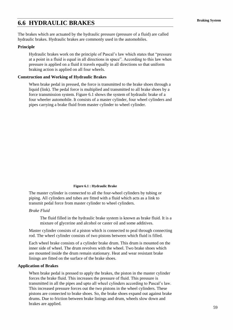
59
Braking System 6.6 HYDRAULIC BRAKES
The brakes which are actuated by the hydraulic pressure (pressure of a fluid) are called
hydraulic brakes. Hydraulic brakes are commonly used in the automobiles.
Principle
Hydraulic brakes work on the principle of Pascal’s law which states that “pressure
at a point in a fluid is equal in all directions in space”. According to this law when
pressure is applied on a fluid it travels equally in all directions so that uniform
braking action is applied on all four wheels.
Construction and Working of Hydraulic Brakes
When brake pedal in pressed, the force is transmitted to the brake shoes through a
liquid (link). The pedal force is multiplied and transmitted to all brake shoes by a
force transmission system. Figure 6.1 shows the system of hydraulic brake of a
four wheeler automobile. It consists of a master cylinder, four wheel cylinders and
pipes carrying a brake fluid from master cylinder to wheel cylinder.
Figure 6.1 : Hydraulic Brake
The master cylinder is connected to all the four-wheel cylinders by tubing or
piping. All cylinders and tubes are fitted with a fluid which acts as a link to
transmit pedal force from master cylinder to wheel cylinders.
Brake Fluid
The fluid filled in the hydraulic brake system is known as brake fluid. It is a
mixture of glycerine and alcohol or caster oil and some additives.
Master cylinder consists of a piston which is connected to peal through connecting
rod. The wheel cylinder consists of two pistons between which fluid is filled.
Each wheel brake consists of a cylinder brake drum. This drum is mounted on the
inner side of wheel. The drum revolves with the wheel. Two brake shoes which
are mounted inside the drum remain stationary. Heat and wear resistant brake
linings are fitted on the surface of the brake shoes.
Application of Brakes
When brake pedal is pressed to apply the brakes, the piston in the master cylinder
forces the brake fluid. This increases the pressure of fluid. This pressure is
transmitted in all the pipes and upto all wheel cylinders according to Pascal’s law.
This increased pressure forces out the two pistons in the wheel cylinders. These
pistons are connected to brake shoes. So, the brake shoes expand out against brake
drums. Due to friction between brake linings and drum, wheels slow down and
brakes are applied.
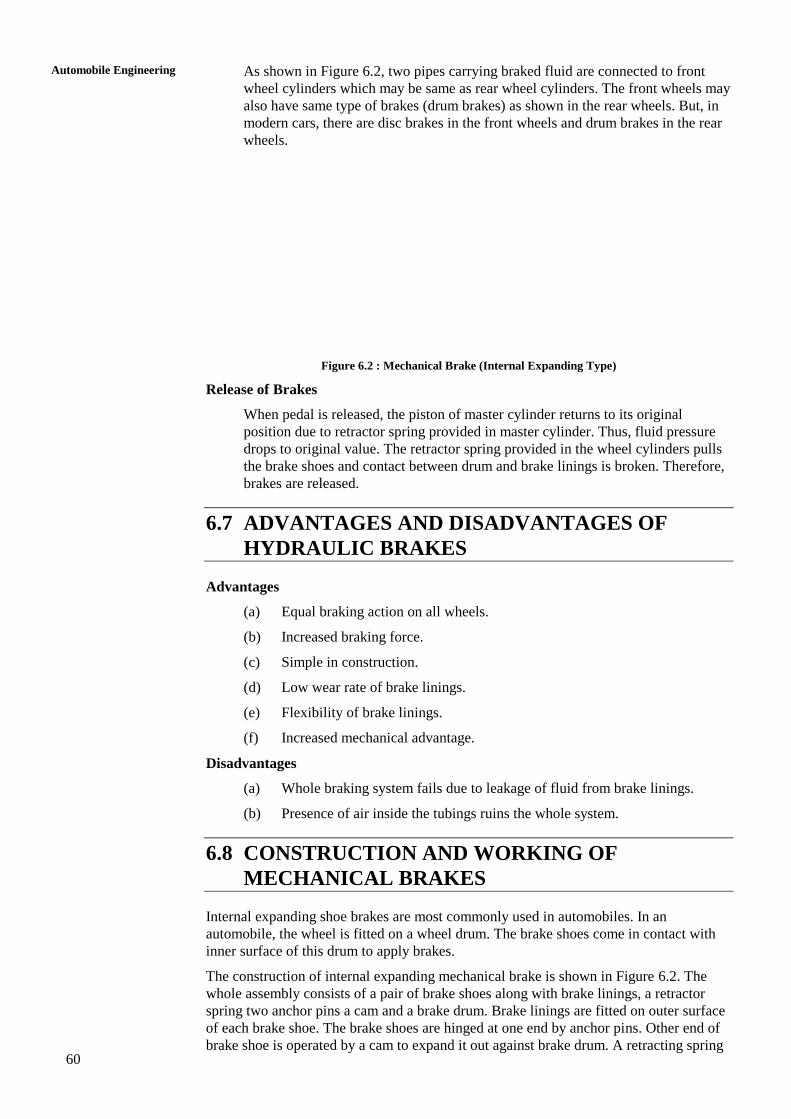
60
Automobile Engineering
As shown in Figure 6.2, two pipes carrying braked fluid are connected to front
wheel cylinders which may be same as rear wheel cylinders. The front wheels may
also have same type of brakes (drum brakes) as shown in the rear wheels. But, in
modern cars, there are disc brakes in the front wheels and drum brakes in the rear
wheels.
Figure 6.2 : Mechanical Brake (Internal Expanding Type)
Release of Brakes
When pedal is released, the piston of master cylinder returns to its original
position due to retractor spring provided in master cylinder. Thus, fluid pressure
drops to original value. The retractor spring provided in the wheel cylinders pulls
the brake shoes and contact between drum and brake linings is broken. Therefore,
brakes are released.
6.7 ADVANTAGES AND DISADVANTAGES OF
HYDRAULIC BRAKES
Advantages
(a) Equal braking action on all wheels.
(b) Increased braking force.
(c) Simple in construction.
(d) Low wear rate of brake linings.
(e) Flexibility of brake linings.
(f) Increased mechanical advantage.
Disadvantages
(a) Whole braking system fails due to leakage of fluid from brake linings.
(b) Presence of air inside the tubings ruins the whole system.
6.8 CONSTRUCTION AND WORKING OF
MECHANICAL BRAKES
Internal expanding shoe brakes are most commonly used in automobiles. In an
automobile, the wheel is fitted on a wheel drum. The brake shoes come in contact with
inner surface of this drum to apply brakes.
The construction of internal expanding mechanical brake is shown in Figure 6.2. The
whole assembly consists of a pair of brake shoes along with brake linings, a retractor
spring two anchor pins a cam and a brake drum. Brake linings are fitted on outer surface
of each brake shoe. The brake shoes are hinged at one end by anchor pins. Other end of
brake shoe is operated by a cam to expand it out against brake drum. A retracting spring

61
Braking System brings back shoes in their original position when brakes are not applied. The brake drum
closes inside it the whole mechanism to protect it from dust and first. A plate holds
whole assembly and fits to car axle. It acts as a base to fasten the brake shoes and other
operating mechanism.
How Brakes are Applied and Released
When brake pedal is pressed, the cam turns through brake linkages. Brake shoes
expand towards brake drum due to turning of cam. The brake linings, rub against
brake drum and therefore motion of wheels is stopped. The pedal force is
transmitted to the brake shoes through a mechanical linage. This mechanism also
multiplies the force to apply the brakes effectively.
When force on brake pedal is removed, the retractor spring brings back shoes in
original position and brakes are released.
6.9 DISC BRAKES
Modern motor cars are fitted with disc brakes instead of conventional drum type brakes.
In Santro car and Maruti-800, front wheels are provided with disc brakes whereas rear
wheel are provided with drum brakes. A disc brake consists of a rotating disc and two
friction pads which are actuated by hydraulic braking system as described earlier. The
friction pads remain free on each side of disc when brakes are no applied. They rub
against disc when brakes are applied to stop the vehicle. These brakes are applied in the
same manner as that of hydraulic brakes. But mechanism of stopping vehicle is different
than that of drum brakes.
Advantage of Disc Brakes
(a) Main advantage of disc brakes is their resistance to wear as the discs remain
cool even after repeated brake applications.
(b) Brake pads are easily replaceable.
(c) The condition of brake pads can be checked without much dismantling of
brake system.
Disadvantage of Disc Brakes
(a) More force is needed be applied as the brakes are not self emerging.
(b) Pad wear is more.
(c) Hand brakes are not effective if disc brakes are used in rear wheels also.
(Hand brakes are better with mechanical brakes).
6.10 PARKIG BRAKE OR EMERGENCY BRAKE
Parking brakes or emergency brakes are essentially mechanical brakes operated by hand.
These are used to prevent the motion of vehicle when parked at a place or when parked
on slopes. In cars, these brakes are generally attached to rear wheels. In this type, a cable
connects the hand lever to the brake. Brakes are applied by pulling the lever and released
by pushing a button (provided on lever) and pressing the lever down.
6.11 BLEEDING OF BRAKES
When air enters, into the brake system and any brake line is disconnected, bleeding of
brakes has to be done. Since air is compressible so any presence of air inside brake
lining does not allow to transmit brake force to apply brakes. Therefore, the system must
be free from presence of air. Bleeding is the process of removal of air from the braking
system.
62
Automobile Engineering
Bleeding Procedure
Following steps are followed for bleeding of brakes :
(a) Remove all dirt from the master cylinder filler plug. Then fill the
master cylinder upto lower edge of the filler neck by removing the
filler plug.
(b) Clean all the bleeding connections provided on all wheel cylinders.
(c) After this bleeder hose and fixture is connected to that wheel cylinder
which has longest brake line. The other rend of bleeder hose is placed
in a glass jar, and submerge this end in the brake fluid.
(d) How bleeder valve is opened by half to three quarter turn.
(e) Then press the foot pedal and allow it to return back slowly.
(f) This pumping action must be continued till all the air along with
some brake fluid comes out through bleeding hose.
(g) After this bleeding operation is carried out on all wheel cylinders.
This completes the bleeding operation. At the end master cylinder is
filled with brake fluid to required level.
6.12 ADJUSTMENT OF BRAKES
When pedal is pressed to apply brake, there should be atleast 1/2 inch free pedal
movement before breaking action starts. This may vary from company to company.
The brakes are adjusted as per the above mentioned recommendation before they are
ready to use. This is done by following a definite procedure.
(a) List the wheels by screw jack.
(b) Loosen the lock nut for the forward brake shoe and keep it in this position.
(c) Turn the eccentric with other wrench towards the front of automobile till
the brake shoe touches the drum.
(d) Release the eccentric while turning the wheel with one hand, till wheel
turns freely.
(e) Hold the eccentric in this position and tighter the lock nut.
(f) Repeat the same operation to adjust other shoe, but turn the eccentric in the
backward direction of the vehicle.
(g) Above procedure is repeated for all the four wheels.
SAQ 1
(a) Write the functions of brakes in an automobile.
(b) Explain the construction and working of mechanical brakes.
(c) Describe in brief the construction and working of hydraulic brakes.
(d) Write the advantages and disadvantages of hydraulic brakes.
(e) Write short notes on :
(i) Vacuum brakes,
(ii) Electrical brakes, and
(iii) Air brakes.
63
Braking System SAQ 2
(a) What are the functions of parking or emergency brakes?
(b) What do you mean by bleeding and adjustment of brakes?
(c) Describe the procedure of bleeding of brakes.
(d) Describe the procedure of adjustment of brakes.
(e) Why disc brakes are better than drum type brakes?
6.13 SUMMARY
6.14 KEY WORDS
6.15 ANSWERS TO SAQs
Refer the preceding text for all the Answers to SAQs.
65
Front Axle and Steering
UNIT 7 FRONT AXLE AND STEERING
Structure
7.1 Introduction
Objectives
7.2 Front Axle
7.3 Types of Front Axle
7.4 Stub Axle
7.5 Steering
7.6 Ackerman’s Principle of Steering
7.7 Steering Geometry
7.8 Camber Angle
7.9 King Pin Inclination
7.10 Caster Angle
7.11 Toe-in and Toe-out
7.12 Steering Gear Box
7.13 Steering Linkages
7.14 Layout of a Steering System
7.15 Summary
7.16 Key Words
7.17 Answers to SAQs
7.1 INTRODUCTION
In any motor cars and other four and six wheeler vehicles, steering is main component.
Properly designed steering, works well and guides the vehicle to move in correct
direction. Mainly steering is linked to the front axel with gear train mechanism. On the
front axle, wheels are mounted, and with the help of steering wheel, the driver can turn
the vehicle in right, left or straight directions.
The function of steering mechanism is clearly explained in this unit. In this unit, we also
elaborated on the front axel and its types.
Principle of steering, steering geometry, steering gearbox and working of steering
systems have been clearly explained.
Objectives
After studying this unit, you should be able to
understand about front axel and steering,
define function of front axle and steering,
explain the principle of steering mechanism,
describe the linking mechanism of front axle and steering wheel, and
understand the steering geometry.
66
Automobile Engineering
7.2 FRONT AXLE
Front wheels of the vehicle are mounted on front axles. Functions of front axle are listed
below :
(a) It supports the weight of front part of the vehicle.
(b) It facilitates steering.
(c) It absorbs shocks which are transmitted due to road surface irregularities.
(d) It absorbs torque applied on it due to braking of vehicle.
Construction and Operation
Front axle is made of I-section in the middle portion and circular or elliptical
section at the ends. The special x-section of the axle makes it able to withstand
bending loads due to weight of the vehicle and torque applied due to braking. On
kind of front axle is shown in Figure 7.1 which consists of main beam, stub axle,
and swivel pin, etc. The wheels are mounted on stub axles.
Figure 7.1 : Front Axle
7.3 TYPES OF FRONT AXLES
There is two types of front axles :
(a) Dead front axle, and
(b) Line front axle.
Dead Front Axle
Dead axles are those axles, which donet rotate. These axles have sufficient rigidity
and strength to take the weight. The ends of front axle are suitably designed to
accommodate stub axles.
Line Front Axle
Line axles are used to transmit power from gear box to front wheels. Line front
axles although, front wheels. Line front axles although resemble rear axles but
they are different at the ends where wheels are mounted. Maruti-800 has line front
axle.
7.4 STUB AXLE
Stub axles are connected to the front axle by king pins. Front wheels are mounted on
stub axles arrangement for steering is connected to stub axles. Stub axle turns on kind
pins. King pins is fitted in the front axle beam eye and is located and locked there by a
taper cotter pin. Stub axles are of four types :
(a) Elliot
(b) Reversed elliot
67
Front Axle and Steering (c) Lamoine
(d) Reversed lamoine
All are differ from each other in the manner in which they are connected to the front
axle. Elliot type stub axle is shown in Figure 7.1.
7.5 STEERING
A good steering mechanism is must for a vehicle’s stability at the time of turning.
Steering of four wheeler is designed in a manner so that it will not permit lateral slip of
front wheels during steering. There must be true rolling of wheels at the time of steering.
The front wheels are mounted on front axles to allow their left and right swing for
steering the vehicle. Steering is done by providing a suitable gearing and linkage
between front wheels and steering wheel. A simplified diagram of a steering system has
been shown in the Figure 7.2.
Figure 7.2 : Simple Driving of a Steering System
7.6 ACKERMAN’S PRINCIPLE OF STEERING
Ackerman’s steering gear mechanism is based on Ackerman’s principle of steering. The
mechanism consists of a cross link BC connected to short axles AL and DM of front
wheels through short arms AB and CD. These form the bell crank levers LAB and MDC.
In case of straight motion of automobile the cross-link BC remains parallel to AD and
short links AB and CD both make angle from the horizontal axis of chasis.
(a) For Straight Motion
(b) For Right Turn
Figure 7.3 : Ackerman’s Steering Mechanism (Principle)
68
Automobile Engineering
Fundamental equation of steering is satisfied when the links AB and BC are
proportioned suitably and angle is selected suitably. The condition for correct steering
is :
cot θ cot a
l
The angles and are shown in Figure 7.3(b) and distances ‘a’ and ‘l’ are shown in
Figure 7.3(a). The value of a
l lies between 0.4 and 0.5. It is generally taken near to
average of two values, i.e. 0.455. The mechanism used for automatically adjusting the
values of and for correct steering is known as Ackerman’s steering gear mechanism.
There are three values of angle for correct steering corresponding to three cases :
(a) when vehicle is running straight,
(b) when vehicle is turning to right, and
(c) when vehicle is turning to left.
7.7 STEERING GEOMETRY
When a four wheeler (car) takes a turn, all its four wheels should roll without slipping
laterally. This is possible only when the axes of four wheels intersect at one point. This
point is the centre about which the vehicle turns at that instant. At this instant, rear rotate
along two circles, where the centre of two circles is at ‘O’. The front wheels have their
different axes. These wheels also rotate along two other circles with same centre ‘O’.
Figure 7.4 shows the steering geometry of all the four wheels of the vehicle. For correct
steering, the centre of the wheels of the rear axles and centre of front wheels must
coincide.
Figure 7.4 : Steering Geometry of Four Wheels
7.8 CAMBER ANGLE
Camber angle is the angle between the vertical line and centre line of the tyre when
viewed from the front of the vehicle. Camber angle is positive when this is outward. This
happens when wheels are further apart at top than at bottom. On the contrary, camber
angle is negative when angle is inward. This happens when wheels are further apart at
bottom than at top. The camber, should not be more than 2o, because this causes uneven
or more tyre wear on one side than on other side.
The front wheels are usually fitted with positive camber angle. This is done to prevent
tilting of top of wheels inward due to excessive load or play in the king pin and wheel
bearing. The load brings the wheels to vertical position.
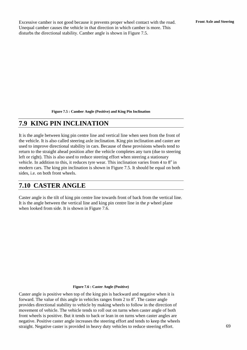
69
Front Axle and Steering Excessive camber is not good because it prevents proper wheel contact with the road.
Unequal camber causes the vehicle in that direction in which camber is more. This
disturbs the directional stability. Camber angle is shown in Figure 7.5.
Figure 7.5 : Camber Angle (Positive) and King Pin Inclination
7.9 KING PIN INCLINATION
It is the angle between king pin centre line and vertical line when seen from the front of
the vehicle. It is also called steering axle inclination. King pin inclination and caster are
used to improve directional stability in cars. Because of these provisions wheels tend to
return to the straight ahead position after the vehicle completes any turn (due to steering
left or right). This is also used to reduce steering effort when steering a stationary
vehicle. In addition to this, it reduces tyre wear. This inclination varies from 4 to 8o in
modern cars. The king pin inclination is shown in Figure 7.5. It should be equal on both
sides, i.e. on both front wheels.
7.10 CASTER ANGLE
Caster angle is the tilt of king pin centre line towards front of back from the vertical line.
It is the angle between the vertical line and king pin centre line in the p wheel plane
when looked from side. It is shown in Figure 7.6.
Figure 7.6 : Caster Angle (Positive)
Caster angle is positive when top of the king pin is backward and negative when it is
forward. The value of this angle in vehicles ranges from 2 to 8o. The caster angle
provides directional stability to vehicle by making wheels to follow in the direction of
movement of vehicle. The vehicle tends to roll out on turns when caster angle of both
front wheels is positive. But it tends to back or lean in on turns when caster angles are
negative. Positive caster angle increases the steering effort and tends to keep the wheels
straight. Negative caster is provided in heavy duty vehicles to reduce steering effort.
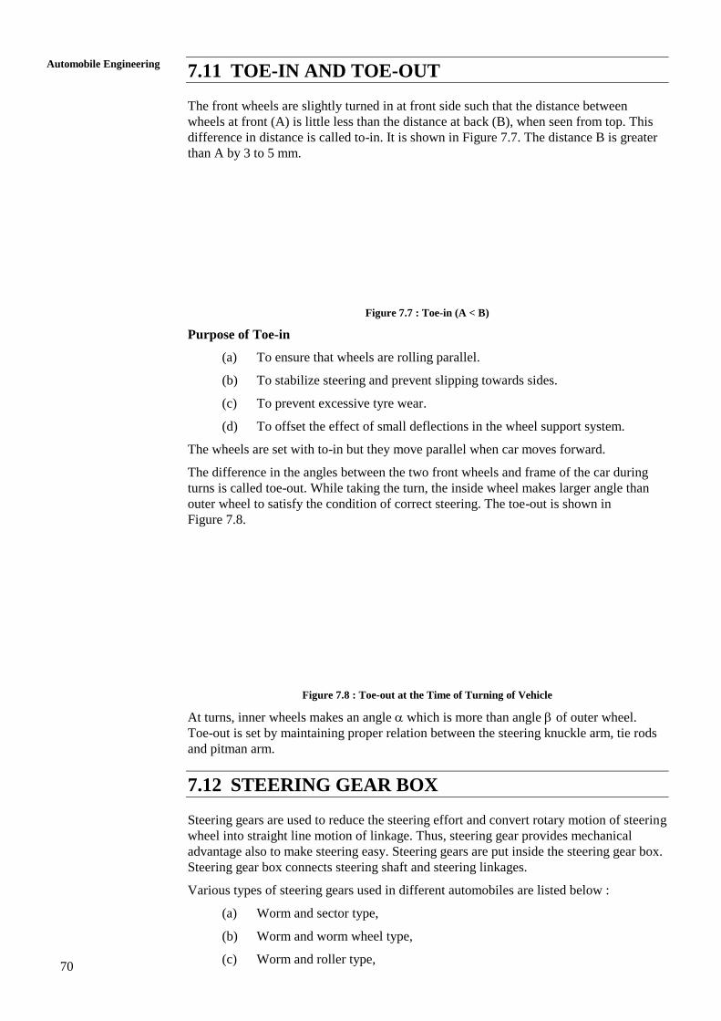
70
Automobile Engineering
7.11 TOE-IN AND TOE-OUT
The front wheels are slightly turned in at front side such that the distance between
wheels at front (A) is little less than the distance at back (B), when seen from top. This
difference in distance is called to-in. It is shown in Figure 7.7. The distance B is greater
than A by 3 to 5 mm.
Figure 7.7 : Toe-in (A < B)
Purpose of Toe-in
(a) To ensure that wheels are rolling parallel.
(b) To stabilize steering and prevent slipping towards sides.
(c) To prevent excessive tyre wear.
(d) To offset the effect of small deflections in the wheel support system.
The wheels are set with to-in but they move parallel when car moves forward.
The difference in the angles between the two front wheels and frame of the car during
turns is called toe-out. While taking the turn, the inside wheel makes larger angle than
outer wheel to satisfy the condition of correct steering. The toe-out is shown in
Figure 7.8.
Figure 7.8 : Toe-out at the Time of Turning of Vehicle
At turns, inner wheels makes an angle which is more than angle of outer wheel.
Toe-out is set by maintaining proper relation between the steering knuckle arm, tie rods
and pitman arm.
7.12 STEERING GEAR BOX
Steering gears are used to reduce the steering effort and convert rotary motion of steering
wheel into straight line motion of linkage. Thus, steering gear provides mechanical
advantage also to make steering easy. Steering gears are put inside the steering gear box.
Steering gear box connects steering shaft and steering linkages.
Various types of steering gears used in different automobiles are listed below :
(a) Worm and sector type,
(b) Worm and worm wheel type,
(c) Worm and roller type,
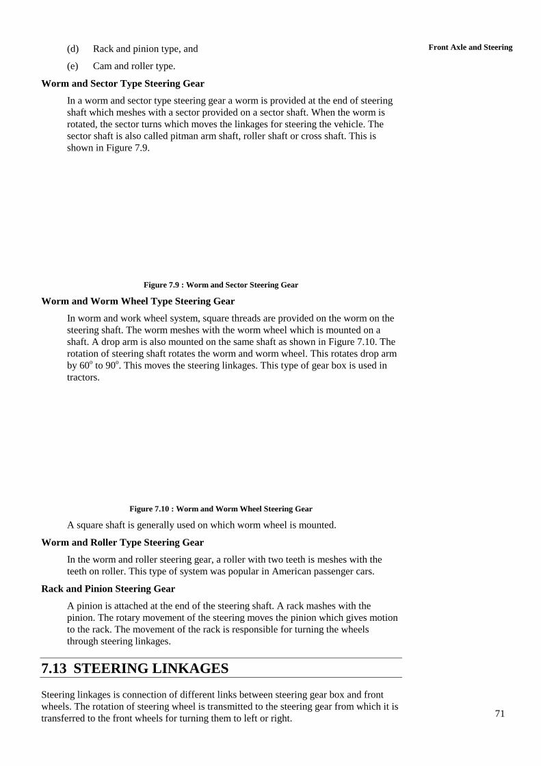
71
Front Axle and Steering (d) Rack and pinion type, and
(e) Cam and roller type.
Worm and Sector Type Steering Gear
In a worm and sector type steering gear a worm is provided at the end of steering
shaft which meshes with a sector provided on a sector shaft. When the worm is
rotated, the sector turns which moves the linkages for steering the vehicle. The
sector shaft is also called pitman arm shaft, roller shaft or cross shaft. This is
shown in Figure 7.9.
Figure 7.9 : Worm and Sector Steering Gear
Worm and Worm Wheel Type Steering Gear
In worm and work wheel system, square threads are provided on the worm on the
steering shaft. The worm meshes with the worm wheel which is mounted on a
shaft. A drop arm is also mounted on the same shaft as shown in Figure 7.10. The
rotation of steering shaft rotates the worm and worm wheel. This rotates drop arm
by 60o to 90
o. This moves the steering linkages. This type of gear box is used in
tractors.
Figure 7.10 : Worm and Worm Wheel Steering Gear
A square shaft is generally used on which worm wheel is mounted.
Worm and Roller Type Steering Gear
In the worm and roller steering gear, a roller with two teeth is meshes with the
teeth on roller. This type of system was popular in American passenger cars.
Rack and Pinion Steering Gear
A pinion is attached at the end of the steering shaft. A rack mashes with the
pinion. The rotary movement of the steering moves the pinion which gives motion
to the rack. The movement of the rack is responsible for turning the wheels
through steering linkages.
7.13 STEERING LINKAGES
Steering linkages is connection of different links between steering gear box and front
wheels. The rotation of steering wheel is transmitted to the steering gear from which it is
transferred to the front wheels for turning them to left or right.
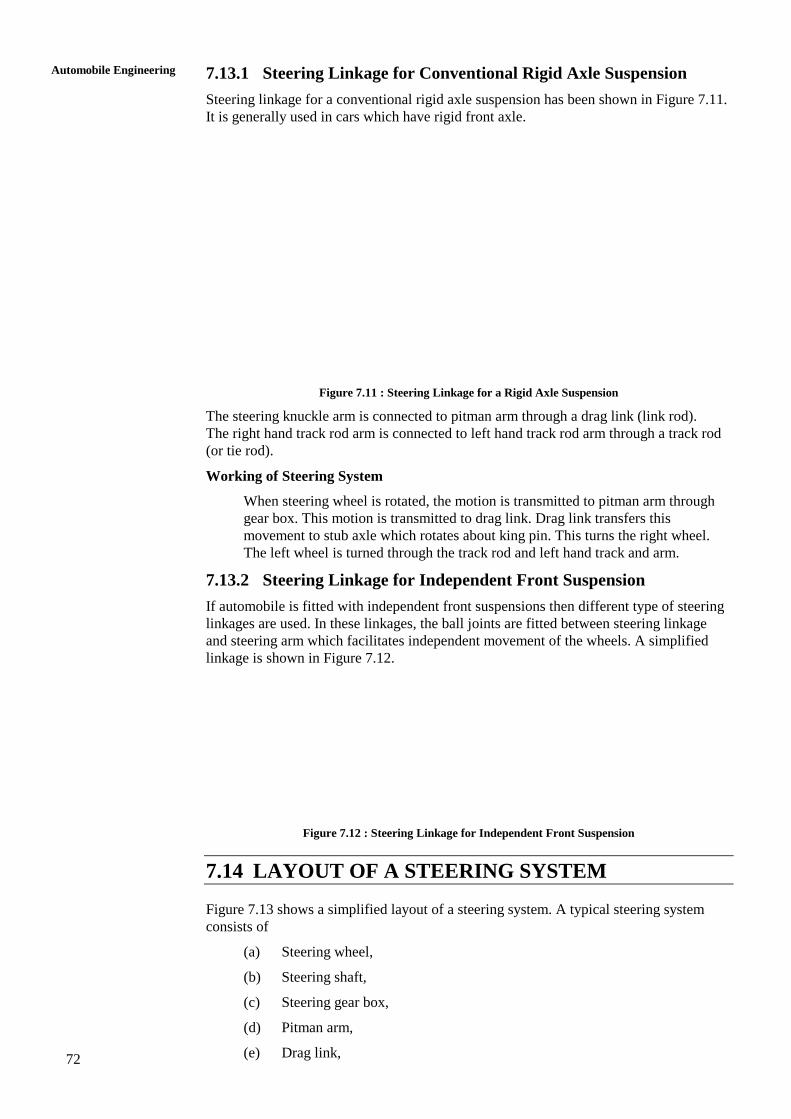
72
Automobile Engineering
7.13.1 Steering Linkage for Conventional Rigid Axle Suspension
Steering linkage for a conventional rigid axle suspension has been shown in Figure 7.11.
It is generally used in cars which have rigid front axle.
Figure 7.11 : Steering Linkage for a Rigid Axle Suspension
The steering knuckle arm is connected to pitman arm through a drag link (link rod).
The right hand track rod arm is connected to left hand track rod arm through a track rod
(or tie rod).
Working of Steering System
When steering wheel is rotated, the motion is transmitted to pitman arm through
gear box. This motion is transmitted to drag link. Drag link transfers this
movement to stub axle which rotates about king pin. This turns the right wheel.
The left wheel is turned through the track rod and left hand track and arm.
7.13.2 Steering Linkage for Independent Front Suspension
If automobile is fitted with independent front suspensions then different type of steering
linkages are used. In these linkages, the ball joints are fitted between steering linkage
and steering arm which facilitates independent movement of the wheels. A simplified
linkage is shown in Figure 7.12.
Figure 7.12 : Steering Linkage for Independent Front Suspension
7.14 LAYOUT OF A STEERING SYSTEM
Figure 7.13 shows a simplified layout of a steering system. A typical steering system
consists of
(a) Steering wheel,
(b) Steering shaft,
(c) Steering gear box,
(d) Pitman arm,
(e) Drag link,
73
Front Axle and Steering (f) Steering knuckle arm,
(g) Tie rod, and
(h) Track rod arm, etc.
Figure 7.13 : Layout of a Steering System
SAQ 1
(a) Write the functions of steering in an automobile.
(b) Name different types of steering gear boxes.
(c) Describes worm and sector type steering gear box.
(d) What is the function of steering linkage? Describe the working of steering
linkage for rigid axle suspension.
(e) Draw a line diagram of a steering linkage for independent front suspension
type vehicle.
SAQ 2
(a) Sketch a line diagram showing the layout of a steering system. List the main
parts of which it consists.
(b) Write the Ackerman’s principle of steering. Show with the help of a
diagram when vehicle takes a right turn.
(c) Explain tow-in and toe-out with the help of suitable diagrams.
(d) Explain the following terms with the help of diagrams :
(i) Caster,
(ii) Camber and
(iii) King pin inclination.
SAQ 3
(a) What do you mean by steering geometry? Explain.
(b) Write the functions of front axle.
(c) What do you mean by :
(i) Line axle, and
(ii) Dead axle.
74
Automobile Engineering
(d) What is the function of stub axles? Describe their use and list different
types.
(e) Why the following provisions made in the vehicle :
(i) Toe-in,
(ii) Toe-out,
(iii) King pin inclination,
(iv) Camber angle, and
(v) Caster angle.
7.15 SUMMARY
7.16 KEY WORDS
7.17 ANSWERS TO SAQs
Refer the preceding text for all the Answers to SAQs.
75
Frame and Chassis
UNIT 8 FRAME AND CHASSIS
Structure
8.1 Introduction
Objectives
8.2 Chassis
8.3 Frame
8.4 Types of Frame
8.4.1 Conventional Frame
8.4.2 Semi-integral Frame
8.4.3 Integral Frame or Frame-less Construction
8.5 Types of Sections used in Frames
8.6 Suspension System
8.7 Functions of Suspension System
8.8 Springs
8.9 Leaf Springs
8.10 Coil Springs
8.11 Torsion Bars
8.12 Shock Absorbers
8.13 Tyres
8.14 Types of Tyres
8.15 Tyre Specification
8.16 Causes of Tyre Wear
8.17 Remedies for Reducing Tyre Wear
8.18 Summary
8.19 Key Words
8.20 Answers to SAQs
8.1 INTRODUCTION
The automobiles such as cars, buses and trucks, etc. are generally considered to be
consisting of two major assemblies, chassis and body.
Objectives
After studying this unit, you should be able to
define chassis, frame, springs, shock absorbers,
explain the various types of frames, springs, and
describe the advantages and disadvantages of tyres, springs and shock
absorbers.
8.2 CHASSIS
Chassis is a French term which is now denotes the whole vehicle except body in case of
heavy vehicles. In case of light vehicles of mono construction, it denotes the whole
vehicle except additional fittings in the body.
“Chassis consists of engine, power train, brakes, steering system and wheels mounted on
a frame”.
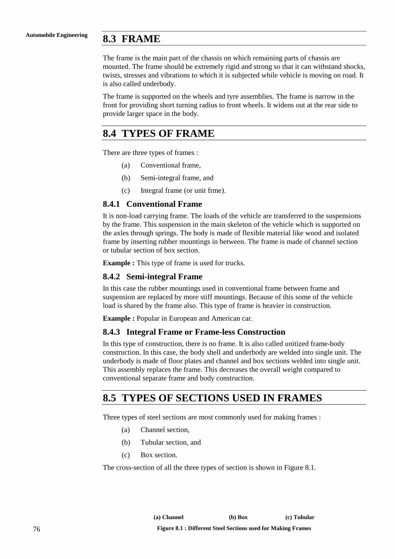
76
Automobile Engineering
8.3 FRAME
The frame is the main part of the chassis on which remaining parts of chassis are
mounted. The frame should be extremely rigid and strong so that it can withstand shocks,
twists, stresses and vibrations to which it is subjected while vehicle is moving on road. It
is also called underbody.
The frame is supported on the wheels and tyre assemblies. The frame is narrow in the
front for providing short turning radius to front wheels. It widens out at the rear side to
provide larger space in the body.
8.4 TYPES OF FRAME
There are three types of frames :
(a) Conventional frame,
(b) Semi-integral frame, and
(c) Integral frame (or unit frme).
8.4.1 Conventional Frame
It is non-load carrying frame. The loads of the vehicle are transferred to the suspensions
by the frame. This suspension in the main skeleton of the vehicle which is supported on
the axles through springs. The body is made of flexible material like wood and isolated
frame by inserting rubber mountings in between. The frame is made of channel section
or tubular section of box section.
Example : This type of frame is used for trucks.
8.4.2 Semi-integral Frame
In this case the rubber mountings used in conventional frame between frame and
suspension are replaced by more stiff mountings. Because of this some of the vehicle
load is shared by the frame also. This type of frame is heavier in construction.
Example : Popular in European and American car.
8.4.3 Integral Frame or Frame-less Construction
In this type of construction, there is no frame. It is also called unitized frame-body
construction. In this case, the body shell and underbody are welded into single unit. The
underbody is made of floor plates and channel and box sections welded into single unit.
This assembly replaces the frame. This decreases the overall weight compared to
conventional separate frame and body construction.
8.5 TYPES OF SECTIONS USED IN FRAMES
Three types of steel sections are most commonly used for making frames :
(a) Channel section,
(b) Tubular section, and
(c) Box section.
The cross-section of all the three types of section is shown in Figure 8.1.
(a) Channel (b) Box (c) Tubular
Figure 8.1 : Different Steel Sections used for Making Frames
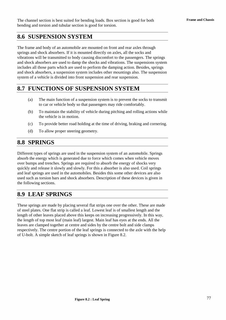
77
Frame and Chassis The channel section is best suited for bending loads. Box section is good for both
bending and torsion and tubular section is good for torsion.
8.6 SUSPENSION SYSTEM
The frame and body of an automobile are mounted on front and rear axles through
springs and shock absorbers. If it is mounted directly on axles, all the socks and
vibrations will be transmitted to body causing discomfort to the passengers. The springs
and shock absorbers are used to damp the shocks and vibrations. The suspensions system
includes all those parts which are used to perform the damping action. Besides, springs
and shock absorbers, a suspension system includes other mountings also. The suspension
system of a vehicle is divided into front suspension and rear suspension.
8.7 FUNCTIONS OF SUSPENSION SYSTEM
(a) The main function of a suspension system is to prevent the socks to transmit
to car or vehicle body so that passengers may ride comfortably.
(b) To maintain the stability of vehicle during pitching and rolling actions while
the vehicle is in motion.
(c) To provide better road holding at the time of driving, braking and cornering.
(d) To allow proper steering geometry.
8.8 SPRINGS
Different types of springs are used in the suspension system of an automobile. Springs
absorb the energy which is generated due to force which comes when vehicle moves
over bumps and trenches. Springs are required to absorb the energy of shocks very
quickly and release it slowly and slowly. For this a absorber is also used. Coil springs
and leaf springs are used in the automobiles. Besides this some other devices are also
used such as torsion bars and shock absorbers. Description of these devices is given in
the following sections.
8.9 LEAF SPRINGS
These springs are made by placing several flat strips one over the other. These are made
of steel plates. One flat strip is called a leaf. Lowest leaf is of smallest length and the
length of other leaves placed above this keeps on increasing progressively. In this way,
the length of top most leaf (main leaf) largest. Main leaf has eyes at the ends. All the
leaves are clamped together at centre and sides by the centre bolt and side clamps
respectively. The centre portion of the leaf springs is connected to the axle with the help
of U-bolt. A simple sketch of leaf springs is shown in Figure 8.2.
Figure 8.2 : Leaf Spring
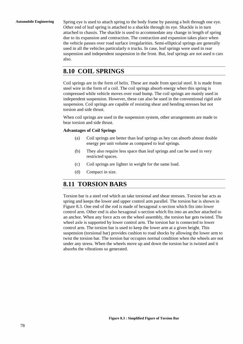
78
Automobile Engineering
Spring eye is used to attach spring to the body frame by passing a bolt through one eye.
Other end of leaf spring is attached to a shackle through its eye. Shackle is in turn
attached to chassis. The shackle is used to accommodate any change in length of spring
due to its expansion and contraction. The contraction and expansion takes place when
the vehicle passes over road surface irregularities. Semi-elliptical springs are generally
used in all the vehicles particularly n trucks. In case, leaf springs were used in rear
suspension and independent suspension in the front. But, leaf springs are not used n cars
also.
8.10 COIL SPRINGS
Coil springs are in the form of helix. These are made from special steel. It is made from
steel wire in the form of a coil. The coil springs absorb energy when this spring is
compressed while vehicle moves over road bump. The coil springs are mainly used in
independent suspension. However, these can also be used in the conventional rigid axle
suspension. Coil springs are capable of resisting shear and bending stresses but not
torsion and side thrust.
When coil springs are used in the suspension system, other arrangements are made to
bear torsion and side thrust.
Advantages of Coil Springs
(a) Coil springs are better than leaf springs as hey can absorb almost double
energy per unit volume as compared to leaf springs.
(b) They also require less space than leaf springs and can be used in very
restricted spaces.
(c) Coil springs are lighter in weight for the same load.
(d) Compact in size.
8.11 TORSION BARS
Torsion bar is a steel rod which an take torsional and shear stresses. Torsion bar acts as
spring and keeps the lower and upper control arm parallel. The torsion bar is shown in
Figure 8.3. One end of the rod is made of hexagonal x-section which fits into lower
control arm. Other end is also hexagonal x-section which fits into an anchor attached to
an anchor. When any force acts on the wheel assembly, the torsion bar gets twisted. The
wheel axle is supported by lower control arm. The torsion bar is connected to lower
control arm. The torsion bar is used to keep the lower arm at a given height. This
suspension (torsional bar) provides cushion to road shocks by allowing the lower arm to
twist the torsion bar. The torsion bar occupies normal condition when the wheels are not
under any stress. When the wheels move up and down the torsion bar is twisted and it
absorbs the vibrations so generated.
Figure 8.3 : Simplified Figure of Torsion Bar
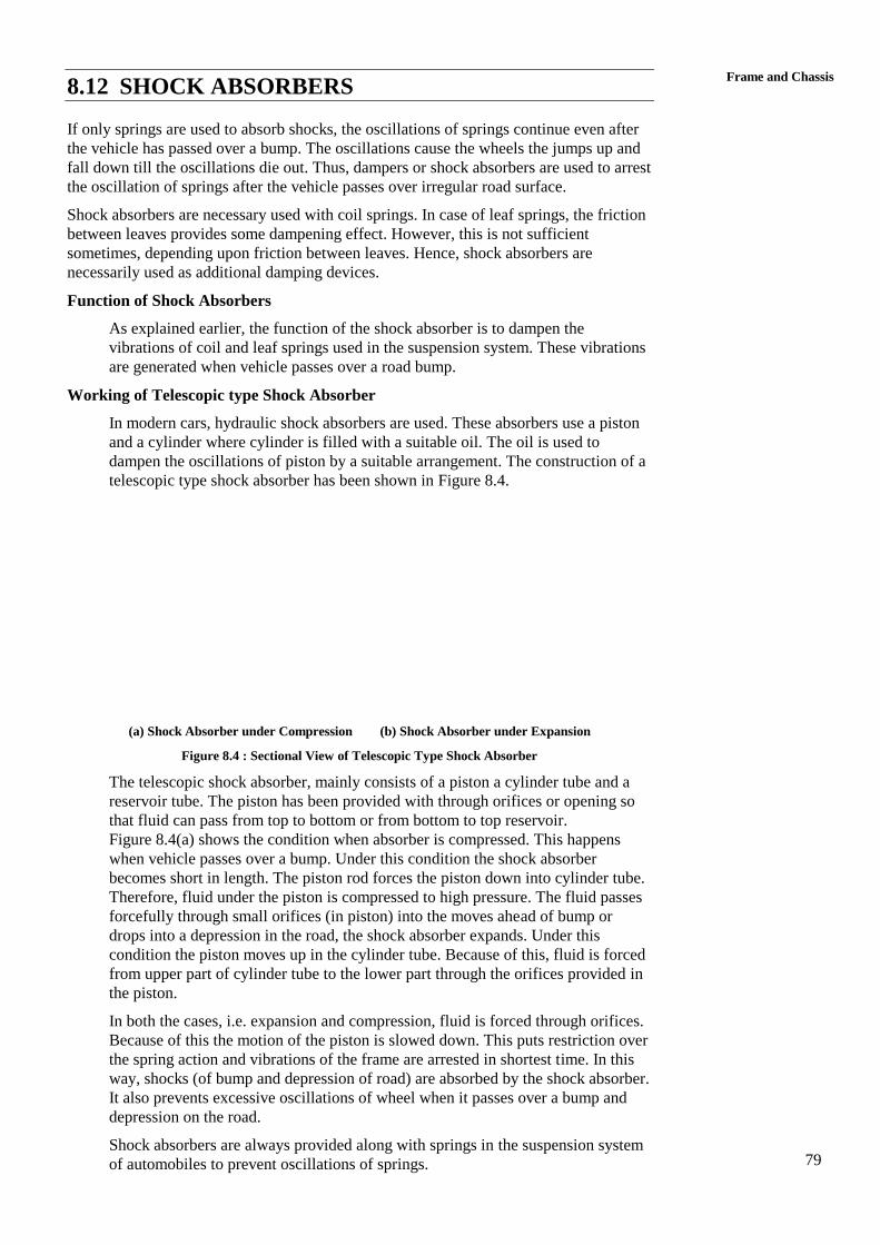
79
Frame and Chassis 8.12 SHOCK ABSORBERS
If only springs are used to absorb shocks, the oscillations of springs continue even after
the vehicle has passed over a bump. The oscillations cause the wheels the jumps up and
fall down till the oscillations die out. Thus, dampers or shock absorbers are used to arrest
the oscillation of springs after the vehicle passes over irregular road surface.
Shock absorbers are necessary used with coil springs. In case of leaf springs, the friction
between leaves provides some dampening effect. However, this is not sufficient
sometimes, depending upon friction between leaves. Hence, shock absorbers are
necessarily used as additional damping devices.
Function of Shock Absorbers
As explained earlier, the function of the shock absorber is to dampen the
vibrations of coil and leaf springs used in the suspension system. These vibrations
are generated when vehicle passes over a road bump.
Working of Telescopic type Shock Absorber
In modern cars, hydraulic shock absorbers are used. These absorbers use a piston
and a cylinder where cylinder is filled with a suitable oil. The oil is used to
dampen the oscillations of piston by a suitable arrangement. The construction of a
telescopic type shock absorber has been shown in Figure 8.4.
(a) Shock Absorber under Compression (b) Shock Absorber under Expansion
Figure 8.4 : Sectional View of Telescopic Type Shock Absorber
The telescopic shock absorber, mainly consists of a piston a cylinder tube and a
reservoir tube. The piston has been provided with through orifices or opening so
that fluid can pass from top to bottom or from bottom to top reservoir.
Figure 8.4(a) shows the condition when absorber is compressed. This happens
when vehicle passes over a bump. Under this condition the shock absorber
becomes short in length. The piston rod forces the piston down into cylinder tube.
Therefore, fluid under the piston is compressed to high pressure. The fluid passes
forcefully through small orifices (in piston) into the moves ahead of bump or
drops into a depression in the road, the shock absorber expands. Under this
condition the piston moves up in the cylinder tube. Because of this, fluid is forced
from upper part of cylinder tube to the lower part through the orifices provided in
the piston.
In both the cases, i.e. expansion and compression, fluid is forced through orifices.
Because of this the motion of the piston is slowed down. This puts restriction over
the spring action and vibrations of the frame are arrested in shortest time. In this
way, shocks (of bump and depression of road) are absorbed by the shock absorber.
It also prevents excessive oscillations of wheel when it passes over a bump and
depression on the road.
Shock absorbers are always provided along with springs in the suspension system
of automobiles to prevent oscillations of springs.
80
Automobile Engineering
8.13 TYRES
Tyres are mounted on the rims of wheels. They enclose a tube between rim and itself.
Air is filled at a designated pressure inside the tube. The tyre remains inflated due to air
pressure inside tube. The tyre carries the vehicle load and provides cushioning effect. It
absorbs some of the vibrations generated due to vehicle’s movement on uneven surfaces.
It also resists the vehicle’s tendency to over steer or turn which cornering. Tyre must
generate minimum noise when vehicle takes turn on the road. It should provide good grip
with the road surface under all conditions.
8.14 TYPES OF TYRES
Two types of tyres are used in vehicles :
(a) Tube tyres, and
(b) Tubeless tyres.
Both these tyres are called pneumatic tyres because air is filled in them.
Tube Tyres
Tube tyres encloses a tube which is wrapped on the wheel rim. Air is forced into
tube which inflates the tube and tyre. The outer side of tyre which comes in
contact of road is made from rubber. It is called tread. Tread provides resistance to
slipping. It is very thick at the outer periphery. Beads are made at the inner bide by
reinforcing it with steel wires. Beads are very strong which have good resistance
to wearing against the wheel rim. Rayon cords are also formed into a number of
piles. Beads are cords provide good strength to tyres.
Tubeless Tyres
These tyres do not require any tube. The air at pressure is filled into the tyre itself.
The construction of tyre is same as that of tube tyre. For filling the air, a
non-return valve is filled in the tyre itself.
Advantages of Tubeless Tyres
(a) Tubeless tyres are lighter in weight.
(b) They remain cooler compared to tube tyres.
(c) The main advantage of tubeless tyre is that they remain inflated for
long time even if these are punctured by a nail if the nail remains
inside the tyre.
(d) Any hole in the tyre, due to puncture, can be repaired by rubber
plugging.
(e) A simple puncture can be repaired without removing tyre from wheel.
8.15 TYRE SPECIFICATION
Every tyre is specified by its size. Its specification is given as follows :
8.25 30 6 PR
Meaning of these Numbers
(a) 8.25 : It mean that thickness of tyre from shoulder to shoulder is
8.25 inches.
(b) 20 : It means that diameter of bead circle is 20 inches.
(c) 6 PR : It means that six ply rating. It means that tyre cosists of 6 plies.
Different type of tyres have different plies. Number of plies increase as load
increases, e.g. a ca tyre has 4 to 6 plies and a light truck may have 6 to
10 plies.
81
Frame and Chassis 8.16 CAUSES OF TYRE WEAR
Excessive tyre wear is caused due to reasons discussed below :
(a) Lower or Higher Tyre Pressure : It is recommended by manufacturer’s to
maintain correct tyre pressure. If the tyre pressure is perfect, there will be
full tread contact with the road. If tyre pressure is lower than required,
severe flexing of tyre piles, and side walls take place. In this case, excessive
heat is generated which causes excessive wear. Tyres wear out more on
both sides of tread and less of centre.
If tyre pressure is higher, the tyres wear out more at centre and les son sides.
(b) Tyres wear out more one on side than the reason is incorrect caber setting.
(c) Toe-out causes remarkable wear on tread inner end of both front wheels.
(d) High speed of vehicle is also the cause of more tyre wear and failure.
8.17 REMEDIES FOR REDUCING TYRE WEAR
(a) Maintaining correct tyre pressure.
(b) Correct camber.
(c) Proper wheel alignment.
(d) If vehicle is to be run at very high speeds tyre must be little over inflated to
reduce wear.
(e) Steering must be properly adjusted.
(f) Avoid habit of turning at higher speeds.
SAQ 1
(a) What do you mean by Chassis? Describe.
(b) What are the functions of frame?
(c) List various types of frame and describe in brief the conventional frame.
(d) What do you mean by frameless construction? Describe in brief.
(e) Differentiate between integral and semi-integral frame.
SAQ 2
(a) What are functions of suspension system of an automobile?
(b) What is the function of torsion bar suspension? How does it work? Explain
in brief.
(c) Describe a leaf spring suspension system.
(d) Describe a coil spring suspension system.
(e) What is the function of a shock absorber? How does a hydraulic shock
absorber work?
82
Automobile Engineering
SAQ 3
(a) Describe in brief various types of tyres?
(b) List the advantages of tubeless of tyres?
(c) How the tyres are specified? Explain with the help of an example.
(d) What are different causes of tyre wear? Describe.
(f) How can you reduce type wear of your vehicle?
8.18 SUMMARY
In this unit, you must have gain the knowledge about the chassis and frame. Chassis and
frames are the two main parts of the automobiles. Any automobile engineering should
have the knowledge about the automobile parts and its main functions. You must have
understood about the functions and uses of chasses, frame, springs, tyres and shock
absorbers. This unit given you the knowledge on different types of spring, tyres, shock
absorbers and its functions as a automobile parts and components.
8.19 KEY WORDS
8.20 ANSWERS TO SAQs
efer the preceding text for all the Answers to SAQs.
83
Frame and Chassis
FURTHER READING
William H. Crouse and Donald L. Anglin, Automotive Engines, McGraw Hill.
K. K. Jain and R. B. Asthan, Automobile Engineering, Tata McGraw Hill.
R. K. Rajput, Automobile Engineering, Laxmi Publications Pvt. Ltd.
Siegfried Herrmann, Automotive Engineering, Asia publishing House.
P. L. Ballaney, Theory of Machines, (For Numerical on Gear Trains).

84
Automobile Engineering
85
Frame and Chassis
AUTOMOBILE ENGINEERING