Embed Size (px)
Citation preview

AUTO M ATION STA RTERSA7
INSTRUCTION MANUAL
REV 11/03 P/N: 027-2063November 2003© Copyright TECO-Westinghouse Motor Company 2003TECO-Westinghouse Motor Company retains the right to change specifications and illustrationsin the text, without prior notification. The contents of this document may not be copied without theexplicit permission of TECO-Westinghouse Motor Company.

SAFETY INSTRUCTIONS
SA7 Instruction Manual
' 2003 TECO-Westinghouse Motor Company2
SafetyThe soft starter should be installed in a cabinet or in an electrical control room.
The device must be installed by trained personnel. Disconnect all power sources before servicing. Short circuit protection in the form of circuit breaker or time delay fuses must be provided per code.
Operating and Maintenance Personnel1. Read the whole Instruction Manual before installing and putting the equipment into operation. 2. During all work (operation, maintenance, repairs, etc.) observe the switch-off procedures given in this
instruction as well as any other operating instruction for the driven machine or system. See Emergency below.
3. The operator must avoid any working methods which reduce the safety of the device.4. The operator must do what he can to ensure that no unauthorised person is working on the device.5. The operator must immediately report any changes to the device which reduce its safety to the user.6. The user must undertake all necessary measures to operate the device in perfect condition only.
Installation of Spare PartsW e expressly point out that any spare parts and accessories not supplied by Saftronics, Inc. have also not beentested or approved by Saftronics, Inc.Installing and/or using such products can have a negative effect on the characteristics designed for your device. Themanufacturer is not liable for damage arising as a result of using non-original parts and accessories.
EmergencyYou can switch the device off at any time with the mains switch connected in front of the soft starter (both motor andcontrol voltage should be switched off).
Dismantling and ScrappingThe enclosure of the soft starter is made of recyclable material, such as aluminium, iron and plastic. Legal require-ments for disposal and recycling of these materials must be complied with.The soft starter contains a number of components demanding special treatment, as for example thyristors. The cir-cuit board contain small amounts of tin and lead. Legal requirements for disposal and recycling of these materialsmust be complied with.

SA7 Instruction Manual
' 2003 TECO-Westinghouse Motor Company 3
TABLE OF CONTENTS
TABLE OF CONTENTS
1.0 GENERAL INFORMATION . . . . . . . . . . . . . . . . . . . . . . . . . . . . . . . . . . . . . . . . .71.1 Integrated safety systems . . . . . . . . . . . . . . . . . . . . . . . . . . . . . . . . . . . . . . . . .71.2 Safety measures . . . . . . . . . . . . . . . . . . . . . . . . . . . . . . . . . . . . . . . . . . . . . . . .71.3 Notes to the Instruction Manual . . . . . . . . . . . . . . . . . . . . . . . . . . . . . . . . . . . . .71.4 How to use the Instruction Manual . . . . . . . . . . . . . . . . . . . . . . . . . . . . . . . . . . .81.5 Standards . . . . . . . . . . . . . . . . . . . . . . . . . . . . . . . . . . . . . . . . . . . . . . . . . . . . .81.6 Tests in accordance with norm EN60204 . . . . . . . . . . . . . . . . . . . . . . . . . . . . . .81.7 Inspection at delivery . . . . . . . . . . . . . . . . . . . . . . . . . . . . . . . . . . . . . . . . . . . . .81.7.1 Transport and packing . . . . . . . . . . . . . . . . . . . . . . . . . . . . . . . . . . . . . . . . . . . .82.0 DESCRIPTION . . . . . . . . . . . . . . . . . . . . . . . . . . . . . . . . . . . . . . . . . . . . . . . .102.1 General . . . . . . . . . . . . . . . . . . . . . . . . . . . . . . . . . . . . . . . . . . . . . . . . . . . . . .102.2 AS6 control methods . . . . . . . . . . . . . . . . . . . . . . . . . . . . . . . . . . . . . . . . . . . .122.2.1 General features . . . . . . . . . . . . . . . . . . . . . . . . . . . . . . . . . . . . . . . . . . . . . . .123.0 HOW TO GET STARTED . . . . . . . . . . . . . . . . . . . . . . . . . . . . . . . . . . . . . . . . .133.1 Checklist . . . . . . . . . . . . . . . . . . . . . . . . . . . . . . . . . . . . . . . . . . . . . . . . . . . . .133.2 Main functions/Applications . . . . . . . . . . . . . . . . . . . . . . . . . . . . . . . . . . . . . . .143.3 Motor Data . . . . . . . . . . . . . . . . . . . . . . . . . . . . . . . . . . . . . . . . . . . . . . . . . . . .143.4 Setting of the start and stop ramps . . . . . . . . . . . . . . . . . . . . . . . . . . . . . . . . . .153.5 Setting the start command . . . . . . . . . . . . . . . . . . . . . . . . . . . . . . . . . . . . . . . .163.6 Viewing the motor current . . . . . . . . . . . . . . . . . . . . . . . . . . . . . . . . . . . . . . . . .163.7 Starting . . . . . . . . . . . . . . . . . . . . . . . . . . . . . . . . . . . . . . . . . . . . . . . . . . . . . .174.0 APPLICATION AND FUNCTION SELECTION . . . . . . . . . . . . . . . . . . . . . . . . .184.1 Soft starter rating . . . . . . . . . . . . . . . . . . . . . . . . . . . . . . . . . . . . . . . . . . . . . . .184.2 The application ratings list . . . . . . . . . . . . . . . . . . . . . . . . . . . . . . . . . . . . . . . .184.3 The application functions list . . . . . . . . . . . . . . . . . . . . . . . . . . . . . . . . . . . . . .194.4 Function and combination matrix . . . . . . . . . . . . . . . . . . . . . . . . . . . . . . . . . . .224.5 Special condition . . . . . . . . . . . . . . . . . . . . . . . . . . . . . . . . . . . . . . . . . . . . . . .234.5.1 Small motor or low load . . . . . . . . . . . . . . . . . . . . . . . . . . . . . . . . . . . . . . . . . .234.5.2 Ambient temperature below 0oC . . . . . . . . . . . . . . . . . . . . . . . . . . . . . . . . . . . .234.5.3 Power Factor Correction Capacitor . . . . . . . . . . . . . . . . . . . . . . . . . . . . . . . . . .234.5.4 Pole-changing contactor and two speed motor . . . . . . . . . . . . . . . . . . . . . . . . .234.5.5 Shielded motor cable . . . . . . . . . . . . . . . . . . . . . . . . . . . . . . . . . . . . . . . . . . . .234.5.6 Slip ring motors . . . . . . . . . . . . . . . . . . . . . . . . . . . . . . . . . . . . . . . . . . . . . . . .234.5.7 Pump control with soft starter and frequency inverter together . . . . . . . . . . . . .234.5.8 Starting with counter clockwise rotating loads . . . . . . . . . . . . . . . . . . . . . . . . . .244.5.9 Running motors in parallel . . . . . . . . . . . . . . . . . . . . . . . . . . . . . . . . . . . . . . . .244.5.10 How to calculate heat dissipation in cabinets . . . . . . . . . . . . . . . . . . . . . . . . . . .244.5.11 Insulation test on motor . . . . . . . . . . . . . . . . . . . . . . . . . . . . . . . . . . . . . . . . . .244.5.12 Operation above 1000 m . . . . . . . . . . . . . . . . . . . . . . . . . . . . . . . . . . . . . . . . .244.5.13 Reversing . . . . . . . . . . . . . . . . . . . . . . . . . . . . . . . . . . . . . . . . . . . . . . . . . . . .245.0 OPERATION OF THE SOFT STARTER . . . . . . . . . . . . . . . . . . . . . . . . . . . . . .255.1 General description of user interface . . . . . . . . . . . . . . . . . . . . . . . . . . . . . . . .255.2 PPU unit . . . . . . . . . . . . . . . . . . . . . . . . . . . . . . . . . . . . . . . . . . . . . . . . . . . . .255.3 LED display . . . . . . . . . . . . . . . . . . . . . . . . . . . . . . . . . . . . . . . . . . . . . . . . . . .265.4 The Menu Structure . . . . . . . . . . . . . . . . . . . . . . . . . . . . . . . . . . . . . . . . . . . . .265.5 The keys . . . . . . . . . . . . . . . . . . . . . . . . . . . . . . . . . . . . . . . . . . . . . . . . . . . . .275.6 Keyboard lock . . . . . . . . . . . . . . . . . . . . . . . . . . . . . . . . . . . . . . . . . . . . . . . . .275.7 Overview of soft starter operation and parameter set-up. . . . . . . . . . . . . . . . . .286.0 INSTALLATION AND CONNECTION . . . . . . . . . . . . . . . . . . . . . . . . . . . . . . . .286.1 Installation of the soft starter in a cabinet . . . . . . . . . . . . . . . . . . . . . . . . . . . . .28

TABLE OF CONTENTS
SA7 Instruction Manual
' 2003 TECO-Westinghouse Motor Company4
6.2 Connections . . . . . . . . . . . . . . . . . . . . . . . . . . . . . . . . . . . . . . . . . . . . . . . . . . .316.3 Connection and setting on the PCB control card . . . . . . . . . . . . . . . . . . . . . . . .346.4 Minimum wiring . . . . . . . . . . . . . . . . . . . . . . . . . . . . . . . . . . . . . . . . . . . . . . . .356.5 W iring examples . . . . . . . . . . . . . . . . . . . . . . . . . . . . . . . . . . . . . . . . . . . . . . . .367.0 FUNCTIONAL DESCRIPTION SET-UP MENU . . . . . . . . . . . . . . . . . . . . . . . . .377.1 Ramp up/down parameters . . . . . . . . . . . . . . . . . . . . . . . . . . . . . . . . . . . . . . .387.1.1 RMS current [005] . . . . . . . . . . . . . . . . . . . . . . . . . . . . . . . . . . . . . . . . . . . . . .387.2 Start/stop/reset command . . . . . . . . . . . . . . . . . . . . . . . . . . . . . . . . . . . . . . . . .397.2.1 2-wire start/stop with automatic reset at start . . . . . . . . . . . . . . . . . . . . . . . . . .397.2.2 2-wire start/stop with separate reset . . . . . . . . . . . . . . . . . . . . . . . . . . . . . . . . .397.2.3 3-wire start/stop with automatic reset at start. . . . . . . . . . . . . . . . . . . . . . . . . . .397.3 Menu expansion setting. . . . . . . . . . . . . . . . . . . . . . . . . . . . . . . . . . . . . . . . . .407.4 Voltage control dual ramp . . . . . . . . . . . . . . . . . . . . . . . . . . . . . . . . . . . . . . . . .407.5 Torque control parameters . . . . . . . . . . . . . . . . . . . . . . . . . . . . . . . . . . . . . . . .417.6 Current limit (Main Function) . . . . . . . . . . . . . . . . . . . . . . . . . . . . . . . . . . . . . .417.6.1 Voltage ramp with current limit . . . . . . . . . . . . . . . . . . . . . . . . . . . . . . . . . . . . .417.6.2 Current limit . . . . . . . . . . . . . . . . . . . . . . . . . . . . . . . . . . . . . . . . . . . . . . . . . . .427.7 Pump control (Main Function) . . . . . . . . . . . . . . . . . . . . . . . . . . . . . . . . . . . . . .427.8 Analogue Input Control (Main Function) . . . . . . . . . . . . . . . . . . . . . . . . . . . . . .437.9 Full voltage start, D.O.L. (Main Function) . . . . . . . . . . . . . . . . . . . . . . . . . . . . .437.10 Torque control (Main function) . . . . . . . . . . . . . . . . . . . . . . . . . . . . . . . . . . . . .447.11 Torque boost . . . . . . . . . . . . . . . . . . . . . . . . . . . . . . . . . . . . . . . . . . . . . . . . . .457.12 Bypass . . . . . . . . . . . . . . . . . . . . . . . . . . . . . . . . . . . . . . . . . . . . . . . . . . . . . . .457.13 Power Factor Control . . . . . . . . . . . . . . . . . . . . . . . . . . . . . . . . . . . . . . . . . . . .477.14 Brake functions . . . . . . . . . . . . . . . . . . . . . . . . . . . . . . . . . . . . . . . . . . . . . . . .477.15 Slow speed and Jog functions . . . . . . . . . . . . . . . . . . . . . . . . . . . . . . . . . . . . .497.15.1 Slow speed controlled by an external signal. . . . . . . . . . . . . . . . . . . . . . . . . . .497.15.2 Slow speed during a selected time . . . . . . . . . . . . . . . . . . . . . . . . . . . . . . . . . .507.15.3 Jog Functions . . . . . . . . . . . . . . . . . . . . . . . . . . . . . . . . . . . . . . . . . . . . . . . . .507.15.4 DC-brake after slow speed at stop [040] . . . . . . . . . . . . . . . . . . . . . . . . . . . . . .507.16 Motor data setting . . . . . . . . . . . . . . . . . . . . . . . . . . . . . . . . . . . . . . . . . . . . . .517.17 Programmable relay K1 and K2 . . . . . . . . . . . . . . . . . . . . . . . . . . . . . . . . . . . .527.18 Analogue output . . . . . . . . . . . . . . . . . . . . . . . . . . . . . . . . . . . . . . . . . . . . . . . .537.19 Digital input selection . . . . . . . . . . . . . . . . . . . . . . . . . . . . . . . . . . . . . . . . . . . .547.20 Parameter Set . . . . . . . . . . . . . . . . . . . . . . . . . . . . . . . . . . . . . . . . . . . . . . . . .557.21 Motor protection, overload (F2 alarm) . . . . . . . . . . . . . . . . . . . . . . . . . . . . . . . .567.22 Mains protection . . . . . . . . . . . . . . . . . . . . . . . . . . . . . . . . . . . . . . . . . . . . . . .577.23 Application protection (load monitor) . . . . . . . . . . . . . . . . . . . . . . . . . . . . . . . . .587.23.1 Load monitor max and min/protection (F6 and F7 alarms) . . . . . . . . . . . . . . . .587.23.2 Pre-alarm . . . . . . . . . . . . . . . . . . . . . . . . . . . . . . . . . . . . . . . . . . . . . . . . . . . . .597.24 Resume alarms . . . . . . . . . . . . . . . . . . . . . . . . . . . . . . . . . . . . . . . . . . . . . . . .627.24.1 Phase input failure F1 . . . . . . . . . . . . . . . . . . . . . . . . . . . . . . . . . . . . . . . . . . .627.24.2 Run at current limit time-out F4 . . . . . . . . . . . . . . . . . . . . . . . . . . . . . . . . . . . .627.25 Slow speed with JOG . . . . . . . . . . . . . . . . . . . . . . . . . . . . . . . . . . . . . . . . . . . .627.26 Automatic return menu . . . . . . . . . . . . . . . . . . . . . . . . . . . . . . . . . . . . . . . . . . .637.27 Communication option, related Parameters . . . . . . . . . . . . . . . . . . . . . . . . . . .637.28 Reset to factory setting [199] . . . . . . . . . . . . . . . . . . . . . . . . . . . . . . . . . . . . . .647.29 View operation . . . . . . . . . . . . . . . . . . . . . . . . . . . . . . . . . . . . . . . . . . . . . . . . .647.30 Keyboard lock . . . . . . . . . . . . . . . . . . . . . . . . . . . . . . . . . . . . . . . . . . . . . . . . .667.31 Alarm list . . . . . . . . . . . . . . . . . . . . . . . . . . . . . . . . . . . . . . . . . . . . . . . . . . . . .668.0 PROTECTION AND ALARM . . . . . . . . . . . . . . . . . . . . . . . . . . . . . . . . . . . . . .67

SA7 Instruction Manual
' 2003 TECO-Westinghouse Motor Company 5
TABLE OF CONTENTS
8.1 Alarm description . . . . . . . . . . . . . . . . . . . . . . . . . . . . . . . . . . . . . . . . . . . . . . .678.1.1 Alarm with stop and requiring a separate reset . . . . . . . . . . . . . . . . . . . . . . . . .678.1.2 Alarm with stop and requiring only a new start command . . . . . . . . . . . . . . . . .678.1.3 Alarm with continue run . . . . . . . . . . . . . . . . . . . . . . . . . . . . . . . . . . . . . . . . . .678.2 Alarm overview . . . . . . . . . . . . . . . . . . . . . . . . . . . . . . . . . . . . . . . . . . . . . . . .689.0 TROUBLESHOOTING . . . . . . . . . . . . . . . . . . . . . . . . . . . . . . . . . . . . . . . . . . .699.1 Fault, cause and solution . . . . . . . . . . . . . . . . . . . . . . . . . . . . . . . . . . . . . . . . .6910.0 MAINTENANCE . . . . . . . . . . . . . . . . . . . . . . . . . . . . . . . . . . . . . . . . . . . . . . .7211.0 OPTIONS . . . . . . . . . . . . . . . . . . . . . . . . . . . . . . . . . . . . . . . . . . . . . . . . . . . .7311.1 Serial communication . . . . . . . . . . . . . . . . . . . . . . . . . . . . . . . . . . . . . . . . . . . .7311.2 Field bus systems . . . . . . . . . . . . . . . . . . . . . . . . . . . . . . . . . . . . . . . . . . . . . .7311.3 External PPU. . . . . . . . . . . . . . . . . . . . . . . . . . . . . . . . . . . . . . . . . . . . . . . . . .7312.0 SET-UP MENU LIST . . . . . . . . . . . . . . . . . . . . . . . . . . . . . . . . . . . . . . . . . . . .7413.0 INDEX . . . . . . . . . . . . . . . . . . . . . . . . . . . . . . . . . . . . . . . . . . . . . . . . . . . . . . .77
LIST OF TABLESTable 1 Application Rating List . . . . . . . . . . . . . . . . . . . . . . . . . . . . . . . . . . . . . . . . . . .19Table 2 Application Function List . . . . . . . . . . . . . . . . . . . . . . . . . . . . . . . . . . . . . . . . .21Table 3 Combination matrix . . . . . . . . . . . . . . . . . . . . . . . . . . . . . . . . . . . . . . . . . . . . .22Table 4 Start/stop combination. . . . . . . . . . . . . . . . . . . . . . . . . . . . . . . . . . . . . . . . . . . .23Table 5 The keys . . . . . . . . . . . . . . . . . . . . . . . . . . . . . . . . . . . . . . . . . . . . . . . . . . . . .27Table 6 Control modes . . . . . . . . . . . . . . . . . . . . . . . . . . . . . . . . . . . . . . . . . . . . . . . . .28Table 7 SA7-017 to SA7-250. . . . . . . . . . . . . . . . . . . . . . . . . . . . . . . . . . . . . . . . . . . . .30Table 8 SA7-017 toSA7-250 . . . . . . . . . . . . . . . . . . . . . . . . . . . . . . . . . . . . . . . . . . . . .30Table 9 PCB Terminals . . . . . . . . . . . . . . . . . . . . . . . . . . . . . . . . . . . . . . . . . . . . . . . . .34Table 10 Set-up Menu overview . . . . . . . . . . . . . . . . . . . . . . . . . . . . . . . . . . . . . . . . . . .37
LIST OF FIGURESFig. 1 Scope of delivery. . . . . . . . . . . . . . . . . . . . . . . . . . . . . . . . . . . . . . . . . . . . . . . . .8Fig. 2 Voltage control . . . . . . . . . . . . . . . . . . . . . . . . . . . . . . . . . . . . . . . . . . . . . . . . .10Fig. 3 Current control . . . . . . . . . . . . . . . . . . . . . . . . . . . . . . . . . . . . . . . . . . . . . . . . .11Fig. 4 Torque control . . . . . . . . . . . . . . . . . . . . . . . . . . . . . . . . . . . . . . . . . . . . . . . . .11Fig. 5 Standard wiring. . . . . . . . . . . . . . . . . . . . . . . . . . . . . . . . . . . . . . . . . . . . . . . . .13Fig. 6 Example of start ramp with main function voltage ramp . . . . . . . . . . . . . . . . . .17Fig. 7 PPU unit. . . . . . . . . . . . . . . . . . . . . . . . . . . . . . . . . . . . . . . . . . . . . . . . . . . . . .25Fig. 8 LED indication at different operation situation. . . . . . . . . . . . . . . . . . . . . . . . . .26Fig. 9 Menu structure. . . . . . . . . . . . . . . . . . . . . . . . . . . . . . . . . . . . . . . . . . . . . . . . .26Fig. 10 AS6 dimensions. . . . . . . . . . . . . . . . . . . . . . . . . . . . . . . . . . . . . . . . . . . . . . . .29Fig. 11 Hole pattern for SA7-017 to SA7-250 . . . . . . . . . . . . . . . . . . . . . . . . . . . . . . . .29Fig. 12 Hole pattern for SA7-170 to SA7-250 with upper mounting bracket instead
of DIN-rail. . . . . . . . . . . . . . . . . . . . . . . . . . . . . . . . . . . . . . . . . . . . . . . . . . . . .29Fig. 13 Connection of SA7-017 to SA7-085. . . . . . . . . . . . . . . . . . . . . . . . . . . . . . . . . .31Fig. 14 Connection of SA7-110 to SA7-145. . . . . . . . . . . . . . . . . . . . . . . . . . . . . . . . . .32Fig. 15 Connection of SA7-170 to SA7-250 . . . . . . . . . . . . . . . . . . . . . . . . . . . . . . . . .33Fig. 16 Connections on the PCB, control card. . . . . . . . . . . . . . . . . . . . . . . . . . . . . . . .34Fig. 17 W iring circuit, Minimum wiring . . . . . . . . . . . . . . . . . . . . . . . . . . . . . . . . . . . . .35Fig. 18 Analogue input control, parameter set selection, analogue output . . . . . . . . . . .36Fig. 19 Motor overtemp protection via PTC sensor . . . . . . . . . . . . . . . . . . . . . . . . . . . .36Fig. 20 Menu numbers for start/stop ramps, initial voltage at start and step down voltage
at stop. . . . . . . . . . . . . . . . . . . . . . . . . . . . . . . . . . . . . . . . . . . . . . . . . . . . . . .38Fig. 21 Menu numbers for dual voltage ramp at start/stop, initial voltage at start and step

TABLE OF CONTENTS
SA7 Instruction Manual
' 2003 TECO-Westinghouse Motor Company6
down-voltage at stop. . . . . . . . . . . . . . . . . . . . . . . . . . . . . . . . . . . . . . . . . . . . .40Fig. 22 Current limit . . . . . . . . . . . . . . . . . . . . . . . . . . . . . . . . . . . . . . . . . . . . . . . . . . .41Fig. 23 Current limit . . . . . . . . . . . . . . . . . . . . . . . . . . . . . . . . . . . . . . . . . . . . . . . . . . .42Fig. 24 Pump control . . . . . . . . . . . . . . . . . . . . . . . . . . . . . . . . . . . . . . . . . . . . . . . . . .42Fig. 25 W iring for analogue input. . . . . . . . . . . . . . . . . . . . . . . . . . . . . . . . . . . . . . . . .43Fig. 26 Setting voltage or current for analogue input. . . . . . . . . . . . . . . . . . . . . . . . . . .43Fig. 27 Full voltage start. . . . . . . . . . . . . . . . . . . . . . . . . . . . . . . . . . . . . . . . . . . . . . . .43Fig. 28 Torque control at start/stop. . . . . . . . . . . . . . . . . . . . . . . . . . . . . . . . . . . . . . . .44Fig. 29 Current and speed in torque control. . . . . . . . . . . . . . . . . . . . . . . . . . . . . . . . .44Fig. 30 The principle of the Torque Booster when starting the motor in voltage
ramp mode. . . . . . . . . . . . . . . . . . . . . . . . . . . . . . . . . . . . . . . . . . . . . . . . . . . .45Fig. 31 Current transformer position when Bypass SA7-017 to SA7-250. . . . . . . . . . . .46Fig. 31a Current transformer location for Bypass operation . . . . . . . . . . . . . . . . . . . . . . .46Fig. 32 Braking time . . . . . . . . . . . . . . . . . . . . . . . . . . . . . . . . . . . . . . . . . . . . . . . . . . .48Fig. 33 Soft brake wiring example. . . . . . . . . . . . . . . . . . . . . . . . . . . . . . . . . . . . . . . . .48Fig. 34 Slow speed controlled by an external signal. . . . . . . . . . . . . . . . . . . . . . . . . . .49Fig. 35 Slow speed at start/stop during a selected time. . . . . . . . . . . . . . . . . . . . . . . . .50Fig. 36 Start/stop sequence and relay function Operation and Full voltage . . . . . . . .52Fig. 37 W iring for analogue output. . . . . . . . . . . . . . . . . . . . . . . . . . . . . . . . . . . . . . . .53Fig. 38 Setting of current or voltage output. . . . . . . . . . . . . . . . . . . . . . . . . . . . . . . . . .53Fig. 39 Setting of J1 for current or voltage control. . . . . . . . . . . . . . . . . . . . . . . . . . . . .54Fig. 40 W iring for slow speed external input. . . . . . . . . . . . . . . . . . . . . . . . . . . . . . . . .54Fig. 41 Parameter overview . . . . . . . . . . . . . . . . . . . . . . . . . . . . . . . . . . . . . . . . . . . . .55Fig. 42 Connection of external control inputs. . . . . . . . . . . . . . . . . . . . . . . . . . . . . . . . .55Fig. 43 The thermal curve . . . . . . . . . . . . . . . . . . . . . . . . . . . . . . . . . . . . . . . . . . . . . .56Fig. 44 Load monitor alarm functions. . . . . . . . . . . . . . . . . . . . . . . . . . . . . . . . . . . . . .61Fig. 45 The 2 Jog keys. . . . . . . . . . . . . . . . . . . . . . . . . . . . . . . . . . . . . . . . . . . . . . . . .62Fig. 46 Option RS232/485 . . . . . . . . . . . . . . . . . . . . . . . . . . . . . . . . . . . . . . . . . . . . . .73Fig. 47 Option Profibus . . . . . . . . . . . . . . . . . . . . . . . . . . . . . . . . . . . . . . . . . . . . . . . .73Fig. 48 Shows an example of the External PPU after it has been built in. . . . . . . . . . . .73

SA7 Instruction Manual
' 2003 TECO-Westinghouse Motor Company 7
GENERAL INFORMATION
1.0 GENERAL INFORMATION1.1 Integrated safety systemsThe device is fitted with a protection system which reacts to:
Over temperature. Voltage unbalance. Over- and under voltage. Phase reversal Phase loss Motor overload protection thermal and PTC. Motor load monitor, protecting machine or process max or min alarm Starts per hour limitation
The soft starter is fitted with a connection for earth ground (PE).
1.2 Safety measuresThese instructions are a constituent part of the device and must be:
Available to competent personnel at all times. Read prior to installation of the device. Observed with regard to safety, warnings and information given.
The tasks in these instructions are described so that they can be understood by people trained in electrical engi-neering. Such personnel must have appropriate tools and testing instruments available. Such personnel must havebeen trained in safe working methods, and follow all standard safety procedures.
The user must obtain any general and local operating permits and meet any requirements regarding: Safety of personnel. Product disposal. Environmental protection.
NOTE! The safety measures must remain in force at all times. Should questions or uncertainties arise,please contact your local sales outlet.
1.3 Notes to the Instruction Manual
W ARNING! Warnings are marked with a warning triangle.
ImportantFor all enquiries and spare parts orders, please quote the correct name of the device and serial number to ensurethat your inquiry or order is dealt with correctly and swiftly.
!

GENERAL INFORMATION
SA7 Instruction Manual
' 2003 TECO-Westinghouse Motor Company8
1.4 How to use the Instruction ManualThis instruction manual tells you how to install and operate the AS6 soft starter. Read the whole Instruction Manualbefore installing and putting the unit into operation. For simple start-up, read chapter 2. page 10 to chapter 3. page14. Once you are familiar with the soft starter, you can operate it from the keyboard by referring to the chapter 13. page75. This chapter describes all the functions and possible setting.
1.5 StandardsThe device is manufactured in accordance with these regulations.
IEC 947-4-2 EN 60204-1 Electrical equipment of machines, part 1, General requirements and VDE 0113. EN 50081-2, EMC Emission EN 50081-1, EMC Emission with bypass EN 50082-2, EMC Immunity GOST UL508
1.6 Tests in accordance with norm EN60204Before leaving the factory, the device was subjected to the following tests:
Through connection of earthing system;a) visual inspection.b) check that earthing wire is firmly connected.
Insulation Voltage Function
1.7 Inspection at delivery
Figure 1: Scope of Delivery
1.7.1 Transport and packingThe device is packed in a carton or plywood box for delivery. The outer packaging can be returned. The devices arecarefully checked and packed before dispatch, but transport damage cannot be ruled out.
Check on receipt: Check that the goods are complete as listed on the delivery note, see type no. etc. on the rating plate.
Is the packaging damaged?
AUTOMATION STARTERAS6INSTRUCTION MANUAL
www.saftronics.com

SA7 Instruction Manual
' 2003 TECO-Westinghouse Motor Company 9
GENERAL INFORMATION
Check the goods for damage (visual check).If you have cause for complaintIf the goods have been damaged in transport:
Contact the transport company or the supplier immediately. Keep the packaging (for inspection by the transport company or for returning the device).
Packaging for returning the device Pack the device so that it is shock-resistant.
Intermediate storageAfter delivery or after it has been dismounted, the device can be stored before further use in a dry room.

DESCRIPTION
SA7 Instruction Manual
' 2003 TECO-Westinghouse Motor Company10
The AS6 is installed directly between the mains and the supply cable to the motor. If a mains contactor is used it canbe activated by the integrated K1 relay.
The AS6 is developed for soft starting, stopping and braking three-phase motors.
There are 3 different kinds of soft starting control methods: Control method 1-Phase
The single phase controlled soft starters provide only a reduction in starting torque no control of current or torque.These starters need a main and bypass contactor as well as external motor protections. This is a open loop voltagecontroller. These starters are mainly in the power up to 7.5 kW.
Control method 2-PhaseThe two phase starters can start a motor without a mains contactor, but in that case voltage still is present at themotor when it·s stopped. These starters are mainly in the power up to 22 kW.
Control method 3-PhaseIn the three phase Soft Starters there are different technologies:
Voltage control Current control Torque control
Voltage controlThis method is the most used control method. The starter gives a smooth start but doesn t get any feedback on cur-rent or torque. The typical settings to optimize a voltage ramp are: Initial voltage, ramp time, dual ramp time.
Figure 2: Voltage Control
03-F03AS6
03-F116
FLC
Current (A)
Time
2.0 DESCRIPTION2.1 General
SA7

SA7 Instruction Manual
' 2002 TECO-Westinghouse Motor Company 11
DESCRIPTION
Current controlThe voltage ramp can be used with a current limit which stops the voltage ramp when the set maximum current levelis reached. The maximum current level is the main setting and must be set by the user depending the maximum cur-rent allowed for the application.
Figure 3: Current Control
Torque controlIs the most efficient way of starting motors. Unlike voltage and current based systems the soft starter monitors thetorque need and allows to start with the lowest possible current. Using a closed loop torque controller, linear rampsare possible. The voltage ramp can not hold back the motor starting torque; this results in a current peak and unlin-ear ramps. In the current ramp, there will be no peak current, but a higher current for a longer period of time duringthe start will result compared to torque control. Current starting doesn t give linear ramps. The linear ramps are veryimportant in many applications. For an example, to stop a pump with an unlinear ramp will give water hammer. Softstarters which doesn t monitor the torque, will start and stop too fast if the load is lighter than the setting of current orramp time.
Figure 4: Torque Control
03-F111
FLC
Current (A)
Time
CurrentLimit
FLC
Current (A)
Time

DESCRIPTION
SA7 Instruction Manual
' 2003 TECO-Westinghouse Motor Company12
2.2 SA7 control methods
SA7 Soft Starters control all three phases supplied to the motor. It manages all the 3 possible starting methodswhere the closed loop Torque control is the most efficient way of starting and stopping motors.
2.2.1 General features
As mentioned above soft starters offer you several features and the following functions are available:
Torque controlled start and stop Current limit control at start Application Pump External analogue input control Torque booster at start Full voltage start (D.O.L.) Dual voltage ramp at start and stop Bypass Dynamic DC-brake or Softbrake Slow speed at start and stop Jogging forward and reverse Four parameter sets Analogue output indicating current, power or voltage Viewing of current, voltage, power, torque, power consumption, elapsed time etc. Integrated safety system acc. to § 1.1, page 7, with an alarm list.

SA7 Instruction Manual
' 2003 TECO-Westinghouse Motor Company 13
HOW TO GET STA RTED
21
22
23
24
31
32
33
K1
K2
K3
13
12
11
PE
02
01
STOP
START3 WIRE
RUN
2 WIRESTART
OR
CONTROLPOWER
L1
L2
L3L3
L1
L2
T3
T1
T2
75
76
77
P1
P1
BL BR BL BR
M
Figure 5: Standard wiring
This chapter describes briefly the set-up for basic soft start and soft stop by using the default VoltageRamp function.
W ARNING! Mounting, wiring and setting the device into operation must be carried out by properly trained personnel. Before set-up, make sure that the installation is accord-ing to chapter 6, page 28 and the Checklist below.
3.1 Checklist
Mount the soft starter in accordance with chapter 6. page 28. Consider the power loss at rated current when dimensioning a cabinet, max. ambient temperature is
104oF (40”C). Starter will generate approx. 3 Watts per Amp. Connect the motor circuit according to Fig. 5. Connect the protective earth. Connect the control voltage to terminals 01 and 02 (100 - 240 VAC). Connect terminals 11, 12, and 13 to control devices as indicated.1)
Check that the motor and supply voltage corresponds to values on the soft starter s rating plate. Ensure the installation complies with the appropriate local regulations.
1) The menu 006 must be put to 02 for start/stop command from terminal strip.
3.0 HOW TO GET STA RTED
!

HOW TO GET STA RTED
SA7 Instruction Manual
' 2003 TECO-Westinghouse Motor Company14
3.2 Main functions/Applications
W ARNING! Make sure that all safety measures have been taken before switching on the supply.
Switch on the control voltage (normally 1 x 120 V), all segments in the display and the two LED s will be illuminatedfor a few seconds. Then the display will show menu 001. An illuminated display indicates there is supply voltage onthe PCB. Check that you have mains voltage on the mains contactor or on the thyristors. The settings are carriedout according to following: The first step in the settings is to set menu 007 and 008 to ON to reach the main functions 020-025 and motor data041-046.
NOTE! The main function is chosen according to the application. The tables in the applications andfunctions selection (table 1, page 19), gives the information to choose the proper main function.
3.3 Motor Data
Set the data, according to the motor nameplate to obtain optimal settings for starting, stopping and motor protection.
NOTE! The default settings are for a standard 4-pole motor acc. to the nominal power of the soft-starter.The
soft starter will run even if no specific motor data is selected, but the performance will not beoptimal, and the motor may not be protected.
!
Nominal motor voltage
VoltsH P
0 4 1
4 6 0Default: 460 VRange: 200-700 V
Nominal motor power0 4 3
2 2Default: Nominal power soft starterRange: 25% - 150% of Starter HP
Nominal power speed0 4 4
1 7 6 4Default: 1764 rpmRange: 500-3600 rpm
Nominal motor current0 4 2
4 5Default: Nominal current soft starterRange: 25% - 150% of Starter Amps
Amps

SA7 Instruction Manual
' 2003 TECO-Westinghouse Motor Company 15
HOW TO GET STA RTED
Start time ramp 10 0 2
1 0Default: 10 secRange: 1-60 sec
Stop time ramp 10 0 4
o F FDefault: oFFRange: oFF, 2-120 sec
Nominal motor cos phi(Nameplate Power Factor)
0 4 5
. 8 6Default: 0.86*Range: 0.50-1.00
Nominal frequency0 4 6
6 0Default: 60 HzRange: 50/60 Hz
NOTE! Now go back to menu 007 and set it to oFF and then to menu 001.
3.4 Setting of the start and stop ramps
The menu·s 002 and 003 can now be set to adjust the start ramp up time and the stop ramp down time.
Estimate the starting-time for the motor/machine.Set ramp up time at start (1-60 sec).Key ENTER8 to confirm new value. Key NEXTg , PREV f to change menu.
Set ramp down time at stop (2-120 s).oFF if only soft start requires.
*If not known, satisfactory operations should beobtained with .86 (Default)

HOW TO GET STA RTED
SA7 Instruction Manual
' 2003 TECO-Westinghouse Motor Company16
3.5 Setting the start command
As default the start command is set for remote operation via terminal 11, 12 and 13. For easy commissioning it ispossible to set the start command on the start key on the keyboards. This is set with menu 006.
Selection of control mode0 0 6
2Default: 2Range: 1,2,3
RMS current read-out0 0 5
0. 0Default: -Range: 0.0-9999 Amp.
Menu 006 must be set to 1 to be able to operate from keyboard.
NOTE! Factory default setting is remote control (2).
To start and stop from the keyboard, the STA RT/STOP key is used.
To reset from the keyboard, the ENTER 8 /RESET key is used. A reset can be given both when the motor is running and when the motor is stopped. A reset by the keyboard will not start or stop the motor.
3.6 Viewing the motor current
Set the display to menu 005. Now the Motor current can be viewed on the display.
NOTE! The menu 005 can be selected at any time when the motor is running.

SA7 Instruction Manual
' 2003 TECO-Westinghouse Motor Company 17
HOW TO GET STA RTED
3.7 Starting
W ARNING! Make sure that all safety measures have been taken before starting the motor in order to avoid personal injury.
Start the motor by pressing the STA RT/STOP key on the keyboard or through the remote control, PCB terminal 11,12 and 13 and the motor then starts softly.
!
03-F116
FLC
Current (A)
Time
Figure 6: Example of start ramp with main function voltage ramp.

4.2 The application ratings list
Table 1 gives the Application Ratings List. With this list the rating for the soft starter and Main Function menu can beselected.
Description and use of the table: Applications.
This column gives the various applications. If the machine or application is not in this list, try to identify a similar machine or application. If in doubt please contact your supplier.
Typical Starting current.Gives the typical starting current for each application.
Main Function menu.The Main Function menu is advised here. "25;=1", means: program selection 1 in menu 25.
Stop function.Gives a possible Stop function if applicable. "36;=1 / 38-40", means: program selection 1 in menu 36, also menus 38 to 40 can be selected.
EXAMPLE Roller Mill: This is an application for heavy duty, Typical starting current of 450%. Main function Torque ramp start (menu 25) will give the best results. Stop function Dynamic Brake (menu 36, selection 1) can be used. As well as the Slow Speed at start and stop (menu 38-40) can be used for better start and stop
performance.
APPLICATION & FUNCTIONS
SA7 Instruction Manual
' 2003 TECO-Westinghouse Motor Company18
4.0 APPLICATION AND FUNCTION SELECTION
This chapter is a guide to select the correct soft starter rating and the selection of the Main function and additionalfunctions for each different application. To make the right choice the following tools are used:
The Application Function List. This table gives an complete overview of most common applications and duties. For each applications the menu s that can be used are given. See table 2, page 21.
Function and Combination matrix.W ith these tables it is easy to see which combinations of Main and additional functions are possible, see table 3, page 22 and table 4, page 23.
4.1 Soft starter ratingSelecting the starter using standard horsepower at voltage ratings will ensure satisfactory operation in the harshestof applications (this is strongly recommended). Duty rated units can be supplied for high volume special applications,please consult factory.

SA7 Instruction Manual
' 2003 TECO-Westinghouse Motor Company 19
APPLICATION & FUNCTIONS
ApplicationsTypical starting
current %
M ain function M enu
nr.
Stop function
M enu nr. *
General & W ater
Centrifugal Pump 300 22 22Submersible Pump 300 22 22
Conveyor 300-400 25:=1 36:=1 / 38-40Compressor: Screw 300 25 -
Compressor, Reciprocating 400 25:=1 -Fan 300 25:=2 -
Mixer 400-450 25:=1 -Agitator 400 25:=1 -
M etals & M ining
Belt Conveyor 400 25:=1 36:=1 / 38-40Dust Collector 350 -
Grinder 300 25:=1 36:=1Hammer Mill 450 25:=1 36:=2
Rock Crusher 400 25:=1 -Roller Conveyor 350 25:=1 36:=1 / 38-40
Roller Mill 450 25:=1 36:=1 or 2Tubler 400 25:=1 -
Wire Draw Machine 450 25:=1 36:=1 or 2Food Processing
Bottle Washer 300 25:=2Centrifuge 400 25:=1 36:=1 or 2
Dryer 400 25:=2Mill 450 25:=1 36:=1 or 2
Palletiser 450 25:=1Separator 450 25:=1 36:=1 or 2
Slicer 300 25:=1Pulp and Paper
Re-Pulper 450 25:=1Shredder 450 25:=1
Trolley 450 25:=1Petrochem ical
Ball Mill 450 25:=1Centrifuge 400 25:=1 36:=1 or 2
Extruder 500 25:=1Screw Conveyor 400 25:=1
Transport & M achine Tool
Ball Mill 450 25:=1Grinder 350 25:=1 36:=1
Material Converyor 400 25:=1 36:=1 / 38-40Palletiser 450 25:=1
Press 350 25:=1Roller Mill 450 25:=1
Rotary Table 400 25:=1 36:=1 / 38-40Trolley 450 25:=1
Escalator 300-400 25:=1Lum ber & W ood Products
Bandsaw 450 25:=1 36:=1 or 2Chipper 450 25:=1 36:=1 or 2
Circular Saw 350 25:=1 36:=1 or 2Debarker 350 25:=1 36:=1 or 2
Planer 350 25:=1 36:=1 or 2Sander 400 25:=1 36:=1 or 2
* Softstart can be packaged with standalone full wave DC injection brake for heavy loads or faster stopping.
Table 1: Application Rating List

SA7 Instruction Manual
' 200 TECO-Westinghouse Motor Company20
APPLICATION & FUNCTIONS
4.3 The Application Functions List
This list gives an overview of many different applications/duties and a possible solution with one of the many AS6functions.
Description and use of the table:
Application / DutyThis column gives the various applications and level of duty. If the machine or application is not in this list,
try to identify a similar machine or application. If in doubt please contact your supplier.
ProblemThis column describes possible problems that are familiar for this kind of application.
Solution SA7Gives the possible solution for the problem using one the SA7 function.
MenusGives the menu numbers and selection for the SA7 function. 25;=1", means: program selection 1 in menu 25.

SA7 Instruction Manual
' 2003 TECO-Westinghouse Motor Company 21
APPLICATION & FUNCTIONS
Application/Duty
Problem Solution SA7 M enus
PUM P Too fast start and stops MSF Pump application with following start / stop features
22
Normal Non linear ramps Linear ramps without tachoWater hammer Torque ramps for quadratic loadHigh current and peaks during startsPump is going in wrong direction Phase reversal alarm 88Dry running Shaft power underload 96-99High load due to dirt in pump Shaft power overload 92-95
COM PRESSOR Mechanical shock for compressor, motor and transmissions
Linear Torque ramp or current limit start. 25:=1 or 20,21
Normal Small fuses and low current available.Screw compressor going in wrong direction Phase sequence alarm 88Damaged compressor if liquid ammonia enters the compressor screw.
Shaft power overload 92-95
Energy consumption due to compressor is running unloaded
Shaft power underload 96-99
CONVEYOR Mechanical shock for transmissions and transported goods.
Linear Torque ramp 25:=1
Normal/Heavy Filling or unloading conveyors Slow speed and accurate position control 37-40,57,58Conveyor jammed Shaft power overload 92-95Conveyor belt or chain is off but the motor is still running
Shaft power underload 96-99
Starting after screw conveyor have stopped due to overload
Jogging in reverse direction and then starting in forward.
Conveyor blocked when starting Locked rotor function 75FAN High starting current in end of ramps Torque ramp for quadratic need 25:=2
Slivering beltsNormal Fan is going in wrong direction when
startingCatches the motor and going easy to zero speed and then starting in right direction.
Belt or coupling broken Shaft power underload 96-99Blocked filter or closed damper.
PLANER High inertia load with high demands on torque and current control.
Linear Torque ramp gives linear acceleration and lowest possible starting current.
25:=1
Heavy Need to stop quick both by emergency and production efficiency reasons.
Dynamic DC brake without contactor for medium loads and controlled sensor less soft brake with reversing contactor for heavy loads. *
36:=1,34,35 36:=2,34,35
High speed lines Conveyor speed set from planer shaft power analog output.
54-56
Worn out tool Shaft power overload 92-95Broken coupling Shaft power underload 96-99
ROCK
CRUSHER
High enertia Linear Torque ramp gives linear acceleration and lowest possible starting current.
25:=1
Heavy Heavy load when starting with material Torque boost 30,31Low power if a diesel powered generator is used.Wrong material in crusher Shaft power overload 92-95Vibrations during stop Dynamic DC brake without contactor 36:=1,34,35
BANDSAW High inertia load with high demands on torque and current control.
Linear Torque ramp gives linear acceleration and lowest possible starting current.
25:=1
Table 2: Application Function List

SA7 Instruction Manual
' 2003 TECO-Westinghouse Motor Company22
APPLICATION & FUNCTIONS
Application/Duty
Problem Solution AS6 M enus
CENTRIFUGE High inertia load Linear Torque ramp gives linear acceleration and lowest possible starting current.
25:=1
Heavy Too high load or unbalanced centrifuge Shaft power overloadControlled stop Dynamic DC brake without contactor for medium loads and
controlled sensor less soft brake with reversing contactor for heavy loads. *
36:=1,34,35 36:=2,34,35
Need to open centrifuge in a certain position Braking down to slow speed and then positioning control. 37-40,57,58M IXER Different materials Linear Torque ramp gives linear acceleration and lowest
possible starting current.25:=1
Heavy Need to control material viscosity Shaft power analog output 54-56Broken or damaged blades Shaft power overload 92-95
Shaft power underload 96-99HAM M ER M ILL Heavy load with high breakaway torque Linear Torque ramp gives linear acceleration and lowest
possible starting current.25:=1
Heavy Torque boost in beginning of ramp. 30,31Jamming Shaft power overload 92-95Fast Stop Controlled sensor less soft brake with reversing contactor for
heavy loads. *36:=2,34,35
Motor blocked Locked rotor function 75
* Standalone full-wave DC injection brake is recommended for these applications. Integrated package can be shipped from factory.
EXAMPLE Hammer Mill:
This is an application for heavy duty, Main function Torque ramp start (menu 25) will give the best results. Torque boost to overcome high breakaway torque (menu 30 and 31) Overload alarm function for jamming protection (menu 92 and 95) If braking is desired, full-wave DC injection brake is recommended.
4.4 Function and combination matrix
Table 3 gives an overview of all possible functions and combination of functions.
1. Select function in the horizontal Main Function column. Only one function can be selected in this column, at a time.
2. In the vertical column Additional Functions you will find all possible function that can be used together withyour
M ain Functions Additional functions
Dua
l ram
p st
art
Dua
l ram
p st
op
Bypa
ss (
032)
Pow
er fa
ctor
con
trol (
033)
Torq
ue b
oost
(03
0)
Jogg
ing
with
key
boar
d / t
erm
inal
Tim
er c
ontro
lled
slow
spe
ed
Exte
rnal
con
trolle
d sl
ow s
peed
Com
plet
e pr
otec
tion
Para
met
er s
ets
(061
)
Dyn
amic
Vec
tor B
rake
(036
-1)
Softb
rake
(036
-2)
Voltage ramp start / stop (default) X X X X X X X X X X XTorque control start / stop (menu 025) X X X X X X X X XVoltage ramp with current limit (menu 020) X X X X X X X X X X XCurrent limit start (menu 021) X X X X X X X X X X XPump control (menu 022) X X XAnalog input (menu 023) X XDirect on line start (menu 024) X X X
Table 3: Combination matrix
Table 2: Application Function List

SA7 Instruction Manual
' 2003 TECO-Westinghouse Motor Company 23
APPLICATION & FUNCTIONS
By using one parameter set, the following start/stop table is given.
NOTE! Voltage and torque ramp for starting only with softbrake.
Start Function Stop Function
Volta
ge ra
mp
stop
Torq
ue c
ontro
l sto
p
Pum
p co
ntro
l
Anal
og in
put
Dire
ct o
n lin
e st
op
Dyn
amic
Vec
tor B
rake
Softb
rake
Voltage ramp start X X X XTorque control start X X X XCurrent limit start X X X XVoltage ramp with current limit X X X XPump control X XAnalog input X XDirect on line start X
Table 4: Start / Stop combination
By using different parameter sets for start and stop, it is possible to combine all start and stop functions.
4.5 Special condition
4.5.1 Small motor or low loadThe minimum load current for the soft starter is 10% of the rated current of the soft starter. Example SA7-60, ratedcurrent = 60 A. Min. Current 6 A. Please note that this is min. load current and not min. rated motor current.
4.5.2 Ambient temperature below 0oCFor ambient temperatures below 0oC e.g. an electrical heater must be installed in the cabinet. The soft starter canalso be mounted in some other place, because the distance between the motor and the soft starter is not critical.
4.5.3 Power Factor Correction CapacitorsIf a power factor correction capacitor is to be used, it must be connected at the inlet of the soft starter, not betweenthe motor and the soft starter.
4.5.4 Pole-changing contactor and two speed motorThe switching device must be connected between the output of the soft starter and the motor.
4.5.5 Shielded motor cableIt is not necessary to use shielded motor cables with soft starters. This is due to the very low radiated emissions.
NOTE! The soft starter should be wired with shielded control cable to fulfill EMC regulations acc. to § 1.5, page 8.
4.5.6 Slip ring motorsThe starter can be packaged for use with wound rotor induction motors, or synchronous motors. Consult factory forquotation.
4.5.7 Pump control with soft starter and frequency inverter togetherIt is possible e.g. in a pump station with two or more pumps to use one frequency inverter on one pump and softstarters on each of the other pumps. The flow of the pumps can then be controlled by one common control unit.

SA7 Instruction Manual
' 2003 TECO-Westinghouse Motor Company24
APPLICATION & FUNCTIONS
4.5.8 Starting with counter clockwise rotating loadsIt is possible to start a motor clockwise, even if the load and motor is rotating counter clockwise e.g. fans. Dependingon the speed and the load in the wrong direction the current can be very high.
4.5.9 Running motors in parallelWhen starting and running motors in parallel the total amount of the motor current must be equal or lower than theconnected soft starter. Please note that it is not possible to make individual settings for each motor. The start rampcan only be set for an average starting ramp for all the connected motors. This applies that the start time may differfrom motor to motor. This is also even if the motors are mechanically linked, depending on the load etc.
4.5.10 How to calculate heat dissipation in cabinetsSee chapter 12. page 74 Technical Data , Power loss at rated motor load (IN) , Power consumption control cardand Power consumption fan . For further calculations please contact your local supplier of cabinets.
4.5.11 Insulation test on motorWhen testing the motor with high voltage e.g. insulation test the soft starter must be disconnected from the motor.This is due to the fact that the thyristors will be seriously damage by the high peak voltage.
4.5.12 Operation above 1000 mAll ratings are stated at 1000 m over sea level.If a AS6 is placed for example at 3000 m it must be derated unless the maximum temperature is lower than 40oC tocompensate for this higher altitude.To get information about motors and drives at higher altitudes please contact your supplier.
4.5.13 ReversingMotor reversing is always possible. See Fig. 19 on page 36 for the advised connection of the reverse contactors.At the moment that the mains voltage is switched on, the phase sequence is monitored by the control board. Thisinformation is used for the Phase Reverse Alarm (menu 88, see § 7.22, page 58). However if this alarm is not used (factory default), it is also possible to have the phase reversal contactors in theinput of the soft starter.

SA7 Instruction Manual
' 2003 TECO-Westinghouse Motor Company 25
OPERATION
5.0 OPERATION OF THE SOFT STA RTER
5.1 General description of user interface
W ARNING! Never operate the soft starter with removed front cover.
To obtain the required operation, a number of parameters must be set in the soft starter.Setting/configuration is done either from the built-in keyboard or by a computer/control system through the serialinterface or bus (option). Controlling the motor i.e. start/stop, selection of parameter set, is done either from the key-board, through the remote control inputs or through the serial interface (option).
Setting
W ARNING! Make sure that all safety measures have been taken before switching on the supply.
Switch on the supply (normally 1 x 120 V), all segments in the display will light up for a few seconds. Then the dis-play will show menu 001. An illuminated display indicates there is supply voltage on the PCB.Check that you have voltage on the mains contactor or on the thyristors. To be able to use all extended functionsand optimize of the performance, program the motor data.
5.2 PPU Unit
The programming and presentation unit (PPU) is a build-in operator panel with two light emitting diodes, three + fourseven-segment LED-displays and a keyboard.
!
!
PREVV NEXT
ENTER
RESET
STOPSTART
JOG JOG
0 1 Initia l voltage at sta r t (%)0 2 Star t r amp 1 (sec.)0 3 Step down voltage at stop (%)0 4 Stop ramp 1 (sec.)0 5 Current readout0 6 Cont rol mode0 7 Extended functions
VALUE
MENU
RUNNING
START/STOP
03-F28 Figure 7: PPU unit

SA7 Instruction Manual
' 2003 TECO-Westinghouse Motor Company26
OPERATION
5.3 LED display
The two light emitting diodes indicates start/stop and running motor/machine. When a start command is given eitherfrom the PPU, through the serial interface (option) or through the remote control inputs, the start/stop-LED will beilluminated. At a stop command the start/stop-LED will switch off. When the motor is running, the running-LED is flashing duringramp up and down and is illuminated continuously at full motor voltage.
Figure 8: LED indication at different operation situation
5.4 The Menu Structure
The menus are organised in a simple one level structure with the possibility to limit the number of menus that arereachable by setting the value in menu 007 to oFF (factory setting). With this setting only the basic menus 001,002, 003, 004, 005, 006 and 007 can be reached. This to simplify the setting when only voltage start/stop ramps are used.If menu 007 is in on and menu 008 oFF it is possible to reach all viewing menus and alarm lists as well.
Voltage
UN
Running-LED,flashing
Start/stop-LED, on
Running-LED,flashing
Start/stop-LED, off
Running-LED, on
Running-LED, off
Time
001002
003
004
005
006
007
008
011-014
016-018
020-025
041-046
051-052
054-056
061
057-058071-075
081-088
089-099
101-102
103-104
105
211-216
901-915
221
201-208
030-040
199
111-114
03-F30
Key lock status
Motor protection
Main supply protection
Machine protection
Run at F1&F4 alarm
"JOG" enable
Automatic return menu
Serial communication
Reset to factory settings
Viewed soft starter data
RMS currents and voltagesin each phase
Menu expander
Menu expander
Dual ramp start/stop
Initial and end torque at start
Main functions
Additional functions
Nominal motor parameters
Relay K1&K2 functions
Analogue output
Digital input
Parameter set
Start ramp timeStep down voltage at stop
Stop ramp time
RMS current
Control mode
Alarm list
Initial voltage
Figure 9: Menu structure

SA7 Instruction Manual
' 2003 TECO-Westinghouse Motor Company 27
OPERATION
5.5 The keys
The function of the keyboard are based on a few simplerules. At power up menu 001 is shown automatically.Use the NEXT4 and PREV3 keys to move betweenmenus. To scroll through menu numbers, press and holdeither the NEXT4 or the PREV3 key. The + and keys are used to increase respectively decrease thevalue of setting. The value is flashing during setting. TheENTER8 key confirms the setting just made, and the
value will go from flashing to stable. The STA RT/STOPkey is only used to start and stop the motor/machine.
The and keys are only used for JOG from thekeyboard. Please note one has to select enable in menu103 or 104, see § 7.25, page 62.
JOGJOG
START
STOP
PREV
NEXT
ENTER
RESET
JOG
JOG
Start / Stop motor operation
Confirm setting just madeAlarm reset
Increase value of setting
Decrease value of setting
Display next menu
Display previous menu
JOG Reverse
JOG Forward
5.6 Keyboard lock
The keyboard can be locked to prohibit operation andparameter setting by an unauthorised. Lock keyboard bypressing both keys "NEXT4 " and "ENTER8 " for at least2 sec. The message - Loc will display when locked. Tounlock keyboard press the same 2 keys "NEXT4 " and"ENTER8 " for at least 2 sec. The message unlo will dis-play when unlocked.In locked mode it is possible to view all parameters andread-out, but it is forbidden to set parameters and to oper-ate the soft starter from the keyboard.The message -Loc will display if trying to set a parameteror operate the soft starter in locked mode.The key lock status can be read out in menu 221.
Table 5: The keys
Locked keyboard info2 2 1
n oDefault: noRange: no, yesno Keyboard is not lockedYES Keyboard is locked

SA7 Instruction Manual
' 2003 TECO-Westinghouse Motor Company28
OPERATION
5.7 Overview of soft starter operation and parameter set-up
Table with the possibilities to operate and set para-meters in soft starter.Control mode is selected in menu 006 and Parameter set is selected in menu 061. For the keyboard lock function,see § 7.30, page 66.
Param eter set with external selection
M enu 061=0
Param eter set with internal selection M enu 061=1-4
Unlocked keyboard Keyboard Keyboard Keyboard ______ Keyboard
Locked keyboard ______ ______ ______ ______ ______
Unlocked keyboard Remote Remote Remote and
keyboard Remote Keyboard
Locked keyboard Remote Remote Remote Remote ______
Unlocked keyboard
Serial Comm
Serial Comm
Remote and keyboard ______ Serial Comm
Locked keyboard
Serial Comm
Serial Comm
Serial Comm ______ Serial Comm
Keyboard M enu 006=1
Rem ote M enu 006=2
Serial Com m . M enu 006=3
Setting of param eters
Control m ode
Operation / Set-up
Start/StopJOG
fwd/revAlarm reset
Table 6: Control modes
6.0 INSTALLATION AND CONNECTION
Mounting, wiring and setting the device into operation must be carried out by trained personnel (electricians specialised in heavy current technology):
In accordance with the local safety regulations of the electricity supply company. In accordance with DIN VDE 0100 for setting up heavy current plants.
Care must be taken to ensure that personnel do not come into contact with live circuit components.
W ARNING! Never operate the soft starter with removed front cover.
6.1 Installation of the soft starter in a cabinet
When installing the soft starter: Ensure that the cabinet will be sufficiently ventilated, after the installation. Keep the minimum free space, see the tables on page 30. Ensure that air can flow freely from the bottom to the top.
NOTE! When installing the soft starter, make sure it does not come into contact with live components. The heat generated must be dispersed via the cooling fins to prevent damage to the thyristors (freecirculation of air).
!

SA7 Instruction Manual
' 2003 TECO-Westinghouse Motor Company 29
INSTALLATION & CONNECTION
h1h2
w1
208,50
547
16,8
030
,20
46
03-F122
NOTE! The soft starter should be wired with shielded control cable to fulfill EMC regulations acc. to § 1.5, page 8.
NOTE! For UL-approval use copper wire at 75 C rating.
W
H1
W1
03-F07
H
D 03-F98
Figure 10: SA7 Dimensions
Figure 12: Hole pattern for SA7-170 to SA7-250 withupper mounting bracket instead of DIN-rail
Figure 11: Hole pattern for SA7-17 to SA7-250(backside view)
SA7-017 to SA7-250
SA7

SA7 Instruction Manual
' 2003 TECO-Westinghouse motor Company30
INSTALLATION & CONNECTION
AS6 m odel Class Connection Conv./FanDim ension HxW xD (m m )
Hole dist. w1 (m m )
Hole dist. h1 (m m )
Diam ./screwW eight (kg)
-017, -030 IP 20 Busbars Convection 320x126x260 78.5 265 5.5 / M5 6.7-045, -060, -075, -085 IP 20 Busbars Fan 320x126x260 78.5 265 5.5 / M5 6.9
-110, -145 IP 20 Busbars Fan 400-176-260 128.5 345 5.5 / M5 12.0-170, -210, -250 IP 20 Busbars Fan 500-260-260 208.5 445 5.5 / M5 20
above 1) below at side Cable PE-cableSupply and PE
-017, -030, -045 100 100 0 15x4 (M6), PE (M6) 8 8 0.6-060, -075, -085 100 100 0 15x4 (M8), PE (M6) 12 8 0.6-110, -145 100 100 0 20x4 (M10), PE (M8) 20 12 0.6-170, -210, -250 100 100 0 30x4 (M10), PE (M8) 20 12 0.61) Above: wall-soft starter or soft starter-soft starter
M inim um free space (m m ) Tightening torque for bolt (Nm )AS6 m odel
Dim ension Connection busbars Cu
Table 7: SA7-017 to SA7-250
Table 8: SA7-017 to SA7-250
SA7-017 to SA7-250
SA7 model
SA7 model

SA7 Instruction Manual
' 2003 TECO-Westinghouse Motor Company 31
INSTALLATION & CONNECTION
03-F54_1
01 02 PE
01 02 PE
T1 T2 T3
L1 L2 L3
1
6
7
1
5
4
3 2
J1J2
I UI U
21 22 23 24 31 32 3311 12 1314 15 16 17 18 19
69 70 71-72 73-74 75 76 77 78
6.2 Connections
Connection of AS6-017 to AS6-085
Device connections1. Protective earth, (PE), Mains supply, Motor
(on the right and left inside of the cabinet)2. Protective earth, (PE), Control voltage3. Control voltage connection 01, 02 4. Mains supply L1, L2, L3
5. Motor power supply T1, T2, T36. Current transformers (possible to mount outside
for bypass see § 7.12, page 45)7. Mounting of EMC gland for control cables
Figure 13: Connection of SA7-017 to SA7-085

SA7 Instruction Manual
' 2003 TECO-Westinghouse Motor Company32
INSTALLATION & CONNECTION
03-F55_1
1
4
7
56
3 2
PE01 02
11 12 13 14 15 16 17 18 1921 22 23 24 31 32 33
I U
J1J2
I U
69 70 71-72 73-74 75 76 77 7801 02 03
T1 T2 T3
L1 L2 Lo
Connection of SA7-110 to SA7-145
Device connections1. Protective earth, (PE), Mains supply, Motor
(on the left inside of the cabinet)2. Protective earth, (PE), Control voltage3. Control voltage connection 01, 02 4. Mains supply L1, L2, L3
5. Motor power supply T1, T2, T36. Current transformers (possible to mount outside
for bypass see § 7.12, page 45)7. Mounting of EMC gland for control cables
Figure 14: Connection of SA7-110 to SA7-145

SA7 Instruction Manual
' 2003 TECO-Westinghouse Motor Company 33
INSTALLATION & CONNECTION
03-F104
01 02 PE
3 2
6
7
21 22 23 24 31 32 3311 12 13 14 15 16 17 18 19
01 02 PE 69 70 71-72 73-74 75 76 77 78 79
J1J2
I U
I U
T1
L1 L2 L3
T2 T3
5
4
1 1
Connection of SA7-170 to SA7-250
Device connections1. Protective earth, (PE), Mains supply, Motor
(on the left inside of the cabinet)2. Protective earth, (PE), Control voltage3. Control voltage connection 01, 02 4. Mains supply L1, L2, L3
5. Motor power supply T1, T2, T36. Current transformers (possible to mount outside
for bypass see § 7.12, page 45)7. Mounting of EMC gland for control cables
Figure 15: Connection of SA7-170 to SA7-250

SA7 Instruction Manual
' 2003 TECO-Westinghouse Motor Company34
INSTALLATION & CONNECTION
6.3 Connection and setting on the PCB control card
03-F53
12 1622
I U
J1J2
I U
11 13 14 15 17 18 1921 23 24 31 32 33
01 02 PE 69 7075 76 77 78 7971-72 73-74
03-F107
Term inal Function Electrical characteristics12PE Gnd1112
13 Supply / control voltage to PCB terminal 11 and 12, 10 kΩ potentiometer, etc.
+12 VDC 6 5%. Max current from +12 VDC: 50 mA. Short circuit proof.
14 Remote analogue input control, 0-10 V, 2-10 V, 0-20 mA and 4-20 mA / digital input.
Impedance to terminal 15 (0 VDC) voltage signal: 125kΩ, current signal: 100 Ω.
15 GND (common) 0 VDC1617
18 Supply / control voltage to PCB terminal 16 and 17, 10 kΩ potentiometer, etc.
+12 VDC 6 5%. Max current from +12 VDC: 50 mA. Short circuit proof.
19 Remote analogue output controlAnalogue Output contact: 0-10V, 2-10V; min load impedance 700Ω; 0-20mA and 4-20mA; max load impedance 750Ω
2122232431 Alarm relay K3, closed to 33 at alarm.32 Alarm relay K3, open at alarm.33 Alarm relay K3, common terminal.69-70 PTC Thermistor input Alarm level 2.4 kΩ Switch back level 2.2 kΩ.71-72* Clickson thermistor Used on larger softstarts73-74* NTC thermistor Temperature measuring of soft starter cooling fine75 Current transformer input, cable S1 (blue) Connection of L1 or T1 phase current transformer76 Current transformer input, cable S1 (blue) Connection of L3 or T3 phase (AS6-017 -AS6-250)77 Current transformer input, cable S2 (brown) Common connection for temrinal 75 and 7678* Fan connection 24 VDC79* Fan connection 0 VDC
Supply Voltage 100-240 VAC 6 10%/380-500 VAC 6 10%
1-pole change over contact, 250 VAC 8A or 24 VDC 8A resistive, 250 VAC, 3A inductive.
0-3 V g 0: 8-27 V g 1. Max. 37 V for 10 sec. Impedance to 0 VDC: 2.2 kΩ.Digital inputs for start / stop and reset.
*Internal connection, no customer use
Programmable relay K2. Factory setting is "Full voltage" indication by closing terminal 23-24.
Programmable relay K1. Factory setting is "Operation" indication by closing terminal 21-22.
Digital inputs for selection of parameter set. 0-3 V g 0: 8-27 V g 1. Max. 37 V for 10 sec. Impedance to 0 VDC: 2.2 kΩ.
1-pole closing contct, 250 VAC 8A or 24 VDC 8A resistive, 250 VAC, 3A inductive.1-pole closing contct, 250 VAC 8A or 24 VDC 8A resistive, 250 VAC, 3A inductive.
Table 9: PCB Terminals
Figure 16: Connections on the PCB, control card

SA7 Instruction Manual
' 2003 TECO-Westinghouse Motor Company 35
INSTALLATION & CONNECTION
Figure 17: Wiring circuit, Minimum wiring
6.4 Minimum Wiring
21
22
23
24
31
32
33
K1
K2
K3
13
12
11
PE
02
01
STOP
START3 WIRE
RUN
2 WIRESTART
OR
CONTROLPOWER
L1
L2
L3L3
L1
L2
T3
T1
T2
75
76
77
P1
P1
BL BR BL BR
M
The figure above shows the minimum wiring . See § 6.1, page 28, for tightening torque for bolts etc.
1. Connect Protective Earth (PE) to earth screw marked (PE)2. Connect the soft starter between the 3-phase mains supply and the motor. On the soft starter the mains side is
marked L1, L2 and L3 and the motor side with T1, T2 and T33. Connect the control voltage (100-240 VAC) for the control card at terminal 01 and 024. Connect relay K1 (terminals 21 and 22) to the control circuit. (If used)5. Connect PCB terminals 11, 12, and 13 for desired control (2 or 3 wire)6. Ensure the installation complies with the appropriate local regulations
NOTE! The soft starter should be wired with shielded control cable to fulfill EMC regulations acc. to § 1.5,page 8.
NOTE! If local regulations say that a mains contactor should be used, the K1 then controls it. Always pro-vide short circuit protection in the form of a circuit breaker or properly rated time delay fuses.

SA7 Instruction Manual
' 2003 TECO-Westinghouse Motor Company36
INSTALLATION & CONNECTION
6.5 W iring examples
Fig. 18 gives an wiring example with the following func-tions.
Analogue input control, see § 7.7, page 42 Parameter set selection, see § 7.20, page 55
Analogue output, see § 7.18, page 53 PTC input, see § 7.21, page 56
For more information see § 6.3, page 34.
14
16
15
17
19
18
PS1
PS2
+
-
-
+
CONTROLAS6
TERMINALS
PARAMETER SET
#1
#3
#2
#4
OPEN
CLOSED
CLOSED
OPEN
PSI
CLOSED
CLOSED
OPEN
OPEN
PSZ
Analog Input0-10V OR 4-20mASee Sect. 7.7 pg 42
0-10V OR 4-20mASee Sect. 7.18 pg 53
Analog Output
69
70
if resistance exceeds 2.4k ,resets when resistance drops
Motor Overtemp Alarms
below 2.2k
AS6 PTC Sensorin Motor
Figure 18: Analog input control, parameter set selection, analogue output
Figure 19: Motor overtemp protection via PTC sensor
SA7

SA7 Instruction Manual
' 2003 TECO-Westinghouse Motor Company 37
SET-UP M E N U
7.0 FUNCTIONAL DESCRIPTION SET-UP M E N U
This chapter describes all the parameters and functions in numerical order as they appear in the SA7. Table 10gives an overview of the menus, see also Chapter 12. page 75 (set-up menu list).
Table 10: Set-up Menu Overview
M enu num ber
M enu num bers
See §
Ramp up / down parameters 001-005 7.1
Start / Stop / Reset command 006 7.2
Menu Expansion 007-008 7.3011-014 7.4016-018 7.5020-025 7.6 - 7.10
030-036 7.11 - 7.14
037-040, 57-58, 103-104
7.15, 7.19, 7.25
041-046 7.16Relays 051-052 7.17Analogue output 054-056 7.18
Input Digital input 057-058 7.19061 7.20
Motor protection 071-075 7.21Main protection 081-088 7.22Application protection 089-099 7.23Resume alarms 101, 102 7.24
105 7.26199 7.27201-208 7.28211-213 7.28214-216 7.28221 7.29901-915 7.30Alarm list
Main viewRMS current per phaseRMS voltage per phaseKeyboard lock status
Extended functions
011-199
201-915View functions
Auto return menuFactory defaults
Slow speed and Jog functions
Motor Data Setting
Outputs
Parameter set selection
Voltage control dual rampTorque control parametersMain functions
Additional functions
Param eter group
Basic001-008Basic Functions

SA7 Instruction Manual
' 2003 TECO-Westinghouse Motor Company38
SET-UP M E N U
7.1 Ramp up / down parameters
UN Voltage
Time
Figure 20: Menu numbers for start / stop ramps, initialvoltage at start and step down voltage at stop
Determine the starting time for the motor/machine.When setting the ramp times for starting and stopping,initial voltage at start and step down voltage at stop, pro-ceed as follows:
Setting the initialvoltage at start ramp 1
0 0 1
3 0
0 0 2
1 0
0 0 3
1 0 0
0 0 4
o F F
0 0 5
0. 0
Default: 30%Range: 25 - 90% UnSet the initial voltage. Normally the factory set-
ting, 30% of Un, is a suitable choice.
Setting of start ramp 1
Default: 10 secRange: 1-60 secSet Ramp up time at start.
Setting of step downvoltage stop ramp 1
Default: 100%Range: 100 - 40% of UnStep down voltage at stop can be used to stop
smoothly.
Setting of stop ramp 1
Default: oFFRange: oFF, 2-120 secoFF Stop ramp disabled
2-120 Set Ramp down time at stop
RMS current
Default: -----Range: 0.0-9999 AmpRead-out of the RMS motor current
NOTE! This is the same read-out as function 201, see § 7.28, page 64.
7.1.1 RMS current [005]

SA7 Instruction Manual
' 2003 TECO-Westinghouse Motor Company 39
SET-UP M E N U
Selection of control mode0 0 6
2
Default: 2Range: 1, 2, 3
7.2 Start/stop/reset command
Start/stop of the motor and reset of alarm is done eitherfrom the keyboard, through the remote control inputs orthrough the serial interface (option). The remote controlinputs start/stop/reset (PCB terminals 11, 12 and 13) canbe connected for 2-wire or 3-wire control.
STA RT/STOP/RESET command via the key-board.- Press the STA RT/STOP key on the keyboard to start and stop the soft starter.
- Press ENTER/RESET key to reset a trip condition.
Via Remote control. STA RT/STOP/RESETcommands. The following control methods arepossible:- 2-wire start/stop with automatic reset, see§ 7.2.1, 39.
- 2-wire start/stop with separate reset, see § 7.2.2, page 39.
- 3-wire start/stop with automatic reset at start, see § 7.2.3, page 39.
W ARNING! The motor will start if terminals11, 12, 13 is in start position.STA RT/STOP/RESET commands via serialinterface option. Read the operating instructionsupplied with this option.
1
2
3
NOTE! A reset via the keyboard will not start or stop the motor.
NOTE! Factory default setting is 2, remote control.
To start and stop from the keyboard, the STA RT/STOPkey is used.
To reset from the keyboard, the ENTER8 /RESET keyis used. A reset can be given both when the motor isrunning and when the motor is stopped. A reset from thekeyboard will not start or stop the motor.
7.2.1 2-wire start/stop with automatic reset at start
Closing PCB terminals 12 and 13, and a jumper betweenterminal 11 and 12, will give a start command. Openingthe terminals will give a stop. If PCB terminals 12 and 13is closed at power up a start command is given (auto-matic start at power up). When a start command is giventhere will automatically be a reset.
7.2.2 2-wire start/stop with separate reset
Closing PCB terminals 11, 12 and 13 will give a start andopening the terminals 12 and 13 will give a stop. If PCBterminals 12 and 13 are closed at power up a start com-mand is given (automatic start at power up). When PCBterminals 11 and 13 are opened and closed again areset is given. A reset can be given both when the motoris running and stopped and doesn t affect the start/stop.
7.2.3 3-wire start/stop with automatic reset at start
PCB terminal 12 and 13 are normally closed and PCBterminal 11 and 13 are normally open. A start commandis given by momentarily closing PCB terminal 11 and 13.To stop, PCB terminal 12 and 13 are momentarilyopened. When a start command is given there will automaticallybe a reset. There will not be an automatic start at powerup.
12 1622
I U
J1J2
I U
11 13 14 15 17 18 1921 23 24 31 32 33
Stop
Start / Reset
12 1622
I U
J1J2
I U
11 13 14 15 17 18 1921 23 24 31 32 33
Reset
Start / Stop
12 1622
I U
J1J2
I U
11 13 14 15 17 18 1921 23 24 31 32 33
Stop
Start / Reset

SA7 Instruction Manual
' 2003 TECO-Westinghouse Motor Company40
SET-UP M E N U
Default: 90%Range: 30-90% UnSet the start voltage for start ramp 2. The initial volt-age for start ramp 2 is limited to the initial voltage atstart (menu 001), see § 7.1, page 38.
Selecting of extendedfunctions and viewingfunctions
0 0 7
o F F
0 0 8
o F F
Default: oFFRange: oFF, onoFF Only function 1-7 are visible
- View functions 201-915 are visibleon - Extended functions (menu 008)
selectable
Selecting of extendedfunctions
Default: oFFRange: oFF, onoFF Only view function 201-915 are visible
on All the function menus are visible
Setting of start ramp 2
Default: oFFRange: oFF, 1-60 secoFF Start ramp 2 disabled
1-60 Set the start ramp 2 time. A dual
voltage ramp is active.
Setting of step downvoltage in stop ramp 2
Default: 40%Range: 100-40% UnSet the step down voltage for stop ramp 2. Thestep down voltage for stop ramp 2 is limited tothe step down voltage at stop (menu 003).
Setting the initialvoltage at start ramp 20 1 1
9 0
0 1 2
o F F
Setting of stopramp time 2
Default: oFFRange: oFF, 2-120 secoFF Stop ramp 2 disabled
1-60 Set the stop ramp 2 time. A dual
voltage ramp is active.
0 1 4
o F F
0 1 3
4 0
7.3 Menu expansion settingIn order to use the viewing menus and/or the extendedfunctions menu 007 must be set to On , then one reachread out of the viewing menus 201-915. To be able to setany extended functions in the menus 011-199 menu 008must be set to on as well.
7.4 Voltage control dual rampTo achieve even smoother ramps at start and or stop, adual ramp can be used.
Figure 21: Menu numbers for dual voltage ramp at start/stop,initial voltage at start and step down-voltage at stop
The settings are carried out by beginning with the set-tings in menus 001-004 and 007-008 and proceed withthe following steps:
UN Voltage
Time

AS6 Instruction Manual
' 2003 TECO-Westinghouse Motor Company 41
Default: 10Range: 0-250 of TnInsert initial torque at start in percent of nominal shafttorque (Tn), see chapter 12, page 75.
Initial torque at start0 1 6
1 0
Default: 150Range: 50-250% of TnInsert end torque at start in percent of nominal shafttorque.
End torque at start0 1 7
1 5 0
Default: 0Range: 0-100% of TnInsert end torque at stop in percent of the nominalmotor torque.
End torque at stop0 1 8
0
7.5 Torque control parameters
See also § 7.10, page 44 and chapter 4. page 18 formore information on the Torque control setting.
7.6 Current limit (Main Function)
The Current Limit function is used to limit the currentdrawn when starting (150 - 500% of In). This means thatcurrent limit is only achieved during set start-up time.
Two kinds of current limit starts are available. Voltage ramp with a limited current.
If current is below set current limit, this start will act exactly as a voltage ramp start.
Current limit start. The soft starter will control the current up to set current limit immediately at start, and keep it there until the start is completed or the set start-up time expires.
See Fig. 22 Current limit.NOTE! Make sure that nominal motor current in
menu 042 is correctly inserted.
7.6.1 Voltage ramp with current limit
The settings are carried out in three steps:1. Estimate starting-time for the motor/machine and
select that time in menu 002 (see § 7.1, page 38).2. Estimate the initial voltage and select this voltage in
menu 001 (see § 7.1, page 38).3. Set the current limit to a suitable value e.g. 300% of
In in menu 020.
NOTE! Only possible when Voltage Ramp mode is enabled. Menus 021-025 must be oFF .
Voltage ramp with currentlimit at start
Default: oFFRange: oFF, 150-500% InoFF Voltage ramp mode with current limit
disabled. Voltage ramp enabled.
150-500 Current limit level in Voltage ramp
mode.
0 2 0
o F F
03-F109
Current
Currentlimit atstart
Voltage ramp
Figure 22: Current limit
SET-UP M E N U

SA7 Instruction Manual
' 2003 TECO-Westinghouse Motor Company42
SET-UP M E N U
7.6.2 Current limit
The settings are carried out in two steps:Estimate starting time for the motor/machine and selectthat time in menu 002 (see § 7.1, page 38).Set the current limit to a suitable value e.g. 300% of In inmenu 021.
Current limit at start
Default: oFFRange: oFF, 150-500% InoFF Curent limit mode disabled. Voltage
Ramp enabled.
150-500 Current limit level in current limit mode.
0 2 1
o F F
Setting of pump control
Default: oFFRange: oFF, onoFF Pump control disabled. Voltage Ramp
enabled.
150-500 Pump control application is enabled.
0 2 2
o F F
NOTE! Only possible when Voltage Ramp mode isenabled. Menus 020, 022-025 must be oFF .
NOTE! Even though the current limit can be set aslow as 150% of the nominal motor current value, thisminimum value cannot be used generally.Considerations must be given to the starting torqueand the motor before setting the appropriate currentlimit. "Real start time" can be longer or shorter thanthe set values depending on the load conditions.This applies to both current limit methods.
03-F110
FLC
Current
CurrentLimit
Starting time Time
Figure 23: Current limit
If the starting time is exceeded and the soft starter is stilloperating at current level, an alarm will be activated. It ispossible to let the soft starter to either stop operation orto continue. Note that the current will rise uncontrolled ifthe operation continues (see § 7.24.2, page 62).
Pump applicationThe pump application is using Torque ramps for quadrat-ic load. This gives lowest possible current and linearstart and stop ramps. Related menus are 2, 4 (see § 7.1,page 38), 16, 17 and 18 (see § 7.5, page 41).
7.7 Pump control (Main Function)
By choosing pump control you will automatically get astop ramp set to 15 sec. The optimising parameters forthis main function are start and stop time; initial torque atstart and end torque at start and stop. End torque at stopis used to let go of the pump when it·s no longer produc-ing pressure/flow, which can vary on different pumps.See Fig. 24.
03-F118
FLC
Current (A)
Speed
Time
Time
Figure 24: Pump control

SA7 Instruction Manual
' 2003 TECO-Westinghouse Motor Company 43
Selection of analogueinput control
Default: oFFRange: oFF, 1, 2oFF Analogue input disabled.
Voltage ramp enabled.
1 Analogue input is set for 0-10V/
0-20mA control signal.
2 Analogue input is set for 2-10V/
4-20mA control signal.
0 2 3
o F F
Setting of D.O.L. start
Default: oFFRange: oFF, onoFF D.O.L. start disabled.
Voltage Ramp enabled.
on D.O.L. start enabled.
0 2 4
o F F
Figure 26: Setting voltage or current for analogue input
Figure 27: Full voltage start
7.8 Analogue Input Control (Main Function)Soft starting and soft stopping can also be controlled viathe Analogue Input Control (0-10 V, 2-10 V, 0-20 mA and4-20 mA). This control makes it possible to connectoptional ramp generators or regulators. After the start command, the motor voltage is controlledthrough the remote analogue input.
W ARNING! The remote analogue control may not be used for continuous speed regulationof standard motors. With this type of opera-tion the increase in the temperature of the motor must be taken into consideration.
1. To install the analogue input control, proceed by:Connect the ramp generator or regulator to terminal 14(+) and 15 ( ).
2. Set Jumper J1 on the PCB control card to voltage (U)or current control (I) signal position, see Fig. 13 on page31. Factory setting is voltage (U). [For setting J2 refer topage 53]
12 1622
I U
J1J2
I U
11 13 14 15 17 18 1921 23 24 31 32 33
12 1622
I U
J1J2
I U
11 13 14 15 17 18 1921 23 24 31 32 33
!
Figure 25: Wiring for analogue input
7.9 Full voltage start, D.O.L.(Main Function)
The motor can be accelerated as if it was connecteddirectly to the mains. For this type of operation:Check whether the motor can accelerate the requiredload (D.O.L.-start, Direct On Line start). This functioncan be used even with shorted thyristors.
NOTE! Only possible when Voltage Ramp mode is enabled. Menu 020-023, 025 must be oFF .
FLC
6-7xInom
Time
SET-UP M E N U

SA7 Instruction Manual
' 2003 TECO-Westinghouse Motor Company44
SET-UP M E N U
7.10 Torque control (Main function)This main function can be used to make a start accord-ing to a pre-defined torque reference curve. Two differentload characteristics, linear and square, are possible toselect.At start/stop the torque controller will follow the selectedcharacteristic.A torque start/stop behaviour can be seen in Fig. 26.A perfect start and stop with torque ramps have a goodlinearity of current. To optimise this, use the setting of ini-tial torque (menu 16) and end torque (menu 18). Seealso § 7.5, page 41.
Example:Default for initial torque is 10% so if starting a moreheavy load this will result in a small current peak inbeginning of ramp. By increasing this value to 30/70%the current peak will not appear.
The end torque is increased mainly if the application hasa high inertial load, like planers, saws and centrifuges. Acurrent peak will appear in the end of ramp because theload is pushing the speed more or less by itself. Byincreasing this level to 150-250% the current will be lin-ear and
Torque control at start/stop
Default: oFFRange: oFF, 1, 2oFF Torque control is disabled.
Voltage ramp enabled.
1 Torque control with linear torque
characteristics.
2 Torque control with square torque
characteristics.
0 2 5
o F F
NOTE! Torque control mode is only possible when Voltage Ramp mode is enabled (menu 020-024 are oFF ).
12 2
1
2.5 T
2 T
1.5 T
T
0.5 T
n
n
n
n
n
End Torque
Nominal Torque
Initial Torque
Start Time
2 Square
1 Linear
Stop Time
End torque at stop
03-F113
FLC
Speed
Time
Current (A)
Time03-F114
Figure 28: Torque control at start/stop.
Figure 29: Current and speed in torque control.

SA7 Instruction Manual
' 2003 TECO-Westinghouse Motor Company 45
Figure 30: The principle of the Torque Booster whenstarting the motor in voltage ramp mode.
See § 4.4, page 22, which main function that can beused with the torque boost.
7.11 Torque boostThe Torque Booster enables a high torque to beobtained by providing a high current during 0.1 - 2 sec atstart. This enables a soft start of the motor even if thebreak away torque is high at start. For example in crush-ing mills applications etc.When the torque booster function has finished, startingcontinues according to the selected start mode.
03-F40
Torque boostCurrent Limit
Full SpeedLoad current
Time
Torque boost active time
Default: oFFRange: oFF, 0.1 - 2 secoFF Torque boost disabled.
0.1-2.0 Set the Torque boost time.
0 3 0
o F F
Torque boost current limit
Default: 300Range: 300 - 700% of InThe Torque boost current controller use selected valueas the motor current reference.
0 3 1
3 0 0
NOTE! Check whether the motor can accelerate the load with "Torque booster", without any harmful mechanical stress.
7.12 Bypass
In cases of high ambient temperatures or for use in non-vented enclosures it may be necessary to use a by-passcontactor to minimize the power loss at nominal speed(see Technical Data). By using the built-in Full VoltageRelay function an external contactor can be used toBypass the soft starter when operating at nominalspeed. Bypass contactor can also be used if soft stop isrequired. Normally a Bypass contactor is not necessaryas the device is designed for continuous running condi-tions, see Fig. 31a on page 46 for wiring example.
NOTE! To use the alarm functions, the extendedfunctions or the viewing functions the 2-pcs currenttransformers must be mounted outside the softstart as shown in Fig. 31 on page 46. For this pur-pose the current transformer secondary leads mustbe extended.
Setting of Bypass
Default: oFFRange: oFF, onoFF Bypass disabled.
Bypass enabled.
on Program either relay K1 or K2 to
function 2 to control the bypasscontactor, see menu 51/52.
0 3 2
o F F
CAUTION! If the current transformers arenot mounted as in Fig. 31a on page 46 thealarm and viewing functions will not work.Do not forget to set menu 032 to ON, oth-erwise there will be an F12 alarm and atthe stop command will be a freewheelingstop.
!
For further information see chapter 6.2 page 31.
SET-UP M E N U

SA7 Instruction Manual
' 2003 TECO-Westinghouse Motor Company46
SET-UP M E N U
Figure 31: Current transformer position when Bypass SA7-017 to SA7-250.
Figure 31a: Current transformer location for Bypass operation
T1 T2 T3
U V W
03-F56
P1
P2P1
P2
LINE
LOAD
Brown toterminal 77
Brown toterminal 77
Blue toterminal 75
Blue toterminal 76
POWERCONTROL
L3
L1
L2
START2 WIRE
RUNOR
STOP
START3 WIRE
L3
L1
L2
01
02
11
PE
12
13
31
21
23
22
24
32
33
K3K
K2
K1
P1
P1
BRBLBRBL
76
T3
T1
T2
75
77
M
BP
NOTE: CT'S LOCATEDEXTERNALLY TO MONITORCURRENT DURING BYPASSOPERATION.
BP
Current transformers maybe located on line or loadside of softstarts, butmust be located in theproper phase and orient-ed properly. Locate CT son phases 1 and 3 withPI towards the line.

SA7 Instruction Manual
' 2003 TECO-Westinghouse Motor Company 47
SET-UP M E N U
7.13 Power Factor ControlDuring operation, the soft starter continuously monitorsthe load on the motor. Particularly when idling or whenonly partially loaded, it is sometimes desirable toimprove the power factor. If Power factor control (PFC) isselected, the soft starter reduces the motor voltage whenthe load is lower. Power consumption is reduced and thedegree of efficiency improved.
setting of PFC
Default: oFFRange: oFF, onoFF PFC disabled
on PFC enabled. The Full voltage relay
function does not work.
0 3 3
o F F
Braking time
Default: oFFRange: oFF, 1-120 secoFF Brake function disabled.
on Brake time.
0 3 4
o F F
NOTE! If the PFC is used the EMC-directive is notfulfilled and bypass contactor may not be used.
7.14 Brake functionsThere are two built in braking methods for applicationswere the normal stop ramp is not enough. Dynamic DC-brake
Increases the braking torque by decreasing speed. Soft brake
Gives a high torque at the start of the braking and then also increasing torque by decreasing speed.
In both methods the SA7 detects when the motor isstanding still, so rotating in wrong direction is avoided.
Dynamic Vector Brake Possible to stop motors with high inertia loads from
close to synchronous speed. At 70% of the nominal speed a DC-brake is activat-ed
until the motor is standing still or the selected Braking Time has expired (see menu 34).
No contactor needed. For extra safety, the soft starter has a digital input
signal for monitoring standstill so that at real motor standstill will stop the output voltage immediately (see § 7.19, page 54).
Soft brake Even very high inertia loads can be stopped The Soft brake is a controlled reversing of the motor
as the SA7 measures the speed during braking. Two contactors are needed which can be placed on
the in- or output of the soft starter. On the input the first contactor is connected to relay K1 which is also
used as a mains contactor. At 30% of the nominal speed a DC-brake is activat-ed
until the motor is standing still or the selected Braking Time has expired (menu 34).
For extra safety, the soft starter has a digital input signal for monitoring standstill. So that the output voltage is stopped immediately (see menu 57-58, § 7.19, page 54).
See Fig. 33 on page 48 for the following set-upsequence: Soft brake is activated if menu 36=2 and menu 34
has a time selected (see next page). Menu 51 and 52 are automatically set to 5 and 4 to
get the correct relay functions on K1 and K2 (see § 7.17, page 52).
Relay K1 should be used to connect a contactor for supply L1, L2, L3 to SA7 or motor.
Relay K2 is used to connect phase shifting contactor to change L1, L2 and L3 to AS6 or motor.
At start K1 is activated and connects L1, L2, L3 then the motor starts. At stop K1 opens and disconnects L1, L2, and L3 and after 1s K2 connects with the other phase sequence and the braking of the motor is active.
NOTE! Soft brake uses both programmable relays.For other functions, see also the function table inchapter 7, page 37.
NOTE! For several start/stops it is recommend touse the PTC input.
W ARNING! If the Soft Brake function hasbeen selected once and after that the
Bypass function is selected, then the relay functionson K1 and K2 remain in the Soft Brake functionality.Therefore it is necessary to change the relay func-tions in menu 51-52 manually to the Bypass func-tions (see § 7.17, page 52) or reset to default in
!

SA7 Instruction Manual
' 2003 TECO-Westinghouse Motor Company48
SET-UP M E N U
Braking Strength
Default: 100Range: 100 - 500%
0 3 5
1 0 0
Braking method
Default: 1Range: 1, 21 Dynamic vector brake, active
2 Soft brake active
0 3 6
103-F121
Torque
Softbrake
Dynamic DC
Nom. SpeedO-Speed
21
22
23
24
31
32
33
K1
K2
K3
13
12
11
PE
02
01
STOP
START3 WIRE
RUN
2 WIRESTART
OR
CONTROLPOWER
L1
L2
L3L3
L1
L2
T3
T1
T2
75
76
77
P1
P1
BL BR BL BR
M
FWD
REV
FWD
REV
Figure 33: Soft brake wiring example
Figure 32: Braking time

SA7 Instruction Manual
' 2003 TECO-Westinghouse Motor Company 49
SET-UP M E N U
7.15 Slow speed and Jog functionsThe soft starter is able to run the motor at a fixed slowspeed for a limited period of time.The slow speed will be about 14% of the full speed inthe forward direction and 9% in the reverse direction.
The following functions are possible: Slow speed controlled by an external signal.
The digital input is used to run at slow speed at a start or stop command for a selected number of pulses (edges) generated by an external sensor (photo cell, micro switch, etc.). See § 7.19, page 54 for more instructions.
Slow Speed during a selected time period.The slow speed will be active after a stop command for a selected time period. See § 7.19, page 54 for more instructions.
Slow Speed using the "JOG"-commands.The slow Speed can be activated via the JOG keys on the keyboard or externally via the analogue input.See § 7.25, page 62 for more instructions.
7.15.1 Slow speed controlled by an external signal.W ith these setting it is possible to have an externalpulse or edge signal controlling the time that the SlowSpeed is active either after a Start command or a Stopcommand or at both commands. The following menu sare involved:
Installation is as follows:1. Set the analogue input selection for Slow Speed
operation. Menu 57=2. See § 7.19, page 54. See Fig.25 on page 43 for a wiring example.
2. Select in menu 38 (see § 7.15.2, page 50) the SlowSpeed at Start time. This time will now be theabsolute maximum time for Slow Speed to be activeafter a start command, in case the external signal willnot appear.
3. Select in menu 39 (see § 7.15.2, page 50) the SlowSpeed at Stop time. This time will now be theabsolute maximum time for Slow Speed to be activeafter a stop command, in case the external signal willnot appear.
4. Select in menu 57 (see § 7.19, page 54) the numberof edges to be ignored by the Slow Speed input,before a start or stop is executed at slow speed. Theedges are generated by an external sensor (photocell, micro switch, etc.).
The Slow Speed torque (menu 37) and DC-Brake afterSlow Speed (menu 40) can be selected if needed. (see § 7.15.4, page 50).
When the number of edges exceeds or the time expire,a start according to selected main function is made.At stop, the motor will ramp down (if selected) and DCbrake (if selected) before a slow speed forward at stopwill begin. Slow speed will last as long as the number ofedges on the external input is below parameter value inmenu 036 and the max duration time doesn t expires.When the number of edges exceeds or the time expire,a stop is made.In Fig. 33 on page 48 the selected number of edges are4. It is recommended to select DC-brake (see § 7.14,page 47) before a slow speed at stop if it is a high inertiaload. See Fig. 17 on page 35 for wiring diagram. In caseone use DC-brake, see § 7.15.4, page 50.
M enu Function See page57 Digital input selection page 5358 Pulse selection page 5337 Slow speed torque page 4938 Slow speed time at start page 4939 Slow speed time at stop page 4940 Dc-Brake at slow speed page 49
03-F44
Speed
n
0.14Slowspeedat start
N
nN Ramp timeat start
Full voltagerunning
Ramp timeat stopincludingDC-braketime
Slow speedat stop
Time
Open
Closed
Time when signal is ignored
Externalsignal
Startcommand
Stopped
Figure 34: Slow speed controlled by an external signal.
This additional function can be used together with mostof the main functions (see § 4.4, page 22).
Slow speed torque
Default: 10Range: 10-100Select the magnitude of the slow speed torque.
0 3 7
1 0

SA7 Instruction Manual
' 2003 TECO-Westinghouse Motor Company50
SET-UP M E N U
7.15.2 Slow speed during a selected time
It is possible to have a slow speed in forward directionbefore a start and after a stop. The duration of the slowspeed is selectable in menus 038 and 039.It is recommended to select DC brake (see § 7.14, page47) before a slow speed at stop if it is a high inertia load.This slow speed function is possible in all control modes,keyboard, remote and serial communication.
Slow speed time at start
Default: oFFRange: oFF, 1-60 secoFF Slow speed at start is disabled.
1-60 Set slow speed time at start.
0 3 8
o F F
Slow speed time at stop
Default: oFFRange: oFF, 1-60 secoFF Slow speed at stop is disabled.
1-60 Set slow speed time at stop.
0 3 9
o F F
DC-Brake at slow speed
Default: oFFRange: oFF, 1-60oFF DC-Brake after slow speed at stop
disabled.
1-60 DC-Brake duration time after slow
speed at stop.
0 4 0
o F F
03-F41
Speed
n
0.14
Slowspeedat start
N
nNRamp timeat start
Full voltagerunning
Ramp timeat stopincludingDC-braketime
Slow speedat stop
Time
Startcommand
StoppedStopcommand
Slow speed
Nominal speed
Figure 35: Slow speed at start/stop during a selectedtime
The Slow speed torque (menu 37) and the DC-Brakeafter Slow speed (menu 40, § 7.15.4, page 50) can beselected if needed.
7.15.3 Jog FunctionsThe Jog commands can be used to let the motor run ata Slow speed (forward or reverse) as long as the Jogcommand is active.The Jog commands can be activated in 2 different ways: Jog keys
The Jog-Forward and Jog-reverse keys on the con-trol panel. The keys can be programmed separatefor each function. See § 7.25, page 62 for moreinstructions
External Jog commandThe external command is given via terminal 14 atthe digital input. Only 1 function (forward or reverse)can be programmed to the digital input at the time.See § 7.19, page 54 for more instructions.
7.15.4 DC-brake after slow speed at stop [040]A DC-brake after a slow speed at stop is possible tohave, i.e. for a high inertia load or for a precise stop.The current is controlled and the reference value for thenormal DC-brake function is used (see § 7.15.4, page50).The duration for the DC-brake is possible to select.This DC-brake function is not applied when the JOG and JOG keys are used.JOG
JOG

SA7 Instruction Manual
' 2003 TECO-Westinghouse Motor Company 51
SET-UP M E N U
7.16 Motor data settingThe first step in the settings is to set menu 007 and 008to on to be able to reach the menus 041-046 and enterthe motor data.
NOTE! The default factory settings are for a stan-dard 4-pole motor acc. to the nominal current andpower of the soft starter. The soft starter will runeven if no specific motor data is selected, but theperformance will not be optimal and motor may not
Nominal motor voltage
Default: 400 VRange: 200-700 VMake sure the soft starts maximum voltage rating issuitable for chosen motor voltage.
0 4 1
4 0 0
Nominal motor current
Default: Nominal soft starter current
0 4 2
1 7
Nominal motor power
Default: Nominal soft starter power
0 4 3
7.
Nominal motor speed
Default: Nnsoft in rpm
Range: 500-3600 rpm
0 4 4
1 4 5 0
Nominal motor cos phi
Default: 0.86
0 4 5
0. 8 6
Nominal frequency
Default: 50 Hz
0 4 6
5 0
NOTE! Now go back to menu 007, 008 and set it to oFF and then to menu 001.

SA7 Instruction Manual
' 2003 TECO-Westinghouse Motor Company52
SET-UP M E N U
7.17 Programmable relay K1 and K2
The soft starter has three built-in auxiliary relays, K3(change over contacts), is always used as an alarmrelay. The other two relays, K1 and K2 (closing con-tacts), are programmable. K1 and K2 can be set to either Operation , FullVoltage or Pre-alarm indication. If DC-brake is chosenthe relay K2 will be dedicated to this function.
Motorvolt age UN
Run
FunctionOperation
FunctionFull volt age
Startdelay0,1 sec.
Startingtim e
Fullvolt age
Stoppingtim e
Time
Time
Time
Time
Setting of K1 indication
Default: 1Range: 1, 2, 3, 4, 51 K1 is set for Operation .
2 K1 is set for Full Voltage .
3 K1 is set for Power pre-alarm .
4 No function
5 K1 is set for Run .
0 5 1
1
Setting of K2 indication
Default: 2Range: 1, 2, 3, 4, 51 K2 is set for Operation .
2 K2 is set for Full Voltage .
3 K2 is set for Power pre-alarm .
4 K2 is set for Softbrake
5 K2 is set for Run .
0 5 2
2
W ARNING! If the Soft Brake function hasbeen selected once and after that theBypass function is selected, then the relayfunctions on K1 and K2 remain in the SoftBrake functionality. Therefore it is neces-sary to change the relay functions in menu51-52 manually to the Bypass functions(see § 7.12, page 45) or reset to default inmenu 199 (see § 7.28, page 64) and selectthe Bypass function again.
!
Figure 36: Start/stop sequence and relay function Operation and Full voltage
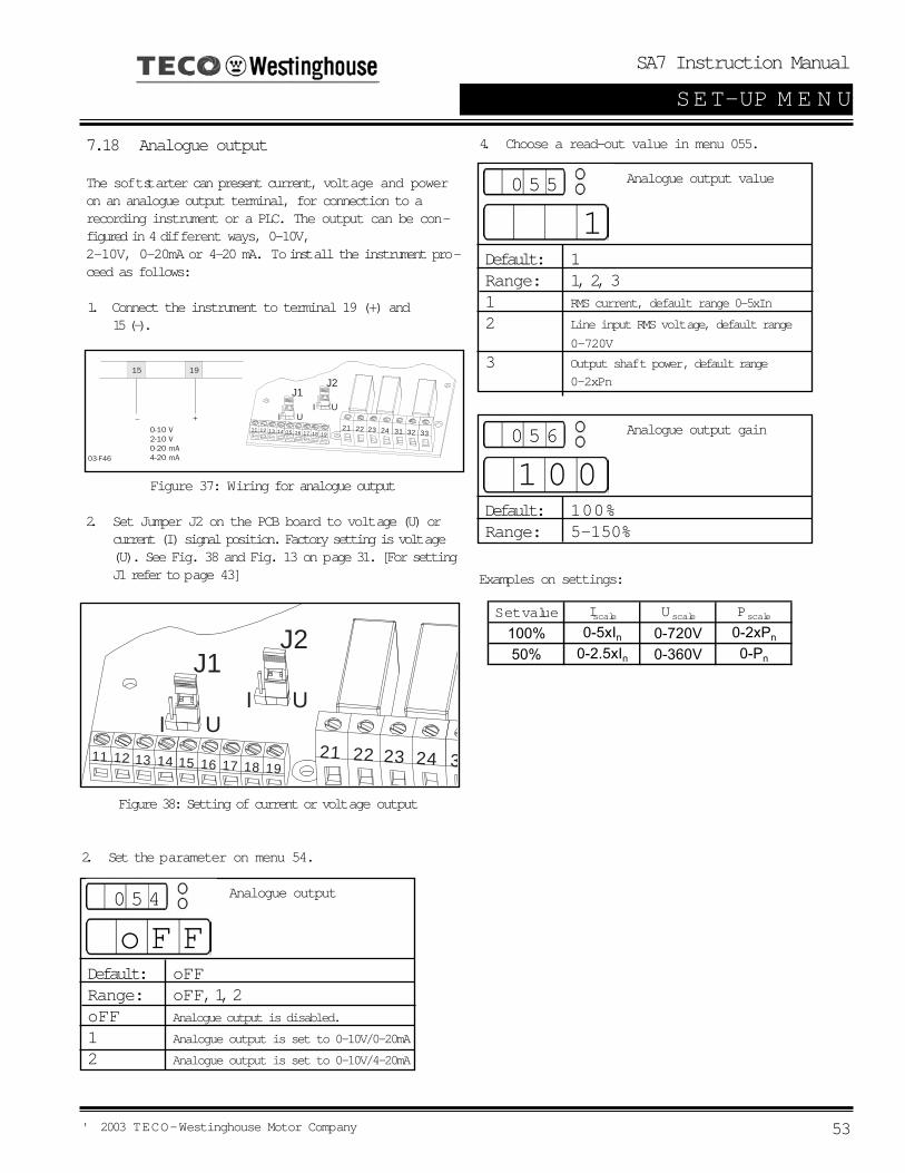
SA7 Instruction Manual
' 2003 TECO-Westinghouse Motor Company 53
SET-UP M E N U
7.18 Analogue output
The soft starter can present current, voltage and poweron an analogue output terminal, for connection to arecording instrument or a PLC. The output can be con-figured in 4 different ways, 0-10V, 2-10V, 0-20mA or 4-20 mA. To install the instrument pro-ceed as follows:
1. Connect the instrument to terminal 19 (+) and 15 (-).
12 1622
I U
J1J2
I U
11 13 14 15 17 18 1921 23 24 31 32 33
Figure 37: Wiring for analogue output
2. Set Jumper J2 on the PCB board to voltage (U) or current (I) signal position. Factory setting is voltage (U). See Fig. 38 and Fig. 13 on page 31. [For setting J1 refer to page 43]
Figure 38: Setting of current or voltage output
2. Set the parameter on menu 54.
12 1622
I U
J1J2
I U
11 13 14 15 17 18 1921 23 24 31
Analogue output
Default: oFFRange: oFF, 1, 2oFF Analogue output is disabled.
1 Analogue output is set to 0-10V/0-20mA
2 Analogue output is set to 0-10V/4-20mA
0 5 4
o F F
4. Choose a read-out value in menu 055.
Analogue output value
Default: 1Range: 1, 2, 31 RMS current, default range 0-5xIn
2 Line input RMS voltage, default range
0-720V
3 Output shaft power, default range
0-2xPn
0 5 5
1
Analogue output gain
Default: 100%Range: 5-150%
0 5 6
1 0 0
Examples on settings:
Set value Iscale Uscale Pscale
100% 0-5xIn 0-720V 0-2xPn
50% 0-2.5xIn 0-360V 0-Pn

SA7 Instruction Manual
' 2003 TECO-Westinghouse Motor Company54
SET-UP M E N U
12 1622
I U
J1J2
I U
11 13 14 15 17 18 1921 23 24 31 32 33Open
Closed
12 1622
I U
J1J2
I U
11 13 14 15 17 18 1921 23 24 31 32 33
7.19 Digital input selectionThe analogue input can be used as a digital input. Thisis programmed in Menu 57. There are 4 different func-tions: Rotation sensor input for braking functions. See
§ 7.14, page 47. Slow speed external controlled. See § 7.15.1,
page 49. Jog functions forward or reverse enabled.
See § 7.25, page 62.
Fig. 39 shows how to set the input for voltage or currentcontrol, with jumper J1 the control board. The default
setting for J1 is voltage control.Figure 39: Setting of J1 for current or voltage control
Fig. 39 shows a wiring example for the analogue input
as it is used for digital input.Figure 40: Wiring for slow speed external input
NOTE! If the Main Function Analogue control is pro-gram-med (see § 7.8, page 43) the analogue inputcan not be used for digital signal input. The menu 57
Digital input selection
Default: oFFRange: oFF, 1-4oFF No digital input control
1 Rotation sensor for brake functions
2 Slow speed function
3 Jog forward command
4 Job reverse command
0 5 7
o F F
Digital input pulses
Default: 1Range: 1-100If Menu 57=1.A positive or negative edge at analogue input from arotation sensor will give a signal to stop the brakingvoltage.If Menu 57=2.The number of edges to be ignored by the slow speedinput, before a start or stop is executed at slow speed.
0 5 8
1
is then automatically set to OFF.NOTE! Jog forward, reverse has to be enabled,
see § 7.25, page 62.
Depending on the selection made in menu 57, menu 58is used to program the number of the edges. The edgescan be generated by an external sensor (photo cell,

SA7 Instruction Manual
' 2003 TECO-Westinghouse Motor Company 55
SET-UP M E N U
7.20 Parameter Set
Parameter Set, an important function which can behandy when using one soft starter to switch in and startdifferent motors, or working under variable load condi-tions. For example; starting and stopping conveyor beltswith different weight on the goods from time to time.For sets of parameters can be controlled either from thekeyboard, the external control inputs or the serial inter-face (option). Up to 51 different parameters can be setfor each Parameter Set.
Parameter Set 2
Parameter Set 3
Parameter Set 4
Common for all parameter set007, 008, 046, 051, 052, 061, 071, 072,088, 089, 105, 111, 112, 113, 114, 199, 206
001, 002, 003, 004, 006,011, 012, 013, 014, 016,017, 020, 021, 022, 023,024, 025, 030, 031, 032,033, 034, 035, 036, 037,038, 039, 040, 041, 042,043, 044, 045, 055, 056,057, 058, 074, 075, 081,082, 083, 084, 085, 086,091, 092, 093, 094, 095,096, 097, 098, 099, 101,102, 103, 104
Figure 41: Parameter overview
When Parameter set in menu 061 is set to 0 (externalselection), only parameters in menu 006 (Control mode)and 061 (Parameter set) can be changed. All otherparameters are not allowed to change. It is possible to change parameter set at stop and at fullvoltage running.
Parameter set
Default: 1Range: 0, 1, 2, 3, 40 Parameter set are selected by the
external input 16 and 17 (see below.)
1, 2, 3, 4 Selection of parameter set 1-4
0 6 1
1
12 1622
I U
J1J2
I U
11 13 14 15 17 18 1921 23 24 31 32 33
Figure 42: Connection of external control inputs
Param eter Set PS1 (16-18) PS2 (17-18)1 Open Open2 Closed Open3 Open Closed4 Closed Closed

SA7 Instruction Manual
' 2003 TECO-Westinghouse Motor Company56
SET-UP M E N U
Motor PTC input
Default: noRange: no, YESno Motor PTC input is disabled.
YES Motor PTC input is activated:
- Connect the PTC to temrinals 69 and 70, see table 9, page 34 and § Fig. 18, page 36.
- A too hot motor will give an F2 alarm. The alarm can only be reset aftercooling down of the motor.
0 7 1
n o
Internal motor thermal pro-tection
Default: 10Range: oFF, 2-40 secoFF Internal motor protection is disabled.
2-40 Selection of the thermal curve
according to Fig. 43- Check that menu 042 is set to the proper motor current (see § 7.16, page 51).
- If the current exceeds the 100% level an F2 alarm is activated.
- The motor model thermal capacity must cool down to 95% before reset can be accepted.
- Used thermal capacity in menu 073 in § 7.21, page 57.
0 7 2
1 0
Figure 43: The thermal curve
7.21 Motor protection, overload (F2 alarm)
In many cases it is convenient to have a completestarter. The soft starter have a possibility to use either aninput PTC signal from the motor, an internal thermalmodel of the motor for thermal protection or both togeth-er at the same time. Slight overload for long time andseveral overloads of short duration will be detected withboth methods.
NOTE! Open terminals will give an F2 alarmimmediately. Make sure the PTC is always connected or the terminals are shorted.
NOTE! The internal motor thermal protection will still generate an alarm if it is not selected oFF.
NOTE! If Bypass is used check that the current trans-formers are placed and connectedcorrectly.
CAUTION! Used thermal capacity is set to 0if the control board loses its supply (termi-nal 01 and 02). This means that the internalthermal model starts with a cold motor,
which perhaps in reality is not the case. This meansthat the motor can be overheated.
!
Overload time sec
Current (x I )nom

SA7 Instruction Manual
' 2003 TECO-Westinghouse Motor Company 57
SET-UP M E N U
Used thermal capacity
Default: -Range: 0-150%Read-out of the used thermal capacity. If menu 072Internal motor thermal protection is selected oFF, thecapacity is shown as if the default class 10 wasselected.
0 7 3
0Voltage unbalance alarm
Default: 10Range: 2-25% UnInsert limit in % of nominal motor voltage. Max unbal-ance in voltage between the 3 input phases is com-pared with the selected value. This is a category 2alarm.
0 8 1
1 0
Over voltage alarm
Default: 115Range: 100-150% UnInsert limit in % of nominal motor voltage. Max voltageof the 3 input phases is compared with the selectedvalue. This is a category 2 alarm.
0 8 3
1 1 5
Response delay over volt-age alarm
Default: oFFRange: oFF, 1-60 secoFF Overvoltage alarm is disabled
0 8 4
o F F
Starts per hour limitation
Default: oFFRange: oFF, 1-99 / houroFF Starts per hour limitation is disabled.
1-99 Sets the start per hour limitation alarm.
If the selected number is exceeded, alarm F11 occurs.
0 7 4
o F F
Locked rotor alarm
Default: oFFRange: oFF, 1.0-10.0 secoFF Locked rotor alarm is disabled.
1.0-10.0 An F5 alarm is given when the rotor
locks. The alarm is active during start-ing
0 7 5
o F F
Response delay voltageunbalance alarm
Default: oFFRange: oFF, 1-60 secoFF Unbalance voltage alarm is disabled
1-60 Set the response delay time for
unbalanced voltage alarm F8.
0 8 2
o F F
7.22 Mains protection
1-60 Set the response delay time for over voltage alarm F9.

SA7 Instruction Manual
' 2003 TECO-Westinghouse Motor Company58
SET-UP M E N U
Under voltage alarm
Default: 85Range: 75-100% UnInsert limit in % of nominal motor voltage. Min voltageof the 3 input phases is compared with the selectedvalue. This is a category 2 alarm.
0 8 5
o F F
Phase sequence
Default: -Range: L123, L321
0 8 7
- - - -
Phase reversal alarm
Default: oFFRange: oFF, onoFF Phase reversal alarm is disabled.
0 8 8
o F F
on Set the phase reversal Alarm.- Switch on the power supply first.The phase sequence is stored as the correct sequence.
- Set the menu 088 to on .- Any reversal of phase sequence will cause alarm F16.
Response delay undervoltage alarm
Default: oFFRange: oFF, 1-60 secoFF Under voltage alarm is disabled
0 8 6
o F F
1-60 Set the response delay time for under voltage alarm F10.
Auto set power limits
Default: noRange: no, YESno Auto set is disabled.
0 8 9
n o
YES Auto set is activated if ENTER is
Output shaftpower in %.
Default: -Range: 0-200%Measured output shaftpower in % of nominal motor
power.
0 9 0
n oL123 is the direct phase sequence.L321 is the reverse phase sequence.
7.23 Application protection (load monitor)
7.23.1 Load monitor max and min/protection
(F6 and F7 alarms)AS6 has a built in load monitor based on the outputshaftpower. This is a unique and important functionwhich enables protection of machines and processesdriven by the motor connected to the soft starter. Both aMin and Max limit is possible to select.In combination with the pre-alarm function, see § 7.23.2, page 59, this create a powerful protection. Anauto set function is also included for an automatic settingof the alarm limits. A start-up delay time can be selectedto avoid undesired alarms at start-up, see Fig. 44 onpage 61.
NOTE! The load monitor alarms are all disabledduring a stop ramp.
NOTE! The actual phase sequence can beviewed in menu 87.
NOTE! System must be in full voltage runningbefore
an auto set is permitted.
The actual power is regarded as 1.00xPact.The set levels are:Power max alarm limit [092]: 1.15xP actualPower max pre-alarm limit [094]: 1.10xP actualPower min pre-alarm limit [096]: 0.90xP actualPower min alarm limit [098]: 0.85xP actual
A successful auto set shows a message Set for 3 s and

SA7 Instruction Manual
' 2003 TECO-Westinghouse Motor Company 59
SET-UP M E N U
Start delay power limits
Default: 10 secRange: 1-250 sec
0 9 1
1 0
From start command during selected delay time, allpower load monitor alarms and pre-alarms aredisabled.
Max power alarm limit
Default: 115Range: 5-200% Pn
0 9 2
1 1 5
Insert limit in % of nominal motor power. The actualpower in % of nominal motor power, could be readout in menu 090. If output shaft power exceedsselected limit, an F6-alarm occurs after the responsedelay time. The Auto set function in menu 089, affectthis limit even if the alarm is set oFF in menu 093.This is a category 1 alarm.
Max power pre-alarm limit
Default: 110Range: 5-200% Pn
0 9 4
1 1 0
Insert limit in % of nominal motor power. The actualpower in % of nominal motor power, could be readout in menu 090. If output shaft power exceedsselected limit, a pre-alarm occurs after the responsedelay time. The Auto set function in menu 089, affectselected limit even if the pre-alarm is set oFF inmenu 095.
Response delay maxalarm
Default: oFFRange: oFF, 0.1-25.0 secoFF Max Alarm is disabled.
0.1-25.0 Sets the response delay of the Max
Alarm level.
0 9 3
o F F
Max pre-alarm responsedelay
Default: oFFRange: oFF, 0.1-25.0 secoFF Max Pre-Alarm is disabled.
0.1-25.0 Sets the response delay of the Max
Pre-Alarm level.
0 9 5
o F F
7.23.2 Pre-alarmIt could be useful to know if the load is changing towardsa load alarm limit. It is possible to insert both a Max andMin pre-alarm limit based on the motor output shaftpower. If the load exceeds one of these limits, a pre-alarm condition occurs. It should be noted that it is not normal alarms. They willnot be inserted in the alarm list, not activating the alarmrelay output, not displayed on the display and they willnot stop operation. But it is possible to activate relay K1or K2 if a pre-alarm condition occurs. To have pre-alarmstatus on any of these relays, select value 3 in menu051 or 052 (see § 7.17, page 52).A start-up delay time can be selected in menu 091 toavoid undesired pre-alarms at start-up. Note that thistime is also shared with power Max and Min alarms.
NOTE! The pre-alarm status is always available on the serial communication.

SA7 Instruction Manual
' 2003 TECO-Westinghouse Motor Company60
SET-UP M E N U
Min power alarm limit
Default: 85Range: 5-200% Pn
0 9 8
8 5
Insert limit in % of nominal motor power. The actualpower in % of nominal motor power, could be readout in menu 090. If output shaft power goes belowselected limit, an F7-alarm occurs after the responsedelay time. The Auto set function in menu 089, affectthis limit if the alarm is set oFF in menu 099. This iscategory 1 alarm.
Min power pre-alarm limit
Default: 90%Range: 5-200% Pn
0 9 6
9 0
Insert limit in % of nominal motor power. The actualpower in % of nominal motor power, could be readout in menu 090. If output shaft power goes belowselected limit, a pre-alarm occurs after the responsedelay time. The Auto set function in menu 089, affectselected limit even if the pre-alarm is set oFF inmenu 097.
Min pre-alarm responsedelay
Default: oFFRange: oFF, 0.1-25.0 secoFF Min Pre-Alarm is disabled.
0.1-25.0 Sets the response delay of the Min
Pre-Alarm level. The Pre-alarm is disabled during a stop reamp down.
0 9 7
o F F
Min alarm response delay
Default: oFFRange: oFF, 0.1-25.0 secoFF Min Alarm is disabled.
0.1-25.0 Sets the response delay of the Min
Alarm level. The Min alarm is dis-abled during a stop ramp down.
0 9 9
o F F

SA7 Instruction Manual
' 2003 TECO-Westinghouse Motor Company 61
SET-UP M E N U
92 M
ax A
larm
(11
5%)
94 M
ax P
re-A
larm
(11
0%)
100%
Def
ault:
PN
OM o
rA
utos
et: P
MO
ME
NTA
RY
96 M
in P
re-A
larm
(90
%)
98 M
in A
larm
(85
%)
Max
Ala
rm
Max
Pre
-Ala
rm
Min
Ala
rm
Min
Ala
rm
93 R
espo
nse
Del
ay (
1s)
95 R
espo
nse
Del
ay (
1s)
91 R
espo
nse
Del
ay (
10s)
97 R
espo
nse
Del
ay (
1s)
99 R
espo
nse
Del
ay (
1s)
93 R
espo
nse
Del
ay (
1s)
95 R
espo
nse
Del
ay (
1s)
Sta
rt r
amp
Un
der
load
sit
uat
ion
Ove
rlo
ad s
itu
atio
n
Figure 44: Load monitor alarm functions

SA7 Instruction Manual
' 2003 TECO-Westinghouse Motor Company62
SET-UP M E N U
7.24 Resume alarms
7.24.1 Phase input failure F1 Multiple phase failure.Shorter failure than 100ms is ignored. If failure durationtime is between 100 ms and 2 s, operation is temporarystopped and a soft start is made if the failure disappearsbefore 2 s. If failure duration time is longer than 2 s, anF1 alarm is given in cat. 2. Single phase failure.During start up (acceleration) the behaviour is like multi-ple phase failure below. When full voltage running thereis a possibility to select the behavior.
Run at single phase loss
Default: noRange: no, YESno Soft starter trips if a single phase loss is detect
ed. Alarm F1 (category 2) will appear after 2 s.Soft starter continues to run after a single phase loss.
YES - Alarm F1 appears after 2 sec.- If the loose phase is reconnect the alarm is reset automatically.
- If running on 2 phases, a stop command will give a Direct on line stop (freewheel).
1 0 1
n o
7.24.2 Run at current limit time-out F4In modes Current limit at start and Voltage ramp withcurrent limit at start an alarm is activated if still operatingat current limit level when selected ramp time exceeds. Ifan alarm occurs there is a possibility to select thebehaviour.
Run at current limit time-out
Default: noRange: no, YESno Soft starter trips if the current limit time-out is
exceeded. Alarm F4 (category 2) appears.Soft starter continues to run after the current limit time-out has exceeded:
YES - Alarm F4 appears- The current is no longer controlled and the soft starters ramps up to full voltage with a 6s ramp time.
- Reset the alarm with either ENTER/RESETkey or by giving a stop command.
1 0 2
n o
7.25 Slow speed with JOG
Slow speed with "JOG" is possible from the "JOG" keys,but also from terminals, see menu 57 page 54 and serialcomm. The "JOG" is ignored if the soft starter is running.The slow speed "JOG" function has to be enabled forboth forward and reverse directions in menus 103 and104, see below.
NOTE! The enable functions is for all control modes.
JOG forward enabled
Default: oFFRange: oFF, onoFF JOG forward disabled.
1 0 3
o F F
JOG reverse enabled
Default: oFFRange: oFF, onoFF JOG reverse disabled
1 0 4
o F F
JOG JOG
Figure 45: The 2 Jog keys

SA7 Instruction Manual
' 2003 TECO-Westinghouse Motor Company 63
SET-UP M E N U
7.26 Automatic return menu
Often it is desirable to have a specific menu on the dis-play during operation, i.e. RMS current or power con-sumption. The Automatic return menu function gives thepossibility to select any menu in the menu system.The menu selected will come up on the display after 60sec. if no keyboard activity. The alarm messages (F1-F16) have a priority over menu 105 (as they have for allmenus).
Automatic return menu
Default: oFFRange: oFF, 1-999
1 0 5
o F F
1-999 Pressing + / - will lead through the menu system.
Serial comm unit address
Default: 1Range: 1-247
1 1 1
1
This parameter will select the unit address.
Serial comm baudrate
Default: 9.6Range: 2.4, 4.8, 9.6, 19.2,38.4 kBaud
1 1 2
9.6
This parameter will select the baudrate.
Serial comm parity
Default: 0Range: 0.1
1 1 3
0
This parameter will select the parity.0 No parity.1 Even parity.
Serial comm contact inter-rupted
Default: 1Range: oFF, 1, 2
1 1 4
1
This parameter will control the bahavior in the softstarter when the serial comm. is interrupted.
oFF No alarm and continue operation.1 Alarm and stop operation.2 Alarm and continue operation.
7.27 Communication option, related Parameters
The following parameters have to be set-up:- Unit address.- Baud rate.- Parity- Behaviour when contact broken.
Setting up the communication parameter must be madein local Keyboard control mode. See § 7.2, page 39.
Serial comm. broken alarmIf control mode is Serial comm. control and no contactis established or contact is broken the Soft starter con-sider the contact to be broken after 15 sec, the softstarter can act in three different ways:
1 Continue without any action at all.2 Stop and alarm after 15 sec.3 Continue and alarm after 15 sec.
If an alarm occurs, it is automatically reset if the com-munication is re-established. It is also possible to resetthe alarm from the soft starter keyboard.

SA7 Instruction Manual
' 2003 TECO-Westinghouse Motor Company64
SET-UP M E N U
RMS current
Default: -Range: 0.0 - 9999Amp
2 0 1
0.0
Read-out of the RMs motor current.
7.28 Reset to factory setting [199]
When selecting reset to factory settings: All parameters in all parameter sets will have default
factory settings. Menu 001 will appear on the display. Note that the alarm list, the power consumption and
the operation time will not have default settings.
Reset to factory settings
Default: noRange: no, YESno No reset.
YES Reset all functions to the factory defaults incl. all 4 Parameter Sets.
1 9 9
n o
NOTE! Reset to factory settings is not allowed at run.
7.29 View operation
GeneralThe soft start includes as standard numerous meteringfunctions which eliminate the need of additional trans-ducers and meters.
Measured values- Current RMS 3-phase current and per phase- Voltage RMS 3-phase voltage and per phase- Output shaft power /torque HP/ft.lb.- Power factor- Power consumption in kWh- Operation time in hours
Viewing of the measured valuesAfter setting motor data and extended functions one canset menu 008 in oFF and will then automatically move tomenu 201, the first menu viewing the measured valuesand thus eliminate to scroll through menu 011 to menu199.
RMS main voltage
Default: -Range: 0 - 720V
2 0 2
0.0
The RMS input main voltage.
Output motor shaftpower
Default: -Range: -9999 - +9999HP
2 0 3
0.0
Viewing will show negative value if generatormode.
Power factor
Default: -Range: 0.00-1
2 0 4
0.0
Viewing the actual power factor.
Total power consumption
Default: -Range: 0.000-2000MWh
2 0 5
0.0 0 0
View the total power consumption.
NOTE! The power factor viewing will not work at bypass even if the current transformers are mounted outside the soft start.

SA7 Instruction Manual
' 2003 TECO-Westinghouse Motor Company 65
SET-UP M E N U
Reset of powerconsumption
Default: noRange: no, YESno No reset of power consumption.
YES Reset power consumption in menu 205 to 0.000.
2 0 6
n o
Motor shaft torque
Default: -Range: -9999 - +9999ft.lb.
2 0 7
0.0
Viewing will show negative value of generatormode.
RMS current in phase L1
Default: -Range: 0.0 - 9999Amp
2 1 1
0.0
View the current in phase L1.
RMS current in phase L2
Default: -Range: 0.0 - 9999Amp
2 1 2
0.0
View the current in phase L2.
RMS current in phase L3
Default: -Range: 0.0 - 9999Amp
2 1 3
0.0
View the current in phase L3.
Main voltage L1-L2
Default: -Range: 0-720V
2 1 4
0
View main voltage L1-L2.
Main voltage L1-L3
Default: -Range: 0-720V
2 1 5
0
View main voltage L1-L3.
Main voltage L2-L3
Default: -Range: 0-720V
2 1 6
0
View main voltage L2-L3.
Operation time
Default: -Range: Hours
2 0 8
0.0
Operation tme is calculated when the soft starteris in RUN mode. After 9999 hours the displaywill show two values.Example: 12467 hours shows 1 1 sec
2467 5 sec

SA7 Instruction Manual
' 2003 TECO-Westinghouse Motor Company66
SET-UP M E N U
Alarm
Default: -Range: F1-F6
9 0 1
F 1
View actual alarm.
7.30 Keyboard lock
The keyboard can be locked to prohibit operation andparameter setting by an unauthorised. Lock keyboard bypressing both keys "NEXT g" and "ENTER8 " for at least2 sec. The message - Loc will display when locked. Tounlock keyboard press the same 2 keys "NEXT g" and"ENTER8 " for at least 2 sec. The message unlo willdisplay when unlocked.In locked mode it is possible to view all parameters andread-out, but it is forbidden to set parameters and tooperate the soft starter from the keyboard.The message -Loc will display if trying to set a parame-ter or operate the soft starter in locked mode.The key lock status can be read out in menu 221.
Locked keyboard info
Default: noRange: no, YESno Keyboard is not locked.
YES Keyboard is locked.
2 2 1
n o
7.31 Alarm listThe alarm list is generated automatically. It shows thelatest 15 alarms (F1 - F16). The alarm list can be usefulwhen tracing a failure in the soft starter or its control cir-cuit. Press key NEXT g or PREV f to reach the alarmlist in menus 901-915 (menu 007 has to be ON).

SA7 Instruction Manual
' 2003 TECO-Westinghouse Motor Company 67
PROTECTION & ALARM
8.0 PROTECTION AND ALARMThe soft starter is equipped with a protection system for the motor, the machine and for the soft starter itself.Three categories of alarm are available:
Category 1Alarm that stops the motor and needs a separate reset before a new start can be accepted.
Category 2Alarm that stops the motor and accepts a new start command without any separate reset.
Category 3Alarm that continues to run the motor.
All alarm, except pre-alarm, will activate the alarm relay output K3, flash a red fault number on the display and it willalso be placed in the alarm list. As long as the alarm is active, the display is locked in the alarm indication.The relay output K3 can be used in the control circuit for actions needed when alarm occurs.If more than one alarm is active, it is the last alarm that is presented on the display.
8.1 Alarm description
8.1.1 Alarm with stop and requiring a separate resetOperation will stop for a category 1 alarm. A separate reset is needed before a new start command is accepted. It ispossible to reset from keyboard (pushing "ENTER/RESET") regardless of selected control mode. It is also possibleto reset the alarm from the actual control mode (i.e. if control mode is serial communication, a reset is possible to dofrom serial communication).A reset is accepted first when the alarm source goes back to normal.When a reset is made, the alarm relay output K3 is deactivated, the alarm indication on the display disappear andthe original menu shows.After a reset is made the system is ready for a new start command.
8.1.2 Alarm with stop and requiring only a new start commandOperation will stop for a category 2 alarm. A restart can be done and at the same time the alarm relay output K3 isdeactivated, the alarm indication on the display disappear and the original menu shows.It is still possible to reset the alarm in the same way as for category 1 alarms (see 8.1.1), if a start is not required atthe time.
8.1.3 Alarm with continue run Operation will continue run for a category 3 alarm. Some different reset behaviour is possible (see remarks for thespecific alarms in § 8.2, page 68). Automatic reset when the alarm source goes back to normal. Automatic reset when a stop command is given. Manual reset during run.
When the reset occurs, the alarm relay output K3 is deactivated, the alarm indication on the display disappear andthe original menu shows.

SA7 Instruction Manual
' 2003 TECO-Westinghouse Motor Company68
PROTECTION & ALARM
Display indication
Protective function
Alarm category Rem ark
Cat 3. Run with auto reset.Single phase failure when full voltage running if menu 101 'Run at phase loss' = YES. If the fault phase comes back, an automatic reset is made.
Cat 2. Stop with reset in start.
Multiple phase failure or single phase failure when not full voltage running or if menu 101 'Run at phase loss' = no.
F2Motor protection, overload.
Cat 1. Stop with manual reset.
If menu 071 'Motor PTC input' = YES, cool down the motor. If menu 071 'Motor PTC input' = no, the internal model has to 'cool' down.
F3Soft start overheated
Cat 1. Stop with manual reset.
If not cooled down, a reset will not be accepted.
If menu 102 'Run at current limite time-out' = no. Cat 2. Stop with reset in start.
The current limit start is not completed.
If menu 102 'Run at current limite time-out' = YES. Cat 3. Run with manual reset.
When start time expired, a 6 sec ramp is used to reach full voltage, without control of the current. Reset the alarm with either a manual reset or a stop command.
F5 Locked rotor. Cat 1. Stop with manual reset.
Motor and/or machine protection.
F6Above max power limit.
Cat 1. Stop with manual reset.
Machine protection.
F7Below min power limit.
Cat 1. Stop with manual reset.
Machine protection.
F8 Voltage unbalance. Cat 2. Stop with reset in start.
Motor protection.
F9 Over voltage Cat 2. Stop with reset in start.
Motor protection.
F10 Under voltage Cat 2. Stop with reset in start.
Motor protection.
F11Starts / hour exceeded.
Cat 2. Stop with reset in start.
Motor and/or machine protection.
F12 Shorted thyristorCat 3. Run with manual reset.
When stop command comes, the stop will be a 'Direct On Line' stop, and the soft starter will be resetted. After this fault it is possible to start only in 'Direct On Line' mode. One or more thyristors probably damaged.
F13 Open thyristor Cat 1. Stop with manual reset.
One or more thyristors probably damaged.
F14Motor terminal open.
Cat 1. Stop with manual reset.
Motor not correctly connected.
If menu 114 Serial comm. Contact broken = 1. Cat 2. Stop with reset in start.
Serial communication broken will stop operation. Run from keyboard if necessary.
If menu 114 Serial comm. Contact broken = 2. Cat 3. Run with auto reset.
Serial communication broken will not stop operation. Run from keyboard if necessary.
F16Phase reversal alarm.
Cat 1. Stop with manual reset.
Incorrect phase order on main voltage input.
F15Serial communication broken
Phase input failureF1
F4
Full speed not reached at set current limit and start time.
8.2 Alarm overview

SA7 Instruction Manual
' 2003 TECO-Westinghouse Motor Company 69
TROUBLESHOOTING
9.1 Fault, cause and solution9.0 TROUBLESHOOTING
Observation Fault Indication Cause SolutionThe display is not
illum inatedNone No control voltage. Switch on the control voltage.
Fuse detective Renew the fuse.No mains supply. Switch the main supply on.
F2(Motor protection, overload)
Perhaps PTC connection. Perhaps incorrect nominal motor current inserted (menu 042).
Check the PTC input if PTC protection is used.If internal protection is used, perhaps another class could be used (menu 072). Cool down the motor and make a reset.
F3(Soft start overheated)
Abient temperature too high. Soft starter duty cycle exceeded.Perhaps fan failure.
Check ventilation of cabinet.Check the size of the cabinet.Clean the cooling fans.If the fan(s) is not working correctly, contact your local distributor.
F4(Full speed not reached at set current limit and start time)
Current limit parameters are perhaps not matched to the load and motor.
Increase the starting time and/or the current limit level.
F5(Locked rotor)
Something stuck in the machine or perhaps motor bearing failure.
Check the machine and motor bearings. Perhaps the alarm delay time can be set longer (menu 075).
F6(Above max power limit)
Overload Overload. Check the machine. Perhaps the alarm delay time can be set longer (menu 093).
F7(Below min power limit)
Underload Under load. Check the machine. Perhaps the alarm delay time can be set longer (menu 099).
F8(Voltage unbalance)
Main supply voltage unbalance.
Check mains supply.
F9(Over voltage)
Main supply over voltage. Check mains supply.
F10(Under voltage)
Main supply under voltage. Check mains supply.
F11(Starts / hour exceeded)
Number of starts exceeded according to meny 074.
Wait and make a new start. Perhaps the number of starts / hour could be increased in menu 074.
F13(Open thyristor) Perhaps a damaged thyristor. Make a reset and a restart. If the same alarm appears
immediately, contact Saftronics Technical Support.
F14(Motor terminal open)
Open motor contact, cable or motor winding.
If the fault is not found, reset the alarm and inspect the alarm list. If alarm F12 is found, a thyristor is probably shorted.Make a restart. If alarm F14 appears immediately, contact Saftronics Technical Support.
F1(Phase input failure)
The m otor does not
run

SA7 Instruction Manual
' 2003 TECO-Westinghouse Motor Company70
TROUBLESHOOTING
Observation Fault Indication Cause Solution
F15(Serial Communication broken)
Serial communication broken.
Make a reset and try to establish contact. Check contacts, cables and option boards.Verify- System address (menu 111).- Baudrate (menu 113).- Parity (menu 113).If the fault is not found run the motor with keyboard control if urgent, see also manual f
F16(Phase reversal)
Incorrect phase sequence on main supply. Switch L2 and L3 input phases.
- - - -
Start command comes perhaps from incorrect control source. (I.e. start from keyboard when remote control is selected.
Give start command from correct source (menu 006).
-Loc System in keyboard lock. Unlock keyboard by pressing the keys 'NEXT' and 'ENTER' for at least 3 sec.
F1(Phase input failure)
Failure in one phase. Perhaps fuse defective.
Check fuses and mains supply. Deslect 'Run at single phase input failure' in menu 101, if stop is desired at single phase loss.
F4(Full speed not reached at set current limit and start time)
Current limit parameters are perhaps not matched to the load and motor.
Increase the starting time and / or the current limit level. Deselct 'Run at current limit time-out' in menu 102, if stop is desired at current limit time-out.
Perhaps a damaged thyristor.
When stop command is given, a free wheel stop is made. Make a reset and a restart. If alarm F14 appears immediately, contact Saftronics Technical Support.
Bypass contactor is used but meny 032 'Bypass' is not set to "on".
Set meny 032 'Bypass' to "on".
F15(Serial Communication broken)
Serial communication broken.
Make a reset and try to establish contact. Check contacts, cables and option boards.Verify- System address (menu 111).- Baudrate (menu 113).- Parity (menu 113).If the fault is not found run the motor with keyboard control if urgent, see also manual f
The m otor does not run.
F12(Shorted thyristor)
The m otor is running but an alarm is given.

SA7 Instruction Manual
' 2003 TECO-Westinghouse Motor Company 71
TROUBLESHOOTING
Observation Fault Indication Cause Solution
If 'Torque control' or "Pump control' is selected, it is necessary to input motor data into the systems.
Input nominal motor data in menus 041-046. Select the proper load characteristic in menu 025. Select a correct initial and end torque at start in menus 016 and 017. If 'Bypass' is selected, check that the current transformers are correctly connected.
Starting time too short. Increase starting time.
Starting voltage incorrectly set. Adjust starting voltage.
Motor too small in relation to rated current of soft starter.
Use a smaller model of the soft starter.
Motor too large in relation to load of soft starter.
Use larger model of soft starter.
Readjust the start ramp.Select the durrent limit function.
Ramp times not set correctly. Readjust the start and/or stop ramp time.
Motor too large or too small in relation to load.
Change to another motor size.
The m onitor
function does not
work.No alarm or pre-alarm.
It is necessary to input nominal motor data for this function. Incorrect alarm levels.
Input nominal motor data in menus 041-046. Adjust alarm levels in menus 091-099. If 'Bypass' is selected, check that the current transformers are correctly connected.
Unexplainable
alarm .FF5, F6, F7, F8, F9, F10 Alarm delay tome is too short. Adjust the response delay times for the alarms in menus
075, 082, 084, 086, 093, and 099.
F2(Motor protection, overload)
PTC input terminal could be open.Motor could still be too warm. If internal motor protection is used, the cooling in the internal model take some time.
PTC input terminal should be short circuit if not used. Wait until motor PTC gives an OK (not overheated) signal. Wait until the internal cooling is done. Try to reset the alarm after a while.
F3(Soft start overheated)
Ambient temperature too high. Perhaps fan failure.
Check that cables from power part are connected in terminals 073, 074, 071 and 072. MSF-071 to MSF-145 should have a short circuit betweem 071 and 072. Check also that the fan(s) is rotating.
If the menu number is one of 020 - 025, only one can be selected, i.e. only one main mode is possible at a time.
Deselect the other main mode before selecting the new one.
If menu 061, 'Parameter set' is set to "0", the system is in a remote parameter selection mode. It is now impossible to change most of the parameters.
Set the menu 061, 'Parameter set' to a value between "1" - "4" and then it is possible to change any parameter.
During acceleration, deceleration, slow speed, DC brake and power factor control mode, it is impossible to change parameters.
Set parameters during stop or full voltage running.
If control source is serial comm., it is impossible to change parameters from keyboard and vice versa.
Change parameters from the actual control source.
Some menus include only read out values and not parameters.
Read-out values can not be altered. In table 13, page 35, read-out menus has '---' in the factory setting column.
-Loc Keyboard is locked. Unlock keyboard by pressing thekeys 'NEXT' and 'ENTER' for at least 3 sec.
Starting voltage not set correctly.
Starting or stopping time too long, soft does not not work.
The m otor jerks
etc.
The system seem s
locked in an alarm .
- - - -Param eter will not
be accepted.
When starting, motor reaches full speed but it jerks or vibrates.

SA7 Instruction Manual
' 2003 TECO-Westinghouse Motor Company72
MAINTENANCE
10.0 MAINTENANCE
In general the soft starter is maintenance free. There are however some things which should be checked regularly.Especially if the surroundings are dusty the unit should be cleaned regularly.
W ARNING! Do not touch parts inside the enclosure of the unit when the control and motor voltageis switched on.
Regular maintenance
Check that nothing in the soft starter has been damaged by vibration (loose screws or connections).
Check external wiring, connections and control signals. Tighten terminal screws and busbar bolts ifnecessary.
Check that PCB boards, thyristors and cooling fin are free from dust. Clean with compressed air if
necessary. Make sure the PCB boards and thyristors are undamaged.
Check for signs of overheating (changes in colour on PCB boards, oxidation of solder points etc.). Check that the temperature is within permissible limits.
Check that the cooling fan/s permit free air flow. Clean any external air filters if necessary.
In the event of fault or if a fault cannot be cured by using the fault-tracing table in chapter 9. page 69.
!

SA7 Instruction Manual
' 2003 TECO-Westinghouse Motor Company 73
OPTIONS
11.0 OPTIONSThe following option are available. Please contact your supplier for more detailed information.
11.1 Serial communication
For serial communication the MODBUS RTU(RS232/RS485) option card is available.
11.2 Field bus systems
Various option cards are available for the following bus systems:
PROFIBUS DP Device NET LONWORKS FIP IO INTERBUS-S
Each system has it s own card. The option is deliveredwith an instruction manual containing the all details for theset-up of the card and the protocol for programming.
11.3 External PPU
The external PPU option is used to move the PPU (key-board) from the soft starter to the front of a panel door orcontrol cabinet.The maximum distance between the soft starter and theexternal PPU is 3 m.The option can be factory mounted (01-2138-01) or it canbe built in later (01-2138-00). For both versions instruction/data sheet are available.
Figure 46: Option RS232/485
Figure 47: Option Profibus
(03-F62)
Figure 48: Shows an example of the External PPU after it has been built in

SA7 Instruction Manual
' 2003 TECO-Westinghouse Motor Company74
SET-UP MENU LIST
M enunum ber
Function/Param eter Range Par.setFactorySetting
Value Page
001 Initial voltage at start 25-90% of U 1 - 4 30 38002 Start time ramp 1 1-60 sec 1 - 4 10 38003 Step down voltage at stop 100-40% U 1 - 4 100 38004 Stop time ramp 1 oFF, 2-120 sec 1 - 4 oFF 38005 Current 0.0-9999 Amp ----- ---- 38006 Control mode 1, 2, 3 1 - 4 2 39007 Extended functions & metering oFF, on ----- oFF 40008 Extended functions oFF, on ----- oFF 40
011 Initial voltage start ramp 2 30-90% U 1 - 4 30 40012 Start time ramp 2 oFF, 1-60 sec 1 - 4 oFF 40013 Step down voltage stop ramp 2 100-40% U 1 - 4 40 40014 Stop time ramp 2 oFF, 2-120 sec 1 - 4 oFF 40
016 Initial torque at start 0-250% Tn 1 - 4 10 40017 End torque at start 50-250% Tn 1 - 4 150 41018 End torque at stop 0-100% Tn 1 - 4 0 41020 Voltage ramp with current limit at start oFF, 150-500% In 1 - 4 oFF 41021 Current limit at start oFF, 150-500% In 1 - 4 oFF 42022 Pump control oFF, on 1 - 4 oFF 42023 Remote analogue control oFF, 1, 2 1 - 4 oFF 43024 Full voltage start D.O.L. oFF, on 1 - 4 oFF 43025 Torque control oFF, 1, 2 1 - 4 oFF 44
030 Torque boost active time oFF, 0.1-2.0 sec 1 - 4 oFF 45031 Torque boost current time 300-700% In 1 - 4 300 45032 Bypass oFF, on 1 - 4 oFF 45033 Power Factor Control PFC oFF, on 1 - 4 oFF 47034 Brake active time oFF, 1-120 sec 1 - 4 oFF 47035 Braking strength 100-500% 1 - 4 100 48
036 Braking methods 1, 2 1 - 4 1 48037 Slow speed torque 10-100 1 - 4 10 49038 Slow speed time at start oFF, 1-60 sec 1 - 4 oFF 50039 Slow speed time at stop oFF, 1-60 sec 1 - 4 oFF 50040 DC-Brake at slow speed oFF, 1-60 sec 1 - 4 oFF 50
041 Nominal motor voltage 200-700 V 1 - 4 400 51042 Nominal motor current 25-150% Insoft in Amp 1 - 4 Insoft in Amp 51043 Nominal motor power 25-300% of Pnsoft in kW 1 - 4 Pnsoft in kW 51044 Nominal speed 500-3600 rpm 1 - 4 Nnsoft in rpm 51045 Nominal power factor 0.50-1.00 1 - 4 0.86 51046 Nominal frequency 50, 60 Hz ----- 50 51

SA7 Instruction Manual
' 2003 TECO-Westinghouse Motor Company 75
M enunum ber
Function/Param eter Range Par.setFactorySetting
Value Page
051 Programmable relay K1 1, 2, 3, (4), 5 1 52052 Programmable relay K2 1, 2, 3, 4, 5 ---- 2 52
054 Analogue output oFF, 1, 2 1 - 4 oFF 53055 Analogue output value 1, 2, 3 1 - 4 1 53056 Scaling analogue output 5-150% 1 - 4 100 53057 Digital input selection oFF, 1, 2, 3, 4 1 - 4 oFF 54058 Digital input pulses 1-100 1 - 4 1 54
061 Parameter set 0, 1, 2, 3, 4 ---- 1 55
071 Motor PTC input no, YES ---- no 56072 Internal motor thermal protection class oFF, 2-40 sec ---- 10 56073 Used thermal capacity 0-150% ---- ---- 57074 Starts per hour limitation oFF, 1-99/hour 1 - 4 oFF 57075 Locked rotor alarm oFF, 1.0-10.0 sec 1 - 4 oFF 57
081 Voltage unbalance alarm 2-25% Un 1 - 4 10 57082 Response delay voltage unbalance alarm oFF, 1-60 sec 1 - 4 oFF 57083 Over voltage alarm 100-150% Un 1 - 4 115 57084 Response delay over voltage alarm oFF, 1-60 sec 1 - 4 oFF 57085 Under voltage alarm 75-100% Un 1 - 4 85 58086 Response delay under voltage alarm oFF, 1-60 sec 1 - 4 oFF 58087 Phase sequence L123, L321 ---- ---- 58088 Phase reversal alarm oFF, on ---- oFF 58089 Auto set power limits no, YES ---- no 58090 Output shaft power 0.0-200.0% Pn ---- ---- 58091 Start delay power limits 1-250 sec 1 - 4 10 59092 Max power alarm limit 5-200% Pn 1 - 4 115 59093 Max alarm response delay oFF, 0.1-25.0 sec 1 - 4 oFF 59094 Max power pre-alarm limit 5-200% Pn 1 - 4 110 59095 Max pre-alarm response delay oFF, 0.1-25.0 sec 1 - 4 oFF 59096 Min pre-alarm power limit 5-200% Pn 1 - 4 90 60097 Min pre-alarm response delay oFF, 0.1-25.0 sec 1 - 4 oFF 60098 Min power alarm limit 5-200% Pn 1 - 4 85 60099 Min alarm response delay oFF, 0.1-25.0 sec 1 - 4 oFF 60
101 Run at single phase input failure no, YES 1 - 4 no 62102 Run at current limit time-out no, YES 1 - 4 no 62103 Job forward enable oFF, on 1 - 4 oFF 62104 Job reverse enable oFF, on 1 - 4 oFF 62105 Automatic return menu oFF, 1-999 ---- oFF 63
111 Serial comm. unit address 1-247 ---- 1 63112 Serial comm. baudrate 2.4-38.4 kBaud ---- 9.6 63
SET-UP MENU LIST

SA7 Instruction Manual
' 2003 TECO-Westinghouse Motor Company76
SET-UP MENU LIST
M enunum ber
Function/Param eter Range Par.setFactorySetting
Value Page
113 Serial comm. Parity 0, 1 ---- 0 63114 Serial comm. Contact broken oFF, 1, 2 ---- 1 63
199 Reset to factory settings no, YES ---- no 64
201 Current 0.0-9999 Amp ---- ---- 64202 Line Main Voltage 0-720 V ---- ---- 64203 Output shaft power -9999 - 9999 kW ---- ---- 64204 Power factor 0.00-1.00 ---- ---- 64205 Power consumption 0.000-2000 MWh ---- ---- 64206 Reset power consumption no, YES ---- no 65207 Shaft torque -9999 - 9999 Nm ---- ---- 65208 Operation time Hours ---- ---- 65
211 Current phase L1 0.0 - 9999 Amp ---- ---- 65212 Current phase L2 0.0 - 9999 Amp ---- ---- 65213 Current phase L3 0.0 - 9999 Amp ---- ---- 65214 Line main voltage L1-L2 0 - 720 V ---- ---- 65215 Line main voltage L1-L3 0 - 720 V ---- ---- 65216 Line main voltage L2-L3 0 - 720 V ---- ---- 65
221 Locked keyboard info no, YES ---- no 66
901 Alarm list, Latest error F1 - F16 ---- ---- 66
Explanation of units:
U Input line voltageUn Nominal motor voltage.In Nominal motor current.Pn Nominal motor power.Nn Nominal motor speed.Tn Nominal shaft torque.Insoft Nominal current soft starter. (SA7 rated current)Pnsoft Nominal power soft starter. (SA7 HP at selected voltage)Nnsoft Nominal speed soft starter.
Calculation shaft torque
NOTE! The six main functions for motor control, menus 020 025, can only be selected one at a time.
Tn
60 x 2 πnN= nP
( (

SA7 Instruction Manual
' 2003 TECO-Westinghouse Motor Company 77
INDEX
Numerics
2-wire start/stop . . . . . . . . . . . . . . . . . . . . . . . . . .39
3-wire start/stop . . . . . . . . . . . . . . . . . . . . . . . . . .39
A
Above max power limit . . . . . . . . . . . . . . . . . . . . .68
Alarm category . . . . . . . . . . . . . . . . . . . . . . . . . . .68
Alarm list . . . . . . . . . . . . . . . . . . . . . . . . . . . . . . .66
Alarm reset . . . . . . . . . . . . . . . . . . . . . . . . . . . . .27
Ambient temperatures . . . . . . . . . . . . . . . . . . . . .23
Analogue control . . . . . . . . . . . . . . . . . . . . . . . . .34
Analogue input . . . . . . . . . . . . . . . . . . . . . . . .34, 43
Analogue output . . . . . . . . . . . . . . . . . . . . . . .34, 53
Analogue output gain . . . . . . . . . . . . . . . . . . . . . .53
Analogue output value . . . . . . . . . . . . . . . . . . . . .53
Auto set power limits . . . . . . . . . . . . . . . . . . . . . .58
automatic reset . . . . . . . . . . . . . . . . . . . . . . . . . . .39
Automatic return menu . . . . . . . . . . . . . . . . . . . . .63
B
Basic parameter setting . . . . . . . . . . . . . . . . . . . .13
Below min power limit . . . . . . . . . . . . . . . . . . . . . .68
Brake method . . . . . . . . . . . . . . . . . . . . . . . . . . . .48
Braking Strenght . . . . . . . . . . . . . . . . . . . . . . . . . .48
Braking time . . . . . . . . . . . . . . . . . . . . . . . . . . . . .47
Busbars . . . . . . . . . . . . . . . . . . . . . . . . . . . . . . . .30
Bypass . . . . . . . . . . . . . . . . . . . . . . . . . . . . . . . . .45
C
Cabinet . . . . . . . . . . . . . . . . . . . . . . . . . . . . . . . .29
Checklist . . . . . . . . . . . . . . . . . . . . . . . . . . . . . . .13
Clickson thermistor . . . . . . . . . . . . . . . . . . . . . . .334
Combination matrix . . . . . . . . . . . . . . . . . . . . . . .22
Complaint . . . . . . . . . . . . . . . . . . . . . . . . . . . . . . . .9
Confirm setting . . . . . . . . . . . . . . . . . . . . . . . . . . .27
Connections . . . . . . . . . . . . . . . . . . . . . . . . . .31, 34
Control mode . . . . . . . . . . . . . . . . . . . . . . . . .28, 39
Control voltage . . . . . . . . . . . . . . . . . . . . . . . . . . .34
Control voltage connection . . . . . . . . . . . . . . . . . .31
Cooling fins . . . . . . . . . . . . . . . . . . . . . . . . . . . . .28
Cos phi . . . . . . . . . . . . . . . . . . . . . . . . . . . . . . . .51
Current . . . . . . . . . . . . . . . . . . . . . . . . . . . . . . . . .64
Current in phase L1 . . . . . . . . . . . . . . . . . . . . . . .65
Current in phase L2 . . . . . . . . . . . . . . . . . . . . . . .65
Current in phase L3 . . . . . . . . . . . . . . . . . . . . . . .65
Current limit . . . . . . . . . . . . . . . . . . . . . . . . . . . . .41
Current limit time-out . . . . . . . . . . . . . . . . . . . . . .62
Current transformer . . . . . . . . . . . . . . . . . . . . . . .46
D
D.O.L start . . . . . . . . . . . . . . . . . . . . . . . . . . . . . .43
DC-brake . . . . . . . . . . . . . . . . . . . . . . . . . . . . . . .47
DC-Brake at slow speed . . . . . . . . . . . . . . . . . . . .50
Decrease value . . . . . . . . . . . . . . . . . . . . . . . . . .27
Decrease value of setting . . . . . . . . . . . . . . . . . . .27
Device connections . . . . . . . . . . . . . . . . . . . . . . .31
Different operation situation . . . . . . . . . . . . . . . . .26
Digital inputs . . . . . . . . . . . . . . . . . . . . . . . . . . . .31
Dimension . . . . . . . . . . . . . . . . . . . . . . . . . . . . . .29
DIN VDE 0100 . . . . . . . . . . . . . . . . . . . . . . . . . . .28
Direct On Line start . . . . . . . . . . . . . . . . . . . . . . .43
Dismantling . . . . . . . . . . . . . . . . . . . . . . . . . . . . . .2
Display next window . . . . . . . . . . . . . . . . . . . . . . .27
Display previous window . . . . . . . . . . . . . . . . . . .27
Dual voltage ramp . . . . . . . . . . . . . . . . . . . . . . . .40
E
Electrical characteristic . . . . . . . . . . . . . . . . . . . . .31
Emergency . . . . . . . . . . . . . . . . . . . . . . . . . . . . . . .2
End torque . . . . . . . . . . . . . . . . . . . . . . . . . . . . . .41
F
Factory settings . . . . . . . . . . . . . . . . . . . . . . . . . .64
Features . . . . . . . . . . . . . . . . . . . . . . . . . . . . . . . .12
Forward/reverse . . . . . . . . . . . . . . . . . . . . . . . . . .36
Free circulation of air . . . . . . . . . . . . . . . . . . . . . .28
frequency . . . . . . . . . . . . . . . . . . . . . . . . . . . . . . .51
Full speed not reached . . . . . . . . . . . . . . . . . . . . .68
Full voltage . . . . . . . . . . . . . . . . . . . . . . . . . . . . . .52
Full voltage start . . . . . . . . . . . . . . . . . . . . . . . . . .43
Function . . . . . . . . . . . . . . . . . . . . . . . . . . . . . . . .75
G
General description . . . . . . . . . . . . . . . . . . . . . . .25
H
Heat dissipation . . . . . . . . . . . . . . . . . . . . . . . . . .24
High ambient temperatures . . . . . . . . . . . . . . . . . .45
I
Increase value . . . . . . . . . . . . . . . . . . . . . . . . . . .27
Increase value of setting . . . . . . . . . . . . . . . . . . . .27
Initial torque . . . . . . . . . . . . . . . . . . . . . . . . . . . . .41
Initial voltage at start ramp 1 . . . . . . . . . . . . . . . . .38
Initial voltage at start ramp 2 . . . . . . . . . . . . . . . . .40
13.0 INDEX

SA7 Instruction Manual
' 2003 TECO-Westinghouse Motor Company78
INDEX
INSPECTION AT DELIVERY . . . . . . . . . . . . . . . . .8
Installation . . . . . . . . . . . . . . . . . . . . . . . . . . . . . .28
Insulation test . . . . . . . . . . . . . . . . . . . . . . . . . . . .24
J
JOG Forward . . . . . . . . . . . . . . . . . . . . . . . . .27, 62
JOG fwd/rev . . . . . . . . . . . . . . . . . . . . . . . . . . . . .27
JOG Reverse . . . . . . . . . . . . . . . . . . . . . . . . .27, 62
Jumper J1 . . . . . . . . . . . . . . . . . . . . . . . . . . . . . .43
Jumper J2 . . . . . . . . . . . . . . . . . . . . . . . . . . . . . .53
K
Keyboard . . . . . . . . . . . . . . . . . . . . . . . . . . . . . . .27
Keyboard lock . . . . . . . . . . . . . . . . . . . . . . . .27, 66
Keys . . . . . . . . . . . . . . . . . . . . . . . . . . . . . . . . . .27
L
LED display . . . . . . . . . . . . . . . . . . . . . . . . . . . . .26
Live circuit components . . . . . . . . . . . . . . . . . . . .28
Load monitor . . . . . . . . . . . . . . . . . . . . . . . . . . . .58
Locked rotor . . . . . . . . . . . . . . . . . . . . . . . . . . . . .68
Low load . . . . . . . . . . . . . . . . . . . . . . . . . . . . . . .23
M
Main functions . . . . . . . . . . . . . . . . . . . . . . . . . . .75
Mains contactor . . . . . . . . . . . . . . . . . . . . . . . . . .13
Mains supply . . . . . . . . . . . . . . . . . . . . . . . . . . . .31
Mains voltage . . . . . . . . . . . . . . . . . . . . . . . . . . . .13
MAINTENANCE . . . . . . . . . . . . . . . . . . . . . . . . . .72
Matrix . . . . . . . . . . . . . . . . . . . . . . . . . . . . . . . . . .22
Max power alarm limit . . . . . . . . . . . . . . . . . . . . .59
Max power pre-alarm limit . . . . . . . . . . . . . . . . . .59
Max pre-alarm response delay . . . . . . . . . . . . . . .59
Menu
001 . . . . . . . . . . . . . . . . . . . . . . . . . . . . . . . . . . .38
002 . . . . . . . . . . . . . . . . . . . . . . . . . . . . . . . . .15, 38
003 . . . . . . . . . . . . . . . . . . . . . . . . . . . . . . . . . . .38
004 . . . . . . . . . . . . . . . . . . . . . . . . . . . . . . . . .15, 38
005 . . . . . . . . . . . . . . . . . . . . . . . . . . . . . . . . .16, 38
006 . . . . . . . . . . . . . . . . . . . . . . . . . . . . . . . . .16, 39
007 . . . . . . . . . . . . . . . . . . . . . . . . . . . . . . . . . . .40
008 . . . . . . . . . . . . . . . . . . . . . . . . . . . . . . . . . . .40
011 . . . . . . . . . . . . . . . . . . . . . . . . . . . . . . . . . . . .40
012 . . . . . . . . . . . . . . . . . . . . . . . . . . . . . . . . . . .40
013 . . . . . . . . . . . . . . . . . . . . . . . . . . . . . . . . . . .40
014 . . . . . . . . . . . . . . . . . . . . . . . . . . . . . . . . . . .40
016 . . . . . . . . . . . . . . . . . . . . . . . . . . . . . . . . . . .41
017 . . . . . . . . . . . . . . . . . . . . . . . . . . . . . . . . . . .41
018 . . . . . . . . . . . . . . . . . . . . . . . . . . . . . . . . . . .41
020 . . . . . . . . . . . . . . . . . . . . . . . . . . . . . . . . . . .41
021 . . . . . . . . . . . . . . . . . . . . . . . . . . . . . . . . . . .42
022 . . . . . . . . . . . . . . . . . . . . . . . . . . . . . . . . . . .42
023 . . . . . . . . . . . . . . . . . . . . . . . . . . . . . . . . . . .43
024 . . . . . . . . . . . . . . . . . . . . . . . . . . . . . . . . . . .43
025 . . . . . . . . . . . . . . . . . . . . . . . . . . . . . . . . . . .44
030 . . . . . . . . . . . . . . . . . . . . . . . . . . . . . . . . . . .45
031 . . . . . . . . . . . . . . . . . . . . . . . . . . . . . . . . . . .45
032 . . . . . . . . . . . . . . . . . . . . . . . . . . . . . . . . . . .45
033 . . . . . . . . . . . . . . . . . . . . . . . . . . . . . . . . . . .47
034 . . . . . . . . . . . . . . . . . . . . . . . . . . . . . . . . . . .47
035 . . . . . . . . . . . . . . . . . . . . . . . . . . . . . . . . . . .48
036 . . . . . . . . . . . . . . . . . . . . . . . . . . . . . . . . . . .48
037 . . . . . . . . . . . . . . . . . . . . . . . . . . . . . . . . . . .49
038 . . . . . . . . . . . . . . . . . . . . . . . . . . . . . . . . . . .50
039 . . . . . . . . . . . . . . . . . . . . . . . . . . . . . . . . . . .50
040 . . . . . . . . . . . . . . . . . . . . . . . . . . . . . . . . . . .50
041 . . . . . . . . . . . . . . . . . . . . . . . . . . . . . . . . .14, 51
042 . . . . . . . . . . . . . . . . . . . . . . . . . . . . . . . . .14, 51
043 . . . . . . . . . . . . . . . . . . . . . . . . . . . . . . . . .14, 51
044 . . . . . . . . . . . . . . . . . . . . . . . . . . . . . . . . .14, 51
045 . . . . . . . . . . . . . . . . . . . . . . . . . . . . . . . . .15, 51
046 . . . . . . . . . . . . . . . . . . . . . . . . . . . . . . . . .15, 51
051 . . . . . . . . . . . . . . . . . . . . . . . . . . . . . . . . . . .52
052 . . . . . . . . . . . . . . . . . . . . . . . . . . . . . . . . . . .52
054 . . . . . . . . . . . . . . . . . . . . . . . . . . . . . . . . . . .53
055 . . . . . . . . . . . . . . . . . . . . . . . . . . . . . . . . . . .53
056 . . . . . . . . . . . . . . . . . . . . . . . . . . . . . . . . . . .53
057 . . . . . . . . . . . . . . . . . . . . . . . . . . . . . . . . . . .54
058 . . . . . . . . . . . . . . . . . . . . . . . . . . . . . . . . . . .54
061 . . . . . . . . . . . . . . . . . . . . . . . . . . . . . . . . . . .55
071 . . . . . . . . . . . . . . . . . . . . . . . . . . . . . . . . . . .56
072 . . . . . . . . . . . . . . . . . . . . . . . . . . . . . . . . . . .56
073 . . . . . . . . . . . . . . . . . . . . . . . . . . . . . . . . . . .57
074 . . . . . . . . . . . . . . . . . . . . . . . . . . . . . . . . . . .57
075 . . . . . . . . . . . . . . . . . . . . . . . . . . . . . . . . . . .57
081 . . . . . . . . . . . . . . . . . . . . . . . . . . . . . . . . . . .57
082 . . . . . . . . . . . . . . . . . . . . . . . . . . . . . . . . . . .57
083 . . . . . . . . . . . . . . . . . . . . . . . . . . . . . . . . . . .57
084 . . . . . . . . . . . . . . . . . . . . . . . . . . . . . . . . . . .57
085 . . . . . . . . . . . . . . . . . . . . . . . . . . . . . . . . . . .58
086 . . . . . . . . . . . . . . . . . . . . . . . . . . . . . . . . . . .58
087 . . . . . . . . . . . . . . . . . . . . . . . . . . . . . . . . . . .58
088 . . . . . . . . . . . . . . . . . . . . . . . . . . . . . . . . . . .58
089 . . . . . . . . . . . . . . . . . . . . . . . . . . . . . . . . . . .58

SA7 Instruction Manual
' 2003 TECO-Westinghouse Motor Company 79
INDEX
090 . . . . . . . . . . . . . . . . . . . . . . . . . . . . . . . . . . .58
091 . . . . . . . . . . . . . . . . . . . . . . . . . . . . . . . . . . .59
092 . . . . . . . . . . . . . . . . . . . . . . . . . . . . . . . . . . .59
093 . . . . . . . . . . . . . . . . . . . . . . . . . . . . . . . . . . .59
094 . . . . . . . . . . . . . . . . . . . . . . . . . . . . . . . . . . .59
095 . . . . . . . . . . . . . . . . . . . . . . . . . . . . . . . . . . .59
096 . . . . . . . . . . . . . . . . . . . . . . . . . . . . . . . . . . .60
097 . . . . . . . . . . . . . . . . . . . . . . . . . . . . . . . . . . .60
098 . . . . . . . . . . . . . . . . . . . . . . . . . . . . . . . . . . .60
099 . . . . . . . . . . . . . . . . . . . . . . . . . . . . . . . . . . .60
101 . . . . . . . . . . . . . . . . . . . . . . . . . . . . . . . . . . .62
102 . . . . . . . . . . . . . . . . . . . . . . . . . . . . . . . . . . .62
103 . . . . . . . . . . . . . . . . . . . . . . . . . . . . . . . . . . .62
104 . . . . . . . . . . . . . . . . . . . . . . . . . . . . . . . . . . .62
105 . . . . . . . . . . . . . . . . . . . . . . . . . . . . . . . . . . .63
111 . . . . . . . . . . . . . . . . . . . . . . . . . . . . . . . . . . . .63
112 . . . . . . . . . . . . . . . . . . . . . . . . . . . . . . . . . . . .63
113 . . . . . . . . . . . . . . . . . . . . . . . . . . . . . . . . . . . .63
114 . . . . . . . . . . . . . . . . . . . . . . . . . . . . . . . . . . . .63
199 . . . . . . . . . . . . . . . . . . . . . . . . . . . . . . . . . . .64
201 . . . . . . . . . . . . . . . . . . . . . . . . . . . . . . . . . . .64
202 . . . . . . . . . . . . . . . . . . . . . . . . . . . . . . . . . . .64
203 . . . . . . . . . . . . . . . . . . . . . . . . . . . . . . . . . . .64
204 . . . . . . . . . . . . . . . . . . . . . . . . . . . . . . . . . . .64
205 . . . . . . . . . . . . . . . . . . . . . . . . . . . . . . . . . . .64
206 . . . . . . . . . . . . . . . . . . . . . . . . . . . . . . . . . . .65
207 . . . . . . . . . . . . . . . . . . . . . . . . . . . . . . . . . . .65
208 . . . . . . . . . . . . . . . . . . . . . . . . . . . . . . . . . . .65
211 . . . . . . . . . . . . . . . . . . . . . . . . . . . . . . . . . . . .65
212 . . . . . . . . . . . . . . . . . . . . . . . . . . . . . . . . . . .65
213 . . . . . . . . . . . . . . . . . . . . . . . . . . . . . . . . . . .65
214 . . . . . . . . . . . . . . . . . . . . . . . . . . . . . . . . . . .65
215 . . . . . . . . . . . . . . . . . . . . . . . . . . . . . . . . . . .65
216 . . . . . . . . . . . . . . . . . . . . . . . . . . . . . . . . . . .65
221 . . . . . . . . . . . . . . . . . . . . . . . . . . . . . . . . .27, 66
901 . . . . . . . . . . . . . . . . . . . . . . . . . . . . . . . . . . .66
RMS current read-out . . . . . . . . . . . . . . . . . . . . . .16
Menu expansion . . . . . . . . . . . . . . . . . . . . . . . . . .40
Menu Structure . . . . . . . . . . . . . . . . . . . . . . . . . . .26
Min alarm response delay . . . . . . . . . . . . . . . . . . .60
Min power alarm limit . . . . . . . . . . . . . . . . . . . . . .60
Min power pre-alarm limit . . . . . . . . . . . . . . . . . . .60
Min pre-alarm response delay . . . . . . . . . . . . . . .60
Minimum free space . . . . . . . . . . . . . . . . . . . .29, 29
Motor current . . . . . . . . . . . . . . . . . . . . . . . . . . . .51
Motor data . . . . . . . . . . . . . . . . . . . . . . . . . . . . . .51
Motor power . . . . . . . . . . . . . . . . . . . . . . . . . . . . .51
Motor power supply . . . . . . . . . . . . . . . . . . . . . . .31
Motor protection, overload . . . . . . . . . . . . . . .56, 68
Motor shaft torque . . . . . . . . . . . . . . . . . . . . . . . .65
Motor speed . . . . . . . . . . . . . . . . . . . . . . . . . . . . .51
Motor terminal open . . . . . . . . . . . . . . . . . . . . . . .68
Motor voltage . . . . . . . . . . . . . . . . . . . . . . . . . . . .51
MOUNTING . . . . . . . . . . . . . . . . . . . . . . . . . . . . .28
MOUNTING/WIRING . . . . . . . . . . . . . . . . . . . . . .28
N
Next . . . . . . . . . . . . . . . . . . . . . . . . . . . . . . . . . . .27
Nominal frequency . . . . . . . . . . . . . . . . . . . . .15, 51
Nominal motor cos phi . . . . . . . . . . . . . . . . . .15, 51
Nominal motor current . . . . . . . . . . . . . . . . . .14, 51
Nominal motor power . . . . . . . . . . . . . . . . . . .14, 51
Nominal motor speed . . . . . . . . . . . . . . . . . . .14, 51
NTC thermistor . . . . . . . . . . . . . . . . . . . . . . . . . . .31
O
Open thyristor . . . . . . . . . . . . . . . . . . . . . . . . . . .68
Operation . . . . . . . . . . . . . . . . . . . . . . . . . . . . . . .52
Operation time . . . . . . . . . . . . . . . . . . . . . . . .64, 65
Operation/Set-up . . . . . . . . . . . . . . . . . . . . . . . . .28
Operator panel . . . . . . . . . . . . . . . . . . . . . . . . . . .25
Output motor shaftpower . . . . . . . . . . . . . . . . . . .64
Output shaftpower . . . . . . . . . . . . . . . . . . . . .54, 64
Over voltage . . . . . . . . . . . . . . . . . . . . . . . . . .57, 68
P
Parallel . . . . . . . . . . . . . . . . . . . . . . . . . . . . . . . . .24
Parallel cables . . . . . . . . . . . . . . . . . . . . . . . . . . .74
Parameter . . . . . . . . . . . . . . . . . . . . . . . . . . . . . .75
Parameter Set . . . . . . . . . . . . . . . . . . . . . . . .31, 55
PFC . . . . . . . . . . . . . . . . . . . . . . . . . . . . . . . . . . .47
Phase input failure . . . . . . . . . . . . . . . . . . . . . . . .68
Phase loss . . . . . . . . . . . . . . . . . . . . . . . . . . . . . .62
Phase reversal alarm . . . . . . . . . . . . . . . . . . . . . .68
Phase sequence . . . . . . . . . . . . . . . . . . . . . . . . .58
Pole-changing contactor . . . . . . . . . . . . . . . . . . . .23
Potentiometer . . . . . . . . . . . . . . . . . . . . . . . . . . . .31
Power consumption . . . . . . . . . . . . . . . . . . . . . . .64
Power factor . . . . . . . . . . . . . . . . . . . . . . . . . . . . .64
Power Factor Control . . . . . . . . . . . . . . . . . . . . . .47
Power Factor Correction Capacitor . . . . . . . . . . . .23
Power loss . . . . . . . . . . . . . . . . . . . . . . . . . . . . . .13
PPU unit . . . . . . . . . . . . . . . . . . . . . . . . . . . . . . .25

SA7 Instruction Manual
' 2003 TECO-Westinghouse Motor Company80
INDEX
Pre-alarm . . . . . . . . . . . . . . . . . . . . . . . . . . . .52, 59
Prevent damage to the thyristors . . . . . . . . . . . . .28
Previous . . . . . . . . . . . . . . . . . . . . . . . . . . . . . . . .27
Programmable relay . . . . . . . . . . . . . . . . . . . . . . .52
Programming and presentation unit (PPU) . . . . . .25
Protective earth . . . . . . . . . . . . . . . . . . . . . . . . . .31
PTC . . . . . . . . . . . . . . . . . . . . . . . . . . . . . . . . . . .56
PTC Thermistor input . . . . . . . . . . . . . . . . . . . . . .34
Pump control . . . . . . . . . . . . . . . . . . . . . . . . . . . .42
Q
Quick Set-up . . . . . . . . . . . . . . . . . . . . . . . . . . . .13
R
Rating plate . . . . . . . . . . . . . . . . . . . . . . . . . . . . .13
Recyclable material . . . . . . . . . . . . . . . . . . . . . . . .2
Regular maintenance . . . . . . . . . . . . . . . . . . . . . .72
Relay K1 . . . . . . . . . . . . . . . . . . . . . . . . . . . .31, 52
Relay K2 . . . . . . . . . . . . . . . . . . . . . . . . . . . . . . .31
Relay K3 . . . . . . . . . . . . . . . . . . . . . . . . . . . . . . .31
Remote . . . . . . . . . . . . . . . . . . . . . . . . . . . . . . . .28
Reset . . . . . . . . . . . . . . . . . . . . . . . . . . . . . . . . . .28
reset . . . . . . . . . . . . . . . . . . . . . . . . . . . . . . . . . .67
Response delay max alarm . . . . . . . . . . . . . . . . .59
RMS current . . . . . . . . . . . . . . . . . . . . . . .16, 38, 64
RMS main voltage . . . . . . . . . . . . . . . . . . . . . . . .64
Rotating loads . . . . . . . . . . . . . . . . . . . . . . . . . . .24
Running motors . . . . . . . . . . . . . . . . . . . . . . . . . .24
Running-LED . . . . . . . . . . . . . . . . . . . . . . . . . . . .26
S
Safety . . . . . . . . . . . . . . . . . . . . . . . . . . . . . . . .2, 7
Safety measures . . . . . . . . . . . . . . . . . . . . . . .7, 13
Scrapping . . . . . . . . . . . . . . . . . . . . . . . . . . . . . . . .2
Selection of control mode . . . . . . . . . . . . . . . .15, 38
Semiconductor fuses . . . . . . . . . . . . . . . . . . . . . .35
Serial communication . . . . . . . . . . . . . . . . . . . . . .28
Serial communication broken . . . . . . . . . . . . . . . .68
Shaftpower . . . . . . . . . . . . . . . . . . . . . . . . . . .58, 64
Shielded motor cable . . . . . . . . . . . . . . . . . . . . . .23
Shorted thyristor . . . . . . . . . . . . . . . . . . . . . . . . . .68
Simple soft start and soft stop . . . . . . . . . . . . . . . .13
Slip ring motors . . . . . . . . . . . . . . . . . . . . . . . . . .23
Slow blow fuses . . . . . . . . . . . . . . . . . . . . . . . . . .35
Slow speed time at start . . . . . . . . . . . . . . . . . . . .50
Slow speed time at stop . . . . . . . . . . . . . . . . . . . .50
Slow speed torque . . . . . . . . . . . . . . . . . . . . . . . .49
Small motor . . . . . . . . . . . . . . . . . . . . . . . . . . . . .23
Softbrake . . . . . . . . . . . . . . . . . . . . . . . . . . . . . . .52
Softstart overheated . . . . . . . . . . . . . . . . . . . . . . .68
Spare parts . . . . . . . . . . . . . . . . . . . . . . . . . . . . . .2
Standard wiring . . . . . . . . . . . . . . . . . . . . . . . .13, 35
Standards . . . . . . . . . . . . . . . . . . . . . . . . . . . . . . . .8
Start command . . . . . . . . . . . . . . . . . . . . . . . . . . .26
Start delay power limits . . . . . . . . . . . . . . . . . . . . .59
Start ramp 1 . . . . . . . . . . . . . . . . . . . . . . . . . . . . .38
Start ramp 2 . . . . . . . . . . . . . . . . . . . . . . . . . . . . .40
Start the motor . . . . . . . . . . . . . . . . . . . . . . . . . . .16
Start time ramp 1 . . . . . . . . . . . . . . . . . . . . . .15, 38
Start/Stop . . . . . . . . . . . . . . . . . . . . . . . . .16, 17, 27
Start/stop combination . . . . . . . . . . . . . . . . . . . . .22
Start/stop/reset from keyboard . . . . . . . . . . . . . . .17
Start/stop-LED . . . . . . . . . . . . . . . . . . . . . . . . . . .26
Starting . . . . . . . . . . . . . . . . . . . . . . . . . . . . . . . .17
Starting/Operating . . . . . . . . . . . . . . . . . . . . . . . .75
Starts per hour . . . . . . . . . . . . . . . . . . . . . . . . . . .68
Starts per hour limitation . . . . . . . . . . . . . . . . . . . .57
Step down voltage in stop ramp 2 . . . . . . . . . . . . .40
Step down voltage stop ramp 1 . . . . . . . . . . . . . . .38
Stop command . . . . . . . . . . . . . . . . . . . . . . . . . . .26
Stop ramp 1 . . . . . . . . . . . . . . . . . . . . . . . . . . . . .38
Stop ramp time 2 . . . . . . . . . . . . . . . . . . . . . . . . .40
Stop time ramp 1 . . . . . . . . . . . . . . . . . . . . . . . . .15
storage . . . . . . . . . . . . . . . . . . . . . . . . . . . . . . . . . .9
Supply voltage . . . . . . . . . . . . . . . . . . . . . . .32, 734
switch . . . . . . . . . . . . . . . . . . . . . . . . . . . . . . . . . .2
Switch the device off . . . . . . . . . . . . . . . . . . . . . . .2
Switch-off procedures . . . . . . . . . . . . . . . . . . . . . . .2
T
Terminal . . . . . . . . . . . . . . . . . . . . . . . . . . . . . . . .31
Thermal capacity . . . . . . . . . . . . . . . . . . . . . . . . .57
Thermal protection . . . . . . . . . . . . . . . . . . . . . . . .56
Tightening torque . . . . . . . . . . . . . . . . . . . . . . . . .30
Torque boost active time . . . . . . . . . . . . . . . . . . . .45
Torque boost current limit . . . . . . . . . . . . . . . . . . .45
Torque booster . . . . . . . . . . . . . . . . . . . . . . . . . . .45
Torque control . . . . . . . . . . . . . . . . . . . . . . . . . . .44
Trained personnel . . . . . . . . . . . . . . . . . . . . . . .2, 13
Transport . . . . . . . . . . . . . . . . . . . . . . . . . . . . . . . .8
TROUBLESHOOTING . . . . . . . . . . . . . . . . . . . . .69
Two speed motor . . . . . . . . . . . . . . . . . . . . . . . . .23
U
Under voltage . . . . . . . . . . . . . . . . . . . . . . . . .58, 68
SA7 Instruction Manual
' 2003 TECO-Westinghouse Motor Company 81
INDEX
V
VIEW OPERATION . . . . . . . . . . . . . . . . . . . . . . .64
Voltage . . . . . . . . . . . . . . . . . . . . . . . . . . . . . . . . .64
Voltage unbalance . . . . . . . . . . . . . . . . . . . . .57, 68
W
W iring circuit . . . . . . . . . . . . . . . . . . . . . . . . . . . .35
W iring example . . . . . . . . . . . . . . . . . . . . . . . . . .36