Embed Size (px)
Citation preview
Automation for Mobile Crane Motion Planning in Industrial Projects
Zhen Leia, SangHyeok Hana, Ahmed Bouferguèneb, Mohamed Al-Husseina and Ulrich Hermannc
aHole School of Construction Engineering, University of Alberta, Canada bCampus Saint-Jean, University of Alberta, Canada
cPCL Industrial Management Inc., Canada Corresponding author email: [email protected]
Abstract - Mobile cranes are used to lift heavy modules in industrial projects. These heavy modules are often prefabricated and each project consists of a large number of lifts (e.g., a typical industrial project may have between 150 and 1000 modules to be lifted). To ensure the safety and efficiency of these lifting activities, crane motion planning is needed. However, in practice, most of the heavy lift studies are, at best, performed semi-automatically and still require significant manual work. In addition to being inefficient, this approach is also characterized by a high error rate, especially in the context of congested construction sites, not to mention its slow response to changes in work order or project scope. For instance, if a module is delayed, the crane motion planning may need to be redesigned (at least partially) since the configuration of the obstacles on the construction site no longer conforms to what had been assumed in the original planning. This paper thus proposes a generic model for mobile crane motion planning that can be implemented in industrial projects. The proposed approach considers the typical site constraints and performs automatic planning for the entire site. An industrial project with more than 100 modules is selected for validation of the proposed method. 3D visualization is also developed to demonstrate the lifts in a 3D Studio Max environment.
Keywords - Mobile crane; motion planning; industrial projects; 3D visualization
1 Introduction
Mobile cranes are widely used in today’s construction projects to lift heavy objects, particularly in modular heavy industrial projects. In Canada, industrial modules are often fabricated offsite and shipped to the site as complete objects for installation; (Figure 1 shows an example of a piperack module). This offsite construction of components for industrial projects not only saves time, but also reduces the
associated costs and increases reliability throughout the construction process. When modules are installed onsite, mobile cranes are used to perform the lifts. Considering the frequency of using mobile cranes, (e.g., in a typical industrial project, mobile cranes are used to lift as many as 150 modules or more), as well as the cost of mobile crane rental and operational crew, appropriate planning of these mobile crane operations is critical to the success of industrial projects. Mobile crane planning and management usually involve many components, such as: (i) crane type and operation location selection [6, 7, 16, 17, 19]; (ii) crane lift path planning [1, 2, 3, 11, 15, 18]; (iii) crane productivity improvement and equipment design [4, 5]; and (iv) simulation and visualization of crane operations [8, 9, 12, 13]. Among these crane planning components, the crane motion planning and analysis aims to determine whether or not the crane can successfully perform the lift under the given site constraints. This process is particularly important in industrial projects: the more appropriate the crane motion, the smaller the chance of encountering safety issues during the lift and the more efficient and productive the operation. Optimal economy of the project cannot be achieved without analyzing the crane motion and consequently determining the optimal crane motions. Thus, in this paper we introduce an automated system for crane motion planning and analysis that is currently used by PCL Industrial Management Inc. This system assists practitioners in rapidly and automatically planning crane motions and determines the overall economy of the crane operations of projects.
2 Mobile Crane Motion Planning and Challenges
Mobile crane motions can be categorized into two main types: (i) crane lifting without walking (or pick-and-swing), where the mobile crane settles at one
The 31st International Symposium on Automation and Robotics in Construction and Mining (ISARC 2014)

particular location and lifts the module from its pick location to its set location; and (ii) crane lifting with walking (or crane walking), where the mobile crane picks an object, walks with the load, and finally sets it in its resting location. In this context we note that construction sites are typically congested with spatial constraints which encumber crane motions. In industrial projects, the site layout is even more complex and congested than in other construction sites; (Figure 2 shows a typical industrial project). Typical constraints for mobile crane lifting consist of: (i) the geometry of the mobile crane (e.g., the boom of the crane or its tail-swing equipment); and (ii) the constructed structures; (for industrial projects, examples of constructed structures may be the foundations or the lifted piperack modules).
Figure 1. Piperack module sample
The current practice for crane motion planning is to use heavy lift study, which involves manually checking the feasibility of the given crane lift at the module’s pick and set locations. This process begins with selecting the potential crane location for the lift based on the crane’s capacity; (the crane manufacturer’s capacity chart is often used to determine the distance of the crane body to the lifted module). Following this task, the selected crane location is used for boom clearance checking to ensure that there is no conflict for the boom at the module’s pick and set locations. In the case of crane walking operation, the crane’s walking path needs to be checked to ensure sufficient clearance for the movement. However, the challenges of the current practice are that (i) the current manual process of motion planning is tedious and prone to errors; (ii) the planned results are not sufficiently responsive to site changes; and (iii) industrial projects involve a large number of lifts, which makes the planning process difficult. Therefore, a motion planning methodology is needed in order to ensure rapid and accurate motion planning. In order to achieve this, automation and integration are required: the crane motion planning process needs to integrate different planning components, such as crane location selection and lifting
path/walking path planning. Also, the entire process needs to be automated so as to involve the smallest human component possible.
Figure 2. Typical industrial site
3 Proposed Algorithms
Over the past few decades, a number of research studies have been devoted to crane motion planning. In this context, one of the most important contributions has been to identify the similarity between crane motion planning and path finding in the field of robotics. Many algorithms have been borrowed from the field of robotics and adapted to crane lifting. Lozano-Pérez, for instance, has proposed a configuration space approach by which to deal with 2D object path finding [14]. Based on this idea, Latombe has introduced the methods that are used to plan paths based on the configuration space approach: roadmap, cell decomposition, and potential field [10]. Here the shape of an object is simplified and represented as a representing point and corresponding configuration space obstacles (C-Obstacles). Following this initiative, construction engineers and researchers have begun to build virtual models for both mobile cranes and tower cranes. A recent work by AlBahnassi and Hammad has used the configuration space method to model mobile cranes in a 3D space environment [1]. Four degrees-of-freedom (DOFs) are defined in the model, based on which a Rapidly-exploring Random Tree (RRT) method is used as the search engine to plan the lift path. The configuration space method has also been adopted by Ali et al. to create a search space for cooperative crane lifting, and the genetic algorithm has been used for the purpose of path optimization [2]. Both single- and dual-crane models have recently been developed using the configuration space method by Chang et al. [3]. Although the configuration space method is not novel to crane path planning, rarely has a study combined this method with a heavy lift study method, and crane walking planning has not garnered much
CONSTRUCTION MANAGEMENT

attention among researchers. Therefore, in this paper we introduce a motion planning methodology combining the configuration space method with heavy lifting practice, focusing on the pick-and-swing and crane walking operations. A mathematical model is built for checking the feasibility of both crane motions, and a detailed planning algorithm for crane motions is developed and implemented in a 3D Studio (3ds) Max environment.
3.1 Pick-and-swing Analysis
In the pick-and-swing scenario, the mobile crane performs the lift without any movement of the crane body. This type of crane lift is analyzed based on the lifting range. The lifting range can be defined as the range within which the crane can perform the lift without exceeding its lifting capacity. The lifting capacity chart is often used as the reference to determine the lifting range. Given any lifting range, the furthest distance the crane can reach from the crane location considering the lifting weight is Rmax, while the closest distance for the crane is Rmin, which can be expressed as Equation (1).
}),({ maxmin RdRyxLR (1)
Where LR is the lifting range that is the set of points that can be reached by the crane based on (i) its capacity as defined in the manufacturer’s lifting chart and (ii) the total lifting weight, including the module (i.e., payload) and the components of the rigging system; and d is the
distance between ( , )x y and the crane location calculated
using Equation (2).
2 2( , ) ( ) ( ) ( , )d x y x x y y x y LRc c
(2)
Where (xc, yc) is the crane location. The calculated LR can be represented as two circles in a 2D view (see Figure 3). However, on the construction site, the LR needs to be further modified to avoid clashes between the boom/tail-swing and the surrounding environment, satisfying Equation (3). (An example of boom clash is shown in Figure 4.)
{( , ) |
and )}
MLR x y LR BE SOs
TSE SOs
(3)
Where MLR is the modified lifting range; and BE, TSE, and SO denote boom envelope, tail-swing envelope, and site obstructions, respectively. The C-Obstacles are then generated based on the SOs and the geometric shapes of the modules. Since the modules are often constructed as cubes, the geometric center of the module
is selected as the representing point. Given the total number of SOs on site, k, and any SO from its top view that has n number of vertices, with its corresponding
coordinates of ) to1 ; to1( ),( njkiyx ii SOj
SOj , and a
module having m number of vertices with its
corresponding coordinates of ) to1( ),( muyx Mu
Mu and
the coordinates of its geometric center ),( GeoCGeoC yx ,
the points of C-Obstacle ( ),( yxPij ) are calculated using
Equations (4) and (5). These points are removed from the MLR in order to obtain the crane’s final operation range (FOR), satisfying Equation (6). The module’s pick point
),( pickpick yx and set point ),( setset yx should be within the
FOR, in which case a lifting path exists. Otherwise the given crane location ),( cc yx does not have any lifting
path (Equation (7)), which necessitates crane walking analysis.
Figure 3. Crane Rmin and Rmax
Figure 4. Example of boom clash
) to1( ),( muyyxxV GeoCMuGeoC
Muu
(4)
The 31st International Symposium on Automation and Robotics in Construction and Mining (ISARC 2014)

) to1; to1 ; to1(
),(),(
munjki
uViSOjyiSO
jxyxijP
(5)
}),(),(),({ PyxMLR AND yxyxFOR (6)
existspath Lifting
),(),(
existnot doespath Lifting
),(),(
FORsetysetxFOR AND pickypickx
FORsetysetxFOR OR pickypickx(7)
3.2 Crane Walking Analysis
In cases for which the pick-and-swing is not possible for the selected crane location, the crane must walk to complete the lifting task. Three criteria must be satisfied when planning these walking paths: (i) the crane must have sufficient space to pick up the module at the start-walking point (SWP); (ii) at the SWP the crane must have clearance for its crane body and tail-swing equipment; and (iii) the crane should have a collision-free walking path. To satisfy criterion (i), the
module’s envelope must not conflict with the SOs, while (ii) requires conflict checking between the crane body and the SOs. The area in which the crane can pick up the modules and also remain collision-free is denoted as the crane feasible pick area (CFPA). Thus, a crane walking envelope is created based on the crane track width (CTW) and crane track length (CTL), and the length of the crane envelope is kept infinitely long and rotated counter-clockwise, as illustrated in Figure 5(a). In Figure 5(a), the crane needs to perform the lift at the crane location (CL); there are three SOs on site and the crane has two CFPAs. When the crane envelope starts rotating, at some angles the crane walking envelope clashes with the SOs, as in the example in Figure 5(b). This means that, at this angle, the crane cannot reach the CFPA without overlapping with SO1, and thus the walking path does not exist. Figure 5(c), alternatively, shows a scenario in which the crane can reach the CFPA, and which, consequently, can be considered as a potential walking path. All the areas that are possible for crane walking are then generated as the shaded areas shown in Figure 5(d).
Figure 5. Crane walking envelope and walking planning
3.3 Crane Motion Detailed Planning
After checking the feasibility of the pick-and-swing and crane walking motions, the detailed motion planning is performed for the purpose of visualization. This planning consists of: (i) pick-and-swing; (ii) crane walking; and (iii) instant clash detection and responsive action mechanism.
(i) Pick-and-swing Detailed Planning Given that the crane sits at one fixed location,
),( cc yxCL , the lifted module (object) needs to be
lifted from its pick point, ),( pp yxPP , and placed at
its set point, ),( ss yxSP . In mobile crane operation
CONSTRUCTION MANAGEMENT

practice it is considered that, during the lifting process, the lifted module should remain as close to the ground elevation as possible. Thus, the angle
)( SPPP can be calculated using Equation (8).
)cos()(CSCP
CSCPaSPPP
(8)
Where CP is a vector ),( cpcp yyxx and CS
is a vector ),( cscs yyxx . The crane lift path,
)(1 SPPP , is checked by means of the
instant clash detection and responsive action mechanism.
(ii) Crane Walking Detailed Planning In addition to the PP and SP, the crane walking
involves the crane start walking point, ),( swsw yxSW . Thus the )(2 CLSW must also
be checked using the instant clash detection and responsive action mechanism.
(iii) Instant Clash Detection and Responsive Action Mechanism
As mentioned, in both the 1 and 2 scenarios,
clash detection needs be conducted. Once a clash is detected, an action, u, is needed to adjust the crane motions. The variable, u, denotes all the actions that can be performed by the mobile crane, including: (i) boom up; (ii) boom down; (iii) hoist up; (iv) hoist down; (v) rotate following )( SPPP direction;
and (vi) rotate the module clockwise. Meanwhile, we define that in the 3D environment there is a finite state, X, of the mobile crane, and that each instance of X, denoted as x, represents a collision-free configuration of the mobile crane and its lift. When a clash occurs, u must be applied in order to avoid the clash, and x changes to x’, as in Equation (9).
),(' uxfx (9)
Ultimately, the objective is to obtain a sequence
from Ix , namely, the initial state of the crane, to its
Gx , which is the goal state. A detecting mechanism
based on the ray tracing method is developed for instant checking of the potential clash (see Figure 6). In Figure 6, there is a moving object (MO) at any
state, ax , which needs to be checked for clashes
with the site obstruction (SO). Given that the MO has n vertices, ) to1( niPMO
i , and the SO has m
vertices and surface geometric center point,
)m to1( jPSO
j. The set of distances (D) from each
MO
iP to SO
jP is then calculated, based on which the
shortest distance, Min.D, can be found. The found Min.D should be less than the minimum allowed
clearance (e.g., 1 m); otherwise, ax is detected as a
clash. During implementation, the MO is replaced and checked for clashes with (i) the lifted module; (ii) the crane body and boom; and (iii) the crane rigging and other attached components.
Figure 6. Ray tracing method for clash detection
3.4 System Automation
The above proposed algorithms cannot achieve high efficiency without automation. In this research, automation is achieved by embedding the proposed methodology into a programming environment that can loop through the entire lifted module and crane configuration automatically. The implementation markedly reduces the human component involved in the planning process. A pseudo code for the automation implementation is shown in Figure 7.
4 Implementation
In Alberta, Canada, numerous industrial projects are constructed for the extraction and processing of oil and gas resources. Modular construction, whereby modules are prefabricated off-site and shipped to the site for onsite installation by mobile cranes, is a widely used method by which to complete this type of project. Meanwhile, such projects are difficult to complete due to the fact that they (i) have a large number of lifts; (ii) are usually complex; and (iii) due to the lengthy construction period, involve frequent project changes. These characteristics make crane motion difficult. Mobile crane operations, moreover, can be expensive if not planned well.
Facing this challenge, PCL Industrial Management Inc. in Alberta, Canada has been working with researchers at the University of
The 31st International Symposium on Automation and Robotics in Construction and Mining (ISARC 2014)
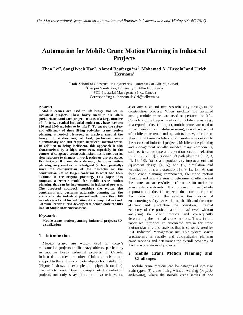
Alberta’s Hole School of Construction Engineering seeking solutions for planning crane motions. This research has been developed and implemented in actual projects built by PCL Industrial Management Inc. A case is selected to demonstrate the designed system and the planning results. The pick-and-swing analysis is built in a VB.Net® programming environment and shares information with an internal company database that stores project and crane data. The detailed crane motion planning algorithm is implemented in 3ds Max by coding in MAXScript (a built-in platform available to developers in 3ds Max).
MOTION PLANNING AUTOMATION 1 forall crane C 2 CLs UCLs 3 forall CL CLs 4 Pick-and-swing() 5 if Pick-and-swing.result = SUCCESS 6 Crane-Motion-Detailed-Planning() 7 else crane-walking() 8 if crane-walking.result = SUCCESS 9 Crane-Motion-Detailed-Planning() 10 else at CL lift impossible 11 end if 12 end if *Crane = one crane configuration; C = set of all craneconfiguration; CLs= crane locations for one Crane; UCLs = universal crane locations for C; CL = one crane location belonging to CLs.
Figure 7. Pseudo-code for crane motion planning
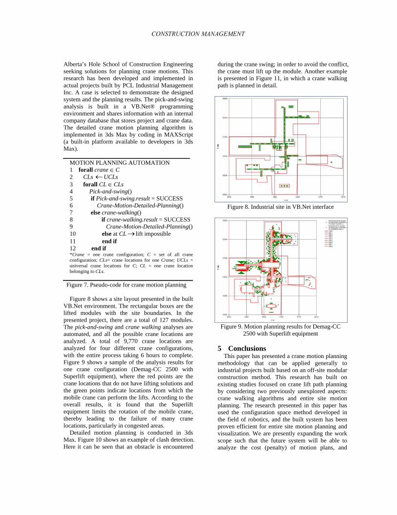
Figure 8 shows a site layout presented in the built VB.Net environment. The rectangular boxes are the lifted modules with the site boundaries. In the presented project, there are a total of 127 modules. The pick-and-swing and crane walking analyses are automated, and all the possible crane locations are analyzed. A total of 9,770 crane locations are analyzed for four different crane configurations, with the entire process taking 6 hours to complete. Figure 9 shows a sample of the analysis results for one crane configuration (Demag-CC 2500 with Superlift equipment), where the red points are the crane locations that do not have lifting solutions and the green points indicate locations from which the mobile crane can perform the lifts. According to the overall results, it is found that the Superlift equipment limits the rotation of the mobile crane, thereby leading to the failure of many crane locations, particularly in congested areas.
Detailed motion planning is conducted in 3ds Max. Figure 10 shows an example of clash detection. Here it can be seen that an obstacle is encountered
during the crane swing; in order to avoid the conflict, the crane must lift up the module. Another example is presented in Figure 11, in which a crane walking path is planned in detail.
Figure 8. Industrial site in VB.Net interface
Figure 9. Motion planning results for Demag-CC 2500 with Superlift equipment
5 Conclusions This paper has presented a crane motion planning
methodology that can be applied generally to industrial projects built based on an off-site modular construction method. This research has built on existing studies focused on crane lift path planning by considering two previously unexplored aspects: crane walking algorithms and entire site motion planning. The research presented in this paper has used the configuration space method developed in the field of robotics, and the built system has been proven efficient for entire site motion planning and visualization. We are presently expanding the work scope such that the future system will be able to analyze the cost (penalty) of motion plans, and
CONSTRUCTION MANAGEMENT

thereby will seek optimal plans for crane operations.
Figure 10. Clash detection
Figure 11. Crane walking planning
6 Acknowledgements
The authors wish to acknowledge the financial support of the Natural Sciences and Engineering Research Council of Canada (NSERC) Collaborative Research and Development (CRD) program. The support of our partner for this research, PCL Industrial Management Inc., is appreciated. Mr. Jonathan Tomalty’s assistance in editing is also
much appreciated.
References
[1] AlBahnassi, H., and Hammad, A. Near real-time motion planning and simulation of cranes in construction: Framework and system architecture. Journal of Computing in Civil Engineering, 26(1): 54-63, 2012.
The 31st International Symposium on Automation and Robotics in Construction and Mining (ISARC 2014)

[2] Ali, M. S. A. D., Babu, N. R., and Varghese, K. Collision free path planning of cooperative crane manipulators using genetic algorithm. Journal of Computing in Civil Engineering, 19(2): 182-193, 2005.
[3] Chang, Y. C., Hung, W. H., and Kang, S. C. A fast path planning method for single and dual crane erections. Automation in Construction, 22: 468-480, 2012.
[4] Hasan, S., Bouferguène, A., Al-Hussein, M., Gillis, P., and Telyas, A. Productivity and CO2 emission analysis for tower crane utilization on high-rise building projects. Automation in Construction, 31: 255-264, 2013.
[5] Hasan, S., Al-Hussein, M., Hermann, U. H., and Safouhi, H. Interactive and dynamic integrated module for mobile cranes supporting system Design. Journal of Construction Engineering and Management, 136(2): 179-186, 2010.
[6] Hermann, U., Hendi, A., Olearczyk, J., and Al-Hussein, M. An integrated system to select, position, and simulate mobile cranes for complex industrial projects. In Proceedings of the Construction Research Congress, pages 267-276, Alberta, Canada, 2010.
[7] Huang, C., Wong, C. K., and Tam, C. M. Optimization of tower crane and material supply locations in a high-rise building site by mixed-integer linear programming. Automation in Construction, 20(5): 571-580, 2011.
[8] Kang, S. C., Chi, H. L., and Miranda, E. Three-dimensional simulation and visualization of crane assisted construction erection processes. Journal of Computing in Civil Engineering, 23(6): 363-371, 2009.
[9] Kang, S. C., and Miranda, E. Planning and visualization for automated robotic crane erection processes in construction. Automation in Construction, 15(4): 398-414, 2006.
[10] Latombe, J. C. Robot Motion Planning. Kluwer Academic Publishers, Norwell, MA, 1991.
[11] Lei, Z., Taghaddos, H., Hermann, U., and Al-Hussein, M. A methodology of mobile crane lift path checking in heavy industrial projects. Automation in Construction, 31: 41-53, 2013.
[12] Li, Y., and Liu, C. Integrating field data and 3D simulation for tower crane activity monitoring and alarming. Automation in Construction, 27:111-119, 2012.
[13] Lin, Y., Wu, D., Wang, X., Wang, X., and Gao, S. Statics-based simulation approach for two-crane lift. Journal of Construction Engineering and Management, 138(10): 1139-1149, 2012.
[14]Lozano-Pérez, T. Spatial planning: A configuration space approach. IEEE Transactions on Computers, 32(2): 108-119, 1983.
[15] Olearczyk, J., Hermann, U., Al-Hussein, M., and Bouferguène, A. Spatial trajectory analysis of cranes operations on construction sites. In Proceedings of the Construction Research Congress, pages 359-368, Banff, Alberta, Canada, 2010.
[16] Safouhi, H., Mouattamid, M., Hermann, U., and Hendi, A. An algorithm for the calculation of feasible mobile crane position areas. Automation in Construction, 20(4): 360-367, 2011.
[17] Sawhney, A. and Mund, A. Adaptive probabilistic neural network-based crane type selection system. Journal of Construction Engineering and Management, 128(3): 265- 273, 2002.
[18] Sivakumar, P. L., Varghese, K., and Babu, N. R. Automated path planning of cooperative crane lifts using heuristic search. Journal of Computing in Civil Engineering, 17(3): 197-207, 2003.
[19] Wu, D., Lin, Y., Wang, X., Wang, X., and Gao, S. Algorithm of crane selection for heavy lifts. Journal of Computing in Civil Engineering, 25(1): 57-65, 2011.
CONSTRUCTION MANAGEMENT


![Automation for Mobile Crane Motion Planning in … · equipment design [4, 5]; and ... structures may be the foundations or the lifted piperack modules). ... Example of boom clash](https://img.pdfslide.us/doc/110x75/5b8e12e309d3f2187e8d0374/automation-for-mobile-crane-motion-planning-in-equipment-design-4-5-and.jpg)