Embed Size (px)
Citation preview
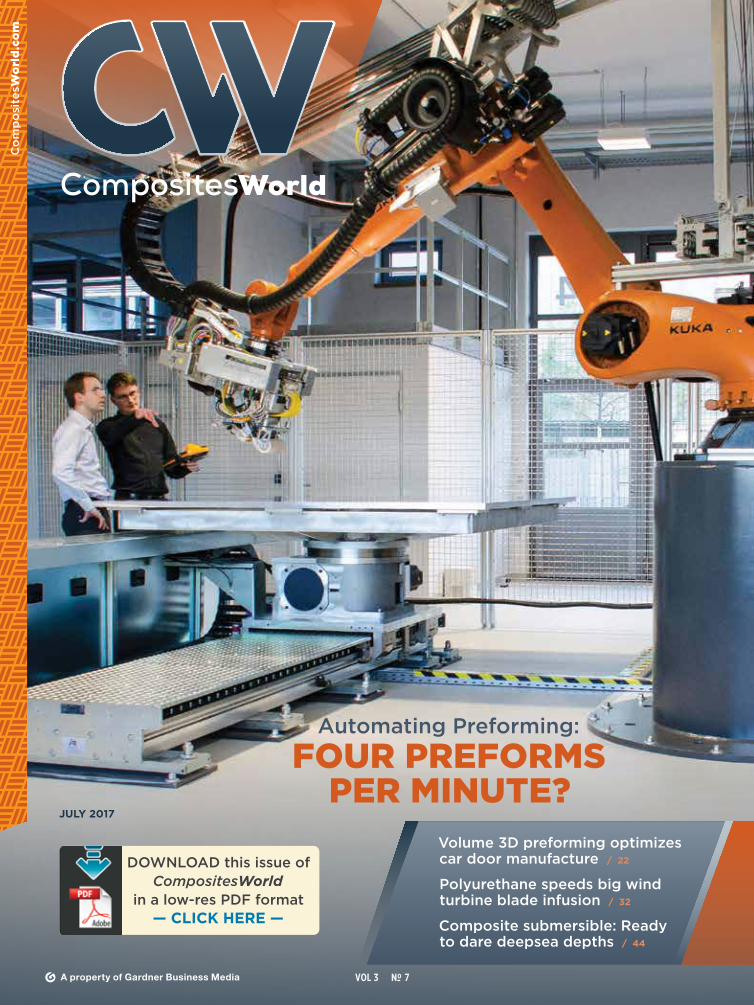
DOWNLOAD this issue ofCompositesWorld
in a low-res PDF format— CLICK HERE —
JULY 2017
VOL 3 No- 7A property of Gardner Business Media
Volume 3D preforming optimizes car door manufacture / 22
Polyurethane speeds big wind turbine blade infusion / 32
Composite submersible: Ready to dare deepsea depths / 44
Automating Preforming:
FOUR PREFORMS PER MINUTE?
BETTER PARTSLOWER COSTLET US SHOW YOU HOW
CONTACT US AT [email protected]
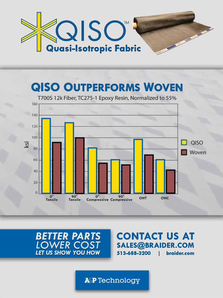
Quasi-Isotropic Fabric
513-688-3200 | braider.com
07106 AP Technologies.indd 1 6/8/16 11:11 AM
COLUMNS 4 From the Editor
6 Perspectives & Provocations
8 Design & Testing
12 Gardner Business Index
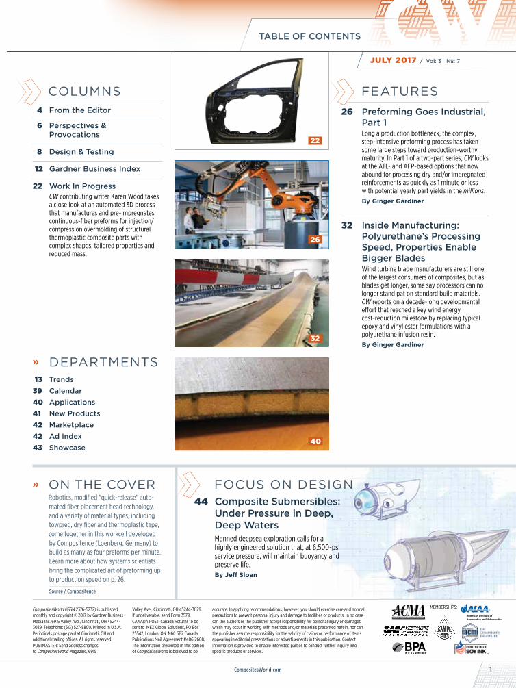
22 Work In ProgressCW contributing writer Karen Wood takes a close look at an automated 3D process that manufactures and pre-impregnates continuous-fiber preforms for injection/compression overmolding of structural thermoplastic composite parts with complex shapes, tailored properties and reduced mass.
» DEPARTMENTS 13 Trends39 Calendar40 Applications41 New Products42 Marketplace 42 Ad Index 43 Showcase
» ON THE COVER Robotics, modified "quick-release" auto-
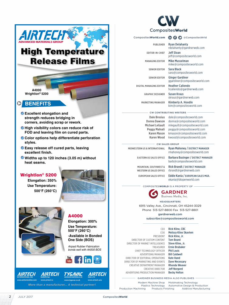
mated fiber placement head technology, and a variety of material types, including towpreg, dry fiber and thermoplastic tape, come together in this workcell developed by Compositence (Loenberg, Germany) to build as many as four preforms per minute. Learn more about how systems scientists bring the complicated art of preforming up to production speed on p. 26.
Source / Compositence
FOCUS ON DESIGN44 Composite Submersibles:
Under Pressure in Deep, Deep Waters Manned deepsea exploration calls for a highly engineered solution that, at 6,500-psi service pressure, will maintain buoyancy and preserve life.By Jeff Sloan
CompositesWorld (ISSN 2376-5232) is published monthly and copyright © 2017 by Gardner Business Media Inc. 6915 Valley Ave., Cincinnati, OH 45244-3029. Telephone: (513) 527-8800. Printed in U.S.A. Periodicals postage paid at Cincinnati, OH and additional mailing offices. All rights reserved. POSTMASTER: Send address changes to CompositesWorld Magazine, 6915
MEMBERSHIPS:Valley Ave., Cincinnati, OH 45244-3029. If undeliverable, send Form 3579.CANADA POST: Canada Returns to be sent to IMEX Global Solutions, PO Box 25542, London, ON N6C 6B2 Canada. Publications Mail Agreement #40612608. The information presented in this edition of CompositesWorld is believed to be
accurate. In applying recommendations, however, you should exercise care and normal precautions to prevent personal injury and damage to facilities or products. In no case can the authors or the publisher accept responsibility for personal injury or damages which may occur in working with methods and/or materials presented herein, nor can the publisher assume responsibility for the validity of claims or performance of items appearing in editorial presentations or advertisements in this publication. Contact information is provided to enable interested parties to conduct further inquiry into specific products or services.
FEATURES26 Preforming Goes Industrial,
Part 1Long a production bottleneck, the complex, step-intensive preforming process has taken some large steps toward production-worthy maturity. In Part 1 of a two-part series, CW looks at the ATL- and AFP-based options that now abound for processing dry and/or impregnated reinforcements as quickly as 1 minute or less with potential yearly part yields in the millions.By Ginger Gardiner
32 Inside Manufacturing: Polyurethane’s Processing Speed, Properties Enable Bigger BladesWind turbine blade manufacturers are still one of the largest consumers of composites, but as blades get longer, some say processors can no longer stand pat on standard build materials. CW reports on a decade-long developmental effort that reached a key wind energy cost-reduction milestone by replacing typical epoxy and vinyl ester formulations with a polyurethane infusion resin.By Ginger Gardiner
32
26
22
40
CompositesWorld.com 1
TABLE OF CONTENTS
JULY 2017 / Vol: 3 No–: 7
PUBLISHER Ryan Delahanty [email protected]
EDITOR-IN-CHIEF Jeff Sloan [email protected]
MANAGING EDITOR Mike Musselman [email protected]
SENIOR EDITOR Sara Black [email protected]
SENIOR EDITOR Ginger Gardiner [email protected]
DIGITAL MANAGING EDITOR Heather Caliendo [email protected]
GRAPHIC DESIGNER Susan Kraus [email protected]
MARKETING MANAGER Kimberly A. Hoodin [email protected]
CW SALES GROUP
MIDWESTERN US & INTERNATIONAL Ryan Mahoney / district manager [email protected]
EASTERN US SALES OFFICE Barbara Businger / district manager [email protected]
MOUNTAIN, SOUTHWEST & Rick Brandt / district manager WESTERN US SALES OFFICE [email protected]
EUROPEAN SALES OFFICE Eddie Kania / european sales mgr. [email protected]
HEADQUARTERS
6915 Valley Ave., Cincinnati, OH 45244-3029Phone 513-527-8800 Fax 513-527-8801
COMPOSITESWORLD IS A PROPERTY OF
ceo Rick Kline, CBC coo Melissa Kline Skavlem president Rick Kline, Jr. director of custom content Tom Beard director of market intelligence Steve Kline, Jr. treasurer Ernie Brubaker chief technology officer Phil Louis advertising manager Bill Caldwell director of editorial operations Kate Hand director of marketing and events Dave Necessary creative department manager Rhonda Weaver creative director Jeff Norgord advertising production manager Becky Helton
GARDNER BUSINESS MEDIA ALSO PUBLISHES
@CompositesWrld
CW CONTRIBUTING WRITERS
Dale Brosius [email protected] Donna Dawson [email protected] Michael LeGault [email protected] Peggy Malnati [email protected] Karen Mason [email protected] Karen Wood [email protected]
CompositesWorld.com
Modern Machine Shop Moldmaking Technology Plastics Technology Automotive Design & ProductionProduction Machining Products Finishing Additive Manufacturing
Wrightlon® 5200Elongation: 350%Use Temperature:
500°F (260°C)
A4000Elongation: 300%Use Temperature: 500°F (260°C)-Available in Bonded One Side (BOS)
Airpad Rubber Fabrication bonds well with A4000 BOS‐
Excellent elongation and strength reduces bridging in corners, avoiding scrap or rework.
High visibility colors can reduce risk of FOD and leaving film on cured parts.
Color options help differentiate perforation styles.
Easy release off cured parts, leaving excellent finish.
Widths up to 120 inches (3.05 m) without heat seams.
A4000Wrightlon® 5200
BENEFITS
INTERNATIONAL INC. EUROPE Sarl ASIA LTDADVANCED MATERIALS LTD
2 CompositesWorldJULY 2017
0717 OSG.indd 1 6/8/17 10:18 AM
JULY 20174 CompositesWorld
FROM THE EDITOR
» It’s almost impossible to travel anywhere within the world of
composites these days without confronting the topics of employ-
ment, training, employee retention or automation. At trade shows,
conferences and plant visits, there has been (for several years
now) ongoing discus-
sion about how to find
and retain employees who
either know and under-
stand composite materials or
demonstrate a willingness and
aptitude to learn about them.
This challenge is made all the more urgent by three compli-
cating factors. First, Baby Boomers. The Baby Boomer generation,
which includes anyone born between 1946 and 1964, is rapidly
retiring from the workforce. In the US, they leave at the rate of
about 10,000 per day, according to the US Social Security Admin.
Baby Boomers represent the foundation of the modern compos-
ites industry, and with their departure goes not just the ability to
do a job but, perhaps more importantly, the accumulated intel-
lectual capital and experience that is extremely difficult — if not
impossible — to replace.
Second, young people entering the workforce are not naturally
drawn to composites manufacturing. As important as composites
are to us, they represent a fraction of the overall global manufac-
turing economy. Drawing young people to composites requires
outreach and marketing that we are unused to doing. That said,
there are many universities and community colleges that teach
about composites and produce technicians and engineers who
understand the materials, but demand still far outweighs supply.
Third, employees, in general, are just difficult to find. In the
United States, the unemployment rate has dropped to 4.3%, which
represents, theoretically, “full employment.” In my home state of
Colorado, the rate has dropped to an all-time low of 2.3%, and it’s
rare, here, to see a retailer who does not have a “help wanted” sign
posted on its door. In the 29 countries of the EU, the unemploy-
ment rate is higher, hovering around 8%, so ostensibly the supply
of workers there is not as tight.
Against the backdrop of these workforce concerns, automation
presents itself as an ideal solution, yet it also presents its own set
of challenges.
To be sure, automation could solve a couple of major problems we
face. First, it would enable us to move away from the touch labor
required for hand layup of prepreg materials. This is easier said
than done, because the dexterity and utility of the human hand is
difficult to duplicate in an automated solution. But humans are also
notoriously inconsistent and prone to error, so the business case for
driving touch labor out of composites manufacturing is strong.
Second, and directly related to the first, automation can bring
to many composites fabrication processes a level of repeatability,
and cycle time and process control that could put the composites
manufacturing industry on par with more established manufac-
turing processes and materials, such as CNC machining or plastic
injection molding. In this way, composites manufacturing might
become more “standardized” and less of an outlier in the broader
manufacturing world. (And yes, I use the word “standardized” with
some hesitation because I know some of us don’t like to think that
composites manufacturing might one day be commoditized.)
Third, automation is, in fact, already happening. Despite the tech-
nical challenges, a number of enterprising machinery suppliers are
already offering, for example, production-line-worthy automated
preforming processes (see “Preforming goes industrial,” on p. 26).
Automation’s principal problem, of course, is that it displaces
humans in the workforce. Indeed, with little effort, one can find
online a variety of dark predictions about the pervasive and insid-
ious nature of automation throughout society — not just manufac-
turing — which might lead you to thoughts of The Terminator. The
more optimistic among us, however, believe that automation will
stimulate new opportunities for human work and endeavor that are
nearly impossible for us to predict or anticipate. Time will tell.
In the meantime, I am eager to see how the composites industry
addresses its workforce challenges, and we’ll do our best to keep you
up to speed.
Baby Boomers, work- force development
and automation.
JEFF SLOAN — Editor-In-Chief
REGISTER TODAY! www.IBEXShow.com/CW
SEPTEMBER 19–21, 2017 Tampa Convention Center I Tampa, FL USA
FUTURE MATERIALS DISPLAY:See the latest in materials and technologies from industries not easily accessed by marine professionals. Touch the technology of tomorrow’s boats. Curated by:
COMPOSITES PAVILION75 composites manufacturers & suppliers
SEMINAR SERIES Composite Methods & Materials track
SUPER SESSIONS Produced by Composites Pavilion exhibitors
NEW MATERIALS, PROCESSES, AND TECHNOLOGY
E HE KCD
T CON
ALL
0717 Ibex.indd 1 6/8/17 10:10 AM
JULY 20176 CompositesWorld
PERSPECTIVES & PROVOCATIONS
» A week before writing this, I went to the hardware store
to buy a pointed shovel. I had the choice of a shovel with a
wooden handle, or one with a composite handle — pultruded
fiberglass. I elected to buy the higher-priced composite-
handled shovel, partly because I’m a composites geek but also
because the shovel I was replacing has a composite handle
that I broke prying up tree roots. The failure mode was benign
in that the resin and fiber delaminated, but did not fully break
under the heavy load. I could laminate some glass and resin
over the top and it would still maintain some utility for light
work. I know from empirical experience that the same force
on a wooden handle would have snapped it in half, rendering
that shovel
completely
unusable.
That shopping
experience led
me to take inven-
tory of what other
composite products
I own — those that
can be purchased by anyone. Turns out I own a set of bypass
pruners that have fiberglass handles, as well as two tree pruners
with lightweight, extendible fiberglass poles, which are also
electrically insulative, in case you are trimming branches up
around power lines — a positive attribute, for sure!
Among my other tools, I have a stepladder with pultruded
side rails, and several types of hammers with fiberglass handles.
These are really great for vibration damping. And my sporting
goods collection is replete with composites, including a half-
dozen carbon fiber tennis racquets (used frequently), a set
of golf clubs with carbon fiber shafts (used less than I like),
a couple of carbon/glass fishing rods (that I haven’t used in
years — need to correct that), two pairs of fiberglass downhill
skis (used each winter) and a pair of carbon fiber downhill ski
poles that have performed flawlessly for almost 15 years. I had
a prototype pair of carbon fiber ski poles that I managed to
break in under a season, prior to these. Considering the shovel
and the poles, it sounds like I might have a future career as a
product tester.
Speaking of sporting goods, why do manufacturers still use
the term graphite when the product being used is what we
insiders call carbon fiber? It’s such an archaic term from the
1980s. The Ford Econoline driveshaft that won the SPE Auto-
motive Division Grand Award in 1984 is listed in the archives
as a “vinylester/graphite/glass” product when the fiber that
was used was a standard-modulus, AS4-type of carbon fiber.
Several of my newer Wilson tennis racquets, in fact, have
“Braided Graphite + Kevlar” printed on them, when it is obvious
that standard-modulus carbon fiber is used. The truth is that the
overwhelming majority of carbon fiber is produced with a carbon
content of 93-97%.
To be labeled graphite, the fiber needs to see heat treatment
well above 2000°C, and typically has more than 99% carbon assay.
When processed at these temperatures, the fibers develop highly
oriented graphitic structures and achieve very high modulus, as
well as high densities (often above 1.9 g/cm3). Examples include
Hexcel’s HM63 and Toray’s M60J in the PAN family, and the high-
modulus and high-conductivity grades of pitch-based fibers.
Very stiff and lightweight fishing rods and some golf shafts really
do use high-modulus graphite fibers, often in combination with
standard- and intermediate-modulus carbon fibers.
Although most of us deep in the industry call it carbon fiber,
I’ve seen forums on fishing equipment sites where buyers are
confused about terminology. In April of this year, I advocated here
that we need a public relations effort to create more awareness
of and provide education about composites among consumers.
Perhaps something along the lines of the American Chemistry
Council’s “Plastics Make It Possible” campaign would help. Maybe
“Composites – Built to Last” or something like that?
An article in the May issue of CompositesWorld about
composite foundation walls for residential housing made me want
to go out and build a new house just to take advantage of what
these panels offer in durability and energy efficiency — what an
exciting development! Like the fiberglass-handled shovel, the cost
of composite foundation walls is a bit more, so how do we help
the producers of these innovative building solutions reach critical
mass and generate pull from consumers, rather than depend
on push through builders and contractors? This is what a strong
public relations campaign could do for our industry.
And speaking of housing, I’ve come full circle. I’ve got some
yard work to do around my current residence. Time to put that
new shovel to use….
Composite musings
Dale Brosius is the chief commercialization officer for the Institute for Advanced Composites Manufacturing Innovation (IACMI, Knoxville, TN, US), a US Department of Energy (DoE)-sponsored public/private partnership targeting high-volume applications of composites in energy-related industries. He is
also head of his own consulting company and his career has included positions at US-based firms Dow Chemical Co. (Midland, MI), Fiberite (Tempe, AZ) and successor Cytec Industries Inc. (Woodland Park, NJ), and Bankstown Airport, NSW, Australia-based Quickstep Holdings. He also served as chair of the Society of Plastics Engineers Composites and Thermoset Divisions. Brosius has a BS in chemical engineering from Texas A&M University and an MBA.
How do we generate pull from consumers rather than depend on push through builders and contractors?
0717 IACMI.indd 1 6/8/17 10:13 AM
JULY 20178 CompositesWorld
DESIGN & TESTING
» In the past 15 years, progressive damage analysis (PDA) for
composites, implemented in finite element analysis software, has
been under development. Some PDA proponents argue that “virtual
testing” of this sort is, today, reliable enough to reduce or even
replace the conventional “building block” approach to composite
design that relies on physical testing. Although that could, in
some cases, save significant time and cost in the development of
composite structures, the results of a recent evaluation of the state
of the art in this area, overseen by the Air Force Research Laboratory
(AFRL, Wright-Patterson AFB, OH, US), indicates that comparative
experimental fatigue data do not yet justify such confidence.
Benchmarking PDA progressAn AFRL benchmarking exercise titled, “Damage Tolerance Design
Principles (DTDP),” conducted by Steve Engelstad of the Advanced
Development Program at Lockheed Martin Aeronautics Co.
(Lockheed Martin, Ft. Worth, TX, US) and myself from January 2014
through April 2015 asked the question, Can current PDA methods
accurately predict initiation and growth of damage in composites?
An intensive effort, it involved both static and fatigue blind predic-
tions, using several PDA methods. To evaluate existing tools for
composites damage progression modeling and prediction for future
application of damage growth analysis needs, AFRL, as an impartial
organizer, provided identical physical test data results to program
participants who would use the data for PDA model calibration/
validation. The static data included 0° tension and compression,
90° tension and compression, V-notch shear, 90° three-point bend,
Mode I double cantilever beam, and Mode II end-notched flexure.
The fatigue data included 0° S-N, 90° S-N, ±45° S-N, 90° three-point
bend S-N, Mode I double-cantilever beam fatigue, and Mode II end-
notched flexure fatigue. Since brittle failure in 90° matrix-dominated
tests resulted in low strength values and high fatigue scatter, AFRL is
currently conducting follow-on research to improve test methods.
Although there is not room here to examine the entire project,
comparisons of fatigue predictions derived via PDA against physical
open-hole fatigue test data for three different layups will serve to
illustrate what we learned. The ultimate goal of this effort was to
generate quality fatigue test results, along with high fidelity X-ray
CT images that would enable us to assess the ability of the PDA
methods to predict damage and residual strength after fatigue.
The layups were of IM7 HexTow carbon fiber (Hexcel, Stamford,
CT, US) and Cytec CYCOM 977-3 epoxy resin (Solvay Composite
Materials, Tempe, AZ, US), in the following ply sequences:
[0°/45°/90°/-45°]2S, [60°/0°/-60°]3S, [30°/60°/90°/-60°/-30°]2S.
It should be noted that in the static phase of the AFRL bench-
marking exercise, nine analysis teams had already performed blind
static predictions and then recalibrated the parameters in their
models based on the results of 12 experimental load cases. Lessons
learned during the program’s static portion included more accurate
How ready are progressive damage analysis tools?
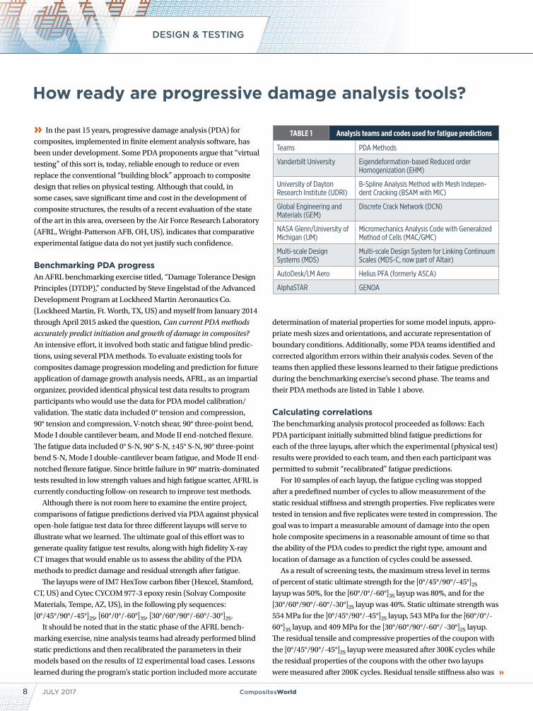
TABLE 1 Analysis teams and codes used for fatigue predictions
Teams PDA Methods
Vanderbilt University Eigendeformation-based Reduced order Homogenization (EHM)
University of Dayton Research Institute (UDRI)
B-Spline Analysis Method with Mesh Indepen-dent Cracking (BSAM with MIC)
Global Engineering and Materials (GEM)
Discrete Crack Network (DCN)
NASA Glenn/University of Michigan (UM)
Micromechanics Analysis Code with Generalized Method of Cells (MAC/GMC)
Multi-scale Design Systems (MDS)
Multi-scale Design System for Linking Continuum Scales (MDS-C, now part of Altair)
AutoDesk/LM Aero Helius PFA (formerly ASCA)
AlphaSTAR GENOA
determination of material properties for some model inputs, appro-
priate mesh sizes and orientations, and accurate representation of
boundary conditions. Additionally, some PDA teams identified and
corrected algorithm errors within their analysis codes. Seven of the
teams then applied these lessons learned to their fatigue predictions
during the benchmarking exercise’s second phase. The teams and
their PDA methods are listed in Table 1 above.
Calculating correlationsThe benchmarking analysis protocol proceeded as follows: Each
PDA participant initially submitted blind fatigue predictions for
each of the three layups, after which the experimental (physical test)
results were provided to each team, and then each participant was
permitted to submit “recalibrated” fatigue predictions.
For 10 samples of each layup, the fatigue cycling was stopped
after a predefined number of cycles to allow measurement of the
static residual stiffness and strength properties. Five replicates were
tested in tension and five replicates were tested in compression. The
goal was to impart a measurable amount of damage into the open
hole composite specimens in a reasonable amount of time so that
the ability of the PDA codes to predict the right type, amount and
location of damage as a function of cycles could be assessed.
As a result of screening tests, the maximum stress level in terms
of percent of static ultimate strength for the [0°/45°/90°/-45°]2S
layup was 50%, for the [60°/0°/-60°]3S layup was 80%, and for the
[30°/60°/90°/-60°/-30°]2S layup was 40%. Static ultimate strength was
554 MPa for the [0°/45°/90°/-45°]2S layup, 543 MPa for the [60°/0°/-
60°]3S layup, and 409 MPa for the [30°/60°/90°/-60°/ -30°]2S layup.
The residual tensile and compressive properties of the coupon with
the [0°/45°/90°/-45°]2S layup were measured after 300K cycles while
the residual properties of the coupons with the other two layups
were measured after 200K cycles. Residual tensile stiffness also was
10 CompositesWorld
DESIGN & TESTING
JULY 2017
measured after 1,000K cycles and 1,500K cycles. The purpose of the
higher cycle count tests was to assess the ability of the PDA codes
to predict stiffness degradation resulting from increasing levels of
damage from continued fatigue loading, or to predict the life of the
specimen if two-part failure occurred. The [0°/45°/90°/-45°]2S speci-
mens resulted in two-part failure prior to 2,000K cycles while the
other two layups experienced a stiffness reduction but not two-part
failure. This result proved to be a good indicator of the PDA capabili-
ties, because many codes predicted two-part failure in some cases
where the physical test specimens did not completely fail.
To enable observers to assess the ability of the PDA methods
to capture the correct damage type and location in the open-hole
fatigue specimens, X-ray tomographs were obtained intermittently
during the physical fatigue testing portion of the program. “Reca-
librated” models captured the location of damage relatively accu-
rately, and the discrete damage models, BSAM and DCN, due to
the discrete damage nature of their formulations, more distinctly
captured the narrow features of matrix cracks than the other models.
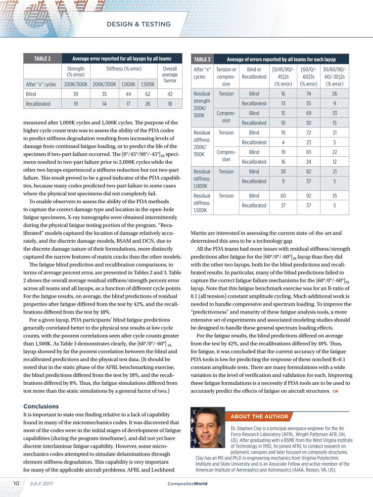
The fatigue blind prediction and recalibration comparisons, in
terms of average percent error, are presented in Tables 2 and 3. Table
2 shows the overall average residual stiffness/strength percent error
across all teams and all layups, as a function of different cycle points.
For the fatigue results, on average, the blind predictions of residual
properties after fatigue differed from the test by 42%, and the recali-
brations differed from the test by 18%.
For a given layup, PDA participants’ blind fatigue predictions
generally correlated better to the physical test results at low cycle
counts, with the poorest correlations seen after cycle counts greater
than 1,500K. As Table 3 demonstrates clearly, the [60°/0°/-60°] 3S
layup showed by far the poorest correlation between the blind and
recalibrated predictions and the physical test data. (It should be
noted that in the static phase of the AFRL benchmarking exercise,
the blind predictions differed from the test by 18%, and the recali-
brations differed by 8%. Thus, the fatigue simulations differed from
test more than the static simulations by a general factor of two.)
ConclusionsIt is important to state one finding relative to a lack of capability
found in many of the micromechanics codes. It was discovered that
most of the codes were in the initial stages of development of fatigue
capabilities (during the program timeframe), and did not yet have
discrete interlaminar fatigue capability. However, some micro-
mechanics codes attempted to simulate delaminations through
element stiffness degradation. This capability is very important
for many of the applicable aircraft problems. AFRL and Lockheed
ABOUT THE AUTHOR
Dr. Stephen Clay is a principal aerospace engineer for the Air Force Research Laboratory (AFRL, Wright Patterson AFB, OH, US). After graduating with a BSME from the West Virgina Institute of Technology in 1992, he joined AFRL to conduct research on polymeric canopies and later focused on composite structures.
Clay has an MS and Ph.D in engineering mechanics from Virginia Polytechnic Institute and State University and is an Associate Fellow and active member of the American Institute of Aeronautics and Astronautics (AIAA, Reston, VA, US).
Martin are interested in assessing the current state-of-the-art and
determined this area to be a technology gap.
All the PDA teams had more issues with residual stiffness/strength
predictions after fatigue for the [60°/0°/-60°]3S layup than they did
with the other two layups, both for the blind predictions and recali-
brated results. In particular, many of the blind predictions failed to
capture the correct fatigue failure mechanisms for the [60°/0°/-60°]3S
layup. Note that this fatigue benchmark exercise was for an R-ratio of
0.1 (all tension) constant amplitude cycling. Much additional work is
needed to handle compressive and spectrum loading. To improve the
“predictiveness” and maturity of these fatigue analysis tools, a more
extensive set of experiments and associated modeling studies should
be designed to handle these general spectrum loading effects.
For the fatigue results, the blind predictions differed on average
from the test by 42%, and the recalibrations differed by 18%. Thus,
for fatigue, it was concluded that the current accuracy of the fatigue
PDA tools is low for predicting the response of these notched R=0.1
constant amplitude tests. There are many formulations with a wide
variation in the level of verification and validation for each. Improving
these fatigue formulations is a necessity if PDA tools are to be used to
accurately predict the effects of fatigue on aircraft structures.
TABLE 3 Average of errors reported by all teams for each layup
After “x” cycles
Tension or compres-
sion
Bind or Recalibrated
[0/45/90/-45]2s
(% error)
[60/0/-60]3s
(% error)
30/60/90/-60/-30]2s (% error)
Residual strength 200K/ 300K
Tension Blind 16 74 26
Recalibrated 13 35 9
Compres-sion
Blind 15 69 33
Recalibrated 10 30 15
Residual stiffness 200K/ 300K
Tension Blind 10 72 21
Recalibrated 4 23 5
Compres-sion
Blind 19 65 22
Recalibrated 16 24 12
Residual stiffness 1,000K
Tension Blind 30 82 21
Recalibrated 9 37 5
Residual stiffness 1,500K
Tension Blind 60 92 35
Recalibrated 37 37 5
TABLE 2 Average error reported for all layups by all teams
Strength (% error)
Stiffness (% error) Overall average %error
After “x” cycles 200K/300K 200K/300K 1,000K 1,500K
Blind 39 35 44 62 42
Recalibrated 19 14 17 26 18

REGISTER TODAY AND SAVE!
CARBON FIBER 2017November 28-30, 2017
Belmond Charleston PlaceCharleston, South Carolina
2017
PRESENTED BY:
2017
Join the industry’s leading innovators, decision makers and key executives from all aspects of the carbon fiber
composites supply chain in scenic and historic Charleston, South Carolina for Carbon Fiber 2017!
At Carbon Fiber 2017 you’ll have access to cutting-edgeinformation and to industry experts in streamlining
manufacturing, reducing costs, market forecasting, and more.
SPONSORSHIPS AND EXHIBIT SPACE ARE STILL AVAILABLE CONTACT: Ryan Delahanty, Publisher | [email protected] | +1 513-766-5860
SILVER SPONSOR
DIAMOND SPONSOR
NEW IN 2017! Tour of Boeing 787 Dreamliner assembly facility in North Charleston, SC
DREAMLINER TOUR SPONSOR
2017 Carbon Fibers Global Outlook: Growth through Transportation and
Energy ApplicationsPRESENTED BY: Chris Red, Composites
Forecasts and Consulting LLC
DON'T MISS THE PRE-CONFERENCE
SEMINAR *
NOVEMBER 28 *Separate fee required
REGISTER EARLY AND SAVE! Register by October 16 and SAVE $100!
CarbonFiberEvent.com
CWCF17_RTS_FULL_univ.indd 1 5/12/17 7:19 AM
JULY 201712 CompositesWorld
GARDNER BUSINESS INDEX: COMPOSITES
US Composites index records its best reading in at least five years.
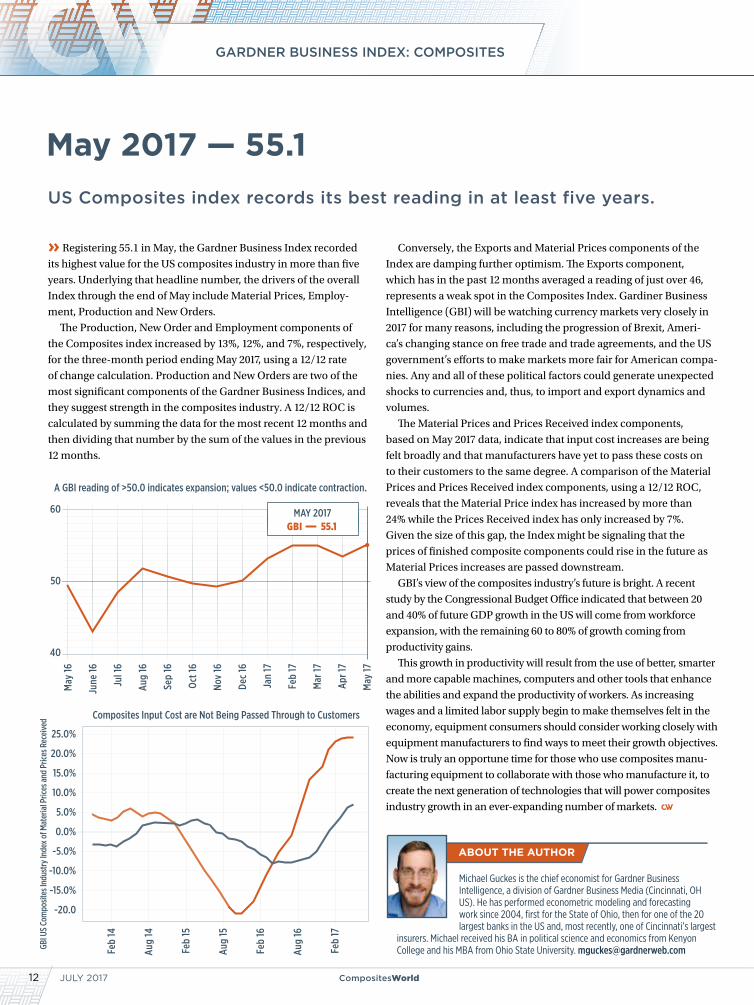
» Registering 55.1 in May, the Gardner Business Index recorded
its highest value for the US composites industry in more than five
years. Underlying that headline number, the drivers of the overall
Index through the end of May include Material Prices, Employ-
ment, Production and New Orders.
The Production, New Order and Employment components of
the Composites index increased by 13%, 12%, and 7%, respectively,
for the three-month period ending May 2017, using a 12/12 rate
of change calculation. Production and New Orders are two of the
most significant components of the Gardner Business Indices, and
they suggest strength in the composites industry. A 12/12 ROC is
calculated by summing the data for the most recent 12 months and
then dividing that number by the sum of the values in the previous
12 months.
Conversely, the Exports and Material Prices components of the
Index are damping further optimism. The Exports component,
which has in the past 12 months averaged a reading of just over 46,
represents a weak spot in the Composites Index. Gardiner Business
Intelligence (GBI) will be watching currency markets very closely in
2017 for many reasons, including the progression of Brexit, Ameri-
ca’s changing stance on free trade and trade agreements, and the US
government’s efforts to make markets more fair for American compa-
nies. Any and all of these political factors could generate unexpected
shocks to currencies and, thus, to import and export dynamics and
volumes.
The Material Prices and Prices Received index components,
based on May 2017 data, indicate that input cost increases are being
felt broadly and that manufacturers have yet to pass these costs on
to their customers to the same degree. A comparison of the Material
Prices and Prices Received index components, using a 12/12 ROC,
reveals that the Material Price index has increased by more than
24% while the Prices Received index has only increased by 7%.
Given the size of this gap, the Index might be signaling that the
prices of finished composite components could rise in the future as
Material Prices increases are passed downstream.
GBI’s view of the composites industry’s future is bright. A recent
study by the Congressional Budget Office indicated that between 20
and 40% of future GDP growth in the US will come from workforce
expansion, with the remaining 60 to 80% of growth coming from
productivity gains.
This growth in productivity will result from the use of better, smarter
and more capable machines, computers and other tools that enhance
the abilities and expand the productivity of workers. As increasing
wages and a limited labor supply begin to make themselves felt in the
economy, equipment consumers should consider working closely with
equipment manufacturers to find ways to meet their growth objectives.
Now is truly an opportune time for those who use composites manu-
facturing equipment to collaborate with those who manufacture it, to
create the next generation of technologies that will power composites
industry growth in an ever-expanding number of markets.
May 2017 — 55.1
Michael Guckes is the chief economist for Gardner Business Intelligence, a division of Gardner Business Media (Cincinnati, OH US). He has performed econometric modeling and forecasting work since 2004, first for the State of Ohio, then for one of the 20 largest banks in the US and, most recently, one of Cincinnati’s largest
insurers. Michael received his BA in political science and economics from Kenyon College and his MBA from Ohio State University. [email protected]
60
50
40
A GBI reading of >50.0 indicates expansion; values <50.0 indicate contraction.
May
16
June
16
Jul 1
6
Aug
16
Sep
16
Oct 1
6
Nov
16
Dec
16
Jan
17
Feb
17
Mar
17
Apr 1
7
May
17
55.1GBIMAY 2017
Composites Input Cost are Not Being Passed Through to Customers
Feb
14
Aug
14
Feb
15
Aug
15
Feb
16
Aug
16
Feb
17
25.0%
20.0%
15.0%
10.0%
5.0%
0.0%
-5.0%
-10.0%
-15.0%
-20.0
GBI U
S Co
mpo
sites
Indu
stry
Inde
x of M
ater
ial P
rices
and
Pric
es R
ecei
ved
A challenge to “outside the box” thinking about prepreg, a thought-provoking composites program at AIA, and rethinking a crane stinger with carbon fiber for a more “uplifting experience.”
CompositesWorld.com 13
TRENDS
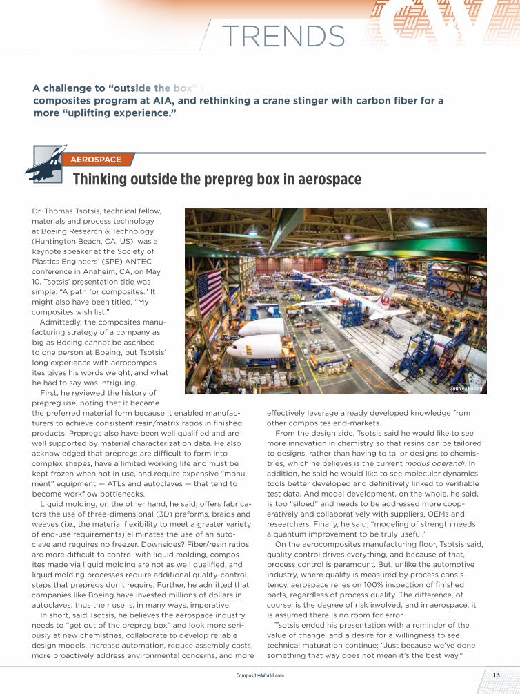
Dr. Thomas Tsotsis, technical fellow, materials and process technology at Boeing Research & Technology (Huntington Beach, CA, US), was a keynote speaker at the Society of Plastics Engineers’ (SPE) ANTEC conference in Anaheim, CA, on May 10. Tsotsis’ presentation title was simple: “A path for composites.” It might also have been titled, “My composites wish list.”
Admittedly, the composites manu-facturing strategy of a company as big as Boeing cannot be ascribed to one person at Boeing, but Tsotsis’ long experience with aerocompos-ites gives his words weight, and what he had to say was intriguing.
First, he reviewed the history of prepreg use, noting that it became the preferred material form because it enabled manufac-turers to achieve consistent resin/matrix ratios in finished products. Prepregs also have been well qualified and are well supported by material characterization data. He also acknowledged that prepregs are difficult to form into complex shapes, have a limited working life and must be kept frozen when not in use, and require expensive “monu-ment” equipment — ATLs and autoclaves — that tend to become workflow bottlenecks.
Liquid molding, on the other hand, he said, offers fabrica-tors the use of three-dimensional (3D) preforms, braids and weaves (i.e., the material flexibility to meet a greater variety of end-use requirements) eliminates the use of an auto-clave and requires no freezer. Downsides? Fiber/resin ratios are more difficult to control with liquid molding, compos-ites made via liquid molding are not as well qualified, and liquid molding processes require additional quality-control steps that prepregs don’t require. Further, he admitted that companies like Boeing have invested millions of dollars in autoclaves, thus their use is, in many ways, imperative.
In short, said Tsotsis, he believes the aerospace industry needs to “get out of the prepreg box” and look more seri-ously at new chemistries, collaborate to develop reliable design models, increase automation, reduce assembly costs, more proactively address environmental concerns, and more
effectively leverage already developed knowledge from other composites end-markets.
From the design side, Tsotsis said he would like to see more innovation in chemistry so that resins can be tailored to designs, rather than having to tailor designs to chemis-tries, which he believes is the current modus operandi. In addition, he said he would like to see molecular dynamics tools better developed and definitively linked to verifiable test data. And model development, on the whole, he said, is too “siloed” and needs to be addressed more coop-eratively and collaboratively with suppliers, OEMs and researchers. Finally, he said, “modeling of strength needs a quantum improvement to be truly useful.”
On the aerocomposites manufacturing floor, Tsotsis said, quality control drives everything, and because of that, process control is paramount. But, unlike the automotive industry, where quality is measured by process consis-tency, aerospace relies on 100% inspection of finished parts, regardless of process quality. The difference, of course, is the degree of risk involved, and in aerospace, it is assumed there is no room for error.
Tsotsis ended his presentation with a reminder of the value of change, and a desire for a willingness to see technical maturation continue: “Just because we’ve done something that way does not mean it’s the best way.”
AEROSPACE
Thinking outside the prepreg box in aerospace
Source | Boeing
TRENDS
INDUSTRIAL
JULY 201714 CompositesWorld
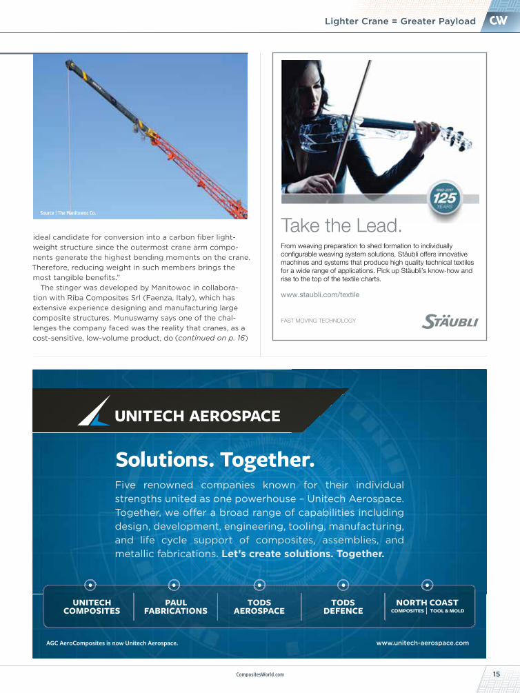
The payload capacity of a crane depends on the strength and stiffness of the materials used to make the arm. It also depends, ironically, on the arm’s weight. That is, the greater the arm’s weight, the less payload it can bear. Conversely, you can increase the payload capacity of the crane by reducing the mass of its arm. In other words, the crane arm is an ideal application for composites.
The Manitowoc Co., a crane manufacturer located in Shady Grove, PA, US, recognized this advantage and decided to target the stinger or fly jib — the final segment of a articulating crane arm — on one of its truck-mounted cranes, replacing the traditional 24-ft (7.3m) steel struc-ture with one of carbon fiber composite.
Sammy Munuswamy, senior principal engineer, global engineering and innovation at Manitowoc, says the company is “in the business of building lifting experiences for our customers around the world.” And a quality “lifting experience,” in Manitowoc’s view, should be one where the tool (crane) facilitates the jobs to be done at a variety of jobsite environments, including buildings, roadsides, heavy construction sites and more. “Cranes are getting lighter,” Munuswamy says, “and we need materials to meet that expectation. The stinger section was identified as an
Unweighting a crane to increase payload limit
ANNIVERSARY
02HPC
CharterAdvertiser
PRESENTERS
PRESENTED BY
siemens.com/plm
YVAN BLANCHARDSoftware Business
Development, Coriolis Software
EVENT DESCRIPTION: Complex composites structures are becoming more common, especially in aeronau-tics. Composites preforms can now be manufactured by automated processes, such as automated fiber placement (AFP) and automated tape laying (ATL), to achieve the expected production volumes.
This presentation will illustrate how Coriolis Software and Siemens PLM Software products can help composite designers, stress engineers, and NC programmers to collaborate together to optimize the design and manufacturing of complex CFRP laminates made by automated layup machines.
PARTICIPANTS WILL LEARN: • how to predict manufacturing issues early in the design stage• how to improve the collaboration between composite design, stress analysis, and NC programming• the key factors for design for manufacturing with automated layup robots • how to optimize part design - doing trade-off studies with machine limitations and for various material types
Lightweight Composite Design with Automated Layup Manufacturing
July 19, 2017 • 11:00 AM EST
REGISTER TODAY FOR WEBINAR AT: short.compositesworld.com/Siemens719
LEIGH HUDSONBusiness Development, Siemens PLM Software
15CompositesWorld.com
NEWSLighter Crane = Greater Payload
ideal candidate for conversion into a carbon fiber light-weight structure since the outermost crane arm compo-nents generate the highest bending moments on the crane. Therefore, reducing weight in such members brings the most tangible benefits.”
The stinger was developed by Manitowoc in collabora-tion with Riba Composites Srl (Faenza, Italy), which has extensive experience designing and manufacturing large composite structures. Munuswamy says one of the chal-lenges the company faced was the reality that cranes, as a cost-sensitive, low-volume product, do
Source | The Manitowoc Co.
(continued on p. 16)
Take the Lead.From weaving preparation to shed formation to individually configurable weaving system solutions, Stäubli o�ers innovative machines and systems that produce high quality technical textiles for a wide range of applications. Pick up Stäubli’s know-how and rise to the top of the textile charts.
www.staubli.com/textile
C
M
Y
CM
MY
CY
CMY
K
Five renowned companies known for their individual strengths united as one powerhouse – Unitech Aerospace. Together, we o� er a broad range of capabilities including design, development, engineering, tooling, manufacturing, and life cycle support of composites, assemblies, and metallic fabrications. Let’s create solutions. Together.
Solutions. Together.
www.unitech-aerospace.com
COMPOSITES TOOL & MOLDUNITECH
COMPOSITESPAUL
FABRICATIONSTODS
AEROSPACETODS
DEFENCENORTH COAST
AGC AeroComposites is now Unitech Aerospace.
TRENDS
JULY 201716 CompositesWorld
not allow for expensively engineered structures. In addi-tion, the composite stinger is a drop-in replacement for its predecessor.
Because the carbon fiber stinger works as a component retrofit compatible with existing cranes, RIBA’s engineers exploited all the available design space, maximizing the moment of inertia and the geometric properties of the stinger. The result is a hybrid structure where steel and composite match to take advantage of the specific proper-ties of each material. The junction between steel and composite relies on bonding and bolts, which allow an efficient solution.
Andrea Bedeschi, general manager at Riba, says the composite stinger is hand-laid, using carbon fiber prepreg and autoclave cure. The carbon fiber, standard-modulus 12K and 24K tow, is supplied by Mitsubishi and Toho Tenax. The resin is a toughened epoxy. Riba performed NDT eval-uation of the stinger; physical load, stability and structural performance testing was done by Manitowoc.
The composite stinger is 35% lighter than its steel prede-cessor and, says Munuswamy, increases payload capacity 12-15% more than the steel version in some specific boom configurations. The composite stinger also is more expen-sive than its steel predecessor, but Munuswamy says this is more than compensated for by increased jobsite efficiency and transportability.
Will Manitowoc expand carbon fiber use to other crane components? “This [the stinger] is leading us in that direc-tion,” Munuswamy says. “The stinger was the first step.”
(continued from p. 15)
+1 (775) 827-6568 • www.abaris.com
USA LATIN AMERICA EUROPE
• EXPLORE Our Training Programs
• DISCOVER Best Industry Practices
• GAIN Applicable Lifetime Skills
High Performance Tooling for the Composites Industry
• Steel• Invar• NVD Nickel• Aluminum• Precision Machining [email protected]
webermfg.ca
17CompositesWorld.com
NEWSBiz Briefs
Production-grade 3D printing solutions provider Methods 3D Inc. (Sudbury, MA, US) announced a partnership with Markforged (Somerville, MA), the inventor of a proprietary continuous carbon fiber filament 3D printing method. Methods 3D will provide sales, service and support for the Markforged line of 3D printers, including the Onyx series, Mark Two and Mark X. The partnership is expected to expand North American manufacturers’ access to both companies’ printing solutions and enable Methods Machine Tools’ Automation Group to design, integrate and sell solutions for its CNC machining automation systems, with the ability to print unique end-of-arm tooling for robots, jigs, fixtures and more.
Surface Generation (Rutland, UK) completed delivery of its largest-ever PtFS (Production to Functional Specifications) tooling system to advanced composites manufacturer Quatro Composites (Poway, CA, US). The modular PtFS system can be reconfigured for use in multiple projects and will be used on thermoplastic composite structures as part of a high-volume North American aircraft program. It is the first such system to incorporate more than 200 individually heated and cooled areas within tool faces, enabling compression and injection molders to adapt zoned heating and cooling levels and maintain more pre-cise thermal control when forming complex components.
LMT Onsrud’s CVD Diamond-Coated solid carbide
cutting tools optimize performance when machining
composite materials.
- Multi-Flute Composite Routers
- Low Helix Rougher Finishers
- Low Helix Cutters
- Composite Drills
- 4 & 6 Flute Compression Spirals
LMT Onsrud LP1081 S. Northpoint BlvdWaukegan, IL 60085Phone 800 234 1560
NEED TO INCREASE TOOL LIFE AND PART QUALITY?
Visit www.onsrud.com for more information
BIZ BRIEF
TRENDS
JULY 201718 CompositesWorld
Décision SA expands into architectural marketThe Switzerland-based composites manufacturer recently signed agreements for several composite roofs and other major structural elements.06/12/17 | short.compositesworld.com/DecisArch
Hexcel to launch CFRP/metal hybrid solutionThe technology combines a fast-curing carbon fiber/epoxy prepreg and a new film adhesive called Redux 677.06/12/17 | short.compositesworld.com/HexcelHybr
Daher announces new thermoplastic composite wing ribThe rib will be used in the test wing box built as part of the Composite Aircraft of the Future platform.06/12/17 | short.compositesworld.com/DaherTCRib
Chomarat joins UK-based Advanced Manufacturing Research CentreThe company, which will be the first textile producer to join AMRC, is also sponsoring a research collaboration focused on multiaxial carbon fiber fabrics.06/12/17 | short.compositesworld.com/ChomAMRC
Airbus: 35,000 new commercial aircraft needed over next 20 yearsIncreasing numbers of first-time flyers, rising disposable income and new routes are expected to drive demand for US$5.3 trillion in new aircraft. 06/12/17 | short.compositesworld.com/Airbus2036
Web Industries opens ply cutting and kitting operationThe new facility includes five cutting tables, laser guidance devices and quality control systems that ensure every ply in a kit is in the correct order.06/08/17 | short.compositesworld.com/WebPlyKit
DowAksa, Vestas sign agreement to develop carbon fiber spar caps for wind turbine bladesDowAksa expects to provide more than US$300 million worth of pultruded carbon fiber-reinforced spar caps over the projected four-year contract.06/07/17 | short.compositesworld.com/DowAksaCap
Stratolaunch composite aircraft rolls out, to begin fuel testsThe aircraft has a wingspan of 385 ft (117.4m) and is reportedly the largest composite aircraft ever built.06/05/17 | short.compositesworld.com/StratoRoll
Revolutionary fuselage concept unveiled by MTorresMade with carbon fiber composites but without fasteners or molds, this paradigm-changing monocoque could cut raw material cost by 10-30%.06/05/17 | short.compositesworld.com/NuFuselage
SGL Group leads research into carbon fiber-reinforced thermoplastic components for the automotive industryThe project aims to develop the technology necessary to support thermo-plastic composites for serial production at all levels of the value chain.06/05/17 | short.compositesworld.com/SGL-TPC
Notes about newsworthy events recently covered on the CW Web site. For more information about an item, key its link into your browser. Up-to-the-minute news | www.compositesworld.com/news/list
MONTH IN REVIEW
19CompositesWorld.com
NEWSACMA Pavilion at AIA Show
ARCHITECTURE
Composites continue to make inroads in fields of architecture and construction. At the 2017 American Institute of Architects (AIA, Washington, DC, US) exhibition and conference (April 27-29, Orlando, FL, US), there was again abundant evidence of that fact. The American Composites Manufacturers Assn’s. (ACMA) Architectural Division exhibited its 4th annual Composites Pavilion, which included Composites Central, a schedule of educational sessions presented by Division members, and the second annual Composites Challenge.
Coordinated by David Riebe, vice president of Windsor Fiberglass (Burgaw, NC, US), the Composites Challenge design competition annually tasks teams of architec-tural students to develop novel architectural/building components and/or assemblies using composite materials. As part of the Challenge, a series of composites-oriented work-shops, comprising both seminars and hands-on activities, were held this year at participating architec-ture schools, educating roughly 75 students — tomorrow’s architects.
In addition to the winning teams, which hailed from Clemson University (Clemson, SC, US, see top photo, p. 20) and the University of Southern California (Los Angeles, CA, US), teams from the University of North Carolina Charlotte and Kent State University (Kent, OH, US) also competed. Projects completed by the first, second and third place winners were on display in the Composites Pavilion.
Also featured in the Composites Pavilion was Composites Central, a principal feature of which was a daily schedule of 30-minute educational sessions. Available to AIA attendees, they were presented by members of ACMA’s Architectural Division.
ACMA’s 4th Annual Composite Pavilion
(continued on p. 20)
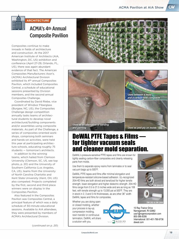
DeWAL’s pressure-sensitive PTFE tapes and films are known for tightly sealing carbon-fiber composites and cleanly releasing parts from molds. Use them to separate epoxy resins from laminates or to seal vacuum bags up to 500°F.DeWAL PTFE tapes and films offer minimal elongation and temperature-resistant silicone-based adhesion. UL-recognized 204-HD films are both skived and tensilized for higher tensile strength, lower elongation and higher dielectric strength. 204-HD films range from 0.5 to 21.5 inches wide and are as long as 108 feet, with tensile strength up to 13,000 psi at 500°F. They are in stock in 2, 3 and 5 mil thicknesses, as are other 36” width DeWAL tapes and films for composites. Whether you are doing open or closed molding, whether your process is lay-up, compression molding, resin transfer or continuous lamination, DeWAL will share a solution with you.
DeWAL PTFE Tapes & Films — for tighter vacuum seals and cleaner mold separation.
Used as an alternative to sanding and painting Used as peel-ply on molds
Used between a mold and a carbon-fiber composite
DW 134
DW 204-HD
DW 202 & DW 2000
15 Ray Trainor DriveNarragansett, RI 02882 [email protected] 800-366-8356 International: 001-401-789-9736dewal.com
Source | Fresh Air Building Systems LLC
TRENDS
JULY 201720 CompositesWorld
CORRECTIONIn CW’s recent coverage of the Google Lunar XPRIZE, (CW April 2017, pp. 34-38), it was reported that the privately funded, quali-fied participants in the Lunar XPRIZE race to Earth’s Moon must be the first to land a spacecraft on the Moon’s surface on or before Dec. 31 of this year. However, our article author and CW senior writer emeritus Donna Dawson tells us that this stipu-lation was altered in recogni-tion of the participating teams’ diverse mission plans, prior to article publication, and requires only that space system launch take place on or before Dec. 31. Landing a craft on the Moon’s surface can occur after that date, but the winning mission must have been initiated before year’s end. CW regrets missing the change in requirement.
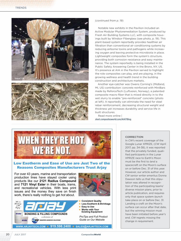
Notable new exhibits in the Pavilion included an Active Modular Phytoremediation System, produced by Fresh Air Building Systems LLC, with composite hous-ings built by Windsor Fiberglass (see photo, p. 19). This plant-based system reportedly provides healthier air filtration than conventional air conditioning systems by reducing airborne toxins and pathogens while increas-ing oxygen and leaving protective microbiota in place. Lightweight composites form the system’s structure, providing both corrosion resistance and easy mainte-nance. The system reportedly is being installed in the Public Safety Answering Center in the Bronx, NY, US. It’s presence at AIA in the Pavilion served to highlight the role composites can play, and are playing, in the growing wellness and health trend in the building construction and architecture markets.
Another eye-catcher was Owens Corning’s (Midland, MI, US) contribution: concrete reinforced with MiniBars made by ReforceTech (Luftveien, Norway), a patented composite macro fiber that is mixed directly in to the wet slurry to enable “pre-reinforced” concrete (photo at left). It reportedly can eliminate the need for steel rebar reinforcement, decreasing structural weight and thickness yet increases durability and service life in built structures.
Read more online | short.compositesworld.com/AIA17Blog
(continued from p. 19)
BONDING & FILLING COMPOUNDS
Low Exotherm and Ease of Use are Just Two of the Reasons Composites Manufacturers Trust Arjay
For over 43 years, marine and transportation production lines have stayed cooler using products like our 2121 Radius Compound and 7121 Vinyl Ester in their boats, trams, and recreational vehicles. With less print issues and the money they save on finish work, there’s really nothing to get hot about.
Consistent QualityLess Exotherm & ShrinkageEasy to UseWorks with Your Existing Equipment
www.arjayteCh.COM 919.598.2400 [email protected]
a division of ProTips and Full Product Guide on Our Website
“We’re Sticking
with Arjay”
Source | CW
Source | ReforceTech
Long-term North American wind outlook
21CompositesWorld.com
NEWSWind Energy Outlook 2017-2026
ENERGY
Wind energy industry consultancy MAKE (Chicago, IL, US) has issued its 2017 North America Wind Power Outlook, and in it, says the US will install approximately 59 GW of wind capacity from 2017-2026. Much of this will be driven in the initial four-year period, through 2020, by the still full-value production tax credit (PTC), which is expected to help account for 40 GW of the total.
MAKE expects that asset owners also will embark on the most exten-sive repowering campaign, thus far, in the US: Nearly 1 GW of existing turbine nacelle and blade units will be replaced with new components, while smaller components will be replaced in another 6 GW of existing turbines with the aim of extending operational lifespans and requalifying for the PTC.
The PTC, starting this year, begins a phase out: Wind projects begun in 2017 get an 80% PTC credit; projects begun in 2018 get a 60% PTC credit; and projects begun in 2019 get a 40% PTC credit. Because of this, projects could be excessively concentrated in 2020, which could strain resources. Beginning in 2022, wind power effec-tively will be left to compete solely on a levelized cost of energy (LCOE) basis. MAKE says that competition amid sustained low natural gas prices and the rapidly falling cost of solar power will reduce new wind installa-tions to the fraction of US states that then have favorable land availability, wind resources and transmission capacity. MAKE predicts that states in the central US “wind belt” will be particularly well-positioned to compete on LCOE, but to do so, will require major transmission build-out to access distant demand centers.
All wind projects will become more vulnerable in this coming low-margin environment: Previously surmount-able hurdles, such as state-level policy changes and permitting difficulties, will run a far greater risk of becoming project-killing obstacles.
Offshore wind power, however, will be the exception to the economics-driven installations of the post-PTC period, says MAKE. Supported by robust state-level policies in the Northeast region, the first full-scale
Working with Composites One gives you access to the broadest, deepest line of cast polymer and solid
surface PRODUCTS available from the industry’s top suppliers. Helping you navigate this one-stop-shop and making sure you
get what you need, when you need it, are technical sales experts and regional customer service reps, along with local support
teams at more than 35 distribution centers across the U.S. and Canada. All are backed by the service and support
that only North America’s leading composites distributor can provide.
That’s the power of One – Composites One.
800.621.8003 | www.compositesone.com | www.b2bcomposites.com
People | Product | Process | Performance
Visit us at Booth K32 to see LIVE advanced process demos during CAMX 2017 in Orlando, FL, September 11-14.
“With the broadest and deepest product line, along with the largest dedicated fleet of trucks in the composites industry, Composites One’s priority is to make sure you have what you need, when you need it.”Laura McClain, Distribution Center Manager, Lenexa, KS
CMP-440 CW half Island PAGE PRODUCT ad June 2017 FINAL.indd 1 6/7/17 12:23 PM
offshore projects will reach commercial operational level in 2021, and at least one new offshore wind farm develop-ment will be installed annually through 2026. Ultimately, according to MAKE, some 2.2 GW of offshore wind will enter commercial operation in US territorial waters within the forecast period.
JULY 201722 CompositesWorld
WORK IN PROGRESS
» New lightweighting solutions for the automotive industry
today must meet a plethora of demands. They must provide oppor-
tunities not only for weight savings but also cost savings in the
finished part. They also require materials of reasonable cost that
have the potential to be recycled. Thermoplastic-based composites
could fit the bill, but historically have been held back by inherent
processing challenges.
A novel thermoplastic composite preform technology called
QEE-TECH, developed by EELCEE Ltd. (Gyeonggi-do, South
Korea), and related processing equipment, offers a lightweighting
solution that reportedly meets these challenges. QEE-TECH is said
to enable complex 3D shaping of thermoplastic preforms. This,
in turn, reduces the cost and time required for high-throughput
processing of thermoplastic composites. The equipment was
manufactured by a joint venture company, QEESTAR, created
with Gyeonggi-do-based robotics company Robostar Co. Ltd.
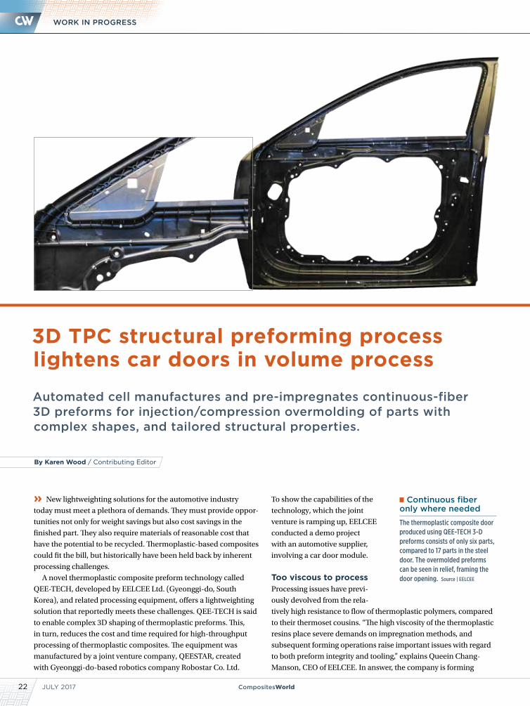
Automated cell manufactures and pre-impregnates continuous-fiber 3D preforms for injection/compression overmolding of parts with complex shapes, and tailored structural properties.
3D TPC structural preforming process lightens car doors in volume process
To show the capabilities of the
technology, which the joint
venture is ramping up, EELCEE
conducted a demo project
with an automotive supplier,
involving a car door module.
Too viscous to processProcessing issues have previ-
ously devolved from the rela-
tively high resistance to flow of thermoplastic polymers, compared
to their thermoset cousins. “The high viscosity of the thermoplastic
resins place severe demands on impregnation methods, and
subsequent forming operations raise important issues with regard
to both preform integrity and tooling,” explains Queein Chang-
Manson, CEO of EELCEE. In answer, the company is forming
Continuous fiber only where needed
The thermoplastic composite door produced using QEE-TECH 3-D preforms consists of only six parts, compared to 17 parts in the steel door. The overmolded preforms can be seen in relief, framing the door opening. Source | EELCEE
By Karen Wood / Contributing Editor
CompositesWorld.com 23
NEWS3D Preforming
prepregged fiber constructs and then placing the pre-impregnated
preform (the prepreg) into the mold and overmolding it. Thus, the
problem of poor impregnation of continuous fiber in the injection
or compression mold is avoided by impregnating the continuous
fiber outside of the mold and then placing the prepreg in the mold.
“By encapsulating unidirectional fiber and textile composite
inserts in injection and compression molded parts, QEE-TECH
provides a step-change in the design space for high-volume
composite materials and facilitates the integration of multiple
functions in a single part,” she explains. “This allows the designer
the freedom to optimize both cost and performance by placing
expensive, high-performance continuous fiber material only where
it is required while still maintaining the shape freedom afforded by
lower cost, lower performance ‘flowable’ materials.”
“We have demonstrated 20-30% weight reduction (in excep-
tional cases up to 50%) and 10-20% cost reduction in a range of
applications,” she adds.
CW first covered EELCEE back in 2013 after the company won a
JEC Innovation Award at the 2013 JEC Asia event in Singapore for
a thermoplastic bumper system manufactured via 3D QEE-TECH
by molder Hanwha for Hyundai-KIA Motor Group, both based in
Seoul, South Korea, (see Learn More, p. 25).
More recently, at SPE’s 2016 Automotive Composites Confer-
ence & Exhibition in Novi, MI, US, Chang-Manson discussed the
use of the company’s technology in the high-volume manufacture
of composite automotive parts.
Automated processThe QEE-TECH 3D preform cell is designed to manufacture parts
with complex shapes, multiple functions and tailored structural
properties in a single-step operation. The fully automated process
begins by pulling multiple continuous carbon or glass fiber rovings
or tows from a creel through a series of dies that wet out the fiber
with the appropriate resin (PA, PP, ABS, PEEK, etc.).
“Glass fiber has shown to be a preferred alternative when
strength is the main requirement, while carbon fiber may be
preferred if high stiffness is a priority,” says Chang-Manson.
The material passes through a preheating oven during the
wet-out process. Next, the homogeneous molten tow is deposited
on a jig fixed to a rotating, sliding or tilting table robot. A consolida-
tion roller applies pressure to the tow during deposition. In all, the
cell employs three robots — a head robot system that deposits the
material, the table robot system, and a support robot system.
By rapidly placing the composite material into the desired
3D shape, an open, tailored 3D skeleton (prepreg) is created.
Placed material is cooled via an air-jet system. The finished, solid
composite preform is then automatically cut and moved to the over-
molding operation.
Fully automated, the QEE-TECH cell can be synchronized to inte-
grate overmolding operations, providing high layup rates at temper-
atures up to 400°C. The 3D preforming process is completed within
a cycle time on the order of 60 seconds.
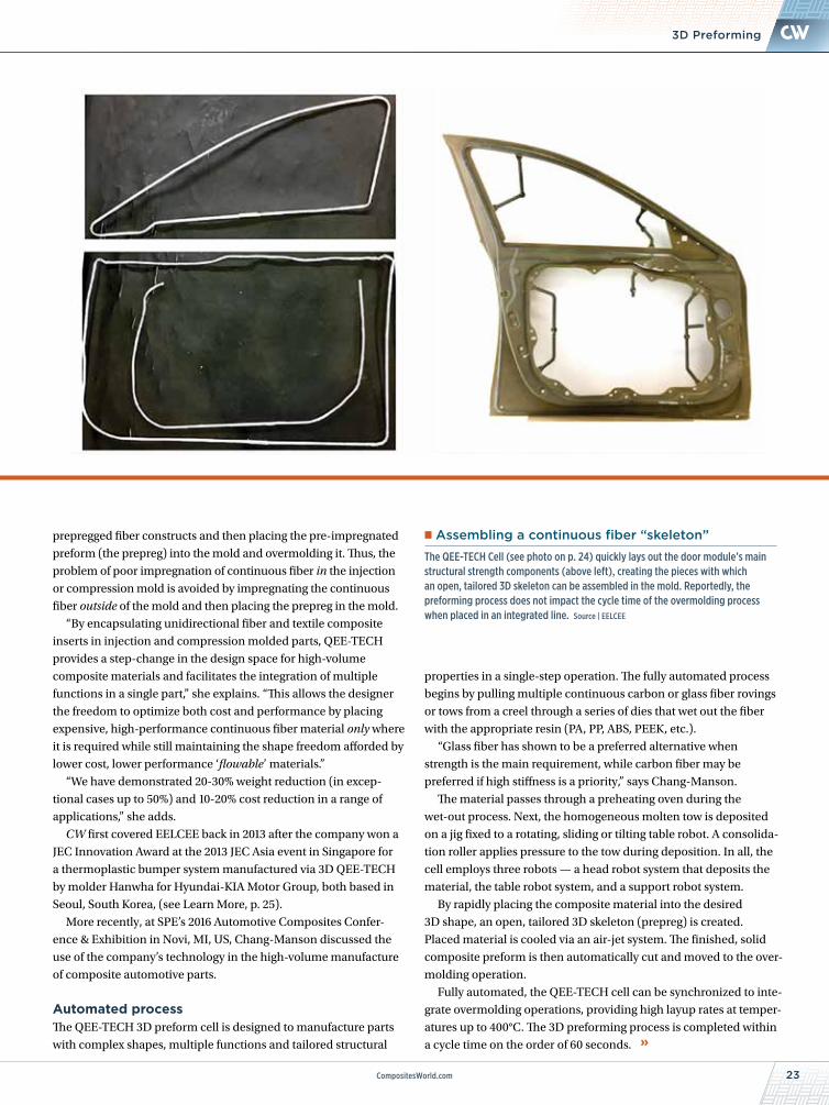
Assembling a continuous fiber “skeleton”
The QEE-TECH Cell (see photo on p. 24) quickly lays out the door module’s main structural strength components (above left), creating the pieces with which an open, tailored 3D skeleton can be assembled in the mold. Reportedly, the preforming process does not impact the cycle time of the overmolding process when placed in an integrated line. Source | EELCEE
JULY 201724 CompositesWorld
WORK IN PROGRESS
“QEE-TECH is designed for the production of structural compo-
nents in high volume,” stresses Chang-Manson. “Each cell offers
a cycle time of less than one minute, producing from 10,000 to
300,000 parts per year.”
Typically, conventional neat or short fiber-reinforced polymers
(PA, PP, PET, ABS, etc.) are used in the over-molding operation,
typically injection or compression molding. “It is a non-isothermal
process,” explains Chang-Manson. “The insert is preheated to
just below melt, and the overmolding material has a temperature
above melt. By doing this, the injection molding pressure enables
a low void content and good bonding between the insert and the
overmolded polymer, with a cycle time that is the same as for
normal injection molding,” she adds. Reportedly, the preforming
process does not negatively impact the cycle time of an over-
molding process like injection molding when it is integrated into a
production line. The cell can be integrated with other composites
manufacturing technologies, such as RTM and thermoforming.
Composite door moduleEELCEE recently partnered with Duckyang Ind. Co. Ltd. and MS
Autotech Co. (both automotive parts manufacturers based in
South Korea) to develop a composite door module. The research
was supported by the Ministry of Trade, Industry & Energy
(MOTIE), and the Korea Institute for Advancement of Technology
(KIAT) through the “Encouragement Program for The Industries
of Economic Cooperation Region.”
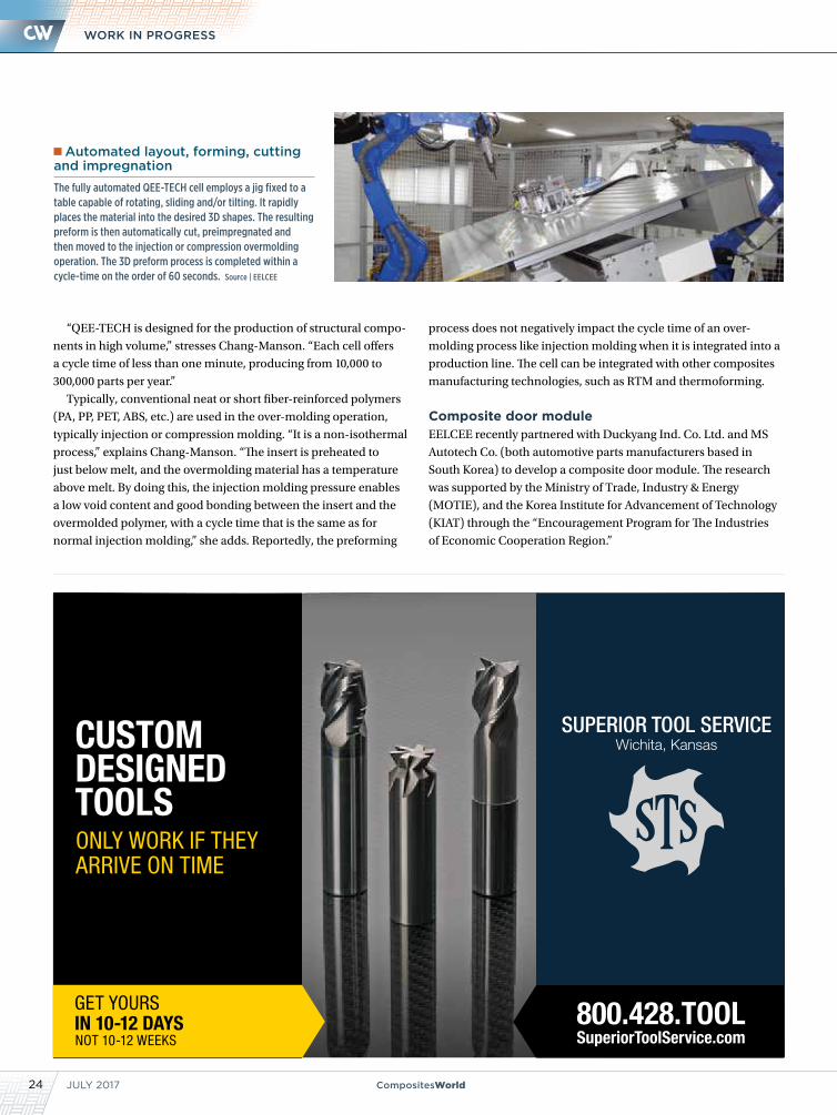
Automated layout, forming, cutting and impregnation
The fully automated QEE-TECH cell employs a jig fixed to a table capable of rotating, sliding and/or tilting. It rapidly places the material into the desired 3D shapes. The resulting preform is then automatically cut, preimpregnated and then moved to the injection or compression overmolding operation. The 3D preform process is completed within a cycle-time on the order of 60 seconds. Source | EELCEE
CompositesWorld.com 25
NEWS3D Preforming
F148CH33 COMPACT HIGH RAIL
120 Technology Drive • Troutman, NC 28166
www.cronsrud.com© Copyright 2017, C.R. Onsrud Incorporated. All rights reserved.
Advanced Materials • Non-Ferrous MetalsHigh-Speed Machining • Large Part/Envelope Machining
The newly redesigned Compact High Rail Series CNC machining
center is based on the proven dependability of a heavy, engineered
and precision welded steel base. We created a roomier cutting
envelope for large material while still delivering the power, rigidity
and accuracy this platform is known for. The new 5-Axis Compact
High Rail by C.R. Onsrud is a CNC machine for serious applications.
Powered by:
#depend
Come See Us at
BOOTH #B9September 11-14, 2017
Orlando, FL
CW
-07|
2017
“The value of this concept lies primarily
in the weight, cost and sub-part reduction
that it offers with respect to a metal door
module in the same price range,” explains
Chang-Manson. By using continuous fiber
preforms as local reinforcements in the
thermoplastic door, a weight reduction of
up to 20% can be achieved, she adds.
For the door module, EELCEE used
a proprietary system it calls M-Tow — a
braiding system that encapsulates the
incoming unidirectional (UD) fiber tow
with a suitable braid of fiber and/or
polymer. This allows the tow to be heated
and reshaped during the subsequent
automated layup process without any loss
of composite consolidation and polymer
exudation. It also allows the braided tow
to be self-supported during any form of
3-D layup.
The QEE-TECH process enables users to
place a variety of 3D preforms for dedicated
load introduction and load distribution.
With proper design, it also can reduce the
number of subparts. In this case, the ther-
moplastic composite door module consists
of only six parts, compared to 17 parts in the
legacy steel door.
“In developing the part, the whole value
chain needs to be considered: manufac-
turing process and tool design, assembly
and end-of-life,” notes Chang-Manson.
“The introduction of local inserts can
improve performance, but they entail an
increase in complexity. It is very important
to define which aspects of performance
should be prioritized to keep complexity to
a minimum.”
Re-engineering of the door focused not
only on reducing its weight but also on
engineering in greater strength. Exten-
sive testing is being performed on various
preforms with different material combina-
tions and shape configurations to verify
process reliability and product
performance.
“Our partners are pleased with
the prototype parts that have been
produced,” says Chang-Manson.
“They are dimensionally stable and
the parts look promising for high-
volume production.” Hyundai Motor Co. reportedly has followed the door project
closely and is considering adopting the technology for production. After testing is
completed, EELCEE plans to contact other OEMs.
Read this article online | short.compositesworld.com/3D-TDC
Read CW’s previous coverage of EELCEE’s technology online in “Structural preform technologies emerge from the shadows” | short.compositesworld.com/Mqzr7Fg7
CW contributing writer Karen Wood previously served as managing editor of Injection Molding Magazine (Denver, CO, US)[email protected]
JULY 201726 CompositesWorld
Preforming goes industrial, Part 1
ATL- and AFP-based options now abound for processing dry and/or impregnated reinforcements as quickly as 1 minute or less with potential yearly part yields in the millions.
» In the race to reduce the cost and cycle time of composite
parts, automation has successfully transformed cutting, molding
and machining into processes more suited to industrial produc-
tion. However, when CW last looked at the manufacturing step of
preforming — the process of preparing the reinforcements used
to mold three-dimensional (3D) parts — it was still a production
bottleneck: a complex, step-intensive, often manual process (see
Learn More, p. 30). In the three years since, the emerging tech-
nologies that could automate preforming have proliferated and
are finally reaching maturation. In Part 1 of a two-part series on
the topic, CW looks at a wide variety of new commercially avail-
able systems that benefit from robotics combined with preform
building processes adapted from automated tape laying (ATL) or
automated fiber placement (ATL) technology.
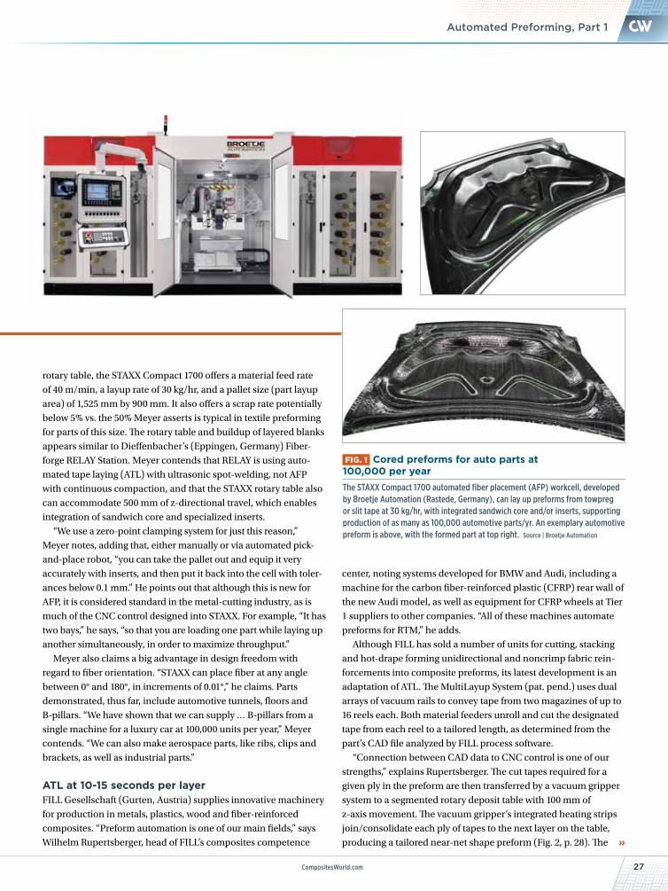
Enclosed automated fiber placement cellIn 2015, Broetje Automation (Rastede, Germany), a supplier
of specialized production systems (e.g., handling, preforming,
assembly, machining) for the aerospace industry, introduced its
STAXX Compact 1700 automated AFP workcell for near-net shape
preforms (Fig. 1, p. 27). “When we started development, there
were many companies focused on automated fiber placement for
aerospace,” says Dr. Matthias Meyer, VP of Broetje Automation’s
subsidiary BA Composites GmbH (Grenzach-Wyhlen, Germany),
“So we focused on automotive and industrial parts, and also on
using a low-cost input material — towpreg.” This also motivated
the unit’s design as an enclosed, climate-controlled cell with a
footprint of 3m wide by 6.5m long by 3m high — a compact system
that could be put into production quickly in practically any facility.
Meyer, who defines towpreg as a carbon fiber roving impreg-
nated with a typically epoxy matrix, notes that the STAXX also can
process dry fiber with binder applied ready for subsequent liquid
molding, or a thermoplastic product, which, after preforming, is
simply thermoformed into finished parts. (STAXX also can process
slit prepreg tape because it can remove the backing film, but its use
increases cost because it requires post-prepreg slitting operations.)
Comprising two magazines, each housing 16 spools for towpreg
feed, an AFP head with a compact clamp/cut/restart unit and a
By Ginger Gardiner / Senior Editor
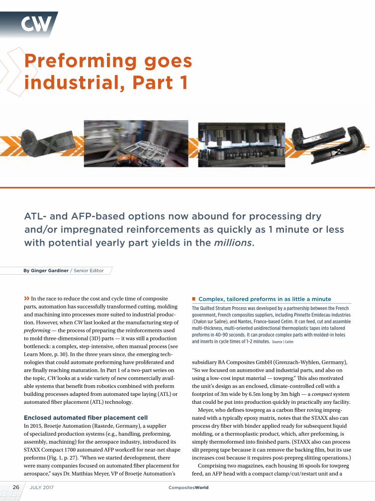
Complex, tailored preforms in as little a minuteThe Quilted Stratum Process was developed by a partnership between the French government, French composites suppliers, including Pinnette Emidecau Industries (Chalon sur Saône), and Nantes, France-based Cetim. It can feed, cut and assemble multi-thickness, multi-oriented unidirectional thermoplastic tapes into tailored preforms in 40-90 seconds. It can produce complex parts with molded-in holes and inserts in cycle times of 1-2 minutes. Source | Cetim
27CompositesWorld.com
NEWSAutomated Preforming, Part 1
rotary table, the STAXX Compact 1700 offers a material feed rate
of 40 m/min, a layup rate of 30 kg/hr, and a pallet size (part layup
area) of 1,525 mm by 900 mm. It also offers a scrap rate potentially
below 5% vs. the 50% Meyer asserts is typical in textile preforming
for parts of this size. The rotary table and buildup of layered blanks
appears similar to Dieffenbacher’s (Eppingen, Germany) Fiber-
forge RELAY Station. Meyer contends that RELAY is using auto-
mated tape laying (ATL) with ultrasonic spot-welding, not AFP
with continuous compaction, and that the STAXX rotary table also
can accommodate 500 mm of z-directional travel, which enables
integration of sandwich core and specialized inserts.
“We use a zero-point clamping system for just this reason,”
Meyer notes, adding that, either manually or via automated pick-
and-place robot, “you can take the pallet out and equip it very
accurately with inserts, and then put it back into the cell with toler-
ances below 0.1 mm.” He points out that although this is new for
AFP, it is considered standard in the metal-cutting industry, as is
much of the CNC control designed into STAXX. For example, “It has
two bays,” he says, “so that you are loading one part while laying up
another simultaneously, in order to maximize throughput.”
Meyer also claims a big advantage in design freedom with
regard to fiber orientation. “STAXX can place fiber at any angle
between 0° and 180°, in increments of 0.01°,” he claims. Parts
demonstrated, thus far, include automotive tunnels, floors and
B-pillars. “We have shown that we can supply … B-pillars from a
single machine for a luxury car at 100,000 units per year,” Meyer
contends. “We can also make aerospace parts, like ribs, clips and
brackets, as well as industrial parts.”
ATL at 10-15 seconds per layerFILL Gesellschaft (Gurten, Austria) supplies innovative machinery
for production in metals, plastics, wood and fiber-reinforced
composites. “Preform automation is one of our main fields,” says
Wilhelm Rupertsberger, head of FILL’s composites competence
center, noting systems developed for BMW and Audi, including a
machine for the carbon fiber-reinforced plastic (CFRP) rear wall of
the new Audi model, as well as equipment for CFRP wheels at Tier
1 suppliers to other companies. “All of these machines automate
preforms for RTM,” he adds.
Although FILL has sold a number of units for cutting, stacking
and hot-drape forming unidirectional and noncrimp fabric rein-
forcements into composite preforms, its latest development is an
adaptation of ATL. The MultiLayup System (pat. pend.) uses dual
arrays of vacuum rails to convey tape from two magazines of up to
16 reels each. Both material feeders unroll and cut the designated
tape from each reel to a tailored length, as determined from the
part’s CAD file analyzed by FILL process software.
“Connection between CAD data to CNC control is one of our
strengths,” explains Rupertsberger. The cut tapes required for a
given ply in the preform are then transferred by a vacuum gripper
system to a segmented rotary deposit table with 100 mm of
z-axis movement. The vacuum gripper’s integrated heating strips
join/consolidate each ply of tapes to the next layer on the table,
producing a tailored near-net shape preform (Fig. 2, p. 28). The
FIG. 1 Cored preforms for auto parts at 100,000 per year The STAXX Compact 1700 automated fiber placement (AFP) workcell, developed by Broetje Automation (Rastede, Germany), can lay up preforms from towpreg or slit tape at 30 kg/hr, with integrated sandwich core and/or inserts, supporting production of as many as 100,000 automotive parts/yr. An exemplary automotive preform is above, with the formed part at top right. Source | Broetje Automation
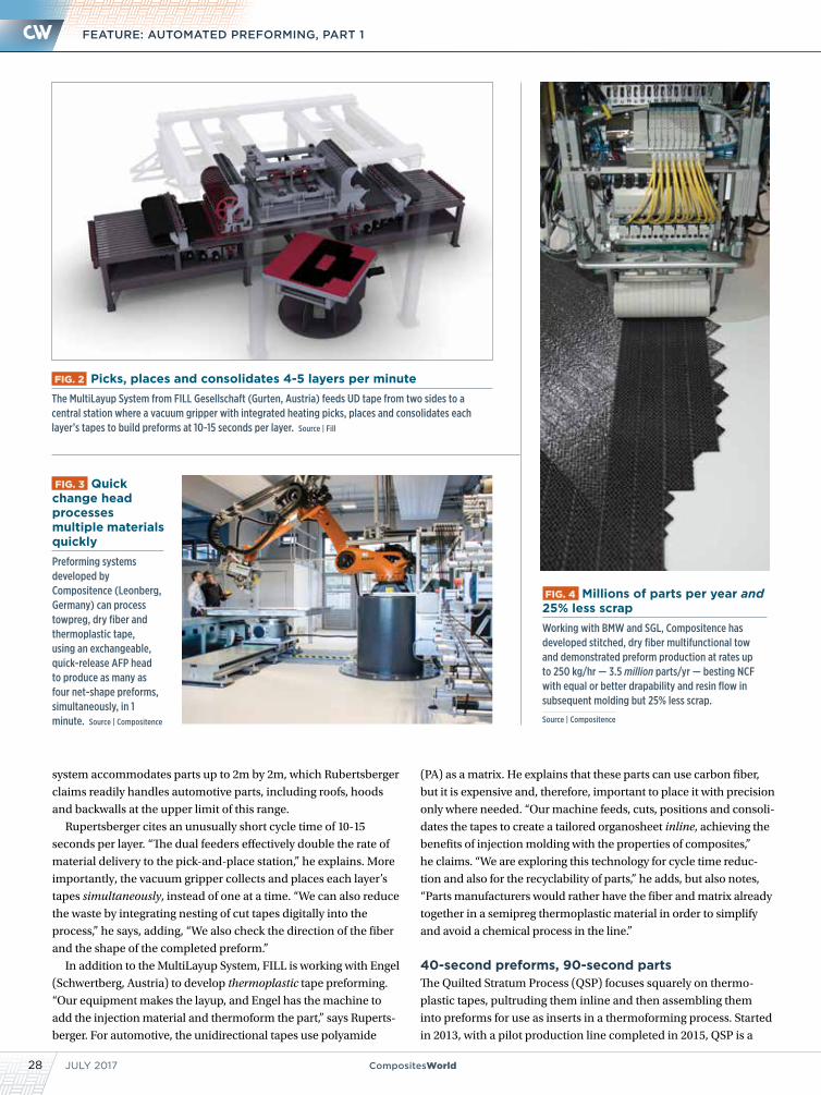
JULY 201728 CompositesWorld
FEATURE: AUTOMATED PREFORMING, PART 1
system accommodates parts up to 2m by 2m, which Rubertsberger
claims readily handles automotive parts, including roofs, hoods
and backwalls at the upper limit of this range.
Rupertsberger cites an unusually short cycle time of 10-15
seconds per layer. “The dual feeders effectively double the rate of
material delivery to the pick-and-place station,” he explains. More
importantly, the vacuum gripper collects and places each layer’s
tapes simultaneously, instead of one at a time. “We can also reduce
the waste by integrating nesting of cut tapes digitally into the
process,” he says, adding, “We also check the direction of the fiber
and the shape of the completed preform.”
In addition to the MultiLayup System, FILL is working with Engel
(Schwertberg, Austria) to develop thermoplastic tape preforming.
“Our equipment makes the layup, and Engel has the machine to
add the injection material and thermoform the part,” says Ruperts-
berger. For automotive, the unidirectional tapes use polyamide
(PA) as a matrix. He explains that these parts can use carbon fiber,
but it is expensive and, therefore, important to place it with precision
only where needed. “Our machine feeds, cuts, positions and consoli-
dates the tapes to create a tailored organosheet inline, achieving the
benefits of injection molding with the properties of composites,”
he claims. “We are exploring this technology for cycle time reduc-
tion and also for the recyclability of parts,” he adds, but also notes,
“Parts manufacturers would rather have the fiber and matrix already
together in a semipreg thermoplastic material in order to simplify
and avoid a chemical process in the line.”
40-second preforms, 90-second partsThe Quilted Stratum Process (QSP) focuses squarely on thermo-
plastic tapes, pultruding them inline and then assembling them
into preforms for use as inserts in a thermoforming process. Started
in 2013, with a pilot production line completed in 2015, QSP is a
FIG. 2 Picks, places and consolidates 4-5 layers per minuteThe MultiLayup System from FILL Gesellschaft (Gurten, Austria) feeds UD tape from two sides to a central station where a vacuum gripper with integrated heating picks, places and consolidates each layer’s tapes to build preforms at 10-15 seconds per layer. Source | Fill
FIG. 4 Millions of parts per year and 25% less scrapWorking with BMW and SGL, Compositence has developed stitched, dry fiber multifunctional tow and demonstrated preform production at rates up to 250 kg/hr — 3.5 million parts/yr — besting NCF with equal or better drapability and resin flow in subsequent molding but 25% less scrap.
Source | Compositence
FIG. 3 Quick change head processes multiple materials quicklyPreforming systems developed by Compositence (Leonberg, Germany) can process towpreg, dry fiber and thermoplastic tape, using an exchangeable, quick-release AFP head to produce as many as four net-shape preforms, simultaneously, in 1 minute. Source | Compositence
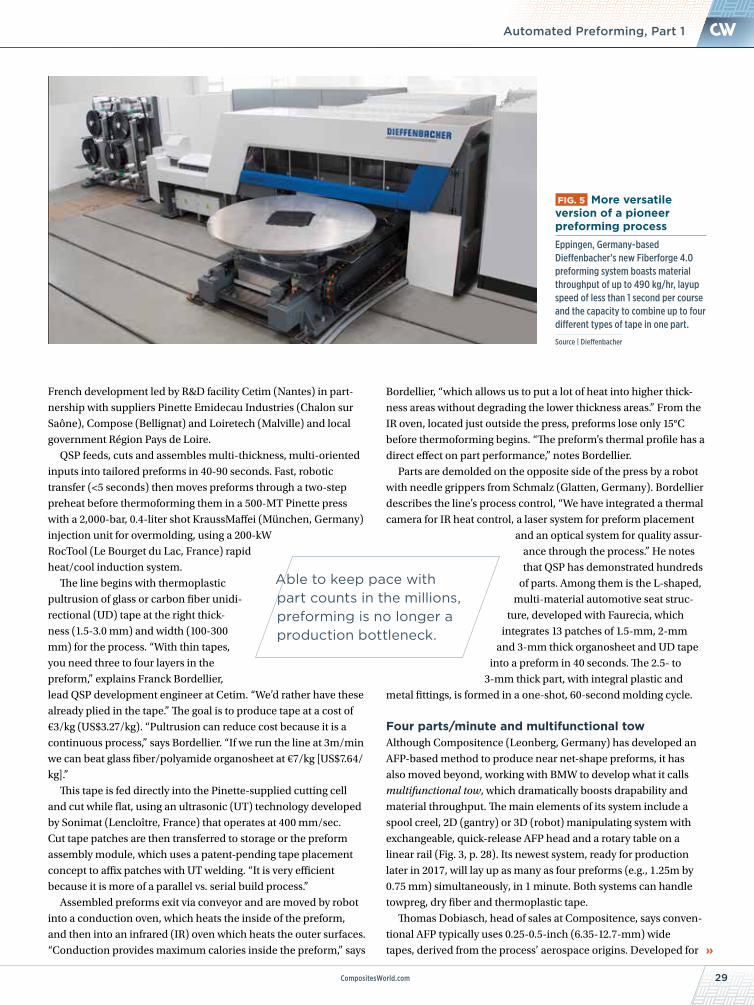
29CompositesWorld.com
NEWS
French development led by R&D facility Cetim (Nantes) in part-
nership with suppliers Pinette Emidecau Industries (Chalon sur
Saône), Compose (Bellignat) and Loiretech (Malville) and local
government Région Pays de Loire.
QSP feeds, cuts and assembles multi-thickness, multi-oriented
inputs into tailored preforms in 40-90 seconds. Fast, robotic
transfer (<5 seconds) then moves preforms through a two-step
preheat before thermoforming them in a 500-MT Pinette press
with a 2,000-bar, 0.4-liter shot KraussMaffei (München, Germany)
injection unit for overmolding, using a 200-kW
RocTool (Le Bourget du Lac, France) rapid
heat/cool induction system.
The line begins with thermoplastic
pultrusion of glass or carbon fiber unidi-
rectional (UD) tape at the right thick-
ness (1.5-3.0 mm) and width (100-300
mm) for the process. “With thin tapes,
you need three to four layers in the
preform,” explains Franck Bordellier,
lead QSP development engineer at Cetim. “We’d rather have these
already plied in the tape.” The goal is to produce tape at a cost of
€3/kg (US$3.27/kg). “Pultrusion can reduce cost because it is a
continuous process,” says Bordellier. “If we run the line at 3m/min
we can beat glass fiber/polyamide organosheet at €7/kg [US$7.64/
kg].”
This tape is fed directly into the Pinette-supplied cutting cell
and cut while flat, using an ultrasonic (UT) technology developed
by Sonimat (Lencloître, France) that operates at 400 mm/sec.
Cut tape patches are then transferred to storage or the preform
assembly module, which uses a patent-pending tape placement
concept to affix patches with UT welding. “It is very efficient
because it is more of a parallel vs. serial build process.”
Assembled preforms exit via conveyor and are moved by robot
into a conduction oven, which heats the inside of the preform,
and then into an infrared (IR) oven which heats the outer surfaces.
“Conduction provides maximum calories inside the preform,” says
Bordellier, “which allows us to put a lot of heat into higher thick-
ness areas without degrading the lower thickness areas.” From the
IR oven, located just outside the press, preforms lose only 15°C
before thermoforming begins. “The preform’s thermal profile has a
direct effect on part performance,” notes Bordellier.
Parts are demolded on the opposite side of the press by a robot
with needle grippers from Schmalz (Glatten, Germany). Bordellier
describes the line’s process control, “We have integrated a thermal
camera for IR heat control, a laser system for preform placement
and an optical system for quality assur-
ance through the process.” He notes
that QSP has demonstrated hundreds
of parts. Among them is the L-shaped,
multi-material automotive seat struc-
ture, developed with Faurecia, which
integrates 13 patches of 1.5-mm, 2-mm
and 3-mm thick organosheet and UD tape
into a preform in 40 seconds. The 2.5- to
3-mm thick part, with integral plastic and
metal fittings, is formed in a one-shot, 60-second molding cycle.
Four parts/minute and multifunctional towAlthough Compositence (Leonberg, Germany) has developed an
AFP-based method to produce near net-shape preforms, it has
also moved beyond, working with BMW to develop what it calls
multifunctional tow, which dramatically boosts drapability and
material throughput. The main elements of its system include a
spool creel, 2D (gantry) or 3D (robot) manipulating system with
exchangeable, quick-release AFP head and a rotary table on a
linear rail (Fig. 3, p. 28). Its newest system, ready for production
later in 2017, will lay up as many as four preforms (e.g., 1.25m by
0.75 mm) simultaneously, in 1 minute. Both systems can handle
towpreg, dry fiber and thermoplastic tape.
Thomas Dobiasch, head of sales at Compositence, says conven-
tional AFP typically uses 0.25-0.5-inch (6.35-12.7-mm) wide
tapes, derived from the process’ aerospace origins. Developed for
FIG. 5 More versatile version of a pioneer preforming process Eppingen, Germany-based Dieffenbacher’s new Fiberforge 4.0 preforming system boasts material throughput of up to 490 kg/hr, layup speed of less than 1 second per course and the capacity to combine up to four different types of tape in one part.
Source | Dieffenbacher
Automated Preforming, Part 1
Able to keep pace with part counts in the millions, preforming is no longer a production bottleneck.
JULY 201730 CompositesWorld
FEATURE: AUTOMATED PREFORMING, PART 1
automotive parts, the Compositence system uses tapes ≥12 mm
wide with 150-600 g/m2 fiber areal weight because, says Dobiasch,
“placement of narrow materials takes too long. For us, the speed
of the preform layup must be in the same range as the molding
machines, which for injection molding is 1 minute.” However, he
cautions, “Wide tapes
can produce more waste
for certain types of parts.
You must tailor your
process for the part you
are making.”
In pursuit of speed,
Compositence has
patented its edge
fixation technology
for AFP. “We fix the
fibers only at the begin-
ning and end of place-
ment,” says Dobiasch,
explaining that the
AFP head lifts slightly
up to fly freely, “accel-
erating across the layup in between, which speeds up produc-
tivity.” However, this edge fixation technique cannot be used with
towpreg, because it requires continuous compaction to avoid
trapping air in the layup.
Another key driver in preforming productivity is drapability. “Our
draping capability must be the same as noncrimp fabric [NCF] or
better,” notes Dobiasch. Since 2010, Compositence has worked on
AFP preforming with BMW (Munich, Germany) and SGL Group
(Wiesbaden, Germany). “With them, we have developed what we
call multifunctional tow, where multiple rovings are fixed together
with a kind of textile process,” he explains (Fig. 4, p. 28). The stitching
binds the tows to maintain precise width — typically 46 mm for dry
fiber — and also aids resin flow vertically through the fibers, crucial
in the next step, either resin injection or infusion.
“The fibers are not blocked from moving layer to layer as they
are in stitched fabric,” Dobiasch explains, “so drapability is very
good and confirmed by BMW as being the same or better than NCF.
They have also verified the improved resin flow.” He concedes the
material does require more time and cost to produce vs. towpreg,
“but it is better to give the material some functions, and you then get
cash back during the processing via less scrap and better cycle time
in wet compression molding and RTM.”
Dobiasch claims a 25% reduction in scrap vs. NCF due to AFP’s
net shaping ability compared to cutting waste with fabric. He adds,
“We have also demonstrated with BMW that we can preform 3.5
million parts per year on one machine with an output of 250 kg/hr.”
Back to the future, Fiberforge 4.0The original automated tape/fiber preforming process was the
Fiberforge RELAY Station, mentioned earlier, which CW reported
Read this article online | short.compositesworld.com/PreformPt1
CW’s 2013 coverage of this subject, “Structural preform technologies emerge from the shadows,” offers a good preforming primer on preforming and discusses a variety of early automation efforts, including the Dieffenbacher PreformCenter | short.compositesworld.com/Mqzr7Fg7
Read CW’s earliest coverage of the Fiberforge RELAY station online in “Tailored carbon fiber blanks set to move into steel stamping arena” | short.compositesworld.com/LvFR7nP1
Walton Process Technologies, Inc.
Best Customer Service in The Industrywww.autoclaves.com
Mansfield TX 682-518-9002
Service/Repair
Retrofit/Relocate
Autoclaves
Bond Presses
Batch ProcessControls
Ovens
Parts
31CompositesWorld.com
NEWS
We create chemistrythat makes countless products love added performance
BASF high performance polyurethanes and engineering
plastics bring extraordinary innovation to everyday life.
These breakthrough materials make vehicles lighter and
more fuel efficient, buildings and infrastructure more durable
and energy efficient, manufacturing process and products
more efficient, and a myriad of consumer dramatically
better. Big ideas. Small environmental footprint.
Because at BASF, we create chemistry.
www.performance-materials.basf.us
on as early as 2004. A spin-off from high
mileage/low-weight automotive develop-
ment, it made its own tapes from large-
tow carbon fiber or glass rovings and
melted thermoplastic pellets (e.g., nylon),
orienting the fiber into a semi-consoli-
dated sheet, or tailored blank, which was
then heated and pressed into a composite
part. In 2008, it produced a unidirectional
glass/polyethylene military backpack
frame with integrated ribs in 70 seconds,
with reported production of 20,000 units.
Although Fiberforge was liquidated in
2013, Dieffenbacher (Eppingen, Germany)
acquired the RELAY technology and has
continued its development. Dieffenbach-
er’s Fiberforge RELAY Station, capable of
2m-by-2m parts and laydown rates to 150
kg/hr in 2014, has evolved into Fiberforge
4.0 (Fig. 5, p. 29). This more recent devel-
opment boasts material throughput of
490 kg/hr with a layup time of less than 1
second per course, and it has the ability to
combine as many as four types of tape in
one part. Further, version 4.0 reportedly
can interface with other Dieffenbacher
automated systems to produce more than
1 million parts/yr from a single production
line. “Fiberforge 4.0 is a game changer,”
contends Dieffenbacher’s director of
technology and business development
Matthias Graf, “and we expect that it will
bring a breakthrough for composites in the
automobile industry.”
More to comeThe examples mentioned here are not
exhaustive. Other early preforming
pioneers, such as Coriolis Composites
(Queven, France), also are at work on
faster evolutions of AFP for automotive
preforms, including glass fiber/polyamide
prepreg tape loops, which are overmolded
to produce composite engine mounts. And
new players continue to emerge. Voith
Composites (Garching bei München,
Germany), for example, launched its
Voith Roving Applicator at JEC World 2017
(March 14-16, Paris, France).
More detailed discussions of additional
players and other preforming processes,
plus news about standardized drapability
testing, preform simulation software and
specific solutions for aerospace and wind
energy structures, can be found online
in the CW Blog Automated
Preforming series | short.compos-itesworld.com/AutoPFBlog.
All that to say this: Given
the ongoing activity — already
commercial and potential — it’s
already clear that preforming is
unlikely to remain a composites production bottleneck. And in Part 2, CW will explore
new solutions for forming fabrics, 3D and continuous preforming processes and the
latest in tailored fiber placement (TFP) technology.
CW senior editor Ginger Gardiner has an engineering/materials background and more than 20 years of experience in the composites industry. [email protected]
Automated Preforming, Part 1
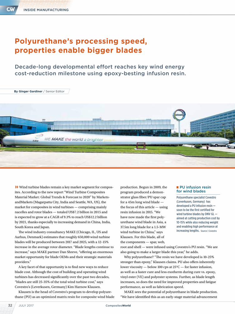
JULY 201732 CompositesWorld
INSIDE MANUFACTURING
Decade-long developmental effort reaches key wind energy cost-reduction milestone using epoxy-besting infusion resin.
» Wind turbine blades remain a key market segment for compos-
ites. According to the new report “Wind Turbine Composites
Material Market: Global Trends & Forecast to 2020” by Markets-
andMarkets (Magarpatta City, India and Seattle, WA, US), the
market for composites in wind turbines — comprising mainly
nacelles and rotor blades — totaled US$7.2 billion in 2015 and
is expected to grow at a CAGR of 9.3% to reach US$12.2 billion
by 2021, thanks especially to increasing demand in China, India,
South Korea and Japan.
The wind industry consultancy MAKE (Chicago, IL, US and
Aarhus, Denmark) estimates that roughly 650,000 wind turbine
blades will be produced between 2017 and 2025, with a 12-15%
increase in the average rotor diameter. “Blade lengths continue to
increase,” says MAKE partner Dan Shreve, “offering an enormous
market opportunity for blade OEMs and their strategic materials
providers.”
A key facet of that opportunity is to find new ways to reduce
blade cost. Although the cost of building and operating wind
turbines has decreased significantly over the past two decades,
“blades are still 25-35% of the total wind turbine cost,” says
Covestro’s (Leverkusen, Germany) Kim Harnow Klausen.
Klausen is the head of Covestro’s program to develop polyure-
thane (PU) as an optimized matrix resin for composite wind blade
production. Begun in 2009, the
program produced a demon-
strator glass fiber/PU spar cap
for a 45m long wind blade —
the focus of this article — using
resin infusion in 2015. “We
have now made the first poly-
urethane wind blade in Asia, a
37.5m long blade for a 1.5-MW
wind turbine in China,” says
Klausen. For this blade, all of
the components — spar, web,
root and shell — were infused using Covestro’s PU resin. “We are
also going to make a larger blade this year,” he adds.
Why polyurethane? “The resin we have developed is 10-25%
stronger than epoxy,” Klausen claims. PU also offers inherently
lower viscosity — below 100 cps at 25°C — for faster infusion,
as well as a faster cure and less exotherm during cure vs. epoxy,
vinyl ester (VE) and polyester systems. Further, as blade length
increases, so does the need for improved properties and fatigue
performance, as well as fabrication speed.
MAKE sees the potential of polyurethane in blade production.
“We have identified this as an early-stage material advancement
Polyurethane’s processing speed, properties enable bigger blades
PU infusion resin for wind blades
Polyurethane specialist Covestro (Leverkusen, Germany) has developed a PU infusion resin — soon to be the first certified for wind turbine blades by DNV GL — aimed at cutting production cost by 10-15% while also reducing weight and enabling high performance at increasing lengths. Source | Covestro
By Ginger Gardiner / Senior Editor
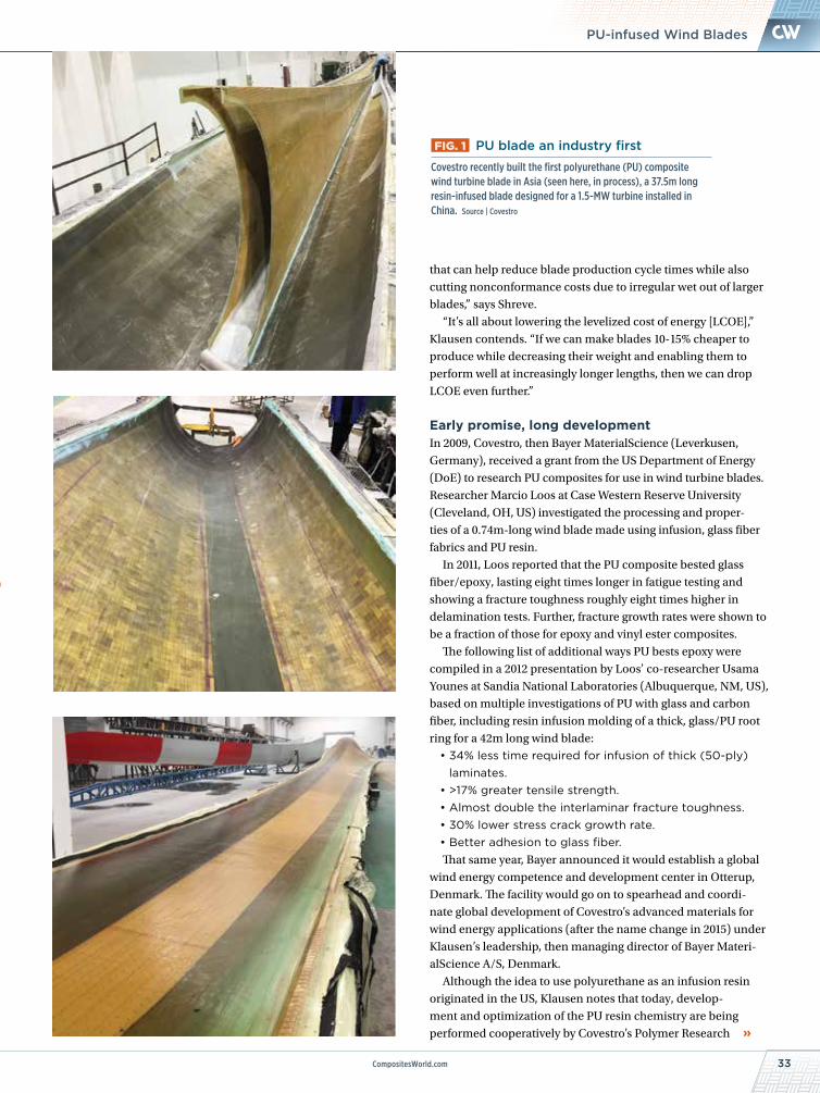
CompositesWorld.com 33
NEWS
that can help reduce blade production cycle times while also
cutting nonconformance costs due to irregular wet out of larger
blades,” says Shreve.
“It’s all about lowering the levelized cost of energy [LCOE],”
Klausen contends. “If we can make blades 10-15% cheaper to
produce while decreasing their weight and enabling them to
perform well at increasingly longer lengths, then we can drop
LCOE even further.”
Early promise, long developmentIn 2009, Covestro, then Bayer MaterialScience (Leverkusen,
Germany), received a grant from the US Department of Energy
(DoE) to research PU composites for use in wind turbine blades.
Researcher Marcio Loos at Case Western Reserve University
(Cleveland, OH, US) investigated the processing and proper-
ties of a 0.74m-long wind blade made using infusion, glass fiber
fabrics and PU resin.
In 2011, Loos reported that the PU composite bested glass
fiber/epoxy, lasting eight times longer in fatigue testing and
showing a fracture toughness roughly eight times higher in
delamination tests. Further, fracture growth rates were shown to
be a fraction of those for epoxy and vinyl ester composites.
The following list of additional ways PU bests epoxy were
compiled in a 2012 presentation by Loos’ co-researcher Usama
Younes at Sandia National Laboratories (Albuquerque, NM, US),
based on multiple investigations of PU with glass and carbon
fiber, including resin infusion molding of a thick, glass/PU root
ring for a 42m long wind blade:
• 34% less time required for infusion of thick (50-ply) laminates.
• >17% greater tensile strength.• Almost double the interlaminar fracture toughness.• 30% lower stress crack growth rate.• Better adhesion to glass fiber.That same year, Bayer announced it would establish a global
wind energy competence and development center in Otterup,
Denmark. The facility would go on to spearhead and coordi-
nate global development of Covestro’s advanced materials for
wind energy applications (after the name change in 2015) under
Klausen’s leadership, then managing director of Bayer Materi-
alScience A/S, Denmark.
Although the idea to use polyurethane as an infusion resin
originated in the US, Klausen notes that today, develop-
ment and optimization of the PU resin chemistry are being
performed cooperatively by Covestro’s Polymer Research
PU-infused Wind Blades
FIG. 1 PU blade an industry first
Covestro recently built the first polyurethane (PU) composite wind turbine blade in Asia (seen here, in process), a 37.5m long resin-infused blade designed for a 1.5-MW turbine installed in China. Source | Covestro
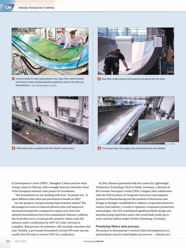
JULY 201734 CompositesWorld
INSIDE MANUFACTURING
In 2015, Klausen partnered with the Center for Lightweight
Production Technology (ZLP) in Stade, Germany, a division of
the German Aerospace Center (DLR, Cologne) that collaborates
with the DLR Institute of Composite Structures and Adaptive
Systems in Braunschweig and the Institute of Structures and
Design in Stuttgart. Established to enhance cooperation between
science and industry, it works to optimize composites production
technologies. The ZLP contributed significant blade design and
manufacturing experience and a 45m wind blade mold, previ-
ously used by turbine maker Nordex (Hamburg, Germany).
Finalizing fibers and processThe project to demonstrate Covestro’s latest developments in a
polyurethane resin for wind blades was now set — infusion of a
1 Covestro tested its latest polyurethane resin, glass fiber reinforcements and infusion setup, including injection equipment, prior to the spar cap demonstration. Source (all step photos) | Covestro
& Development Center (PRDC, Shanghai, China) and the wind
energy center in Otterup, with oversight from Jan Drescher, head
of the European infusion resin project in Leverkusen.
“The formulation we are working with now,” he points out, “is
quite different than what was presented at Sandia in 2012.”
Are the property and processing improvements similar? The
advantages in terms of reduced infusion time and improved
mechanical properties compared to epoxy and vinyl ester
infusion formulations have been maintained, Klausen confirms,
but he prefers not to reveal specific property values until this
infusion resin’s certification by DNV GL (Oslo, Norway) is
complete. That process, he estimates, will conclude sometime this
year. Notably, a previously formulated Covestro PU resin was the
world’s first PU resin to receive DNV GL certification.
3 Glass fiber unidirectional reinforcements are placed into the mold.
2 Mold release film is applied to the 45m blade’s mold surface. 4 The vacuum bag, resin supply lines and vacuum lines are installed.
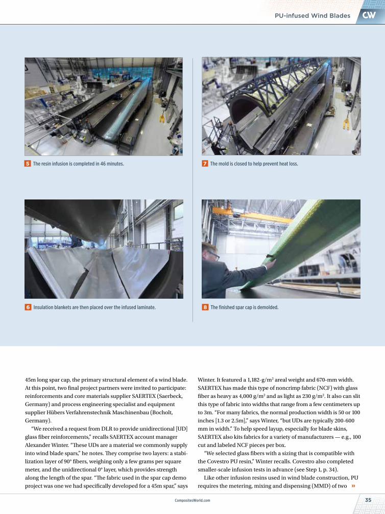
CompositesWorld.com 35
NEWSPU-infused Wind Blades
45m long spar cap, the primary structural element of a wind blade.
At this point, two final project partners were invited to participate:
reinforcements and core materials supplier SAERTEX (Saerbeck,
Germany) and process engineering specialist and equipment
supplier Hübers Verfahrenstechnik Maschinenbau (Bocholt,
Germany).
“We received a request from DLR to provide unidirectional [UD]
glass fiber reinforcements,” recalls SAERTEX account manager
Alexander Winter. “These UDs are a material we commonly supply
into wind blade spars,” he notes. They comprise two layers: a stabi-
lization layer of 90° fibers, weighing only a few grams per square
meter, and the unidirectional 0° layer, which provides strength
along the length of the spar. “The fabric used in the spar cap demo
project was one we had specifically developed for a 45m spar,” says
Winter. It featured a 1,182-g/m2 areal weight and 670-mm width.
SAERTEX has made this type of noncrimp fabric (NCF) with glass
fiber as heavy as 4,000 g/m2 and as light as 230 g/m2. It also can slit
this type of fabric into widths that range from a few centimeters up
to 3m. “For many fabrics, the normal production width is 50 or 100
inches [1.3 or 2.5m],” says Winter, “but UDs are typically 200-600
mm in width.” To help speed layup, especially for blade skins,
SAERTEX also kits fabrics for a variety of manufacturers — e.g., 100
cut and labeled NCF pieces per box.
“We selected glass fibers with a sizing that is compatible with
the Covestro PU resin,” Winter recalls. Covestro also completed
smaller-scale infusion tests in advance (see Step 1, p. 34).
Like other infusion resins used in wind blade construction, PU
requires the metering, mixing and dispensing (MMD) of two
5 The resin infusion is completed in 46 minutes. 7 The mold is closed to help prevent heat loss.
6 Insulation blankets are then placed over the infused laminate. 8 The finished spar cap is demolded.
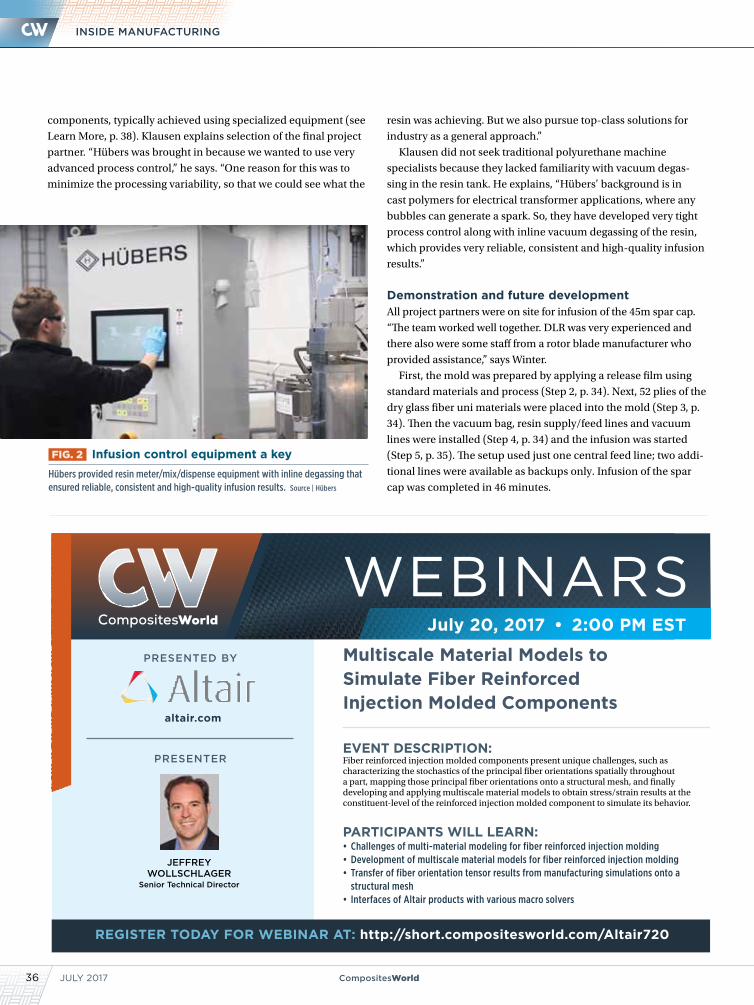
JULY 201736 CompositesWorld
INSIDE MANUFACTURING
resin was achieving. But we also pursue top-class solutions for
industry as a general approach.”
Klausen did not seek traditional polyurethane machine
specialists because they lacked familiarity with vacuum degas-
sing in the resin tank. He explains, “Hübers’ background is in
cast polymers for electrical transformer applications, where any
bubbles can generate a spark. So, they have developed very tight
process control along with inline vacuum degassing of the resin,
which provides very reliable, consistent and high-quality infusion
results.”
Demonstration and future developmentAll project partners were on site for infusion of the 45m spar cap.
“The team worked well together. DLR was very experienced and
there also were some staff from a rotor blade manufacturer who
provided assistance,” says Winter.
First, the mold was prepared by applying a release film using
standard materials and process (Step 2, p. 34). Next, 52 plies of the
dry glass fiber uni materials were placed into the mold (Step 3, p.
34). Then the vacuum bag, resin supply/feed lines and vacuum
lines were installed (Step 4, p. 34) and the infusion was started
(Step 5, p. 35). The setup used just one central feed line; two addi-
tional lines were available as backups only. Infusion of the spar
cap was completed in 46 minutes.
components, typically achieved using specialized equipment (see
Learn More, p. 38). Klausen explains selection of the final project
partner. “Hübers was brought in because we wanted to use very
advanced process control,” he says. “One reason for this was to
minimize the processing variability, so that we could see what the
FIG. 2 Infusion control equipment a keyHübers provided resin meter/mix/dispense equipment with inline degassing that ensured reliable, consistent and high-quality infusion results. Source | Hübers
PRESENTER
PRESENTED BY
altair.com
JEFFREY WOLLSCHLAGER
Senior Technical Director
EVENT DESCRIPTION: Fiber reinforced injection molded components present unique challenges, such as characterizing the stochastics of the principal fiber orientations spatially throughout a part, mapping those principal fiber orientations onto a structural mesh, and finally developing and applying multiscale material models to obtain stress/strain results at the constituent-level of the reinforced injection molded component to simulate its behavior.
PARTICIPANTS WILL LEARN: • Challenges of multi-material modeling for fiber reinforced injection molding• Development of multiscale material models for fiber reinforced injection molding• Transfer of fiber orientation tensor results from manufacturing simulations onto a
structural mesh• Interfaces of Altair products with various macro solvers
Multiscale Material Models to Simulate Fiber Reinforced Injection Molded Components
July 20, 2017 • 2:00 PM EST
REGISTER TODAY FOR WEBINAR AT: http://short.compositesworld.com/Altair720
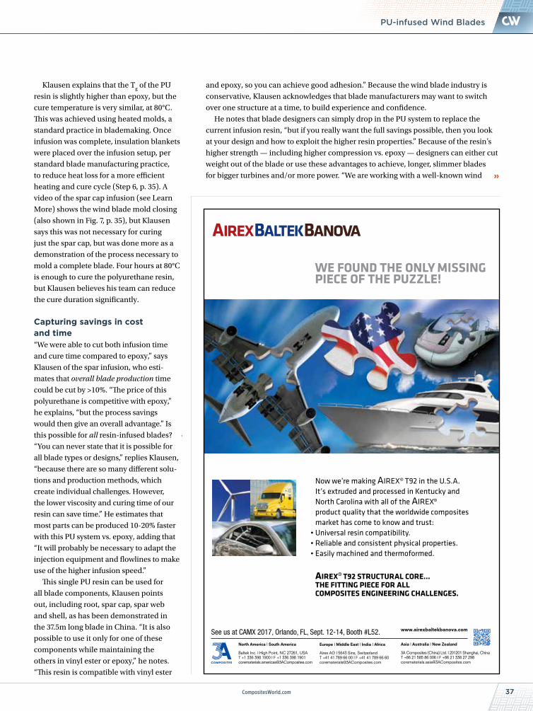
37CompositesWorld.com
NEWS
Klausen explains that the Tg of the PU
resin is slightly higher than epoxy, but the
cure temperature is very similar, at 80°C.
This was achieved using heated molds, a
standard practice in blademaking. Once
infusion was complete, insulation blankets
were placed over the infusion setup, per
standard blade manufacturing practice,
to reduce heat loss for a more efficient
heating and cure cycle (Step 6, p. 35). A
video of the spar cap infusion (see Learn
More) shows the wind blade mold closing
(also shown in Fig. 7, p. 35), but Klausen
says this was not necessary for curing
just the spar cap, but was done more as a
demonstration of the process necessary to
mold a complete blade. Four hours at 80°C
is enough to cure the polyurethane resin,
but Klausen believes his team can reduce
the cure duration significantly.
Capturing savings in cost and time“We were able to cut both infusion time
and cure time compared to epoxy,” says
Klausen of the spar infusion, who esti-
mates that overall blade production time
could be cut by >10%. “The price of this
polyurethane is competitive with epoxy,”
he explains, “but the process savings
would then give an overall advantage.” Is
this possible for all resin-infused blades?
“You can never state that it is possible for
all blade types or designs,” replies Klausen,
“because there are so many different solu-
tions and production methods, which
create individual challenges. However,
the lower viscosity and curing time of our
resin can save time.” He estimates that
most parts can be produced 10-20% faster
with this PU system vs. epoxy, adding that
“It will probably be necessary to adapt the
injection equipment and flowlines to make
use of the higher infusion speed.”
This single PU resin can be used for
all blade components, Klausen points
out, including root, spar cap, spar web
and shell, as has been demonstrated in
the 37.5m long blade in China. “It is also
possible to use it only for one of these
components while maintaining the
others in vinyl ester or epoxy,” he notes.
“This resin is compatible with vinyl ester
PU-infused Wind Blades
WE FOUND THE ONLYMISSINGPIECE OF THE PUZZLE!
Now we’re making AIREX® T92 in the U.S.A.It’s extruded and processed in Kentucky andNorth Carolina with all of the AIREX®product quality that the worldwide compositesmarket has come to know and trust:• Universal resin compatibility.• Reliable and consistent physical properties.• Easily machined and thermoformed.
AIREX®T92 STRUCTURAL CORE...THE FITTING PIECE FOR ALLCOMPOSITES ENGINEERING CHALLENGES.
www.airexbaltekbanova.com
North America I South America
Baltek Inc. I High Point, NC 27261, USAT +1 336 398 1900 I F +1 336 398 [email protected]
Europe I Middle East I India I Africa
Airex AG I 5643 Sins, SwitzerlandT +41 41 789 66 00 I F +41 41 789 66 [email protected]
Asia I Australia I New Zealand
3A Composites (China) Ltd. I 201201 Shanghai, ChinaT +86 21 585 86 006 I F +86 21 338 27 [email protected]
See us at CAMX 2017, Orlando, FL, Sept. 12-14, Booth #L52.
and epoxy, so you can achieve good adhesion.” Because the wind blade industry is
conservative, Klausen acknowledges that blade manufacturers may want to switch
over one structure at a time, to build experience and confidence.
He notes that blade designers can simply drop in the PU system to replace the
current infusion resin, “but if you really want the full savings possible, then you look
at your design and how to exploit the higher resin properties.” Because of the resin’s
higher strength — including higher compression vs. epoxy — designers can either cut
weight out of the blade or use these advantages to achieve, longer, slimmer blades
for bigger turbines and/or more power. “We are working with a well-known wind
JULY 201738 CompositesWorld
INSIDE MANUFACTURING
WTF
yomingest
ixturesINC.
• Over 40 types of fixtures in stock, ready to be shipped. • Expert consultation with Dr. Adams • Email or call today to discuss your fixture and custom design needs.
Three and Four Point Short Beam FixtureASTM D 790, D 6272,
D 7264, D 2344
2960 E. Millcreek Canyon RoadSalt Lake City, UT 84109
Phone (801) 484.5055Fax (801) 484.6008
email: [email protected]
Dr. Donald F. AdamsPresident50 years of Composite Testing Experience
FLEXURE FIXTURES FOR EVERY SPECIMEN SIZE
We provide quotes for a variety of grips, fixtures, and jigs. We carry over 40 types of fixtures in stock, available for immediate delivery.
Email or call us today. We look forward to hearing from you.
Three and Four Point FlexureASTM D 790,
D 6272, D 7264
Long Beam Flexure Fixture
w/Alignment Rods and Bearings
ASTM C 393, D 7249
Reversed Cycle Flexural Fatigue
Miniature Flexure Fixture
blade design firm now, WINDnovation
[Berlin, Germany], to calculate the design
advantages of using this polyurethane resin.”
Klausen believes that even designers who
prefer to take the drop-in approach one
structure at a time on their current produc-
tion blades will nevertheless redesign their next-generation blades to fully capture the
PU property benefits. “This is why we are fully documenting the design possibilities with
WINDnovation,” he adds.
“We will also move forward with
further demonstrating the resin in larger
blades,” says Klausen. The current plan
is to build further full-blade prototypes
and test them extensively during the
next year. “Our goal is to provide test
results that will be accepted interna-
tionally,” he notes, “so we will choose
a well-recognized test facility for this
demonstration.”
There is also the possibility to do
more demonstrations with DLR. For its
part, SAERTEX would like to partici-
pate in larger blade demonstrations
using its new core material, SAERfoam.
“This would replace balsa wood core
for a 25% weight reduction, depending
on the blade design,” says Winter, who
sees applications for the new core
beyond wind, such as in marine and
construction/infrastructure.
Klausen also sees opportunities
beyond wind for Covestro’s new PU
infusion system, but for now, the focus
is on finishing the development for
rotor blades. “We will spend 2017 docu-
menting all of the resin and composite
mechanical properties as well as the
aging properties,” he observes. “We will
also do a lot of health, safety and envi-
ronmental testing and documentation.”
Klausen explains that Covestro has
many internal standards that exceed,
sometimes significantly, others in the
industry, such as DNV GL. “We must
fulfill all of these first — for example,
performing grinding on cured compos-
ites with this resin, collecting the dust
and analyzing it,” he notes. “We will then
be able to present a complete package
to the end-users.” In the meantime, his
team is finalizing further demonstra-
tions, and aiming for final commercial-
ization in 2018.
CW senior editor Ginger Gardiner has an engineering/materials background and more than 20 years of experience in the composites industry. [email protected]
Read this article online | short.compositesworld.com/PUBigBlade
Read more about meter/mix/dispense equipment online | short.compositesworld.com/MMD
ADVERTISING INDEX
39
CALENDAR
CompositesWorld.com
Composites EventsJuly 4-7, 2017 — Bologna, Italy3rd International Conference on Mechanics of
Composites (MechComp 2017)events.unibo.it/mechcomp3
July 16-22, 2017 — Rome, ItalyICCE-25, 25th Annual International Conference on
Composites and Nanoicce-nano.org
July 17-20, 2017 — Ottawa, ON, CanadaCANCOM 2017cancom2017.org
July 24-30, 2017 — Oshkosh, WI, US2017 EAA AirVentureeaa.org/en/airventure
July 25-27, 2017 — Dayton, OH, USIACMI Summer Members Meetingiacmi.org/ohiomembersmeeting
Aug. 20-25, 2017 — Xi’an, ChinaICCM21 – 21st International Conference on Composite
Materialsiccm21.org
Aug. 22-24, 2017 — Detroit, MI, US6th Global Automotive Lightweight Materials
Congress 2017global-automotive-lightweight-materials-detroit.com
Sept. 6-8, 2017 — Novi, MI, USSPE Automotive Composites Conference and
Exhibition (ACCE)speautomotive.com/acce-conference
Sept. 11-14, 2017 — Orlando, FL, USCAMX (Composites and Advanced Materials Expo) 2017thecamx.org
Sept. 12-15, 2017 — Husum, GermanyHUSUM Wind 2017husumwind.com/husumwind/en
Sept. 13-15, 2017 — Nagoya, Aichi, JapanICOLSE – 2017 International Conference on
Lightning and Static Electricityicolse2017.org
Sept. 18-20, 2017 — Toulouse, FranceSpeedNews 18th Annual Aviation Industry Suppliers
Conference in Toulouse speednews.com/aviation-industry-suppliers-conference-in-toulouse
Sept. 19-21, 2017 — Tampa, FL, USIBEX 2017 ibexshow.com/show-info
Sept. 19-21, 2017 — Stuttgart, GermanyComposites Europe 2017composites-europe.com
Sept. 19-23, 2017 — Vancouver, BC, Canada39th IABSE Symposium: Vancouver 2017iabse.org
Oct. 4-5, 2017 — Los Angeles, CA, USSpeedNews 22nd Annual Business & General Aviation
Industry Suppliers Conferencespeednews.com/business-and-general-aviation-industry-suppliers-conference
Oct. 5-7, 2017 — Istanbul, Turkey TURK Kompozit 2017 Composites Summit Turkeywww.turk-kompozit.org/en/home
Oct. 10-12, 2017 — Knoxville, TN, US Additive Manufacturing Conference 2017additiveconference.com
Oct. 17-19, 2017 — Wichita, KS, USASIDIC 2017: Aerospace Structural Impact Dynamics
International Conferenceasidiconference.org
Oct. 23-25, 2017 — West Lafayette, IN, US 32nd Annual American Society for Composites
Technical Conferencecdmhub.org/groups/asc2017
Nov. 1-3, 2017 — Seoul, Republic of Korea JEC Asia 2017jeccomposites.com/events/jec-asia-2017
Nov. 15-16, 2017 — Madrid, SpainComposite Spaincompositespain.com/en/default.html
Nov. 14-16, 2017 — Stuttgart, GermanySAMPE Conference 17 Stuttgartsampe-europe.org/conferences/conference-2017-stuttgart
Nov. 28-30, 2017 — Charleston, SC, USCompositesWorld's Carbon Fiber 2017carbonfiberevent.com
INTERNATIONAL INC. EUROPE Sarl ASIA LTDADVDVD ANCED MVANCED MV ATERIATERIA ALS LS L LTDLTDL
Benefi ts:• Save time with fewer
materials to cut and position.
• Improve part quality with simplifi ed process.
• Improve surface fi nish with fl atter materials.
• Reduce cost with less scrap and rework.
PRODUCT SPOTLIGHTPRODUCT SPOTLIGHTPRODUCT SPOTLIGHTPRODUCT SPOTLIGHTPRODUCT SPOTLIGHTPRODUCT SPOTLIGHTPRODUCT SPOTLIGHTPRODUCT SPOTLIGHTPRODUCT SPOTLIGHTPRODUCT SPOTLIGHTPRODUCT SPOTLIGHTPRODUCT SPOTLIGHTPRODUCT SPOTLIGHTPRODUCT SPOTLIGHTPRODUCT SPOTLIGHTPRODUCT SPOTLIGHTPRODUCT SPOTLIGHTPRODUCT SPOTLIGHTPRODUCT SPOTLIGHTPRODUCT SPOTLIGHTPRODUCT SPOTLIGHTPRODUCT SPOTLIGHTPRODUCT SPOTLIGHTPRODUCT SPOTLIGHT
Stretchlease®
Combination vacuum bag materials with Release Film, Breather, and/or Peel Ply bonded
into a multi-function laminate
Wrightlon® 5200 Release Film and Airweave® Breather bonded together
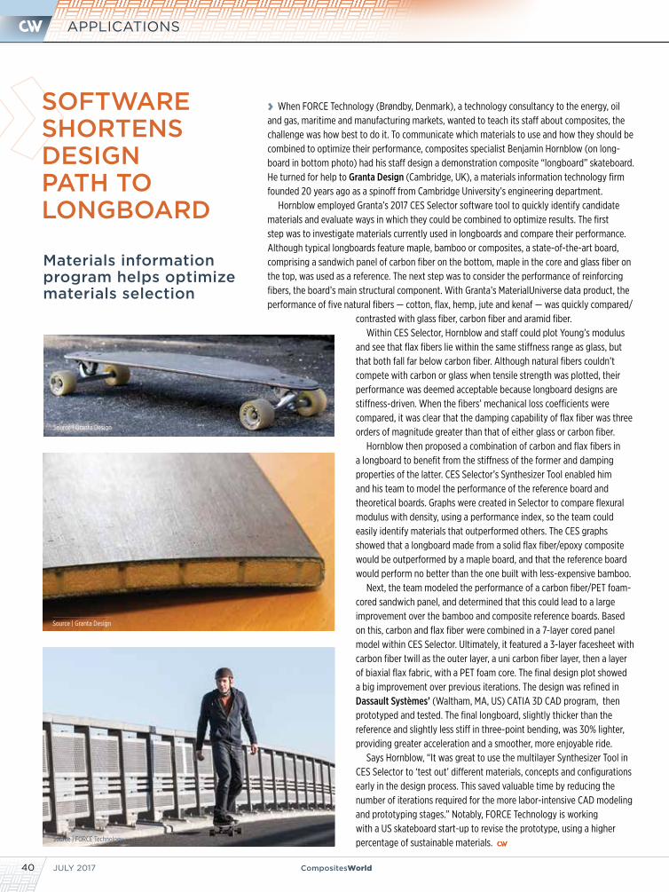
JULY 201740 CompositesWorld
APPLICATIONS
Materials information program helps optimize materials selection
› When FORCE Technology (Brøndby, Denmark), a technology consultancy to the energy, oil and gas, maritime and manufacturing markets, wanted to teach its staff about composites, the challenge was how best to do it. To communicate which materials to use and how they should be combined to optimize their performance, composites specialist Benjamin Hornblow (on long-board in bottom photo) had his staff design a demonstration composite “longboard” skateboard. He turned for help to Granta Design (Cambridge, UK), a materials information technology firm founded 20 years ago as a spinoff from Cambridge University’s engineering department.
Hornblow employed Granta’s 2017 CES Selector software tool to quickly identify candidate materials and evaluate ways in which they could be combined to optimize results. The first step was to investigate materials currently used in longboards and compare their performance. Although typical longboards feature maple, bamboo or composites, a state-of-the-art board, comprising a sandwich panel of carbon fiber on the bottom, maple in the core and glass fiber on the top, was used as a reference. The next step was to consider the performance of reinforcing fibers, the board’s main structural component. With Granta’s MaterialUniverse data product, the performance of five natural fibers — cotton, flax, hemp, jute and kenaf — was quickly compared/
contrasted with glass fiber, carbon fiber and aramid fiber. Within CES Selector, Hornblow and staff could plot Young’s modulus
and see that flax fibers lie within the same stiffness range as glass, but that both fall far below carbon fiber. Although natural fibers couldn’t compete with carbon or glass when tensile strength was plotted, their performance was deemed acceptable because longboard designs are stiffness-driven. When the fibers’ mechanical loss coefficients were compared, it was clear that the damping capability of flax fiber was three orders of magnitude greater than that of either glass or carbon fiber.
Hornblow then proposed a combination of carbon and flax fibers in a longboard to benefit from the stiffness of the former and damping properties of the latter. CES Selector’s Synthesizer Tool enabled him and his team to model the performance of the reference board and theoretical boards. Graphs were created in Selector to compare flexural modulus with density, using a performance index, so the team could easily identify materials that outperformed others. The CES graphs showed that a longboard made from a solid flax fiber/epoxy composite would be outperformed by a maple board, and that the reference board would perform no better than the one built with less-expensive bamboo.
Next, the team modeled the performance of a carbon fiber/PET foam-cored sandwich panel, and determined that this could lead to a large improvement over the bamboo and composite reference boards. Based on this, carbon and flax fiber were combined in a 7-layer cored panel model within CES Selector. Ultimately, it featured a 3-layer facesheet with carbon fiber twill as the outer layer, a uni carbon fiber layer, then a layer of biaxial flax fabric, with a PET foam core. The final design plot showed a big improvement over previous iterations. The design was refined in Dassault Systèmes’ (Waltham, MA, US) CATIA 3D CAD program, then prototyped and tested. The final longboard, slightly thicker than the reference and slightly less stiff in three-point bending, was 30% lighter, providing greater acceleration and a smoother, more enjoyable ride.
Says Hornblow, “It was great to use the multilayer Synthesizer Tool in CES Selector to ‘test out’ different materials, concepts and configurations early in the design process. This saved valuable time by reducing the number of iterations required for the more labor-intensive CAD modeling and prototyping stages.” Notably, FORCE Technology is working with a US skateboard start-up to revise the prototype, using a higher percentage of sustainable materials.
SOFTWARE SHORTENS DESIGN PATH TO LONGBOARD
Source | Granta Design
Source | Granta Design
Source | FORCE Technology
CompositesWorld.com 41
New Products
» INJECTION MOLDING SYSTEMS & ACCESSORIES
Portable chiller line expandedMokon (Buffalo, NY, US) has expanded its Iceman SC Series line of portable chillers. Mokon’s new ASL and WSL portable chillers have the same features of the Iceman SC but provide a lower temperature range. Currently, the Iceman SC Series line offers 0.5- to 40-ton chillers and has a fluid temperature range of -7°C to 18°C. The new ASL and WSL chiller line will have a fluid temperature range of -15°C to -1°C and a capacity of 1.5-7.5 tons. Other features include air-cooled or water-cooled condensing, scroll compressor, efficient brazed plate evaporator, microprocessor-based controller, insulated nonferrous plumbing and components, and heavy-duty insulated plastic tank with sight glass. www.mokon.com
» ADDITIVE MANUFACTURING EQUIPMENT & MATERIALS
New resins for additive manufacturingSABIC (Pittsfield, MA, US) has launched six new filaments for fused deposition modeling (FDM) and a new family of reinforced compounds for large-format additive manufacturing. The first product family is based on technology that enables laser sintering of polycarbonate (PC) materials with good mechanical properties and part densities greater than 96%. These materials might provide an alternative to polyamide 12 (PA 12) and can be processed using commercially available printers. Second, EXTEM polyimide (PI) filaments are designed for high-temper-ature solutions for additive manufacturing and offer performance greater than the company’s ULTEM polyetherimide (PEI) filaments. Finally, high-impact-strength PC filaments offer improved impact resistance compared to other commercially available PC filaments, and can be processed at standard PC conditions. Potential advantages include reduced part damage in secondary operations, and higher levels of performance in end-use applications. www.sabic-ip.com
» MOLDMAKING MATERIALS & EQUIPMENT
Elastomeric tooling system for high-temperature moldingRubbercraft (Long Beach, CA, US) introduced at the recent SAMPE Seattle 2017 show a new impermeable elastomeric tooling system. Now commercially available, the new flexible tooling product was developed by Rubbercraft for high-temperature molding of complex structural aircraft composite parts where a bladder or reusable vacuum bag is required, to provide higher surface quality and improve productivity. This innovative new ‘tri-layer’ flexible tooling technology improves part quality by reducing leaks and avoiding surface porosity. It also provides an extra layer of security against leaks due to punctures or manufacturing defects. Because the tri-layer tooling system has an integrated breather layer, it can be used as an elastomeric reusable vacuum bag to infuse complex parts where it is not possible to use an internal breather. Additional benefits include: 1) reduced profile, improved fit and superior surface finish on part inner surfaces; and 2) easier and more accurate leakage checking by simply applying a vacuum to the breather layer, with no need to use a specialized test station. According to the company, the elastomeric tooling’s fully integrated central breather layer protects the surface of a molded FRP composite part form unwanted contact with gasses during production, even at high pressures and temperatures. Further, the breather layer not only enables removal of trapped air between the part and the tool but also acts as a gas barrier, countering the inherent permeability of elastomers, such as Viton or silicone, on the high-pressure side, while removing unwanted air or volatiles on the part side. Read a technical white paper about the technology online | www.rubbercraft.com
» POLYMER RESIN ADDITIVES & MODIFIERS
New silicone additive reduces FR additive loadingDow Corning Corp.’s (Midland, MI, US) new Dow Corning 43-821 additive is an advanced silicone technology formulated to resolve mechanical performance degradation and corrosivity issues typically caused by high loadings of organic phosphorous-based flame-retar-dant (FR) additives in polyamide (PA) compounds. Although many compounders and their customers prefer halogen-free FR solutions for their sustainability, those who use organic phosphorous addi-tives (e.g., aluminum phosphinate, often blended with melamine polyphosphate) must use them at loadings as high as 20% to meet regulatory requirements. Such high phosphorous content in PA compounds can degrade mechanical properties (impact, elongation and maximum force at traction) and present high corrosivity. Dow Corning 43-821 used at low levels (1-2%) reduces the loading of organic phosphorous additive needed in PA6 and PA6.6 compounds by 40%, while still providing high levels of FR performance. And, it reportedly restores key mechanical properties of PA resin, minimizes corrosion of metallic parts that contact the formulation, and also reduces compound cost by 10% or more. Thus, users can benefit from halogen-free organic phosphorous FR additives without the downsides. The new product’s synergistic effects on PA resin yield desired FR properties, including char formation, anti-dripping and reduced heat generation. Tests indicate that 30% glass-filled PA compounds incorporating 13 wt% of aluminum phosphinate and 2 wt% of Dow Corning 43-821 additive met the requirements for UL-94 V-0 at 1 mm. Further, 43-821, supplied in powder form for easy blending with leading aluminum phosphinate additives, are stable at the high processing temperatures needed for glass/PA.www.dowcorning.com
NEW PRODUCTS
JULY 201742 CompositesWorld
MARKETPLACE / ADVERTISING INDEX
MANUFACTURING SUPPLIERS
TESTING
Blended Continuous Filament Thermoplastic and
Reinforcement Fibers for Composites
Contact Randy Spencer at 401-828-1100 ext 111 or
ADVERTISING INDEX
Complete ultrasonic systems integration•Ultrasonic inspection systems for your high
•C-scan and full waveform compatible
•New construction and system upgrades
•Multi-axis gantries and immersion tanks
56 Hudson St., Northborough, MA 01532 •508-351-342324305 Prielipp Rd., Suite 102, Wildomar CA 92595
performance materials
RECRUITMENT/HELP WANTED
www.forcomposites.comComposites Industry Recruiting and Placement
COMPOSITES SOURCESPhone (225) 273-4001 • Fax (225) 273-1138
P.O. Box 86185, Baton Rouge, LA 70879-6185Email: [email protected]
VacuumTables.com • 773.725.4900
• Work Holding applications• Eliminates clamps/adhesives• Reduces set-up time• Retrofits all machines• OEMs and Dealers Wanted
Vacuum Tables for Composites
Available in various temperature ranges
800-762-1144 • 626-961-0211 • Fax 626-968-5140Website: http//:www.generalsealants.comE-mail: [email protected]
Used world wide by composite manufacturers
Distributed by:AIRTECH INTERNATIONAL INC.
Tel: (714) 899-8100 • Fax: (714) 899-8179Website: http//:www.airtechintl.com
Manufactured by:®
PO Box 3855, City of Industry, CA 91744
Diamond and Solid Carbide • Technical Advice • Rotary Drills/Routers • C’sinks/Hole Saws • Stock and Specials
Designed For Compositeswww.starliteindustries.com800.727.1022 / 610.527.1300
A&P Technology Inc. . . . . . . . . . . . . . . . . . . . Inside front coverwww.braider.comAbaris Training . . . . . . . . . . . . . . . . . . . . . . . . . . . . . . . . . . . . . . 16www.abaris.comAirtech International . . . . . . . . . . . . . . . . . . . . . . . . . . . . . . 2, 39www.airtechonline.comBaltek Inc.. . . . . . . . . . . . . . . . . . . . . . . . . . . . . . . . . . . . . . . . . . 37www.airexbaltekbanova.comBASF Corp. . . . . . . . . . . . . . . . . . . . . . . . . . . . . . . . . . . . . . . . . . 31www.basf.comC.R. Onsrud Inc.. . . . . . . . . . . . . . . . . . . . . . . . . . . . . . . . . . . . . 25www.cronsrud.comCAMX . . . . . . . . . . . . . . . . . . . . . . . . . . . . . . . . . . . . . . . . . . . . . 48www.thecamx.orgCGTech . . . . . . . . . . . . . . . . . . . . . . . . . . . . . . . . . . . . Back Coverwww.cgtech.comComposites One LLC . . . . . . . . . . . . . . . . . . . . . . . . . . . . . . . . . 21www.compositesone.comDeWal Indsutries Inc. . . . . . . . . . . . . . . . . . . . . . . . . . . . . . . . . . 19www.dewal.comIACMI. . . . . . . . . . . . . . . . . . . . . . . . . . . . . . . . . . . . . . . . . . . . . . . .7www.iacmi.orgIBEX. . . . . . . . . . . . . . . . . . . . . . . . . . . . . . . . . . . . . . . . . . . . . . . . .5www.ibexshow.comLMT Onsrud . . . . . . . . . . . . . . . . . . . . . . . . . . . . . . . . . . . . . . . . . 17www.onsrud.com
McClean Anderson . . . . . . . . . . . . . . . . . . . . . . . . . . . . . . . . . . . 17www.mccleananderson.comOSG USA Inc.. . . . . . . . . . . . . . . . . . . . . . . . . . . . . . . . . . . . . . . . .3www.osgtool.comPacific Coast Composites . . . . . . . . . . . . . . . . . . . . . . . . . . . . . 18www.pccomposites.comSciGrip . . . . . . . . . . . . . . . . . . . . . . . . . . . . . . . . . . . . . . . . . . . . 20www.arjaytech.comSPE Automotive . . . . . . . . . . . . . . . . . . . . . . . . . . . . . . . . . . . . . 9www.speautomotive.comStaubli Corp. . . . . . . . . . . . . . . . . . . . . . . . . . . . . . . . . . . . . . . . . 15www.staubli.comSuperior Tool Service Inc. . . . . . . . . . . . . . . . . . . . . . . . . . . . . 24www.superiortoolservice.comTorr Technologies Inc. . . . . . . . . . . . . . . . . . . . . . . . . . . . . . . . . 14www.torrtech.comUnitech Aerospace . . . . . . . . . . . . . . . . . . . . . . . . . . . . . . . . . . . 15www.unitech-aerospace.comWalton Process Technologies Inc. . . . . . . . . . . . . . . . . . . . . . 30www.autoclaves.comWeber Manufacturing Technologies Inc. . . . . . . . . . . . . . . . . 16www.webermfg.caWyoming Test Fixtures Inc.. . . . . . . . . . . . . . . . . . . . . . . . . . . 38www.wyomingtestfixtures.com
43
ONE PART, NON-DRIP ADHESIVE for STRUCTURAL BONDING
TEMPERATURE RANGEServiceable from -60°F to +500°F
+1.201.343.8983 ∙ www.masterbond.com
SHOWCASE
CompositesWorld.com
SHOWCASE
6 1 6 I N D U S T R I A L S T R E E T , S U I T E 1 0 1
H O O D R I V E R , O R 9 7 0 3 1
5 4 1 - 3 5 9 - 2 9 8 0
W W W . R E A L C A R B O N . C O M
C U S T O M C A R B O N F A B R I C A T I O N
P R O T O T Y P E D E S I G N A N D D E V E L O P E M E N T
PRESENTERS
PRESENTED BY
www.polynt.com/en/EVENT DESCRIPTION: Customer expectations for FRP part appearance continue to increase as FRP is used in more and varied applications and as manufacturers continually work to improve products. Increasing use of closed molding processes to fabricate FRP parts brings new challenges to achieving high quality surface finishes. A panel of industry leading experts from Polynt-Reichhold, 3A Composites, and Vectorply will discuss cosmetic standards and sources of cosmetic flaws. They will review material selection including gel coats, barrier coats, resins, coring, internal flow media, and engineered fabrics. Processing methods for improving cosmetics in closed molded FRP parts will also be discussed.
PARTICIPANTS WILL LEARN: • Root causes of cosmetic flaws in FRP• Material selection considerations for cosmetic improvements• Laminate design suggestions for cosmetic improvements• Processing suggestions for cosmetic improvements
Improving Cosmetics in Closed Mold Applications
July 13, 2017 • 2:00 PM EST
REGISTER TODAY FOR WEBINAR AT: http://short.compositesworld.com/Polynt713
RICK PAUERApplications Development Manager, Polynt- Reichhold
MIKE DITZLEREngineer, Vectorply
GARY WILDEAccount Manager, Polynt- Reichhold
ERIC HEILSHORN Product Manager, 3A Composites
CINCINNATI
TESTING
LABORATORIES
A Subsidiary of Metcut Research Inc.
Machining & Testing of Advanced
Composite Materials
Email: [email protected]
1775 Carillon Blvd., Cincinnati, Ohio 45240Phone: 800/811-9220 • Fax: 513/851-3336
Comprehensive Testing Expertise• Mechanical • Physical • Thermal
• Enviromental • Fatigue MMC,CMC, & PMC Experience
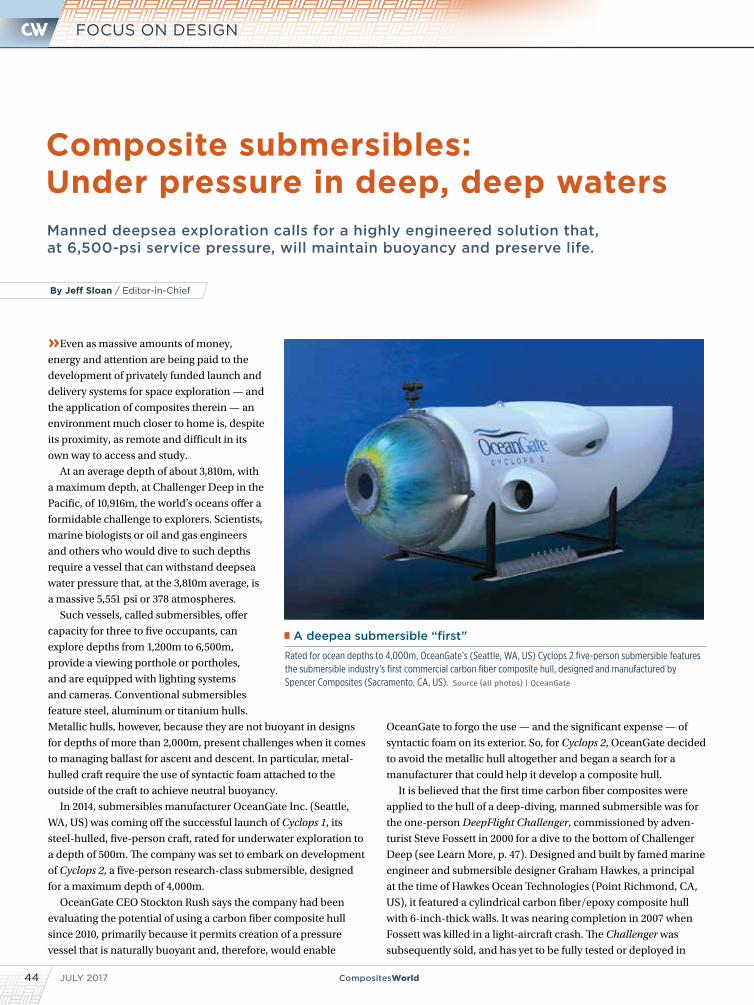
JULY 201744 CompositesWorld
FOCUS ON DESIGN
Composite submersibles: Under pressure in deep, deep watersManned deepsea exploration calls for a highly engineered solution that, at 6,500-psi service pressure, will maintain buoyancy and preserve life.
»Even as massive amounts of money,
energy and attention are being paid to the
development of privately funded launch and
delivery systems for space exploration — and
the application of composites therein — an
environment much closer to home is, despite
its proximity, as remote and difficult in its
own way to access and study.
At an average depth of about 3,810m, with
a maximum depth, at Challenger Deep in the
Pacific, of 10,916m, the world’s oceans offer a
formidable challenge to explorers. Scientists,
marine biologists or oil and gas engineers
and others who would dive to such depths
require a vessel that can withstand deepsea
water pressure that, at the 3,810m average, is
a massive 5,551 psi or 378 atmospheres.
Such vessels, called submersibles, offer
capacity for three to five occupants, can
explore depths from 1,200m to 6,500m,
provide a viewing porthole or portholes,
and are equipped with lighting systems
and cameras. Conventional submersibles
feature steel, aluminum or titanium hulls.
Metallic hulls, however, because they are not buoyant in designs
for depths of more than 2,000m, present challenges when it comes
to managing ballast for ascent and descent. In particular, metal-
hulled craft require the use of syntactic foam attached to the
outside of the craft to achieve neutral buoyancy.
In 2014, submersibles manufacturer OceanGate Inc. (Seattle,
WA, US) was coming off the successful launch of Cyclops 1, its
steel-hulled, five-person craft, rated for underwater exploration to
a depth of 500m. The company was set to embark on development
of Cyclops 2, a five-person research-class submersible, designed
for a maximum depth of 4,000m.
OceanGate CEO Stockton Rush says the company had been
evaluating the potential of using a carbon fiber composite hull
since 2010, primarily because it permits creation of a pressure
vessel that is naturally buoyant and, therefore, would enable
OceanGate to forgo the use — and the significant expense — of
syntactic foam on its exterior. So, for Cyclops 2, OceanGate decided
to avoid the metallic hull altogether and began a search for a
manufacturer that could help it develop a composite hull.
It is believed that the first time carbon fiber composites were
applied to the hull of a deep-diving, manned submersible was for
the one-person DeepFlight Challenger, commissioned by adven-
turist Steve Fossett in 2000 for a dive to the bottom of Challenger
Deep (see Learn More, p. 47). Designed and built by famed marine
engineer and submersible designer Graham Hawkes, a principal
at the time of Hawkes Ocean Technologies (Point Richmond, CA,
US), it featured a cylindrical carbon fiber/epoxy composite hull
with 6-inch-thick walls. It was nearing completion in 2007 when
Fossett was killed in a light-aircraft crash. The Challenger was
subsequently sold, and has yet to be fully tested or deployed in
By Jeff Sloan / Editor-in-Chief
A deepea submersible “first”
Rated for ocean depths to 4,000m, OceanGate’s (Seattle, WA, US) Cyclops 2 five-person submersible features the submersible industry’s first commercial carbon fiber composite hull, designed and manufactured by Spencer Composites (Sacramento, CA, US). Source (all photos) | OceanGate
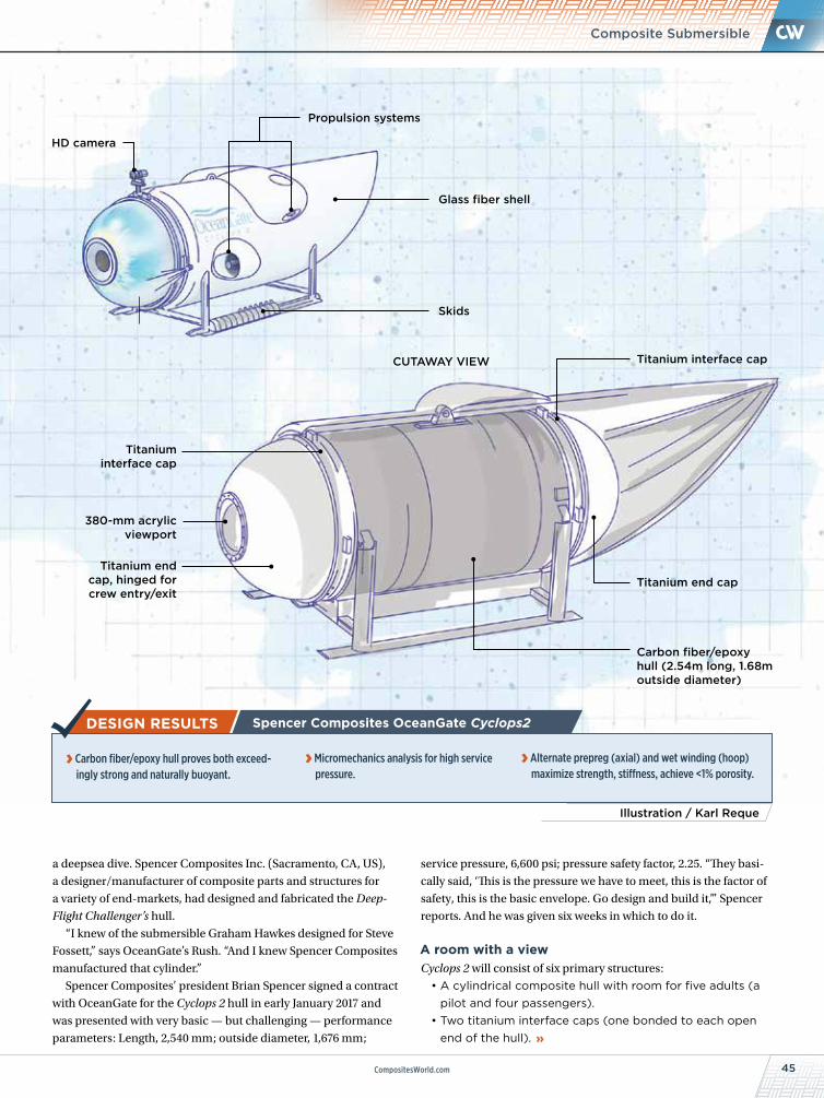
45CompositesWorld.com
Composite Submersible
a deepsea dive. Spencer Composites Inc. (Sacramento, CA, US),
a designer/manufacturer of composite parts and structures for
a variety of end-markets, had designed and fabricated the Deep-
Flight Challenger’s hull.
“I knew of the submersible Graham Hawkes designed for Steve
Fossett,” says OceanGate’s Rush. “And I knew Spencer Composites
manufactured that cylinder.”
Spencer Composites’ president Brian Spencer signed a contract
with OceanGate for the Cyclops 2 hull in early January 2017 and
was presented with very basic — but challenging — performance
parameters: Length, 2,540 mm; outside diameter, 1,676 mm;
Illustration / Karl Reque
Spencer Composites OceanGate Cyclops2
› Carbon fiber/epoxy hull proves both exceed-ingly strong and naturally buoyant.
› Micromechanics analysis for high service pressure.
› Alternate prepreg (axial) and wet winding (hoop) maximize strength, stiffness, achieve <1% porosity.
service pressure, 6,600 psi; pressure safety factor, 2.25. “They basi-
cally said, ‘This is the pressure we have to meet, this is the factor of
safety, this is the basic envelope. Go design and build it,’” Spencer
reports. And he was given six weeks in which to do it.
A room with a viewCyclops 2 will consist of six primary structures:
• A cylindrical composite hull with room for five adults (a pilot and four passengers).
• Two titanium interface caps (one bonded to each open end of the hull).
Titanium interface cap
380-mm acrylic viewport
Titanium end cap, hinged for crew entry/exit
CUTAWAY VIEW
Glass fiber shell
Skids
Propulsion systems
HD camera
Titanium interface cap
Titanium end cap
Carbon fiber/epoxy hull (2.54m long, 1.68m outside diameter)
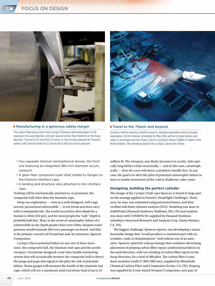
JULY 201746 CompositesWorld
FOCUS ON DESIGN
• Two separate titanium hemispherical domes, the front one featuring an integrated 380-mm-diameter acrylic viewport.
• A glass fiber composite outer shell, bolted to flanges on the titanium interface caps.
• A landing skid structure, also attached to the interface caps.
Nothing will be mechanically attached to, or penetrate, the
composite hull other than the titanium caps.
Deep-sea exploration — even in a well-designed, well-engi-
neered, pressurized submersible — is not trivial and does carry
with it substantial risk. The world record free-dive depth for a
human is 214m (312 psi), and for most people the “safe” depth is
probably half that. Thus, in the event of catastrophic failure of a
submersible at any depth greater than even 250m, deepsea water
pressure would instantly kill every passenger on board. And this
is the primary concern of OceanGate and, by extension, Spencer
Composites.
Cyclops 2 faces potential failure in any one of three struc-
tures: the composite hull, the titanium end caps and the acrylic
viewport. OceanGate designed a real-time health monitoring
system that will acoustically monitor the composite hull to detect
the pings and pops that signal to the pilot the risk of potential
failure. Strain gauges will measure the health of the titanium end
caps, which will see a maximum axial end dome load of up to 22
million lb. The viewport, says Rush, because it is acrylic, fails opti-
cally long before it fails structurally — and in this case, catastroph-
ically — thus the crew will detect a problem visually first. In any
case, the goal is to alert the pilot of potential catastrophic failure in
time to enable movement of the craft to shallower, safer water.
Designing, building the perfect cylinderThe design of the Cyclops 2 hull, says Spencer, is based in large part
on the strategy applied to Fossett’s DeepFlight Challenger. Thick-
ness, he says, was estimated using micromechanics, and then
verified with finite element analysis (FEA). Modeling was done in
SolidWorks (Dassault Systèmes, Waltham, MA, US) and analysis
was done with COSMOS/M, supplied by Dassault Systèmes
subsidiary Structural Research and Analysis Corp. (Santa Monica,
CA, US).
The biggest challenge, Spencer reports, was developing a manu-
facturable design that “would produce a consistent part with no
wrinkles, voids or delaminations.” And without use of an auto-
clave. Spencer opted for a layup strategy that combines alternating
placement of prepreg carbon fiber/epoxy unidirectional fabrics in
the axial direction, with wet winding of carbon fiber/epoxy in the
hoop direction, for a total of 480 plies. The carbon fiber is stan-
dard-modulus Grafil 37-800 (30K tow), supplied by Mitsubishi
Chemical Carbon Fiber and Composites (Irvine, CA, US). Prepreg
was supplied by Irvine-based Newport Composites, now part of
Manufacturing in a generous safety margin
The carbon fiber/epoxy hull of the Cyclops 2 features alternating layers of UD prepreg in the axial direction, and wet-wound carbon fiber filaments in the hoop direction. The hull is 127 mm thick (5 inches vs. the 6 inches planned for Fossett’s earlier craft) and has tested to 2.5 times the 6,500-psi service pressure.
Travel to the Titanic and beyond
Cyclops 2 will be used for scientific research, deepsea exploration and oil and gas exploration. Its first mission, scheduled for May 2018, will be to shoot photos and video of wreckage from the Titanic, which is located in about 3,688m of water in the North Atlantic. This rendering depicts the Cyclops 2 above the Titanic.
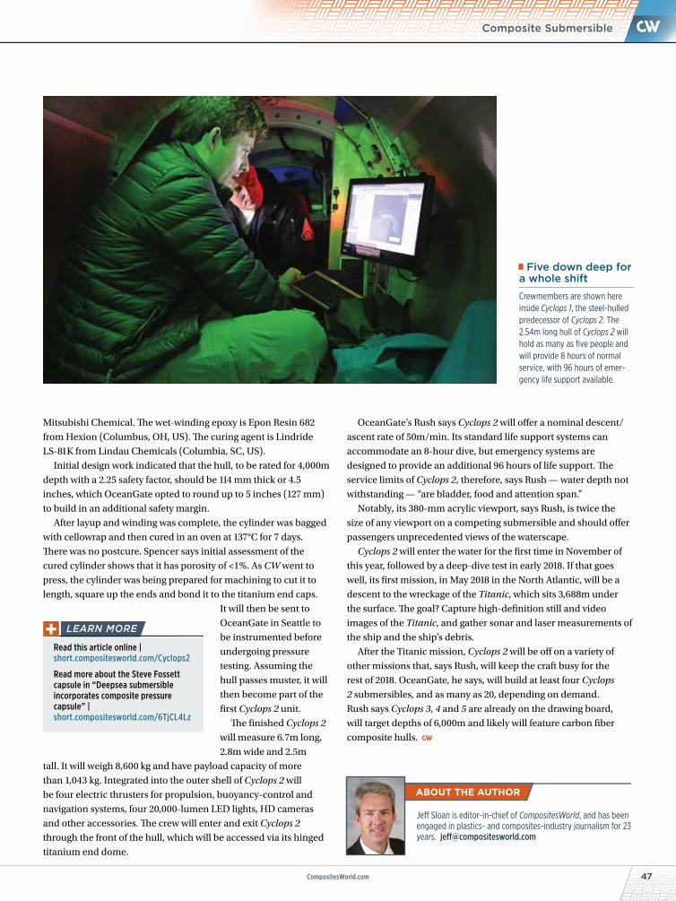
47CompositesWorld.com
Mitsubishi Chemical. The wet-winding epoxy is Epon Resin 682
from Hexion (Columbus, OH, US). The curing agent is Lindride
LS-81K from Lindau Chemicals (Columbia, SC, US).
Initial design work indicated that the hull, to be rated for 4,000m
depth with a 2.25 safety factor, should be 114 mm thick or 4.5
inches, which OceanGate opted to round up to 5 inches (127 mm)
to build in an additional safety margin.
After layup and winding was complete, the cylinder was bagged
with cellowrap and then cured in an oven at 137°C for 7 days.
There was no postcure. Spencer says initial assessment of the
cured cylinder shows that it has porosity of <1%. As CW went to
press, the cylinder was being prepared for machining to cut it to
length, square up the ends and bond it to the titanium end caps.
It will then be sent to
OceanGate in Seattle to
be instrumented before
undergoing pressure
testing. Assuming the
hull passes muster, it will
then become part of the
first Cyclops 2 unit.
The finished Cyclops 2
will measure 6.7m long,
2.8m wide and 2.5m
tall. It will weigh 8,600 kg and have payload capacity of more
than 1,043 kg. Integrated into the outer shell of Cyclops 2 will
be four electric thrusters for propulsion, buoyancy-control and
navigation systems, four 20,000-lumen LED lights, HD cameras
and other accessories. The crew will enter and exit Cyclops 2
through the front of the hull, which will be accessed via its hinged
titanium end dome.
Composite Submersible
OceanGate’s Rush says Cyclops 2 will offer a nominal descent/
ascent rate of 50m/min. Its standard life support systems can
accommodate an 8-hour dive, but emergency systems are
designed to provide an additional 96 hours of life support. The
service limits of Cyclops 2, therefore, says Rush — water depth not
withstanding — “are bladder, food and attention span.”
Notably, its 380-mm acrylic viewport, says Rush, is twice the
size of any viewport on a competing submersible and should offer
passengers unprecedented views of the waterscape.
Cyclops 2 will enter the water for the first time in November of
this year, followed by a deep-dive test in early 2018. If that goes
well, its first mission, in May 2018 in the North Atlantic, will be a
descent to the wreckage of the Titanic, which sits 3,688m under
the surface. The goal? Capture high-definition still and video
images of the Titanic, and gather sonar and laser measurements of
the ship and the ship’s debris.
After the Titanic mission, Cyclops 2 will be off on a variety of
other missions that, says Rush, will keep the craft busy for the
rest of 2018. OceanGate, he says, will build at least four Cyclops
2 submersibles, and as many as 20, depending on demand.
Rush says Cyclops 3, 4 and 5 are already on the drawing board,
will target depths of 6,000m and likely will feature carbon fiber
composite hulls.
Read this article online | short.compositesworld.com/Cyclops2
Read more about the Steve Fossett capsule in “Deepsea submersible incorporates composite pressure capsule” | short.compositesworld.com/6TjCL4Lz
Jeff Sloan is editor-in-chief of CompositesWorld, and has been engaged in plastics- and composites-industry journalism for 23 years. [email protected]
Five down deep for a whole shift
Crewmembers are shown here inside Cyclops 1, the steel-hulled predecessor of Cyclops 2. The 2.54m long hull of Cyclops 2 will hold as many as five people and will provide 8 hours of normal service, with 96 hours of emer-gency life support available.

www.theCAMX.org
September 11-14, 2017: Conference / September 12-14, 2017: Exhibits Orange County Convention Center / Orlando, Florida
Experience the Future of the Industry
UNSURP
ASSED INNOVATION
COMBINE
D STRENGTH
PLAN NOW TO ATTEND
CAMX 2017ORLANDO, FLORIDA
0417 CAMX.indd 1 3/20/17 10:34 AM

additivemanufacturing.media
Additive + Production
A PROPERTY OF:
Additive Manufacturing focuses on the industrial applications of 3D printing technology to make functional parts.
Get practical, applications-based info on the machines, materials and
methodologies being used to grow end-use tools and components.
PRINT | ONLINE | EMAIL | CONFERENCE
AM17_AM Brand_Full_.indd 1 3/14/17 11:04 AM
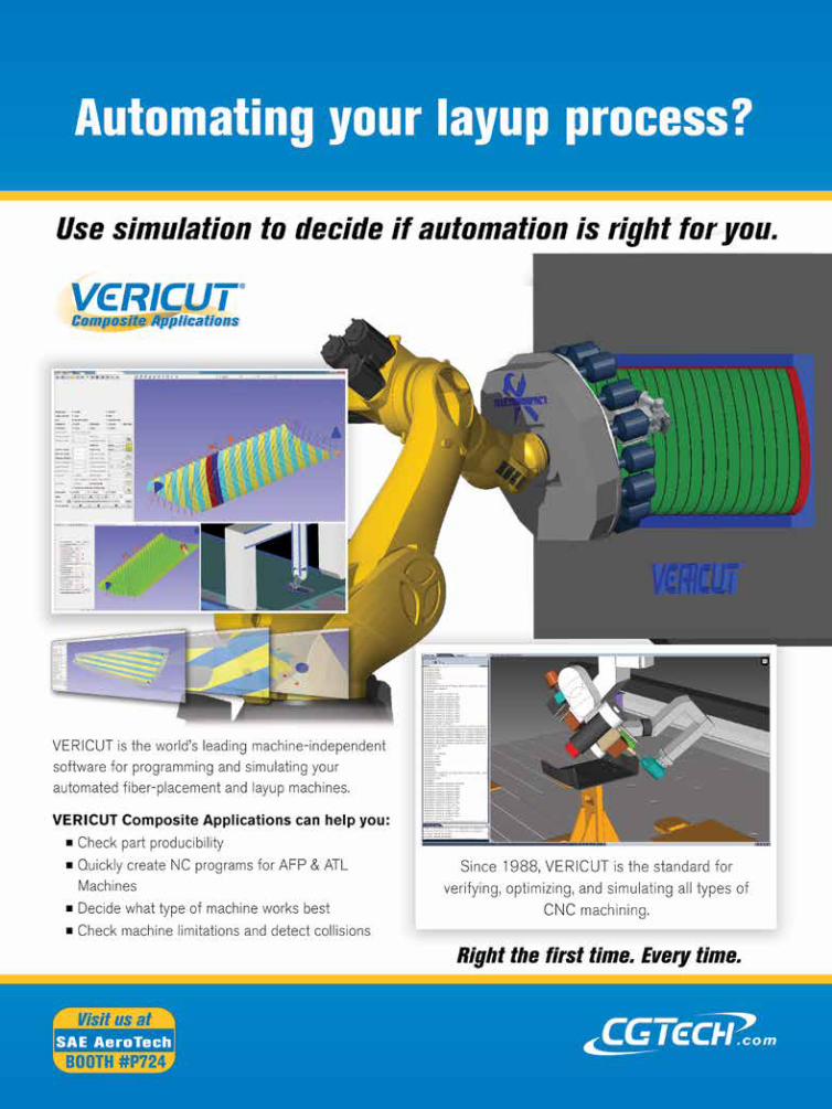
CW-Ad_CGTech-FullPage-2017-MTO.indd 1 6/9/2017 4:15:26 PM