Embed Size (px)
Citation preview
'1~' ''':-:;
.r= . -~-~-' r ~ ""', ;~ ," ~ ~ lES')f:)RPT -0205.00 SEPTEMBER 1974
LAW ENFORCEMENT STANDARDS PROGRAM
AUTOMATIC VEHICLE LOCATION
TECHNIQUES FOR LAW ENFORCE ENT USE
U.S. DEPARTMENT OF JUSTICE law Enforcement Assistance Administration
National Institute of law Enforcement and Criminal Justice
If you have issues viewing or accessing this file contact us at NCJRS.gov.
Library of Congress Cataloging in Publication Data
Fey, R L Automatic vehicle location techniques for law enforcement use.
At head of title: Law Enforcement Standards Program. "LESP-RPT-0205.00." Bibliography: p. L Police vehicles-Automatic location systems. 1. National Institute of Law Enforcement and Criminal
Justice. II. Title. Ill. Title: Law Enforcement Standards Program. HV7936.V38F48 1975 363.2'42 74-30357
,.
~~-- -~ -----
LAW ENFORCEMENT STANDARDS PROGRAM
AUTOMATIC VEHICLE LOCATION TECHNIQUES FOR
LAW E FORCEMENT USE
prepared for the National Institute of Law Enforc0ment and Criminal Ju:;1ice
law Enforcement Assistance Administration U.S. Department of Justice
by
R. L. Fey Electromagnetics Division
National Bureau of Standards
SEPTEMBER 1974
U.S. DEPARTMENT OF JUSTICE Law Enforcement Assistance Administration
National Institute of law Enforcement and Criminal Justice
For sal .. by the Superintendent of Documents, U.S. Government Printing Office Washington, D.C. 20402 • Price 75 cents
Stock Number 2700-002il2
LAW ENFORCEMENT ASSISTANCE ADMINISTRATION
Richard W. Ve Ide, Administrator
Charles R. Work, Deputy Administrator
NATIONAL INSTITUTE OF LAW ENFORCEMENT AND CRIMINAL JUSTICE
Gerald M. Caplan, Director
ACKNOWLEDGMENTS
This report was prepared by the Law Enforcement Standards Laboratory of the National Bureau of Standards under the direction of Marshall J. Treado, Program Manager for Communications Systems, and Jacob J. Diamond, ChiefofLESL.
ii
AUTOMATIC VEHICLE LOCATION TECHNIQUES FOR LAW ENFORCEMENT USE
Contents Page
Foreword................................................................................................ v Abstract................................................................................................ 1 1. Introduction .... , ... , .............................................................................. 1 2. Police Applications of Automatic Vehicle Location Systems................. 1 3. Automatic Vehicle Location Techniques...... ....................................... 2
3.1 Dead Reckoning Systems ................................................. ,............ 2 3.2 Proximity Systems... .................. .... ........... ............... ..................... 2 3.3 Radiolocation Systems.............................. .................................... 3
3.3.1 Radio Wave Propagation Effects............... ........................... 3 3.3.1.1 Very Low Frequency, VLF, 3-30 kHz.................................. 3 3.3.1.2 Low Frequency, LF, 30-300 kHz......................................... 3 3.3.1.3 Medium Frequency, MF, 300-3000 kHz................................ 3 3.3.1.4 High Frequency, HF, 3-30 mHz........................................... 3 3.3.1.5 Very High Frequency, VHF, 30-300 mHz............................. 4 3.3.1.6 Ultra High Frequency, UHF, 300-3000 mHz......................... 4 3.3.2 Technical Base for Location Systems... ................................... 4 3.3.3 Propagation in Urban Areas..... .............................................. 4 3.3.3.1 Multipath........................................................................... 4 3c3.3.2 Noise................................................................................ 5 3.3.4 Types of Radiolocation Systems...... ...... ................................. 6 3.3.4.1 Trilateration... .................... .......... ............. .......... ........... .... 6 3.3.4.2 Multilateration.................................................................... 10 3.3.4.3 Triangulation......... ......... ................................................... 10 3.3.4.4 Hybrid Systems.................................................................. 10
4. Precision and Accuracy of Vehicle Location Systems.............................. 11 4.1 Errors.......................................................................................... 11
4.1.1 Dead Reckoning.................................................................. 11 4.1.2 Proximity.......................................... ...... ........................... 11 4.1.3 Radiolocation........................................................................ 11
4.2 Accuracy.............................. ...................................................... 12 4.2.1 A VL Measurement Accuracy................................................ 13 4.2.2 Techniques for Improving Accuracy....................................... 13
5. Location Data Reporting Systems......................................................... 14 5.1 Narrowband Communication........................................................... 14 5.2 Wideband Communication.............................................................. 15 5.3 Location Update Rates...... ............................................................ 15
5.3.1 Dead Reckoning Rates......................................................... 16 5.3.2 Proximity Rates.................................................................... 16 ~.3.3 Radiolocation Rates............................................................... 16
6. Information Displays... ........................................................................ 16
iii
CONTENT' Page
7. Commercial A VL Systems.................................................................. 17 7.1 Dead Reckoning........................................................................... 17 7.2 Proximity............ ......... ............................................................... 17 7.3 Radiolocation Systems.......................................................... ........ 17
7.3.1 Phase Trilateration............................................................... 17 7.3.2 Pulse Trilateration................................................................. 18 7.3.3 Navigation Systems... ............................................................ 18 7.3.3.1 Loran C... ... ... ................................................................... 18 7.3.3.2 Decca ........................................ '" ......... ............... ............ 18 7.3.3.3 Omega......... ..................................................................... 18 7.3.3.4 Differential Navigation Systems ...... '" ................................... 18
8. Radio Spectrum Utilization................................................ .................. 18 9. System Costs........................... ......................................................... 19 10. Comparisons of AVL System Techniques...... ...... ...... ......... ................ 19 Annotated Bibliography...... ... .................................................................... 22
iv
FOREWORD
Following a Congressional mandate I to develop new and improved techniques, systems, and equipment to strengthen law enforcement and criminal justice, the National Institute of Law Enforcement and Criminal Justice (NILECJ) has established the Law Enforcement Standards Laboratory (LESL) at the National Bureau of Standards. LESL's function is to conduct research that win assist law enforcement and criminal justice agencies in the selection and procurement of quality equipment.
In response to priorities established by NILECJ, LESL is (1) subjecting existing equipment to laboratory testing and evaluation and (2) conducting research leading to the development of several series of documents, including national voluntary equipment standards, user guidelines, state-of-the-art surveys and other reports.
This document, LESP-RPT-0205.00, Automatic Vehicle Location Techniques for Law Enforcement Use, is a law enforcement equipment report prepared by LESL and issued by NILECJ. Additional reports as well as other documents will be issued under the LESL program nn the areas of protective equipment, communications equipment, security systems, weapons, emergency equipment, investigative aids, vehicles and clothing.
Technical comments and suggestions concerning the subject matter of this report are invited from all interested parties. Commentt' should be addressed to the Program Manager for Standards, National Institute of Law Enforcement and Criminal Justice, Law Enforcement Assistance Administration, U.S. Department of Justice, Washington, D.C. 20531.
LESTER D. SHUBIN, Manager, Standards Program National Institute of Law
Enforcement and Criminal Justice
I Section 402(b) of the Omnibus Crime Control and Safe Streets Act of '%8, as amended.
v
LESP-RPT-020S.00
AUTOMATIC VEHICLE LOCATION TECHNIQUES FOR LAW ENFORCEMENT USE
ABSTRACT
Automatic vehicle location systems employing communications techniques are presently under development by several companies. This report discusses such systems with respect to law enforcement applications. It presents the principles upon which the various automatic location techniques are based, summarizes their important characteristics, and compares them as candidates for law enforcement use. This report discusses techniques, available system performance, and the related aspect of frequency spectrum requirements for these systems. It also mentions areas where !TIore operational information is needed before systems for law enforcement operations can be clearly defined.
1. INTRODUCTION
In order to dispatch patrol cars efficiently, some knowledge of car location is necessary. The earliest car location method used was to divide the city into sections, known as beats, and to assign a patrol car to each beat. The only assumption made was that the car would be found somewhere within the beat. Present dispatching methods have evolved from this beginning. Since it is usually advantageous to dispatch the car nearest to a scene.; identifying it is important. Frequently a car from another beat is the nearest one available for dispatching to a given location. Verbal location by radio is time consuming and is poor management of the radio spectrum. An Automatic Vehicle Location (A VL) system could save time and improve spectrum usage. By keeping the dispatcher continuously informed of patrol fleet deployment, an A VL system could also improve coordination of police activities and make possible the development of improved dispatching strategies. strategies.
2. POLICE APPLICATIONS OF AUTOMATIC VEHICLE LOCATION SYSTEMS
A variety of car location techniques have been suggested and some have undergone considerable development, although none have yet undergone large scale te .. ting. Activity in this field has been stimulated considerably by the report of the President's Commission on Law Enforcement and Administration of Justice, February 1967. The Task Force Report, "Science and Technology," lists four possible types of vehicle location techniques:
a. A system of patrol car emitters and call box sensors. b. A modified radar transponder system. c. A medium-frequency radio direction-finder system. d. A car-borne position computation and reporting system.
Subsequent developments in the field have made it appropriate to alter this classification somewhat. The radar technique as described has not been fully developed. Parts of the radar transponder scheme, however, have been incorporated into some of the radio location systems. The radio direction finder technique may be considered a subclass of a rather extensive class of radiolocation techniques which has been developed. The first and last techniques listed above have been pursued and are known respectively as proximity and dead reckoning systems.
In this report, A VL techniques are classified into three categories: 1. Dead Reckoning Systems (as in item d above). The vehicle carries instruments
to measure direction and distance traveled. From these data a computer determines the estimated vehicle position.
2. Proximity Systems (as in item a above). These systems identify a vehicle when it passes near certain fixed locations. These locations may be equipped with either sensors or emitters for signaling the vehicle, usually by radio.
3. Radiolocation Systems (as in item c above). These systems use the unique characteristics of radio fields themselves to establish vehicle location, as contrasted to use of radio to report vehicle location. They must employ more than one fixed radio terminal in order to operate. Trilateration, triangulation and navigation systems are included in this category.
For law enforcement use, an A VL system must provide location information to a central dispatcher, usually through radio links. Location information must be presented to the dispatcher in a form useful to him. Generally this would be a map display of the city on which is indicated the vehicle's identification and location as it moves throughout the service area. A television type display is usually the primary form of presentation. Where computer-aided dispatching is included, interfacing with that system is necessary. For emergency situations when a patrol officer requires assistance, A VL systems can be provided with an alarm capability. This enables the officer to signal for help at his intJi;;at.ed location.
A vari~ty of A VL systems are now being offered. They differ in the precision and accuracy achieved, radio spectrum needed, rate of update of location information, ability to accommodate new vehicles in the system, size of vehicle fleet which may be accommodated, area which may be covered, and tolerance to problems caused by various urban circumstances. Since A VL systems are not yet available in commercial production quantities, and system specifications depend on individual installation circumstances, definite cost figures are lacking. However, estimates can be made and trends can be identified.
3. AUTOMATIC VEHICLE LOCATION TECHNIQUES
3.1 Dead Reckoning Systems These systems obtain necessary location data using instrumentation carried entirely
within the vehicle and need no interaction with externally placed system elements. This instrumentation usually consists of an odometer to measure the distance traveled and a compass to measure the direction of travel.
As the vehicle travels, the data produced by these instruments are processed to derive the vehicle's position with respect to its starting point. Data processing may be done within the vehicle, or the data may be relayed to a computer at the central dispatch location for processing. Since the system operates without referring to external coordinates, the vehicle's initial position on the map must be inserted in order for its computed path to correspond to its position on the map. Errors in the odometer and errors in the compass heading cause cumulative errors in the vehicle's calculated location which eventually cause the vehicle to become "lost." Such errors are unavoidable in any system which operates over a period of time without an external reference. An analogous case is a free running clock. It must be reset sooner or later if its error in time is to remain within bounds. Therefore a dead reckoning A VL system should include a means for correcting errors before they become too large. One demonstrated method makes use of the fact that a vehicle is confined to a drivable surface in a city. Ordinarily this would be the network of city streets. A street map of the city is stored in computer memory. The indicated vehicle position is compared with the map, and path discrepancies are corrected to cause the vehicle to appear on the nearest appropriate street. This technique is known as map-matching.
3.2 Proximity Systems Proximity systems require the vehicle to pass near one of a set of specially equipped
"sign posts" distributed throughout the city in order for its location to be identified.
2
Ordinarily a low-powered microwave transmitter is mounted on the sign post, and an encoded location address is transmitted continuously. As the vehicle passes nearby, it receives the address signal and decodes it. This location information is stored in the vehicle and sent to the central dispatch location by radio when requested.
An inverted proximity system may also be used. In this form the vehicle sends its identity code continuously by means of a low power transmitter. When the vehicle passes near a sign post equipped with a receiver, the identifying signal is detected and relayed to the central dispatch location, usually by telephone lines. Police call box circuits or fire alarm circuits appear to be particularly suitable for this use since they are readily available in a number of locations throughout most cities.
3.3 Radiolocation Systems 3.3.1 Radio Wave Propagation Effects
Most A VL methods make use of radio propagation both in the location process and for sending location information to the dispatcher. A summary of radio propagation effects follows.
Radio waves usually travel from the transmitting antenna to the receiving antenna by several different routes. In free space they propagate directly from the antenna, decreasing in amplitude with distance. This is known as free space or space wave propagation. If the antennas are both near the ground, this provides a means for another mode of propagation: a wave which travels along the ground and is called a ground wave. The ground wave attenuation is lowest for the lowest frequencies. A third type of wave is possible because the earth is surrounded by free electrons in a region above the atmosphere known as the ionosphere. The ionosphere electrons tend to be concentrated in several layers. Radio waves are reflected from these layers under certain conditions and are returned to the earth. Such waves are called ionospheric waves or sky waves. One or more of the three types of wave is involved in any radio communication system. However, propagation effects depend strongly on the frequency used. For convenience, the radio frequency spectrum has been divided into bands which have been given descriptive names. The most important characteristics of these bands follow. 3.3.1.1 Very Low Frequency, VU:, 3-30 kHz
This is the lowest frequency band of interest in automatic vehicle location. It has the advantage of stable and reliable propagation over very long distances, up to worldwide. Both ground waves and ionospheric waves are present for distances up to several thousand miles; after that, only ionospheric waves are important. The ionospheric waves are those reflected from the lowest, most stable layer of the ionosphere. This band can be used for communication, but only at a very low information rate. The long range navigation system called Omega operates in this band. It is useful for ocean navigation, but reducing its uncertainty to less than a mile is difficult. 3.3.1.2 Low Frequency, LF, 30-300 kHz
This band, similar to VLF, is also characterized by stable long range propagation, but much less than worldwide. Higher communication rates are possible. The Loran C navigation system (see bibliography) operates in this band with considerably better accuracy than Omega but over a smaller area 3.3.1.3 Medium Frequency, MF, 300-3000 kHz:
The ground wave coverage in this band continues to decrease until it is only a few tens of miles at the high end of the band. Ionospheric waves reflected from the upper layers of the ionosphere become important for long distance transmissions. However, these layers are generally unstable and change greatly from day to night, over the yearly seasons, and with sun spot-cycles. The AM broadcast band occupies the lower end of this band. 3.3.1.4 High Frequency, HF, 3-30 MHz
Very long distance transmissions are sometimes possible in this band through ionospheric reflections, subject to the same kinds of uncertainties as in the MF band.
3 566-723 0 - 75 - 2
3.3.1.5 Very High Frequency, VHF, 30-300 MHz As the frequency increases, free~space type waves which travel over line-of-sight
paths become predominant. At the lower end of this band ionospheric reflections sorne~ times account for ·;ery long distance transmission. In the rest of this band the free space waves are bent by the atmosphere, sometimes resulting in very long distance transmis~ sions. At the higher end of the band the free space waves are sometimes trapped by the multilayered ionosphere and reflected, or are reflected by the troposphere, again resulting in very long distance transmissions. These bending phenomena are affected by vary~ ing weather conditions such as atmospheric temperature and water vapor content. This dependence increases as the frequency increases. In urban areas, wave reflections occur from buildings and other objects. Signals arriving by means of these reflections inter~ fere with the direct line-of-sight waves, sometimes causing reinforcement and sometimes nearly complete cancellation due to destructive interference. These effects are known as multipath fading. . 3.3.1.6 Ultra High Frequency, UHF, 300-3000 MHz
The direct waves are most important here. Multipath phenomena also remain important in urban areas. If a receiving antenna is moving, muitipath fading occurs more often at the higher frequencies. 3.3.2 Technical Base for Location Systems
Radio signals have two important properties which make them useful in position location or navigation systems. First, the velocity of propagation of radio waves is essential1y constant at the speed of Hght. This aHows a measurement of the time it takes for a radio wave to travel from transmitter to receiver to be converted to a measurement of distance. Methods which employ this principle are known as trilateration methods (described in paragraph 3.3.4.1). The term is also used to describe vehicle location systems which employ this principle. Second, radio waves travel essentially in straight lines from a transmitting antenna. This allows a measurement of the wave direction to be made at the receiver. When plotted on a map, this becomes the direction to the transmitter from the receiver. Methods which employ these measurements are known as triangulation methods (described in paragraph 3.3.4.3). As before, the same term is used to describe vehicle location systems which employ this principle. 3.3.3 Propagation in Urban Areas
The presence of buildings and other man-made structures in cities significantly affects propagation characteristics. Furthermore, man-made electrical noise and interference are concentrated in the cities. These effects influence the operation of radiolocation A VL devices in urban areas, generally causing degradation of accuracy and reliability. The effects apply in two different ways: first through reflection of radio waves from man-made structures and second by attenuation of the waves in passing through such structures. These effects are a function of the length of the propagated wave relative to the dimensions of the manmade structures involved. 3.3.3.1 Multipath
In the VLF and LF bands, the wavelengths used vary from about 20 miles to a mile or so. Only long metallic structures such as power lines, metallic bridges, and so forth have dimensions comparable to an appreciable fraction of a wavelength and can affect propagation appreciably. When waves are reflected or reradiated, the phase of the signal is altered. In addition, if a receiving antenna is located near or under large metallic structures, the VLF or LF signal received may be attenuated significantly.
In the VHF and UHF bands, where the wavelengths are a few meters or less, wave reflections are more common. These reflections occur mostly from buildings but also from the ground or pavement. The result at a receiving antenna is the reception of the same signal over numerous paths. The direct path transmission, being the shortest distance, occurs with the least time delay; the others occur with increased delays up to 10 microseconds or more, corresponding to reflections from several miles away. For radio recep-
4
tion in urban environments this causes a problem. The additional multipath signals alter the phase of the received signal and also interfere with the direct signal, causing it to fade. Severe fading of the signal often occurs as the receiving antenna is moved through a distance comparable to a wavelength. On the average, the multipath effect causes a VHF or UHF radio wave to be attenuated more than if it were propagating in free space. This attenuatior. increases as frequency increases. 3.3.3.2 Noise
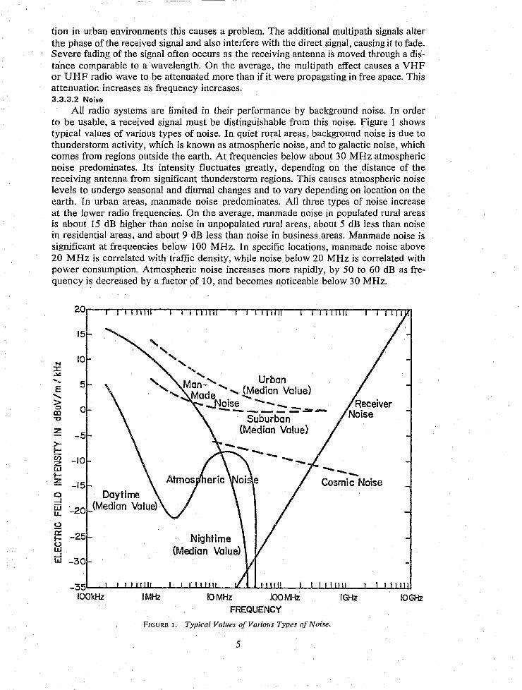
All radio systems are limited in their performance by background noise. In order to be usable, a received signal must be distinguishable from this noise. Figure 1 shows typical values of various types of noise. In quiet rural areas, background noise is due to thunderstorm activity, which is known as atmospheric noise, and to galactic noise, which comes from regions outside the earth. At frequencies below about 30 MHz atmospheric noise predominates. Its intensity fluctuates greatly, depending on the distance of the receiving antenna from significant thunderstorm regions. This causes atmospheric noise levels to undergo seasonal and diurnal changes and to vary depending on location on the earth. In urban areas, manmade noise predominates. All three types of noise increase at the lower radio frequencies. On the average, manmade noise in populated rural areas is about 15 dB higher than noise in unpopulated rural areas, about 5 dB less than noise in residential areas, and about 9 dB less than noise in business.areas. Manmade noise is significant at frequencies below 100 MHz. In specific locations, manmade noise above 20 MHz is correlated with traffic density, while noise below 20 MHz is correlated with power consumption. Atmospheric noise increases more rapidly, by 50 to 60 dB as frequency is decreased by a factor of 10, and becomes noticeable below 30 MHz.
N :I: ~
" E
" > .::::I co "t:I
z >r-
15
10
5
o
-5
en z -10 w I-~ -15
, " " "
'" Ma~ """ "" Urban '...... Made ....... ~edian Value)
....:.riolse - - __ --.. _______ ..:::JIiI ......
Suburban (Median Value)
---Cosmic Noise o Daytime ~ (Median Value) LL -20
5:2 ~ -25 fd ...J W -30
-3~~~~~~~-~~~~~~~~~~~~~~~~~~
100kHz I MHz [0 MHz 100 MHz IGHz IOGHz FREQUENCY
FIGURE 1. Typical Values of Various Types of Noise.
5
3.3.4 Types of Radiolocation Systems 3.3.4.1 Trilateration
Of the various approaches taken by manufacturers in attempting to develop A VL systems, trilateration has been the most common. Some variation in detail is possible but all such systems require radio transmissions between the vehicle and three fixed locations. The installations at the three fixed locations may consist of radio transmitters, in which case the vehicle receives transmissions from ea~h of the three locations; or the vehicle may transmit and the three fixed locations receive. In the case of VLF or LF systems, the vehicle must receive, because at such long wavelengths a suitable transmitting antenna would be impractical for a vehicle. S~veral VLF and LF systems are already in operation for ship and aircraft navigation and are known as Navigation Systems. At VHF and UHF frequencies either scheme may be used, but most commercial systems use the vehicle to transmit. This eases the data handling and equipment problem since, if the vehicle receives, the received information must be retransmitted to the dispatch location, with or without processing on boarG the vehicle; while if the vehicle transmits, receivers are only necessary at the three fixed site;;, and all data pru..:essing may be done at a central location. In principle, the frequency bands between LF and VHF could be used for vehicle location purposes, but the present crowding of these bands and the possibility of interference over very long distance paths makes them unattractive for such use.
Whether a vehicle transmits or receives, trilateration vehicle location systems employ the same geometry and are based on the fact that radio signals travel with a constant velocity. Thus a knowledge of the time taken for a radio signal to propagate over a given path allows the length of that path to be calculated. This becomes the basis for the most straightforward, although rather expensive, vehicle location system, often called the circular or range-range system. 3.3.4.1.1 Range-Range System
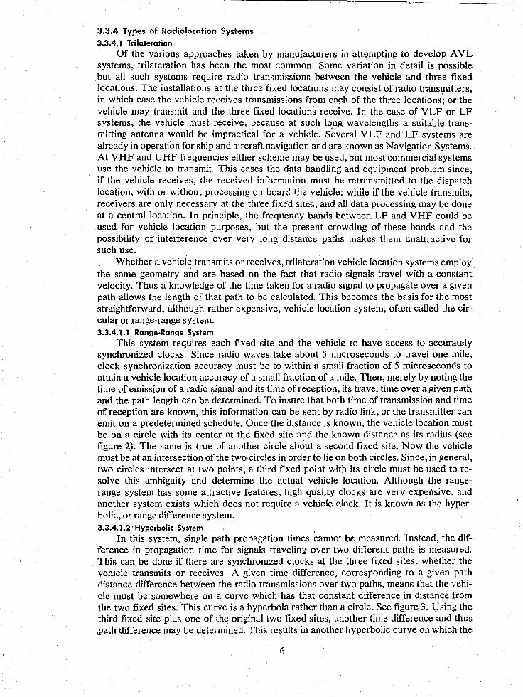
This system requires each fixed site and the vehicle to have access to accurately synchronized clocks. Since radio waves take about 5 microseconds to travel one mile, clock synchronization accuracy must be to within a small fraction of 5 microseconds to attain a vehicle location accuracy of a small fraction of a mile. Then, merely by noting the time of emission of a radio signal and its time of reception, its travel time over a given path and the path length can be determined. To insure that both time of transmission and time of reception are known, this information can be sent by radio link, or the transmitter can emit on a predetermined schedule. Once the distance is known, the vehicle location must be on a circle with its center at the fixed site and the known distance as its radius (see figure 2). The same is true of another circle about a second fixed site. Now the vehicle must be at an intersection of the two circles in order to lie on both circles. Since, in general, two circles intersect at two points, a third fixed point with its circle must be used to resolve this ambiguity and determine the actual vehicle location. Although the rangerange system has some attractive features, high quality clocks are very expensive, and another system exists which does not require a vehicle clock. It is known as the hyperbolic, or range difference system. 3.3.4.1.2 Hyperbolic System
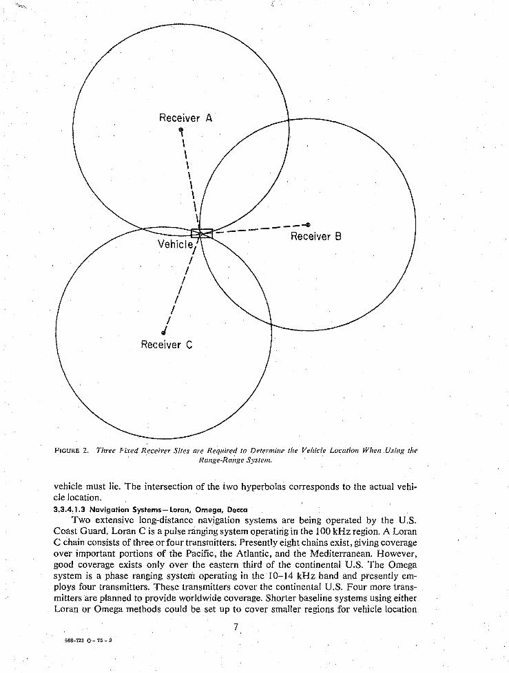
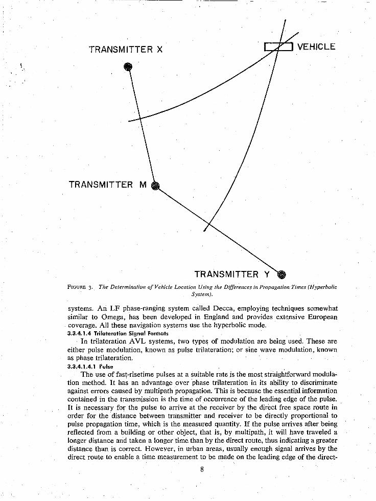
In this system, single path propagation times cannot be measured. Instead, the difference in propagation time for signals traveling over two different paths is measured. This can be done if there are synchronized clocks at the three fixed sites, whether the vehicle transmits or receives. A given time difference, corresponding to a given path distance difference between the radio transmissions over two paths, means that the vehicle must be somewhere on a curve which has that constant difference in distance from the two fixed sites. This curve is a hyperbola rather than a circle. See figure 3. U sing the third fixed site plus one of the original two fixed sites, another time difference and thus .path difference may be determined. This results in another hyperbolic curve on which the
6
Receiver A , \ \ \ \ \ \ \ \ ----4
---t::2::s;J - -- - - Receiver B Vehicle,
I , I ,
/ , I
J Receiver C
FIGURE 2. Three Fixed Receiver Sites are Required to Determine the Vehicle Location Wilen Using the Range-Range System.
vehicle must lie. The intersection of the two hyperbolas corresponds to the actual vehicle location. 3.3.4.1.3 Navigation Systems- Loran, Omega, Decca
Two extensive long-distance navigation systems are being operated by the U.S. Coast Guard. Loran C is a pulse ranging system operating in the 100 kHz region. A Loran C chain consists of three orfour transmitters. Presently eight chains exist, giving coverage over important portions of the Pacific, the Atlantic, and the Mediterranean. However, good coverage exists only over the eastern third of the continental U.S. The Omega system is a phase ranging system operating in the 10-14 kHz band and presently employs four transmitters. These transmitters cover the continental U.S. Four more transmitters are planned to provide worldwide coverage. Shorter baseline systems using either Loran or Omega methods could be set up to cover smaller regions for vehicle location
7 566-723 0 - 75 - 3
TRANSM ITTE R X
TRANSMITTER Y FIGURE 3. The Determination of Vehicle Location Using the Differences ill Propagation Times (Hyperbolic
System).
systems. An LF phase-ranging system called Decca, employing techniques somewhat similar to Omega, has been developed in England and provides extensive European coverage. All these navigation systems use the hyperbolic mode. 3.3.4.1.4 Trilateration Signal Formats
In trilateration AVL systems, two types of modulation are being used. These are either pulse modulation, known as pulse trilateration; or sine wave modulation, known as phase trilateration. 3.3.4.1.4.1 Pulse
The use of fast-risetime pulses at a suitable rate is the most straightforward modulation method. It has an advantage over phase trilateration in its ability to discriminate against errors caused by multipath propagation. This is because the essential information contained in the transmission is the time of occurrence of the leading edge of the pulse. It is necessary for the pulse to arrive at the receiver by the direct free space route in order for the distance between transmitter and receiver to be directly proportional to pulse propagation time, which is the measured quantity. If the pulse arrives after being reflected from a building or other object, that is, by multipath, it will have traveled a longer distance and taken a longer time than by the direct route, thus indicating a greater distance than is correct. However, in urban areas, usually enough signal arrives by the direct route to enable a time measurement to be made on the leading edge of the direct-
8
path pUlse. Then multi path only has the effect of lengthening the pulse as received or, if the indirect path is long enough, to cause one or more pulses to appear following the initial pulse. These spurious effects can be largely ignored and errors greatly reduced by the use of proper measuring circuitry. The chief errors occur when the direct-path signal amplitude is so low that the earliest multipath pulse is the one on which the time measurement is made. This always causes an over-estimation of path propagation time. The chief disadvantage of this method is the wide bandwidth, approximately 10 MHz, needed to transmit a pulse with suitably short rise time, approximately 0.1 microsecond. 3.3.4.1.4.2 Phase
In contrast to the pulse method, phase trilateration uses sine wave modulation and requires a relatively low bandwidth. However, instead of the time of occurrence of a fast rise pulse, the essential information is now contained in the time of occurrence of zero-crossings of a low frequency sine wave. This information is obtained at the receiver by measuring the phase of the sine wave. The effect of multipath is to add reflected sine waves to the direct-path sine wave at the receiver. The phase of the resultant is now the only information available, and no method exists to separate the direct wave from the reflected waves. The errors are considerably larger on the average than with pulse trilateration, and can cause underestimation of path propagation times as well as overestimation. 3.3.4.1.5 Data Exchange
The three fixed trilateration system sites generally must be provided with means for data exchange among them. In addition, if transmitters are located at these sites, it is preferable, but not essential, that they operate from synchronized clocks. Details vary according to the system type, but generally two types of communication channels may be employed. One i$ a data channel; the other is a clock channel which must have a time delay stability suitable to its use for clock synchronization or comparison. 3.3.4.1.6 Fixed Site Used for Transmitting
If the three fixed sites employ transmitters, system operation is simplified if the transmitter clocks are synchronized. This may be accomplished in several ways. A separate communication channel can be used to send synchronizing pulses from one transmitter site to another. Such channels must have sufficient bandwidth and known signal delay characteristics. Alternatively, each broadcast itself can be monitored at the other transmitter locations, allowing time adjustments to be made to keep all clocks in synchronism. This procedure is simplified if one station clock is designated as the master and the others are adjusted to agree with it. The system can also operate if the transmitter clocks are unsynchronized. In that case a monitor is necessary to determine the disagreement, or differences, among the clocks at the various transmitters. These differences must then be incorporated into each computation of vehicle location, and this information must be supplied to the facility where these computations are made. A data communication channel, in contrast to a stable time synchronization channel, is all that is needed for this purpose. 3.3.4.1.6.1 Loran and Omega
The only radio location systems presently under discussion employing fixed sites used for transmitting are the VLF and LF Omega and Loran systems. The Omega transmitters are kept in synchronism by monitoring all the broadcasts to determine what individual station adjustments are necessary. In the case of Loran, each chain consists of a "master" transmitter and two or three "slaves." Their broadcasts are monitored, and the slaves are adjusted individually to agree with the master. 3.3.4.1.6.2 Differential Loran and Omega
For improving Loran or Omega system accuracy over limited areas, monitoring stations may be employed in a different mode. Instead of being used to determine transmitter adjustments, they can be used to measure local variations in received signals due to propagation changes. This information can be disseminated and used to refine the
9
position estimation made by a navigation receiver or a vehicle location system. Systems employing this technique are known as differential Omega or differential Loran and are still under development. 3.3.4.1.7 Fixed Site Used for Receiving
In this case two modes of operation exist. The field sites may contain clocks which are synchronized through suitable clock channels. The times of reception of the vehicle signal may then be determined at each site. This information is sent by data channel to the facility where the vehicle location computation is made. Alternatively, the transmissions from the vehicle may be received at each site and relayed, or transmitted, by clock channel to the vehicle location computation facility. 3.3.4.2 Multilateration
The minimum number of fixed sites required of radio location systems which operate by measuring signal propagation time is three. Additional stations may be used both to provide a greater area of coverage and to improve system accuracy through increased data acquisition. Such systems are frequently called multilateration systems. 3.3.4.3 Triangulation
A VL systems based on measurement of the direction of arrival of radio signals are known as triangulation systems. A signal may be transmitted from a vehicle and received at a fixed site where its direction of arrival is determined. This determines a position line on which the vehicle must be located. A similar measurement at a second fixed site determines another position line. The vehicle is located where the two lines intersect. This procedure is not very accurate when the vehicle is located on a line between the two fixed sites, so a third fixed site is necessary. The same technique may be used if the vehicle receives transmissions from the fixed sites. The technique for determining the the directioL of signal arrival employs directional antenna systems similar to those that have been extensively used in radio direction-finding systems. Multipath reflections from objects close to the transmitter do not greatly change the direction of arrival of the signal and therefore do not cause significant errors. However, the opposite is true of reflections close to the receiver. Therefore, it is advantageous to place the transmitter in the vehicle and locate the receiving antenna away from nearby reflection points. 3.3.4.4 Hybrid Systems
For some applications it may be advantageous to combine elements of two systems to improve overall system performance or to overcome specific problems.
Because the dead reckoning system depends on having a correct initial reference point, a temporary system failure produces more drastic restart problems than it would with the other systems. One suggestion to reduce this problem might oe to provide a limited number of proximity sign posts which would then provide recalibration points at intervals throughout the service area.
Alternatively, a proximity system could be provided with a simple odometer dead reckoning arrangement to interpolate position between sign posts in order to improve system accuracy. If this is done on a fixed route vehicle, such as a bus, it could provide accurate position information continuously. Its utility for random route police patrol is doubtful.
Another method which has received attention is to add a signal amplitude measuring capability to a proximity system. This would permit making an estimate of a vehicle's distance from the sign post based on received signal amplitude. The average attenuation rate of signal levels vs. distance in an urban environment is known. Although high accuracy is not possible, the knowledge that the vehicle is nearer or farther than a certain range would be of considerable value, and perhaps not too difficult to obtain.
Another way of combining systems could be to use one type in a certain area of a city and another type in a different area. For instance, the downtown high-rise area of a city is a very difficult multi path and interference environment for radio trilateration systems. It is also the area where patrol beats are smallest. To provide the same ad van-
10
tage, an A VL system must have higher accuracy in a small beat than in alarge beat. Thus, where the highest accuracy is needed, trilateration systems have the most difficulty providing it. On the other hand, performance of proximity systems is unaffected by highrise environments. They can be placed as close together as needed to obtain accuracy, and lowering transmitter power to avoid interference. Since the downtown high-rise area is a small part of a city, the number of sign posts required may not increase the cost excessively. A trilateration system could then provide coverage for the rest of the city. Some elements of the two systems could be shared, such as their communication facilities.
4. PRECIS~ON AND ACCURACY OF VEHICLE LOCATION SYSTEMS
Accuracy is a measure of how correctly a vehicle's location is indicated by the vehicle location system. In order to evaluate system performance and compare different systems, a quantitative specification of accuracy is necessary. To be meaningful, this specification must be based on a realistic model of system behavior with respect to errors. Such models will differ depending on which of the three types of systems is being considered: dead reckoning, proximity, or radiolocation. The main characteristics of error performance of these systems are discussed in the following paragraphs.
4.1 Errors 4.1.1 Dead Reckoning
The dead reckoning system which has been demonstrated depends on the use of map matching to correct errors; otherwise, errors would increase indefinitely as the system operated. Generally, as the system operates, errors graduaIly accumulate until they exceed a certain predetermined amount. Then they are corrected in one step, indicating that the vehicle is back on a street on the map. Lateral errors, where the vehicle path appears to gradually depart from a street on an angle, are caused by compass heading errors and are easily recognized. Distance errors, where the vehicle appears to go faster or slower than its actual speed, are due to odometer errors and cc:\nnot be recognized as long as the vehicle travels in a straight line. Their only manife~'tation would !Je a velocity error. However, the map matching system does detect these errors if the vehicle appears to make a turn where no cross street is indicated on the ',hap. In such a case, if the distance error is less than half a block, the error would be properly corrected by the system. If the error is greater than half a block, the system would change the indicated vehicle position to be on the nearest, but incorrect, street. By employing more sophisticated computer software, even these errors can be later corrected when further path discrepancies are noted. The most serious problem would occur if the computer failed and lost all memory of the vehicle position. This problem could be eventuaIly corrected if the city map remained in memory and if vehicle position data could be reinserted into memory. 4.1.2 Proximity
In this system the city can be considered to be divided into a set of contiguous cells with a sign post in each. In the ideal system, the cell boundaries would be located such that as a vehicle crossed one, it would begin to communicate with the sign post within the new cell and fail to communicate with the sign post in the old cell. If sign posts are placed too close together, the vehicle would sometimes be indicated in two cells simultaneously. If the sign posts are too far apart, there would be an area between posts when the vehicle would not be recognized at all, although its last indicated position would remain in memory. In this case the dispatcher would continue to assign a vehicle according to its last position. System accuracy for proximity systems is evidently a function of cell dimension, being some fraction of cell radius. 4.1.3 R(ldiolocation
Radiolocation systems use a continuous grid or coordinate system which overlays the service area. Usually, this consists of a set of hyperbolic curves, or lines of position, each with constant propagation time or phase difference between signals propagating
11
between the vehic~e and a pair of fixed sites. A vehicle position determination consists of measuring at least two of these differences, locating the appropriate curves and finding their intersection. In an A VL system this operation is carried out by a computer. Loca·· tion resolution depends on how accurately these time differences for pulse ranging systems, or phase differences for phase ranging systems, can be determined. Their accuracy depends on several factors including the effects of noise and interference, multipath signals, skywave or groundwave propagation effects, and instrumentation errors.
Noise and interference effects can be reduced by increasing transmitter power and narrowing receiver bandwidth. If the frequency of coherent interfering signals is close enough to the desired signal to be within receiver bandwidth, the signals will not be rejected and are likely to cause errors. However, narrowing the receiver bandwidth increases system response time, and thus the measuring time, and so cannot be carried too far.
Multigraph signals affect pulse ranging systems less than phase ranging systems. Less information is available about direction finding systems in urban environments, but they may provide some discrimination against multi path signals.
Skywave effects are unlikely except with VLF systems, such as Omega, where they are inherent in system operation, and their fluctuations account for much of the system error. Skywave effects occur also with the LF Loran C system, appearing as a delayed replica of the transmitted pulse being received after the desired groundwave pulse. As in any pulse ranging system, such undesired delayed signals can be ignored by using circuits which measure only the early portion of the pulse.
Ground wave effects are also possible with the VLF and LF Omega or Loran C type systems. Variations in ground conductivity cause small changes in propagation velocity. Irregular terrain also causes variations. Very little investigation of such phenomena has been carried out for Omega, but experiments have shown appreciable effects for Loran C.
Instrumentation errors depend on the particular system concept and design. Generally, time and phase delays in the receiver front end must be stable, or a means must be provided to calibrate for variations. It is difficult to maintain constant time or phase delays when signal amplitude varies. In pulse systems, the transmitted pulse shape must be maintained constant.
Each line of position can be determined within some value of error, depending on how accurately the corresponding time difference can be measured. Then the error in a position determination, made by finding the point of intersection of the two lines of position, is dependent on the crossing angle of these lines. If they cross at right angles, the least uncertainty results. If they are nearly parallel, crossing at an acute angle, a large uncertainty results. This is a geometric factor which depends on the relationship of the vehicle position to the fixed site locations. The effect is referred to as geometric dilution of precision.
Because the coordinate system is self-contained in a radio location system, such as Loran C or Omega, a vehicle location determination can be made without referring to stored information concerning the vehicle's previous location. Thus, each determination at a new location becomes a separate measurement of vehicle location. Computer failure will interrupt system operation; but when the computer is restored, the positioning operation can resume immediately with no need for external information to reestablish the vehicle's previous position.
4.2 Accuracy The concept of accuracy includes the effects of unpredictable variations in system
performance and is necessarily statistical in nature. For vehicle location systems the error is usually expressed as a certain distance interval from the vehicle's true location, and a confidence level is given. For example, a performance specification used by the
12
Department of Transportation (DoT) for mass transit purposes states that "System ac.curacy shall be such that the vehicles' location, as estimated by the system, shall be within 500 feet of true location with 95 percent confidence." The confidence level is a statistical quantity determined from past system performance. It is obtained by making a series of checks of an operating system to determine vehicle location errors at specific points throughout the system service area. The result of such a test will consist of a set of errors corresponding to a group of location points. The distance for which a specified percentage of these errors, for instance 95 percent, is less than or equal to a certain value can be determined. If the check points have been chosen at random, and if system performance or service area conditions do not change, the percentage of points with values no greater than a given error will be a quantity which can be repeated in subsequent tests. The agreement from test to test will depend on the number of data points used, becoming better with more points. 4.2.1 AVL Measurement Accuracy
A curve similar to the Gaussian, or familiar bell shaped curve, is obtained in testing trilateration vehicle location systems. Instead of making a large number of measurements at one location, the measurements are made at random points throughout a city and distance measurement errors determined in each case by reference to a map. This set of errors, when plotted as before, results in an error curve resembling the Gaussian, with average value zero. It is more nearly Gaussian for the phase trilateration system, since deviations from the true location may be either positive or negative. For pulse trilateration, negative errors do not occur except as a result of instrument malfunction. Thus, the error curve would be asymmetrical with most of the negative error points missing.
The discussion thus far has referred to measurements in one dimension. If the process takes place in two dimensions, as with vehicle location in a city, the Gaussian curve is modified. Instead of errors in the x coordinate or the y coordinate, errors may occur in both simultaneously. To specify vehicle location system measurement accuracy, the radial error should be used. The statistical curve required to illustrate simultaneous errors in x and y coordinates is known as the Rayleigh distribution. In this case, the 95 percent confidence interval, or radius, equals 2.45 times the standard deviation along one axis. The Rayleigh distribution also turns out to be the one which describes radio signal level distribution over channels which involve multi path reflection. The resultant signal fading is known as Rayleigh fading.
If errors are known to be random, this fact may be used to improve measurement accuracy through averaging techniques. If errors are independent, or uncorrelated with each other, the average value of a number of measurement points is subject to less fluctuation and has greater accuracy than the individual points. This improvement is proportional to the square root of the number of independent points used. The disadvantage of the use of this procedure for A VL is that the increased time needed to measure the added points causes a delay in obtaining vehicle location information. This delay is likely to be more of a problem for law enforcement than for public transportation use. 4.2.2 Techniques for Improving Accuracy
The technique of map matching can be made an integral part of the dead reckoning system. This method works because errors are not allowed to become too large to enable the system to distinguish between vehicle locations a block apart. In principle this technique could be used for the other systems as well.
Another method related to map matching is recognizing bias errors and removing them. If a system, through testing in a city, is found to have an error bias, or offset, from an average error value of zero, this error may be applied as a correction to improve accuracy. This bias may vary throughout the city so that a map of bias as a function of city location can be constructed. This information can be stored in the computer and used
13
to improve vehicle position measurements. This method is applicable to radiolocation systems.
Additional data processing methods applicable to radio location systems are based on filtering and smoothing techniques to improve accuracy. This cannot be carried too far without creating unacceptable time delays. One form of filtering consists of rejecting data points which disagree too much with the average. In order to obtain improvement by averaging, only independent data points may be used. Because the major errors are due to multi path and are not independent of each other l!ntiJ the locations are separated by a number of wavelengths, only data obtained from widely separated locations are useful in averaging. Additional data points taken while the vehicle is stationary are of no value. Therefore, a means of indicating vehicle movement between data points used in averaging will improve averaging performance. An elementary odometer arrangement can provide such data.
s. LOCATION DATA REPORTING SYSTEMS
To be useful, police A VL systems must include a method of supplying location .. information to the dispatcher. Digital data techniques are often employed to transmit this information. In addition to location data, the capability of sending other data from the vehicle enhances the system usefulness, e.g., sending an emergency "silent" alarm call for help from the vehicle to the dispatcher. Digital messages may be sent over either a radio channel or telephone channel. The speed with which the message can be sent, or message rate, depends on the channel bandwidth, a faster rate requiring a larger bandwidth.
All message channels include noise which tends to cause errors. Errors may be reduced by methods which involve slowing down the message, or by increasing the signal level. One of the advantages of using digital methods is that message channel error rates may be accurately predicted, on the average, if the nature of the competing background noise is known. Message rates and signal levels can then be adjusted to keep error rates below some acceptable value. For any message to be sent on a radio channel, it must be impressed, or modulated, on the radio frequency carrier using one or a combination of several techniques. Amplitude Modulation (AM) and Frequency Modulation (FM) are two commonly used techniques. For digital messages, two types of FM are often used: Frequency Shift Keying (FSK), where the binary coding is accomplished by shifting between two specified frequencies, and Phase Shift Keying (PSK), where the phase of a single modulation frequency is shifted between two specified values. The system designer thus' has a wide range of choices open to him if he is free to specify the entire digital communication system.
S.l Narrowband Communication In the interest of minimizing costs, it is appealing to use existing police mobile
channels and equipment. In the 450-MHz band, existing channels are separated by 25 kHz with frequency deviation restricted to ± 5 kHz by FCC regulation. These parameters were assigned for voice communication purposes. They may be adapted to digital data communication purposes and are presently being used that way under experimental authorization from the FCC. Modulation and encoding techniques vary among A VL systems, but they all operate under similar urban noise conditions using similar average power leyels. This means that message rates also must be similar. A representative value of AVL message rate for these land mobile channels is 1200 bits per second, although individual systems might vary from this by a factor of 2. The number of bits reqnired for each message depends on the A VL system. The system also should be capable of sending a certain amount of additional information from the vehicle. A silent alarm message is the minimum suggested, Other routine message capabilities may be desirable, although this is usually considered to constitute a separate mobile digital
14
communications system. Some systems send vehicle identification and status information as part of their AVL function. A total of perhaps 10 to 30 bits of data for each :lpdate message is a reasonable number to assume. At 1200 bits per second, this would require 25 milliseconds per message. Allowing additional time for a location signal in trilateration systems, plus some more time to insure message separation, a total of 50 milliseconds might be required per transmission. Nontrilateration systems using shorter messages might require only half this time. Allowing some leeway for functions such as calibration, a single voice channel could accommodate as many as 2000 vehicles per minute. If the vehicle has to acquire its own location data, and then transmit it to the dispatcher as with dead reckoning, proximity, and the LF and VLF navigation networks, a 64-bit message would not be an unreasonable estimate of the required message length.
5.2 Wideband Communication Since pulse-ranging trilateration systems require a wide bandwidth in order to trans
mit a fast-rise-time pulse, this wide bandwidth becomes available for data communication purposes as well. A nominal pulse bandwidth of 10 MHz is necessary. With voice channel spacing restricted to 25 kHz, one pulse channel has a communication capacity of approximately 400 voice channels. (To date the use of such a wide bandwidth channel for A VL has been authorized experimentally by the FCC.) This very large communication capacity for pulse systems compared to phase systems may be used in several W"ys for A VL systems: to increase vehicle position update rate, to increase the number of vehicles the system may accommodate, to increase the amount of information which may be sent in each message, to improve the reliability of message reception, or to improve system flexibility. Probably any pulse type A VL system which is developed would incorporate all of these advantages to some degree. Methods for obtaining these results include use of faster bit rates, redundant message encoding and spread spectrum techniques, message repetition, and more detailed control over the vehicle broadcast format from the dispatch station transmitter.
5.3 Location Update Rates The Department of Transportation has given baseline requirements for A VL
systems for public transportation use. The position sampling rate has been specified as 80 percent of the vehicles once per minute and 20 percent every 15 seconds, with a fleet of 1000 vehicles in a service area. Law enforcement requirements would usually require more frequent sampling than this, especially in critical situations, but it would be difficult to determine these rates without further study. AVL systems also have their own update requirements for proper functioning; these depend on system details. Systems ,nay be designed so that the update rate is selectable by the dispatcher, although this increases system complexity.
Updating is generally accomplished by either of two techniques: time sequence reporting or polling. In time sequence reporting, each vehicle sends its radio transmission during its own specified time interval, or slot, within a total fixed time period. At the end of this period the sequence is repeated. Thus each vehicle reports in turn, one at a time. This technique is adapted to public transportation use where repOliing rates are not likely to require adjustment for individual vehicles. Proper timing is maintained by having a clock in each vehicle preset to activate the transmitter during its specified slot. Clocks in all the vehicles are maintained in synchronism with each other by being reset upon reception of a synchronizing signal from the central transmitter. This synchronizing signal must be sent often enough to keep each vehicle's time slot from drifting with respect to other vehicle time slots, causing overlapping transmissions which could interfere with each other. Clock drift is caused by the fact that clock crystal oscillators all unavoidably operate at slightly different frequencies. A reasonable accuracy for the frequency of commercial oscillators is 1 part in 106• If two oscillators differ in frequency
15
by 1 part in 106 , clocks driven by them will disagree by 60 microseconds in one minute. After 10 minutes, two clocks drifting in opposite directions at this rate would depart from each other· by 1.2 milliseconds. If, then, a time of a few milliseconds is provided to allow for this clock drift and for differences in. propagation time over different distances, resynchronization is needed every 5 to ! 0 minutes.
In reporting by polling, a specific vehicle is addressed by sending a properly encoded signal from the dispatch transmitter. The specific car to which it is addressed then replies with its appropriate transmission. With this technique, the update rate for specific vehicles
. is more easily adjustable, and vehicles may be more readily added or removed from the system as they go in or out of service. However, more message time from the dispatch transmitter is necessary; and, therefore, more radio spectrum is needed than with time se'quence reporting. 5.3.1 Dead Reckoning Rates
Dead reckoning systems do not measure actual vehicle position, but calculate it from distance and heading information. The central computer continually corrects and calculates positions by referring to a map of the city. Data must be updated and calculated positions corrected before accumulated errors reach about one-half block; otherwise, the system is likely to mislocate the vehicle by a block.
A likely source of location error occurs when a turn is made at some unknown time between updates. This uncertainty in time causes a location error the same as an error in the heading or distance traveled sensor, and places a maximum on the time between updates before excessive errors occur. One manufacturer estimates 4 seconds as this maximum time. This time could probably be extended to a number of minutes by providing some simple position computation capability on board the vehicle. The position information would be stored in the vehicle between updates, and could be transmitted at whatever rate is needed for police operations, rather than by the faster rate needed by dead reckoning system requirements. 5.3.2 Proximity Rates
Proximity systems acquire new location information only when the vehicle; passes near a sign post transmitter. This is not necessarily the time when they would be reporting their data to dispatch headquarters under either the poIling or time sequence reporting methods. Therefore, the vehicle should have the capability to store data for retransmission between the times when the data are acquired from the signposts. These data indicate the specific sign post region in which the vehicle is located at a specific time. This region changes suddenly as the vehicle reports data from a new sign post. Reporting rates are not Iimiter.l by system requirements, but depend on police operations needs. 5.3.3 Radiolocation Rates
Since each location measurement provides an estimate of a vehicle position, reporting rate may be determined by police operations requirements. However, the use C'f various types of averaging and data treatment techniques to improve location aecuracy creates the possibility that the optimum data rate may depend on the type of data processing in use.
6. INFORMATION DISPLAYS
Requirements for presenting vehicle location information at police headquarters are for a real-time display of vehicle location that is easy to read. A television type display is often used. Methods have been developed for providing a street map of the city appearing as an overlay on the vehicle path shown on the television screen. The map can be stored in computer memory and appropriate sections reproduced. Also a conventional map can be scanned by a television camera, and the image superimposed on the same screen where the vehicle location is shown. Identification numbers and various status numbers or symbols can be provided along with a moving spot to represent each
16
vehicle. Controls may be provided to change the scale and to display various parts of the city. Displays are available which provide a permanent record of a vehicle path. An x-y plotter is usable for tracing the vehicle path on a city map. Magnetic tape storage also can be used for retaining vehicle trip information if desired. Vehicle movements also can be replayed, either at actual vehicle rates or speeded up for later analysis.
7. COMMERCIAL AVL SYSTEMS Commercial A VL systems are becoming available in all three categories: dead
reckoning, proximity, and radiolocation. Radiolocation methods have received the most attention, although some manufacturers who were involved in early work on phase ranging systems have now withdrawn from the field. At least one system each, employing pulse tdlateration, Loran C. and dead reckoning, and several systems employing phase trilateration and proximity methods are advertised. These systems are intended for both public transportation and police use. Detailed specifications and applications will depend on the particular use. Up to now, company specifications are usually derived from the results of in-house testing, often in cities where they were developed or in nearby cities, making direct comparison of specifications difficult. A sedes of tests were sponsored by DoT in the city of Philadelphia in 1972. The objective of these tests was to obtain technical data to assess the performance of several types of A VL systems being considered for mass transportation use. Tests were completed on one proximity system, one navigation system employing Loran C, and two phase trilateration systems. A dead reckoning system was not available at the time of these tests, and a pulse trilateration system was not tested.
The tests were carded out in three different urban environments: a high-rise area, a low-rise area, and one with special propagation problems. The results were that the proximity system exceeded the DoT accuracy requirement of 500 feet with 95 percent confidence while the other systems did not meet the requirement. The Loran C system suffered from severe signal degradation in certain locations and from man-made interference, leaving its ultimate capabilities in doubt. The best results from the phase trilateration tests compared reasonably well with the performance as estimated from theoretical models of urban propagation using computer simulation.
Based on data now available, including the DoT tests in Philadelphia, various company tests, and certain analytical studies, some general conclusions can be made concerning the accuracies of A VL systems.
7.1 Dead Reckoning This method has achieved the highest accuracy demonstrated so far. One company
reports 50-foot accuracy, but the analysis has not yet been carried out on a basis such that it can be directly compared with the Philadelphia test results. The effects of momentary or short-term malfunctions are more serious with this system and can cause the vehicle to be "lost" to the dispatcher. Such ci :cumstances would degrade any overall accuracy figure greatly. These occurrences can be minimized by improving system reliability so they do not represent a practical limitation.
7.2 Proximity These systems could probably achieve 100-foot accuracy using sufficiently close
sign-post spacing and individual adjustment of transmitter powers. Accuracy was demonstrated to be 450 feet with 95 percent confidence in Philadelphia, but this was largely a matter of sign-post spacing.
7.3 Radiolocation Systems 7.3.1 Phase Trilateration
The Philadelphia test results indicate that at the 95-percent confidence level, accuracies approaching 1000 feet are achievable in real time. This agrees quite well with
17
analytical results obtained by Turin et at., based on computer simulation. Better accuracies were obtained by filtering the data, but the time lag involved would seriously limit system usefulness for some police applications. 7.3.2 Pulse Trilateration
A test of such a system has been conducted under company sponsorship in a highrise area of New York City. Accuracy was reported to be 300 feet at 95 percent confidence. This represents reasonable agreement with computer simulation results obtained by the Turin group. Again, this accuracy figure cannot be compared directly with the DoT administered tests in Philadelphia. 7.3.3 Navigation Systems 7.3.3.1 Loran C
The Philadelphia test results indicate the accuracy was slightly over 1000 feet for the low-rise area to slightly over 2000 feet for the high-rise area, with 95 percent confidence. 7.3.3.2 Decca
This system has been demonstrated for the Montclair Police Department in the Los Angeles area, but the transmitters have since been removed, and no Decca installation now exists in the U.S. The tests and analysis were limited, compared to the Philadelphia tests. Results were reported to be 500-foot accuracy at 95-percent confidence. Again, this result cannot be compared with those obtained by DoT. 7.3.3.3 Omega
Omega has received very little testing for A VL use. One inherent limitation is that the broadcast format repeats only once every 10 seconds, making it impractical at present for position information to be updated more frequently than that. 7.3.3.4 Differential Navigation Systems
Some ongoing work oriented toward aircraft or shipboard use indicates that the accuracy of either Loran C or Omega can be improved significantly using this technique.
8. RAmO SPECTRUM UTILIZATION
Since the radio spectrum is a scarce resource, and it must serve a number of different uses, its efficient allocation among those uses is an important consideration. All A VL systems make some use of radio transmissions; all A VL-equipped vehicles either emit radiolocation signals or send location information to dispatch headquarters by radio. All A VL information reporting is done by digital techniques, which make very efficient use of the spectrum, especially when the information to be sent is sel€cted from a limited number of preformulated short messages, such as the police 10 codes. Nearly all AVL systems now being offered include the capability of sending at least 10 bits of general purpose telemetry data with each position report. This was One of the DoT system requirements. A variety of routine information also has been suggested for regular reporting to the dispatcher, including vehicle condition parameters, such as fuel level.
Police departments are starting to use digital techniques in their day-to-day communications. Coordination of A VL systems with other digital systems should result in a more efficient use of the spectrum.
A given amount of information sent digitally requires a certain radio spectrum bandwidth for a certain length of time. To shorten the transmission time requires a wider bandwidth. For optimum utilization of the radio spectrum, the required message rate should be matched to the assigned channel bandwidth. If the bandwidth is too large, there wiIl be wasted idle time between messages. If the bandwidth is too small, some messages will be sent too late, or the error rate will be unacceptable. The data available for A VL systems are not sufficient to determine the optimum location data rate. However, once the rate is determined for a' given system, the location data rate is essentially predictable, and an optimum channel bandwidth could be assigned provided the system
18
contained a fixed number of vehicles. This is not the case for patrol vehicles because the workload varies as a function of time of day and other external requirements. If the system is to accommodate the peak number of vehicles, the spectrum will be underutilized the rest of the time. One way of improving spectrum utilization is to share an A VL system among a number of users, choosing users whose peak loads occur at different times. This has the added advantage of sharing fixed costs among a number of users. However, such shared systems will experience added problems of coordination, and the systems will require greater flexibility.
The inclusion of messages other than those essential to the vehicle location function compounds the problem of efficient spectrum use. Although average message rate's can be determined, they would have to include some over-estimation because of the short term fluctuations in message length. This is wasteful from the utilization standpoint if the system is designed to accommodate the highest expected rates.
Wideband and narrowband are essentially the only two types of radio channels presently proposed for A VL systems. A VL system demonstrations have been conducted using both types of channels under experimental authorization by the FCC. The proposed spacing for wideband channels is 10 MHz. A petitioh submitted by a pulse A VL system manufacturer asking for this type of allocation has been before the FCC since late 1970. The petition asks for the allocation of two such channels in the 900-MHz band with a 6-MHz channel between them. This band, from 902 to 928 MHz, is presently allocated to ISM (Industri~l-Scientific-Medical) usage. Narrowband voice channels which already exist in the 150- and 450-MHz bands are being used for A VL system demonstrations.
All present A VL systems use narrowband channels except the pulse systems. Due to variations in system design and message content, the number of vehicles accommodated on one narrowband channel has a considerable range, from about 10 to 100 per second. The wideband system has also been operated at different rates, varying from 250 to 1000 vehicles per second, while having the capability of supplyieg more information per message. For law enforcement use, a reasonable assumption for required location and message update time is 5 to 15 seconds. Thus, with present systems, one narrowband channel might accommodate from 50 to 1500 vehicles, while the wideband channel might accommodate from 1250 to 15,000 vehicles.
9. SYSTEM COSTS
It is difficult to make meaningful comparisons of A VL systems based on present cost information. For a 100-car system, vehicle equipment cost estimates range from $500 to $3000 per vehicle for the various systems. Fixed station equipment costs and installation estimates range from one-half to several million dollars. These variations reflect pre-production uncertainties and different company pricing policies and strategies as well as foreseeable equipment costs.
Until several systems have undergone at least the pilot demonstration project stage, reliable price comparisons are unlikely to be available. If a full-scale manufacturing stage is reached, a number of economies become possible which may drastically lower the unit price.
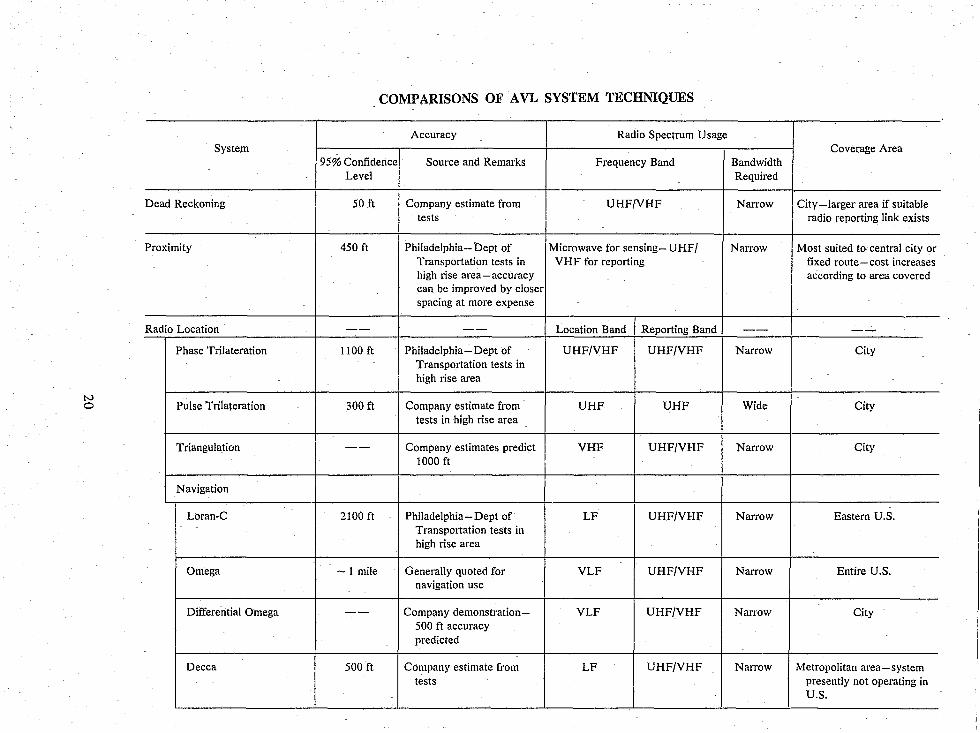
10. COMPARISONS OF AVL SYSTEM TECHNIQUES
Some of the pertinent information concerning parameters which vary among AVL systems is summarized in the following table. It is based on the most recent information available concemingtechnica1 characteristics. However, no police department operational experience with AVL systems in this country is yet available. For this reason it is too early to clearly define a system to meet particular requirements. Information obtained from pilot law enforcement studies is needed in order to make meaningful system comparisons.
19
N o
System
Dead Reckoning
Proximity
Radio Location
Phase Trilateration
Pulse Trilateration
Triangulation
Navigation
Loran-C
Omega
Differential Omega
Decca
COMPARISONS OF AVL SYSTEM TECHNIQUES
Accuracy Radio Spectrum Usage
95% Confidence Source and Remarks Frequency Band Level
50 ft Company estimate from UHF/VHF tests
450 ft Philadelphia - Dept of Microwave for sensing- UHF! Transportation tests in VHF for reporting high rise area-accuracy can be improved by closer spacing at more expense
-- -- Location Band I Reporting Band
1100 ft Philadelphia- Dept of UHF/VHF UHF/VHF Transportation tests in high rise area
300 ft Company estimate from UHF UHF tests in high rise area
-- Company estimates predict VHF UHF/VHF 1000 ft
2100ft Philadelphia-Dept of LF UHF/VHF Transportation tests in high rise area
-1 mile Generally quoted for VLF UHF/VHF navigation use
-- Company demonstration- VLF UHF/VHF 500 ft accuracy predicted
500 ft Company estimate from LF UHF/VHF tests
Coverage Area Bandwidth Required
Nan'ow City -larger area if suitable radio reporting link exists
Narrow Most suited to central city or fixed route-cost increases according to area covered
-- --Narrow City
Wide City
Narrow City
Narrow Eastern U.S.
Narrow Entire U.S.
Narrow City
Narrow Metropolitan area-system presently not operating in U.S.
ANNOTATED BIBLIOGRAPHY
The Challenge of Crime in a Free Society. A Report by the President's Commission on Law Enforcement and Administration of Justice, U.S. Government Printing Office, Feb. 1967.
Task Force Repor:: Science and Technology. A Report to the President's Commission on Law Enforcement and Administratio 1 of Justice, U.S. Government Printing Office, 1967. The first report above· ontains a general discussion of the crime problem in the U.S., including a chapter summarizing the conclusIons of the second report. The second report includes in Appendix E a discussion of car location systems and mobile digital communications with considerations relevant to standardization, entitled "Electronics Equipment Associated with the Police Car," by Raymond Knickel.
Propagation Young, Jr., W. R., "Comparison of Mobile Radio Transmission at 150,450,900, and 3700 Mc," The Bell
System Technical Journal, (Nov. 1952) pp. 1068-1085. Okumura, Y., Ohmori, E., Kauano, T., and Fukuda, K., "Field Strength and its Variability in VHF and
UHF Land-Mobile Radio Service," Review of the Electrical Communication Laboratory, Vol. 16, No. 9-10, (Sept.-Oct. 1968) pp. 825-873.
Black, D. M., and Rendink, D.O., "Some Characteristics of Mobile Radio Propagation at 836 MHz in the Philadelphia Area," IEEE Transactions on Vehicular Technology, Vol. VT-2I, No.2, (May 1972) pp. 45-51.
Cox, D. C., "Delay Doppler Characteristics of Multipath Propagation at 910 MHz in a Suburban Mobile Radio Environment," IEEE Transactions on Antennas and Propagation, Vol. AP-20, No.5, (Sept. 1972) pp.625-635.
Cox, D. C., "Time and Frequency-Domain Characteristics of MuItipatli Propagation at 910 MHz in a Suburban Mobile-Radio Environment," Radio Science, Vol. 7, No. 12, pp. 1069-1077.
Hefley, G., "The Development of Loran-C Navigation and Timing," Nat. Bur. Stand. (U.S.), Monogr. 129 (Oct. 1972). These papers present results of radio propagation experiments in urban environments.
Urban Propagation Models Applied to Vehicle Location Techniques Engel, J. S., "Effects of Multipath Transmission on the Measured Propagation Delay on an FM Signal,"
IEEE Transactions on Vehicular Technology, Vol. VT-18, No. I, (May 1969) pp. 44-52. Turin, G. L., Clapp, F. D., Johnston, T. L., Fine, S. B., and Lavry, D., "A Statistical Model of Urban
Multipath Propagation," IEEE Transactions on Vehicular Technology, Vol. VT-2I, No. I, (Feb. 1972) pp. 1-9.
Turin, G. L., Jewell, W. S., and Johnston, T. L., "Simulation of Urban Vehicle-Monitoring Systems,' IEEE Transactions on Vehicular Technology, Vol. VT -21, No. I, (Feb. 1972) pp. 9-16.
Sraras, H., and Honickman, S. N., "The Accuracy of Vehicle Location by Trilateration in a Dense Urban Environment," IEEE Transactions on Vehicular Technology, Vol. VT-21, No. I, (Feb. 1972) pp. 38-43. These papers use measured urban propagation data to develop propagation models from which vehicle location accuracy performance predictions are derived.
Radio Noise "World Distribution and Characteristics of Atmospheric Radio Noise," CCIR Report 322, International
Telecommunications Union, Geneva (1964). Disney, R. T., "Electromagnetic Interference from Man-Made Radio Noise Estimates of Business,"
Residential and Rural Area Characteristics. White, D. R. J., "Handbook on Electrical Noise and Electromagnetic Interference Specifications" (1971).
Details are given of mathematical descriptions of noise and methods for obtaining noise predictions.
Information Handling in Mobile Systems Cole, R. E., and Hanks, J. D., "Efficient Dispatching of Mobile Forces," IEEE Transactions on Vehicular
Technology, Vol. VT-18, No.1 (May 1969). Braun, W. V., and Walker, D. L., "Vehicular Location and Information Systems," IEEE Transactions on
Vehicular Technology, Vol. VT-19, No.1 (Feb. 1970). These papers discuss the kinds of information transfer that are needed with AVL and A VM systems and the application of digital techniques to information handling.
Vehicle Location System Technical Reports An Analytic and Experimental Evaluation of Alternative Methods for Automatic Vehicle Monitoring,
submitted to the Chicago Transit Authority and the U.S. Department of Transportation by the Institute of
21
Public Administration and Teknekron, Incorporated, July 1968. This report contains a detailed treatment of the three types of vehicle location methods with system analysis applicable to public transportation requirements.
Vehicle Location Study Phase 0 Report, task 1I9, Jet PropUlsion Laboratory, California Institute of Technology, Pasadena, California, March 1970. This report contains a detailed discussion and history of direction finding and navigation systems and techniques, as well as briefer treatment of the other methods.
Automatic Vehicle Monitoring Technology Review, S. H. Roth. Prepared for the Urban Mass Trar:sportation Administration, Department of Transportation, MTR 6059, August 1971. This report gives an extensive discussion of the three vehicle location methods including Department of Transportation requirements and background information for the Philadelphia A VL tests.
Vehicle Location and Status Reporting System (LOCATES), submitted to the California Council on Criminal Justice, Final Report, project number 182, March 1972. This reP9rt gives an extensive discussion of AVL systems, operations and demonstrations oriented toward police use in a small city, for the city of Montclair, California.
Urban Vehicle Monitoring: Technology Economics and Public Policy, in three volumes. Prepared by Teknekron, Inc., for the Office of Research and Technology, the U.S. Department of Housing and Urban Development. Vol. II, Technical Analysis and Appendices, contains an extensive technical discussion of A VL systems with results of experiments and computer simulation studies, including some cost estimates and description of possible display systems. Vol. III, Economic and Institutional Analysis and Appendices, discusses police operations with A VM applications and benefits, as well as other dispatched service discussions. It also considers markets, pricing structures, financing, and regulation and control issues. Vol. I, Summary Report, is a Sl!mmary of the other two reports including recommendations concerning government involvement in demonstration projects. Two major conclusions are that the benefits of A VM to police users are larger than for any other groups; and that joint user systems are necessary to reduce costs, economize on radio spectrum and insure system compatibility.
Urban Systems
Larson, R. C., "Urban Police Patrol Analysis" (the MIT Press, Cambridge, Massachusetts; and London, England, 1972). This book contains an extensive discussion of police patrol and dispatching, with applications of mathematical modeling techniques to these operations in order to make quantitative comparisons of various methods. It includes a chapter on evaluating the use of automatic car location systems.
22 U. s. GOVERNMENT PRINTING OFFICE: 1975 0 - 566-723