Embed Size (px)
Citation preview
i
AUTOMATIC TROLLEY HUMAN FOLLOWER
AMIR HAFIZUL BIN ABD MALEK
This Report Is Submitted In Partial Fulfillment of Requirement for the
Bachelor Degree of Electronic Engineering (Industrial Electronic) with Honours
Faculty of Electronic and Computer Engineering
Universiti Teknikal Malaysia Melaka
June 2014
ii
DECLARATION
“I declare that this report “Automatic Trolley Human Follower” is the result of my
own research except as cited in the references”
Signature : ……………………………………….
Author : AMIR HAFIZUL BIN ABD MALEK
Date : ……………………………………….
iii
“I hereby declare that I have read this report entitled “Automatic Trolley Human
Follower” and it fulfills the requirements of the scope and quality for the Bachelor of
Electronic Engineering (Industrial Electronic) with Honours”
Signature : ……………………………………………………...
Supervisor’s Name : ENGR. NAJMIAH RADIAH BINTI MOHAMAD
Date : ……………………………………………………...
iv
Special dedicate:
To my beloved mother Zainun Binti Ismail and my family for their loves and
prayers. To my supervisor and co-supervisor for their guide and give moral support
and then to my entire friend for their help and advice.

v
ACKNOWLEDGEMENT
I would like to express my gratitude and appreciation to all those who gave
me the support to complete this “Automatic Human Follower trolley” thesis. A
special thanks to my final year project supervisor Madam Najmiah Radiah Binti
Mohamad who give suggestion and encouragement, helped me to coordinate my
project especially in writing this report.
I would like to acknowledge with much appreciation the crucial role of staff
of laboratory, who gave the permission to use all required machinery and the
necessary material to complete this project.
Lastly, I would like to thank my parents and my family members for bearing
my absence for 4 year. I wholeheartedly thank all of them for sending me abundant
love, encouragement and support all the way from home their hearts.
vi
ABSTRACT
This project has successfully produced an Automatic Trolley Human
Follower for general or industrial user. An automatic trolley human follower is
developed to help a user or production industry to reduce the utilization of human
energy in order to carry heavy things. This automatic trolley human follower is
controlled by a PIC 16F877A microcontroller that can follow the user automatically
with integrated circuit of ultrasonic and IR sensor. The 12V DC motor was used as
the power supplied to move the trolley automatically follow a user in hypermarket or
industrial use. In this project a robotic vehicle is fabricated which runs like a regular
trolley by carrying tools from place to another. This is done by using a set of receiver
and transmitter ultrasonic sensor to detect a user in a 1 meter range and it will follow
the user. Ultrasonic receiver will be placed on the user belt and it transmitter placed
in the body of trolley while IR sensor is use to detect an obstacle and completely to
trace a user in range 1 meter. The sensitivity of the IR Sensor to detect the blocking
object was different based on color. The average distance for bright object detected is
34.7cm while for dark color is 15.2cm. However this trolley has second mode
function which can be manually controlled by radio frequency remote control if the
automatic was not properly function in the limited space. The Automatic Trolley
Human Follower was designed with dimension of sizes 75cm length, 50cm width
and 60cm height. The maximum loads that can be carrying by the trolley are 120kg
with speed of 13cm/s.
vii
ABSTRAK
Projek ini berjaya menghasilkan sebuah troli pengikut manusia secara
automatik untuk kegunaan asas dan kegunaan dalam industri. Troli pengikut manusia
secara automatic dihasilkan untuk membantu pengguna dan pihak industri untuk
mengurangkan tenaga kerja manusia untuk mengangkat barang berat. Troli ini
dikawal oleh PIC 16F877A mikrokontroler yang membolehkan mengikut manusia
dengan bantuan ultrasonik dan IR sensor. Oleh itu, dengan menggabungkan
ultrasonik dan IR sensor sebagai input dan 12V DC Motor sebagai output yang
dikawal oleh mikrokontroller troli itu boleh mengekori pengguna di dalam pasar raya
atau dalam industri. Dalam projek ini, kenderaan robotik adalah rekaan yang
berjalan seperti troli biasa dengan membawa barang dari satu tempat ke satu tempat
yang lain. Ini dilakukan dengan menggunakan satu set penerima dan pemancar
sensor ultrasonik untuk mengesan pengguna dalam julat 1 meter dan ia akan
mengikut pengguna. Penerima ultrasonik akan diletakkan pada tali pinggang dan
pemancar diletak pada troli. IR sensor digunakan untuk mengesan halangan dan
mengesan pengguna pada jarak 1 meter. Sensitiviti IR Sensor berbeza mengikut
warna objek yang dikenalpasti. Purata jarak objek berwarna cerah yang dikenalpasti
oleh IR Sensor adalah 34.7cm dan untuk objek gelap adalah 15.2cm.Walau
bagaimanapun troli ini mempunyai fungsi mod kedua yang boleh dikawal secara
manual dengan frekuensi radio kawalan jauh jika automatik mod tidak berfungsi
dalam ruang yang terhad. Dimensi ukuran Automatic Trolley Human Follower
adalah panjang 75cm, lebar 50cm dan tinggi 60cm. Beban maksimum yang boleh
dibawa oleh troli adalah 120kg dengan kelajuan 13cm/s.
viii
TABLE OF CONTENTS
CHAPTER TITLE PAGES
TITLE PAGE i
DECLARATION iii
DEDICATION v
ACKNOWLEDGEMENT vi
ABSTRACT vii
ABSTRAK viii
TABLE OF CONTENTS ix
LIST OF TABLES xiii
LIST OF FIGURES xiv
LIST OF ABBREVIATIONS xvii
I INTRODUCTION
1.1 Introduction 1
1.2 Problem Statement 2
1.3 Objectives 2
1.4 Scope of the project 3
II LITERATURE REVIEW
2.1 Introduction 4
2.1.1 Radio Frequency based Remote 4
Operated SPY Robot
2.1.2 A Mini Forklift Robot 5
2.1.3 Human Leader and Robot Follower 6
ix
Team
2.1.4 Infrared Sensor Based Target 7
Following Device for a Mobile Robot
2.1.5 Detecting and Tracking People 8
by Mobile Robot Using Structured
Light Range Sensor
2.1.6 Robot Tracking Using Vision and 9
III METHODOLOGY
3.1 Introduction 10
3.2 Illustration of Project Design 11
3.3 Overview of the Project Development 12
3.4 Project Operation 13
3.4.1 Automatic Mode 13
3.4.2 Manually Mode 16
3.5 Circuit Design 19
3.5.1 Ultrasonic Transmitter Module Design 19
3.5.2 Ultrasonic Receiver Module Design 20
3.5.3 Infra Red (IR) Module Design 22
3.5.4 Motor Drive Module Design 22
3.5.5 Main Microcontroller Module Design 25
IV RESULT AND DISCUSSION
4.1 Introduction 27
4.2 Hardware Result 27
4.2.1 Trolley Design Measurement Frame 27
4.2.2 Main circuit Result 28
x
4.2.3 Relay circuit result 29
4.2.4 Ultrasonic Sensor Result 31
4.2.5 IR Sensor Result 32
4.2.6 Radio Frequency Remote Control Result 34
4.3 Measurements of IR Sensor 34
4.4 Measurements the Speed of the Trolley 35
4.4.1 Measurement the Speed of the Trolley in 36
Straight Line
4.5 Discussion and Analysis 37
4.5.1 Analysis of IR Sensor Result 37
4.5.2 Analysis of the Speed of the Trolley Due 37
To the Load
V CONCLUSION AND RECOMENDATION
5.1 Conclusion 39
5.2 Recommendation 40
REFERENCES
APPENDIX A (Coding)
APPENDIX B (Datasheet)
xi
LIST OF TABLES
NO TITLE PAGES
4.1 Data Distance of Infrared Sensor Based On Color 35
4.2 Data for the Speed of the Trolley in Straight Line 36
xii
LIST OF FIGURES
NO TITLE PAGES
2.1 Radio Frequency based Remote Operated SPY Robot 5
2.2 Design of Forklift Robot 6
2.3 Human Leader and Robot Follower Concept 7
2.4 IR Sensor Range 7
2.5 Mobile Robot Using Structured Light Range Sensor 8
2.6 Robot Tracking Following a Person 9
3.1 Illustration Version of trolley design 11
3.2 A System Flow 12
3.3 Overview of project operation (automatic mode) 13
3.4 Flowchart of project operation (automatic mode) 14
3.5 Overview of project operation (manually mode) 16
3.6 Flowchart of project operation (manually mode 17
3.7 Schematic of ultrasonic transmitter 19
3.8 PCB Wizard Circuit of ultrasonic transmitter 20
3.9 Schematic Circuit of ultrasonic receiver 21
3.10 PCB Wizard Circuit of ultrasonic receiver 21
3.11 Schematic circuit of infra red 22
3.12 Schematic Circuit of 5V motor drive 23
3.13 PCB Wizard Circuit of 5V motor drive 23
3.14 Schematic Circuit of 12V motor drive 24
xiii
3.15 PCB Wizard Circuit of 12V motor drive 24
3.16 Schematic circuit of PIC 25
3.17 PCB Wizard circuit of PIC 25
4.1 Measurement Frame of the Trolley 28
4.2 Main circuit with PIC microcontroller 29
4.3 12V Relay Circuit 30
4.4 5V Relay Circuit 30
4.5 Ultrasonic Receiver Circuits 31
4.6 Ultrasonic Transmitter 32
4.7 IR Sensor Circuit 33
4.8 IR Sensor Comparator Circuit 33
4.9 RF Remote Control module Circuit 34
4.10 Graph of the Speed of Trolley Vs the Load 38
xiv
LIST OF ABBREVIATIONS
DC - Direct Current
IC - Integrated Circuit
IR - Infrared
PIC - Peripheral interface controller
PTZ - Pant-Tilt-Zoom
RFID - Radio Frequency Identification Device
SL - Structured Light
UART - Universal Asynchronous Receiver/ Transmit
1
CHAPTER I
INTRODUCTION
1.1 Introduction
Nowadays, most of the things in this world use the technology for more
productive life. The people always find something to help them doing a works rather
doing them self because of their busy life. However, this new technology which is
designed for shopping or carrying heavy thing has never used before. Trolley is a
large metal basket or frame on wheels is used for transporting heavy or large items,
such as supermarket purchases or luggage at an airport or railway station and
transferring a heavy item in industry. By using a trolley, humans do not need to feel
bothered and will not get tired for carrying goods although it are quite lot. In manual
trolley, human labor is still required to utilize trolley. They still need to push the
trolley or bring the basket to bring the stuff. So, if there is a trolley that can be run
automatically, then bring the stuff will be easier and efficient.
After making observation and thinking some idea, a decision to build an
Automatic Trolley Human Follower for general or industrial user has been make.
This Automatic Trolley Human Follower is combination of general trolley with
concept human follower robot. Robots can support humans in complex everyday
tasks, such as indoor and outdoor navigation and information supplying, or carrying
heavy objects [1].The purpose of designing this project is to help shopping
management or industry to use this tool as a commitment to improved quality of
service and work.
2
1.2 Problem Statement
From the observation on retail and industrial sector, there is a lot of people in
Malaysia are still using manual trolley to carry heavy thing. Most of them do not
expose to an automatic trolley technology for replacing existing tools and improve
the quality of services. Accordingly, these technologies have been establish to
carrying tools that too heavy, that its uses a lot of energy to push the trolley [2].
The innovation of automatic trolley can evade from injury to user because
repetitive or sustained awkward posture when handling trolley can cause injury [2].
Furthermore, the manual trolley is not user friendly to pregnant woman and disables
people. There was an accident involved uncontrolled trolley which one old woman
died in China because of that manual trolley was slides down form an escalator [3].
1.3 Objectives
The main objectives of this project are
i. To design and produce a versatile trolley that is user friendly for
human and makes their life more productive.
ii. To produce automatic trolley that can carry a heavy thing to move
from one point to another point.
1.4 Scope of Project
3
This project is focusing a trolley that can be use in hypermarket or industries
that automatically follow the user to shopping and carry thing. The versatile design
of this trolley can be transform into two versions.
This Automatic Trolley Human Follower target is general user and industry
uses. For general user, this trolley are focusing to help a user when they are shopping
in hypermarket .The user does not need to worry about the trolley that carry their
items and they can focus on their shopping. The trolley can follow the user in
specific range and it not follows the user too close.
For the industrial use, the target point is to help industry that need carry
heavy tools to move from one point to another point. This trolley can thus reduce the
manpower. When their need to carry a heavy tools, it can be handled just by one
labor because this trolley can follow the labor. So, It can reduce the cost of workers
hired.
The versatile design of trolley can help workers carry up to 100kg of thing.
The Automatic Trolley Human Follower was designed using 4 wheel trolleys and
focusing on back wheel that connect 12 volt dc motor to move on the trolley. The
trolley distance about 0.5 meters from user or obstacle. The process to the overall for
this robot is controlled and setting by the PIC 16F877A.
The trolley is also design with manually mode by using Radio Frequency
(RF) Remote Control to perform when the automatic mode was broken. There are
four buttons to control the movement of the trolley. The button A is for move
Forward to The Right, button B is for Backward Right, C for Forward Left and D for
Backward Left.
4
CHAPTER II
LITERATURE REVIEW
2.1 INTRODUCTION
By design the suitable Automatic Trolley Human Follower for the
applications that desired, the decision has been made from a combination of some
robots follower that has nowadays with a manual trolley that existing. These are
some robots followers that have a guideline to design the Automatic Trolley Human
Follower.
2.1.1 Radio Frequency based Remote Operated SPY Robot
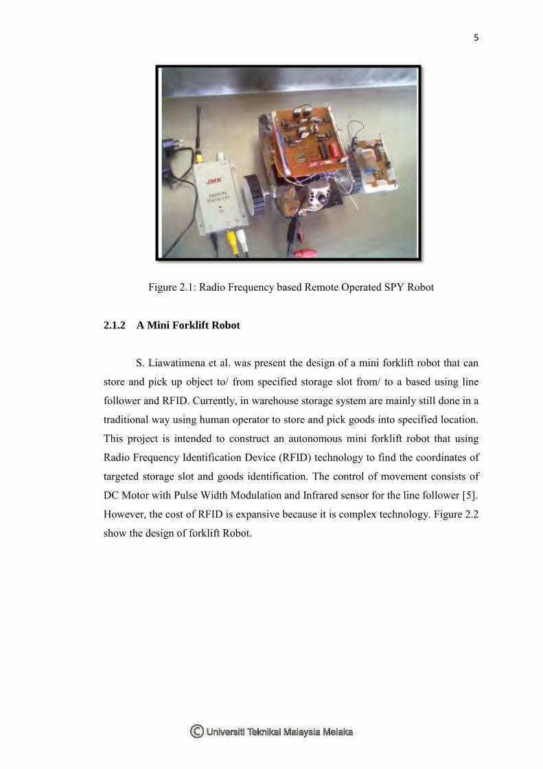
T. Krishnan et al. were creating a Radio Frequency based Remote Operated
SPY Robot. It is a remote operated spy robot circuit which can be controlled by
using a wireless remote controller. It can capture audio and video information’s from
the surroundings and can be sent to a remote station through RF signals [4]. This
robot was creating to spy and capture audio but the concept of RF Remote Controller
can be used to the Automatic Human Following Robot. Figure 2.1 was show the
Radio Frequency based Remote Operated SPY Robot.
5
Figure 2.1: Radio Frequency based Remote Operated SPY Robot
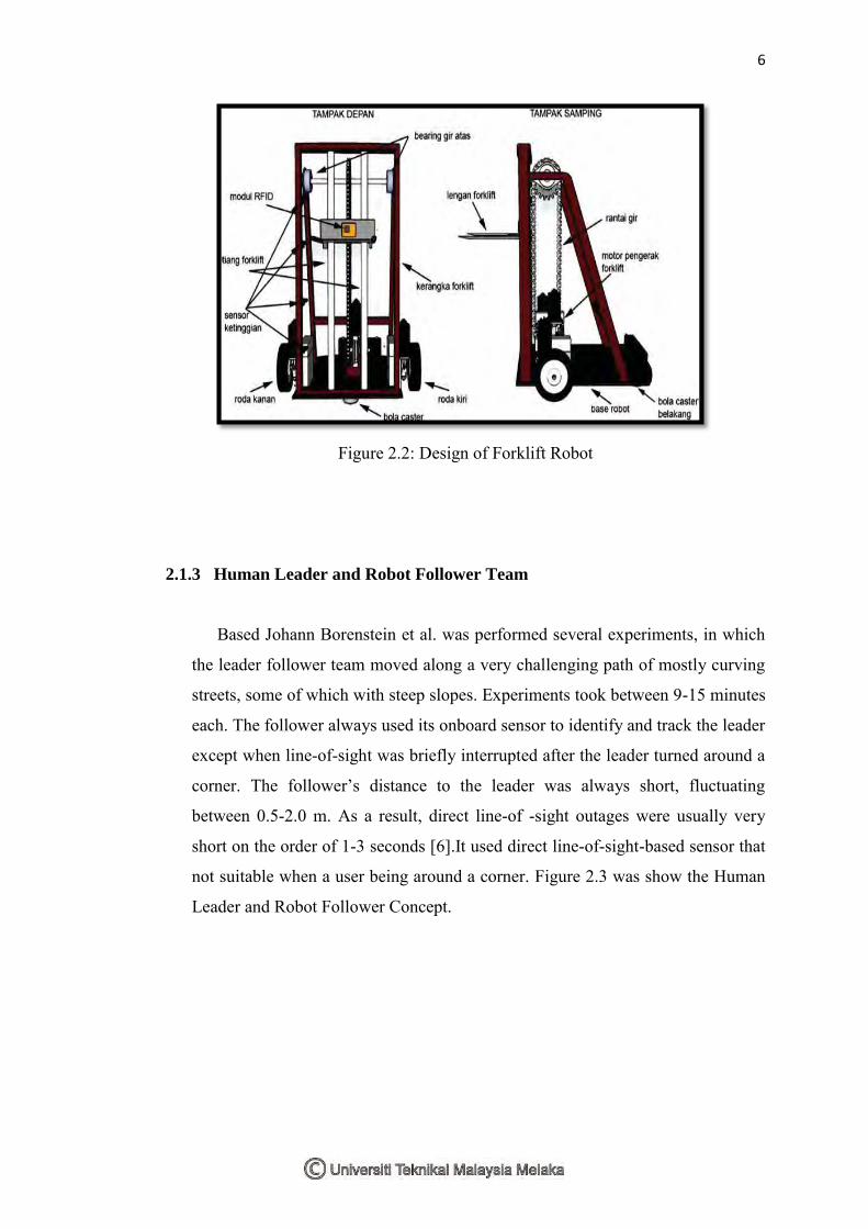
2.1.2 A Mini Forklift Robot
S. Liawatimena et al. was present the design of a mini forklift robot that can
store and pick up object to/ from specified storage slot from/ to a based using line
follower and RFID. Currently, in warehouse storage system are mainly still done in a
traditional way using human operator to store and pick goods into specified location.
This project is intended to construct an autonomous mini forklift robot that using
Radio Frequency Identification Device (RFID) technology to find the coordinates of
targeted storage slot and goods identification. The control of movement consists of
DC Motor with Pulse Width Modulation and Infrared sensor for the line follower [5].
However, the cost of RFID is expansive because it is complex technology. Figure 2.2
show the design of forklift Robot.
6
Figure 2.2: Design of Forklift Robot
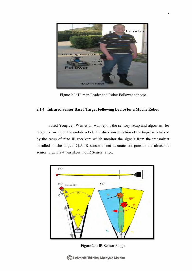
2.1.3 Human Leader and Robot Follower Team
Based Johann Borenstein et al. was performed several experiments, in which
the leader follower team moved along a very challenging path of mostly curving
streets, some of which with steep slopes. Experiments took between 9-15 minutes
each. The follower always used its onboard sensor to identify and track the leader
except when line-of-sight was briefly interrupted after the leader turned around a
corner. The follower’s distance to the leader was always short, fluctuating
between 0.5-2.0 m. As a result, direct line-of -sight outages were usually very
short on the order of 1-3 seconds [6].It used direct line-of-sight-based sensor that
not suitable when a user being around a corner. Figure 2.3 was show the Human
Leader and Robot Follower Concept.
7
Figure 2.3: Human Leader and Robot Follower concept
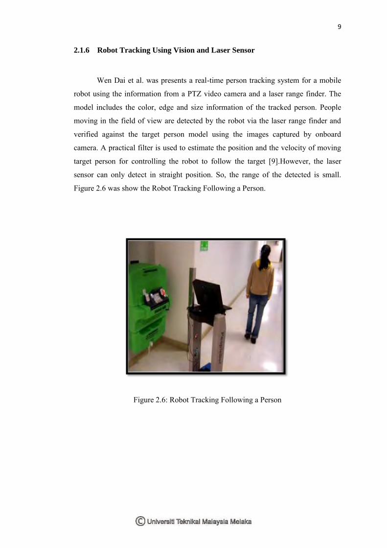
2.1.4 Infrared Sensor Based Target Following Device for a Mobile Robot
Based Youg Jen Wen et al. was report the sensory setup and algorithm for
target following on the mobile robot. The direction detection of the target is achieved
by the setup of nine IR receivers which monitor the signals from the transmitter
installed on the target [7].A IR sensor is not accurate compare to the ultrasonic
sensor. Figure 2.4 was show the IR Sensor range.
Figure 2.4: IR Sensor Range

8
2.1.5 Detecting and Tracking People by Mobile Robot Using Structured Light
Range Sensor
In Young jinn Hong et al. was introduced a home robot to keep track of
moving people in home environments. A SL range sensor is utilized in light of its
high commercial viability. The sensors typically have relatively short measurement
range and poor range resolution at a long distance (within 4 meters in our case).
These shortcomings raise some problems that feature detection process gives many
human legs candidates making it difficult to discriminate the real human legs from
other patterns [8].The sensors typically have relatively short measurement range and
poor range resolution at a long distance. Figure 2.5 show the Mobile Robot Using
Structured Light Range Sensor.
Figure 2.5: Mobile Robot Using Structured Light Range Sensor
9
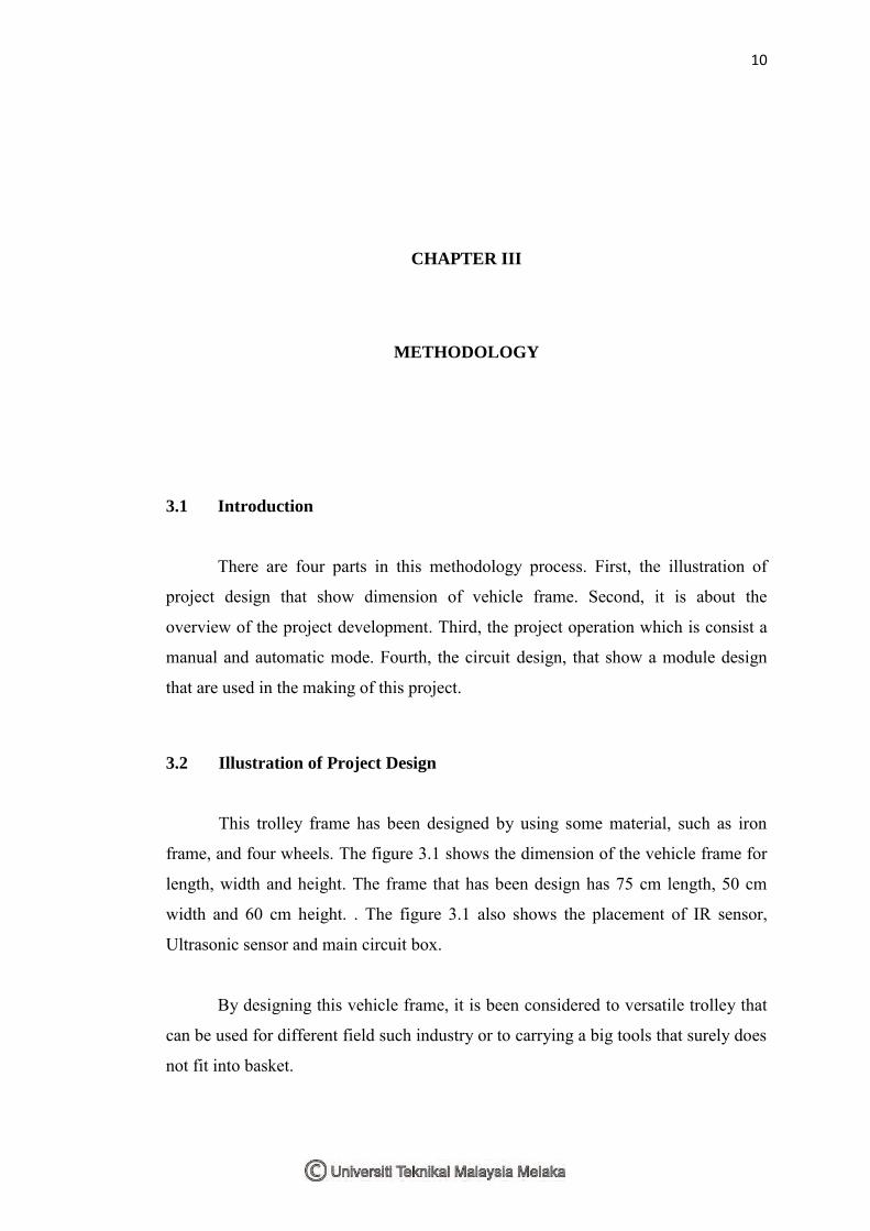
2.1.6 Robot Tracking Using Vision and Laser Sensor
Wen Dai et al. was presents a real-time person tracking system for a mobile
robot using the information from a PTZ video camera and a laser range finder. The
model includes the color, edge and size information of the tracked person. People
moving in the field of view are detected by the robot via the laser range finder and
verified against the target person model using the images captured by onboard
camera. A practical filter is used to estimate the position and the velocity of moving
target person for controlling the robot to follow the target [9].However, the laser
sensor can only detect in straight position. So, the range of the detected is small.
Figure 2.6 was show the Robot Tracking Following a Person.
Figure 2.6: Robot Tracking Following a Person
10
CHAPTER III
METHODOLOGY
3.1 Introduction
There are four parts in this methodology process. First, the illustration of
project design that show dimension of vehicle frame. Second, it is about the
overview of the project development. Third, the project operation which is consist a
manual and automatic mode. Fourth, the circuit design, that show a module design
that are used in the making of this project.
3.2 Illustration of Project Design
This trolley frame has been designed by using some material, such as iron
frame, and four wheels. The figure 3.1 shows the dimension of the vehicle frame for
length, width and height. The frame that has been design has 75 cm length, 50 cm
width and 60 cm height. . The figure 3.1 also shows the placement of IR sensor,
Ultrasonic sensor and main circuit box.
By designing this vehicle frame, it is been considered to versatile trolley that
can be used for different field such industry or to carrying a big tools that surely does
not fit into basket.