Embed Size (px)
Citation preview
IL14001
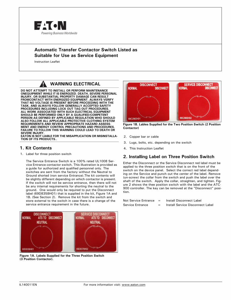
Automatic Transfer Contactor Switch Listed as Suitable for Use as Service EquipmentInstruction Leaflet
1EN For more information visit: www.eato
1. Kit Contents1. Label for three position switch
The Service Entrance Switch is a 100% rated UL1008 Ser-vice Entrance contactor switch. This illustration is provided as a guide for authorized and qualified personnel only. The switches are sent from the factory without the Neutral to Ground shorted (non service Entrance).The kit contents will be slightly different depending on which contactor is present. If the switch will not be service entrance, then there will not be any internal requirements for shorting the neutral to the ground. One would only be required to put the Disconnect label (69D8358H01) that is supplied in the kit, Figure 1A and 1B. (See Section 2). Remove the kit from the switch and store external to the switch in case there is a change of the service entrance requirement in the future.
Figure 1A. Labels Supplied for the Three Position Switch (3 Position Contactor).
WARNING ELECTRICALDO NOT ATTEMPT TO INSTALL OR PERFORM MAINTENANCE ONEQUIPMENT WHILE IT IS ENERGIZED. DEATH, SEVERE PERSONAL INJURY, OR SUBSTANTIAL PROPERTY DAMAGE CAN RESULT FROMCONTACT WITH ENERGIZED EQUIPMENT. ALWAYS VERIFY THAT NO VOLTAGE IS PRESENT BEFORE PROCEEDING WITH THE TASK, AND ALWAYS FOLLOW GENERALLY ACCEPTED SAFETY PROCEDURES INCLUDING LOCK OUT TAG OUT PROCEDURES. ALL WORK ASSOCIATED WITH SUCH ELECTRICAL EQUIPMENT SHOULD BE PERFORMED ONLY BY A QUALIFIED/COMPETENT PERSON AS DEFINED BY APPLICABLE REGULATION WHO SHOULD ALSO FOLLOW ALL APPLICABLE PROTECTIVE CLOTHING SYSTEM REQUIREMENTS AND REVIEW APPROPRIATE HAZARD ASSESS-MENT AND ENERGY CONTROL PRECAUTIONS AND PROCEDURES. FAILURE TO FOLLOW THIS WARNING COULD LEAD TO DEATH OR SEVERE INJURY.EATON IS NOT LIABLE FOR THE MISAPPLICATION OR MISINSTALLA-TION OF ITS PRODUCTS..
Figure 1B. Lables Supplied for the Two Position Switch (2 Position Contactor)
2. Copper bar or cable
3. Lugs, bolts, etc. depending on the switch
4. This Instruction Leaflet
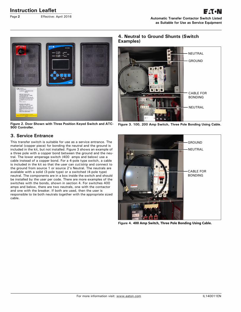
2. Installing Label on Three Position SwitchEither the Disconnect or the Service Disconnect red label must be applied to the three position switch that is on the front of the switch on the device panel. Select the correct red label depend-ing on the Service and punch out the center of the label. Remove (un-screw) the collar from the switch and push the label over the shaft of the switch. Apply the collar, straighten, and tighten. Fig-ure 2 shows the thee position switch with the label and the ATC-900 controller. The key can be removed at the "Disconnect" posi-tion.
Not Service Entrance = Install Disconnect LabelService Entrance = Install Service Disconnect Label
n.com
Instruction LeafletPage 2 Effective: April 2016 Automatic Tran
as Suitable f
Figure 2. Door Shown with Three Position Keyed Switch and ATC-900 Controller.
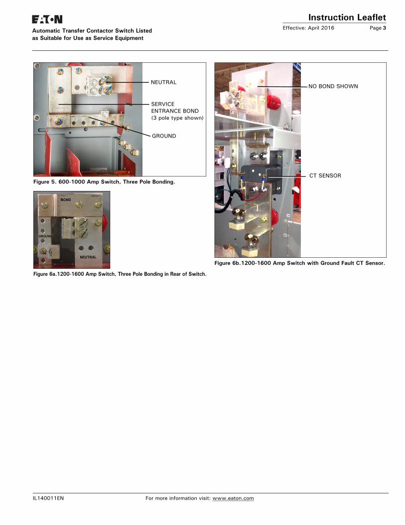
3. Service EntranceThis transfer switch is suitable for use as a service entrance. The material (copper piece) for bonding the neutral and the ground is included in the kit, but not installed. Figure 3 shows an example of a three pole with a copper bond between the ground and the neu-tral. The lower amperage switch (400 amps and below) use a cable instead of a copper bond. For a 4-pole type switch, a cable is included in the kit so that the user can cut/strip and connect to the ground from source 1 or source 2's Neutral. The neutrals are available with a solid (3-pole type) or a switched (4-pole type) neutral. The components are in a box inside the switch and should be installed by the user per code. There are more examples of the switches with the bonds, shown in section 4. For switches 400 amps and below, there are two neutrals, one with the contactor and one with the breaker. If both are used, then the user is responsible to tie both neutrals together with the appropriate sized cable.
4. Neutral to Ground Shunts (Switch Examples)
Figure 3. 100, 200 Amp Switch, Three Pole Bonding Using Cable.
Figure 4. 400 Amp Switch, Three Pole Bonding Using Cable.
NEUTRAL
GROUND
CABLE FORBONDING
NEUTRAL
GROUND
NEUTRAL
CABLE FORBONDING
For more information visit: www.eaton.com
sfer Contactor Switch Listedor Use as Service Equipment
IL140011EN
Instruction LeafletEffective: April 2016 Page 3Automatic Transfer Contactor Switch Listed
Figure 5. 600-1000 Amp Switch, Three Pole Bonding.
Figure 6a.1200-1600 Amp Switch, Three Pole Bonding in Rear of Switch.
Figure 6b.1200-1600 Amp Switch with Ground Fault CT Sensor.
NEUTRAL
SERVICE
GROUND
ENTRANCE BOND(3 pole type shown)
NO BOND SHOWN
CT SENSOR
IL140011EN For more information visit: www.eaton.com
as Suitable fo
r Use as Service Equipment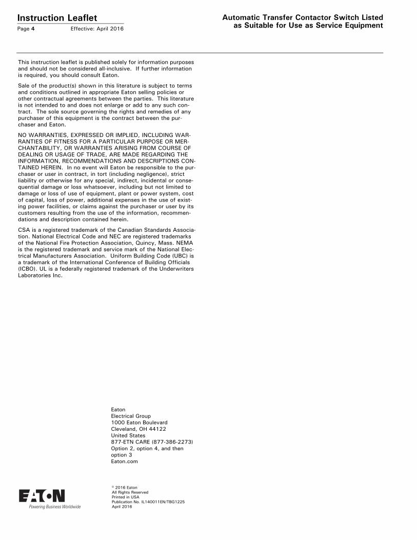
Instruction LeafletPage 4 Effective: April 2016
Automatic Transfer Contactor Switch Listedas Suitable for Use as Service Equipment
This instruction leaflet is published solely for information purposes and should not be considered all-inclusive. If further information is required, you should consult Eaton.
Sale of the product(s) shown in this literature is subject to terms and conditions outlined in appropriate Eaton selling policies or other contractual agreements between the parties. This literature is not intended to and does not enlarge or add to any such con-tract. The sole source governing the rights and remedies of any purchaser of this equipment is the contract between the pur-chaser and Eaton.
NO WARRANTIES, EXPRESSED OR IMPLIED, INCLUDING WAR-RANTIES OF FITNESS FOR A PARTICULAR PURPOSE OR MER-CHANTABILITY, OR WARRANTIES ARISING FROM COURSE OF DEALING OR USAGE OF TRADE, ARE MADE REGARDING THE INFORMATION, RECOMMENDATIONS AND DESCRIPTIONS CON-TAINED HEREIN. In no event will Eaton be responsible to the pur-chaser or user in contract, in tort (including negligence), strict liability or otherwise for any special, indirect, incidental or conse-quential damage or loss whatsoever, including but not limited to damage or loss of use of equipment, plant or power system, cost of capital, loss of power, additional expenses in the use of exist-ing power facilities, or claims against the purchaser or user by its customers resulting from the use of the information, recommen-dations and description contained herein.
CSA is a registered trademark of the Canadian Standards Associa-tion. National Electrical Code and NEC are registered trademarks of the National Fire Protection Association, Quincy, Mass. NEMA is the registered trademark and service mark of the National Elec-trical Manufacturers Association. Uniform Building Code (UBC) is a trademark of the International Conference of Building Officials (ICBO). UL is a federally registered trademark of the Underwriters Laboratories Inc.
April 2016
© 2016 Eaton All Rights ReservedPrinted in USAPublication No. IL140011EN/TBG1225
Eaton Electrical Group1000 Eaton BoulevardCleveland, OH 44122United States877-ETN CARE (877-386-2273)Option 2, option 4, and then option 3Eaton.com