Embed Size (px)
Citation preview
Vol-4 Issue-2 2018 IJARIIE-ISSN(O)-2395-4396
8300 www.ijariie.com 4284
AUTOMATIC SHUTTER LIFTING
MACHINE BY USING BEVEL GEAR
WITH REMOTE CONTROL K. VENGATESVARAN
1, M. ELANGO
2, R JAYAPRAKESH
3, R.SANTHIYA
4, S.K.
MALATHI5
1Assistant Professor, Department of Mechanical Engineering, Gnanamani College of Technology,
Namakkal 2,3,4,5
BE, Department of Mechanical Engineering, Gnanamani College of Technology, Namakkal.
ABSTRACT The ultimate purpose of this project is to develop a remote controlled rolling shutter using a sensor .
In this project the main objective is the shutter operate as manual and also motor , This is two in one process. In
the project the bevel gear mechanism is used to sensor this type is INFRARED. This remote control is used to
ON-OFF the motor. The final outcomes the project is the running the shutter using remote control . The scope
of the project is to reduce the manual work and human injuries due to shutter operation.
Keywords: Infrared sensor, human fatigue, bevel gear, roller shutter
1. INTRODUCTION:
A roller shutter, roller door, sectional over head door is a type of door or window consisting of
many horizontal slats (or sometimes bars or web system) hinged together. The shutter is raised to open it
and lower to closed it. In this shutter operation is may controlled in motorized and using sensor with the
advancement in technology, manual shutters have been upgraded to automatic roll-up shutters. The uses of
remote controlled roller shutters in industries have made opening and closing of shutters easy. Our design
provides additional features like the use of sensor (Infrared) in order to reducing number of accidents
occurring due to mechanism failure. The remote control rolling shutter finds applications garages, banks in
field of military applications i.e. ammunition ware house, industries and ministries and nuclear power
plants etc.
1.1 NEED FOR AUTOMATION:
Automation can be achieved through computers, hydraulics, pneumatics, robotics, etc., of these sources,
pneumatic form an attractive medium for low cost automation. The main advantage of all pneumatic
systems are economy and simplicity. Automation plays an important role in mass production. Nowadays
almost all the manufacturing process is being made automatic in order to deliver the products at a faster
rate. The following reasons affirms the benefits of automation.
To achieve mass production
To reduce man power
To increase the efficiency of man power
To reduce the work load
To reduce the production cost
To reduce the production time
To reduce the material handling
To reduce the fatigue of workers
To achieve the god quality
Less maintenance
Vol-4 Issue-2 2018 IJARIIE-ISSN(O)-2395-4396
8300 www.ijariie.com 4285
2. LITERATURE REVIEW Ekejiuba CO , Folayan GB ‘Remote controlled security door’ to performing the security door controlled
by remote control by using a microprocessor control unit and using the sensor control.
Kushali Sindhia , Mathumitha Prakash , S.V.Sathish ‘ Design of smart rolling shutters for low cost
operations’ to design the smart rolling shutters and operate the shutters by the performance of motor and
piezoelectric sensor.
Benmabrouk. Zaineb , Ben Hamed. Mouna, Lassaad. Sbita ‘ Wireless control for an induction motor’
to discuss the development of wireless structure control of an induction motor scalar drives. This was
realized up on the wireless wifi networkes.
Ayodele Sunday Oluwole , Temitope Adefarati , Kehinde Olusyi , Adedayo Babarinde , Ezea Hillary
‘ Design of automatic gate control using infrared remote with password protected features’ to Infrared or
wireless technology provides an alternate, more portable, more independent means of accessing, opening
and closing of a and other electronic information. This research examines how user can open and close the
gate with using of IR control.
Trupti S Bobade , Anushri S. sathiskar , Anushri S. Garud , U. W. Kaware , R.K. Dehankar ‘
Induction motor speed control using android applications’ to proposed system designed to controlling the
speed of induction motor using android applications where the remotely controlling the speed of induction
motor is achieved.
T. Appa Rao , Madhu Kumari , Mayank Kumar , Manoranjan Gopal Priya ‘Thyristor controlled
power of induction motor by IR remote’ The speed control scheme design and implementation of speed
control of induction motor through infrared receiver remote is presented. This design is used to control AC
power of the different load by using firing angle control by thyristor.
Dokhe Anitha Dattatraya , N.D.Kapale , D.N.Kyatanavar ‘ Gesture recognition based AC motor speed
control’ to the experimental results are highly encouraging as the system is able to produces real-time
responses and accurate recognition towards various set of gestures to performing the respective task.
3. OBJECTIVE AND METHODOLOGY
3.1 OBJETIVE:
The objective of the present work is to evaluate performance characteristics on A.C induction motor run on
the rolling shutter.
To prepare a sensor control circuit board.
To analyse the properties of the rolling shutter.
Conducting the experiments with necessary equipment to study the performance characteristics rolling
shutter using the prepared remote controlled sensor.
To compare the performance characteristics of rolling shutter prepared remote control sensor.
To prepare the manual shutter gear box.
3.2 METHODOLOGY:
The modular method is employed with a design. The design involves two parts; the hardware and manual
parts.
3.2.1 HARDWARE DESIGN:
The hardware part is designed to drive the induction motor for the required application in forward and
reversed directions using wireless technology. The proposed system demonstrates a technology to rotate a
squirrel cage induction motor in both clockwise and counter clock wise direction. It also has a provision to
control the direction of the motor using an IR remote.
When the remote button is pressed, it sends an IR signal in RC5 code which is received by an IR receiver
called TSOP-1738. Output from the receiver fed to a micro controller of 8051family infrared to a relay driver
IC.
3.2.2 MANUAL DESIGN:
The manual is designed in order to support the effectiveness of the hardware device. The complex and intricate
operating routine of the manual is achieved by handle the performance to gearbox. To using of the handler using
the performance on the forward and reversed motion and finally shutter rotates upper and downward motion.
Vol-4 Issue-2 2018 IJARIIE-ISSN(O)-2395-4396
8300 www.ijariie.com 4286
4. COMPONENT SELECTION
4.1 MOTOR:
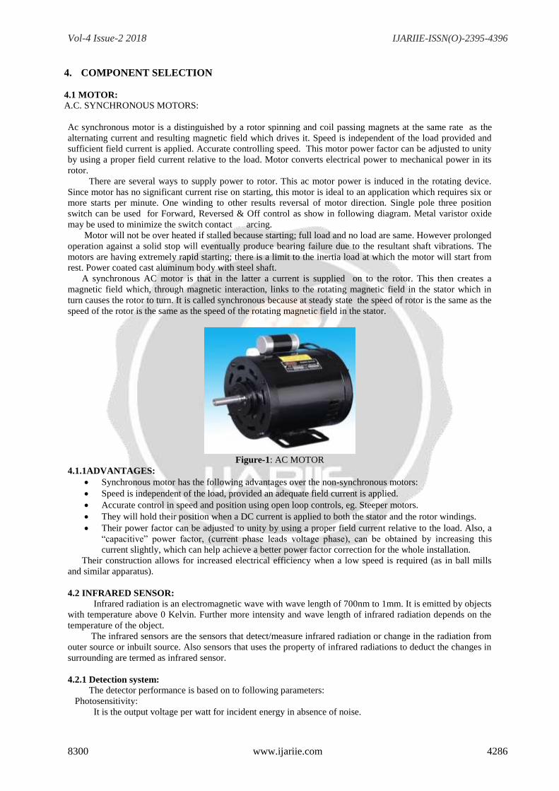
A.C. SYNCHRONOUS MOTORS:
Ac synchronous motor is a distinguished by a rotor spinning and coil passing magnets at the same rate as the
alternating current and resulting magnetic field which drives it. Speed is independent of the load provided and
sufficient field current is applied. Accurate controlling speed. This motor power factor can be adjusted to unity
by using a proper field current relative to the load. Motor converts electrical power to mechanical power in its
rotor.
There are several ways to supply power to rotor. This ac motor power is induced in the rotating device.
Since motor has no significant current rise on starting, this motor is ideal to an application which requires six or
more starts per minute. One winding to other results reversal of motor direction. Single pole three position
switch can be used for Forward, Reversed & Off control as show in following diagram. Metal varistor oxide
may be used to minimize the switch contact arcing.
Motor will not be over heated if stalled because starting; full load and no load are same. However prolonged
operation against a solid stop will eventually produce bearing failure due to the resultant shaft vibrations. The
motors are having extremely rapid starting; there is a limit to the inertia load at which the motor will start from
rest. Power coated cast aluminum body with steel shaft.
A synchronous AC motor is that in the latter a current is supplied on to the rotor. This then creates a
magnetic field which, through magnetic interaction, links to the rotating magnetic field in the stator which in
turn causes the rotor to turn. It is called synchronous because at steady state the speed of rotor is the same as the
speed of the rotor is the same as the speed of the rotating magnetic field in the stator.
Figure-1: AC MOTOR
4.1.1ADVANTAGES:
Synchronous motor has the following advantages over the non-synchronous motors:
Speed is independent of the load, provided an adequate field current is applied.
Accurate control in speed and position using open loop controls, eg. Steeper motors.
They will hold their position when a DC current is applied to both the stator and the rotor windings.
Their power factor can be adjusted to unity by using a proper field current relative to the load. Also, a
“capacitive” power factor, (current phase leads voltage phase), can be obtained by increasing this
current slightly, which can help achieve a better power factor correction for the whole installation.
Their construction allows for increased electrical efficiency when a low speed is required (as in ball mills
and similar apparatus).
4.2 INFRARED SENSOR:
Infrared radiation is an electromagnetic wave with wave length of 700nm to 1mm. It is emitted by objects
with temperature above 0 Kelvin. Further more intensity and wave length of infrared radiation depends on the
temperature of the object.
The infrared sensors are the sensors that detect/measure infrared radiation or change in the radiation from
outer source or inbuilt source. Also sensors that uses the property of infrared radiations to deduct the changes in
surrounding are termed as infrared sensor.
4.2.1 Detection system:
The detector performance is based on to following parameters:
Photosensitivity:
It is the output voltage per watt for incident energy in absence of noise.
Vol-4 Issue-2 2018 IJARIIE-ISSN(O)-2395-4396
8300 www.ijariie.com 4287
R=S/AP
Where,
R=photosensitivity(V/R)
S=Output voltage(V)
A=Active area/Exposed area(cm2)
P=Incident Energy(W/cm2)
4.2.2 Types of infrared sensor:
Based on function,
Thermal infrared sensor,
Quantum infrared sensor.
Based on the working mechanism:
Passive infrared sensor,
Active infrared sensor.
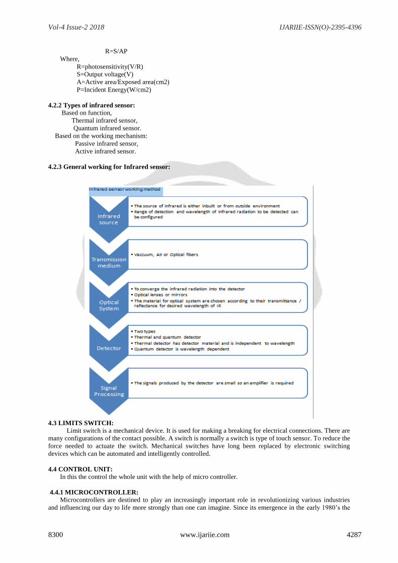
4.2.3 General working for Infrared sensor:
4.3 LIMITS SWITCH:
Limit switch is a mechanical device. It is used for making a breaking for electrical connections. There are
many configurations of the contact possible. A switch is normally a switch is type of touch sensor. To reduce the
force needed to actuate the switch. Mechanical switches have long been replaced by electronic switching
devices which can be automated and intelligently controlled.
4.4 CONTROL UNIT:
In this the control the whole unit with the help of micro controller.
4.4.1 MICROCONTROLLER:
Microcontrollers are destined to play an increasingly important role in revolutionizing various industries
and influencing our day to life more strongly than one can imagine. Since its emergence in the early 1980’s the
Vol-4 Issue-2 2018 IJARIIE-ISSN(O)-2395-4396
8300 www.ijariie.com 4288
microcontroller has been recognized as a general purpose building block for intelligent building system. It is
finding using diverse area, starting from simple children’s toys to highly complex space craft. Because of its
versatility and many advantages, the application domain has spread in all consequence, it has generate a great
deal of interest and enthusiasm among students, teachers and practicing engineers, creating an acute education
need for importing the knowledge of micro controller based system design and development. It identifies the
vital features responsible for their tremendous impact; the acute educational need create by them and provides a
glimpse of the major application area.
A microcontroller is complete microprosser system built on a signal Ic. Microcontrollers were developed to
meet a need for microprocessors to be put in to low cost products. Building a complete microprocessor
System on a single clip substantially reduces the cost of building simple products, which use the
microprocessors power to implement their function, because the microprocessor is a natural way to implements,
many products. This means the ideas of using a microprocessor for low cost products comes up often. But the
typical 8-bit microprocessor based system, such as one using a Z80 and 8085 is expensive. Both 8085 and Z80
system need some additional circuits to make a microprocessor system. Each parts carry costs of money. Even
though a product design may require only very simple system, the part needed to make this system has a low
cost product.
To solve this problem microprocessor system is implemented with a single clip microcontroller. This could
be called microcomputer, as all the major parts are in the IC. Most frequently they are called microcontroller
because they are used to perform control function.
A microcontroller contains full implementation of a standard MICROPROCESSOR, ROM, RAM, I/0,
CLOCK, TIMERS, and also SERIAL PORTS. Microcontroller also called “system on a chip” or “single chip
microprocessor system” or “computer on a chip”.
The microcontroller is a Computer-On-A-Chip, or, if you prefer, a single-chip computer. Micro suggests
that the device might be used to control objects, processes, or events. Another term to describe a microcontroller
and its support circuits are often built into, or embedded in, the devices they control.
Today microcontrollers are very commonly used in wide variety of intelligent products. For example, most
personal computers keyboards and implemented with a microcontroller. It replaces scanning, de bounce matrix
decoding, and serial transmission circuits. Many low cost products, such as toys, electric drills, microwave
ovens, VCR and a host of other consumer and industrial products are based on microcontrollers.
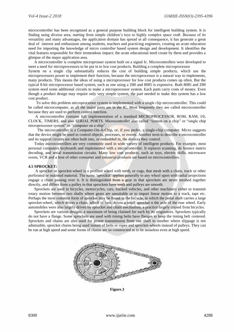
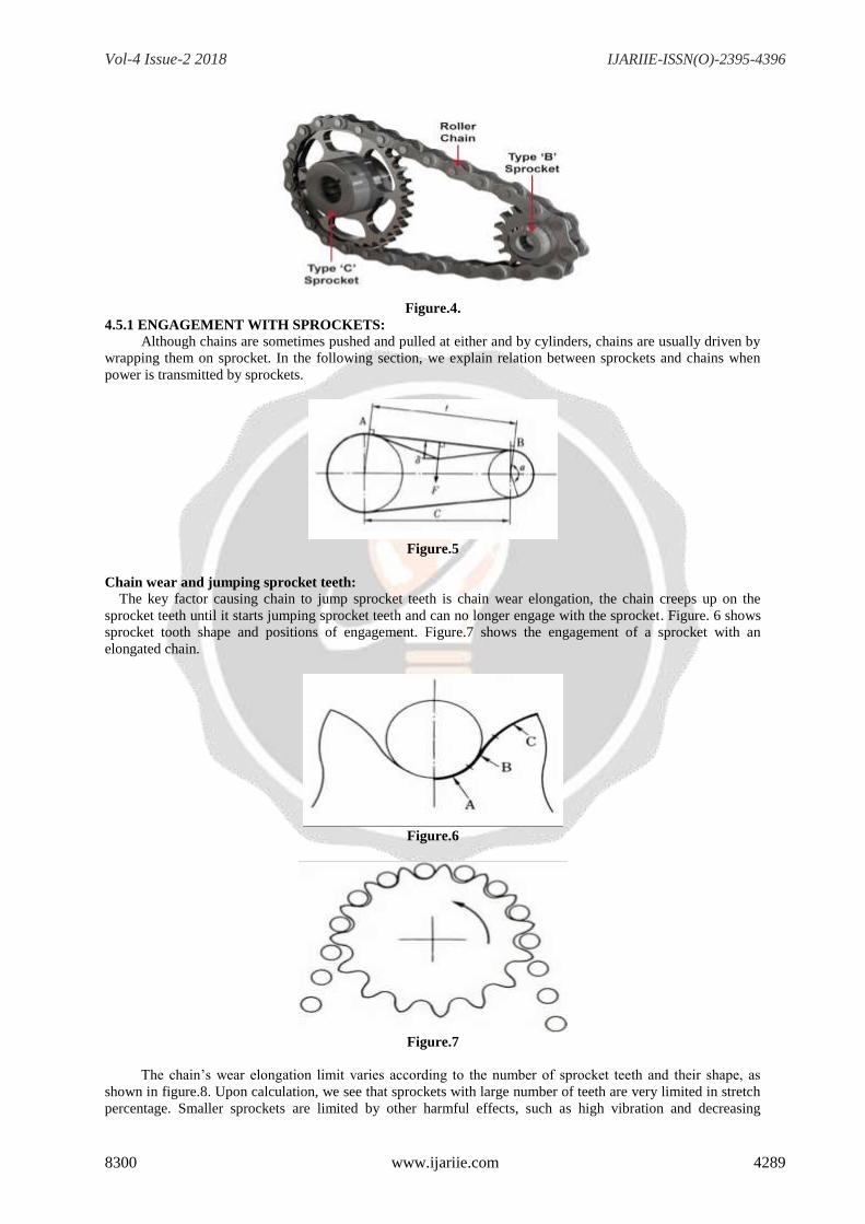
4.5 SPROCKET:
A sprocket or sprocket-wheel is a profiled wheel with teeth, or cogs, that mesh with a chain, track or other
perforated or indented material. The name ‘sprocket’ applies generally to any wheel upon with radial projections
engage a chain passing over it. It is distinguished from a gear in that sprockets are never meshed together
directly, and differs from a pulley in that sprockets have teeth and pulleys are smooth.
Sprockets are used in bicycles, motorcycles, cars, tracked vehicles, and other machinery either to transmit
rotary motion between two shafts where gears are unsuitable or to impart linear motion to a track, tape etc.
Perhaps the most common form of sprocket may be found in the bicycle, in which the pedal shaft carries a large
sprocket-wheel, which drives a chain, which in turn, drives a small sprocket n the axle of the rear wheel. Early
automobiles were also largely driven by sprocket and chain mechanism, a practice largely copied from bicycles.
Sprockets are various designs, a maximum of being claimed for each by its originators. Sprockets typically
do not have a flange. Some sprockets are used with timing belts have flanges to keep the timing belt centered.
Sprockets and chains are also used for power transmission from one shaft to another where slippage is not
admissible, sprocket chains being used instant of belts or ropes and sprocket-wheels instead of pulleys. They can
be run at high speed and some forms of chains are so constructed as to be noiseless even at high speed.
Figure.3
Vol-4 Issue-2 2018 IJARIIE-ISSN(O)-2395-4396
8300 www.ijariie.com 4289
Figure.4.
4.5.1 ENGAGEMENT WITH SPROCKETS:
Although chains are sometimes pushed and pulled at either and by cylinders, chains are usually driven by
wrapping them on sprocket. In the following section, we explain relation between sprockets and chains when
power is transmitted by sprockets.
Figure.5
Chain wear and jumping sprocket teeth:
The key factor causing chain to jump sprocket teeth is chain wear elongation, the chain creeps up on the
sprocket teeth until it starts jumping sprocket teeth and can no longer engage with the sprocket. Figure. 6 shows
sprocket tooth shape and positions of engagement. Figure.7 shows the engagement of a sprocket with an
elongated chain.
Figure.6
Figure.7
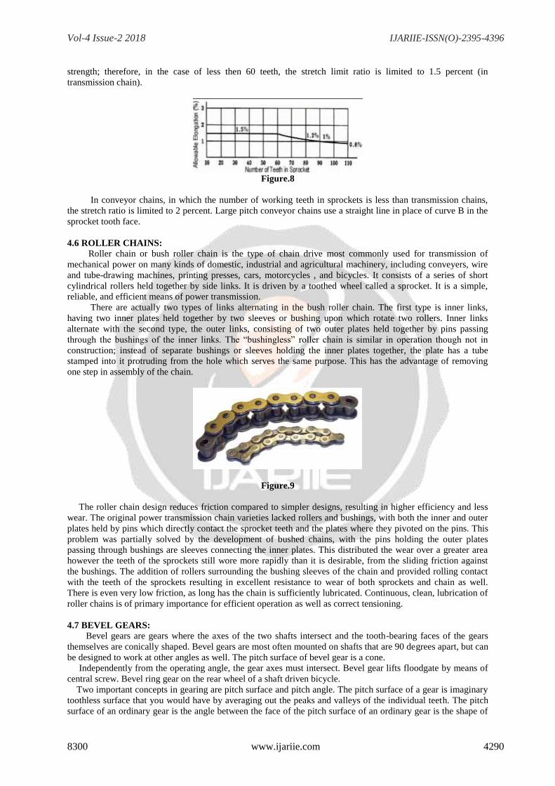
The chain’s wear elongation limit varies according to the number of sprocket teeth and their shape, as
shown in figure.8. Upon calculation, we see that sprockets with large number of teeth are very limited in stretch
percentage. Smaller sprockets are limited by other harmful effects, such as high vibration and decreasing
Vol-4 Issue-2 2018 IJARIIE-ISSN(O)-2395-4396
8300 www.ijariie.com 4290
strength; therefore, in the case of less then 60 teeth, the stretch limit ratio is limited to 1.5 percent (in
transmission chain).
Figure.8
In conveyor chains, in which the number of working teeth in sprockets is less than transmission chains,
the stretch ratio is limited to 2 percent. Large pitch conveyor chains use a straight line in place of curve B in the
sprocket tooth face.
4.6 ROLLER CHAINS:
Roller chain or bush roller chain is the type of chain drive most commonly used for transmission of
mechanical power on many kinds of domestic, industrial and agricultural machinery, including conveyers, wire
and tube-drawing machines, printing presses, cars, motorcycles , and bicycles. It consists of a series of short
cylindrical rollers held together by side links. It is driven by a toothed wheel called a sprocket. It is a simple,
reliable, and efficient means of power transmission.
There are actually two types of links alternating in the bush roller chain. The first type is inner links,
having two inner plates held together by two sleeves or bushing upon which rotate two rollers. Inner links
alternate with the second type, the outer links, consisting of two outer plates held together by pins passing
through the bushings of the inner links. The “bushingless” roller chain is similar in operation though not in
construction; instead of separate bushings or sleeves holding the inner plates together, the plate has a tube
stamped into it protruding from the hole which serves the same purpose. This has the advantage of removing
one step in assembly of the chain.
Figure.9
The roller chain design reduces friction compared to simpler designs, resulting in higher efficiency and less
wear. The original power transmission chain varieties lacked rollers and bushings, with both the inner and outer
plates held by pins which directly contact the sprocket teeth and the plates where they pivoted on the pins. This
problem was partially solved by the development of bushed chains, with the pins holding the outer plates
passing through bushings are sleeves connecting the inner plates. This distributed the wear over a greater area
however the teeth of the sprockets still wore more rapidly than it is desirable, from the sliding friction against
the bushings. The addition of rollers surrounding the bushing sleeves of the chain and provided rolling contact
with the teeth of the sprockets resulting in excellent resistance to wear of both sprockets and chain as well.
There is even very low friction, as long has the chain is sufficiently lubricated. Continuous, clean, lubrication of
roller chains is of primary importance for efficient operation as well as correct tensioning.
4.7 BEVEL GEARS:
Bevel gears are gears where the axes of the two shafts intersect and the tooth-bearing faces of the gears
themselves are conically shaped. Bevel gears are most often mounted on shafts that are 90 degrees apart, but can
be designed to work at other angles as well. The pitch surface of bevel gear is a cone.
Independently from the operating angle, the gear axes must intersect. Bevel gear lifts floodgate by means of
central screw. Bevel ring gear on the rear wheel of a shaft driven bicycle.
Two important concepts in gearing are pitch surface and pitch angle. The pitch surface of a gear is imaginary
toothless surface that you would have by averaging out the peaks and valleys of the individual teeth. The pitch
surface of an ordinary gear is the angle between the face of the pitch surface of an ordinary gear is the shape of
Vol-4 Issue-2 2018 IJARIIE-ISSN(O)-2395-4396
8300 www.ijariie.com 4291
the cylinder. The pitch angle of a gear is the angle between the face of the pitch surface and the axis. Bevel
gears that have pitch angles of grater then 90 degrees have teeth that point inward are called internal bevel gear.
Figure.10
The bevel gear has many diverse applications such as locomotives, marine applications, automobiles, printing
presses, cooling towers, steel plants, railway track inspection machines, etc.
Bevel gears are used in differential drives, which can transmit power to two axles spinning at different speeds,
such as those on a cornering automobile. Bevel gears are used as the main mechanism for a hand drill. As the
handle of the drill is turned in a vertical direction, the bevel gears change the rotation of the chuck to a
horizontal rotation. The bevel gears in a hand drill have the added advantage of increasing the speed of rotation
of the chuck and this makes it possible to drill a range of materials.
This gear makes it possible to change the operating angle. Differing of the number of teeth on each wheel
allows mechanical advantage to be changed. By increasing or decreasing the ratio of teeth between the drive and
driven wheels one may change the ratio of rotations between the two, meaning that the rotational drive and
torque of the second wheel can be changed in relation to the first, with speed increasing and torque decreasing,
or speed decreasing and torque increasing.
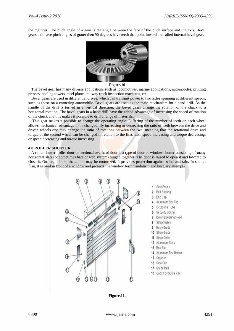
4.8 ROLLER SHUTTER:
A roller shutter, roller door or sectional overhead door is a type of door or window shutter consisting of many
horizontal slats (or sometimes bars or web system) hinged together. The door is raised to open it and lowered to
close it. On large doors, the action may be motorized. It provides protection against wind and rain. In shutter
firm, it is used in front of a window and protects the window form vandalism and burglary attempts.
Figure.11.
Vol-4 Issue-2 2018 IJARIIE-ISSN(O)-2395-4396
8300 www.ijariie.com 4292
4.9 TRANSFORMER:
A transformer is a static electrical device that transfers electrical energy between two or more circuits
through electromagnetic induction. A varying current in one coil of the transformer produces a varying magnetic
field, which in turn induces a varying electromotive force (emf) or "voltage" in a second coil. Power can be
transferred between the two coils through the magnetic field, without a metallic connection between the two
circuits. Faraday's law of induction discovered in 1831 described this effect. Transformers are used to increase
or decrease the alternating voltages in electric power applications. Since the invention of the first constant-
potential transformer i1885, transformers have become essential for the transmission, distribution, and
utilization of alternating current electrical energy. A wide range of transformer designs is encountered in
electronic and electric power applications. Transformers range in size from RF transformers less than a cubic
centimeter in volume to units interconnecting the power grid weighing hundreds of tons.
Figure.11
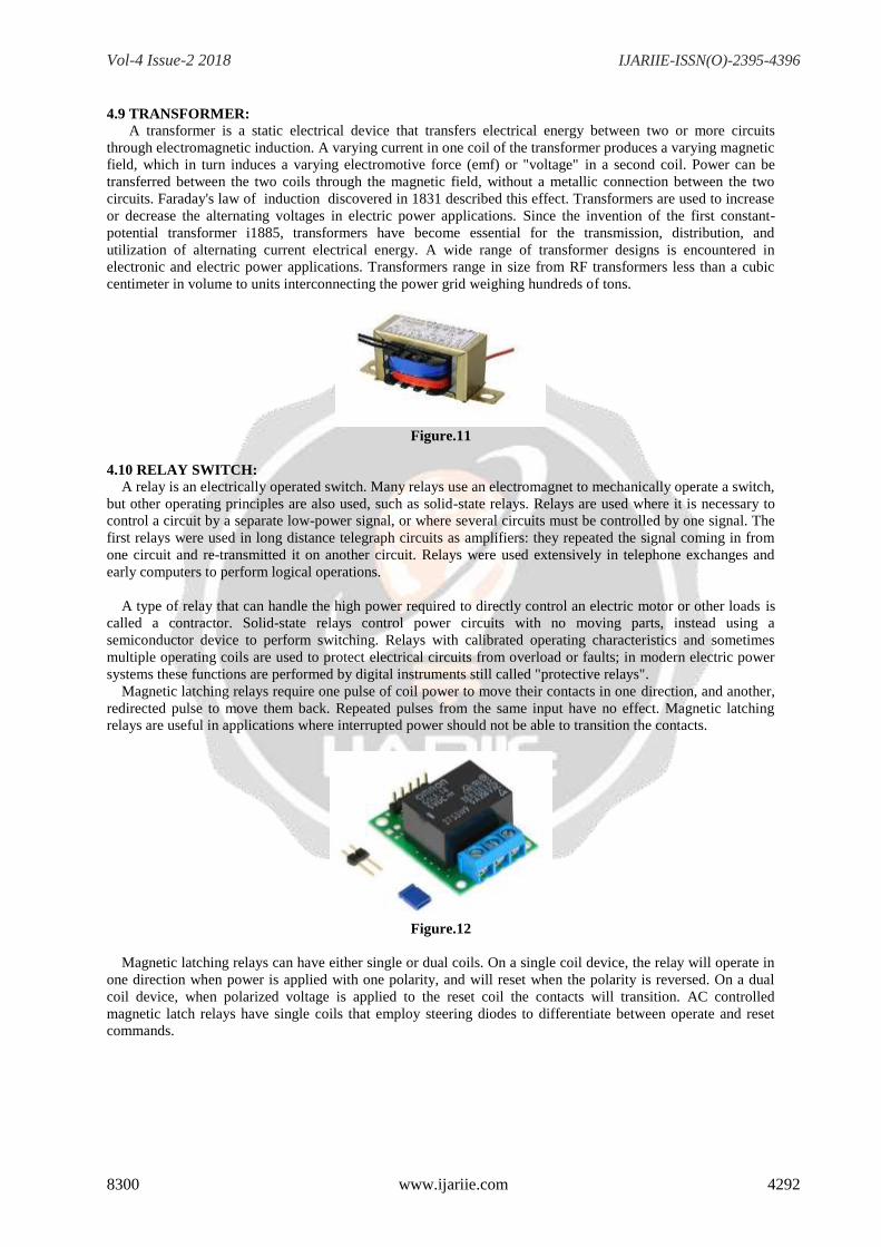
4.10 RELAY SWITCH:
A relay is an electrically operated switch. Many relays use an electromagnet to mechanically operate a switch,
but other operating principles are also used, such as solid-state relays. Relays are used where it is necessary to
control a circuit by a separate low-power signal, or where several circuits must be controlled by one signal. The
first relays were used in long distance telegraph circuits as amplifiers: they repeated the signal coming in from
one circuit and re-transmitted it on another circuit. Relays were used extensively in telephone exchanges and
early computers to perform logical operations.
A type of relay that can handle the high power required to directly control an electric motor or other loads is
called a contractor. Solid-state relays control power circuits with no moving parts, instead using a
semiconductor device to perform switching. Relays with calibrated operating characteristics and sometimes
multiple operating coils are used to protect electrical circuits from overload or faults; in modern electric power
systems these functions are performed by digital instruments still called "protective relays".
Magnetic latching relays require one pulse of coil power to move their contacts in one direction, and another,
redirected pulse to move them back. Repeated pulses from the same input have no effect. Magnetic latching
relays are useful in applications where interrupted power should not be able to transition the contacts.
Figure.12
Magnetic latching relays can have either single or dual coils. On a single coil device, the relay will operate in
one direction when power is applied with one polarity, and will reset when the polarity is reversed. On a dual
coil device, when polarized voltage is applied to the reset coil the contacts will transition. AC controlled
magnetic latch relays have single coils that employ steering diodes to differentiate between operate and reset
commands.
Vol-4 Issue-2 2018 IJARIIE-ISSN(O)-2395-4396
8300 www.ijariie.com 4293
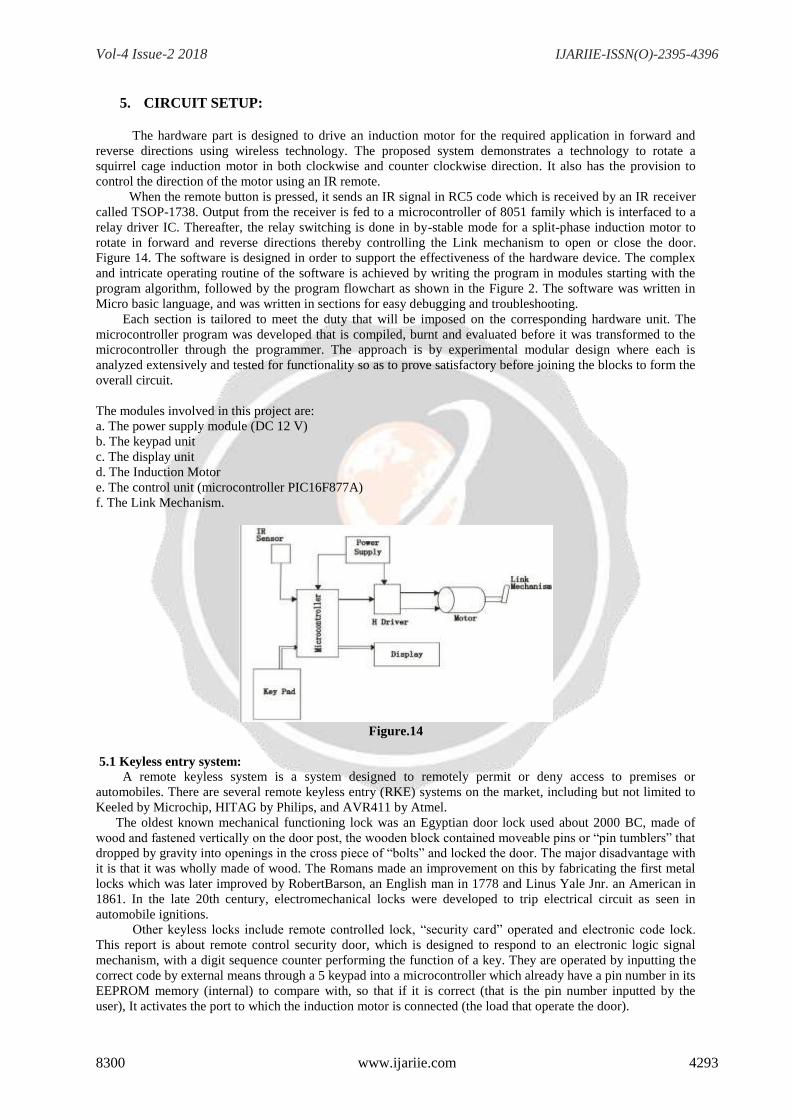
5. CIRCUIT SETUP:
The hardware part is designed to drive an induction motor for the required application in forward and
reverse directions using wireless technology. The proposed system demonstrates a technology to rotate a
squirrel cage induction motor in both clockwise and counter clockwise direction. It also has the provision to
control the direction of the motor using an IR remote.
When the remote button is pressed, it sends an IR signal in RC5 code which is received by an IR receiver
called TSOP-1738. Output from the receiver is fed to a microcontroller of 8051 family which is interfaced to a
relay driver IC. Thereafter, the relay switching is done in by-stable mode for a split-phase induction motor to
rotate in forward and reverse directions thereby controlling the Link mechanism to open or close the door.
Figure 14. The software is designed in order to support the effectiveness of the hardware device. The complex
and intricate operating routine of the software is achieved by writing the program in modules starting with the
program algorithm, followed by the program flowchart as shown in the Figure 2. The software was written in
Micro basic language, and was written in sections for easy debugging and troubleshooting.
Each section is tailored to meet the duty that will be imposed on the corresponding hardware unit. The
microcontroller program was developed that is compiled, burnt and evaluated before it was transformed to the
microcontroller through the programmer. The approach is by experimental modular design where each is
analyzed extensively and tested for functionality so as to prove satisfactory before joining the blocks to form the
overall circuit.
The modules involved in this project are:
a. The power supply module (DC 12 V)
b. The keypad unit
c. The display unit
d. The Induction Motor
e. The control unit (microcontroller PIC16F877A)
f. The Link Mechanism.
Figure.14
5.1 Keyless entry system:
A remote keyless system is a system designed to remotely permit or deny access to premises or
automobiles. There are several remote keyless entry (RKE) systems on the market, including but not limited to
Keeled by Microchip, HITAG by Philips, and AVR411 by Atmel.
The oldest known mechanical functioning lock was an Egyptian door lock used about 2000 BC, made of
wood and fastened vertically on the door post, the wooden block contained moveable pins or “pin tumblers” that
dropped by gravity into openings in the cross piece of “bolts” and locked the door. The major disadvantage with
it is that it was wholly made of wood. The Romans made an improvement on this by fabricating the first metal
locks which was later improved by RobertBarson, an English man in 1778 and Linus Yale Jnr. an American in
1861. In the late 20th century, electromechanical locks were developed to trip electrical circuit as seen in
automobile ignitions.
Other keyless locks include remote controlled lock, “security card” operated and electronic code lock.
This report is about remote control security door, which is designed to respond to an electronic logic signal
mechanism, with a digit sequence counter performing the function of a key. They are operated by inputting the
correct code by external means through a 5 keypad into a microcontroller which already have a pin number in its
EEPROM memory (internal) to compare with, so that if it is correct (that is the pin number inputted by the
user), It activates the port to which the induction motor is connected (the load that operate the door).
Vol-4 Issue-2 2018 IJARIIE-ISSN(O)-2395-4396
8300 www.ijariie.com 4294
5.2 The control unit:
The microcontroller PIC16F877A is the main control unit. PIC16F877A microcontroller was picked for
several reasons. Firstly, it is operated on a +5 V DC supply and draws very little current. Furthermore, it has a
very low power dissipation and high speed of operation and still maintains its data in case of power loss. Finally
it has a large storage memory. It processes and verifies the keypad inputs (Entered pin), and generate control
signals to power the induction motor attached to the Link mechanism. Thus, this is done by comparing the digits
with the right PIN number in the EEPROM memory (internal), if it is correct, it activates the port RD1which is
connected to the Induction motor (this represents the load), and also send an output text display on the LCD,
indicating “Enable mode.
5.3 The keypad unit:
The keypad is employed as an external interface to the system through, the output of the button pressed on
the keypad is displayed on the LCD, this help to makes correction if a mistake is made during the typing of the
codes. When the input pin is correct it causes the microcontroller to generate the control to drive the Induction
Motor either to open or close the door.
5.4 The display panel unit:
The display used is the 16 × 2 LCD liquid crystal display so as to give the user the opportunity of textual
display as compared to conventional ones which shows digits. 16 × 2 LCD uses a serial protocol having 8pins
with 4 pins used for communication with the microcontroller and the rest four pins used for other various
function such as Reset, Ground, Volt and add of 5 V to run the LCD.
5.2 SPECIFICATIONS:
AC induction motor 12V, one horse power AC induction motor to
connecting the crank.
Transformer 230V AC from a 12V DC supply to the circuit
board.
Microcontroller PIC16F877A is connecting to the main control
unit. Microcontroller picked for many reasons.
Relay switches SC5 Eco-S-DC 12V to controlling the forward
and reverse motion of the AC induction motor.
Infrared sensor To using of the ON and OFF the AC induction
motor to remote control usage.
Sprockets Size 12 is connecting on the AC induction motor
and Size 22 is connecting on the link rod.
Roller chain 2 meters’ roller chains are used to connecting the
AC induction motor and link rod sprockets.
IR remote
Infrared remote is controlling the AC induction
motor operating control for forward, reversed,
and OFF the motor.
5.3 INSTALLATION REQURIEMENTS:
5.3.1 Elecrically Supply:
Provide 230 +/- 10 VAC, 50 HZ, single phase electric supply with proper earthing. (Neutral-Earth voltage
less than 5 VAC)
Provide 230V, 50HZ, single phase electric supply is supplied into the transformer, and 12V single phase
electric supply passed into the circuit board. 12V single phase electrical supply passing into the another
transformer, and finally 230V single phase electric supply passing threw the AC induction motor.
5.3.2 Infrared Remote:
Infrared remote is controlling to the sensor circuit board and controlling the motor forward, reversed and
stop the AC induction motor system.
The infrared remote control is mostly used to ON and OFF the AC induction motor.
Vol-4 Issue-2 2018 IJARIIE-ISSN(O)-2395-4396
8300 www.ijariie.com 4295
6. RESULT AND DISCUSSION
6.1 RESULTS:
6.1.1 Testing and performance:
The following tests are carried out on the project:
a) Continuity Test
b) Insulation resistance test
c) Earth leakage test
d) Performances test
a) Continuity test: This test was carried out to ascertain whether there is no open circuit between the contact.
According to the 16th
edition of IEE regulation, the continuity test must be carried out to known whether there is
open circuit or not in the relay. The testing result display zero in the multimeter.
b) Insulation resistance: This is carried out to determine whether there is no breakdown of insulation in the
coil of the relay. The testing result display, infinity in the multimeter.
c) Earth leakage: This is to determine whether there is no linkage between the contacts of the relay to the
ground. The testing result display, zero in the multimeter.
d) Performance test: The project is “Remote Controlled security door System”. Its performance range of
operation and distance coverage of operation. If the battery is fully charged it can work for at least 20 HR, the
battery is 12 v, 7.2 A and secondly distance coverage is 9.4 m long, but 30 feet in meters’ conversion, the rate at
which the door opens and closes is 5 sec (seconds). After construction of the entire system, the hardware parts
including the Power supply, the 16 2 LCD, the keypad were tested on the bread board while the software
debugging was done using the micro basic crack simulator
6.1.2 Testing of the power supply unit:
The power supply circuit was connected on the breadboard with voltmeters connected across some points to
get the output voltages and current.
6.2 DISCUSSION:
It is economically wise to use Remote controlled security door using relay since most remote controlled door
uses card reader, this project will be of great importance because two relays were used for the supply and two
transistors that powered the relays instead of costly circuit.
7. CONCLUSION:
The security remote door is capable of delivering a +230 V AC, 50 HZ supply from an input voltage of 12 V
DC switching rate of the programmed circuit determines the rate of operation of the output AC signal delivered
to the load. The project involves an infra-red communication between an infra-red activated door and our serial
infrared control unit [SIRCU] device and communication between the SIRCU sensor and a PIC located within
the house and denies entry to a room or building.
8. REFERENCE:
(1). Ekejiuba CO,Folyon GB-”Remote Controlled Security Door”, “Journal of Electrical &Electronic Systems,
Volume5, Issue2,2016.
(2). Kushali Sindhia et.al-”Design Of Rolling Shutters for Low Cost Operations"," International Journal of
Engineering Research in Mechanical and Civil Engineering,Volume2,Issue3, March2017 .
(3). Vipin Khandar,Dr.A.V.Vanalkar-”Design Analysis for Gear Motor System Assembly to Automate the
Rolling Shutter Operation”,”International Journal for Scientific
Research&Development”,vol.4, Issue 06,2016.
(4). Zahid Pathan,Vipin Khangar-”Computer Aided Design and Finite Element Analysis of Rolling
Shutter”,”International Journal for Scientific Research & Development”, vol.3, Issue 03, 2013.
Vol-4 Issue-2 2018 IJARIIE-ISSN(O)-2395-4396
8300 www.ijariie.com 4296
5). T.Appa Rao,et al, ”Thyristor controlled power of induction motor by IR Remote”, ”imperial journal of
interdicciplinery research”-vol-3,Issue -4,2017.
(6). Ayodele Sunday oluwole ,et al, ”design of automatic gate control using infrared remote with password
protected features”, “international journal for research and Development in technology”-vol-5,issue-5,NOV
2014.
(7). Dokhe Anita Dattagaya,et al, “Gesture recognition based AC Motor speed control”, “International journal of
engineering science and research technology”-vol-4, issue-6.JUNE 2015.
(8). Truptis Bobade, et al, “Induction Motor speed control using android application", "international journal of
engineering research and general science”-vol-3,issue -2,part-2, MARCH-APRIL-2015.


![“CFD ANALYSIS HELICAL COIL HEAT EXCHANGER”ijariie.com/AdminUploadPdf/CFD_ANALYSIS_HELICAL_COIL_HEAT_E… · Shinde Digvijay D. et al. [3] studied the experimental investigation](https://img.pdfslide.us/doc/110x75/5fa1c8c0022f2e4c0b162c6a/aoecfd-analysis-helical-coil-heat-exchangera-shinde-digvijay-d-et-al-3-studied.jpg)