Embed Size (px)
Citation preview
Automatic Placement/Arrangement of Underneath Bone Structures for 3D Facial
Expressions and Animations
Alice J. Lin Marshall University, Huntington, WV 25755
Fuhua (Frank) Cheng University of Kentucky, Lexington, KY, 40506
Abstract
This paper presents a new method for automatically setting the bones in a facial/head model to speed up the rigging process of a human face. To accomplish this, vertices of the face/head are grouped. The average distance between pairs of vertices is used to place the head bones. To set the bones for a face with multi-density, the mean value of the vertices in a group is measured. The method works on any particular person’s face/head model quickly and effectively, and provides a powerful means for generating facial expressions and animations. The time saved with the method is significant. Although we focus on human faces in this work, the concepts presented here are flexible enough to be used on non-human characters as well. Keywords: Facial Animation, Facial Expressions, Facial Rigging.
1. Introduction
Recent years have seen an explosion in 3D computer generated animation. The entertainment industry has played a crucial role, pushing computer graphics technology to the limit. The number of the studios producing computer animated films is increasing every year, while digital characters are becoming commonplace in traditional films. Most of the top grossing films in the United States have scenes with some form of computer animation. Animation is an important ingredient in computer games as well. The computer gaming industry is one of the fastest growing industries in recent times. This high demand has resulted in a need for improving the efficiency of the computer animation processes. One of the processes is rigging. This is a complex and time-consuming procedure requiring both artistic and technical savvy, especially when dealing with the human face, which is the most expressive part of the body and communicating both language and emotion. Human beings have developed an acute sensitivity to facial expressions and artifacts in facial movement are immediately noticeable. Additionally, although humans all share the same underlying facial structure, the range of face types is immense. Current facial

animation techniques, for example, parameterized models, provide ready-made, configurable and animatable faces, but the numbers of characters, which can be represented, are limited by the number of conformal parameters. Morphing systems, on the other hand, can represent virtually any character, but they depend on facial expression libraries, which must be built for each character. Additionally, these popular morphing algorithms do not simulate the motions in the face correctly. A rig is a set of controls that allows an artist to manipulate a character [1]. Building a facial model rig is an essential element for animating CG characters in feature films and computer games. Due to their intuitive controls and art directable nature, facial rigs are particularly popular among artists for creating realistic looking facial animations. The process of rigging is tedious and requires many hours of manual work for an artist. The common skinning approach requires manually defining the location of the joints (bones) of the skeleton. Then the artist needs to specify which parts of the surface are attached to which joint(s). More sophisticated models based on simulation of the facial tissues and muscles also need human intervention to attach tissues to the skeleton and to tune complex muscle configuration. In this work, we intend to increase the productivity of professional artists and allow even inexperienced users to quickly generate animated models. We present a method for the automated placement of bones on human face models, allowing the artist to immediately concentrate on the animation phase, providing significant time savings for this arduous task. Our approach is to group the vertices on the surface of a model which is optimized to support the deformations of a human face. Our method works on a particular person’s face and it allows the artist to control the shape of the skin deformations quickly and effectively.
2. Related Work
Rigging is the process of taking a static, inanimate computer model and transforming it into a character that an animator can edit frame-by-frame to create motion [2]. The result is a rig that can be manipulated by a set of controls like a virtual puppet [3] or by motion capture data. Creating a character rig is a very complex, time-consuming and labor intensive task. Still, there is no defined standard methodology for rigging a face. Today, facial animation is done manually by skilled artists, who carefully place and manipulate the animation controls to create the desired motion. In production environments, facial rigging is commonly done by geometric deformations, blendshapes, or combination of the two [4]. Many methods have been devised for the geometric deformation of surfaces, including free-form deformation [5], shape interpolation [6], and wire deformation [7]. Such methods form the building blocks for rigging in modern animation programs. The work of Kry et al. [8] used simulated input deformations to produce hand deformations. Baran and Popovi´c [9] proposed skeleton-embedding rigging for cartoon character body animations. Kahler et al.
[10] fitted a complex anatomical model to partial 3D scan data. Orvalho et al. [11] introduced a general rigging method by transferring a generic facial rig to 3D input scans and hand-crafted models. Li et al. [12] introduced a method for generating facial blendshape rigs from a set of example poses of a CG character. Hahn et al. [13] presented a method for character animations which is based on a linearized formulation of rig-space dynamics that uses only rig parameters. Poirier and Paquette [14] presented a method to use topology graphs to automatically adapt complex deformation skeletons. Complex skeletons are defined as having full control on all limbs. Capell et al. [15] introduced forces as the building blocks of rigging for a bent arm and a chest flex. Rigging forces guide the shape of the character, but are combined with other forces during simulation. Miller et al. [16] presented a new rigging and skinning method which uses a database of partial rigs extracted from a set of source characters. Teichmann and Teller [17] proposed a spring-based method. Because of its simplicity and efficiency, despite its quality shortcomings, linear blend skinning, also known as skeleton subspace deformation, remains the most popular method used in practice. Most real-time skinning work, e.g. [8, 18], has focused on improving linear blend skinning by inferring the character articulation from multiple example meshes.
3. Automatic Placement of Bones on Face/Head
Bone-based rigs are most often employed for full-body animations due to their intuitive control for articulated motion. Currently, it requires manually setting bones to specify its internal skeletal structure. Since both the body and limbs have articulations, it is not hard to attach bones to the surface; one only needs to set the bones to the skeleton’s position. The human face has an underlying skeletal structure and one main skeletal articulatory component - the jaw. Because the face only has a single mesh, it is very hard to manually place bones on the surface of the face to control facial expressions and animate it. Until now, there is no automation to set the bones for each individual face. We design a system to provide the ability to set up the control rig of a character efficiently. The rigging is to provide intuitive controls that can be manipulated to alter facial expressions desired by the animators. Each control is linked with a group of vertices. Our novel method is to auto group the vertices on the face and places the bones in proper positions. The goal is that the vertices within a group have high similarity but are very dissimilar to vertices in other groups. Dissimilarities are assessed based on the attribute values describing the face/head and the distance measured.
3.1 Placing the Head Bones
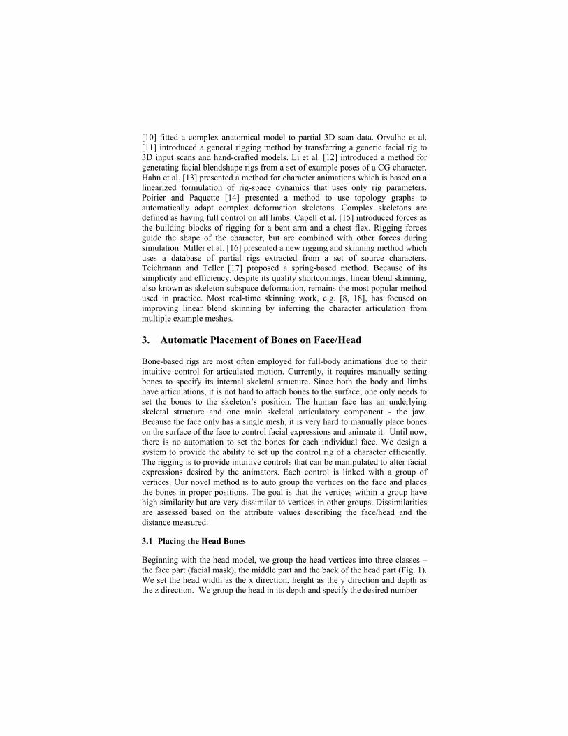
Beginning with the head model, we group the head vertices into three classes – the face part (facial mask), the middle part and the back of the head part (Fig. 1). We set the head width as the x direction, height as the y direction and depth as the z direction. We group the head in its depth and specify the desired number
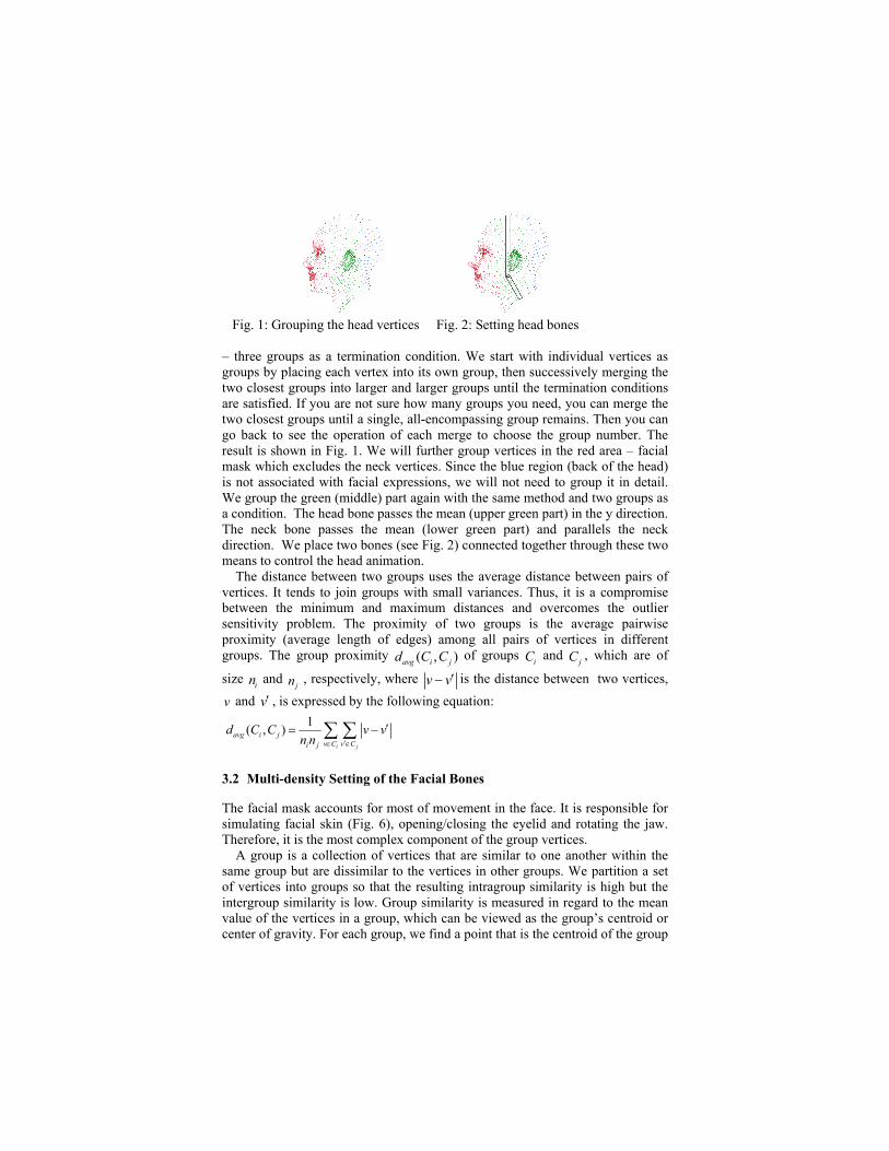
Fig. 1: Grouping the head vertices Fig. 2: Setting head bones – three groups as a termination condition. We start with individual vertices as groups by placing each vertex into its own group, then successively merging the two closest groups into larger and larger groups until the termination conditions are satisfied. If you are not sure how many groups you need, you can merge the two closest groups until a single, all-encompassing group remains. Then you can go back to see the operation of each merge to choose the group number. The result is shown in Fig. 1. We will further group vertices in the red area – facial mask which excludes the neck vertices. Since the blue region (back of the head) is not associated with facial expressions, we will not need to group it in detail. We group the green (middle) part again with the same method and two groups as a condition. The head bone passes the mean (upper green part) in the y direction. The neck bone passes the mean (lower green part) and parallels the neck direction. We place two bones (see Fig. 2) connected together through these two means to control the head animation. The distance between two groups uses the average distance between pairs of vertices. It tends to join groups with small variances. Thus, it is a compromise between the minimum and maximum distances and overcomes the outlier sensitivity problem. The proximity of two groups is the average pairwise proximity (average length of edges) among all pairs of vertices in different groups. The group proximity ( , )avg i jd C C of groups
iC and jC , which are of
size in and
jn , respectively, where v v is the distance between two vertices,
v and v , is expressed by the following equation:
3.2 Multi-density Setting of the Facial Bones
The facial mask accounts for most of movement in the face. It is responsible for simulating facial skin (Fig. 6), opening/closing the eyelid and rotating the jaw. Therefore, it is the most complex component of the group vertices. A group is a collection of vertices that are similar to one another within the same group but are dissimilar to the vertices in other groups. We partition a set of vertices into groups so that the resulting intragroup similarity is high but the intergroup similarity is low. Group similarity is measured in regard to the mean value of the vertices in a group, which can be viewed as the group’s centroid or center of gravity. For each group, we find a point that is the centroid of the group
1( , )
i j
avg i jv C v Ci j
d C C v vn n
2
1
,i
k
ii p C
E v
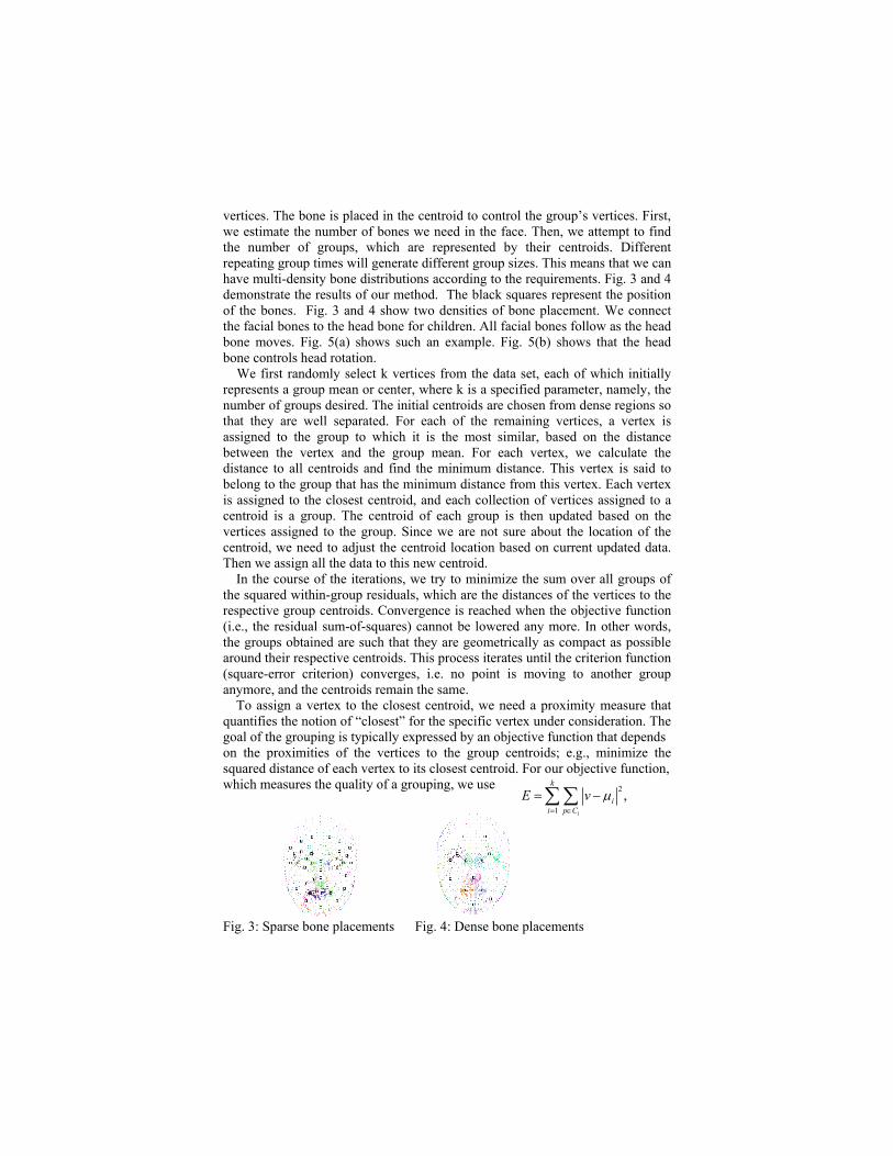
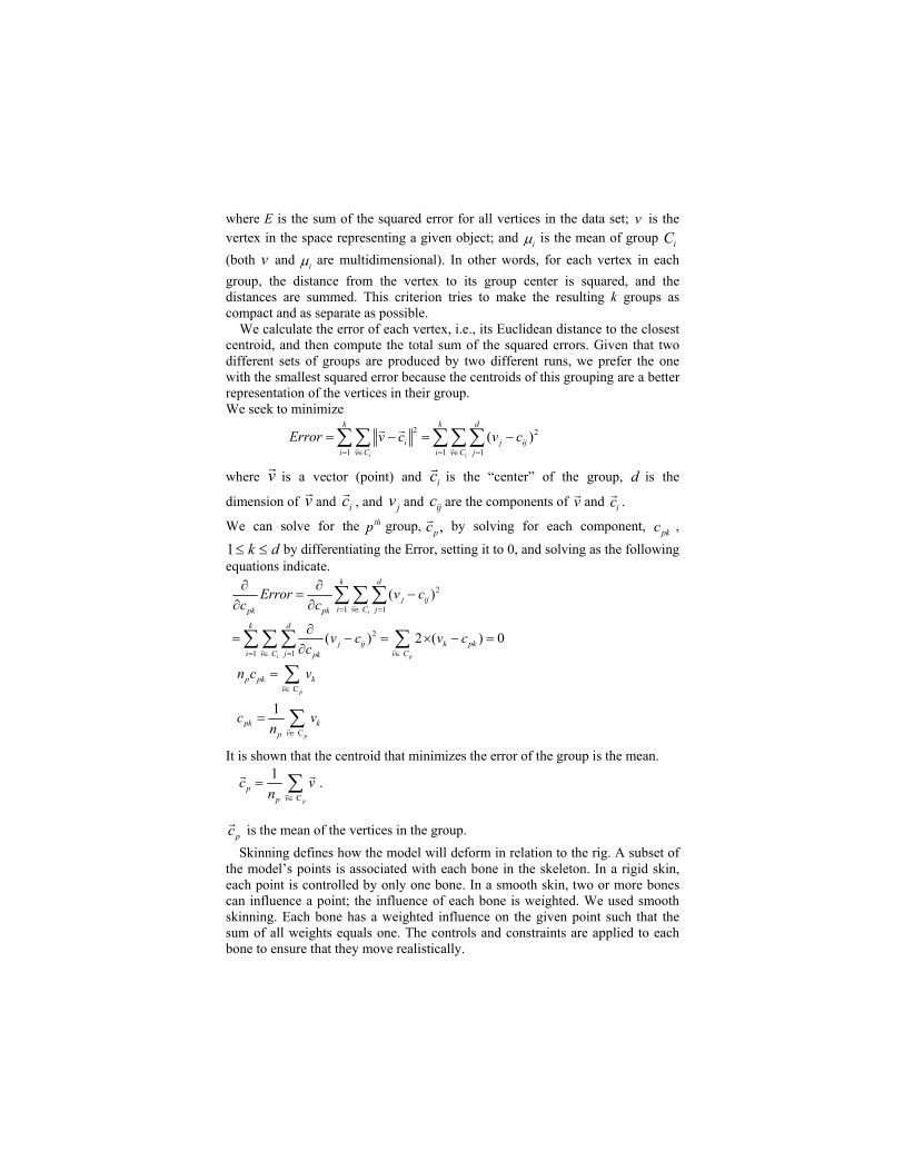
vertices. The bone is placed in the centroid to control the group’s vertices. First, we estimate the number of bones we need in the face. Then, we attempt to find the number of groups, which are represented by their centroids. Different repeating group times will generate different group sizes. This means that we can have multi-density bone distributions according to the requirements. Fig. 3 and 4 demonstrate the results of our method. The black squares represent the position of the bones. Fig. 3 and 4 show two densities of bone placement. We connect the facial bones to the head bone for children. All facial bones follow as the head bone moves. Fig. 5(a) shows such an example. Fig. 5(b) shows that the head bone controls head rotation. We first randomly select k vertices from the data set, each of which initially represents a group mean or center, where k is a specified parameter, namely, the number of groups desired. The initial centroids are chosen from dense regions so that they are well separated. For each of the remaining vertices, a vertex is assigned to the group to which it is the most similar, based on the distance between the vertex and the group mean. For each vertex, we calculate the distance to all centroids and find the minimum distance. This vertex is said to belong to the group that has the minimum distance from this vertex. Each vertex is assigned to the closest centroid, and each collection of vertices assigned to a centroid is a group. The centroid of each group is then updated based on the vertices assigned to the group. Since we are not sure about the location of the centroid, we need to adjust the centroid location based on current updated data. Then we assign all the data to this new centroid.
In the course of the iterations, we try to minimize the sum over all groups of the squared within-group residuals, which are the distances of the vertices to the respective group centroids. Convergence is reached when the objective function (i.e., the residual sum-of-squares) cannot be lowered any more. In other words, the groups obtained are such that they are geometrically as compact as possible around their respective centroids. This process iterates until the criterion function (square-error criterion) converges, i.e. no point is moving to another group anymore, and the centroids remain the same.
To assign a vertex to the closest centroid, we need a proximity measure that quantifies the notion of “closest” for the specific vertex under consideration. The goal of the grouping is typically expressed by an objective function that depends on the proximities of the vertices to the group centroids; e.g., minimize the squared distance of each vertex to its closest centroid. For our objective function, which measures the quality of a grouping, we use Fig. 3: Sparse bone placements Fig. 4: Dense bone placements
where E is the sum of the squared error for all vertices in the data set; v is the vertex in the space representing a given object; and
i is the mean of group iC
(both v and i are multidimensional). In other words, for each vertex in each
group, the distance from the vertex to its group center is squared, and the distances are summed. This criterion tries to make the resulting k groups as compact and as separate as possible. We calculate the error of each vertex, i.e., its Euclidean distance to the closest centroid, and then compute the total sum of the squared errors. Given that two different sets of groups are produced by two different runs, we prefer the one with the smallest squared error because the centroids of this grouping are a better representation of the vertices in their group. We seek to minimize
where v
is a vector (point) and ic
is the “center” of the group, d is the
dimension of v
and ic
, and jv and ijc are the components of v
and ic
.
We can solve for the thp group, ,pc
by solving for each component, pkc ,
1 k d by differentiating the Error, setting it to 0, and solving as the following equations indicate.
It is shown that the centroid that minimizes the error of the group is the mean.
pc
is the mean of the vertices in the group.
Skinning defines how the model will deform in relation to the rig. A subset of the model’s points is associated with each bone in the skeleton. In a rigid skin, each point is controlled by only one bone. In a smooth skin, two or more bones can influence a point; the influence of each bone is weighted. We used smooth skinning. Each bone has a weighted influence on the given point such that the sum of all weights equals one. The controls and constraints are applied to each bone to ensure that they move realistically.
2 2
1 1 1
( )i i
k k d
i j iji v C i v C j
Error v c v c
2
1 1
2
1 1
( )
( ) 2 ( ) 0
i
i p
k d
j iji v C jpk pk
k d
j ij k pki v C j v Cpk
Error v cc c
v c v cc
C
C
1p
p
p pk kv
pk kvp
n c v
c vn
C
1.
p
pvp
c vn
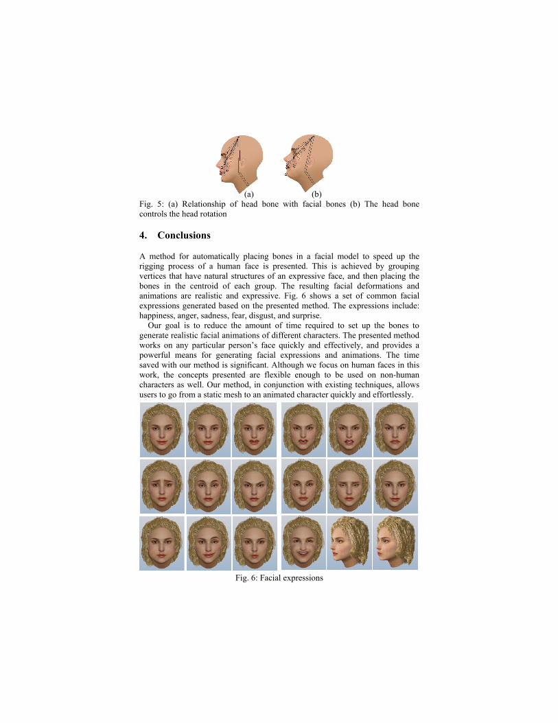
(a) (b) Fig. 5: (a) Relationship of head bone with facial bones (b) The head bone controls the head rotation
4. Conclusions
A method for automatically placing bones in a facial model to speed up the rigging process of a human face is presented. This is achieved by grouping vertices that have natural structures of an expressive face, and then placing the bones in the centroid of each group. The resulting facial deformations and animations are realistic and expressive. Fig. 6 shows a set of common facial expressions generated based on the presented method. The expressions include: happiness, anger, sadness, fear, disgust, and surprise. Our goal is to reduce the amount of time required to set up the bones to generate realistic facial animations of different characters. The presented method works on any particular person’s face quickly and effectively, and provides a powerful means for generating facial expressions and animations. The time saved with our method is significant. Although we focus on human faces in this work, the concepts presented are flexible enough to be used on non-human characters as well. Our method, in conjunction with existing techniques, allows users to go from a static mesh to an animated character quickly and effortlessly.
Fig. 6: Facial expressions

Acknowledgements
This work is supported by National Science Foundation of China (61020106001, 61170324), National Science Council of ROC (NSC-100-2811-E-007-021), and a joint grant of National Tsinghua University and Chang-Gung Memorial Hospital (101N2756E1).
References
[1] K. Richie, O. Alexander, and K. Biri, "The Art of Rigging," CG Toolkit, vol. 2, 2005. [2] R. Falk, D. Minter, C. Vernon, G. Aretos, L. Modesto, A. Lamorlette, et al., "Art-
directed Technology: Anatomy of a Shrek 2 Sequence," ACM SIGGRAPH’04 Course Notes, 2004.
[3] J. Schleifer, "Character Setup from Rig Mechanics to Skin Deformations: A Practical Approach," ACM SIGGRAPH’ 02 Course Notes, 2002.
[4] N. Magnenat-Thalmann, E. Primeau, and D.Thalmann, "Abstract Muscle Action Procedures for Human Face Animation," Visual Computer, vol. 3, pp. 290-297, 1988.
[5] R. Maccracken and K. I. Joy, "Free-Form Deformations with Lattices of Arbitrary Topology," Proceedings of SIGGRAPH 96, pp. 181-188, 1996.
[6] B. Allen, B. Curless, and Z. Popovic, "Articulated Body Deformation from Range Scan Data," Proceedings of SIGGRAPH 2002, vol. 21, pp. 612- 619, 2002.
[7] K. Singh and E. Fiume, "Wires: A Geometric Deformation Technique," In Proceedings of ACM SIGGRAPH 98, pp. 405-414, 1998.
[8] P. G. Kry, D. L. James, and D. K. Pai, "Eigenskin: Real Time Large Deformation Character Skinning in Hardware," In Proceedings of the 2002 ACM SIGGRAPH Symposium on Computer Animation, pp. 153-159, 2002.
[9] I. Baran and J. Popovic, "Automatic Rigging and Animation of 3d Characters," ACM Trans. Graph, vol. 26, p. 72, 2007.
[10]K. Kahler, J. Haber, and H.-P. Seidel, "Geometry-based Muscle Modeling for Facial Animation," In Proc. Graphics Interface, 2001.
[11] V. C. T. Orvalho, E. Zacur, and A. Susin, "Transferring the Rig and Animations from a Character to Different Face Models," Computer Graphics Forum, vol. 27, pp. 1997- 2012, 2008.
[12]H. Li, T. Weise, and M. Pauly, "Example-based facial rigging," ACM Transactions on Graphics, vol. Volume 29, p. 32, 2010.
[13]F. Hahn, B. Thomaszewski, S. Coros, R. W. Sumner, and M. Gross, "Efficient simulation of secondary motion in rig-space," SCA '13 Proceedings of the 12th ACM SIGGRAPH/Eurographics Symposium on Computer Animation pp. 165-171 2013.
[14]M. Poirier and E. Paquette, "Rig retargeting for 3D animation," Proceedings of Graphics Interface 2009 pp. 103-110, 2009
[15]S. Capell, M. Burkhart, B. Curless, T. Duchamp, and Z. Popović, "Physically based rigging for deformable characters," Graphical Models, vol. 69, pp. 71–87, 2007.
[16]C. Miller, O. Arikan, and D. Fussell, "Frankenrigs: building character rigs from multiple sources," Proceedings of the 2010 ACM SIGGRAPH symposium on Interactive 3D Graphics and Games, pp. 31-38 2010.
[17]M. Teichmann and S. Teller, "Assisted Articulation of Closed Polygonal Models," In Computer Animation and Simulation ’98, pp. 87-102, 1998.
[18]R. Wang, K. Pulli, and J. Popovic, "Real-Time Enveloping with Rotational Regression," ACM Transactions on Graphics, vol. 26, 2007.