Embed Size (px)
Citation preview

AUTOMATIC LOCK STITCH POCKET WELT SEWER (FOR FLAP ATTACHMENT)
AUTOMATIC LOCK STITCH SLANT POCKET WELT SEWER (fOR FLAP ATTACHMENT)
---"-------------____J BAS-61 0 L--1 _
BAS-611 INSTRUCT! ON MANUAL BAS-612
From the library of: Superior Sewing Machine & Supply LLC

CONTENTS
SPECIFICATIONS ............................................................................................................ 1
CONTROL PANEL ........................................................................................................... 2
INSTALLATION ................................................................................................................. 6
1. Setting-up the table ..................................................................................................... 6
2. Connecting the treadle ................................................................................................ 6
3. Fitting the spool stand ................................................................................................ 6
4. Fitting the material holder ........................................................................................... 6
5. Adjusting the air pressure ........................................................................................... 7
LUBRICATION ................................................................................................................... 7
<Standard lubrication> ...................................................................................................... 7
<Oiling> ................................................................................................................................ 8
CORRECT OPERATION ............................................................................................... 9
<Winding the bobbin thread > ........................................................................................... 9
<Threading the needle threads> ...................................................................................... 1 o <Threading the bobbin thread> ........................................................................................ 12
< Holding the needle threads and the bobbin threads> ................................................ 13
TREADLE AND START SWITCH ............................................................................... 14
<Treadle operation> ........................................................................................................... 14
<Setting the material > ........................................................................................................ 15
MARKtNG LIGHT ADJUSTMENT.............................................................................. 16
PROGRAMMING (Inputting a Standard Sewing Program) ........................................ 17
PROGRAMMING (Inputting a Flap Sewing Program) ................................................ 18
PROGRAMMING (Inputting a Cycle Sewing Program) .............................................. 20
<Checking the sewing cycle> ........................ -................................................................... 21
PROGRAMMING (Inputting an Angled Sewing Program) .......................................... 22
PROGRAM CHECKING ................................................................................................. 24
SEWING ............................................................................................................................... 25
<Setting the bobbin counter> ........................................................................................... 26
<Setting the piece counter> .............................................................................................. 26
< Resetting the piece counter> ......................................................................................... 26
<Adjusting the stitch tension> .......................................................................................... 27
CENTER KNIFE POSITION ADJUSTMENT ......................................................... 28
CORNER KNIFE POSITION ADJUSTMENT......................................................... 29
FLAP SENSOR SENSITIVITY ADJUSTMENT (BAS-611 ,BAS-612) .................. 30
<Adjusting the flap sensor sensitivity> ............................................................................ 30
<Sensitivity adjustments> ................................................................................................. 31
From the library of: Superior Sewing Machine & Supply LLC

TROUBLE ........................................................................................................................... . 32
<UPPER THREAD BREAKAGE Indicator Illuminating> ................................................ . 32 <BOBBIN EMPTY Indicator illuminating> ..................................................................... .. 32 <PROGRAMMING ERROR Indicator Illuminating> ...................................................... .. 33 <EMERGENCY STOP operation> ................................................................................... . 33 STACKER OPERATION DURING CYCLE SEWING ......................................... . 34
STANDARD ADJUSTMENTS (Machine Head) ........................................................ . 35
< Fitting a needle> .............................................................................................................. . 35 <Adjusting the upper and lower shaft timing> ............................................................. .. 35 <Adjusting the needle and rotary hook timing> ........................................................... .. 35
[Clearance between the needle and rotary hook point] ...................................... .. 35 [Clearance between the rotary hook and needle plate] ........................................ . 36 ! [Needle bar lift stroke and· needle bar height] ........................................................ . 36 [Clearance between the rotary hook and bobbin case opener] .......................... . 36
CARRIAGE FEED ADJUSTMENTS ......................................................................... . 37
<Parallelism adjustment of the needle and carriage feed> ......................................... . 37 <Carriage feed angle adjustment> .................................................................................. . 37 <Carriage feed height adjustment> ................................................................................ . 38 <Folding plate position adjustment> .............................................................................. . 38 <Binder position adjustment> .......................................................................................... .. 39
KNIFE REPLACEMENT ............................................................................................... .. 40
< Corner knife replacement> ........................................................................................... .. 40 < Needle thread knife replacement > ................................................................................ . 42 < Bobbin thread knife replacement> .............................................................................. .. 43 < Center knife replacement> ............................................................................................ .. 44 < Fixed knife replacement > .............................................................................................. .. 44
PARTS REPLACEMENT FOR SINGLE WELTING ............................................ . 45
<When changing from double welting to single welting> ............................................ . 45
MAIN CIRCUIT BOARD DIP SWITCHES .............................................................. . 46
WHEN CHANGING THE TREADLE OPERATION TO TIMER SWITCH CONTROL ....................................................................................... .. 48
PROGRAMING THE CARRIAGE FEED RESET TIMER .................................. . 50
MEMORY INITIALIZATION ........................................................................................ .. 51
ERROR CODES ............................................................................................................... . 52
TROUBLE-SHOOTING ................................................................................................. . 53
From the library of: Superior Sewing Machine & Supply LLC

SPECIFICATIONS
Model 151-610 I 151 -611 151-612
Machine head Automatic lock stitch pocket welt sewer Automatic lock stitch slant (for flap attachment) pocket welt sewer
(for flap attachment)
Sewing speed 2,500 sp (variable to 2,200 spm by DIP switch setting)
Flap sewing Not available I Available
Slant-welting Not available Available
Needle Mtx 190 # 16 (#16- #18)
Needle Gauge size Standard 10 mm (8, 12, 14, 18, 20 mm)
Seam length Gauge size 14 mm or less : 28 to 190 mm 36 to 190 mm (Pocket size) 16 mm or more : 36 to 190 mm
Flap sewing : 80 to 180 mm
Stitch length Lock stitch Standard at 2 mm (variable from 1.8 mm to 3.2 mm) Backstitch C Condensed : Standard at 1.0 mm (variable from 0.4 mm to 1.4 mm)
Back-tack : Standard at 2.0 mm (variable from 0.8 mm to 2.0 mm) (Variable by dip switch setting)
Power supply 3-phase 200V, 50/60Hz, 500W (Utilizing two of the 3-phase lines)
Dimensions 820 mm W x 1,300 mm D x 1,155 mm H
- 1-From the library of: Superior Sewing Machine & Supply LLC
CONTROL PANEL [1] BAS-610, -611
• ijiiU)tt.liiii
• iftf.J~!It·1M
• PROGRAM
• KHFE CIIAHGE & CYClE PGM.
EMERGENCY STOP
0 I MODE selector I Use to select the operating mode: AUTOMATIC, MANUAL, PROGRAM or KNIFE CHANGE 6 CYCLE PGM
8 I EMERGENCY STOP I I I BOBBIN COUNTER SET I push-button switch Press to effect an emergency stop or for setting the bobbin counter (see page 26).
8 I PROGRAMMING NUMBER - SELECT I push-button selector Press to change the program number. The number advances one each time the selector is pressed (1 --. 2--. 3--. 4--. 5) (see page 17).
0 I CYCLE PGM - SET I push-button switch Press to effect a cycle program (see page 20) .
0 I CYCLE PGM- CLEAR I push-button switch Press to clear a cycle program (see page 20) .
0 0 0 !SEAM LENGTH/BOBBIN COUNTER I push-button setter (numeric display) 0 x 1 oo (0, 1, F:flap) 0 x 1 0 (0 to 9, - ) 0 x 1 (0 to 9, =:J : right flap, c : left flap)
See page 18 for F- C and F- =:J displays. 0 I BOBBIN COUNTER -SET I push-button switch
Press to set the bobbin counter (see page 26). Also press this switch to correct the corner knife position (see page 29).
-2-From the library of: Superior Sewing Machine & Supply LLC

~I
~,
CD I BOBBIN COUNTER - SELECT I push-button selector Press to select the bobbin counter: No.1. No.2 or No.3 (see page 26). The· bobbin counter selection advances In the order 1 -. 2 -. 3.
CD I CORNER KNIFE I switch Set to ON to use the center knife. (The comer knife will not function when the CORNER KNIFE switch is set to ON with the CENTER KNIFE switch set to OFF.) The knife will rise during corner knife replacement even If the switch Is set to OFF.
C1 I CENTER KNIFE I switch Set to ON to use the center knife.
I) I STACKER I switch Set to ON to use the stacker.
e I CARRIAGE FEED I forward/backward switch Set to ADVANCE to move the carriage feed away from the operator. Use simultaneously with
G) I THREAD TRIMMER I switch Use In either MANUAL or AUTOMATIC mode when the carriage feed Is at the thread trimming position. Set to UPPER to lower the needle thread knife unit and then start to raise it In the neutral position to cut and hold the needle threads. Set to LOWER to release the bobbin threads from the bobbin thread knives and then cut and hold the bobbin threads at the neutral position. To display the number of work pieces, set to UPPER in the AUTOMATIC mode when the carriage feed Is at the home position.
8 I PROGRAMMING NUMBER I Indicator When the Indicator Is flashing, the program number can be changed by pressing the SELECT selector.
e I Program number I indicators The flashing Indicator shows the program to be run. In the AUTOMATIC MODE of cycle sewing, a flashing Indicator shows the sewing program to be run and a steady Indicator shows the program to be run after that. [Example 1] If the cycle sewing Is programmed as 1 -. 2 -. 3, the Indicator are:
1 2 3 4 5 Flashing Steady Steady Off Off
If the PROGRAMMING NUMBER - SELECT selector is pressed then or if program 2 has been run, the Indicators are:
1 2 3 4 5 Steady Flashing Steady Off Off
CD I SEAM LENGTH I/ '""'I 8...,..0:'"1018,......B"''T"INT'""':C....,OIIri'O ...... N ....... T ..... E ...... R ...... S~ETI;;r'll/ I CORNER KNIFE POSITIONAL CORRECTION I display When the SEAM LENGTH Indicator Illuminates, the display shows the seam length (unit: mm) or the flap selection. When the BOBBIN COUNTER SET Indicator Illuminates, the display shows the bobbin thread amount (unit: piece). The setting can be changed using setters • , 0 and e when the display Is flashing.
8 I BOBBIN cOUNTER I display The display shows the remainder on the bobbin counter with the Illuminating number Indicator No. 1, No.2 or No.3 (20).
fl I BOBBIN COUNTER NUMBER I Indicators The Indicator for the bobbin counter number selected by BOBBIN COUNTER - SELECT CO Illuminates.
fD I POWER I Indicator The indicator illuminates when the power switch Is set to ON.
-3-From the library of: Superior Sewing Machine & Supply LLC

CONTROL PANEL [2] BAS-612
r-·Elll!lll • PIIOGIWI
• IOIHOWU & ClO..E PGII.
STOP
©~T!RAI)
©i1()881jElFTY ~ ~ ~ ~ ©=-' rm rm rm
0 Pattern SELECT selector Select one slant pocket sewing pattern from the nine.
f)) Sewing pattern display and SEAM LENGTH SIDE, R/L indicators The sewing pattern program set with the selector is displayed on the LEDs.
Pattern 1 2 3 4 ;) 6 7 8 9
r :JJ r :JJ r ::n r ::n r :JJ r :JJ r :JJ r :JJ r :JJ
00 0 0 0 0 0 0 00 00 0 0 0 0 00 1(/)1 1(/)0 0(/)1 1(/)0 0(/)1 1(/)1 1(/)1 1(/)0 0(/)1
LED display I I I I I I I I I I I I I I I I I I I I I I I I I I I I I I I I I I I I I I I I I I I I I I I I I I I I I I lml Om I lmO lml lml lmO Om I lmO Om I L R l R L R L R L R L R f-+ L R H -m : rl h I ~~ h : : : l ri ~ l I I
Sewing I I I I I I I I I I I I I I I I I I I S =start
w· I I I I I I I I I I I I I I
I I I e I I e I I e I I e I I e I I e I I e I le E= end I I I I I I I I I I I I I I I I I I = length I I I I I I I I I I I I I I I I I
overall I lr I I 14 I I I I IY rl IY f-1l I ·- LL
g) S-side deviation amount display The LED display shows the deviation amount on the sewing-start side.
G) S-side deviation amount setter Set a deviation amount of 19 mm or less.
~ E-slde deviation amount display The LED display shows the deviation amount on the sewing-end side.
f) E-side deviation amount setter Set a deviation amount of 19 mm or less.
-4-From the library of: Superior Sewing Machine & Supply LLC

t:p;.t..:Ziiliii - -CENTER K.
BAS - 610
75•;/1~:/if------FLAP SENSOR
LEFT
Ill ~ Rl~@) ~T I l l @)
Ill ~ t:p;.t..:Zliliii ------- -CENTER K.
,...;;.;n:-r-;;----~ I l.l=;':!'=~
~ .. '1:::::::::::::~:------~ >.=-=-< iJ---~-,
BAS-61 1 BAS-612
fJ) , f)) I CENTER K. (knife) I positional correction counters
The S counter shows the start-side correction and the E counter shows the end-side correction.
0 : The center knife moves to the extreme outer position.
9 : The center knife moves to the extreme inner position.
BAS-611 and BAS-612 only
~: -_-~ _-~-~ ~~ ~ ~~ -_----~
-- ....._-
0 9 9 0
ClD I FLAP SENSOR - LEFT I indicator The indicator illuminates when the left flap sensor detects the material.
G) I FLAP SENSOR- RIGHT I indicator The indicator illuminates when the right flap sensor detects the material.
~ I FLAP SENSOR - LEFT I sensitivity control G) I FLAP SENSOR - RIGHT I sensitivity control
-5-
Seam length display
~SEAM ~B~N LENGTH COUNTER SET ... IIOIIBIN COUNTER
[ I 1-1 ,-, ( ) , ,_, ,_, M/ M
s?. ~E SET SEl£CT
DODD o~~~ N0.1 N0.2 N0.3
Flap display
~SEAM ~BOBBIN LENGTH COUNTER SET ... BOBBIN COUNTEJI
[:- - - J r u ,-, .-~ I_ M/ M f !_f l_t
s> ~E SET SELECT
DODD D~~~ N0.1 N0.2 N0.3
Bobbin counter-bobbin counter set display
~SEAM ~BOBBIN LENGTH COUNTER SET ... BOBBIN COUNTER
( l M/ M [ I C 1-1 l
I _I 1_1
S ;? _____ <:;: E SET SELECT
DODD D~~ ~ N0.1 N0.2 N0.3
Work piece counter display
~SEAM ~BOBBIN LENGTH COUNTER SET ... BOBBIN COUNTER
( '7 ~-: I : l M/M ( ,-: 'J ·: ) S ?: ___ ~ E SET SELECT ~ ~ ~
DOD D 101 N0.1 N0.2 N0.3
From the library of: Superior Sewing Machine & Supply LLC

INSTALLATION [1]
1. Setting-up the table
2. Connecting the treadle
3. Fitting the spool stand
• Fit spool stand 0 onto bracket 8 and secure with screw 0 .
-6-
• Set the machine table level. Loosen nut 0 and adjust the height by turning caster 8 .
• Lock the casters so that the table will not move. Lower lever 8 to lock caster 8 . T ~ move the table again, lower lever 8 .
• Remover three screws 0 and open side panel 8 . Plug 12P connector 8 for treadle 8 Into the connector port on the side panel.
4. Fitting the material holder
• Fit material holder 0 onto stud 8 and secure with screw 0 .
I
From the library of: Superior Sewing Machine & Supply LLC

' \
5. Adjusting the air pressure
LUBRICATION [1]
• Use Brother-specHied machine oil (High White #70). <Standard lubrication>
1. The standard operating air pressure Is 5 kg/cm2.
Adjust the air pressure by turning handle 0. 2. If water collects In bottle 8 close air cock •
and then turn drain cock 0 slowly in the arrowed direction to drain the water. * Be sure to close drain cock 0 after letting
the water out.
1. Filling the arm top oil tank 2. Adjusting the rotary hook lubrication
• Pour in the oil through oil cap 0 until its level reaches the upper line on oil gauge window8
• Replenish the oil when its level reaches the lower line.
-7-
~ More lubricant ~ Less lubricant
*To prevent extremely high oil consumption, be careful not to loosen lubrication adjustment screws • for the rotary hook too much. Slide the carriage feed while referring to page 10, remove the slide plate, and tilt the machine head.
From the library of: Superior Sewing Machine & Supply LLC

Lubrication [2]
<Oiling> Before initial use of the machine or after a long 'period of no use, be sure to add a drop or two of oil at the arrowed points.
m
-8-From the library of: Superior Sewing Machine & Supply LLC
CORRECT OPERATION [1]
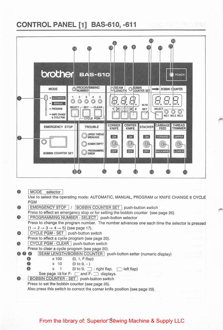
<Winding the bobbin thread>
1. Set power switch 0 to ON. 2. Place empty bobbin 8 onto bobbin winder shaft 0 3. Thread the thread from the spool stand as illustrated and wind the thread end around bobbin 8 for
five to six turns. 4. Move lever 8 In the arrowed direction.
The winder will start automatically and bobbin winder shaft 0 will revolve to wind the thread on the bobbin.
5. On completion of winding the maximum amount of thread, the lever returns automatically and bobbin winder shaft 0 will stop revolving.
6. To adjust the maximum thread amount for bobbin 8, loosen screw 8 and move lever 8 to the right or left.
7. Remove bobbin 8 from bobbin winder shaft 0 and cut the thread by winding It around thread holder 0. To wind another bobbin, take the thread end from thread holder 0 and wind it around the new one.
-9-From the library of: Superior Sewing Machine & Supply LLC
CORRECT OPERATION [2]
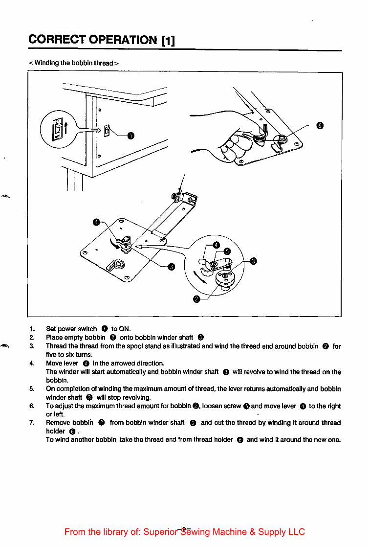
<Threading the needle thread> • Threading is easier when the carriage feed is advanced as this allows more space around the needle.
Before threading {To advance the carriage feed}
1. Set power switch 0 to ON (an alarm will sound once). The EMERGENCY STOP indicator will flash.
2. Press EMERGENCY STOP switch f) (an alarm will sound twice). Carriage feed 8 will move to the home position.
3. Set MODE selector 8 to MANUAL 4. Set CARRIAGE FEED switch e to FORWARD to advance the carriage feed.
* To fast-advance the carriage feed to the thread trimming position, set CARRIAGE FEED switch e to ADVANCE with THREAD TRIMMER switch 0 set to UPPER.
MODE
• PROGRAM
• KNIFE CHANGE ICYCLEPGM.
EMERGENCY STOP
ol / II
BOBBIN COUNTER SET
CARRIAGE THREAD FEED TRIMMER
-10-From the library of: Superior Sewing Machine & Supply LLC
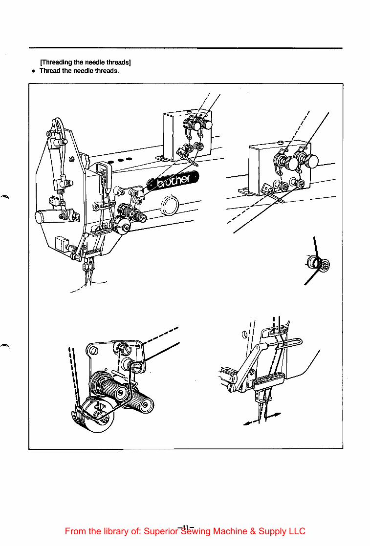
[Threading the needle threads] • Thread the needle threads.
-11-From the library of: Superior Sewing Machine & Supply LLC
CORRECT OPERATION [3]
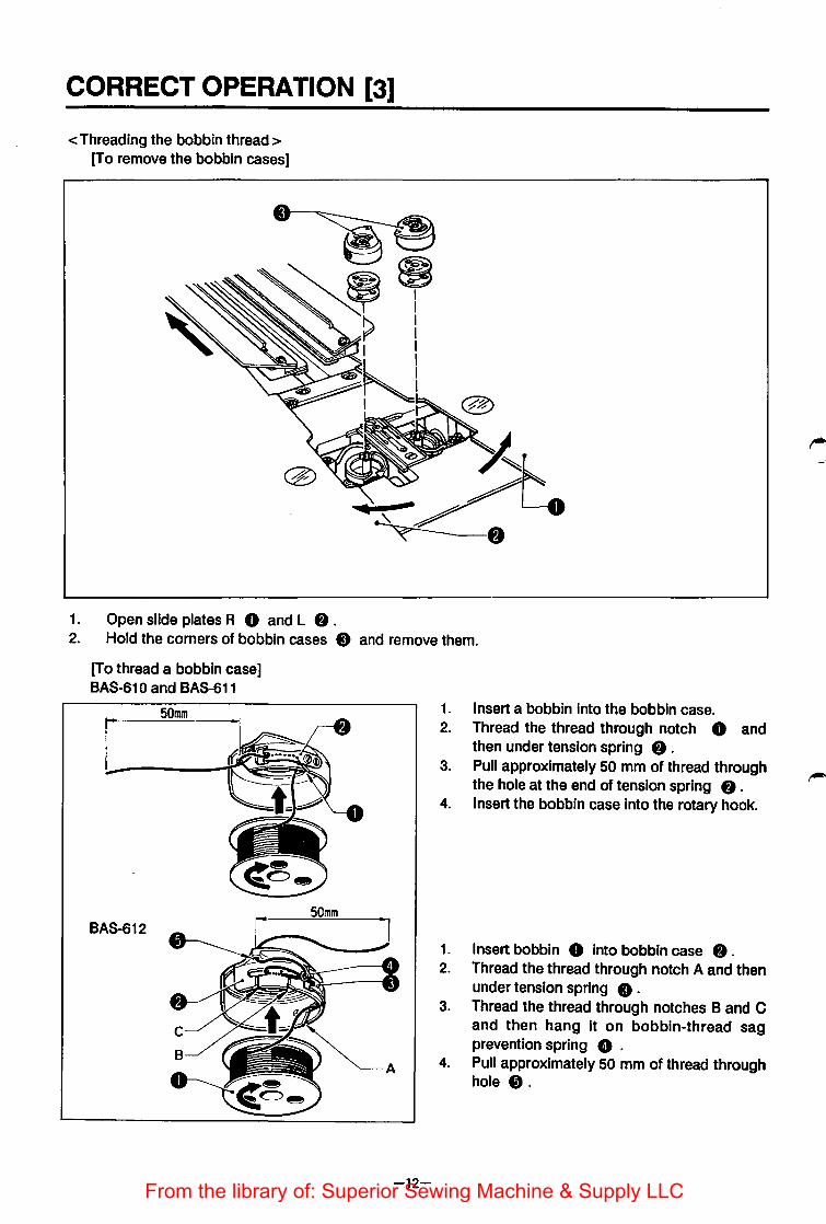
<Threading the bobbin thread> [To remove the bobbin cases]
1. Open slide plates A 0 and L 8 . 2. Hold the corners of bobbin cases 8 and remove them.
[To thread a bobbin case] BAS-610 and BAS-611
50mm
BAS-612
-12-
1. Insert a bobbin into the bobbin case. 2. Thread the thread through notch 0 and
then under tension spring 8 . 3. Pull approximately 50 mm of thread through
the hole at the end of tension spring 8 . 4. Insert the bobbin case Into the rotary hook.
1. Insert bobbin 0 into bobbin case 8 . 2. Thread the thread through notch A and then
under tension spring 0 . 3. Thread the thread through notches B and C
and then hang it on bobbin-thread sag prevention spring 8 .
4. Pull approximately 50 mm of thread through hole t).
From the library of: Superior Sewing Machine & Supply LLC
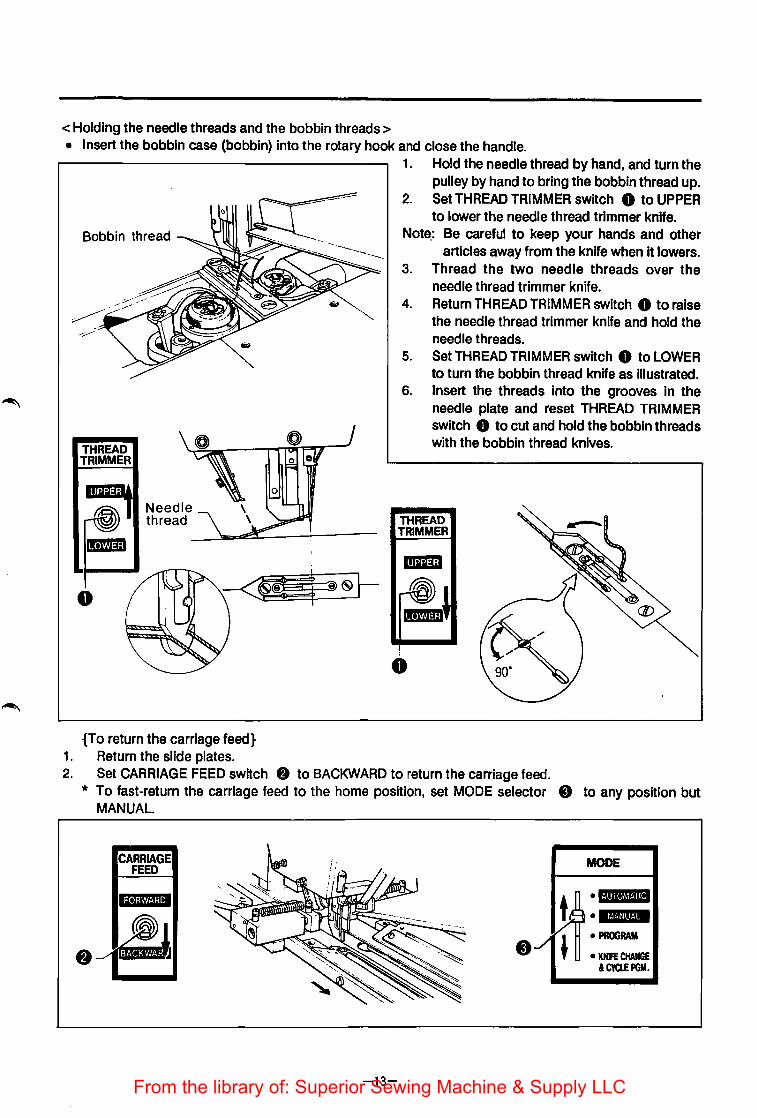
<Holding the needle threads and the bobbin threads> • Insert the bobbin case (bobbin) into the rotary hook and close the handle.
1. Hold the needle thread by hand, and turn the pulley by hand to bring the bobbin thread up.
2. Set THREAD TRIMMER switch 0 to UPPER to lower the needle thread trimmer knife.
Bobbin thread Note.: Be careful to keep your hands and other
THREAD TRIMMER
0
Needle thread
{To return the carriage feed} 1. Return the slide plates.
articles away from the knife when it lowers. 3. Thread the two needle threads over the
needle thread trimmer knife. 4. Return THREAD TRIMMER switch 0 to raise
the needle thread trimmer knife and hold the needle threads.
5. Set THREAD TRIMMER switch 0 to LOWER to turn the bobbin thread knife as illustrated.
6. Insert the threads into the grooves In the needle plate and reset THREAD TRIMMER switch 8 to cut and hold the bobbin threads with the bobbin thread knives.
THREAD TRIMMER
I
0
2. Set CARRIAGE FEED switch 8 to BACKWARD to return the carriage feed. * To fast-return the carriage feed to the home position, set MODE selector 8 to any position but
MANUAL.
CARRIAGE FEED
-13-
.../
MODE
~ •U•Nil • lt'll·!lll!·!·
' • PROGRAM • KNIFE CHANGE
&CYCL!PGM.
From the library of: Superior Sewing Machine & Supply LLC

TREADLE AND START SWITCH
• When running a flap program, the machine will not operate on pressing the start switch unless the flap presser lowers.
• For standard sewing, the machine will operate on pressing the start switch after the folding plate has operated.
• Set the MODE selector·either to AUTOMATIC or to MANUAL. <Treadle operation> 1. Press treadle 0 backwards to raise padding cloth presser foot springs R 8 and L 8 . 2. Release treadle 0 to lower padding cloth presser foot springs R 8 and L 8 . 3. Press treadle 0 forward to position 0 to lower carriage feed arm L 8 . 4. Press treadle 0 forward to position 8 to lower carriage feed arm R e . 5. Press treadle 0 forward to position 8 to lower binder 8 and operate the folding plate.
* The folding plate will start to operate 0.25 to 0.35 seconds after binder 8 lowers. 6. Press treadle 0 forward to position 8 to lower flap presser L 0 . 7. Press treadle 0 forward to position e to lower flap presser R 0 . 8. Press START switch 8 to operate the carriage feed.
* If the MODE selector is set to MANUAL, the carriage feed will operate without actual sewing. * The sequence of carriage feed and flap presser operations (steps 3, 4, 6 and 7 above) can be changed
by dip switch setting (see page 46).
C BA S-610
I 8 A s -611 • 612 I
-14-
fr '
.. It .......
From the library of: Superior Sewing Machine & Supply LLC

<Setting the material > • When running a flap program, the machine will not operate on pressing the start switch unless the flap
presser lowers. • For standard sewing, the machine will operate on pressing the start switch after the folding plate has
operated. 1. Press treadle 0 backward to raise padding cloth presser foot springs R f) and L 8 . 2. Position the padding. 3. Release treadle 0 to lower padding cloth presser foot springs R f) and L 8 and secure the
padding. * If the material is lined with padding, steps 0 to 8 above may be skipped.
4. Position the bodice. 5. Press treadle 0 forward to position 0 to lower carriage feed arm L 8 . 6. Press treadle 0 forward to position f) to lower carriage feed arm R 8 . 7. Position the welting material. 8. Press treadle 0 forward to position 8 to lower binder 0 and operate the folding plate.
(The welting material will be folded when lowered binder 0 holds the material.) * The folding plate will start to operate 0.25 to 0.35 seconds after binder 0 lowers.
9. Select either right flap sewing or left. 1 o. Press treadle 0 forward to position 8 to lower flap presser L 8 . 11. Press treadle 0 forward to position 8 to lower flap presser R 0 . 12. This completes the material setting.
1. Padding presser 2. Bodice
3. Welting material 4. Flap
~lngplate
-15-From the library of: Superior Sewing Machine & Supply LLC
MARKING LIGHT ADJUSTMENT
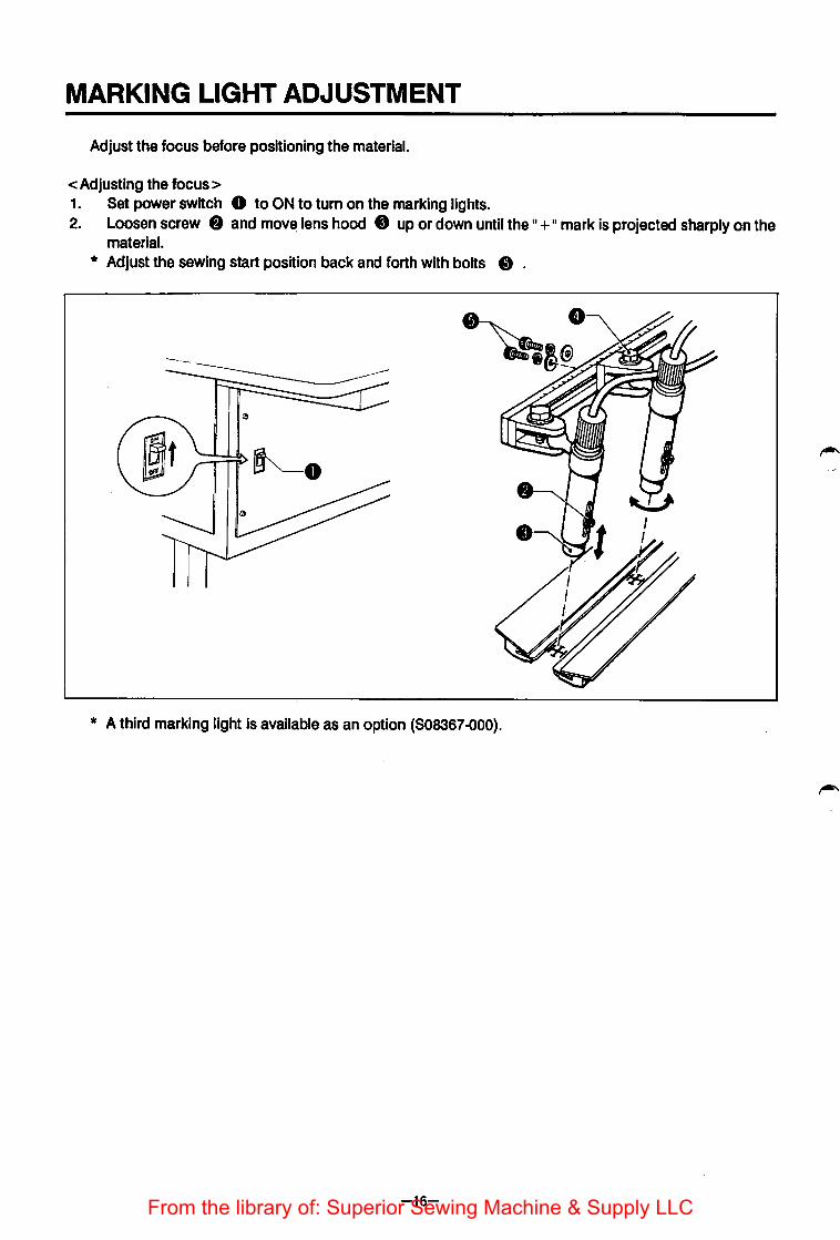
Adjust the focus before positioning the material.
<Adjusting the focus> 1. Set power switch 0 to ON to turn on the marking lights. 2. Loosen screw 8 and mov~ lens hood 0 up or down until the II+ II mark is projected sharply on the
material. * Adjust the sewing start position back and forth with bolts 8 .
* A third marking light Is available as an option (808367 -000).
-16-From the library of: Superior Sewing Machine & Supply LLC
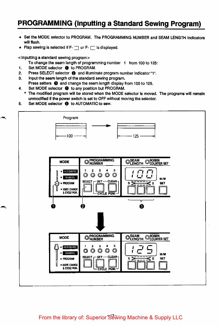
PROGRAMMING (Inputting a Standard Sewing Program)
• Set the MODE selector to PROGRAM. The PROGRAMMING NUMBER and SEAM LENGTH indicators will flash.
• Flap sewing is selected if F- =::J or F- C is displayed.
<Inputting a standard sewing program> To change the seam length of programming number 1 from 100 to 125:
1. Set MODE selector 0 to PROGRAM. 2. Press SELECT selector 8 and illuminate program number indicator 11111
•
3. Input the seam length of the standard sewing program. Press setters 8 and change the seam length display from 1 00 to 125.
4. Set MODE selector 0 to any position but PROGRAM. * The modified program will be stored when the MODE selector Is moved. The programs will remain
unmodified if the power switch is set to OFF without moving the selector. 5. Set MODE selector 0 to AUTOMATIC to sew.
Program .. I.,..._.._. 125~-1
MODE @PROGRAMMING .NUMBER
@SEAM (Q)BOBBIN LENGTH COUNTER SET
•IJIII•ItU!III 1 2 3 4 5 ,-, ,-, I ·•M.mw• ©@@©© , ,_, ,_,
M/M
rw·~ SELECT [EfDJ S >-_ ___ ~ E SET
• KHIFE CHANGE DOD D &CYCLE PGM. CYCLE PGM.
y
0
I MODE @PROGRAMMING
NUMBER @SEAM (Q)BOBBIN
LENGTH COUNTER SET 1. flllloVflil 1 2 3 4 5 I -, ,-@©@©@ , c =' • lt~!·!lll!·!· M/M
• PROGRAM DUC1JOJ S >-----~ E SET
• KNIFE CHANGE DOD D &CYCLEPGM.
-17-From the library of: Superior Sewing Machine & Supply LLC

PROGRAMMING {Inputting a Flap Sewing Program)
• Flap sewing programming is not available for BAS-61 0 machines. • Set the MODE selector to PROGRAM. The PROGRAMMING NUMBER and SEAM LENGTH Indicators
will flash. • Flap sewing Is selected IfF- =:J or F-C Is displayed.
F- =:J Indicates right flap sewing and F- C indicates left flap sewing. • Correct the sewing start position (correction data).
<Inputting a flap sewing program> To change programming number 2 to right flap sewing and modify the sewing start position correction data.
1. Set MODE selector 0 to PROGRAM. 2. Press SELECT selector 8 and Illuminate program number Indicator "211
•
3. Select either right flap sewing or left. Press setter (1 OO's place) 8 to show F on the SEAM LENGTH display. Press setter (1 's place) 8 to show =:J on the display.
4. Set the flap (see page 15 for setting a flap). 5. Press start switch 8 . f"
0
MODE
• i·i1U.!6foili
• 16fji!IMM
• PROGRAM
• KmOWEE & CYa.E PGif.
_fa.h'PROGRAMMiNG ~~UMBER
-18-
•
I I 1-1 ,-, -, '-'· ,_, 0~22
From the library of: Superior Sewing Machine & Supply LLC

6. The carriage feed advances 40 mm after the fl_ap sensor detects the flap edge. The BOBBIN COUNTER DISPLAY shows 1140.0 .. as the distance of travel after detecting the material edge.
7. Operate CARRIAGE FEED FORWARD/BACKWARD switch 8 to move the carriage feed so that the flap edge is at the sewing start needle position. The carriage feed can be moved in 0.2 mm steps.
8. Press BOBBIN COUNTER - SET switch 0 after adjusting the sewing start position. The carriage feed will return to the home position and the correction data shown on the BOBBIN COUNTER display will be stored. If EMERGENCY STOP switch 0 is pressed without pressing BOBBIN COUNTER - SET switch 8 , the carriage feed will return to the home position but the correction data will remain unmodified.
9. Set MODE switch 0 to any position but PROGRAM to store the program. * The modified program will be stored if MODE selector 0 is moved to any position but PROGRAM.
The seam length will remain unchanged if the power switch is set to OFF without this operation. * If the only change to be made is right or left flap selection, steps 4 to 8 can be skipped.
EMERGENCY STOP
0 / I BOBBIN COUNTER SET
c•
CARRIAGE FEED ~
I
l--40mm 1-------- )
~-----------------) I I
~·._. I
-19-From the library of: Superior Sewing Machine & Supply LLC

PROGRAMMING {Inputting a Cycle Sewing Program)
• CYCLE PGM. allows a maximum of any six combinations from program numbers 1 to 5 . • See the preceding pages to set standard or flap sewing programs for program numbers 1 to 5 .
<Inputting a cycle sewing program> To set a 1 __. 2-+ 1 -+ 3 sewing cycle
1. Set MODE selector 0 to KNIFE CHANGE & CYCLE PGM. 2. Press CYCLE PGM. CLEAR switch 8. 3. Press SELECT selector 0 to Illuminate program number indicator 11111
•
4. Press CYCLE PGM. - SET switch 8 to store program number 1 . 5. Press SELECT selector 0 to Illuminate program number indicator 11211
•
6. Press CYCLE PGM. - SET switch 8 to store program number 2 . 7. Press SELECT selector 0 to illuminate program number Indicator 11111
•
8. Press CYCLE PGM. - SET switch 8 to store program number 1 . 9. Press SELECT selector 0 to illuminate program number indicator 11311
•
10. Press CYCLE PGM. - SET switch 8 to store program number 3 . 11. Move MODE selector to any position but KNIFE CHANGE & CYCLE PGM.
o If a stacker operation is not programmed, it will be automatically programmed after the last program ;-. number (11311 above).
o See page 34 to operate the stacker Independently. * The modified cycle sewing sequence will be stored when MODE selector 0 is moved. The cycle
sewing sequence will remain unmodified if the power switch is set to OFF without moving the selector. * If a mistake is made during inputting, press CYCLE PGM. CLEAR SWITCH 8 and Input the program
again from the beginning.
-20-From the library of: Superior Sewing Machine & Supply LLC

MODE -~ROGRAMMING • UMBER
@SEAM @BOBBIN LENGTH 0 COUNTER SET ... BOBBIN COUNTER
·1·!111•1~1!·111 1 2 3 4 5 (- - Jl [- -) @@@@@ - -• MWf.!fiit·!M • PROGRAM
~~J S ~----~ E SET SELECT© © © 9 • KllfE CHAIU ODD D II II N0.1 N0.2 N0.3 &CYa.EPGM.
I 0
©Program number
1 2 3 4 5 Repetitive cycle sewing ·<~)~©©
1 -+ 2 -+.1 -+ 3 t
1 2 3 4 5
~·-©(Q) Sewing program sequence 1 2 3 4 5
••• ©(Q) 1 2 3 4 5
C)8.©©
<Checking the sewing cycle> 1. Set MODE selector 0 to KNIFE CHANGE & CYCLE PGM.
The sewing program sequence is shown on the SEAM LENGTH and BOBBIN COUNTER displays .
MODE • ROGRAMMING UMBER
@SEAM (Q)BOBBIN ... 0 NTER LENGTH COUNTER SET B BBIN COU
•l·!lilt~l·lill 1 2 3 4 5
( I -, ! Jl -,
©©©©© tC -;- -• •M.UIIt·'• --, • PROGRAM O[EfCLEA~
s :? ____ s e SET SELECT ~ ~ • KNIFE CHANGE ODD D D ©>©©
N0.1 N0.2 N0.3 &CYa.EPGM. CYCLE PGN
0 *The·.· after n3•Jndlcates stacker operation.
-21-From the library of: Superior Sewing Machine & Supply LLC
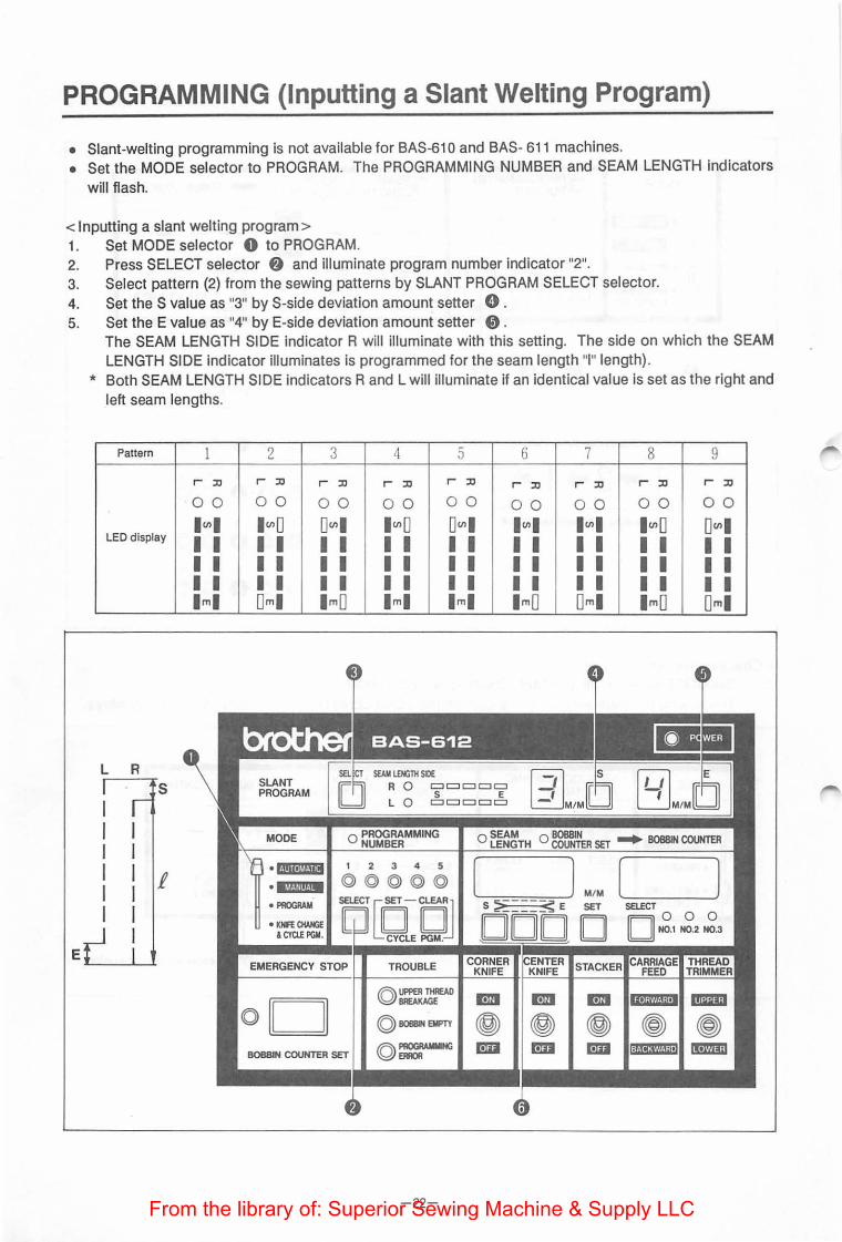
PROGRAMMING (Inputting a Slant Welting Program)
• Slant-welting programming is not available for BAS-610 and BAS- 611 machines. • Set the MODE selector to PROGRAM. The PROGRAMMING NUMBER and SEAM LENGTH indicators
will flash.
< Inputting a slant welting program> 1. Set MODE selector 0 to PROGRAM. 2. Press SELECT selector f) and illuminate program number indicator "2". 3. Select pattern (2) from the sewing patterns by SLANT PROGRAM SELECT selector. 4. Set the S value as "3" by S-side deviation amount setter 0 . 5. Set the E value as "4" by E-side deviation amount setter 0 .
The SEAM LENGTH SIDE indicator R will illuminate with this setting. The side on which the SEAM LENGTH SIDE indicator illuminates is programmed for the seam length "I" length).
* Both SEAM LENGTH SIDE indicators Rand L will illuminate if an identical value is set as the right and left seam lengths.
Pattern I
r ::o
00
LED display I (I) I I I I I I I lml
2 3 4 5
r ::o r ::o r ::o r ::o
00 00 00 00
I(J)D D(J)I I(J)D D(J)I I I I I I I I I I I I I I I I I I I I I I I I I Om I lmO lml lml
·Criiiit$141111 1 2 3 4 5
•@f·HIIBM
• PROGRAM
• KHFE®HGE I CYClE PGII.
©©©©© SElECT '[f [jl
u CYCLE PGM.~ EMERGENCY STOP TROUBLE
-22-
6 7 8 9
r ::o r ::o r ::o r ::o
00 00 00 00
I (I) I I (I) I I(J)D D(J)I I I I I I I I I I I I I I I I I I I I I I I I I lmO Om I lmO Om I
From the library of: Superior Sewing Machine & Supply LLC

6. Input the "I" length (seam length 1 00) by setters 0 . 7. Set MODE selector 0 to any position but PROGRAM.
* The modified program will be stored if MODE selector 0 is moved to any position but PROGRAM. The program remains unmodified if the power switch is set to OFF without this operation.
8. Move MODE selector 0 to AUTOMATIC to sew. * A steady light of the decimal point on the deviation amount display will indicate a value larger than
10 mm.
n -~
'-'· I _ ,.. '·
0 -'·
_ ,..
SLANT PROGRAM
MODE
i . «·llileMJ.l"" ·MMf.!NIHM • PROGRAM
• KNFE CHANGE & CYCLE PGM.
!Omm
II mm
19mm RL[ __ IOOm~-~ L ------
E
5ls l2JM/MD c:::J----s E
LO ----c:::J ©~8~~~ER SET ... BOBBIN COUNTER
I ,-, ,-, f ,_, ,_,
-23-
M/M SET
D [ J
SELECT© © ©
[I II N0.1 N0.2 N0.3
From the library of: Superior Sewing Machine & Supply LLC

PROGRAM CHECKING
• The carriage feed can be moved to check the sewing program without actual sewing. 1. Set MODE selector 0 to MANUAL. . 2. Select a program from 1 to 5 by illuminating the number by SELECT selector 8 .
To operate the stacker, set STACKER switch 0 to ON. If stacker operation is not required, set STACKER switch 0 to OFF.
3. Position the material. 4. Press START switch 8 .
The carriage feed will move to the sewing start position. 5. Press START switch 8 again.
The carriage feed will move to the end point of the condensed seam (stitch length Is shortened) or backstitch seam.
6. Continue to press START switch 8 to move the carriage feed to the next step. * The carriage feed will move to the corner knife position if START switch 8 Is pressed for the fifth
time in the case of condensed stitch sewing or for the seventh time In the case of backstitch sewing. 7. The carriage feed, flap presser and binder rise and the stacker will operate.
The stacker will not operate if STACKER switch 0 Is set to OFF. 8. Press START switch 8 again.
The carriage feed will return to the home position. * The carriage feed will return to the home position H EMERGENCY STOP switch 8 Is pressed at steps
5 to 7 with the carriage feed at halt.
MODE -PROGRAMMING NUMBER
·1111•!11111 1 2 3 4 5
-@@@@ • IIIII!!·!· • PROGRAM mECTco-q • KNfE CHANGE
I CYa.E PGM. CYCLE PGM.
0 0 8_/
EMERGENCY STOP STACKER
Ov / BOBBIN COUNTER SET
-24-From the library of: Superior Sewing Machine & Supply LLC
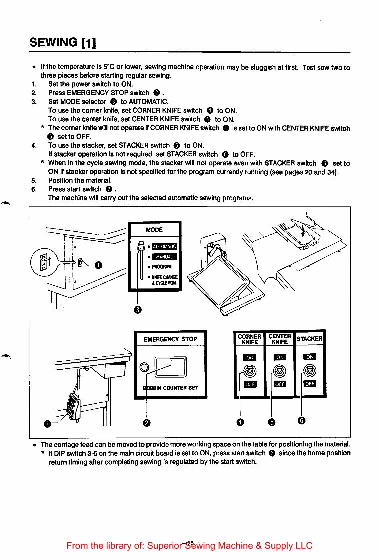
SEWING [1]
• If the temperature is soc or lower, sewing machine operation may be sluggish at first. Test sew two to three pieces before starting regular sewing.
1. Set the power switch to ON. 2. Press EMERGENCY STOP switch f) . 3. Set MODE selector 0 to AUTOMATIC.
To use the corner knife, set CORNER KNIFE switch 8 to ON. To use the center knife, set CENTER KNIFE switch 0 to ON.
* The corner knife will not operate If CORNER KNIFE switch 8 is set to ON with CENTER KNIFE switch 0 set to OFF.
4. To use the stacker, set STACKER switch 8 to ON. If stacker operation is not required, set STACKER switch 8 to OFF.
* When in the cycle sewing mode, the stacker will not operate even with STACKER switch (f) set to ON If stacker operation Is not specified for the program currently running (see pages 20 and 34).
5. Position the material. 6. Press start switch 0 .
The machine will carry out the selected automatic sewing programs.
MODE
,.., 1 •1·1111·1~1!·1111
• 1~!·!11•!·!· • PROGRAM
• KNIFE CHANGE &CYa.EPGM.
EMERGENCY STOP CORNER CENTER STACKER KNIFE KNIFE
0,....... ~- -E paaiN COUNTER SET
• The carriage feed can be moved to provide more working space on the table for positioning the material. * If DIP switch 3-6 on the main circuit board Is set to ON, press start switch 0 since the home position
return timing after completing sewing is regulated by the start switch.
-25-From the library of: Superior Sewing Machine & Supply LLC
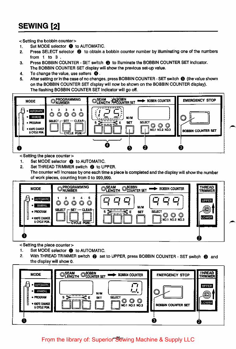
SEWING [2]
<Setting the bobbin counter> 1. Set MODE selector 0 to AUTOMATIC. 2. Press SELECT selector 8 to obtain a bobbin counter number by illuminating one of the numbers
from 1 to 3 . 3. Press BOBBIN COUNTER - SET switch 0 to illuminate the BOBBIN COUNTER SET Indicator.
The BOBBIN COUNTER SET display will show the previous set-up value. 4. To change the value, use setters 8. 5. After setting or In the case of no changes, press BOBBIN COUNTER -SET switch e (the value shown
on the BOBBIN COUNTER SET display will now be shown on the BOBBIN COUNTER display). The flashing BOBBIN COUNTER SET indicator will go off.
MODE @PROGRAMMING NUMBER @~g~TH -~~SET ... BOBBIN COUNTER EMERGENCY STOP
l\ •l·!•il·l~1!·!111 1 2 3 4 5 '''''-__!''''''" [ l ... '1 -, ,-:. @@@@© ~. ;- -;: I •'.t!o!mHM -~-y "_,,~ /:;,,, ~ ... ~ M/M
• PROGRAM S ~---__!:; E SET SELECT (Q) @ @ iD[EfOJ • KNifE CHANGE DOD ~ N0.1 N0.2 N0.3 BOBBIN COUNTER SET &CYCLE PGM. CYCLE PGM.
' J
v
0 8 - 4~ 8
<Setting the piece counter> 1. Set MODE selector 0 to AUTOMATIC. 2. Set THREAD TRIMMER switch 8 to UPPER.
The counter will increase by one each time a piece is completed and the display will show the number of work pieces, counting from o to 999,999.
MODE @PROGRAMMING NUMBER
@SEAM @BOBBIN ... LENGTH COUNTER SET BOBBIN COUNTER
~ •1·!111·1~1!·1111 1 2 3 4· 5 ,-, ,-, ,-, ,-, ,-, ,-, ©©©>©© fff -;-;-; •IM"f!lf.!M M/M
• PROGRAM
iOQQLIQ.~ S >----~ E SET SELECT (Q) @ @ • KNIFE CHANGE DOD D II II N0.1 N0.2 N0.3 &CYa.EPGM.
4~
<Setting the piece counter> 1. Set MODE selector 0 to AUTOMATIC.
THREAD TRIMMER -t
2. With THREAD TRIMMER switch 8 set to UPPER, press BOBBIN COUNTER - SET switch 0 and the display will show o.
MODE (Q)SEAM (Q)BOBSIN EMERGENCY STOP THREAD LENGTH COUNTER SET ... BOBBIN COUNTER TRIMMER
.fi •1·!111•1!1!·1111 ( L,M ( ,-,) -~ I • MM'fllto!M ~ t '-'·
• PROGRAM S ~----~ E SET SELECT@ @ @ • KNIFE CHANG£ DOD 0 II II N0.1 N0.2 N0.3 BOBBIN COUNTER SET 111&1
& CYa.E PGII.
0
-26-From the library of: Superior Sewing Machine & Supply LLC

<Adjusting the stitch tension > 1. Bobbin thread tension
2. Needle thread tension
3. Thread take·UP spring
• Thread take-up spring operation range
• The bobbin thread tension varies with the material and thread. Turn tension regulating screw 0 to adjust the tension. The standard tension Is 40 to 50 g for m~cHum·thick to thick materials when sewing with #50 spun yarn.
• Turn tension control nuts 8 to adjust the needle thread tension. Once the bobbin thread tension has been adjusted, the needle thread tension adjustment alone can provide a well-balanced, neat seam.
o~H ? Well-balanced, neat seam
X~ {# Excessive needle thread tension
Z: or Insufficient bobbin thread tension
x?_ / f= H) /ij Insufficient needle thread tension ..._ or excessive bobbin thread tension
The standard operation range of thread take-up spring 0 is 7 to 1 0 mm. To adjust the range of spring 0, loosen screw 8 and turn stopper 8.
• Thread·take-up spring tension The standard thread take-up spring tension is 20 to 40 g. To adjust the tension, loosen screw 0 and setscrew 0 and turn tension stud 8.
-27-From the library of: Superior Sewing Machine & Supply LLC

CENTER KNIFE POSITION ADJUSTMENT
• Adjust the center knife positional correction value to suit the material thickness. The higher the center knife position number, the farther inside the knife is positioned.
Ex.: To change the sewing-start valueS from 0 to 3 and the sewing-end value E from 0 to 4 1. Change S (sewing start) value display 0 from "0" to "3". 2. Change E (sewing end) value display f) from "0" to "4".
* If the above changes are made before the sewing operation, they are valid whichever mode is selected.
q:J)i..J.llliiE CENTER K.
..
-28-
q:J)i..J.illiiE CENTER K.
Sawing start Sewing end
~--------------- - --~
- ---- --- -- - ------- -
s E
o-- -9 9- -o
From the library of: Superior Sewing Machine & Supply LLC

CORNER KNIFE POSITION ADJUSTMENT
• Adjust the corner knife positional correction value to suit the material thickness. The higher the corner knife position is, the father"inside the knife Is positioned.
Ex.: To change the sewing-start value S from 5 to 3 and the sewing-end value E from 5 to 4 1. Set MODE selector 0 to PROGRAM. 2. Press BOBBIN COUNTER - SET switch f) .
The BOBBIN COUNTER SET display will show the corner knife position. 3. Press setter 8 to display 3. 4. Press setter 8 to display 4. 5. Either press BOBBIN COUNTER - SET switch f) or move MODE selector 0 to any position but
PROGRAM, to store the corner knife positional correction data. The correction data remains unmodified if the power switch Is set to OFF without these operations.
* The corner knife will not operate if the CORNER KNIFE switch Is set to ON with the CENTER KNIFE switch set to OFF.
MODE ©)PROGRAMMING NUMBER
(Q)SEAM (Q)BOBBIN ... LENGTH COUNTER SET BOBBIN COUNTER
( ~ ·•Nmll 1 2 3 4 5 ,- ,-) ©)@©)©)@ ;:; - ~ •E@iii·IM M/M
~ } • PROGRAM O[QQJ S :?i----~ E SET SELECT ©) ©) @ • KNFE CHANGE D ~ ,, ,, N0.1 N0.2 N0.3
& CYCLE PGM.
!
0
Sawing start Sewing end
s E 3-Lf MIM ( l
o- -9 9- -o S ~---~ E SET SELECT@ ©) @
DOD D D N0.1 N0.2 N0.3
-29-From the library of: Superior Sewing Machine & Supply LLC

FLAP SENSOR SENSITIVITY ADJUSTMENT (BAS-611, BAS-612)
< Adjusting the flap sensor sensitivity > 1. Set MODE selector 0 to PROGRAM and set the seam length to 190 mm. 2. Set MODE selector 0 to MANUAL. 3. Position the material so as not to cause wear to the rubber cushion on the back of the carriage feed . 4. Press start switch f) .
Flap sensors 8 (both right and left) will start monitoring after the carriage feed is moved to the sewing start position.
5. Move the carriage feed forward by hand from where it stopped to where sensor window 0 is positioned under sensor 8 . Adjust the sensitivity as described under "Sensitivity adjustments" on the next page.
6. Move the carriage feed from position A to B (the full length of the sensor window) by hand and make sure that FLAP SENSOR indicators 0 and 0 do not illuminate.
7. When adjustment is completed, press EMERGENCY STOP switch 0. The carriage feed will return to the home position.
MODE
•I·DII·J~!·!II • •mr~nl•t·'• f • PROGRAM
• KNFE CHANGE & CYClE PGM.
4t
EMERGENCY STOP
Oy /
I B08BIN COUNTeR SET
4~
©SEAM @BOBBIN LENGTH COUNTER SET
I 1-1 ,-, t f ,_,
M/M
S 5 < E SET
DODD
75·:.0~:/ij
FLAP SENSOR
LEFT 8 A
;:-;;;;-;'=r=:~-,-=-=-="<-r=-,-=-:.~E=========p~ ~0
-30-From the library of: Superior Sewing Machine & Supply LLC
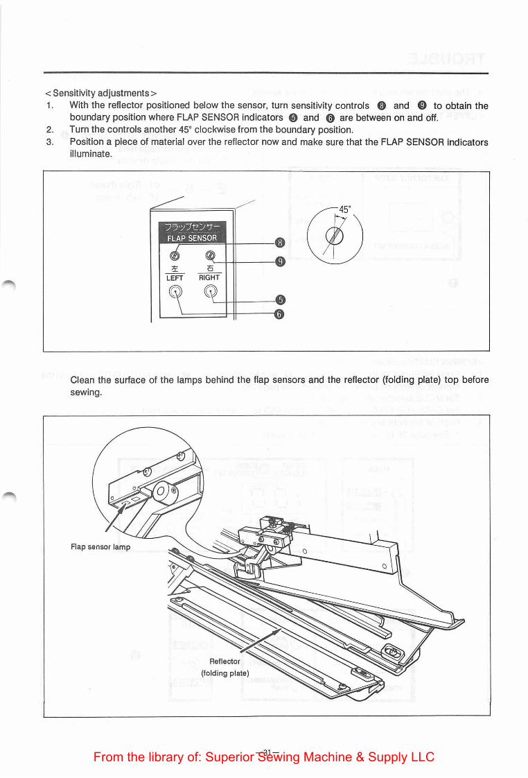
<Sensitivity adjustments> 1. With the reflector positioned below the sensor, turn sensitivity controls 0 and 0 to obtain the
boundary position where FLAP SENSOR indicators 0 and 0 are between on and off. 2. Turn the controls another 45° clockwise from the boundary position. 3. Position a piece of material over the reflector now and make sure that the FLAP SENSOR indicators
illuminate.
Clean the surface of the lamps behind the flap sensors and the reflector (folding plate) top before sewing.
Reflector
(folding plate)
-31-From the library of: Superior Sewing Machine & Supply LLC

TROUBLE
• The machine will stop if trouble occurs while sewing.
<UPPER THREAD BREAKAGE indicator illuminating>
1. Press EMERGENCY STOP switch 8 to advance the carriage feed.
2. Thread the needle threads.
EMERGENCY STOP TROUBLE
• UPPER THREAD
E _ 6 _ 01 Right thread 1 0 Left thread
~ ·I
BREAKAGE • © BOBBIN EMPTY I
BOBBIN COUNTER SET ©~MMING
0
<BOBBIN EMPTY indicator illuminating> 1. Press BOBBIN COUNTER -SET switch 8 with MODE selector 0 set to AUTOMATIC and input the
number of work pieces for the bobbin (see page 26). 2. Set MODE selector 8 to MANUAL 3. Set CARRIAGE FEED switch 0 to FORWARD to advance the carriage feed. 4. Replace the bobbin with a full one.
* See page 26 for resetting ~he bobbin counter .
MODE
k\ •I·!III•M!·!i II • lt'l!·!lll!·!· • PROGRAM
• KNIFE CHANGE &CYClE PGM.
4~
EMERGENCY STOP
oil II
BOBBIN COUNTER SET
.r\\SEAM -~BOBBIN ... BOBBIN COUNTER ~LENGTH ~OUNTER SET
,\\I I Ill I I II II I lilt"
:' I 1-1 II~ =flflf: ,,,,, '"i"l":":""'~''" M/M
S ~===~ E SET
DOD
TROUBLE
©~J:eREAD
• BOBBIN EMPTY
©~
-32-
( l
SELECT@ @ @
II II N0.1 N0.2 N0.3
CARRIAGE FEED
From the library of: Superior Sewing Machine & Supply LLC

<PROGRAMMING ERROR indicator illuminating> • BAS-611 machines: While programming, if the sewing data exceeds the 28 to 190 mm range while
programming or if the flap correction data is 50 mm or more, re-input the correct value (the range is 36 to 190 mm for a gauge width of 16 to 20 mm).
• BAS-612 machines: The indicator will illuminate if the following are programmed: · Seam length of less than 36 mm · Seam length of more than 190 mm The indicator will illuminate if the following are programmed with the PSW-31 switch set to ON:
A slant sewing program · Seam length of less than 28 mm · Seam length of more than 190 mm
• An indicator illuminating in the AUTOMATIC or MANUAL mode Trouble has occurred in the input data. Input the data in the PROGRAM mode.
MODE
~ • c.iiii•Mt.Jili • MM.Jdi(.)M
• PROGRAM
• KNIFE CHANGE &CYa.EPGM.
EMERGENCY STOP
(Q) D BOBBIN COUNTER SET
<EMERGENCY STOP indicator illuminating>
ON
sw31 32 33 34 35 36 37 38 DDDDDDDD
TROUBLE OFF
~ ~ c
©UPPER THREAD BREAKAGE
© BOBBIN EMPTY
• PROGRAMMING ERROR
* Press EMERGENCY STOP switch 0 to stop the carriage feed movement.
EMERGENCY STOP
ov /
BOBBIN COUNTER SET
Resetting after an emergency stop • Press the EMERGENCY STOP switch again to cut the needle thread and move the carriage feed to the
thread trimming position. The carriage feed will rise then and, at this time, the needle thread and bobbin thread trimmer knives can be operated. Press the EMERGENCY STOP switch again and press the start switch to return the carriage feed to the home position and to start sewing.
EMERGENCY STOP
BOBBIN COUNTER SET
-33-From the library of: Superior Sewing Machine & Supply LLC
STACKER OPERATION DURING CYCLE SEWING
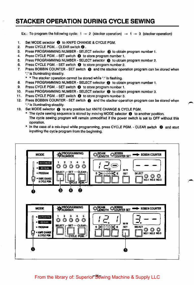
Ex.: To program the following cycle: 1 --+ 2 (stacker operation) --+ 1 --+ 3 (stacker operation)
1. Set MODE selector 0 to KNIFE CHANGE & CYCLE PGM. 2. Press CYCLE PGM. - CLEAR switch f) . 3. Press PROGRAMMING NUMBER- SELECT selector 8 to obtain program number 1. 4. Press CYCLE PGM. - SET switch 8 to store program number 1. 5. Press PROGRAMMING NUMBER - SELECT selector 8 to obtain program number 2. 6. Press CYCLE PGM. - SET switch 8 to store program number 2. 7. Press BOBBIN COUNTER - SET switch 8 and the stacker operation program can be stored when
11•
11 is illuminating steadily. * *The stacker operation cannot be stored while 11
•11 is flashing.
8. Press PROGRAMMING NUMBER - SELECT selector 8 to obtain program number 1. 9. Press CYCLE PGM. - SET switch G to store program number 1. 10. Press PROGRAMMING NUMBER- SELECT selector 8 to obtain program number 3. 11. Press CYCLE PGM. - SET switch 8 to store program number 3. 12. Press BOBBIN COUNTER- SET switch 8 and the stacker operation program can be stored when
11•
11 is illuminating steadily. 13. Set MODE selector 0 to any position but KNIFE CHANGE & CYCLE PGM.
* The cycle sewing sequence is stored by moving MODE selector 0 to another position. The cycle sewing program will remain unmodified if the power switch is set to OFF without this operation.
* In the case of a mis-input while programming, press CYCLE PGM. - CLEAR switch f) and start inputting the cycle program from the beginning .
MODE • ROGRAMMING UMBER @~~~TH @~g~~ SET ... BOBBIN COUNTER
•I·IIII•Jt~l!·lill 1 2 '3 4 5 (- -) I ..... ,_, .. ,,_ @@@@@ .-...~~- -• lf&il!lt·iM f ' ,,, ,,,,
~,., ~,, M/M
• PROGRAM
r~uSE~JJ S ~-----< E SET SELECT@ @ @
' ~ • KNFE CHANGE DOD D ,, II N0.1 N0.2 N0.3 ICYCLEPGM.
4~ 8 0 4~
MODE .ROGRAMMING UMBER @=TH @~:eR SET ... BOBBIN COUNTER
•II!II•J!I·III 1 2 3 4 5 I -1 (3.- -] I •*Mii!M+ @@@@© ,, f -. M/M
• PROGRAM O[QCJ DoD~ SELECT
D@@@ ~ ·~ • KNfE CHANGE N0.1 N0.2 N0.3 & CYCLE PGII.
4~ 4~
-34-From the library of: Superior Sewing Machine & Supply LLC

STANDARD ADJUSTMENTS [1] {Machine Head)
<Fitting a needle>
BAS-610 BAS-611
BAS-612 • Loosen screw 0 and Insert needle 8 all the
way in, with the long groove to the Inside.
0
Long groove
<Adjusting the upper and lower shaft timing>
Red dot
1. Remove the needle. 2. Tilt the machine head and remove timing belt 0 . 3. Align mark A on the pulley with the red dot. 4. Without moving the upper shaft, align the arrow mark on timing belt wheel assembly 8 with the arm
bed reference line and re- mount timing belt 0 . 5. Right the machine head and fit the needle. <Adjusting the needle and rotary hook timing>
[Clearance between the needle and rotary hook point]
Needle
Rotary hook point
~ax. 0.05mm
1. Loosen screws A , B , C and D and move the rotary hook base 0 sideways to Its approximate position (within 1 to 3 mm).
2. Tighten screw D and then adjust the clearance between the needle and the rotary hook point to 0.05 mm by turning adjustment screws 8 .
3. Fully tighten screws A , B and C after the adjustment. Note: • Secure lower shaft gear 8 by tightening setscrew C so that the gear lightly touch guide plate 8 .
Tighten setscrews C on lower shaft gears 8 so as not to change the screw stop.
-35-From the library of: Superior Sewing Machine & Supply LLC

STANDARD ADJUSTMENTS [2]
[Clearance between the rotary hook and needle plate]
• Loosen setscrews 8 and adjust the clearance between rotary hook 8 and needle plate 0 to 0.6 to 0.9 mm by moving rotary hook 8 vertically. [Needle bar lift stroke and needle bar height]
1. 1 1 to 1.5 mm
iOi 2.4mm If
Needle bar lift stroke 1. Loosen setscrews e and turn rotary hook 8 so as to adjust the rotary hook point to align with the
needle center when the needle rises 2.4 mm from its lowermost point. Needle bar height 1. Loosen setscrew 0 and move the needle bar vertically so as to adjust the clearance between the
needle hole top and the rotary hook point to 1 to 1.5 mm when the rotary hook point Is aligned with the needle hole center.
[Clearance between the rotary hook and bobbin case opener]
-36-
• Loosen bolts G and move bobbin case opener 0 sideways to adjust the clearance between rotary hook 8 and bobbin case opener 0 to 0.2 mm when bobbin case opener 0 pulled fully over in the arrowed direction.
From the library of: Superior Sewing Machine & Supply LLC
CARRIAGE FEED ADJUSTMENTS [1]
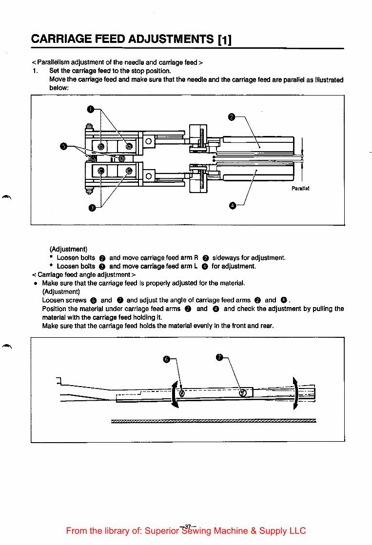
< Parallelism adjustment of the needle and carriage feed > 1. Set the carriage feed to the stop position.
Move the carriage feed and make sure that the needle and the carriage feed are parallel as Illustrated below:
(Adjustment) * Loosen bolts 8 and move carriage feed arm R 8 sideways for adjustment. * Loosen bolts 8 and move carriage feed arm L 8 for adjustment.
<Carriage feed angle adjustment> • Make sure that the carriage feed Is properly adjusted for the material.
(Adjustment) Loosen screws 8 and 0 and adjust the angle of carriage feed arms f) and 8 . Position the material under carriage feed arms 8 and 8 and check the adjustment by pulling the material with the carriage feed holding it. Make sure that the carriage feed holds the material evenly In the front and rear.
>tpff??&??????????Zf??22???2?????2????????f?Z???Z??ZZ??Z??Z22??2Z?
-37-From the library of: Superior Sewing Machine & Supply LLC
CARRIER FEED ADJUSTMENTS [2]
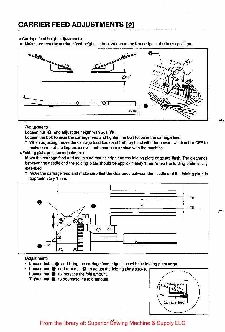
<Carriage feed height adjustment> • Make sure that the carriage feed height is about' 20 mm at the front edge at the home position.
20mm
r-----· - 0- - -
20mmt __________________________________ _!
(Adjustment) Loosen nut 0 and adjust the height with bolt 8 . Loosen the bolt to raise the carriage feed and tighten the bolt to lower the carriage feed. * When adjusting, move the carriage feed back and forth by hand with the power switch set to OFF to
make sure that the flap presser will not come Into contact with the machine. <Folding plate position adjustment>
Move the carriage feed and make sure that Its edge and the folding plate edge are flush. The clearance between the needle and the folding plate should be approximately 1 mm when the folding plate Is fully extended. * Move the carriage feed and make sure that the clearance between the needle and the folding plate Is
approximately 1 mm.
-J 1 mm : _______ _._; 1 mm
(Adjustment) · Loosen bolts 0 and bring the carriage feed edge flush with the folding plate edge. · Loosen nut 8 and turn nut 8 to adjust the folding plate stroke. r------------
Loosen nut 8 to increase the fold amount. Tighten nut 8 to decrease the fold amount.
-38-From the library of: Superior Sewing Machine & Supply LLC
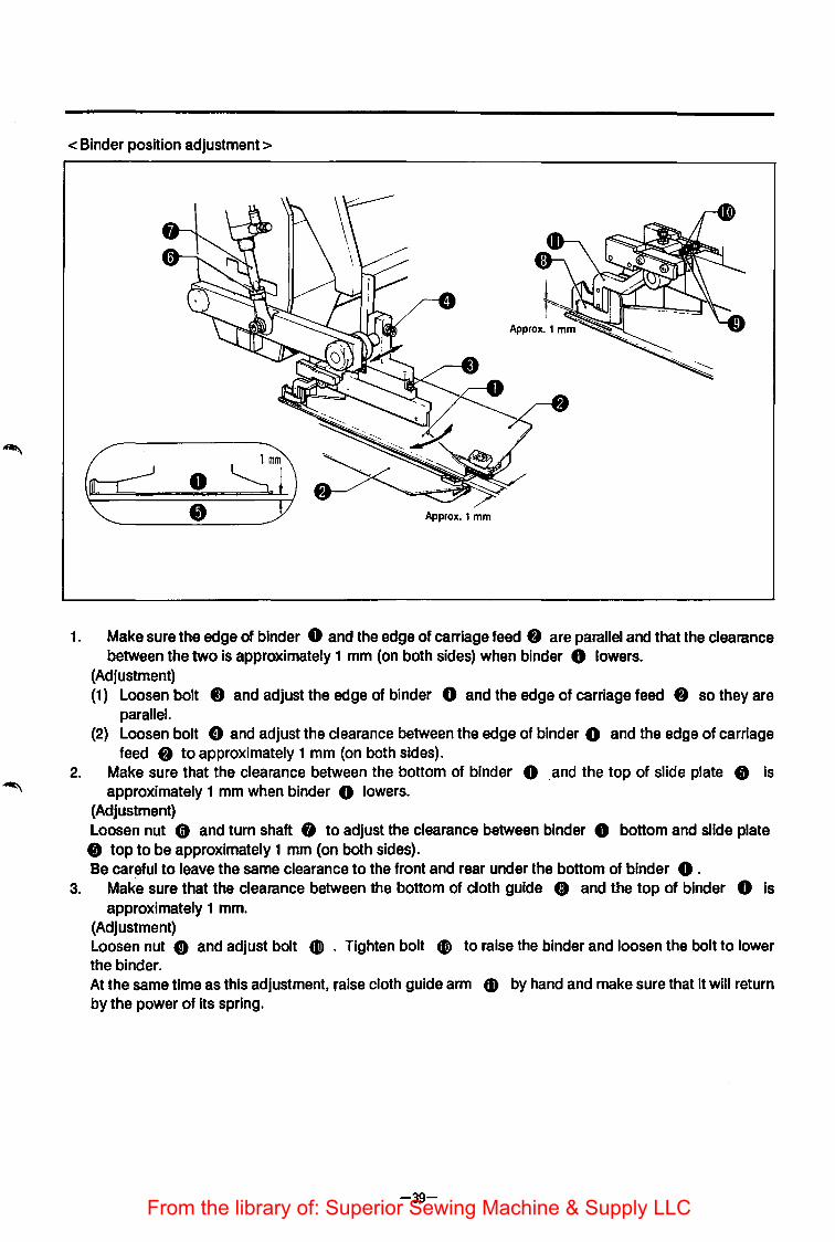
< Binder position adjustment>
Approx.1 mm
1. Make sure the edge of binder 0 and the edge of carriage feed f) are parallel and that the clearance between the two Is approximately 1 mm (on both sides) when binder 0 lowers.
(Adjustment) (1) Loosen bolt 8 and adjust the edge of binder 0 and the edge of carriage feed f) so they are
parallel. (2) Loosen bolt 8 and adjust the clearance between the edge of binder 0 and the edge of carriage
feed f) to approximately 1 mm (on both sides). 2. Make sure that the clearance between the bottom of binder 0 . and the top of slide plate 8 is
approximately 1 mm when binder 0 lowers. (Adjustment) Loosen nut 8 and turn shaft 0 to adjust the clearance between binder 0 bottom and slide plate 8 top to be approximately 1 mm (on both sides). Be careful to leave the same clearance to the front and rear under the bottom of binder 0 .
3. Make sure that the clearance between the bottom of cloth guide 0 and the top of binder 0 is approximately 1 mm.
(Adjustment) Loosen nut CD and adjust bolt CD . Tighten bolt CJ) to raise the binder and loosen the bolt to lower the binder. At the same time as this adjustment, raise cloth guide arm CD by hand and make sure that it will return by the power of its spring.
-39-From the library of: Superior Sewing Machine & Supply LLC

KNIFE REPLACEMENT [1]
<Corner knife replacement> 1. Set MODE selector 0 to KNIFE CHANGE. 2. Press EMERGENCY STOP switch 8.
An alarm will sound once and the carriage feed will move to the knife change position. The alarm will sound once again after the carriage feed stops.
3. Press EMERGENCY STOP switch 8 again. The alarm will sound twice and the carriage feed and the flap presser will lower; comer knife 8 will rise above the table. · * Keep your hands away from where the corner knife comes up .
.. AIR OFF .. will be displayed. 4. Close air cock 8 to stop the air supply (bleed the air line).
* The corner knife will be locked in the raised position. 5. Loosen setscrew 8 and replace comer knife 8 .
* To fit corner knife 3, align the knife edge with the edge of knife bracket 6. After replacing the knife, open air cock 8 to restore the air supply. 7. Press EMERGENCY STOP switch 8 .
The alarm will sound twice; the carriage feed and the flap presser will rise and corner knife 8 will be lowered. The carriage feed will move to the stop position and then the alarm will sound once.
MODE
•I!IIBI •E!mlll • PROGRAM
•KNR~ & CYa.E PGII.
EMERGENCY STOP
B0881N COUNTER SET
(Cautions on installation) · If the air supply is not turned on again in step 6 above, the corner knife will not be lowered even if the
air supply is restored later. If this happens, repeat steps 1 through 7 above. · If the corner knife is not In the center as illustrated, loosen screws 0 and adjust the angle of the
corner knife.
X _) ___________ (~
X -~----------~.
-40-From the library of: Superior Sewing Machine & Supply LLC

To replace the knife bracket unit:
t
-f)
IIJ!IiT--n-;....n.r.--=-o
lirt----.., A
Tllll •
To fit the knives:
-----------
1. Set MODE selector 0 to KNIFE CHANGE. 2. Loosen screws 0 by half a turn. 3. Press the EMERGENCY STOP switch twice.
The corner knife will rise above the table. 4. Close the air supply and replace knife bracket
unit 8. · * Be careful not to loosen the screws too far,
otherwise the knife bracket" unit will come into contact with slide guide 8 .
1. Loosen screws 0 and move knives S 8 in the arrowed directions; fit the knives according to the sewing pattern.
2. A maximum deviation of 4 mm can be set. 3. Finely adjust the distances to the seams by
changing the angles of the knives secured by set screws 8.
l _________ _ : --.),_____.
r-?L------Comer knife
Comer knife L Corner knife bracket unit
Corner knife types (knife bracket units are available as optional parts)
I Size 8 10 12 14 16 18 20 Comer knife 815881-001 S15882-()()1 S15883-()()1 S15884-001 S15885-001 S15886-001 815887-001 bracket unit
LR 809416-001 Corner knife
809417-001 LL SR 808322-001
Corner knife SL 808302.001
Ceramic L S14051.001 corner knife s 814050.001
-41-From the library of: Superior Sewing Machine & Supply LLC

KNIFE REPLACEMENT [2]
<Needle thread knife replacement>
CARRIAGE FEED MODE
~ •IPIJoiiHII j el,i,t.Jillt.!M
• PROGRAM
• KNFE CHANGE &CYa.EPGM.
0
(Caution on Installation)
1. 2.
3. 4.
5.
Set MODE selector 0 to MANUAL. Set CARRIAGE FEED switch to FORWARD and move the carriage feed to a position convenient for knife replacement. Set power switch to OFF.
·Remove screw 8 and remove movable knife 8. Remove screw 0 and remove fixed knife 8
* Reverse the order above to Install the knives.
· Adjust fixed knife 8 and spring 0 so as to leave no clearance over movable knife 8 , and to apply pressure evenly on knife 8 . * Increase the pressure If the knives do not cut properly.
· If the pressure is increased too much, movable knife operation will become sluggish or the needle threads will not be released smoothly.
-42-From the library of: Superior Sewing Machine & Supply LLC

<Bobbin thread knife replacement>
MODE
n • l·ilm!l,(.ili
) ~ • MMU!Il·iM
• PROGRAM
• KNHCHANG£ &CYCLEPGM.
CARRIAGE FEED
1. Set MODE selector 0 to MANUAL. 2. Set CARRIAGE FEED switch 8 to
FORWARD to advance the carriage feed. 3. Set power switch 8 to OFF. 4. Remove slide plates R and L 0 . 5. ·rut the machine head. 6. Loosen screws t) and remove screws 0 ;
remove knife bracket 0 . 7. Remove bobbin thread trimmer knives 0 .
* Reverse the order above to install. (Cautions on installation) · Install bobbin thread trimmer knives C) so that
it will not protrude from the needle plate top surface.
· Install bobbin thread trimmer knives 8 so that the knife grooves are aligned with the needle plate groove when the cylinder rod Is fully retracted.
THREAD TRIMMER
Bobbin thread
0
•
-43-From the library of: Superior Sewing Machine & Supply LLC
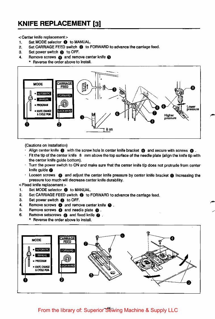
KNIFE REPLACEMENT [3]
<Center knife replacement> 1. Set MODE selector 0 to MANUAL 2. Set CARRIAGE FEED switch 8 to FORWARD to advance the carriage feed. 3. Set power switch 8 to OFF. 4. Remove screws 8 and remove center knife e
* Reverse the order above to Install.
MODE
• «·m<•Mt·ni • Mt&Uiit·'M
• PROGRAM
• KNIFE CHANGE &CYCLEPGM.
CARRIAGE FEED
(Cautions on installation)
Higher pressure
· Align center knife 8 with the screw hole in center knife bracket 8 and secure with screws 8 . · Fit the tip of the center knife 8 mm above the top surface of the needle plate (align the knife tip with
the center knife guide bottom). · Turn the power switch to ON and make sure that the center knife tip does not protrude from center
knife guide 8 · Loosen screws G and adjust the center knife pressure by center knife bracket • Increasing the
pressure too much will decrease center knife durability. < Fixed knife replacement> 1. Set MODE selector 0 to MANUAL. 2. Set CARRIAGE FEED switch 8 to FORWARD to advance the carriage feed. 3. Set power switch 8 to OFF. 4. Remove screws 8 and remove center knife e . 5. Remove screws 8 and needle plate e. 6. Remove setscrews e and fixed knife 8 .
* Reverse the order above to install.
MODE
• l·mle!f,J.jii
• lf,t.jJ!if.!M
• PROGRAM
• KN!FE CHANGE &CYCLEPGM.
CARRIAGE FEED
-44-From the library of: Superior Sewing Machine & Supply LLC

PARTS REPLACEMENT FOR SINGLE WELTING
. <When changing from double welting to single welti~g >
MODE i . H!iltBiilil • ~~~!·!Ill!·!· • PROGRAM
• KNIFE CHANGE &CYa.EPGM.
1. Set MODE selector 0 to MANUAL and advance the carriage feed to the thread trimming position. 2. Replace the binder assembly for double welting with the one for single welting and press the treadle
forward to adjust the height by operating the binder assembly. 3. Loosen screws f) on ruler fitting plate L 0 and remove spacer W 8 . 4. Slide ruler fitting plate L towards carriage feed arm L 8 and firmly tighten screws f) . 5. Release the air pressure and remove spacer W 0 inserted onto the rod of the cylinder for folding
plate L. 6. Set the manual valve 0 for folding plateR to OFF (down).
* Set the manual valve to ON for single welt sewing for flap attachment.
-45-From the library of: Superior Sewing Machine & Supply LLC
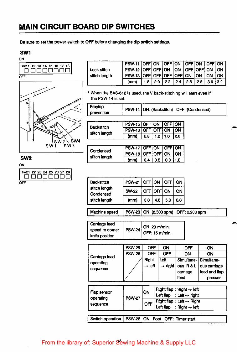
MAIN CIRCUIT BOARD DIP SWITCHES
Be sure to set the power switch to OFF before changing the dip switch settings.
SW1 ON
sw11 12 13 14 15 16 17 18 DDDDDDDD
OFF
~ ~1: ,,
I.
'I II I
f)'
SW2 ON
SWl
sw21 22 23 24 25 26 27 28 DDDDDDDO
OFF
PSW-11 OFF ON OFF ON OFF ON OFF Lock-stitch PSW-12 OFF OFF ON ON OFF OFF ON stitch length PSW-~3 OFF OFF OFF OFF ON ON ON
(mm) 1.8 2.0 2.2 2.4 2.6 2.8 3.0
*When the BAS-612 is used, the V back-stitching will start even if the PSW-14 is set.
Fraying prevention
Backstitch stitch length
Condensed stitch length
Backstitch stitch length Condensed stitch length
PSW-14 ON: (Backstitch) OFF: (Condensed)
PSW-15 OFF ON OFF ON PSW-16 OFF OFF ON ON (mm) 0.8 1.2 1.6 2.0
PSW-17 OFF ON OFF ON PSW-18 OFF OFF ON ON
(mm) 0.4 0.6 0.8 1.0
PSW-21 OFF ON OFF ON
SW-22 OFF OFF ON ON
(mm) 3.0 4.0 5.0 6.0
I Machine speed I PSW-231 ON: (2,500 spm) OFF: 2,200 spm
Carriage feed ON: 20 m/mln.
speed to comer PSW-24 OFF: 15 m/mln.
knife position
PSW-25 OFF ON OFF ON PSW-26 OFF OFF ON ON
ON ON ON 3.2
Carriage feed operating v
Right Left Simultane- Slmultane---.left --.right ous R & L ous carriage
sequence carriage feed and flap feed presser
Flap sensor ON Right flap : Right --. left
operating PSW-27 Left flap : Left --. right Right flap : Left --. Right
sequence OFF Left flap : Right --. left
I Switch operation I PSW-281 ON: Foot OFF: Timer start
-46-From the library of: Superior Sewing Machine & Supply LLC

SW3 ON
sw31 32 33 34 35 36 37 38 DDDDDDDD
OFF
* For the BAS-612, use the machine with the PSW-31 off.
SW4 ON
sw41 42 43 44 45 46 47 48 DDDDDDDD
OFF
* For the BAS-612, use the machine with the PSW-31 off.
BAS-61 0·611 BAS-612 Gauge PSW-31 ON: 8, 10, 12, 14 mm ~
OFF: 16, 18,20 mm 8-20 mm
PSW-32 OFF ON OFF ON PSW-33 OFF OFF ON ON
Operation after No Stop at cor- lmme- Re-sewing
thread breakage moni- ner knife dlate toring position stop
PSW-34 OFF ON OFF ON Stacker type PSW-35 OFF OFF ON ON
Pick-up Bar Roller Air
Carrier feed PSW-36 ON: Start SW monitored
position
I PSW-37 I ON: Sensor initialization Check routine
f PSW-38 f ON: Memory initialization
PSW-41 ON: Dart spreading PSW-42 ON: co·rner knife safety device PSW-43 ON: Automatic welt cloth mounting PSW-44 ON: Automatic flap mounting
Options PSW-45 ON: Corner knife used (for slant sewina) PSW-46 Soare PSW-47 Spare PSW-48 ON: N Backstitch OFF: V Back-stitch
-47-From the library of: Superior Sewing Machine & Supply LLC

WHEN CHANGING THE TREADLE OPERATION TO TIMER SWITCH CON-ROL
• Turn off dip switch 2-8. • When running a flap program, the machine will not operate on pressing the start switch unless the flap
presser is lowered. • For standard sewing, the machine will operate on pressing the start switch after the folding plate has
operated. • Set the MODE selector either to AUTOMATIC or to MANUAL. • Input programs with the MODE selector set to AUTOMATIC.
<Treadle operation> ~ 1. Press treadle 0 backwards to raise padding cloth presser foot springs R 8 and L 0 . 2. Release treadle 0 to lower padding cloth presser foot springs R 8 and L 0 . 3. Press treadle 0 forward to position 0 to lower carriage feed arm L 8 . 4. Continue pressing treadle 0 at position 1, for 0.5 seconds, to lower carriage feed arm R 8 . 5. Continue pressing treadle 0 at position 1, for 1. 7 seconds, to lower binder 8 and operate the
folding plate. * The folding plate will start to operate 0.25 to 0.35 seconds after binder8is lowered.
6. Continue pressing treadle 0 at position 1, for 1.5 seconds, to lower flap presser L 8 . 7. Continue pressing treadle 0 at position 1, for 1 second, to lower flap presser R • . 8. Press START switch 8 to operate the carriage feed.
* The carriage feed and other mechanisms will not be reset even If the treadle is released at steps 3 to 7. Press treadle 0 backwards to reset.
* If the MODE selector Is set to MANUAL, the carriage feed will operate without actual sewing. * The sequence of carriage feed and flap presser operations (steps 3, 4, 6 and 7 above) can be
changed by setting the dip switches (see page 50).
-48-From the library of: Superior Sewing Machine & Supply LLC
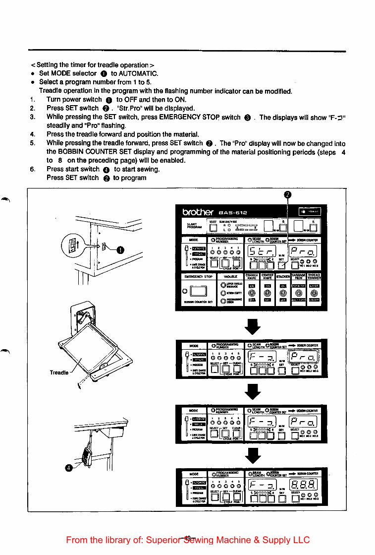
< Setting the timer for treadle operation > • Set MODE selector 0 to AUTOMATIC. • Select a program number from 1 to 5.
Treadle operation In the program with the flashing number indicator can be modified. 1. Turn power switch 0 to OFF and then to ON. 2. Press SET switch 8. "Str.Pron will be displayed. 3. While pressing the SET switch, press EMERGENCY STOP switch 8 . The displays will show 11F-='"
steadily and "Pro .. flashing. 4. Press the treadle forward and position the material. 5. While pressing the treadle forward, press SET switch 8 . The .. Pro .. display will now be changed into
the BOBBIN COUNTER SET display and programming of the material positioning periods (steps 4 to 8 on the preceding page) will be enabled.
6. Press start switch G to start sewing. Press SET switch 8 to program
IIIOOE o~ING @=TH ()~SET ~ IIOBIIIICOtlllD
r- 1 2 3 • !l r~- I u ,-, J§ .... ©>©>©>CO ~-~ :,-,-,-;: -• M/M - -• :
• PIICICIIWI O[Q:QJ s~a:::::(E SET 'lmCr()@'@' ·-awa ODD 0 D~1 NCt2..,., ICtCIJIIQI.
IIIOOE ©>~ @=TH @~SET ~ IIOIIIIINCOOOSI r- 1 2 3 4 5 IF - ::1.) M/M [P ,- o.) .... ©>©>©>©>©> • PIIOGIWI 5mCT Q SET-CUAU s ::;;_::::c I! SET SB!CT@ ©> ©> ·-awu DODD 0 110.1110.2110.3 IC!Q.EPGII. DQJQ
MODE @==MMINO @=TH ~SET ~ IIOIIIIICOtlllD
r- 1 2 3 4 !l (F- ::l.)u/M (,9.a,9.] ·-- @@@00
• PIIOGIWI SBfCT USET -aaAU S ::;i ____ :'(E SET SBfCT 0 0@
·-OWCI DODO 0110.1~2111-1 lCtCIJIQI, OQJQ
-49-From the library of: Superior Sewing Machine & Supply LLC
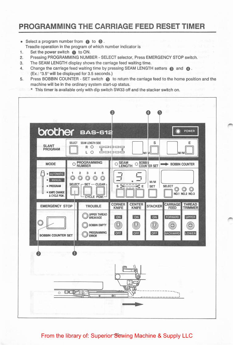
PROGRAMMING THE CARRIAGE FEED RESET TIMER
• Select a program number from 0 to 0 . Treadle operation in the program of which number indicator is
1. Set the power switch 0 to ON. 2. Pressing PROGRAMMING NUMBER -SELECT selector, Press EMERGENCY STOP switch. 3. The SEAM LENGTH display shows the carriage feed waiting time. 4. Change the carriage feed waiting time by pressing SEAM LENGTH setters 8 and 0 .
(Ex.: "3.5" will be displayed for 3.5 seconds.) 5. Press BOBBIN COUNTER -SET switch 0 to return the carriage feed to the home position and the
machine will be in the ordinary system start-up status. * This timer is available only with dip switch SW33 off and the stacker switch on.
SLANT PROGRAM
MODE
~ • f!iilleiXf·liiil
elt*&UIIMM
• PROGRAM
• KHHCHAHGE & CYClE PGM.
SELECT SEAM LENGTH SIDE
[I II : ~ O PROGRAMMING
NUMBER
1 2 3 4 5
©©©©©
~clOJQJ EMERGENCY STOP TROUBLE
A UPPER TliREAD ~BREAKAGE
© BOBBIN EMPTY
0~
• M/M [ l
s~::::::::::::~E SET SELECT© © © DODD [I II N0.1 N0.2 N0.3
CORNER KNIFE
m m m ~ ~ ~ ~ m rm rm
-50-From the library of: Superior Sewing Machine & Supply LLC

MEMORY INITIALIZATION
• Use this to initialize or clear the memory of back-up data necessary for sewing. 1. Set the power switch to OFF.
Set switch 3-8 on the main circuit board to ON. 2. Set the power switch to ON.
The memory will be completely cleared and standard data will be written. When writing Is completed, the alarm will sound once and program number Indicators 1 to 5 and bobbin counter Indicators 1 to 3 will illuminate.
3. Set the power switch to OFF. Set switch 3-8 on the main circuit board to OFF.
<Standard data contents>
Cycle sewing 1-+2-+3
Program 1 28 mm {36 mm)
Program 2 50mm
Program 3 100mm
Program 4 150mm
Program 5 190mm
Flap correction 1 40.0 mm
Flap correction 2 40.0 mm
Flap correction 3 40.0 mm
Flap correction 4 40.0 mm
Flap correction 5 40.0 mm
Corner knife correction 1 5--5
Corner knife correction 2 5--5
Corner knife correction 3 5--5
Corner knife correction 4 5--5
Corner knife correction 5 5-5
Bobbin thread 1 100
Bobbin thread 2 150
Bobbin thread 3 200
-51-From the library of: Superior Sewing Machine & Supply LLC
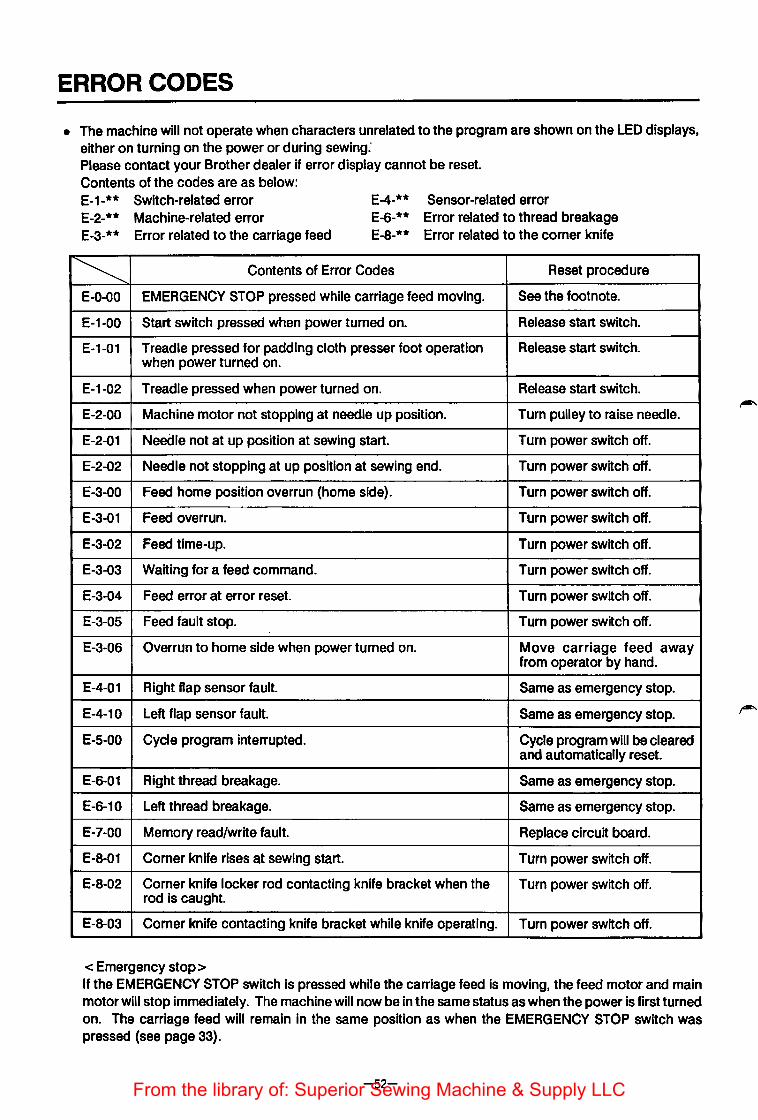
ERROR CODES
• The machine will not operate when characters unrelated to the program are shown on the LED displays, either on turning on the power or during sewing: Please contact your Brother dealer if error display cannot be reset. Contents of the codes are as below: E-1-** Switch-related error E-2-** Machine-related error
E-4-** Sensor-related error
E-3-** Error related to the carriage feed E-6-** Error related to thread breakage E-8-** Error related to the comer knife
~ Contents of Error Codes Reset procedure
E-0-00 EMERGENCY STOP pressed while carriage feed moving. See the footnote.
E-1-00 Start switch pressed when power turned on. Release start switch.
E-1-01 Treadle pressed for padding cloth presser foot operation Release start switch. when power turned on.
E-1-02 Treadle pressed when power turned on. Release start switch.
E-2-00 Machine motor not stopping at needle up position. Turn pulley to raise needle.
E-2-01 Needle not at up position at sewing start. Turn power switch off.
E-2-02 Needle not stopping at up position at sewing end. Turn power switch off.
E-3-00 Feed home position overrun (home side). Turn power switch off.
E-3-01 Feed overrun. Turn power switch off.
E-3-02 Feed time-up. Turn power switch off.
E-3-03 Waiting for a feed command. Turn power switch off.
E-3-04 Feed error at error reset. Turn power switch off.
E-3-05 Feed fault stop. Turn power switch off.
E-3-06 Overrun to home side when power turned on. Move carriage feed away from operator by hand.
E-4-01 Right flap sensor fault. Same as emergency stop.
E-4-10 Left flap sensor fault. Same as emergency stop.
E-5-00 Cycle program interrupted. Cycle program will be cleared and automatically reset.
E-6-01 Right thread breakage. Same as emergency stop.
E-6-10 Left thread breakage. Same as emergency stop.
E-7-00 Memory read/write fault. Replace circuit board.
E-8-01 Corner knife rises at sewing start. Turn power switch off.
E-8-02 Corner knife locker rod contacting knife bracket when the Turn power switch off. rod is caught.
E-8-03 Comer knife contacting knife bracket while knife operating. Turn power switch off.
<Emergency stop> If the eMERGENCY STOP switch is pressed while the carriage feed is moving, the feed motor and main motor will stop immediately. The machine will now be in the same status as when the power is first turned on. The carriage feed will remain In the same position as when the EMERGENCY STOP switch was pressed (see page 33).
-52-From the library of: Superior Sewing Machine & Supply LLC

TROUBLE-SHOOTING
Phenomenon I Cause [ Where to check I Solution I Page
Bent needle, blunt tip Needle Replace needle
Incorrect needle fitting Needle facing Re-fit needle correctly
Needle thread See •Threading the
breaks Incorrect threading Threading·
needle thread 11
Excessive needle thread Needle thread tension See •Stitch tension•
tension
Incorrect clearance between rotary hook and bobbin case opener
See •Needle and rotary hook timings adjustment-
Incorrect needle and rotary See "Needle and
hook timing rotary hook timing adjustment"
Incorrect threading Threading See 11Threading the
needle threads"
Bobbin thread Excessive bobbin thread Bobbin thread tension Correctly tighten ad~ustment screw
breaks tension tig tening screw
Oil, waste threads on Clean away all waste
bobbin case surface threads and oil
Uneven stitches Bent needle, blunt tip Needle Replace needle
Bent needle, blunt tip Needle Replace needle
Incorrect needle fitting Needle facing, height See "Fitting the
needle"
Skipped stitches Incorrect threading Needle thread threading See •Threading the
needle threads•
Incorrect timing of needle See •Needle and
and rotary hook rotary hook timing adjustment•
Trimmings collected Clean around
around rotary hook rotary hook
Weak thread take-up Thread take-up spring See 11Stitch tension• sprin,9 or its limited
workmg range power, action
Stitches do not Insufficient needle thread Needle thread tension See •Stitch tension"
tighten tension
. Insufficient bobbin thread Bobbin thread tension See •stitch tension•
tension
Incorrect needle fitting Needle facing, height See •fitting the
needle•
Needle breaks Bent needle, blunt tip Needle Replace needle
Incorrect needle and rotary See •Needle and
hook timing rotary hook timing adjustment•
Needle doesn't Needle up stop element Needle up stop element See •Position detector stoP. at up
fault position adjustment• position.
-53-From the library of: Superior Sewing Machine & Supply LLC

BROTHER INDUSTRIES, L TO. NAGOYA, JAPAN
151-61 0·611 612
893611-102 1993.8 H ®
Printed in Japan/Gedruckt in Japan/lmprime au Japon/lmpreso en Jap6n
From the library of: Superior Sewing Machine & Supply LLC