Embed Size (px)
Citation preview

AUTOMATICFOOD SERVICE
EQUIPMENT
AUTOMATIC GAS BROILERMODEL 9025 (CCSI CONTROL)
OWNERS MANUALIMPORTANT: RETAIN THIS MANUAL IN A SAFE PLACE
FOR FUTURE REFERENCE.
Broiler area must be kept free of combustible materials, and the flow of combustion and ventilation airmust not be obstructed. Operating personnel must not perform any maintenance or repair functions.Contact your Nieco Authorized Dealer.
In a prominent location, post instructions to be followed in the event the user smells gas. This informa-tion shall be obtained by consulting your local gas supplier.
FOR YOUR SAFETY:
Do not store or use gasoline or other flammable vapors or liquids inthe vicinity of this or any other appliance.
WARNING: Improper installation, adjustment, alteration, maintenancecan cause property damage, injury, or death. Read the installation,
operating and maintenance instructions thoroughly before installingor servicing this equipment.
2
TABLE OF CONTENTS
A. General Information . . . . . . . . . . . . . . . . . . . . . . . . . . . . . . . . . . . . . . . . .3A.1 Description . . . . . . . . . . . . . . . . . . . . . . . . . . . . . . . . . . . . . . . . . . .3A.2 Warranty Information . . . . . . . . . . . . . . . . . . . . . . . . . . . . . . . . . . .3A.3 Service/Technical Assistance . . . . . . . . . . . . . . . . . . . . . . . . . . . . .4A.4 Safety Information . . . . . . . . . . . . . . . . . . . . . . . . . . . . . . . . . . . . .4
B. Machine Installation . . . . . . . . . . . . . . . . . . . . . . . . . . . . . . . . . . . . . . . . .6B.1 Pre-Installation . . . . . . . . . . . . . . . . . . . . . . . . . . . . . . . . . . . . . . . .6B.2 Mounting . . . . . . . . . . . . . . . . . . . . . . . . . . . . . . . . . . . . . . . . . . . .6B.3 Leveling . . . . . . . . . . . . . . . . . . . . . . . . . . . . . . . . . . . . . . . . . . . . .6B.4 Hood Requirements . . . . . . . . . . . . . . . . . . . . . . . . . . . . . . . . . . . .7B.5 Clearance . . . . . . . . . . . . . . . . . . . . . . . . . . . . . . . . . . . . . . . . . . .7B.6 Gas Connection . . . . . . . . . . . . . . . . . . . . . . . . . . . . . . . . . . . . . . .8B.7 Flexible Gas Line Installation . . . . . . . . . . . . . . . . . . . . . . . . . . . . .8B.8 Restraining Device . . . . . . . . . . . . . . . . . . . . . . . . . . . . . . . . . . . . .9B.9 Electrical Connection . . . . . . . . . . . . . . . . . . . . . . . . . . . . . . . . . . .9B.10 Pre-Operation Check . . . . . . . . . . . . . . . . . . . . . . . . . . . . . . . . . . .9
C. Operation . . . . . . . . . . . . . . . . . . . . . . . . . . . . . . . . . . . . . . . . . . . . . . . . .10C.1 Controls and Indicators . . . . . . . . . . . . . . . . . . . . . . . . . . . . . . . . .10C.2 Step-by-Step Lighting Procedure . . . . . . . . . . . . . . . . . . . . . . . . .12C.3 Shutdown Procedure . . . . . . . . . . . . . . . . . . . . . . . . . . . . . . . . . .14C.4 Control Operation . . . . . . . . . . . . . . . . . . . . . . . . . . . . . . . . . . . . .15
D. Assembly/Disassembly and Cleaning . . . . . . . . . . . . . . . . . . . . . . . . . .20
E. Troubleshooting Guide . . . . . . . . . . . . . . . . . . . . . . . . . . . . . . . . . . . . . .39
F. Broil Chain Tension & Link Removal . . . . . . . . . . . . . . . . . . . . . . . . . . .42
G. Parts and Locations . . . . . . . . . . . . . . . . . . . . . . . . . . . . . . . . . . . . . . . .43G.1 Main Chamber Removable Parts . . . . . . . . . . . . . . . . . . . . . . . . .43G.2 Flex Chamber Removable Parts . . . . . . . . . . . . . . . . . . . . . . . . . .44G.3 Feed End View Components . . . . . . . . . . . . . . . . . . . . . . . . . . . . .45G.4 Main Chamber Side View Components . . . . . . . . . . . . . . . . . . . . .46G.5 Flex Chamber Side View Components . . . . . . . . . . . . . . . . . . . . .47G.6 Model 9025 Parts List . . . . . . . . . . . . . . . . . . . . . . . . . . . . . . . . . .48
H. Wiring Diagram . . . . . . . . . . . . . . . . . . . . . . . . . . . . . . . . . . . . . . . . . . . .49
I. Specifications . . . . . . . . . . . . . . . . . . . . . . . . . . . . . . . . . . . . . . . . . . . . .50
J. Warranty Information . . . . . . . . . . . . . . . . . . . . . . . . . . . . . . . . . . . . . . .52
Nieco Corporation - Model 9025
3
A. GENERAL INFORMATION
A.1 Description
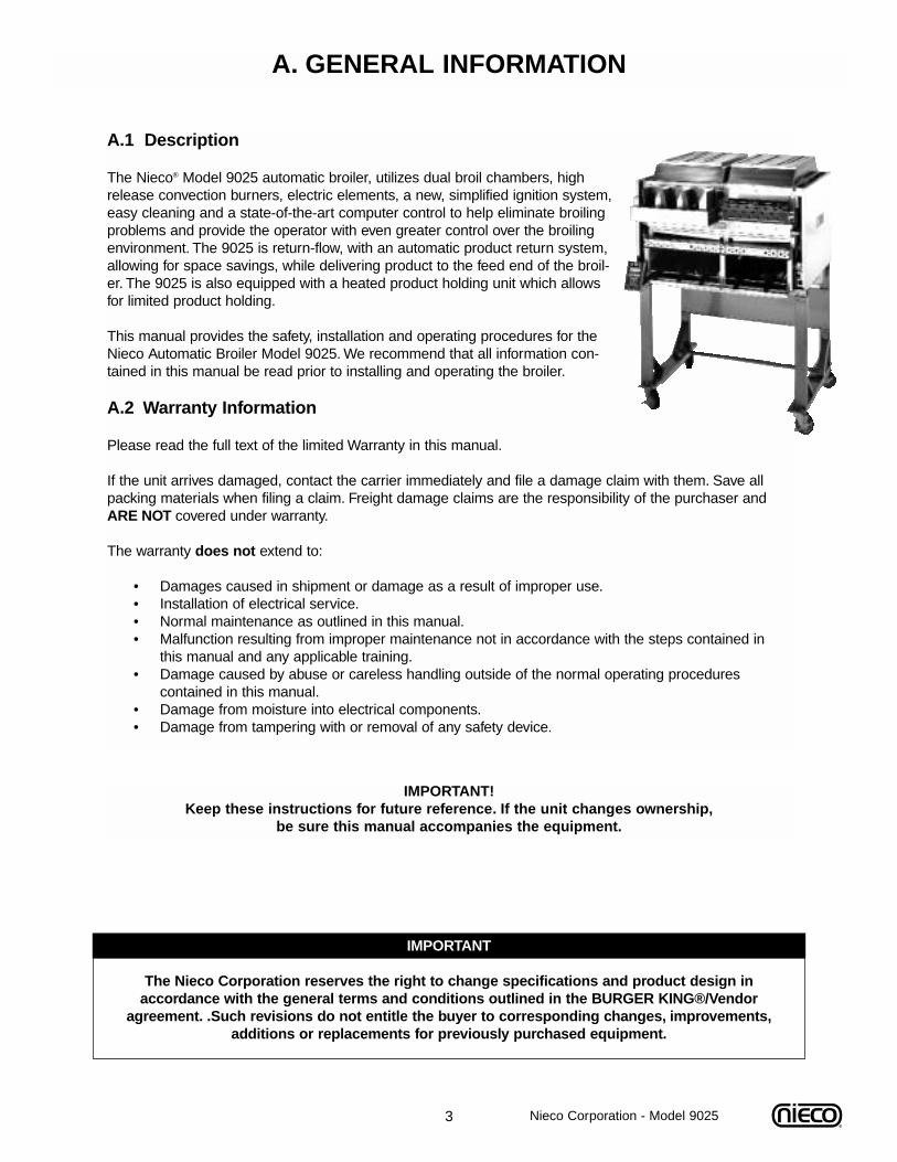
The Nieco® Model 9025 automatic broiler, utilizes dual broil chambers, highrelease convection burners, electric elements, a new, simplified ignition system,easy cleaning and a state-of-the-art computer control to help eliminate broilingproblems and provide the operator with even greater control over the broiling environment. The 9025 is return-flow, with an automatic product return system,allowing for space savings, while delivering product to the feed end of the broil-er. The 9025 is also equipped with a heated product holding unit which allowsfor limited product holding.
This manual provides the safety, installation and operating procedures for theNieco Automatic Broiler Model 9025. We recommend that all information con-tained in this manual be read prior to installing and operating the broiler.
A.2 Warranty Information
Please read the full text of the limited Warranty in this manual.
If the unit arrives damaged, contact the carrier immediately and file a damage claim with them. Save allpacking materials when filing a claim. Freight damage claims are the responsibility of the purchaser andARE NOT covered under warranty.
The warranty does not extend to:
• Damages caused in shipment or damage as a result of improper use.• Installation of electrical service.• Normal maintenance as outlined in this manual.• Malfunction resulting from improper maintenance not in accordance with the steps contained in
this manual and any applicable training.• Damage caused by abuse or careless handling outside of the normal operating procedures
contained in this manual.• Damage from moisture into electrical components.• Damage from tampering with or removal of any safety device.
IMPORTANT! Keep these instructions for future reference. If the unit changes ownership,
be sure this manual accompanies the equipment.
IMPORTANT
The Nieco Corporation reserves the right to change specifications and product design in accordance with the general terms and conditions outlined in the BURGER KING®/Vendor
agreement. .Such revisions do not entitle the buyer to corresponding changes, improvements,additions or replacements for previously purchased equipment.
Nieco Corporation - Model 9025
4
A.3 Service/Technical Assistance
If you experience any problems with the installation or operation of your broiler, contact your localAuthorized Nieco Distributor.
Fill in the information bellow and have it handy when calling your authorized service agency for assistance.The serial number is on the broiler rating plate on the side of the unit.
Purchased from:
Date of Purchase:
Model No.:
Serial No.:
For the name of your local Authorized Nieco Distributor, please call (800) 821-2141.
Use only genuine Nieco replacement parts in your broiler. Use of replacement parts other than those sup-plied by Authorized Nieco Distributors and Service Agencies will void the warranty and may significantlyalter the performance of your broiler. Nieco and the Burger King Corporation have worked together to cre-ate a set of standards for broiler performance, food quality and food safety. The use of non-Nieco parts iscapable of affecting these criteria, and may affect broiler performance, parts longevity and food safety.Yourlocal Authorized Nieco Distributor and Service Agent has been factory trained and has a complete supplyof parts for your Nieco Automatic Broiler.
You may contact the factory direct at (707) 284-7100 if you have trouble locating your local NiecoDistributor.
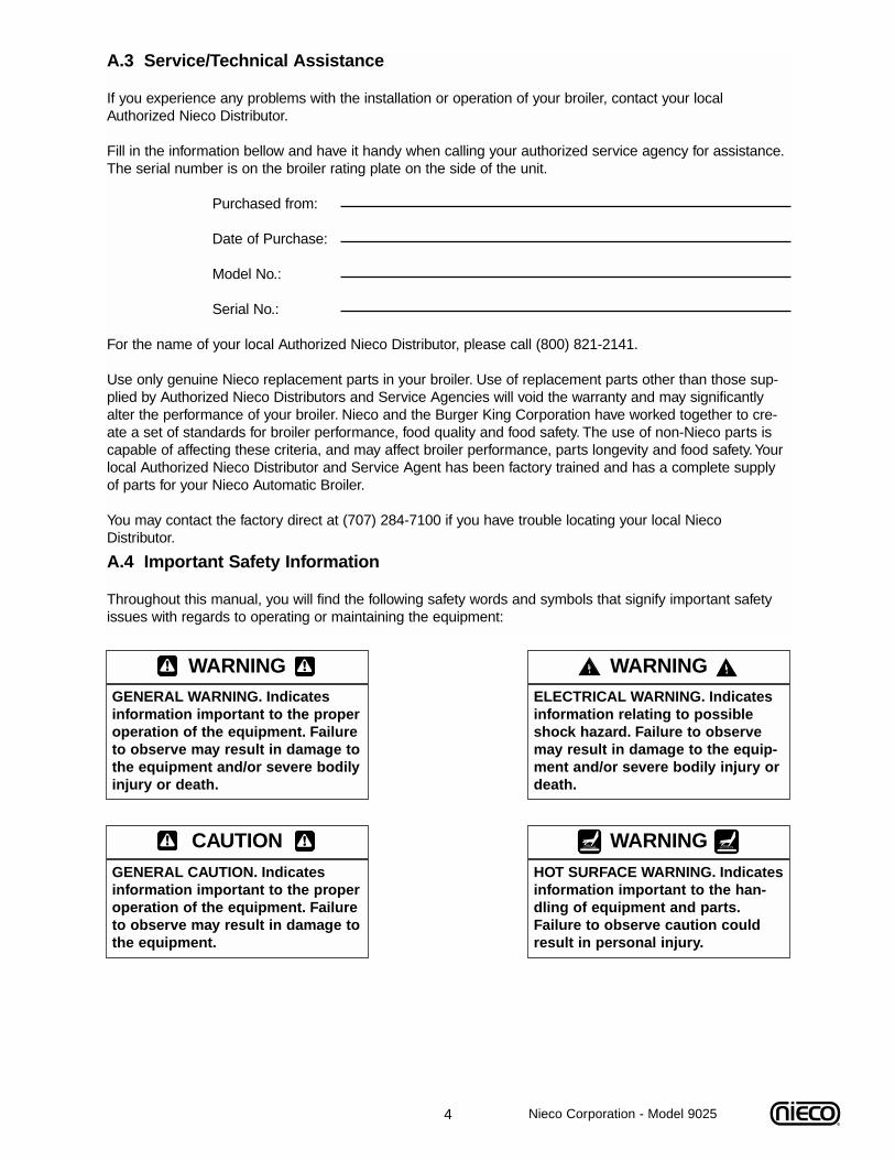
A.4 Important Safety Information
Throughout this manual, you will find the following safety words and symbols that signify important safetyissues with regards to operating or maintaining the equipment:
WARNINGGENERAL WARNING. Indicatesinformation important to the properoperation of the equipment. Failureto observe may result in damage tothe equipment and/or severe bodilyinjury or death.
WARNINGELECTRICAL WARNING. Indicatesinformation relating to possibleshock hazard. Failure to observemay result in damage to the equip-ment and/or severe bodily injury ordeath.
CAUTIONGENERAL CAUTION. Indicatesinformation important to the properoperation of the equipment. Failureto observe may result in damage tothe equipment.
WARNINGHOT SURFACE WARNING. Indicatesinformation important to the han-dling of equipment and parts.Failure to observe caution couldresult in personal injury.
Nieco Corporation - Model 9025
5
A.4 Important Safety Information (Cont.)
In addition to the warnings and cautions in this manual, use the following guidelines for safe operation ofyour Nieco Automatic Broiler:
• Read and follow all instructions before using this equipment.• Install or locate broiler only for its intended use as described in this manual.• Do not operate this equipment if it has a damaged cord or plug, if it is not working properly or if it
has been otherwise damaged.• This equipment should only be serviced by authorized personnel. Contact your local Nieco
Distributor for adjustment or repair.• Use only genuine Nieco replacement parts for your broiler. Failure to do so will void the warranty
and may significantly alter the performance of your broiler. Nieco and the Burger King Corporation have worked together to create a set of standards for broiler performance, food qualityand food safety. The use of non-Nieco parts is capable of affecting these criteria, and may affect broiler performance, parts longevity and food safety.
The following warnings and cautions appear throughout the manual and should be carefullyobserved:
• Turn the broiler off, close the main gas valve, and disconnect the plug before performing any service, maintenance or cleaning on the broiler.
• Always allow the broiler to fully cool before performing any service, maintenance or cleaning. Failure to wait for the broiler to cool fully may result in personal injury.
• The procedures in this manual may include reference to the use of chemical products. The Nieco Corporation does not endorse the use of any particular cleaning/degreasing agent.Use only those chemicals that are approved for use in the BURGER KING® SYSTEM.
• The broiler should be grounded according to local electrical codes to prevent the possibility of electrical shock. It requires a grounded receptacle with separate electrical lines, protected by fuses or circuit breakers of the proper rating.
• All electrical connections must be in accordance with local electrical codes and any other applicable codes.
• The use of adequate ventilation (as rated in this manual) with this broiler is mandatory.Failure to adequately ventilate this unit and provide safe operating distances (as specified in this manual) is a fire safety hazard. Follow the instructions for emergency broiler shutdown in the event of an emergency.
• No attempt should be made to operate this appliance in the event of a power failure.
WARNING ELECTRICAL SHOCK HAZARD. FAILURE TO FOLLOW THESE INSTRUCTIONS COULDRESULT IN SERIOUS INJURY OR DEATH:
_ Electrical ground is required on this appliance._ Check with a qualified electrician if you are in doubt as to whether the appliance is properly
grounded._ Do not use water on or near the control box located on the underside of the broiler for risk
of serious injury or death due to electrical shock.
WARNING, HIGH TEMPERATURES WITH HOT SURFACES. FAILURE TO FOLLOW THESE PROCE-DURES COULD RESULT IN SERIOUS INJURY:
_ Do not attempt to clean, disassemble or perform maintenance on this broiler until it is fully cooled as per the instructions contained in this manual.
Nieco Corporation - Model 9025
6 Nieco Corporation - Model 9025
B. INSTALLATIONB.1 Pre-InstallationUncrate the broiler and inspect for shipping damage. Remove the tape securing the machine parts, andinstall the parts in their proper location. Refer to the Parts and Location section of this manual. If thereare obvious or concealed damages to any part of the broiler, please contact your freight carrier. The fac-tory warranty does not cover freight damage.
B.2 MountingFollow the mounting instructions if this function is not performed by the installer.
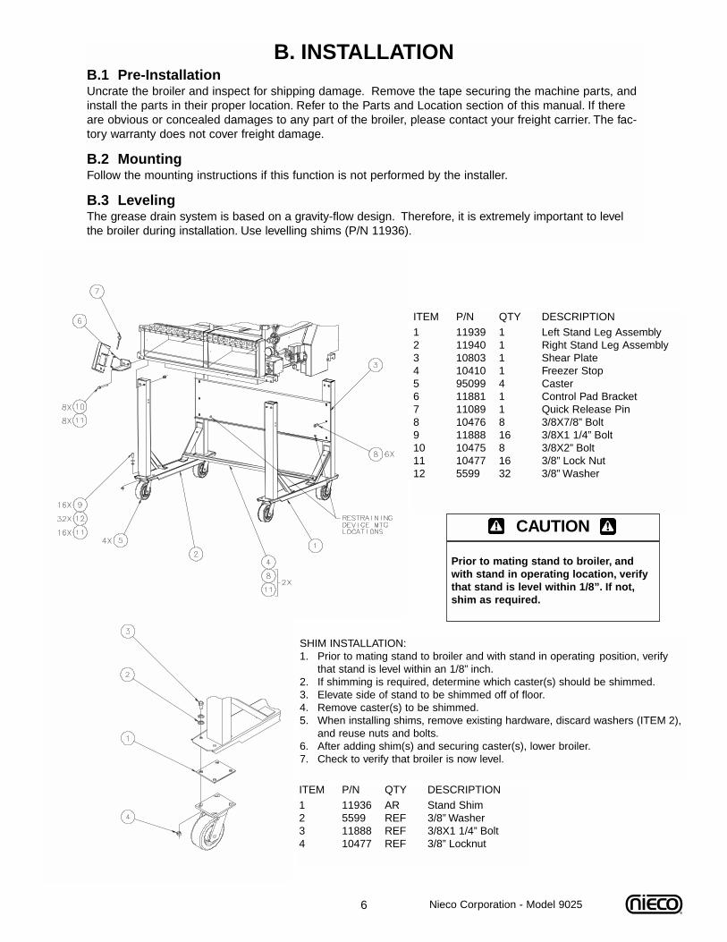
B.3 LevelingThe grease drain system is based on a gravity-flow design. Therefore, it is extremely important to levelthe broiler during installation. Use levelling shims (P/N 11936).
ITEM P/N QTY DESCRIPTION1 11939 1 Left Stand Leg Assembly2 11940 1 Right Stand Leg Assembly3 10803 1 Shear Plate4 10410 1 Freezer Stop5 95099 4 Caster6 11881 1 Control Pad Bracket7 11089 1 Quick Release Pin8 10476 8 3/8X7/8” Bolt9 11888 16 3/8X1 1/4” Bolt10 10475 8 3/8X2” Bolt11 10477 16 3/8” Lock Nut12 5599 32 3/8” Washer
CAUTION
Prior to mating stand to broiler, andwith stand in operating location, verifythat stand is level within 1/8”. If not,shim as required.
SHIM INSTALLATION:1. Prior to mating stand to broiler and with stand in operating position, verify
that stand is level within an 1/8” inch.2. If shimming is required, determine which caster(s) should be shimmed.3. Elevate side of stand to be shimmed off of floor.4. Remove caster(s) to be shimmed.5. When installing shims, remove existing hardware, discard washers (ITEM 2),
and reuse nuts and bolts.6. After adding shim(s) and securing caster(s), lower broiler.7. Check to verify that broiler is now level.
ITEM P/N QTY DESCRIPTION1 11936 AR Stand Shim2 5599 REF 3/8” Washer3 11888 REF 3/8X1 1/4” Bolt4 10477 REF 3/8” Locknut
7 Nieco Corporation - Model 9025
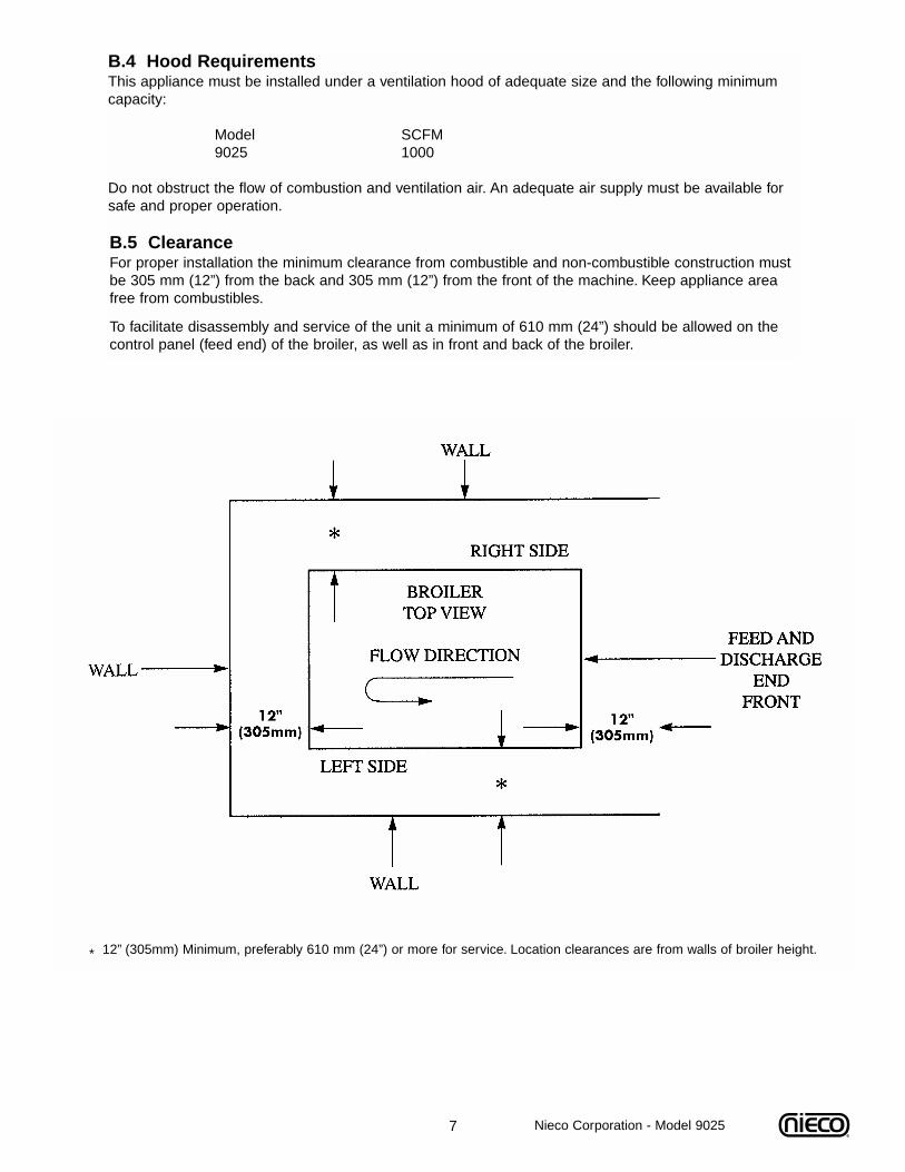
* 12” (305mm) Minimum, preferably 610 mm (24”) or more for service. Location clearances are from walls of broiler height.
B.4 Hood RequirementsThis appliance must be installed under a ventilation hood of adequate size and the following minimumcapacity:
Model SCFM9025 1000
Do not obstruct the flow of combustion and ventilation air. An adequate air supply must be available forsafe and proper operation.
B.5 ClearanceFor proper installation the minimum clearance from combustible and non-combustible construction mustbe 305 mm (12”) from the back and 305 mm (12”) from the front of the machine. Keep appliance areafree from combustibles.
To facilitate disassembly and service of the unit a minimum of 610 mm (24”) should be allowed on thecontrol panel (feed end) of the broiler, as well as in front and back of the broiler.
8
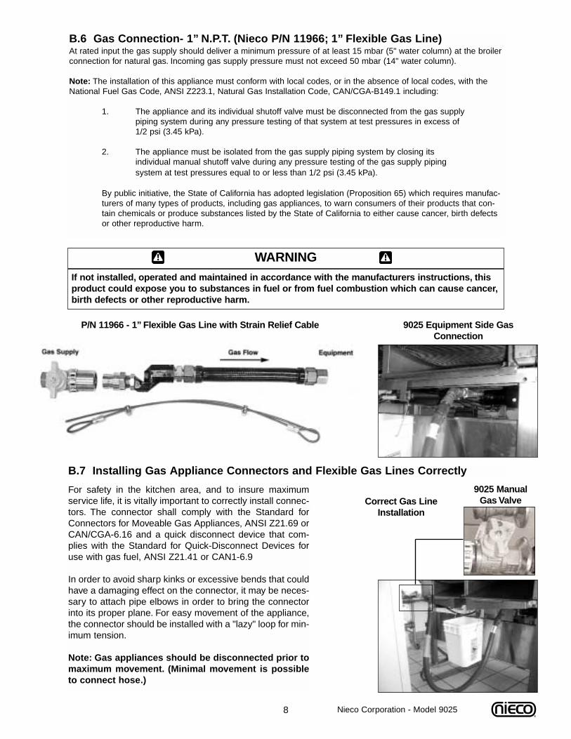
B.6 Gas Connection- 1” N.P.T. (Nieco P/N 11966; 1” Flexible Gas Line)At rated input the gas supply should deliver a minimum pressure of at least 15 mbar (5" water column) at the broilerconnection for natural gas. Incoming gas supply pressure must not exceed 50 mbar (14" water column).
Note: The installation of this appliance must conform with local codes, or in the absence of local codes, with theNational Fuel Gas Code, ANSI Z223.1, Natural Gas Installation Code, CAN/CGA-B149.1 including:
1. The appliance and its individual shutoff valve must be disconnected from the gas supply piping system during any pressure testing of that system at test pressures in excess of 1/2 psi (3.45 kPa).
2. The appliance must be isolated from the gas supply piping system by closing its individual manual shutoff valve during any pressure testing of the gas supply piping system at test pressures equal to or less than 1/2 psi (3.45 kPa).
By public initiative, the State of California has adopted legislation (Proposition 65) which requires manufac-turers of many types of products, including gas appliances, to warn consumers of their products that con-tain chemicals or produce substances listed by the State of California to either cause cancer, birth defectsor other reproductive harm.
Nieco Corporation - Model 9025
For safety in the kitchen area, and to insure maximumservice life, it is vitally important to correctly install connec-tors. The connector shall comply with the Standard forConnectors for Moveable Gas Appliances, ANSI Z21.69 orCAN/CGA-6.16 and a quick disconnect device that com-plies with the Standard for Quick-Disconnect Devices foruse with gas fuel, ANSI Z21.41 or CAN1-6.9
In order to avoid sharp kinks or excessive bends that couldhave a damaging effect on the connector, it may be neces-sary to attach pipe elbows in order to bring the connectorinto its proper plane. For easy movement of the appliance,the connector should be installed with a "lazy" loop for min-imum tension.
Note: Gas appliances should be disconnected prior tomaximum movement. (Minimal movement is possibleto connect hose.)
B.7 Installing Gas Appliance Connectors and Flexible Gas Lines Correctly
WARNINGIf not installed, operated and maintained in accordance with the manufacturers instructions, thisproduct could expose you to substances in fuel or from fuel combustion which can cause cancer,birth defects or other reproductive harm.
P/N 11966 - 1” Flexible Gas Line with Strain Relief Cable 9025 Equipment Side GasConnection
9025 Manual Gas ValveCorrect Gas Line
Installation
9 Nieco Corporation - Model 9025
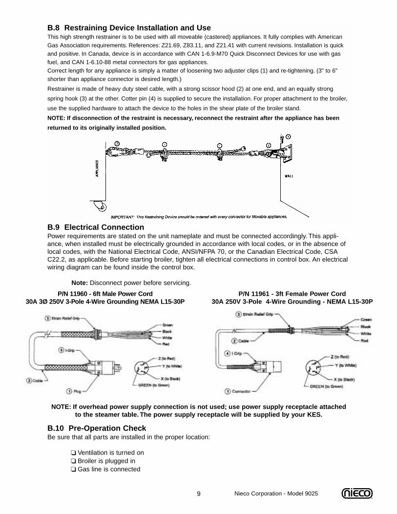
B.9 Electrical Connection Power requirements are stated on the unit nameplate and must be connected accordingly. This appli-ance, when installed must be electrically grounded in accordance with local codes, or in the absence oflocal codes, with the National Electrical Code, ANSI/NFPA 70, or the Canadian Electrical Code, CSAC22.2, as applicable. Before starting broiler, tighten all electrical connections in control box. An electricalwiring diagram can be found inside the control box.
Note: Disconnect power before servicing.
B.10 Pre-Operation CheckBe sure that all parts are installed in the proper location:
❏ Ventilation is turned on❏ Broiler is plugged in❏ Gas line is connected
B.8 Restraining Device Installation and UseThis high strength restrainer is to be used with all moveable (castered) appliances. It fully complies with AmericanGas Association requirements. References: Z21.69, Z83.11, and Z21.41 with current revisions. Installation is quickand positive. In Canada, device is in accordance with CAN 1-6.9-M70 Quick Disconnect Devices for use with gasfuel, and CAN 1-6.10-88 metal connectors for gas appliances.Correct length for any appliance is simply a matter of loosening two adjuster clips (1) and re-tightening. (3" to 6"shorter than appliance connector is desired length.)
Restrainer is made of heavy duty steel cable, with a strong scissor hood (2) at one end, and an equally strong
spring hook (3) at the other. Cotter pin (4) is supplied to secure the installation. For proper attachment to the broiler,
use the supplied hardware to attach the device to the holes in the shear plate of the broiler stand.
NOTE: If disconnection of the restraint is necessary, reconnect the restraint after the appliance has been
returned to its originally installed position.
P/N 11961 - 3ft Female Power Cord30A 250V 3-Pole 4-Wire Grounding - NEMA L15-30P
P/N 11960 - 6ft Male Power Cord30A 3Ø 250V 3-Pole 4-Wire Grounding NEMA L15-30P
NOTE: If overhead power supply connection is not used; use power supply receptacle attached to the steamer table. The power supply receptacle will be supplied by your KES.
10
C. OPERATION
C.1 Controls and Indicators
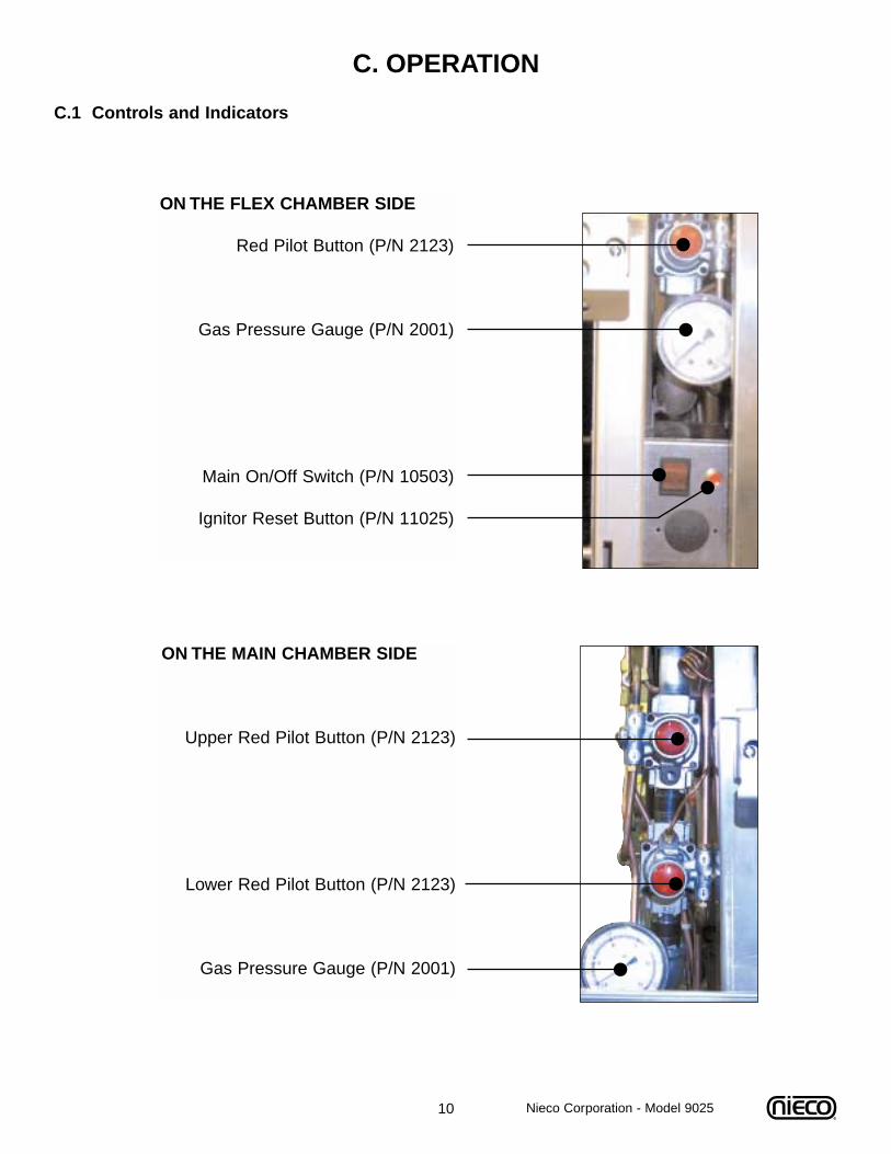
ON THE FLEX CHAMBER SIDE
Red Pilot Button (P/N 2123)
Gas Pressure Gauge (P/N 2001)
Main On/Off Switch (P/N 10503)
Ignitor Reset Button (P/N 11025)
ON THE MAIN CHAMBER SIDE
Upper Red Pilot Button (P/N 2123)
Lower Red Pilot Button (P/N 2123)
Gas Pressure Gauge (P/N 2001)
Nieco Corporation - Model 9025
11
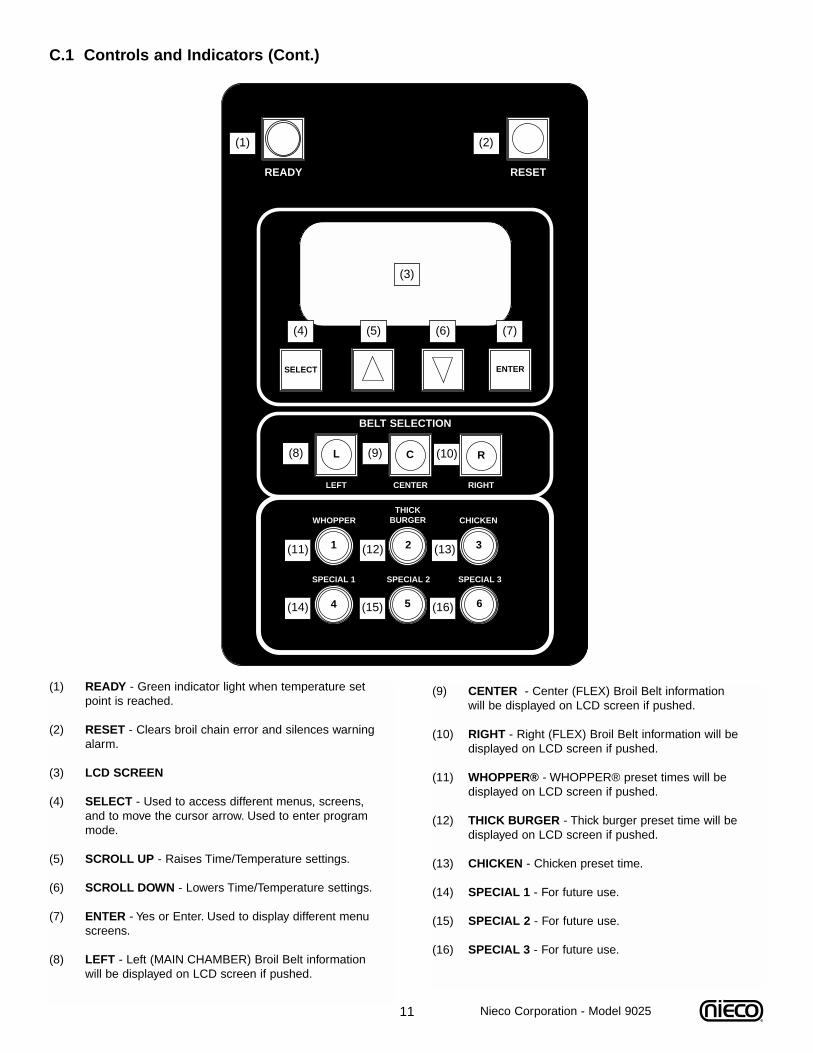
C.1 Controls and Indicators (Cont.)
(1) READY - Green indicator light when temperature set point is reached.
(2) RESET - Clears broil chain error and silences warning alarm.
(3) LCD SCREEN
(4) SELECT - Used to access different menus, screens, and to move the cursor arrow. Used to enter program mode.
(5) SCROLL UP - Raises Time/Temperature settings.
(6) SCROLL DOWN - Lowers Time/Temperature settings.
(7) ENTER - Yes or Enter. Used to display different menu screens.
(8) LEFT - Left (MAIN CHAMBER) Broil Belt information will be displayed on LCD screen if pushed.
(9) CENTER - Center (FLEX) Broil Belt information will be displayed on LCD screen if pushed.
(10) RIGHT - Right (FLEX) Broil Belt information will be displayed on LCD screen if pushed.
(11) WHOPPER® - WHOPPER® preset times will be displayed on LCD screen if pushed.
(12) THICK BURGER - Thick burger preset time will be displayed on LCD screen if pushed.
(13) CHICKEN - Chicken preset time.
(14) SPECIAL 1 - For future use.
(15) SPECIAL 2 - For future use.
(16) SPECIAL 3 - For future use.
READY
BELT SELECTION
LEFT
WHOPPERTHICK
BURGER CHICKEN
SPECIAL 1 SPECIAL 2 SPECIAL 3
CENTER RIGHT
SELECT ENTER
RESET
L
1 2 3
654
C R
(1) (2)
(4)
(9)(8) (10)
(11) (12) (13)
(14) (15) (16)
(5) (6) (7)
(3)
Nieco Corporation - Model 9025
12
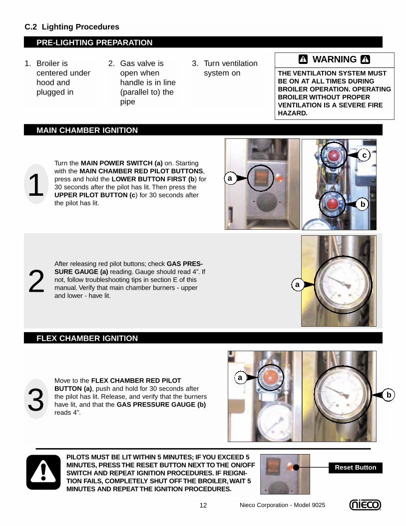
C.2 Lighting Procedures
1. Broiler is centered under hood and plugged in
2. Gas valve is open when handle is in line (parallel to) the pipe
3. Turn ventilation system on
PILOTS MUST BE LIT WITHIN 5 MINUTES; IF YOU EXCEED 5MINUTES, PRESS THE RESET BUTTON NEXT TO THE ON/OFFSWITCH AND REPEAT IGNITION PROCEDURES. IF REIGNI-TION FAILS, COMPLETELY SHUT OFF THE BROILER, WAIT 5MINUTES AND REPEAT THE IGNITION PROCEDURES.
Reset Button
1Turn the MAIN POWER SWITCH (a) on. Startingwith the MAIN CHAMBER RED PILOT BUTTONS,press and hold the LOWER BUTTON FIRST (b) for30 seconds after the pilot has lit. Then press theUPPER PILOT BUTTON (c) for 30 seconds afterthe pilot has lit.
2After releasing red pilot buttons; check GAS PRES-SURE GAUGE (a) reading. Gauge should read 4”. Ifnot, follow troubleshooting tips in section E of thismanual. Verify that main chamber burners - upperand lower - have lit.
3Move to the FLEX CHAMBER RED PILOTBUTTON (a), push and hold for 30 seconds afterthe pilot has lit. Release, and verify that the burnershave lit, and that the GAS PRESSURE GAUGE (b)reads 4”.
a
WARNINGTHE VENTILATION SYSTEM MUSTBE ON AT ALL TIMES DURINGBROILER OPERATION. OPERATINGBROILER WITHOUT PROPER VENTILATION IS A SEVERE FIREHAZARD.
MAIN CHAMBER IGNITION
b
c
PRE-LIGHTING PREPARATION
FLEX CHAMBER IGNITION
a
a
b
Nieco Corporation - Model 9025
13
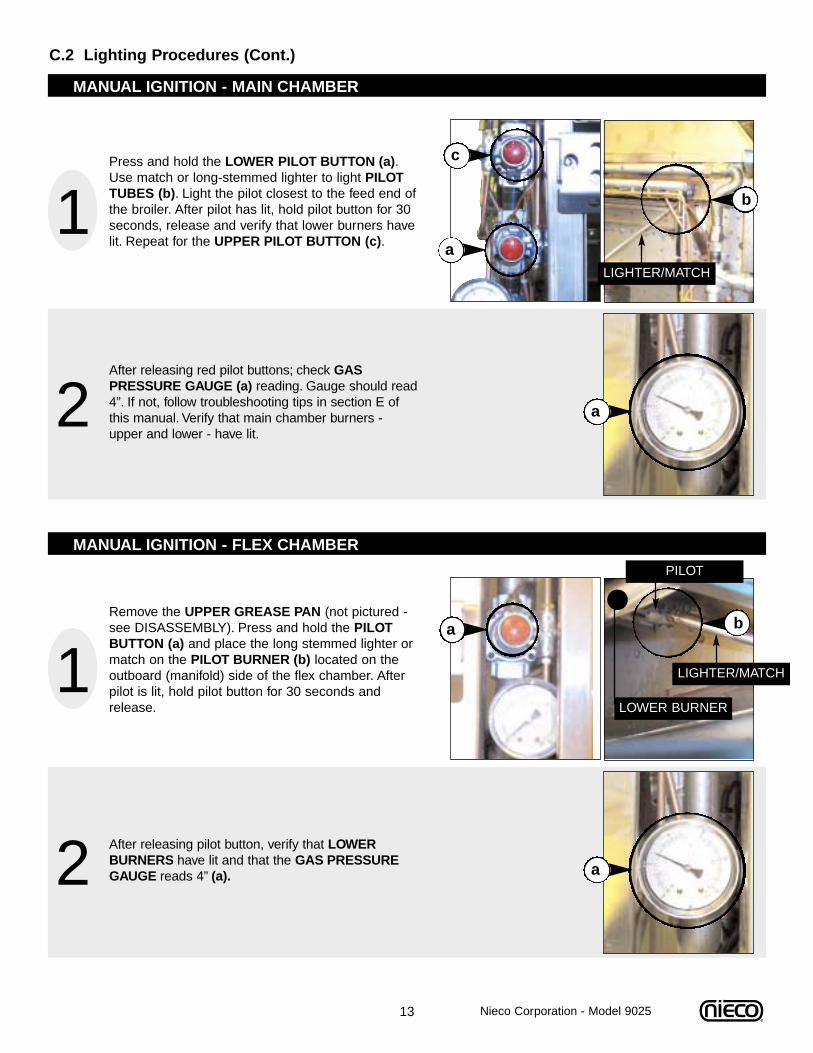
C.2 Lighting Procedures (Cont.)
MANUAL IGNITION - MAIN CHAMBER
1Press and hold the LOWER PILOT BUTTON (a).Use match or long-stemmed lighter to light PILOTTUBES (b). Light the pilot closest to the feed end ofthe broiler. After pilot has lit, hold pilot button for 30seconds, release and verify that lower burners havelit. Repeat for the UPPER PILOT BUTTON (c).
2After releasing red pilot buttons; check GAS PRESSURE GAUGE (a) reading. Gauge should read4”. If not, follow troubleshooting tips in section E ofthis manual. Verify that main chamber burners -upper and lower - have lit.
a
b
a
c
MANUAL IGNITION - FLEX CHAMBER
1Remove the UPPER GREASE PAN (not pictured -see DISASSEMBLY). Press and hold the PILOTBUTTON (a) and place the long stemmed lighter ormatch on the PILOT BURNER (b) located on theoutboard (manifold) side of the flex chamber. Afterpilot is lit, hold pilot button for 30 seconds andrelease.
2 After releasing pilot button, verify that LOWERBURNERS have lit and that the GAS PRESSUREGAUGE reads 4” (a).
a b
a
LOWER BURNER
Nieco Corporation - Model 9025
LIGHTER/MATCH
PILOT
LIGHTER/MATCH
14
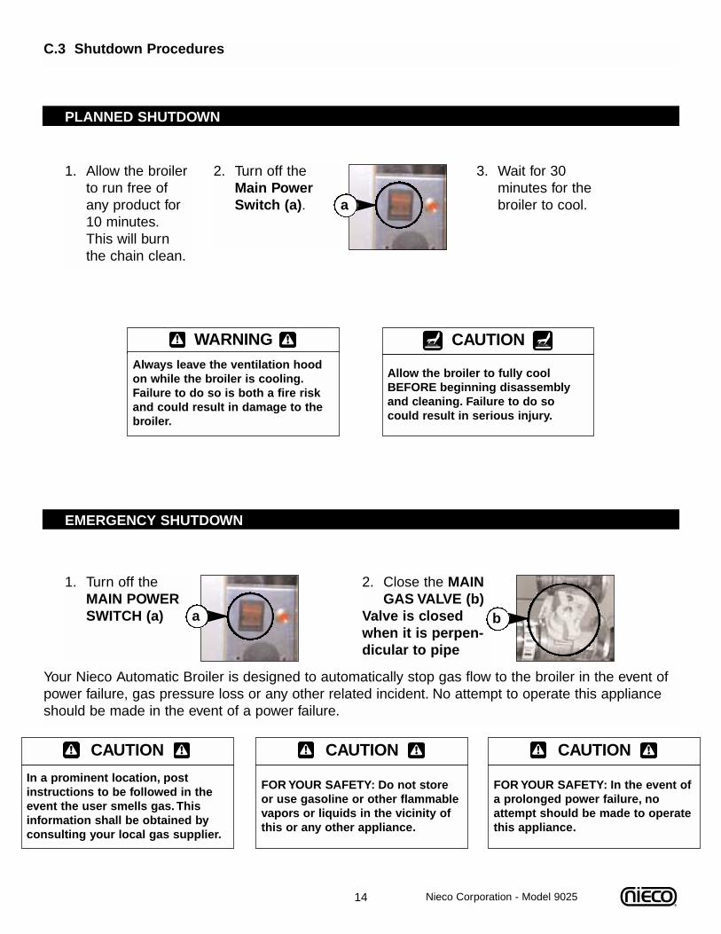
1. Allow the broilerto run free of any product for 10 minutes.This will burn the chain clean.
2. Turn off the Main Power Switch (a).
3. Wait for 30 minutes for the broiler to cool.
C.3 Shutdown Procedures
2. Close the MAINGAS VALVE (b)
Valve is closedwhen it is perpen-dicular to pipe
a
PLANNED SHUTDOWN
WARNINGAlways leave the ventilation hoodon while the broiler is cooling.Failure to do so is both a fire riskand could result in damage to thebroiler.
EMERGENCY SHUTDOWN
1. Turn off the MAIN POWER SWITCH (a) a b
Your Nieco Automatic Broiler is designed to automatically stop gas flow to the broiler in the event ofpower failure, gas pressure loss or any other related incident. No attempt to operate this applianceshould be made in the event of a power failure.
CAUTION
In a prominent location, postinstructions to be followed in theevent the user smells gas. Thisinformation shall be obtained byconsulting your local gas supplier.
CAUTION
FOR YOUR SAFETY: Do not storeor use gasoline or other flammablevapors or liquids in the vicinity ofthis or any other appliance.
Nieco Corporation - Model 9025
CAUTION
FOR YOUR SAFETY: In the event ofa prolonged power failure, noattempt should be made to operatethis appliance.
CAUTION
Allow the broiler to fully coolBEFORE beginning disassemblyand cleaning. Failure to do socould result in serious injury.
SELECT ENTER
15
SELECT ENTER
ACTUAL SET
MAIN xxxxF 0500F
FLEX xxxxF 0500F
SETUP EXIT
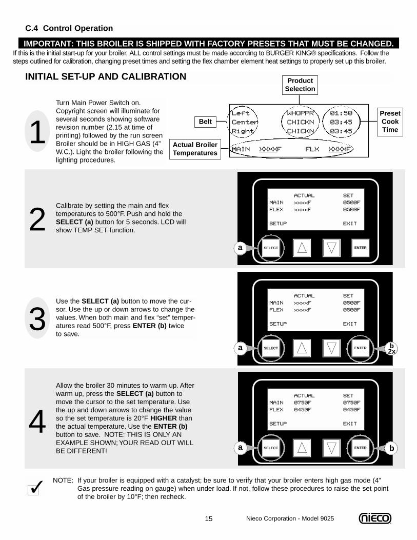
C.4 Control Operation
Left WHOPPR 01:50
Center CHICKN 03:45
Right CHICKN 03:45
MAIN XXXXF FLX XXXXF
1Turn Main Power Switch on.Copyright screen will illuminate forseveral seconds showing softwarerevision number (2.15 at time ofprinting) followed by the run screenBroiler should be in HIGH GAS (4”W.C.). Light the broiler following thelighting procedures.
2Calibrate by setting the main and flex temperatures to 500°F. Push and hold theSELECT (a) button for 5 seconds. LCD willshow TEMP SET function.
ACTUAL SET
MAIN xxxxF 0500F
FLEX xxxxF 0500F
SETUP EXIT3Use the SELECT (a) button to move the cur-sor. Use the up or down arrows to change thevalues. When both main and flex “set” temper-atures read 500°F, press ENTER (b) twice to save.
SELECT ENTER
ACTUAL SET
MAIN 0750F 0750F
FLEX 0450F 0450F
SETUP EXIT4Allow the broiler 30 minutes to warm up. Afterwarm up, press the SELECT (a) button tomove the cursor to the set temperature. Usethe up and down arrows to change the valueso the set temperature is 20°F HIGHER thanthe actual temperature. Use the ENTER (b)button to save. NOTE: THIS IS ONLY ANEXAMPLE SHOWN; YOUR READ OUT WILLBE DIFFERENT!
INITIAL SET-UP AND CALIBRATION
a
a
ba
Belt
ProductSelection
PresetCookTime
Actual BroilerTemperatures
IMPORTANT: THIS BROILER IS SHIPPED WITH FACTORY PRESETS THAT MUST BE CHANGED.If this is the initial start-up for your broiler, ALL control settings must be made according to BURGER KING® specifications. Follow the steps outlined for calibration, changing preset times and setting the flex chamber element heat settings to properly set up this broiler.
b2x
Nieco Corporation - Model 9025
NOTE: If your broiler is equipped with a catalyst; be sure to verify that your broiler enters high gas mode (4”Gas pressure reading on gauge) when under load. If not, follow these procedures to raise the set point of the broiler by 10°F; then recheck.

16
1
NORMAL RUN (OPERATING) SCREENS
The readout display actually has 8 lines, however only 4 are visible at a time. The first visible set shows cook times forthe upper broil chains. The second set shows the return belt time and the time and date stamp. To switch between thesets press the SELECT button.
SELECT ENTER
Left WHOPPR 01:50
Center CHICKN 03:45
Right CHICKN 03:45
FLX XXXXF MAIN XXXXF
RUN SCREEN 1Normal Run Screen
Press the SELECT (a) or ENTER (b) button untilthe screen returns to the normal run screen.Thenormal run screen shows cook times and broilertemperatures.
2SELECT ENTER
MN xxxxF xxxxF %=100
FL xxxxF xxxxF %=100
LPLT OPEN 0400F OFF
RPLT OPEN 0400F OFF
RUN SCREEN 2From the NORMAL RUN Screen Press
ENTER to get to Screen 2Run screen 2 compares the actual chamber versusthe programmed set points. This display is prima-rily used for service. To exit this screen andreturn to the normal operating screen pressSELECT (a) or ENTER (b).
Actual Temp
SetTemp
100% means gas valveis open all the way
3SELECT ENTER
RETURN BELT *OFF*
Platen Open*
Warmer Open*
Oct 5/00 xx:xx:xx
RUN SCREEN 3From the NORMAL RUN Screen press
SELECT to get to Run Screen 3Run screen 3 is diagnostic for service.To exit thisscreen and return to the normal operating screenpress SELECT (a) or ENTER (b).
ba
ba
ba
Nieco Corporation - Model 9025

17
1 BELT SELECTION
LEFT
THICK
CENTER RIGHT
SELECT ENTER
L C R
From the normal operating screen - pressand hold for 5 seconds the BELT you wish tochange. For example press LEFT (a).Belt selection choices are:LEFT (Main Chamber), CENTER and RIGHT(both Flex Chamber).
CHANGING PRESET COOK TIMESThe 9025 control allows you to program multiple belt speeds for each individual belt. Follow these steps to change thepreset broil times for each product/belt.
SELECT ENTER
Belt Preset# Time
Left WHOPPR 01:50
Htr1 Htr2
100% 100% Exit
2BELT SELECTION
LEFT
WHOPPERTHICK
BURGER CHICKEN
SPECIAL 1 SPECIAL 2 SPECIAL 3
CENTER RIGHT
L
1 2 3
C RThen press the PRODUCT button you wish tochange. For example select WHOPPER® (a).Product selection choices are:WHOPPER®, THICK BURGER, CHICKEN,SPECIAL 1, SPECIAL 2, SPECIAL 3.
3After step 1, the screen will change to the editmode with the cursor flashing on the presettime. Use the UP and DOWN (a) ARROWS toadjust the broil time. While in edit mode, anyof the belts and product preset times can bechanged. Simply press the BELT/PRODUCTyou wish to change and use the UP/DOWNarrows to change the times.
SELECT ENTER
Left CHICKN 03:45
Center CHICKN 03:45
Right WHOPPR 01:50
FLX XXXXF MAIN XXXXF4When you are finished making changes,press the ENTER (a) button TWICE (2x) tosave the changes and return to the normaloperating screen.
Cursor
a
a
a
a 2x
Nieco Corporation - Model 9025
18
1 BELT SELECTION
LEFT
WHOPPERTHICK
BURGER CHICKEN
CENTER RIGHT
SELECT ENTER
L
1 2 3
C R
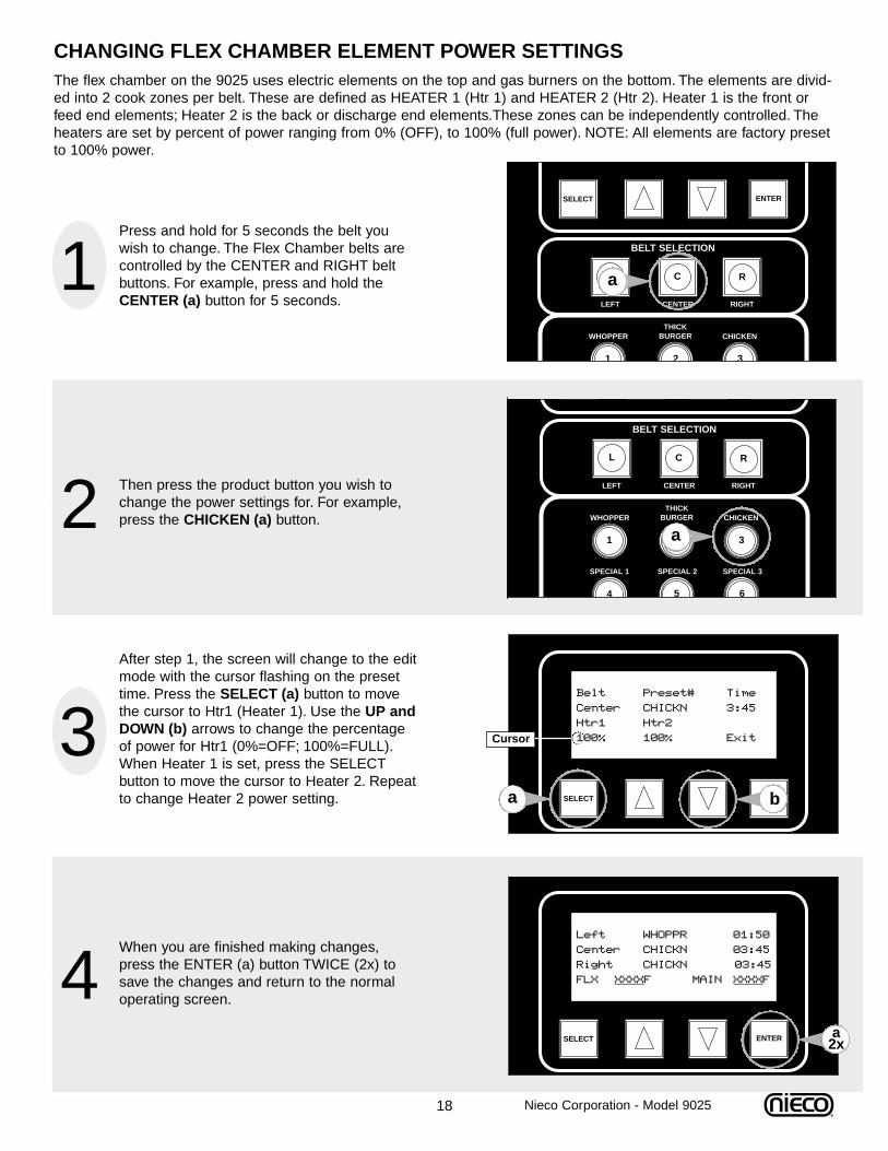
Press and hold for 5 seconds the belt youwish to change. The Flex Chamber belts arecontrolled by the CENTER and RIGHT beltbuttons. For example, press and hold theCENTER (a) button for 5 seconds.
CHANGING FLEX CHAMBER ELEMENT POWER SETTINGSThe flex chamber on the 9025 uses electric elements on the top and gas burners on the bottom. The elements are divid-ed into 2 cook zones per belt. These are defined as HEATER 1 (Htr 1) and HEATER 2 (Htr 2). Heater 1 is the front orfeed end elements; Heater 2 is the back or discharge end elements.These zones can be independently controlled. Theheaters are set by percent of power ranging from 0% (OFF), to 100% (full power). NOTE: All elements are factory presetto 100% power.
SELECT ENTER
Belt Preset# Time
Center CHICKN 3:45
Htr1 Htr2
100% 100% Exit
2BELT SELECTION
LEFT
WHOPPERTHICK
BURGER CHICKEN
SPECIAL 1 SPECIAL 2 SPECIAL 3
CENTER RIGHT
L
1 2 3
654
C R
Then press the product button you wish tochange the power settings for. For example,press the CHICKEN (a) button.
3After step 1, the screen will change to the editmode with the cursor flashing on the presettime. Press the SELECT (a) button to movethe cursor to Htr1 (Heater 1). Use the UP andDOWN (b) arrows to change the percentageof power for Htr1 (0%=OFF; 100%=FULL).When Heater 1 is set, press the SELECT button to move the cursor to Heater 2. Repeatto change Heater 2 power setting.
SELECT ENTER
Left WHOPPR 01:50
Center CHICKN 03:45
Right CHICKN 03:45
FLX XXXXF MAIN XXXXF4When you are finished making changes,press the ENTER (a) button TWICE (2x) tosave the changes and return to the normaloperating screen.
Cursor
b
a
a
a
a2x
Nieco Corporation - Model 9025
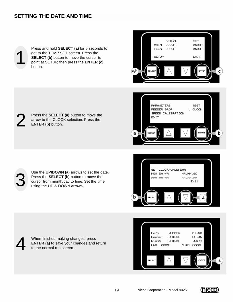
19
1SELECT ENTER
Press and hold SELECT (a) for 5 seconds toget to the TEMP SET screen. Press theSELECT (b) button to move the cursor topoint at SETUP, then press the ENTER (c)button.
SETTING THE DATE AND TIME
SELECT ENTER
SET CLOCK/CALENDAR
MON DA/YR HR.MN.SC
xxx xx/xx xx.xx.xx
Exit
2S C O
SELECT ENTER
Press the SELECT (a) button to move thearrow to the CLOCK selection. Press theENTER (b) button.
3Use the UP/DOWN (a) arrows to set the date.Press the SELECT (b) button to move thecursor from month/day to time. Set the timeusing the UP & DOWN arrows.
SELECT ENTER
Left WHOPPR 01:50
Center CHICKN 03:45
Right CHICKN 03:45
FLX XXXXF MAIN XXXXF4 When finished making changes, pressENTER (a) to save your changes and returnto the normal run screen.
a
a,b
a
b
a
ACTUAL SET
MAIN xxxxF 0500F
FLEX xxxxF 0500F
SETUP EXIT
c
PARAMETERS TEST
FEEDER DROP CLOCK
SPEED CALIBRATION
EXIT
→
b
→
Nieco Corporation - Model 9025
20
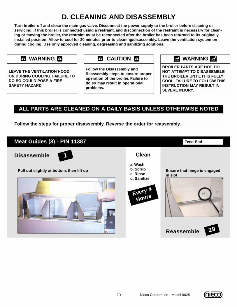
D. CLEANING AND DISASSEMBLYTurn broiler off and close the main gas valve. Disconnect the power supply to the broiler before cleaning orservicing. If this broiler is connected using a restraint, and disconnection of the restraint is necessary for clean-ing or moving the broiler, the restraint must be reconnected after the broiler has been returned to its originallyinstalled position. Allow to cool for 30 minutes prior to cleaning/disassembly. Leave the ventilation system onduring cooling. Use only approved cleaning, degreasing and sanitizing solutions.
ALL PARTS ARE CLEANED ON A DAILY BASIS UNLESS OTHERWISE NOTED
Follow the steps for proper disassembly. Reverse the order for reassembly.
Every 4
Hours
Feed EndMeat Guides (3) - P/N 11387
Reassemble
1Disassemble Clean
a. Wash b. Scrub c. Rinse d. Sanitize
Pull out slightly at bottom, then lift up
29
Ensure that hinge is engagedin slot
CAUTION
Follow the Disassembly andReassembly steps to ensure properoperation of the broiler. Failure todo so may result in operationalproblems.
WARNINGBROILER PARTS ARE HOT. DONOT ATTEMPT TO DISASSEMBLETHE BROILER UNTIL IT IS FULLYCOOL. FAILURE TO FOLLOW THISINSTRUCTION MAY RESULT INSEVERE INJURY.
WARNING
LEAVE THE VENTILATION HOODON DURING COOLING. FAILURE TODO SO COULD POSE A FIRESAFETY HAZARD.
Nieco Corporation - Model 9025
21
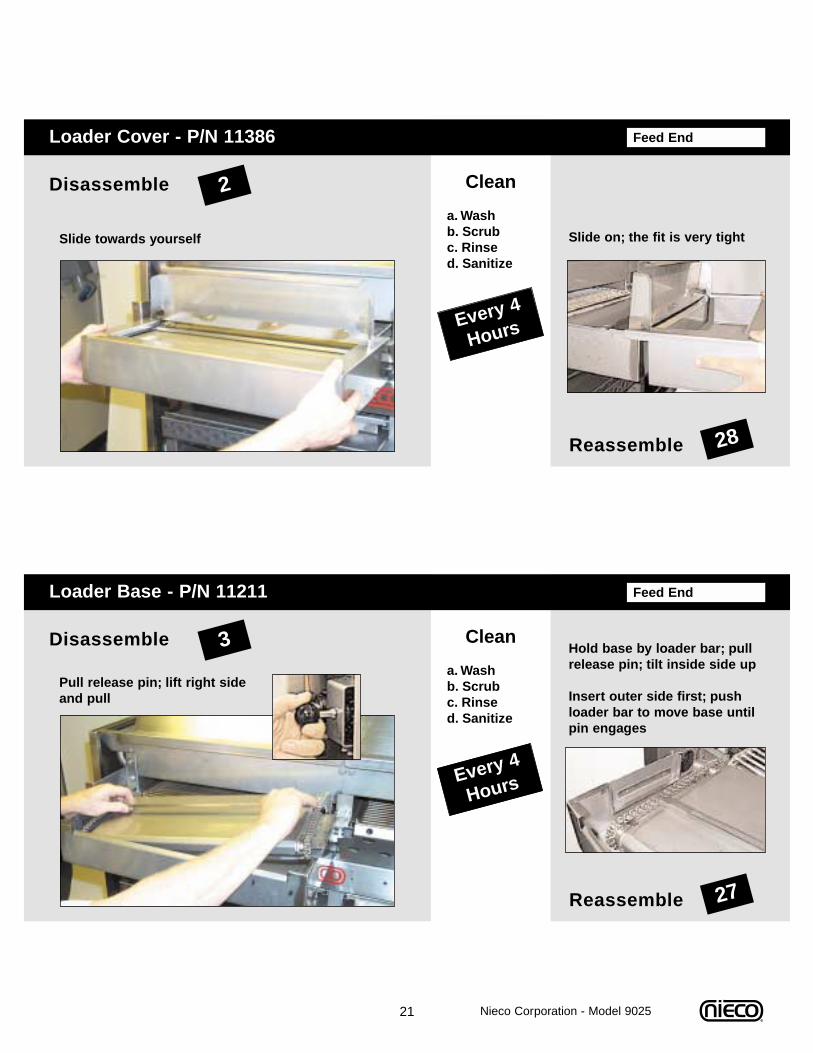
Feed EndLoader Base - P/N 11211
Reassemble
3Disassemble Clean
a. Wash b. Scrub c. Rinse d. Sanitize
Pull release pin; lift right sideand pull
27
Hold base by loader bar; pullrelease pin; tilt inside side up
Insert outer side first; pushloader bar to move base untilpin engages
Every 4
Hours
Feed EndLoader Cover - P/N 11386
Reassemble
2Disassemble Clean
a. Wash b. Scrub c. Rinse d. Sanitize
Slide towards yourself
28
Slide on; the fit is very tight
Every 4
Hours
Nieco Corporation - Model 9025
22
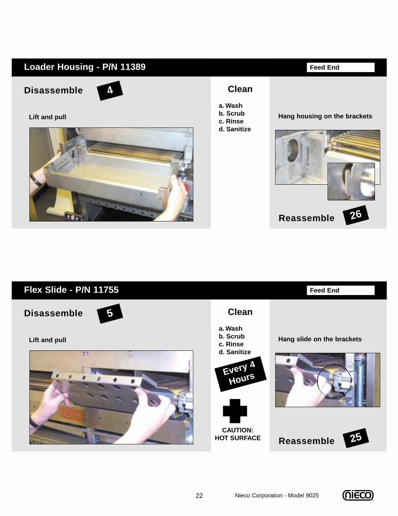
Feed EndFlex Slide - P/N 11755
Reassemble
5Disassemble Clean
a. Wash b. Scrub c. Rinse d. Sanitize
Lift and pull
25
Hang slide on the brackets
Every 4
Hours
Feed EndLoader Housing - P/N 11389
Reassemble
4Disassemble Clean
a. Wash b. Scrub c. Rinse d. Sanitize
Lift and pull
26
Hang housing on the brackets
Nieco Corporation - Model 9025
CAUTION:HOT SURFACE
23
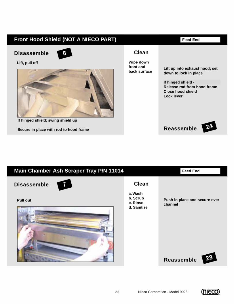
Feed EndMain Chamber Ash Scraper Tray P/N 11014
Reassemble
7Disassemble Clean
a. Wash b. Scrub c. Rinse d. Sanitize
Pull out
23
Push in place and secure overchannel
Feed EndFront Hood Shield (NOT A NIECO PART)
Reassemble
6Disassemble Clean
Wipe downfront andback surface
Lift, pull off
24If hinged shield; swing shield up
Secure in place with rod to hood frame
Lift up into exhaust hood; setdown to lock in place
If hinged shield - Release rod from hood frameClose hood shieldLock lever
Nieco Corporation - Model 9025
24
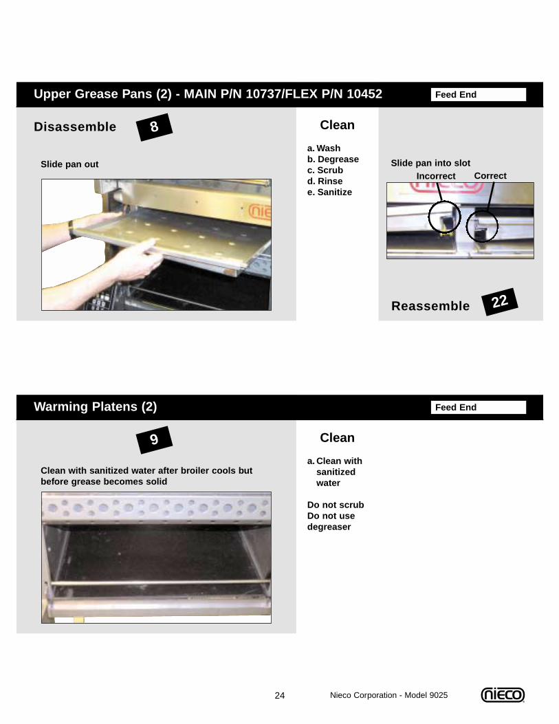
Feed EndWarming Platens (2)
9 Clean
a. Clean with sanitized water
Do not scrubDo not usedegreaser
Clean with sanitized water after broiler cools butbefore grease becomes solid
Feed EndUpper Grease Pans (2) - MAIN P/N 10737/FLEX P/N 10452
Reassemble
8Disassemble Clean
a. Wash b. Degreasec. Scrub d. Rinse e. Sanitize
Slide pan out
22
Slide pan into slotIncorrect Correct
Nieco Corporation - Model 9025
25
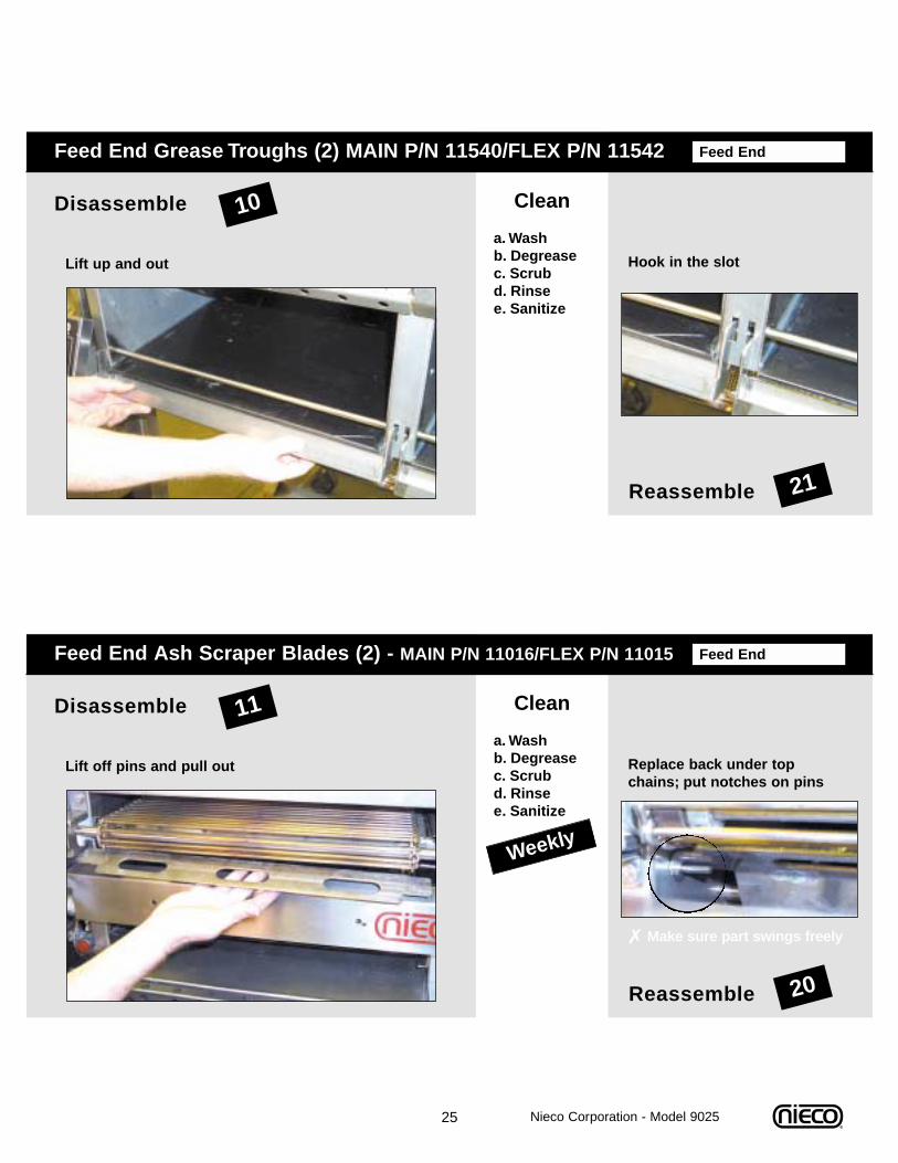
Feed EndFeed End Ash Scraper Blades (2) - MAIN P/N 11016/FLEX P/N 11015
Reassemble
11Disassemble Clean
a. Wash b. Degreasec. Scrub d. Rinse e. Sanitize
Lift off pins and pull out
20
Replace back under topchains; put notches on pins
Weekly
✗ Make sure part swings freely
Feed EndFeed End Grease Troughs (2) MAIN P/N 11540/FLEX P/N 11542
Reassemble
10Disassemble Clean
a. Wash b. Degreasec. Scrub d. Rinse e. Sanitize
Lift up and out
21
Hook in the slot
Nieco Corporation - Model 9025
26
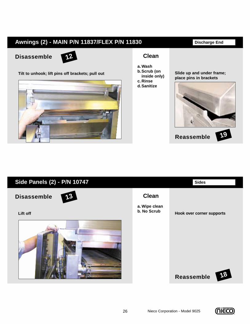
SidesSide Panels (2) - P/N 10747
Reassemble
13Disassemble Clean
a. Wipe cleanb. No ScrubLift off
18
Hook over corner supports
Discharge EndAwnings (2) - MAIN P/N 11837/FLEX P/N 11830
Reassemble
12Disassemble Clean
a. Washb.Scrub (on
inside only)c. Rinsed.Sanitize
Tilt to unhook; lift pins off brackets; pull out
19
Slide up and under frame;place pins in brackets
Nieco Corporation - Model 9025
27
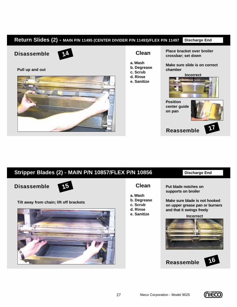
Discharge EndStripper Blades (2) - MAIN P/N 10857/FLEX P/N 10856
Reassemble
15Disassemble Clean
a. Wash b. Degreasec. Scrub d. Rinse e. Sanitize
Tilt away from chain; lift off brackets
16
Put blade notches on supports on broiler
Make sure blade is not hookedon upper grease pan or burnersand that it swings freely
Incorrect
Discharge EndReturn Slides (2) - MAIN P/N 11495 (CENTER DIVIDER P/N 11493)/FLEX P/N 11497
Reassemble
14Disassemble Clean
a. Wash b. Degreasec. Scrub d. Rinse e. Sanitize
Pull up and out
17
Place bracket over broilercrossbar; set down
Make sure slide is on correctchamber
Position center guideon pan
Incorrect
Nieco Corporation - Model 9025
28
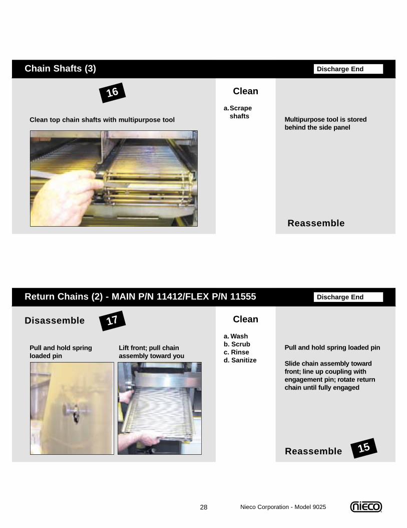
Discharge EndReturn Chains (2) - MAIN P/N 11412/FLEX P/N 11555
Reassemble
17Disassemble Clean
a. Wash b. Scrub c. Rinse d. Sanitize
Pull and hold spring loaded pin
15
Pull and hold spring loaded pin
Slide chain assembly towardfront; line up coupling withengagement pin; rotate returnchain until fully engaged
Lift front; pull chain assembly toward you
Reassemble
Multipurpose tool is storedbehind the side panel
Discharge EndChain Shafts (3)
16 Clean
a.Scrape shaftsClean top chain shafts with multipurpose tool
Nieco Corporation - Model 9025
29
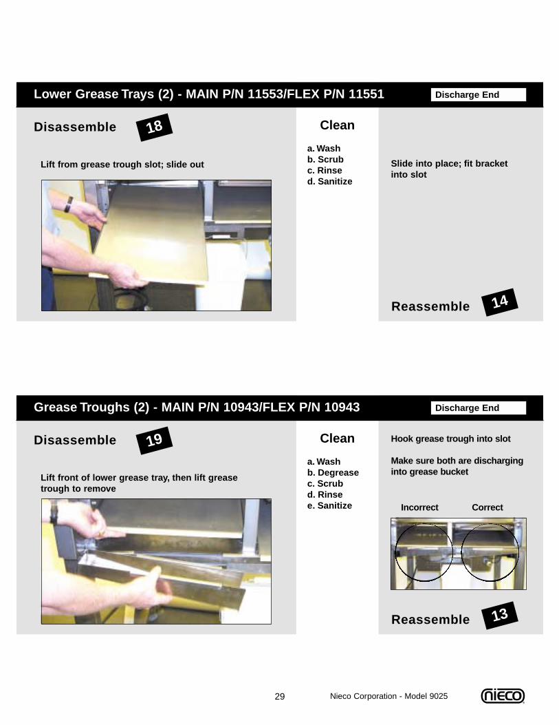
Discharge EndLower Grease Trays (2) - MAIN P/N 11553/FLEX P/N 11551
Reassemble
18Disassemble Clean
a. Wash b. Scrub c. Rinse d. Sanitize
Lift from grease trough slot; slide out
14
Slide into place; fit bracketinto slot
Discharge EndGrease Troughs (2) - MAIN P/N 10943/FLEX P/N 10943
Reassemble
19Disassemble Clean
a. Wash b. Degreasec. Scrub d. Rinse e. Sanitize
Lift front of lower grease tray, then lift greasetrough to remove
13
Hook grease trough into slot
Make sure both are discharginginto grease bucket
Incorrect Correct
Nieco Corporation - Model 9025
30
Weekly
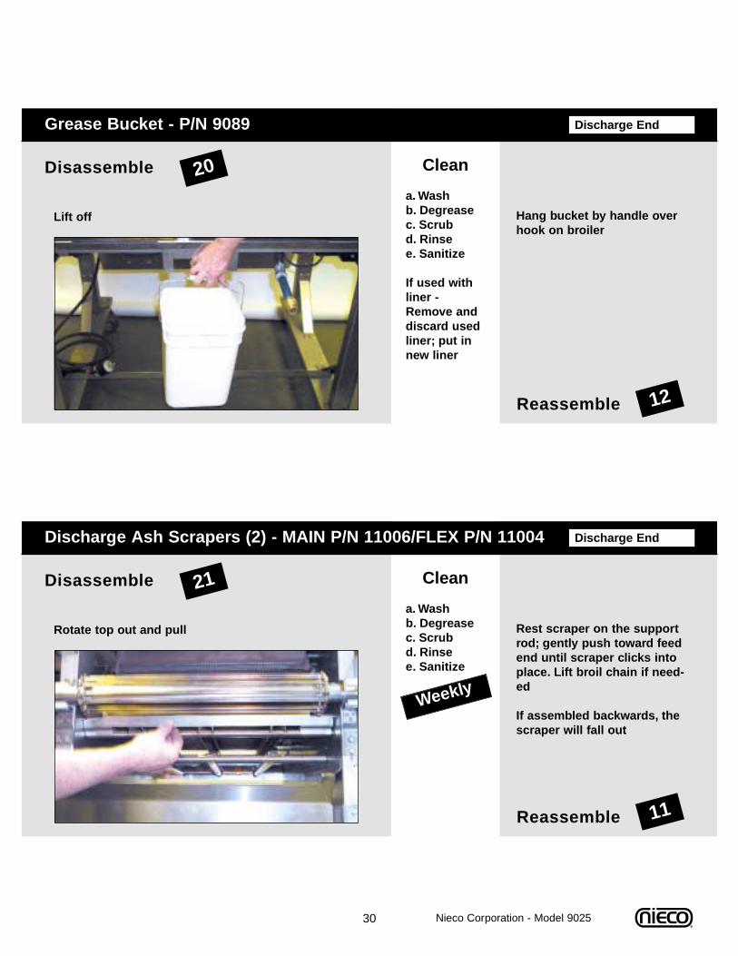
Discharge EndDischarge Ash Scrapers (2) - MAIN P/N 11006/FLEX P/N 11004
Reassemble
21Disassemble Clean
a. Wash b. Degreasec. Scrub d. Rinse e. Sanitize
Rotate top out and pull
11
Rest scraper on the supportrod; gently push toward feedend until scraper clicks intoplace. Lift broil chain if need-ed
If assembled backwards, thescraper will fall out
Discharge EndGrease Bucket - P/N 9089
Reassemble
20Disassemble Clean
a. Wash b. Degreasec. Scrub d. Rinse e. Sanitize
If used withliner -Remove anddiscard usedliner; put innew liner
Lift off
12
Hang bucket by handle overhook on broiler
Nieco Corporation - Model 9025
31
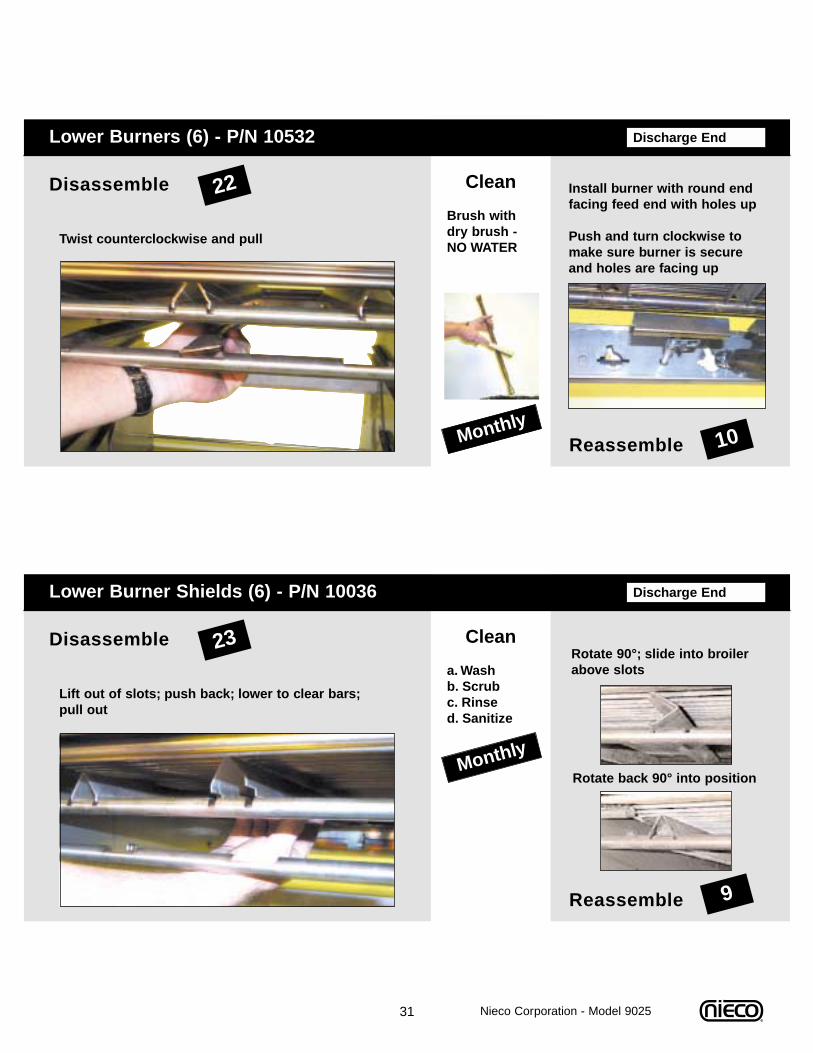
Monthly
Discharge EndLower Burner Shields (6) - P/N 10036
Reassemble
23Disassemble Clean
a. Washb. Scrubc. Rinsed. Sanitize
Lift out of slots; push back; lower to clear bars;pull out
9
Rotate 90°; slide into broilerabove slots
Rotate back 90° into position
Monthly
Discharge EndLower Burners (6) - P/N 10532
Reassemble
22Disassemble Clean
Brush withdry brush -NO WATER
Twist counterclockwise and pull
10
Install burner with round endfacing feed end with holes up
Push and turn clockwise tomake sure burner is secureand holes are facing up
Nieco Corporation - Model 9025
32
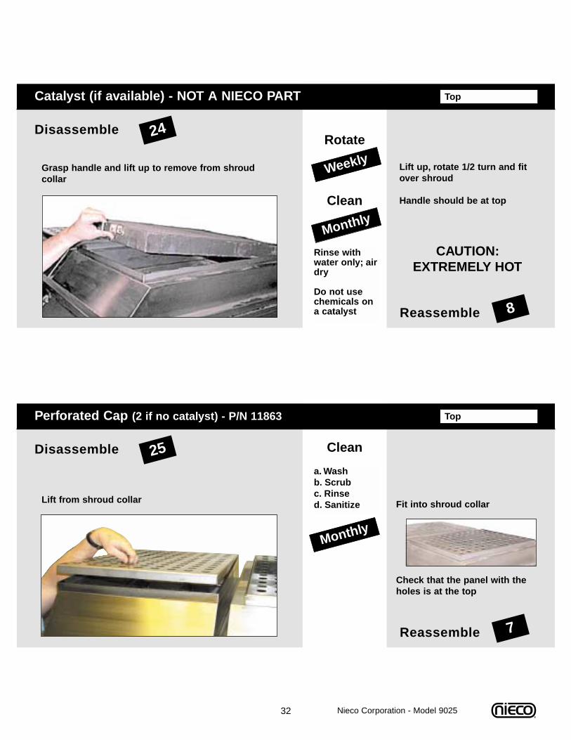
Monthly
TopCatalyst (if available) - NOT A NIECO PART
Reassemble
24Disassemble
Clean
Grasp handle and lift up to remove from shroudcollar
8
Lift up, rotate 1/2 turn and fitover shroud
Handle should be at top
Weekly
Rinse withwater only; airdry
Do not usechemicals ona catalyst
CAUTION:EXTREMELY HOT
Rotate
Nieco Corporation - Model 9025
Monthly
TopPerforated Cap (2 if no catalyst) - P/N 11863
Reassemble
25Disassemble Clean
a. Washb. Scrub c. Rinsed. SanitizeLift from shroud collar
7
Fit into shroud collar
Check that the panel with theholes is at the top
33
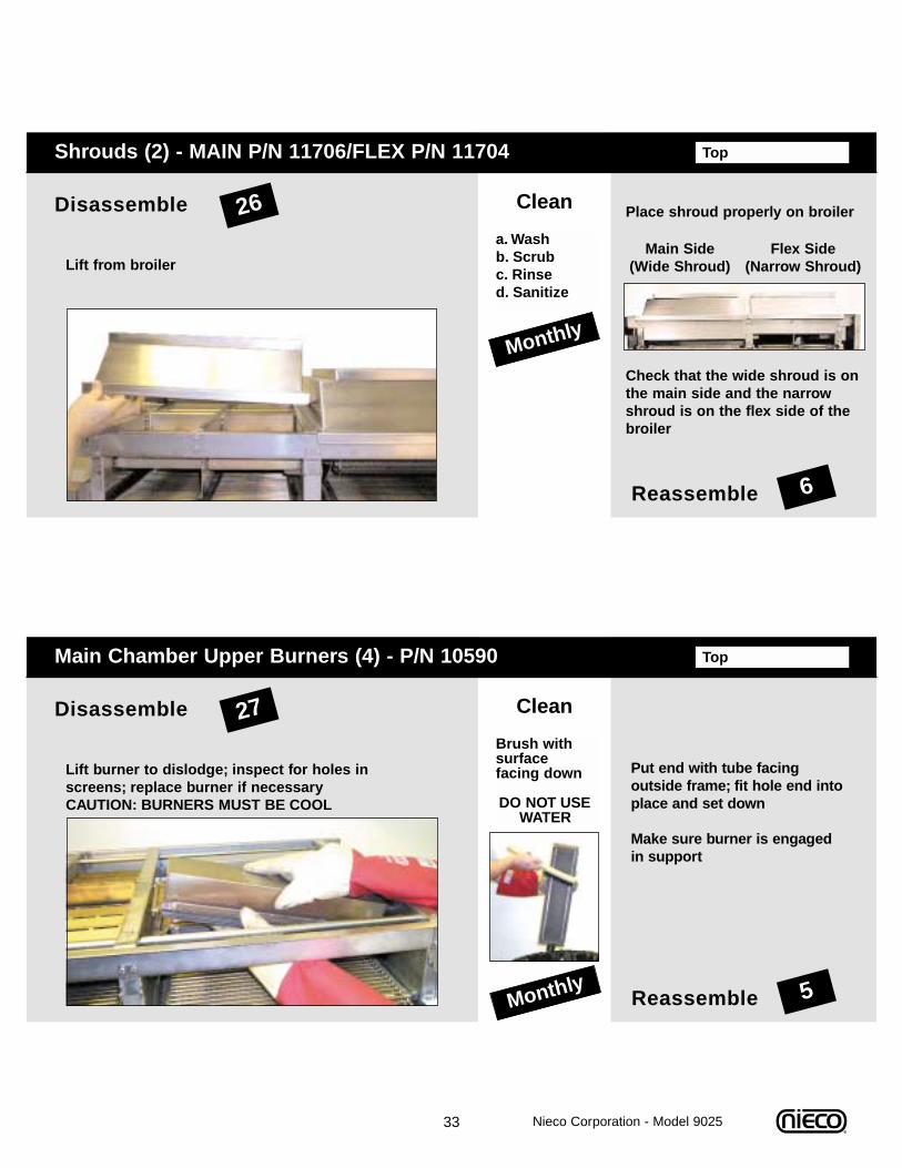
Monthly
TopMain Chamber Upper Burners (4) - P/N 10590
Reassemble
27Disassemble Clean
Brush withsurface facing down
DO NOT USEWATER
Lift burner to dislodge; inspect for holes inscreens; replace burner if necessaryCAUTION: BURNERS MUST BE COOL
5
Put end with tube facing outside frame; fit hole end intoplace and set down
Make sure burner is engagedin support
Nieco Corporation - Model 9025
Monthly
TopShrouds (2) - MAIN P/N 11706/FLEX P/N 11704
Reassemble
26Disassemble Clean
a. Washb. Scrub c. Rinsed. Sanitize
Lift from broiler
6
Place shroud properly on broiler
Check that the wide shroud is onthe main side and the narrowshroud is on the flex side of thebroiler
Main Side(Wide Shroud)
Flex Side(Narrow Shroud)
34
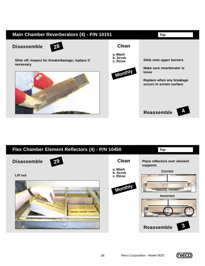
Monthly
TopFlex Chamber Element Reflectors (4) - P/N 10450
Reassemble
29Disassemble Clean
a. Washb. Scrubc. RinseLift out
3
Place reflectors over elementsupports
Correct
Incorrect
Monthly
TopMain Chamber Reverberators (4) - P/N 10151
Reassemble
28Disassemble Clean
a. Washb. Scrubc. RinseSlide off; inspect for breaks/damage; replace if
necessary
4
Slide onto upper burners
Make sure reverberator isloose
Replace when any breakageoccurs in screen surface
Nieco Corporation - Model 9025
35
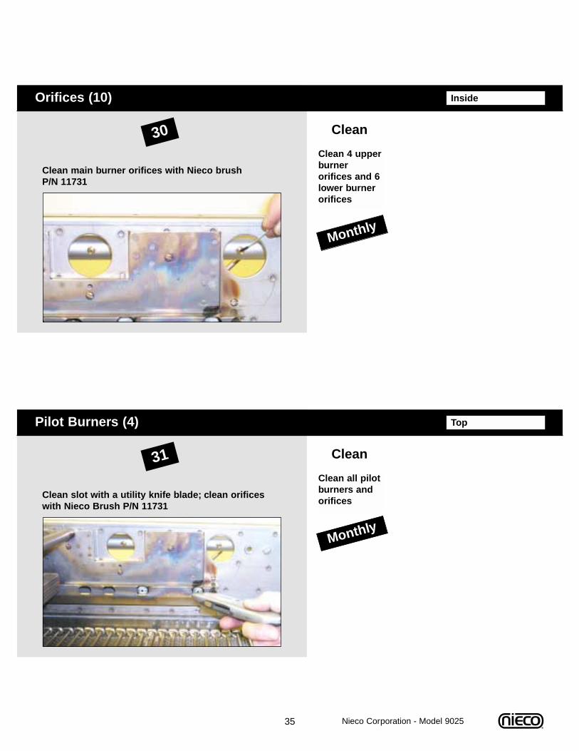
Monthly
TopPilot Burners (4)
31 Clean
Clean all pilotburners andorifices
Clean slot with a utility knife blade; clean orificeswith Nieco Brush P/N 11731
Monthly
InsideOrifices (10)
30 Clean
Clean 4 upperburner orifices and 6lower burnerorifices
Clean main burner orifices with Nieco brush P/N 11731
Nieco Corporation - Model 9025
36 Nieco Corporation - Model 9025
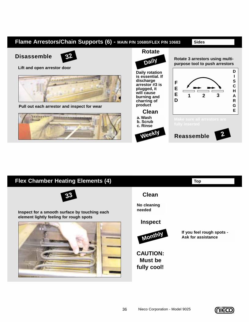
Monthly
TopFlex Chamber Heating Elements (4)
33 Clean
No cleaningneededInspect for a smooth surface by touching each
element lightly feeling for rough spotsInspect
CAUTION:Must be
fully cool!
If you feel rough spots - Ask for assistance
SidesFlame Arrestors/Chain Supports (6) - MAIN P/N 10680/FLEX P/N 10683
Reassemble
32Disassemble
Cleana. Washb. Scrubc. Rinse
Lift and open arrestor door
2
Rotate 3 arrestors using multi-purpose tool to push arrestors
Pull out each arrestor and inspect for wear
1 2 3
FEED
DISCHARGE
Make sure all arrestors arefully inserted
Weekly
Daily rotationis essential. Ifdischargearrestor #3 isplugged, itwill causeburning andcharring ofproduct
Rotate
Daily
37
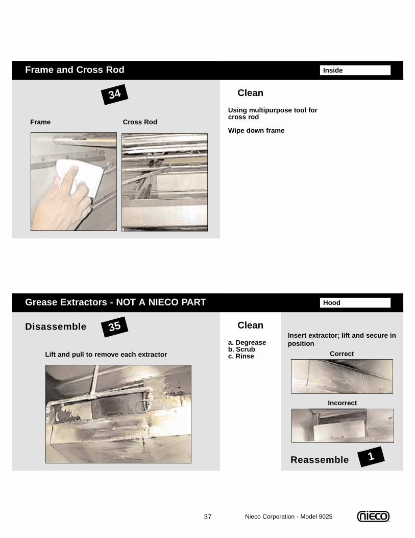
HoodGrease Extractors - NOT A NIECO PART
Reassemble
35Disassemble Clean
a. Degreaseb. Scrubc. RinseLift and pull to remove each extractor
1
Insert extractor; lift and secure inposition
Correct
Incorrect
InsideFrame and Cross Rod
34 Clean
Using multipurpose tool forcross rod
Wipe down frameFrame Cross Rod
Nieco Corporation - Model 9025
38 Nieco Corporation - Model 9025
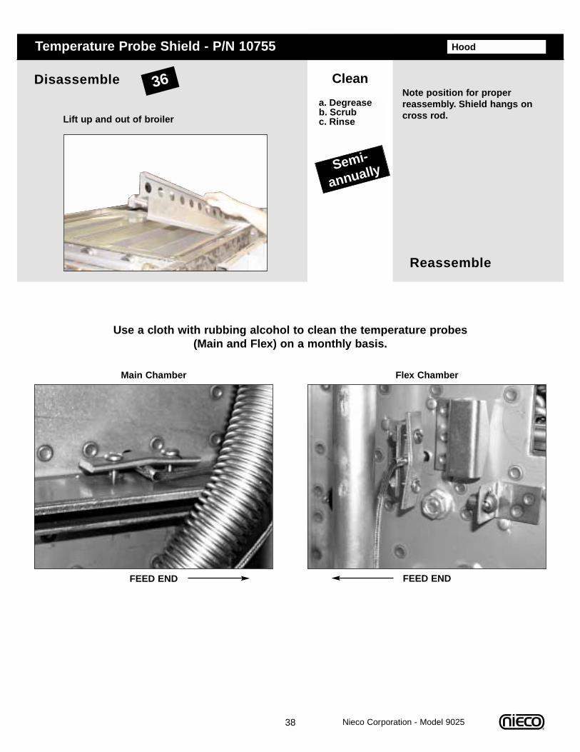
HoodTemperature Probe Shield - P/N 10755
Reassemble
Disassemble Clean
a. Degreaseb. Scrubc. RinseLift up and out of broiler
Note position for properreassembly. Shield hangs oncross rod.
Semi-
annually
Use a cloth with rubbing alcohol to clean the temperature probes (Main and Flex) on a monthly basis.
Main Chamber
FEED END
Flex Chamber
FEED END
36

E. TROUBLESHOOTING
Problem Solution
Pilots not lighting ❏ Check that broiler is plugged in, gas valve is open and broiler is turned on
❏ The 5-minute time limit was exceeded - press the timer reset button
❏ Manually light if it is not a timer problem❏ Check for ignition❏ Check for clogged pilot
Main burners not lighting
❏ Check for gas pressure, if there is pressure, use the manual lighting procedure
❏ If no gas pressure, call for service❏ Check for proper burner installation❏ Check for plugged burner orifices❏ Check for plugged pilot burner
Pilot not staying lit ❏ Hold in red pilot button longer ❏ Call for service as red pilot button or
thermocouple may need replacing
Broil chain jams ❏ Procedure to correct:__ Push reset button on keypad once to
reverse chain__ Push reset button a second time to run
chain forwardIf chain jams again, check:__ Arrestors for proper placement (Make
sure flex chamber arrestors are under both chains)
__ For sag in the chain with arrestors in place (Chain may need a link removed)
__ For an obstruction
Return chains notmoving
❏ Verify that return chains have correct side upwith drive shaft coupling lined up with engagement pin
❏ Check for sag in the return chain (May need to have a link removed)
39
Always verify that the broiler is properly assembled, the hood is on, gas valve open and broiler is plugged in.
Nieco Corporation - Model 9025
40
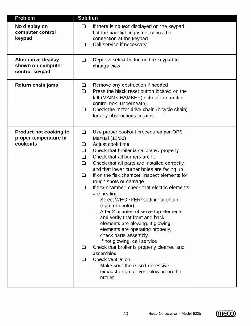
Return chain jams ❏ Remove any obstruction if needed❏ Press the black reset button located on the
left (MAIN CHAMBER) side of the broiler control box (underneath).
❏ Check the motor drive chain (bicycle chain) for any obstructions or jams
Product not cooking toproper temperature incookouts
❏ Use proper cookout procedures per OPSManual (12/00)
❏ Adjust cook time ❏ Check that broiler is calibrated properly❏ Check that all burners are lit❏ Check that all parts are installed correctly,
and that lower burner holes are facing up❏ If on the flex chamber, inspect elements for
rough spots or damage❏ If flex chamber; check that electric elements
are heating:__ Select WHOPPER® setting for chain
(right or center)__ After 2 minutes observe top elements
and verify that front and back elements are glowing. If glowing, elements are operating properly, check parts assembly.If not glowing, call service
❏ Check that broiler is properly cleaned and assembled
❏ Check ventilation__ Make sure there isn’t excessive
exhaust or an air vent blowing on the broiler
Problem Solution
Nieco Corporation - Model 9025
No display on computer control keypad
❏ If there is no text displayed on the keypad but the backlighting is on, check the connection at the keypad
❏ Call service if necessary
Alternative displayshown on computercontrol keypad
❏ Depress select button on the keypad to change view
41
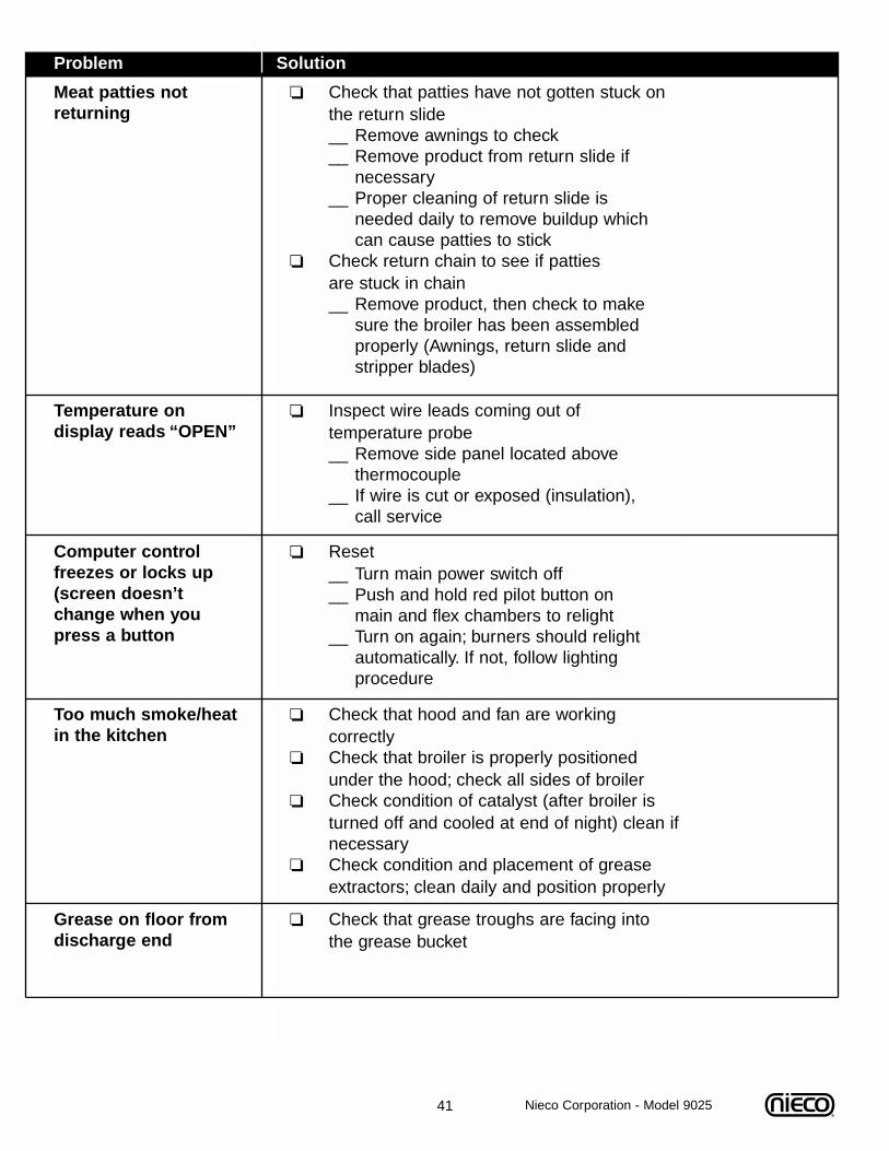
Meat patties notreturning
❏ Check that patties have not gotten stuck on the return slide__ Remove awnings to check__ Remove product from return slide if
necessary__ Proper cleaning of return slide is
needed daily to remove buildup which can cause patties to stick
❏ Check return chain to see if patties are stuck in chain__ Remove product, then check to make
sure the broiler has been assembled properly (Awnings, return slide and stripper blades)
Temperature on display reads “OPEN”
❏ Inspect wire leads coming out of temperature probe__ Remove side panel located above
thermocouple__ If wire is cut or exposed (insulation),
call service
Computer controlfreezes or locks up(screen doesn’tchange when youpress a button
❏ Reset__ Turn main power switch off__ Push and hold red pilot button on
main and flex chambers to relight__ Turn on again; burners should relight
automatically. If not, follow lighting procedure
Too much smoke/heatin the kitchen
❏ Check that hood and fan are working correctly
❏ Check that broiler is properly positioned under the hood; check all sides of broiler
❏ Check condition of catalyst (after broiler is turned off and cooled at end of night) clean ifnecessary
❏ Check condition and placement of grease extractors; clean daily and position properly
Grease on floor fromdischarge end
❏ Check that grease troughs are facing into the grease bucket
Problem Solution
Nieco Corporation - Model 9025
42
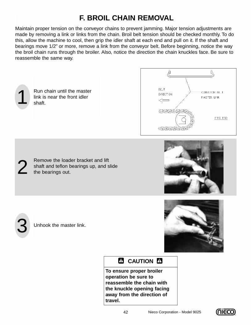
F. BROIL CHAIN REMOVAL
1 Run chain until the masterlink is near the front idlershaft.
2Remove the loader bracket and liftshaft and teflon bearings up, and slidethe bearings out.
3 Unhook the master link.
Maintain proper tension on the conveyor chains to prevent jamming. Major tension adjustments aremade by removing a link or links from the chain. Broil belt tension should be checked monthly. To dothis, allow the machine to cool, then grip the idler shaft at each end and pull on it. If the shaft andbearings move 1/2” or more, remove a link from the conveyor belt. Before beginning, notice the waythe broil chain runs through the broiler. Also, notice the direction the chain knuckles face. Be sure toreassemble the same way.
CAUTION
To ensure proper broileroperation be sure toreassemble the chain withthe knuckle opening facingaway from the direction oftravel.
Nieco Corporation - Model 9025
43
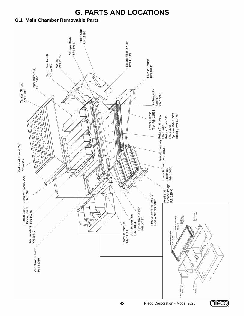
G. PARTS AND LOCATIONS G.1 Main Chamber Removable Parts
Per
fora
ted
Shr
oud
Cap
P/N
118
63A
rres
tor
Acc
ess
Doo
rP
/N 1
0925
Tem
pera
ture
P
robe
Shi
eld
P/N
107
55S
ide
Pan
el (
2)P
/N 1
0747
Ash
Scr
aper
Bla
deP
/N 1
1016
Low
er B
urne
r (3
)P
/N 1
2193
Ash
Scr
aper
Tra
yP
/N 1
1014
Upp
er G
reas
e P
anP
/N 1
0737
Pro
duct
Hol
ding
Pan
s (3
)N
OT
A N
IEC
O P
AR
T
Fee
d E
nd
Gre
ase
Trou
ghP
/N 1
1540
Low
er B
urne
r S
hiel
d (3
)P
/N 1
0036
Rev
erbe
rato
r (4
)P
/N 1
0151
Ret
urn
Cha
in A
ssy
P/N
114
12R
etur
n C
hain
19"
P/N
115
72S
proc
ket P
/N 1
1565
Bea
ring
P/N
114
78
Low
er G
reas
e Tr
ay P
/N 1
1553
Dis
char
ge A
sh
Scr
aper
P/N
110
06
Gre
ase
Trou
ghP
/N 1
0943R
etur
n S
lide
Div
ider
P/N
114
93
Ret
urn
Slid
eP
/N 1
1495
Str
ippe
r B
lade
P/N
108
57
Aw
ning
P/N
118
37
Fla
me
Arr
esto
r (3
)P
/N 1
0680
Upp
er B
urne
r (4
)P
/N 1
0590
Cat
alys
t Shr
oud
P/N
117
06
Nieco Corporation - Model 9025
Fee
der
Driv
e H
ubP
/N 1
1194
Pus
h B
ar A
ssem
bly
P/N
112
11 Bar
Onl
yP
/N 1
1378
Lane
Div
ider
(3)
P/N
113
87
Cov
erP
/N 1
2122
Enc
losu
reP
/N 1
1389
On
Bro
iler
(not
sho
wn)
Eng
agem
ent P
in
P/N
111
94B
lack
Kno
bP
/N 1
1608
Spr
ocke
t, 13
T 1
/2"
Bor
eP
/N 6
007
Spr
ocke
t, 13
T, 5
/8"
Bor
eP
/N 6
040
44
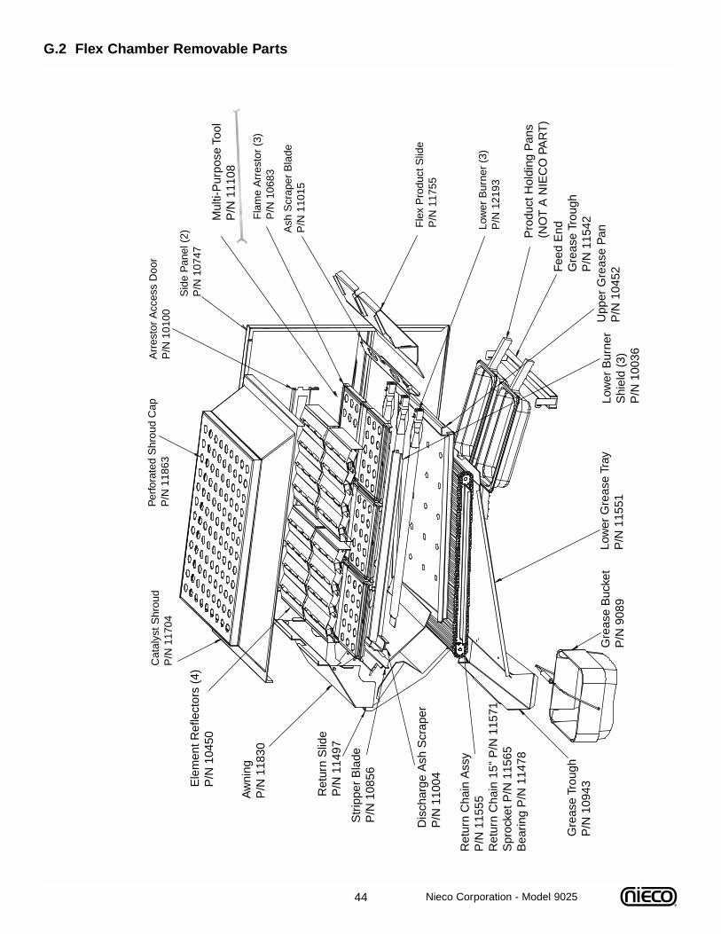
G.2 Flex Chamber Removable Parts
Cat
alys
t Shr
oud
P/N
117
04
Ele
men
t Ref
lect
ors
(4)
P/N
104
50
Aw
ning
P/N
118
30
Ret
urn
Slid
eP
/N 1
1497
Str
ippe
r B
lade
P/N
108
56
Dis
char
ge A
sh S
crap
erP
/N 1
1004
Ret
urn
Cha
in A
ssy
P/N
115
55R
etur
n C
hain
15"
P/N
115
71S
proc
ket P
/N 1
1565
Bea
ring
P/N
114
78
Gre
ase
Trou
ghP
/N 1
0943
Gre
ase
Buc
ket
P/N
908
9Lo
wer
Gre
ase
Tray
P/N
115
51Lo
wer
Bur
ner
Shi
eld
(3)
P/N
100
36
Upp
er G
reas
e P
anP
/N 1
0452
Fee
d E
ndG
reas
e Tr
ough
P/N
115
42
Pro
duct
Hol
ding
Pan
s(N
OT
A N
IEC
O P
AR
T)
Low
er B
urne
r (3
)P
/N 1
2193
Fle
x P
rodu
ct S
lide
P/N
117
55
Ash
Scr
aper
Bla
deP
/N 1
1015
Fla
me
Arr
esto
r (3
)P
/N 1
0683
Sid
e P
anel
(2)
P/N
107
47
Arr
esto
r A
cces
s D
oor
P/N
101
00P
erfo
rate
d S
hrou
d C
apP
/N 1
1863
Mul
ti-P
urpo
se T
ool
P/N
111
08
Nieco Corporation - Model 9025
45 Nieco Corporation - Model 9025
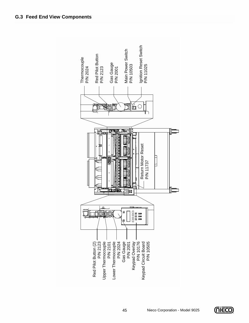
G.3 Feed End View Components
The
rmoc
oupl
eP
/N 2
024
Red
Pilo
t But
ton
P/N
212
3
Gas
Gau
geP
/N 2
001
Mai
n P
ower
Sw
itch
P/N
105
03
Igni
tion
Res
et S
witc
hP
/N 1
1025
Red
Pilo
t But
ton
(2)
P/N
212
3U
pper
The
rmoc
oupl
eP
/N 2
101
Low
er T
herm
ocou
ple
P/N
202
4G
as G
auge
P/N
200
1K
eypa
d O
verla
yP
/N 1
0176
Key
pad
Circ
uit B
oard
P/N
105
05
Ret
urn
Mot
or R
eset
P/N
117
37
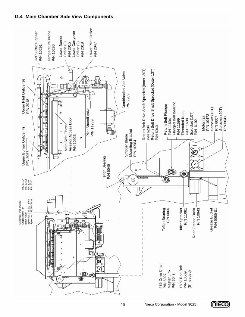
46 Nieco Corporation - Model 9025
G.4 Main Chamber Side View Components
Com
bina
tion
Gas
Val
veP
/N 2
209
Pilo
t Shu
toff
Val
veP
/N 1
1739
Low
er B
urne
rO
rific
e (3
)P
/N 2
015
Low
er C
arry
over
Orif
ice
(2)
P/N
201
8
Low
er P
ilot O
rific
eP
/N 2
047
Hot
Sur
face
Igni
ter
P/N
102
91
Tem
pera
ture
Pro
beP
/N 1
0290
Upp
er B
urne
r O
rific
e (4
)U
pper
Pilo
t Orif
ice
(9)
P/N
206
7P
/N 2
018
Ret
urn
Bel
t Driv
e S
haft
Spr
ocke
t (In
ner
20T
)P
/N 6
204
Ret
urn
Bel
t Driv
e S
haft
Spr
ocke
t (O
uter
13T
)P
/N 6
040
R
etur
n B
elt P
lung
er
P
/N 1
1604
F
lang
ed B
all B
earin
g
P/N
115
99
Thr
eade
d K
nob
P
/N 1
1608
S
proc
ket (
10T
)
P/N
610
2
Teflo
n B
earin
gP
/N 6
066
Idle
r S
proc
ket
P/N
110
81
Rea
r G
reas
e D
rain
P/N
109
43
Gre
ase
Buc
ket
P/N
908
9-01
Mot
or (
2)P
/N 1
0473
Spr
ocke
t (13
T)
P/N
600
7S
proc
ket (
20T
)P
/N 6
041
Mai
n S
ide
Fla
me
Arr
esto
r A
cces
s D
oor
P/N
109
25
Str
ippe
r B
lade
Mou
ntin
g B
rack
etP
/N 1
0984
#35
Driv
e C
hain
P/N
602
7M
aste
r Li
nk
P/N
604
8
Teflo
n B
earin
gP
/N 6
046
18.5
" R
od B
elt
P/N
105
09(6
' nee
ded)
On
Bro
iler
(not
sho
wn)
Eng
agem
ent P
in
P/N
111
94B
lack
Kno
bP
/N 1
1608
Spr
ocke
t, 13
T 1
/2"
Bor
eP
/N 6
007
Spr
ocke
t, 13
T, 5
/8"
Bor
eP
/N 6
040
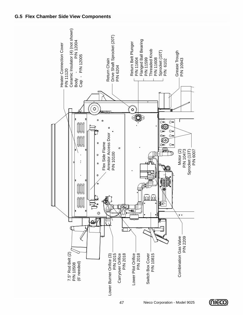
47 Nieco Corporation - Model 9025
G.5 Flex Chamber Side View Components
Low
er B
urne
r O
rific
e (3
)P
/N 2
015
Car
ryov
er O
rific
eP
/N 2
018
Low
er P
ilot O
rific
eP
/N 2
018
Sw
itch
Box
Cov
erP
/N 1
0815
Fle
x S
ide
Fla
me
Arr
esto
r A
cces
s D
oor
P/N
101
00R
etur
n C
hain
D
rive
Sha
ft S
proc
ket (
20T
)P
/N 6
204
R
etur
n B
elt P
lung
er
P
/N 1
1604
F
lang
ed B
all B
earin
g
P/N
115
99
Thr
eade
d K
nob
P
/N 1
1608
S
proc
ket (
10T
)
P/N
610
2
Mot
or (
2)P
/N 1
0473
Spr
ocke
t (13
T)
P/N
600
7
Gre
ase
Trou
ghP
/N 1
0943
Hea
ter
Con
nect
ion
Cov
erP
/N 1
1120
Cer
amic
Insu
lato
r (4
) (n
ot s
how
n)B
ody
- P
/N 1
2004
Cap
-
P/N
120
05
Com
bina
tion
Gas
Val
veP
/N 2
209
7.5"
Rod
Bel
t (2)
P/N
105
08(6
' nee
ded)
48 Nieco Corporation - Model 9025
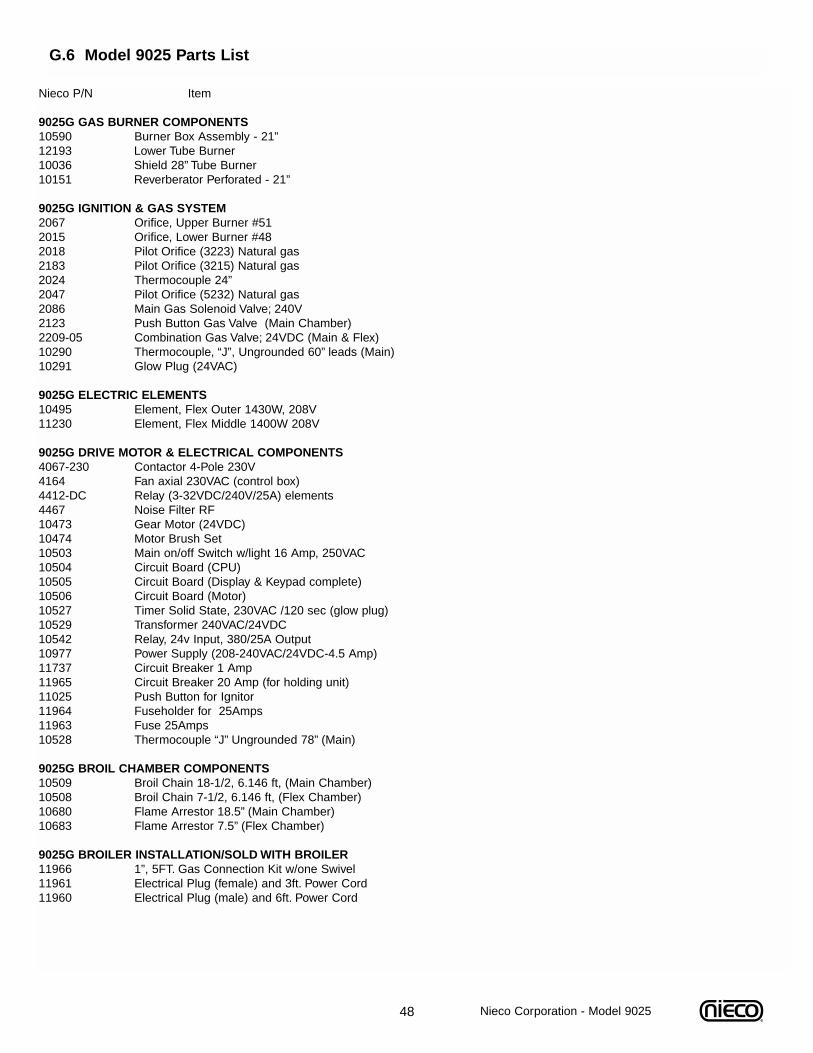
G.6 Model 9025 Parts List
Nieco P/N Item
9025G GAS BURNER COMPONENTS10590 Burner Box Assembly - 21”12193 Lower Tube Burner10036 Shield 28” Tube Burner10151 Reverberator Perforated - 21”
9025G IGNITION & GAS SYSTEM2067 Orifice, Upper Burner #512015 Orifice, Lower Burner #482018 Pilot Orifice (3223) Natural gas2183 Pilot Orifice (3215) Natural gas2024 Thermocouple 24”2047 Pilot Orifice (5232) Natural gas2086 Main Gas Solenoid Valve; 240V2123 Push Button Gas Valve (Main Chamber)2209-05 Combination Gas Valve; 24VDC (Main & Flex)10290 Thermocouple, “J”, Ungrounded 60” leads (Main)10291 Glow Plug (24VAC)
9025G ELECTRIC ELEMENTS10495 Element, Flex Outer 1430W, 208V11230 Element, Flex Middle 1400W 208V
9025G DRIVE MOTOR & ELECTRICAL COMPONENTS4067-230 Contactor 4-Pole 230V4164 Fan axial 230VAC (control box)4412-DC Relay (3-32VDC/240V/25A) elements4467 Noise Filter RF10473 Gear Motor (24VDC)10474 Motor Brush Set10503 Main on/off Switch w/light 16 Amp, 250VAC10504 Circuit Board (CPU)10505 Circuit Board (Display & Keypad complete)10506 Circuit Board (Motor)10527 Timer Solid State, 230VAC /120 sec (glow plug)10529 Transformer 240VAC/24VDC10542 Relay, 24v Input, 380/25A Output10977 Power Supply (208-240VAC/24VDC-4.5 Amp)11737 Circuit Breaker 1 Amp11965 Circuit Breaker 20 Amp (for holding unit)11025 Push Button for Ignitor11964 Fuseholder for 25Amps11963 Fuse 25Amps10528 Thermocouple “J” Ungrounded 78” (Main)
9025G BROIL CHAMBER COMPONENTS10509 Broil Chain 18-1/2, 6.146 ft, (Main Chamber)10508 Broil Chain 7-1/2, 6.146 ft, (Flex Chamber)10680 Flame Arrestor 18.5” (Main Chamber)10683 Flame Arrestor 7.5” (Flex Chamber)
9025G BROILER INSTALLATION/SOLD WITH BROILER11966 1”, 5FT. Gas Connection Kit w/one Swivel11961 Electrical Plug (female) and 3ft. Power Cord11960 Electrical Plug (male) and 6ft. Power Cord
49
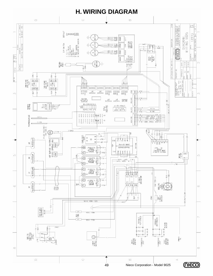
H. WIRING DIAGRAM
Nieco Corporation - Model 9025
50
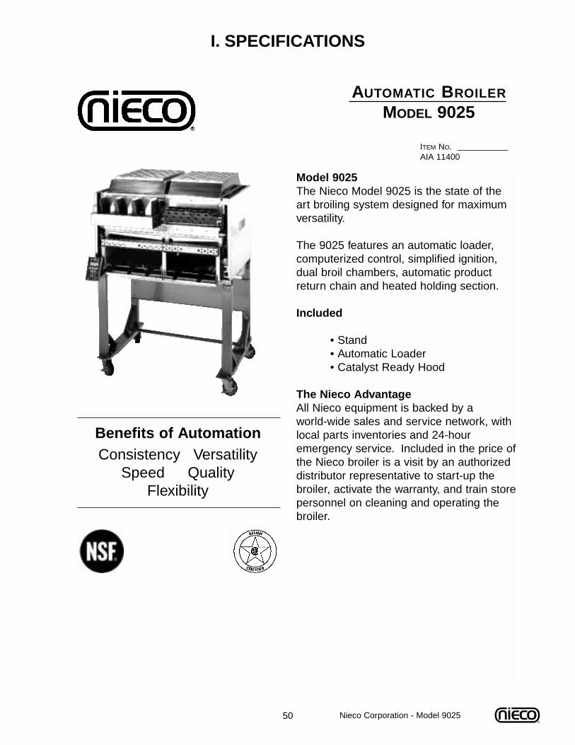
I. SPECIFICATIONS
Benefits of AutomationConsistency Versatility
Speed QualityFlexibility
AUTOMATIC BROILER
MODEL 9025
ITEM NO.AIA 11400
Model 9025The Nieco Model 9025 is the state of theart broiling system designed for maximum versatility.
The 9025 features an automatic loader,computerized control, simplified ignition,dual broil chambers, automatic productreturn chain and heated holding section.
Included
• Stand• Automatic Loader• Catalyst Ready Hood
The Nieco AdvantageAll Nieco equipment is backed by a world-wide sales and service network, withlocal parts inventories and 24-hour emergency service. Included in the price ofthe Nieco broiler is a visit by an authorizeddistributor representative to start-up thebroiler, activate the warranty, and train storepersonnel on cleaning and operating thebroiler.
Nieco Corporation - Model 9025
51
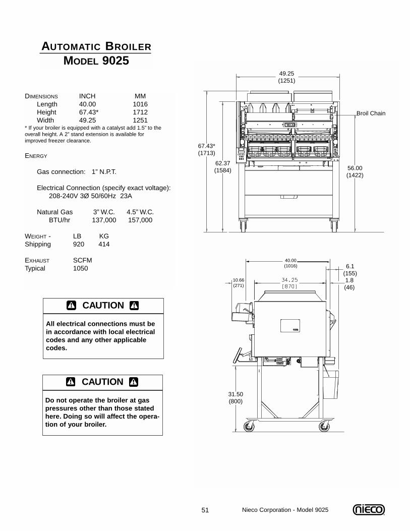
DIMENSIONS INCH MMLength 40.00 1016Height 67.43* 1712Width 49.25 1251
* If your broiler is equipped with a catalyst add 1.5” to the overall height. A 2” stand extension is available for improved freezer clearance.
ENERGY
Gas connection: 1” N.P.T.
Electrical Connection (specify exact voltage):208-240V 3Ø 50/60Hz 23A
Natural Gas 3” W.C. 4.5” W.C.BTU/hr 137,000 157,000
WEIGHT - LB KGShipping 920 414
EXHAUST SCFMTypical 1050
AUTOMATIC BROILER
MODEL 9025
67.43*(1713)
62.37(1584) 56.00
(1422)
Broil Chain
49.25(1251)
6.1(155)1.8(46)
31.50(800)
10.66(271)
40.00(1016)
CAUTION
All electrical connections must bein accordance with local electricalcodes and any other applicablecodes.
CAUTION
Do not operate the broiler at gaspressures other than those statedhere. Doing so will affect the opera-tion of your broiler.
Nieco Corporation - Model 9025
52
J. WARRANTY INFORMATION
Nieco Corporation - Model 9025
1. Seller guarantees new Nieco automatic infrared equipment against defectiveworkmanship and materials for a period of twelve months from the date of installationwith the exception of the inconel radiant surfaces, protective shields, reverberators, andelectric broiling elements which are guaranteed for a period of six months from date ofinstallation. The results of ordinary wear, neglect or misuse, accident or excessivedeterioration from any cause are not considered defects. Seller’s liability for defectiveparts is f.o.b. the factory where originally manufactured.
2. We guarantee the correct mechanical operation of the equipment at time ofinstallation, however, we make no warranty expressed or implied of cooking effector of exact capacity as subjective judgements and product variations will alterevaluation of such performance.
3. Our warranty includes field labor for the replacement of guaranteed parts by anauthorized Nieco Distributor for a period of 90 days after start-up. This labor servicewarranty is provided in all areas covered by an Authorized Nieco Distributor.
4. We specifically do not warrant any production or product losses or otherconsequential damages which may occur as a result of equipment malfunction orfailure, whether the cause of malfunction or failure is otherwise covered by ourwarranty or not.
5. Seller makes no other representations or warranties of any kind, express or implied,relating to the material and equipment herein described, not expressly set forth in theagreement or any written modification. Any and all implied warranties of suitability orfitness for a particular purpose which exceed the above obligation are hereby disclaimedby Seller and excluded. Seller will not be liable for any consequential damages, loss orexpense arising in connection with the use of, or the inability to use its goods for anypurpose whatever. In any event, any liability of the Seller shall be limited to the purchaseprice of the materials and equipment herein described. Guarantee valid only if guaranteeregistration card is filled out and mailed to manufacturer within fourteen (14) days aftermachine is installed.
IMPORTANT
The Nieco Corporation reserves the right to change specifications and product design in accordance with the general terms and conditions outlined in the BURGER KING®/Vendor
agreement. .Such revisions do not entitle the buyer to corresponding changes, improvements,additions or replacements for previously purchased equipment.

Nieco Corporation • 7950 Cameron Drive • Windsor, CA 95492 • (707) 284-7100 Office • (707) 284-7430 FaxReorder # 9999-25 3/02 www.nieco.com • e-mail: [email protected] Printed in the USA © 2002 Nieco Corporation