Embed Size (px)
Citation preview
5100
609637Rev. 00 (01-00)
Model No.: 609454 – 230V609677 – 240V EMC
FAX: 1–800–678–4240 CUSTOMER SERVICE: 1–800-982-7658
TENNANT COMPANY Commercial Products12875 RANSOM STREET HOLLAND MI 49424 U.S.A.
Operator and Parts Manual
Automatic Electric Scrubber
OPERATION
2 Tennant 5100 (01–00)
This manual is furnished with each new model. Itprovides necessary operation, maintenanceinstructions and an illustrated parts list.
Read this manual completely and understand themachine before operating or servicing.
When ordering replacement parts use the parts listssection in this manual. Before ordering parts orsupplies, be sure to have your machine model numberand serial number handy. Parts and supplies may beordered by phone or mail from any authorized ServiceCenter or Distributor.
This machine will provide excellent service. However,the best results will be obtained at minimum costs if:
� The machine is operated with reasonable care.
� The machine is maintained regularly - per themachine maintenance instructions provided.
� The machine is maintained with manufacturersupplied or equivalent parts.
MACHINE DATA
Please fill out at time of installation for future reference.
Model No.-
Install. Date -
Serial No.-
Copyright�2000 Tennant Company Printed in U.S.A.
TABLE OF CONTENTS
SAFETY PRECAUTIONS 3. . . . . . . . . . . . . . . . . . . . . . . . .
RECOMMENDED STOCK ITEMS 3. . . . . . . . . . . . . . . . . .
MACHINE COMPONENTS 4. . . . . . . . . . . . . . . . . . . . . . . .
CONTROL PANEL SYMBOLS 4. . . . . . . . . . . . . . . . . . . . .
MACHINE INSTALLATION 5. . . . . . . . . . . . . . . . . . . . . . . .
MACHINE SETUP 5. . . . . . . . . . . . . . . . . . . . . . . . . . . . . . . .
MACHINE OPERATION 8. . . . . . . . . . . . . . . . . . . . . . . . . . .
MACHINE ADJUSTMENTS 10. . . . . . . . . . . . . . . . . . . . . . . .
DRAINING TANKS 11. . . . . . . . . . . . . . . . . . . . . . . . . . . . . . .
MAINTENANCE 12. . . . . . . . . . . . . . . . . . . . . . . . . . . . . . . . . .
TRANSPORTING MACHINE 13. . . . . . . . . . . . . . . . . . . . . . .
STORING MACHINE 13. . . . . . . . . . . . . . . . . . . . . . . . . . . . .
RECOMMENDED STOCK ITEMS 13. . . . . . . . . . . . . . . . . .
TROUBLE SHOOTING 14. . . . . . . . . . . . . . . . . . . . . . . . . . . .
SPECIFICATIONS 15. . . . . . . . . . . . . . . . . . . . . . . . . . . . . . . .
ELECTRICAL DIAGRAM 16. . . . . . . . . . . . . . . . . . . . . . . . . .
PARTS LIST 20. . . . . . . . . . . . . . . . . . . . . . . . . . . . . . . . . . . . . SOLUTION TANK GROUP 20. . . . . . . . . . . . . . . . . . . . RECOVERY TANK GROUP 22. . . . . . . . . . . . . . . . . . . CONTROL HANDLE GROUP 24. . . . . . . . . . . . . . . . . . CONTROL CONSOLE GROUP 26. . . . . . . . . . . . . . . . . WHEEL GROUP 28. . . . . . . . . . . . . . . . . . . . . . . . . . . . . PAD DRIVER GROUP 30. . . . . . . . . . . . . . . . . . . . . . . . . PLUMBING GROUP 32. . . . . . . . . . . . . . . . . . . . . . . . . . VACUUM MOTOR GROUP 34. . . . . . . . . . . . . . . . . . . . SQUEEGEE GROUP 36. . . . . . . . . . . . . . . . . . . . . . . . .
OPTIONS 38. . . . . . . . . . . . . . . . . . . . . . . . . . . . . . . . . . . . . . . ES� KIT 38. . . . . . . . . . . . . . . . . . . . . . . . . . . . . . . . . . . . WAND PUMP KIT 40. . . . . . . . . . . . . . . . . . . . . . . . . . . .
OPERATION
Tennant 5100 (01–00) 3
SAFETY PRECAUTIONS
This machine is intended for commercial use. It issuited to scrub floors in an indoor environment and isnot constructed for any other use. Use onlyrecommended pads, brushes and cleaning detergents.
The following safety alert symbols are used throughoutthis manual as indicated in their description.
WARNING: To warn of hazards or unsafepractices which could result in severe personalinjury or death.
FOR SAFETY: To identify actions which must befollowed for safe operation of equipment.
The following information signals potentially dangerousconditions to the operator or equipment:
FOR SAFETY:
1. Do not operate machine:– Unless trained and authorized.– Unless operator manual is read and
understood.– In flammable or explosive areas unless
designed for use in those areas.– With damaged cord or plug.– If not in proper operating condition.– In outdoor areas.– In standing water.– With the use of additional extension cords.
Only use manufacturer’s extension cordequipped with machine which has propercapacity and is grounded.
2. Before operating machine:– Make sure all safety devices are in place
and operating properly.
3. When using machine:– Do not run machine over cord.– Do not pull machine by plug or cord.– Do not pull cord around sharp edges or
corners.– Do not unplug by pulling on cord.– Do not stretch cord.– Do not handle plug with wet hands.– Keep cord away from heated surfaces.– Go slow on inclines and slippery surfaces.– Use care when reversing machine.– Always follow safety and traffic rules.– Report machine damage or faulty
operation immediately.– Do not carry riders on machine.
– Follow mixing and handling instructionson chemical containers.
4. Before leaving or servicing machine:– Stop on level surface.– Turn off machine.– Unplug cord from wall outlet.
5. When servicing machine:– Unplug cord from wall outlet.– Avoid moving parts. Do not wear loose
jackets, shirts, or sleeves.– Block machine tires before jacking up.– Use hoist or jack of adequate capacity to
lift machine.– Use manufacturer supplied or approved
replacement parts.
WARNING: Hazardous Voltage. Shock orelectrocution can result. Unplug machine beforeservicing.
WARNING: Flammable materials can causean explosion or fire. Do not use flammablematerials in tank(s).
WARNING: Flammable materials or reactivemetals can cause an explosion or fire. Do not pickup.
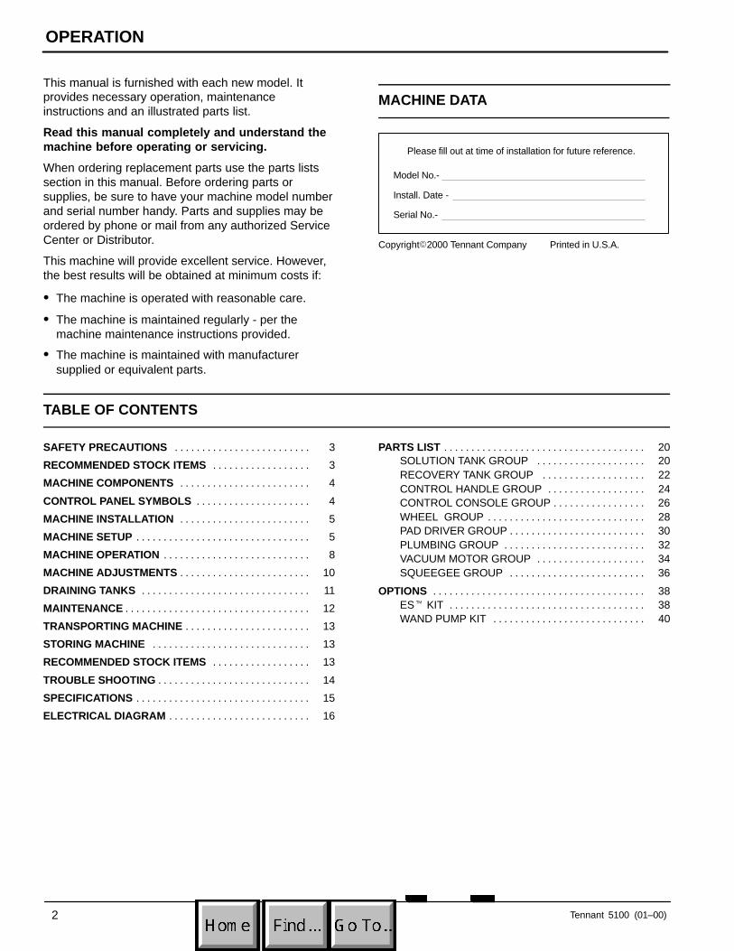
GROUNDING INSTRUCTIONS
Machine must be grounded. If it shouldmalfunction or breakdown, grounding provides apath of least resistance for electrical current toreduce the risk of electrical shock. This machineis equipped with a cord having anequipment–grounding conductor and groundingplug. The plug must be plugged into anappropriate outlet that is properly installed inaccordance with all local codes and ordinances.Do not remove ground pin; if missing, replaceplug before use.
Grounded
Grounding
Edge/hole
Outlet
OPERATION
4 Tennant 5100 (05–98)
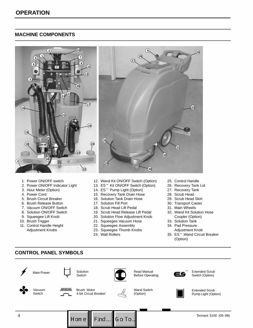
MACHINE COMPONENTS
11
2625
7
2
6
9
4
3
17
5
1
35
1413
15
16
34
22
20
21
10
29
30
32
31
2824
27
33
23
12
18
19
8
1. Power ON/OFF switch2. Power ON/OFF Indicator Light3. Hour Meter (Option)4. Power Cord5. Brush Circuit Breaker6. Brush Release Button7. Vacuum ON/OFF Switch8. Solution ON/OFF Switch9. Squeegee Lift Knob
10. Brush Trigger11. Control Handle Height
Adjustment Knobs
12. Wand Kit ON/OFF Switch (Option)13. ES� Kit ON/OFF Switch (Option)14. ES� Pump Light (Option)15. Recovery Tank Drain Hose16. Solution Tank Drain Hose17. Solution Fill Port18. Scrub Head Lift Pedal19. Scrub Head Release Lift Pedal20. Solution Flow Adjustment Knob21. Squeegee Vacuum Hose22. Squeegee Assembly23. Squeegee Thumb Knobs24. Wall Rollers
25. Control Handle26. Recovery Tank Lid27. Recovery Tank28. Scrub Head29. Scrub Head Skirt30. Transport Caster31. Main Wheels32. Wand Kit Solution Hose
Coupler (Option)33. Solution Tank34. Pad Pressure
Adjustment Knob35. ES�,Wand Circuit Breaker
(Option)
CONTROL PANEL SYMBOLS
Main Power
VacuumSwitch
SolutionSwitch
Brush Motor 4.5A Circuit Breaker
Read ManualBefore Operating
Wand Switch(Option)
Extended ScrubSwitch (Option)
Extended ScrubPump Light (Option)
�
OPERATION
Tennant 5100 (04–97) 5
MACHINE INSTALLATION
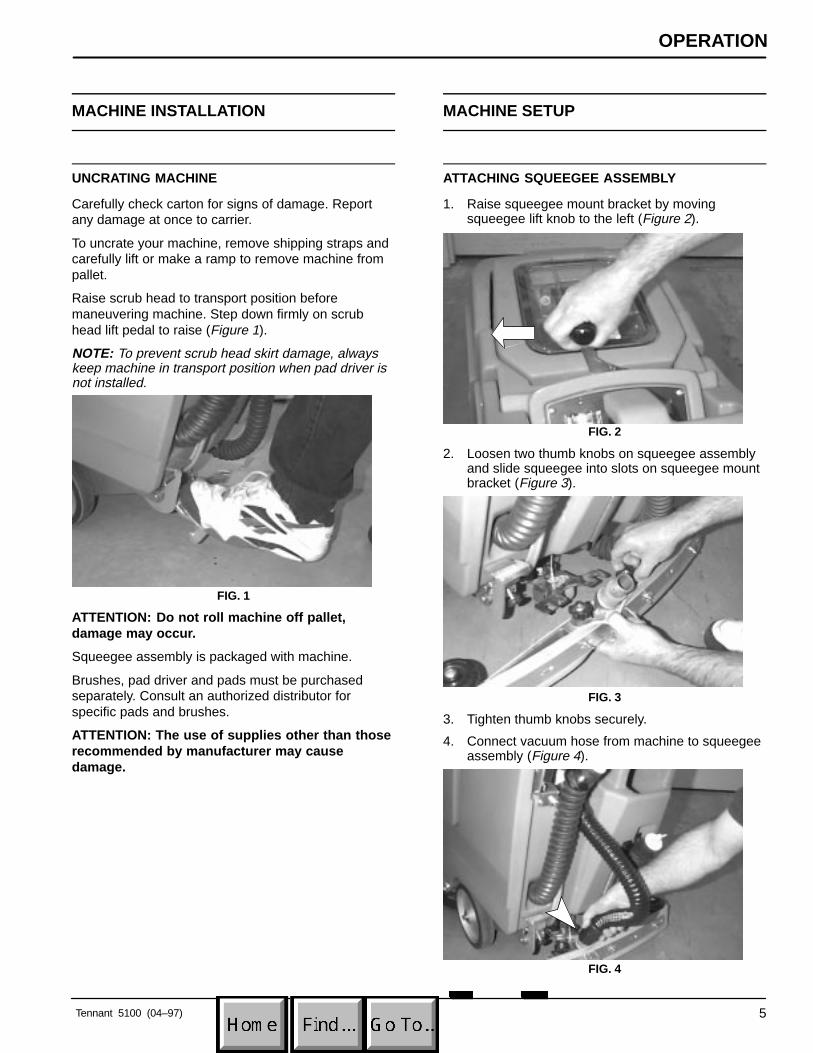
UNCRATING MACHINE
Carefully check carton for signs of damage. Reportany damage at once to carrier.
To uncrate your machine, remove shipping straps andcarefully lift or make a ramp to remove machine frompallet.
Raise scrub head to transport position beforemaneuvering machine. Step down firmly on scrubhead lift pedal to raise (Figure 1).
NOTE: To prevent scrub head skirt damage, alwayskeep machine in transport position when pad driver isnot installed.
FIG. 1
ATTENTION: Do not roll machine off pallet,damage may occur.
Squeegee assembly is packaged with machine.
Brushes, pad driver and pads must be purchasedseparately. Consult an authorized distributor forspecific pads and brushes.
ATTENTION: The use of supplies other than thoserecommended by manufacturer may causedamage.
MACHINE SETUP
ATTACHING SQUEEGEE ASSEMBLY
1. Raise squeegee mount bracket by movingsqueegee lift knob to the left (Figure 2).
FIG. 2
2. Loosen two thumb knobs on squeegee assemblyand slide squeegee into slots on squeegee mountbracket (Figure 3).
FIG. 3
3. Tighten thumb knobs securely.
4. Connect vacuum hose from machine to squeegeeassembly (Figure 4).
FIG. 4
OPERATION
6 Tennant 5100 (01–00)
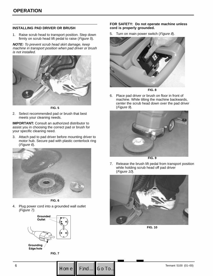
INSTALLING PAD DRIVER OR BRUSH
1. Raise scrub head to transport position. Step downfirmly on scrub head lift pedal to raise (Figure 5).
NOTE: To prevent scrub head skirt damage, keepmachine in transport position when pad driver or brushis not installed.
FIG. 5
2. Select recommended pad or brush that bestmeets your cleaning needs.
IMPORTANT: Consult an authorized distributor toassist you in choosing the correct pad or brush foryour specific cleaning need.
3. Attach pad to pad driver before mounting driver tomotor hub. Secure pad with plastic centerlock ring(Figure 6).
FIG. 6
4. Plug power cord into a grounded wall outlet (Figure 7).
Grounded
Grounding
Edge/hole
Outlet
FIG. 7
FOR SAFETY: Do not operate machine unlesscord is properly grounded.
5. Turn on main power switch (Figure 8).
FIG. 8
6. Place pad driver or brush on floor in front ofmachine. While tilting the machine backwards,center the scrub head down over the pad driver(Figure 9).
FIG. 9
7. Release the brush lift pedal from transport positionwhile holding scrub head off pad driver (Figure 10).
FIG. 10
OPERATION
Tennant 5100 (01–00) 7
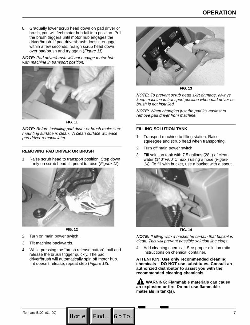
8. Gradually lower scrub head down on pad driver orbrush, you will feel motor hub fall into position. Pullthe brush triggers until motor hub engages thedriver/brush. If pad driver/brush doesn’t engagewithin a few seconds, realign scrub head downover pad/brush and try again (Figure 11).
NOTE: Pad driver/brush will not engage motor hubwith machine in transport position.
FIG. 11
NOTE: Before installing pad driver or brush make suremounting surface is clean. A clean surface will easepad driver removal later.
REMOVING PAD DRIVER OR BRUSH
1. Raise scrub head to transport position. Step downfirmly on scrub head lift pedal to raise (Figure 12).
FIG. 12
2. Turn on main power switch.
3. Tilt machine backwards.
4. While pressing the “brush release button”, pull andrelease the brush trigger quickly. The paddriver/brush will automatically spin off motor hub.If it doesn’t release, repeat step (Figure 13).
FIG. 13
NOTE: To prevent scrub head skirt damage, alwayskeep machine in transport position when pad driver orbrush is not installed.
NOTE: When changing just the pad it’s easiest toremove pad driver from machine.
FILLING SOLUTION TANK
1. Transport machine to filling station. Raisesqueegee and scrub head when transporting.
2. Turn off main power switch.
3. Fill solution tank with 7.5 gallons (28L) of cleanwater (140°F/60°C max.) using a hose (Figure14). To fill with bucket, use a bucket with a spout .
FIG. 14
NOTE: If filling with a bucket be certain that bucket isclean. This will prevent possible solution line clogs.
4. Add cleaning chemical. See proper dilution ratioinstructions on chemical container.
ATTENTION: Use only recommended cleaningchemicals – DO NOT use substitutes. Consult anauthorized distributor to assist you with therecommended cleaning chemicals.
WARNING: Flammable materials can causean explosion or fire. Do not use flammablematerials in tank(s).
OPERATION
8 Tennant 5100 (01–00)
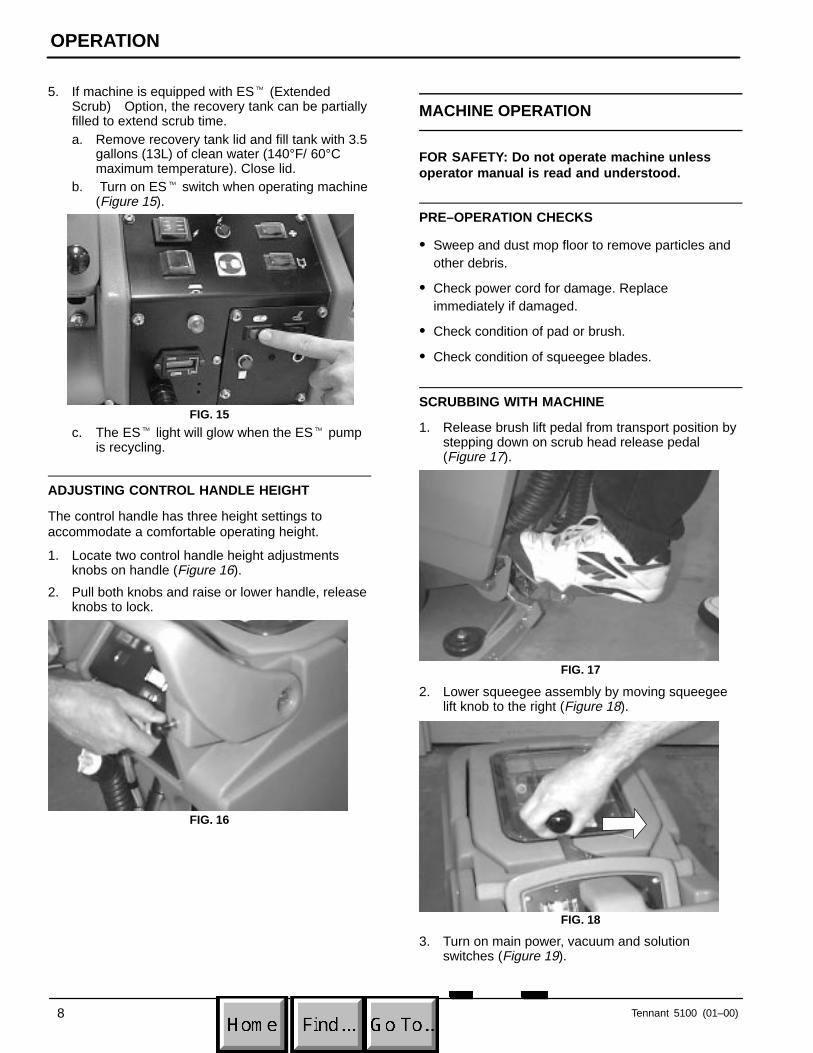
5. If machine is equipped with ES� (ExtendedScrub) Option, the recovery tank can be partiallyfilled to extend scrub time.a. Remove recovery tank lid and fill tank with 3.5
gallons (13L) of clean water (140°F/ 60°Cmaximum temperature). Close lid.
b. Turn on ES� switch when operating machine(Figure 15).
FIG. 15
c. The ES� light will glow when the ES� pumpis recycling.
ADJUSTING CONTROL HANDLE HEIGHT
The control handle has three height settings toaccommodate a comfortable operating height.
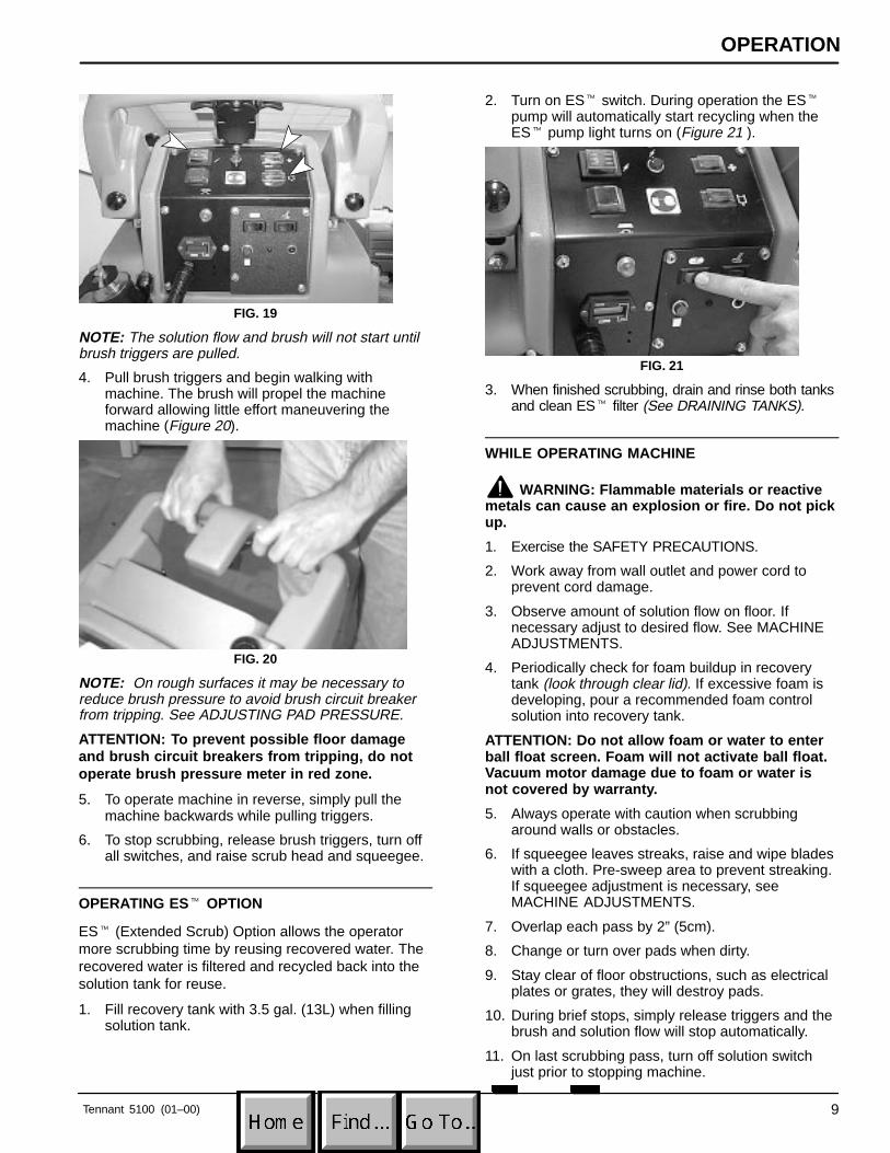
1. Locate two control handle height adjustmentsknobs on handle (Figure 16).
2. Pull both knobs and raise or lower handle, releaseknobs to lock.
FIG. 16
MACHINE OPERATION
FOR SAFETY: Do not operate machine unlessoperator manual is read and understood.
PRE–OPERATION CHECKS
� Sweep and dust mop floor to remove particles andother debris.
� Check power cord for damage. Replaceimmediately if damaged.
� Check condition of pad or brush.
� Check condition of squeegee blades.
SCRUBBING WITH MACHINE
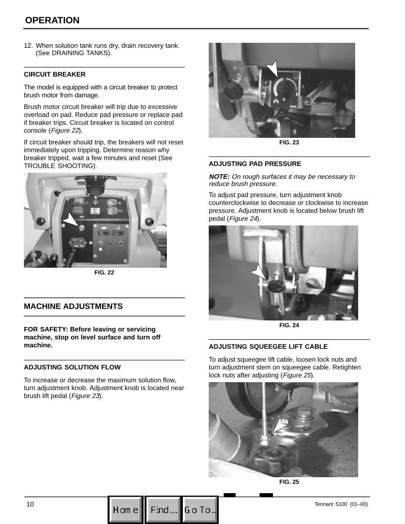
1. Release brush lift pedal from transport position bystepping down on scrub head release pedal(Figure 17).
FIG. 17
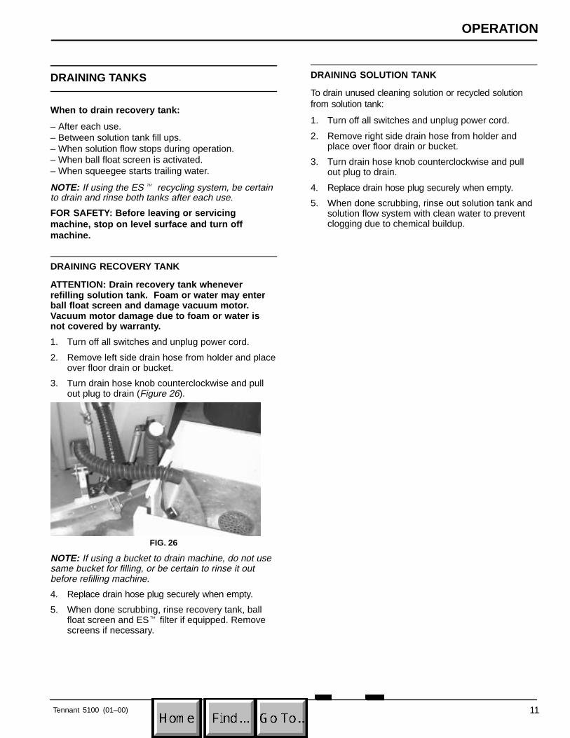
2. Lower squeegee assembly by moving squeegeelift knob to the right (Figure 18).
FIG. 18
3. Turn on main power, vacuum and solutionswitches (Figure 19).
OPERATION
Tennant 5100 (01–00) 9
FIG. 19
NOTE: The solution flow and brush will not start untilbrush triggers are pulled.
4. Pull brush triggers and begin walking withmachine. The brush will propel the machineforward allowing little effort maneuvering themachine (Figure 20).
FIG. 20
NOTE: On rough surfaces it may be necessary toreduce brush pressure to avoid brush circuit breakerfrom tripping. See ADJUSTING PAD PRESSURE.
ATTENTION: To prevent possible floor damageand brush circuit breakers from tripping, do notoperate brush pressure meter in red zone.
5. To operate machine in reverse, simply pull themachine backwards while pulling triggers.
6. To stop scrubbing, release brush triggers, turn offall switches, and raise scrub head and squeegee.
OPERATING ES� OPTION
ES� (Extended Scrub) Option allows the operatormore scrubbing time by reusing recovered water. Therecovered water is filtered and recycled back into thesolution tank for reuse.
1. Fill recovery tank with 3.5 gal. (13L) when fillingsolution tank.
2. Turn on ES� switch. During operation the ES�pump will automatically start recycling when theES� pump light turns on (Figure 21 ).
FIG. 21
3. When finished scrubbing, drain and rinse both tanksand clean ES� filter (See DRAINING TANKS).
WHILE OPERATING MACHINE
WARNING: Flammable materials or reactivemetals can cause an explosion or fire. Do not pickup.
1. Exercise the SAFETY PRECAUTIONS.
2. Work away from wall outlet and power cord toprevent cord damage.
3. Observe amount of solution flow on floor. Ifnecessary adjust to desired flow. See MACHINEADJUSTMENTS.
4. Periodically check for foam buildup in recoverytank (look through clear lid). If excessive foam isdeveloping, pour a recommended foam controlsolution into recovery tank.
ATTENTION: Do not allow foam or water to enterball float screen. Foam will not activate ball float.Vacuum motor damage due to foam or water isnot covered by warranty.
5. Always operate with caution when scrubbingaround walls or obstacles.
6. If squeegee leaves streaks, raise and wipe bladeswith a cloth. Pre-sweep area to prevent streaking.If squeegee adjustment is necessary, seeMACHINE ADJUSTMENTS.
7. Overlap each pass by 2” (5cm).
8. Change or turn over pads when dirty.
9. Stay clear of floor obstructions, such as electricalplates or grates, they will destroy pads.
10. During brief stops, simply release triggers and thebrush and solution flow will stop automatically.
11. On last scrubbing pass, turn off solution switchjust prior to stopping machine.
OPERATION
10 Tennant 5100 (01–00)
12. When solution tank runs dry, drain recovery tank.(See DRAINING TANKS).
CIRCUIT BREAKER
The model is equipped with a circuit breaker to protectbrush motor from damage.
Brush motor circuit breaker will trip due to excessiveoverload on pad. Reduce pad pressure or replace padif breaker trips. Circuit breaker is located on controlconsole (Figure 22).
If circuit breaker should trip, the breakers will not resetimmediately upon tripping. Determine reason whybreaker tripped, wait a few minutes and reset (SeeTROUBLE SHOOTING).
FIG. 22
MACHINE ADJUSTMENTS
FOR SAFETY: Before leaving or servicingmachine, stop on level surface and turn offmachine.
ADJUSTING SOLUTION FLOW
To increase or decrease the maximum solution flow,turn adjustment knob. Adjustment knob is located nearbrush lift pedal (Figure 23).
FIG. 23
ADJUSTING PAD PRESSURE
NOTE: On rough surfaces it may be necessary toreduce brush pressure.
To adjust pad pressure, turn adjustment knobcounterclockwise to decrease or clockwise to increasepressure. Adjustment knob is located below brush liftpedal (Figure 24).
FIG. 24
ADJUSTING SQUEEGEE LIFT CABLE
To adjust squeegee lift cable, loosen lock nuts andturn adjustment stem on squeegee cable. Retightenlock nuts after adjusting (Figure 25).
FIG. 25
OPERATION
Tennant 5100 (01–00) 11
DRAINING TANKS
When to drain recovery tank:
– After each use.– Between solution tank fill ups.– When solution flow stops during operation.– When ball float screen is activated.– When squeegee starts trailing water.
NOTE: If using the ES� recycling system, be certainto drain and rinse both tanks after each use.
FOR SAFETY: Before leaving or servicingmachine, stop on level surface and turn offmachine.
DRAINING RECOVERY TANK
ATTENTION: Drain recovery tank wheneverrefilling solution tank. Foam or water may enterball float screen and damage vacuum motor.Vacuum motor damage due to foam or water isnot covered by warranty.
1. Turn off all switches and unplug power cord.
2. Remove left side drain hose from holder and placeover floor drain or bucket.
3. Turn drain hose knob counterclockwise and pullout plug to drain (Figure 26).
FIG. 26
NOTE: If using a bucket to drain machine, do not usesame bucket for filling, or be certain to rinse it outbefore refilling machine.
4. Replace drain hose plug securely when empty.
5. When done scrubbing, rinse recovery tank, ballfloat screen and ES� filter if equipped. Removescreens if necessary.
DRAINING SOLUTION TANK
To drain unused cleaning solution or recycled solutionfrom solution tank:
1. Turn off all switches and unplug power cord.
2. Remove right side drain hose from holder andplace over floor drain or bucket.
3. Turn drain hose knob counterclockwise and pullout plug to drain.
4. Replace drain hose plug securely when empty.
5. When done scrubbing, rinse out solution tank andsolution flow system with clean water to preventclogging due to chemical buildup.
OPERATION
12 Tennant 5100 (01–00)
MAINTENANCE
FOR SAFETY: When servicing machine, stop onlevel surface, turn off machine and unplug cordfrom wall outlet.
ATTENTION: Contact an Authorized ServiceCenter for machine repairs. Machine repairsperformed by other than an authorized person willvoid your warranty.
To keep machine in good working condition, simplyfollow the daily, weekly and monthly maintenanceprocedures.
NOTE: If equipped with optional hour meter, recordmachine hours when service was performed.
DAILY MAINTENANCE(Every 4 Hours of Operation)
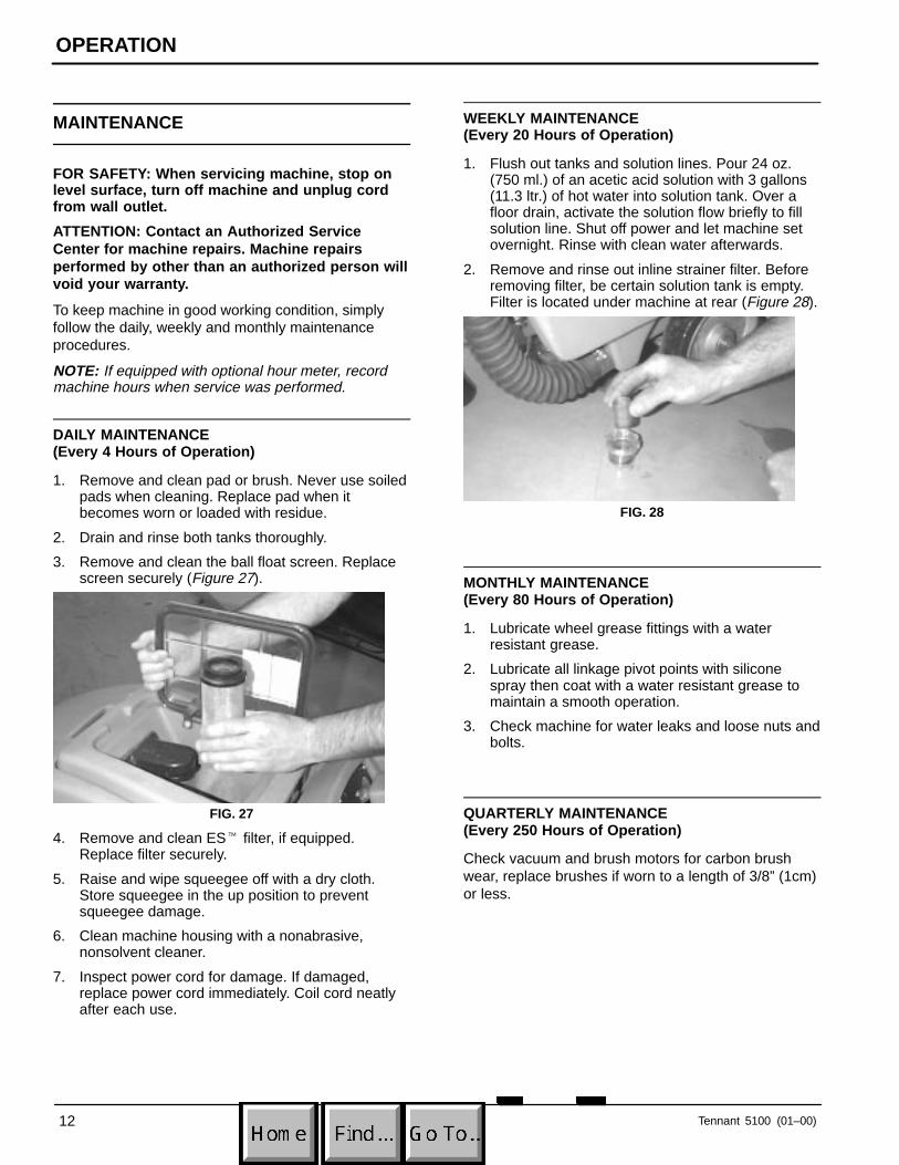
1. Remove and clean pad or brush. Never use soiledpads when cleaning. Replace pad when itbecomes worn or loaded with residue.
2. Drain and rinse both tanks thoroughly.
3. Remove and clean the ball float screen. Replacescreen securely (Figure 27).
FIG. 27
4. Remove and clean ES� filter, if equipped.Replace filter securely.
5. Raise and wipe squeegee off with a dry cloth.Store squeegee in the up position to preventsqueegee damage.
6. Clean machine housing with a nonabrasive,nonsolvent cleaner.
7. Inspect power cord for damage. If damaged,replace power cord immediately. Coil cord neatlyafter each use.
WEEKLY MAINTENANCE(Every 20 Hours of Operation)
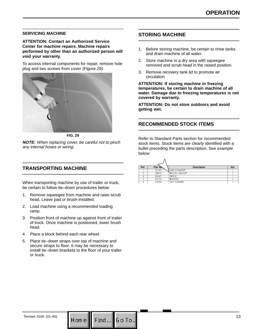
1. Flush out tanks and solution lines. Pour 24 oz.(750 ml.) of an acetic acid solution with 3 gallons(11.3 ltr.) of hot water into solution tank. Over afloor drain, activate the solution flow briefly to fillsolution line. Shut off power and let machine setovernight. Rinse with clean water afterwards.
2. Remove and rinse out inline strainer filter. Beforeremoving filter, be certain solution tank is empty.Filter is located under machine at rear (Figure 28).
FIG. 28
MONTHLY MAINTENANCE(Every 80 Hours of Operation)
1. Lubricate wheel grease fittings with a waterresistant grease.
2. Lubricate all linkage pivot points with siliconespray then coat with a water resistant grease tomaintain a smooth operation.
3. Check machine for water leaks and loose nuts andbolts.
QUARTERLY MAINTENANCE(Every 250 Hours of Operation)
Check vacuum and brush motors for carbon brushwear, replace brushes if worn to a length of 3/8” (1cm)or less.
OPERATION
Tennant 5100 (01–00) 13
SERVICING MACHINE
ATTENTION: Contact an Authorized ServiceCenter for machine repairs. Machine repairsperformed by other than an authorized person willvoid your warranty.
To access internal components for repair, remove holeplug and two screws from cover (Figure 29).
FIG. 29
NOTE: When replacing cover, be careful not to pinchany internal hoses or wiring.
TRANSPORTING MACHINE
When transporting machine by use of trailer or truck,be certain to follow tie–down procedures below:
1. Remove squeegee from machine and raise scrubhead. Leave pad or brush installed.
2. Load machine using a recommended loadingramp.
3. Position front of machine up against front of trailerof truck. Once machine is positioned, lower brushhead.
4. Place a block behind each rear wheel.
5. Place tie–down straps over top of machine andsecure straps to floor. It may be necessary toinstall tie–down brackets to the floor of your traileror truck.
STORING MACHINE
1. Before storing machine, be certain to rinse tanksand drain machine of all water.
2. Store machine in a dry area with squeegeeremoved and scrub head in the raised position.
3. Remove recovery tank lid to promote aircirculation.
ATTENTION: If storing machine in freezingtemperatures, be certain to drain machine of allwater. Damage due to freezing temperatures is notcovered by warranty.
ATTENTION: Do not store outdoors and avoidgetting wet.
RECOMMENDED STOCK ITEMS
Refer to Standard Parts section for recommendedstock items. Stock Items are clearly identified with abullet preceding the parts description. See examplebelow:
OPERATION
14 Tennant 5100 (08–97)
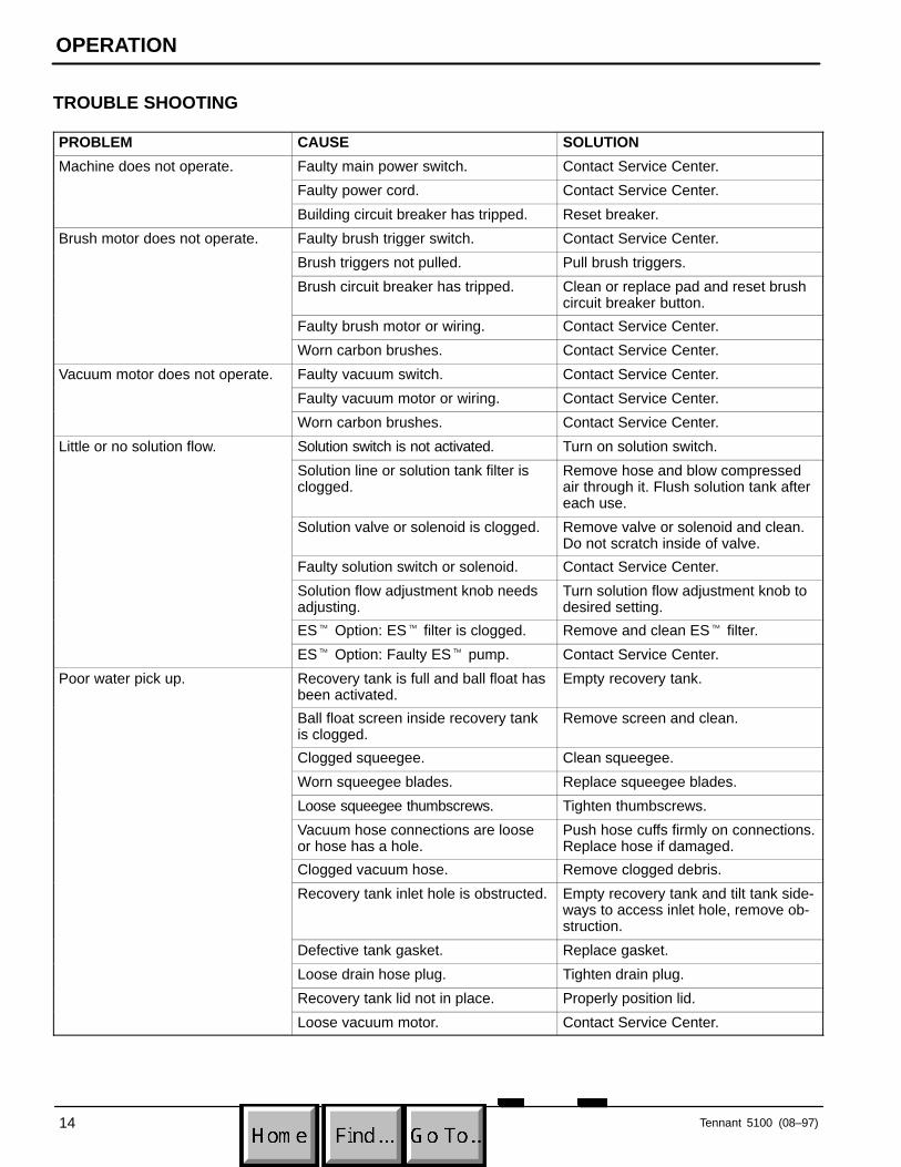
TROUBLE SHOOTING
PROBLEM CAUSE SOLUTION
Machine does not operate. Faulty main power switch. Contact Service Center.
Faulty power cord. Contact Service Center.
Building circuit breaker has tripped. Reset breaker.
Brush motor does not operate. Faulty brush trigger switch. Contact Service Center.
Brush triggers not pulled. Pull brush triggers.
Brush circuit breaker has tripped. Clean or replace pad and reset brushcircuit breaker button.
Faulty brush motor or wiring. Contact Service Center.
Worn carbon brushes. Contact Service Center.
Vacuum motor does not operate. Faulty vacuum switch. Contact Service Center.
Faulty vacuum motor or wiring. Contact Service Center.
Worn carbon brushes. Contact Service Center.
Little or no solution flow. Solution switch is not activated. Turn on solution switch.
Solution line or solution tank filter isclogged.
Remove hose and blow compressedair through it. Flush solution tank aftereach use.
Solution valve or solenoid is clogged. Remove valve or solenoid and clean. Do not scratch inside of valve.
Faulty solution switch or solenoid. Contact Service Center.
Solution flow adjustment knob needsadjusting.
Turn solution flow adjustment knob todesired setting.
ES� Option: ES� filter is clogged. Remove and clean ES� filter.
ES� Option: Faulty ES� pump. Contact Service Center.
Poor water pick up. Recovery tank is full and ball float hasbeen activated.
Empty recovery tank.
Ball float screen inside recovery tankis clogged.
Remove screen and clean.
Clogged squeegee. Clean squeegee.
Worn squeegee blades. Replace squeegee blades.
Loose squeegee thumbscrews. Tighten thumbscrews.
Vacuum hose connections are looseor hose has a hole.
Push hose cuffs firmly on connections.Replace hose if damaged.
Clogged vacuum hose. Remove clogged debris.
Recovery tank inlet hole is obstructed. Empty recovery tank and tilt tank side-ways to access inlet hole, remove ob-struction.
Defective tank gasket. Replace gasket.
Loose drain hose plug. Tighten drain plug.
Recovery tank lid not in place. Properly position lid.
Loose vacuum motor. Contact Service Center.
OPERATION
Tennant 5100 (01–00) 15
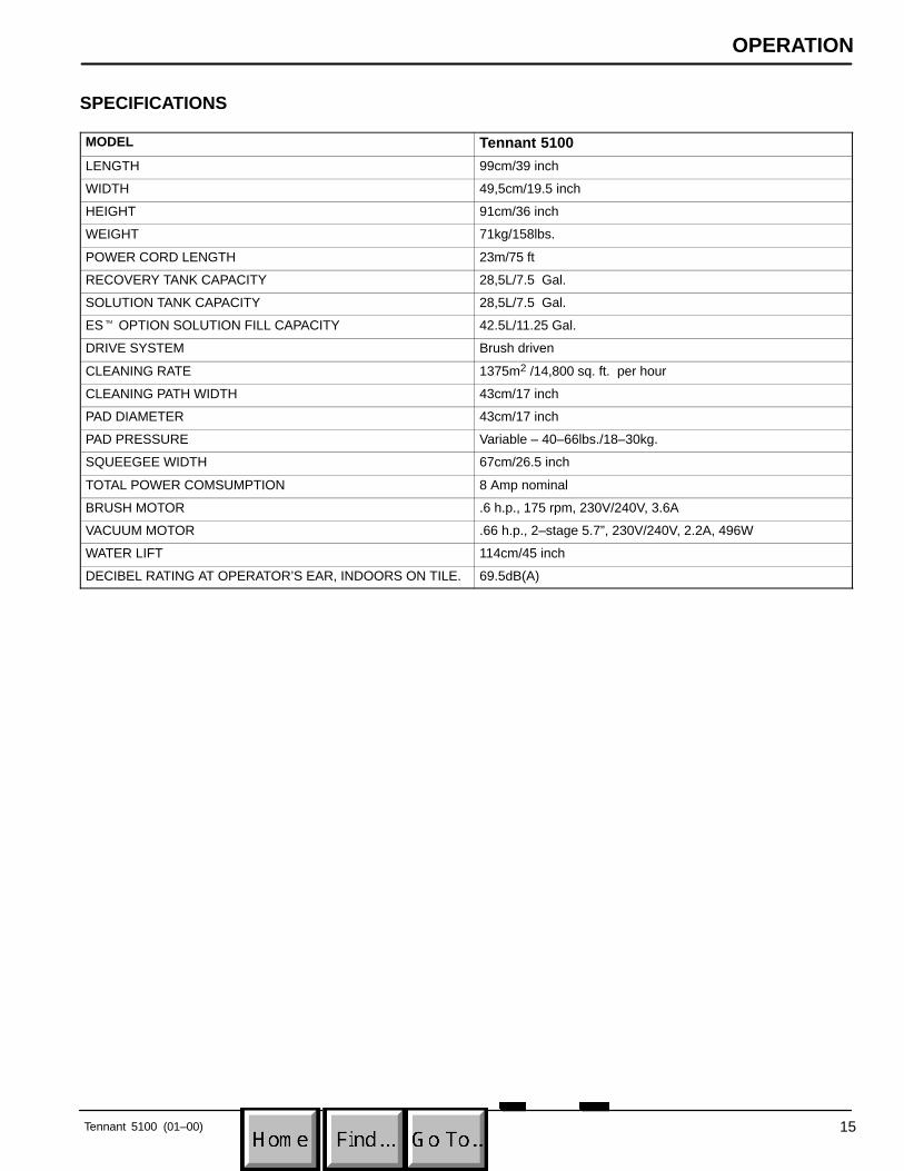
SPECIFICATIONS
MODEL Tennant 5100
LENGTH 99cm/39 inch
WIDTH 49,5cm/19.5 inch
HEIGHT 91cm/36 inch
WEIGHT 71kg/158lbs.
POWER CORD LENGTH 23m/75 ft
RECOVERY TANK CAPACITY 28,5L/7.5 Gal.
SOLUTION TANK CAPACITY 28,5L/7.5 Gal.
ES� OPTION SOLUTION FILL CAPACITY 42.5L/11.25 Gal.
DRIVE SYSTEM Brush driven
CLEANING RATE 1375m2 /14,800 sq. ft. per hour
CLEANING PATH WIDTH 43cm/17 inch
PAD DIAMETER 43cm/17 inch
PAD PRESSURE Variable – 40–66lbs./18–30kg.
SQUEEGEE WIDTH 67cm/26.5 inch
TOTAL POWER COMSUMPTION 8 Amp nominal
BRUSH MOTOR .6 h.p., 175 rpm, 230V/240V, 3.6A
VACUUM MOTOR .66 h.p., 2–stage 5.7”, 230V/240V, 2.2A, 496W
WATER LIFT 114cm/45 inch
DECIBEL RATING AT OPERATOR’S EAR, INDOORS ON TILE. 69.5dB(A)
ELECTRICAL DIAGRAM
Tennant 5100 (05–98)16
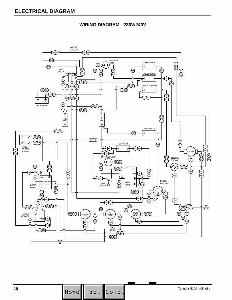
WIRING DIAGRAM - 230V/240V
INDICATOR
LIGHT
1 2
MOTOR
RELAY
GRN/YEL
BLU
BRN
GRN17
7
WHT 5
WHT BLK
34
BLK4
WHT5
BLK32
3
WHT
8
BLK
66
BLK
2 BLK
47
WHT
6
32
BLK
10 BLK
4
BLK
WHT
YEL
BLU
BLK
3
WHT
17
GRN
6
YEL
3
WHT
17
GRN
GRY
RED
BLK
12
14
BLU
14
30BLK
12BLK
30
BLK
12
BLK
18 BRN
22 BLK
11
18
11
WHT
WHT
BRN
BLK
22
28
33
26
35
36
48
29
ORG
WHT ORG
WHTPUR
BRN
RED
GRN
9
WHT21
GRN
17
45
48
27
27
47
GRN
WHT
25
GRN
GRN
GRNBLU
GRN
BRN
36 PUR25
29
30
16 BLK
BLK
WHT
BRN
23
BRN
45 GRN
25 WHT
WHT
35
20BLK
GRN
BLK
BLKWHT
RED
GRN
45
GRN
8
BLK66BLK
16
BLK
42
42
13 WHT
BRN
BRN
50BRN
68RED
70RED
70RED
WHT
WHT
WHT
4.5
AMP
BRUSH SWITCH
TANK "FULL" LIGHTSOLUTION
SOLENOID
VACUUM SWITCH
SOLUTION SWITCH
HOUR METER
.5
AMP
WAND SWITCH
ES SWITCH
VACUUM
WAND
PUMP
ES
PUMPBRUSH
MAIN
SWITCH
GROUND
STANDOFF
BRIDGE
RECTIFIERTIMER
RELAYFLOAT
SWITCH
BRUSH
RELEASE
BUTTON
BRIDGE
RECTIFIER
+ AC
AC-
AC
AC
-+
ELECTRICAL DIAGRAM
Tennant 5100 (05–98) 17
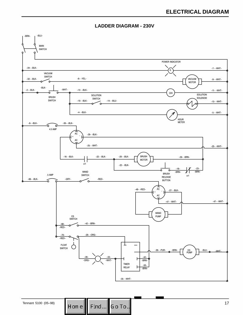
LADDER DIAGRAM - 230V
ESPUMP
TIMER
RELAY
G
AC
AC
-+
AC
AC
-+
-2- -BLK-
-32- -BLK-
-34- -BLK-
-12- -BLK-
-6- -YEL-
-10- -BLK-
-4- -BLK-
-8- -BLK- -30- -BLK-
-29- -BLK-
-25- -WHT-
-16- -BLK- -22- -BLK-
-14- -BLU-
-7- -WHT-
-9- -WHT-
-11- -WHT-
-13- -WHT-
-5- -WHT-
-25- -WHT-
-29- -BRN--20- -BLK-
-22- -BLK-
-23-
-BRN-
-18-
-BRN-
-27- -BLK-
-47- -WHT-
-48- -RED-
-66- -BLK- -GRY-
-68-
-RED-
-70-
-RED-
-BRN- -BLU--36- -PUR- -WHT-
-47- -WHT-
-42- -BRN-
-26- -ORG-
-33-
-WHT-
-35- -WHT-
-50-
-BRN-
-28-
-ORG-
cr1
cr1
POWER INDICATOR
-BLU-
MAIN
SWITCH
-RED-
-42-
-BRN-
-BRN-
-BLK--WHT-
HOUR
METER
4.5 AMP
SOLUTION
SOLENOIDBRUSH
SWITCH
CR1
.5 AMP
FLOAT
SWITCH
ES
SWITCH
WAND
SWITCHBRUSH
RELEASE
BUTTON
SOLUTION
SWITCH
VACUUM
SWITCHVACUUM
MOTOR
WAND
PUMP
BRUSH
MOTOR
ELECTRICAL DIAGRAM
Tennant 5100 (01–00)18
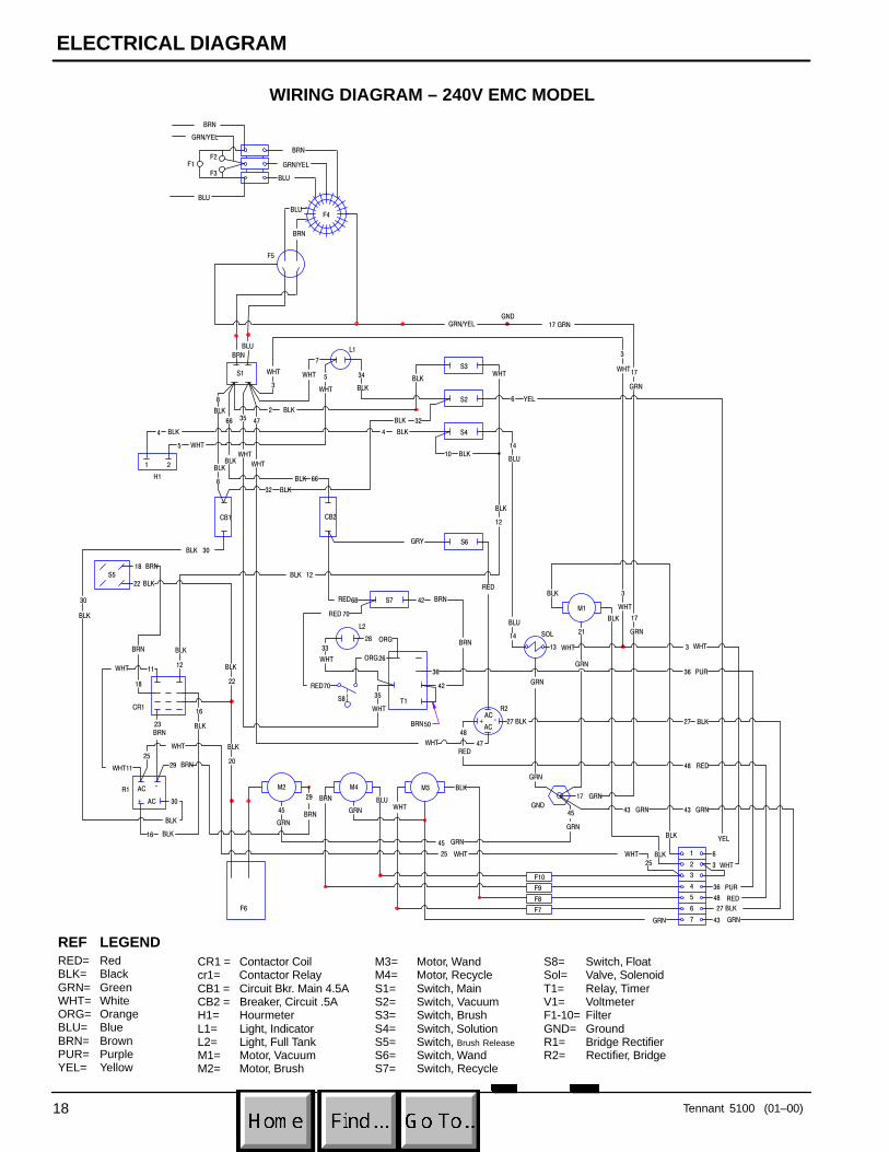
WIRING DIAGRAM – 240V EMC MODEL
S8= Switch, FloatSol= Valve, SolenoidT1= Relay, TimerV1= VoltmeterF1-10= FilterGND= GroundR1= Bridge RectifierR2= Rectifier, Bridge
BRN
BLU
WHT
ORG
H1
L1
1 2
CR1
F5
GND
F6 F7
F8
F9
F10
GRN/YEL 17 GRN
7
WHT 5
WHT BLK
34
BLK4
WHT5
BLK32
3
WHT
8
BLK
66
BLK
2 BLK
47
WHT
6
32
BLK
10 BLK
4
BLK
WHT
BLU
BLK
3
WHT17
GRN
BLK 3
WHT
17
GRN
GRY
RED
BLK
12
14
BLU
14
30BLK
12BLK
30
BLK
12
BLK
18 BRN
22 BLK
11
18
11
WHT
WHT
BRN
BLK
22
28
33
26
35
36
48
29
ORG
WHT
WHT
BRN
RED
GRN
BLK
21
GRN
17
45
47
GRN
GRN
GRN
25
29
30
16 BLK
BLK
WHT
BRN
23
BRN
45 GRN
25 WHT
WHT
35
WHT
GRN
45
GRN
8
BLK
66BLK
16
BLK
42
42
13
BRN
BRN
50BRN
68RED
70RED
70RED
GRN/YEL
BLU
BLU
BRN
BRN
BLK
20
BRN BLUWHT
BLK
GRN 43 GRN
27 BLK
48 RED
36 PUR
3 WHT
BLK
BLK
25
WHT 6
YEL
27 BLK
YEL
BLU
GRN/YEL
BRN
43 GRN GRN43
RED48
BLK27
PUR36
WHT3
CB1
S3
L2
SOL
S2
S4
CB2
S6
S7
M1
M3M4M2
S1
GND
R2T1S8
S5
R1
F1F2
F3
F4
AC
AC
-+
+ AC
AC-
1
2
3
4
5
6
7
REF LEGENDRED= RedBLK= BlackGRN= GreenWHT= WhiteORG= OrangeBLU= BlueBRN= BrownPUR= PurpleYEL= Yellow
CR1 = Contactor Coilcr1= Contactor RelayCB1 = Circuit Bkr. Main 4.5ACB2 = Breaker, Circuit .5AH1= HourmeterL1= Light, IndicatorL2= Light, Full TankM1= Motor, VacuumM2= Motor, Brush
M3= Motor, WandM4= Motor, RecycleS1= Switch, MainS2= Switch, VacuumS3= Switch, BrushS4= Switch, SolutionS5= Switch, Brush Release
S6= Switch, WandS7= Switch, Recycle
ELECTRICAL DIAGRAM
Tennant 5100 (01–00) 19
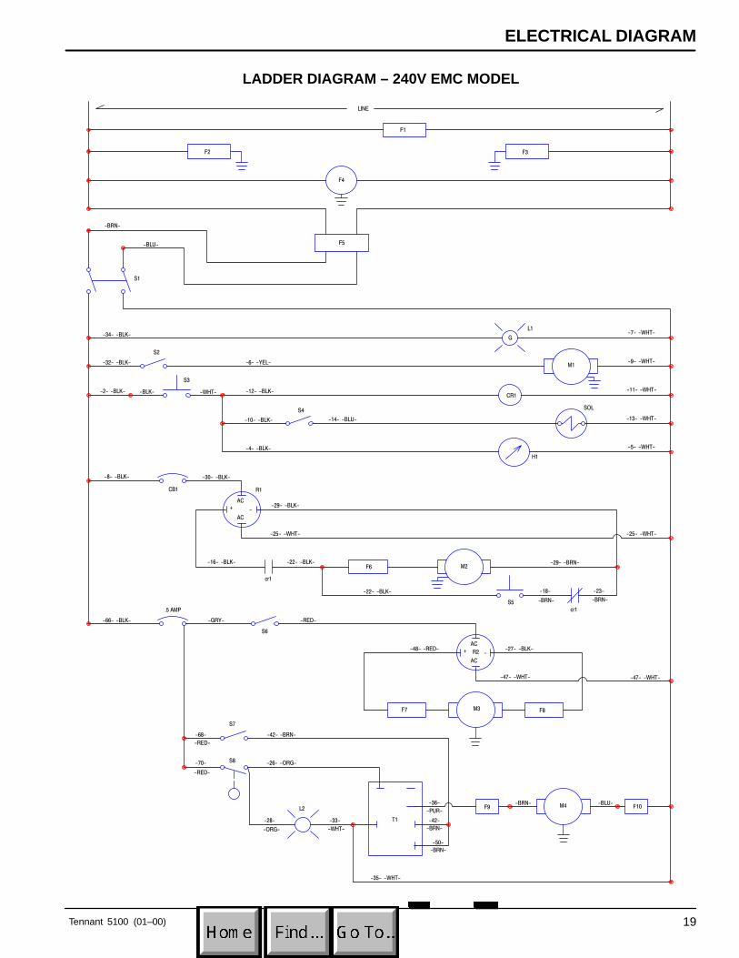
LADDER DIAGRAM – 240V EMC MODEL
LINE
R1
L2
T1
AC
AC
-+
AC
AC
-+
G
F5
F4
F2 F3
F1
F6
R2
F7 F8
F9 F10M4
M3
M2
M1
-2- -BLK-
-32- -BLK-
-34- -BLK-
-12- -BLK-
-6- -YEL-
-10- -BLK-
-4- -BLK-
-8- -BLK- -30- -BLK-
-29- -BLK-
-25- -WHT-
-16- -BLK- -22- -BLK-
-14- -BLU-
-7- -WHT-
-9- -WHT-
-11- -WHT-
-13- -WHT-
-5- -WHT-
-25- -WHT-
-29- -BRN-
-22- -BLK- -23-
-BRN-
-18-
-BRN-
-27- -BLK-
-47- -WHT-
-48- -RED-
-66- -BLK- -GRY-
-68-
-RED-
-70-
-RED-
-BRN- -BLU-
-47- -WHT-
-42- -BRN-
-26- -ORG-
-33-
-WHT-
-35- -WHT-
-50-
-BRN-
-28-
-ORG-
cr1
cr1
L1
-BLU-
S1
-RED-
-42-
-BRN-
-BRN-
-BLK- -WHT-
-36-
-PUR-
H1
CB1
SOL
S3
CR1
.5 AMP
S8
S7
S5
S4
S2
S6
PARTS LIST
Tennant 5100 (01–00)20
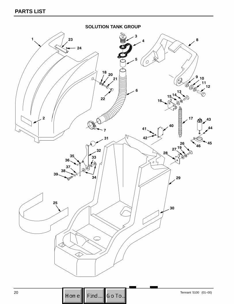
SOLUTION TANK GROUP
26
1
2
6
5
7
3
4 8
9 1011
12
13
1516
14
17
28
29
27 19
30
31
32
33
34
3536
3738
39
2120
18
22
24
25
23
4041
42
43
44
4546
PARTS LIST
Tennant 5100 (01–00) 21
SOLUTION TANK GROUP
REF PART # DESCRIPTION QTY.
1 609205 COVER, BATTERY, TEAL 1
2 120192 DECAL, TENNANT LOGO 1
3 621324 PLUG, EXPANSION 1
4 578441 �STRAP, DRAIN HOSE 1
5 630394 �SLEEVE 1
6 601459 �HOSE, DRAIN 1
7 140307 CLAMP 1
8 609207 HANDLE, TEAL 1
9 601434 SPACER 2
10 140045 WASHER, FLAT 2
11 140024 WASHER, LOCK 2
12 601435 SCREW, M12X30MM 2
13 140275 SCREW, M8x1.25x16MM 2
14 140015 WASHER, LOCK 2
15 140027 WASHER, FLAT 2
16 601496 CLIP, HOSE–SPRING 1
17 140423 SPRING 1
18 140027 WASHER, FLAT 2
19 140016 WASHER, LOCK 1
20 200 370 019 WASHER, LOCK 2
21 602 069 000 SCREW, M8X1.25X50 2
22 130175 PLUG, DOME 2
23 603165 PLATE, COVER 1
24 140340 SCREW, #10X5/8 2
REF PART # DESCRIPTION QTY.
25 604707 SHIELD, BRUSH MOTOR 1
26 578187000 SCREW, M06X12MM 1
27 140000 WASHER, FLAT 1
28 601460 CLIP, DRAIN HOSE 1
29 609201 TANK, SOLUTION, TEAL 1
30 609066 DECAL, 5100 2
31 601425 KNOB, SQ. LEVER 1
32 601426 LEVER, SQUEEGEE 1
33 601427 SPACER 1
34 601437 WASHER, NYLON 2
35 601428 CABLE, SQUEEGEE 1
36 601476 NUT 1
37 140055 WASHER, FLAT 1
38 140015 WASHER, LOCK 1
39 630425 SCREW, M8X20MM 1
40 606350 SEAL, POWER CORD (EMC MODEL) 1
41 140825 SCREW, #6X1/2 (EMC MODEL) 4
42 140041 WASHER, FENDER (EMC MODEL) 4
43 600383 FILTER, RFI (EMC MODEL) 4
44 140823 SCREW, 10–24X5/8 (EMC MODEL) 4
45 600749 CLAMP (EMC MODEL) 4
46 140552 NUT, NYLOCK (EMC MODEL) 4
� RECOMMENDED STOCK ITEMS
PARTS LIST
Tennant 5100 (05–98)22
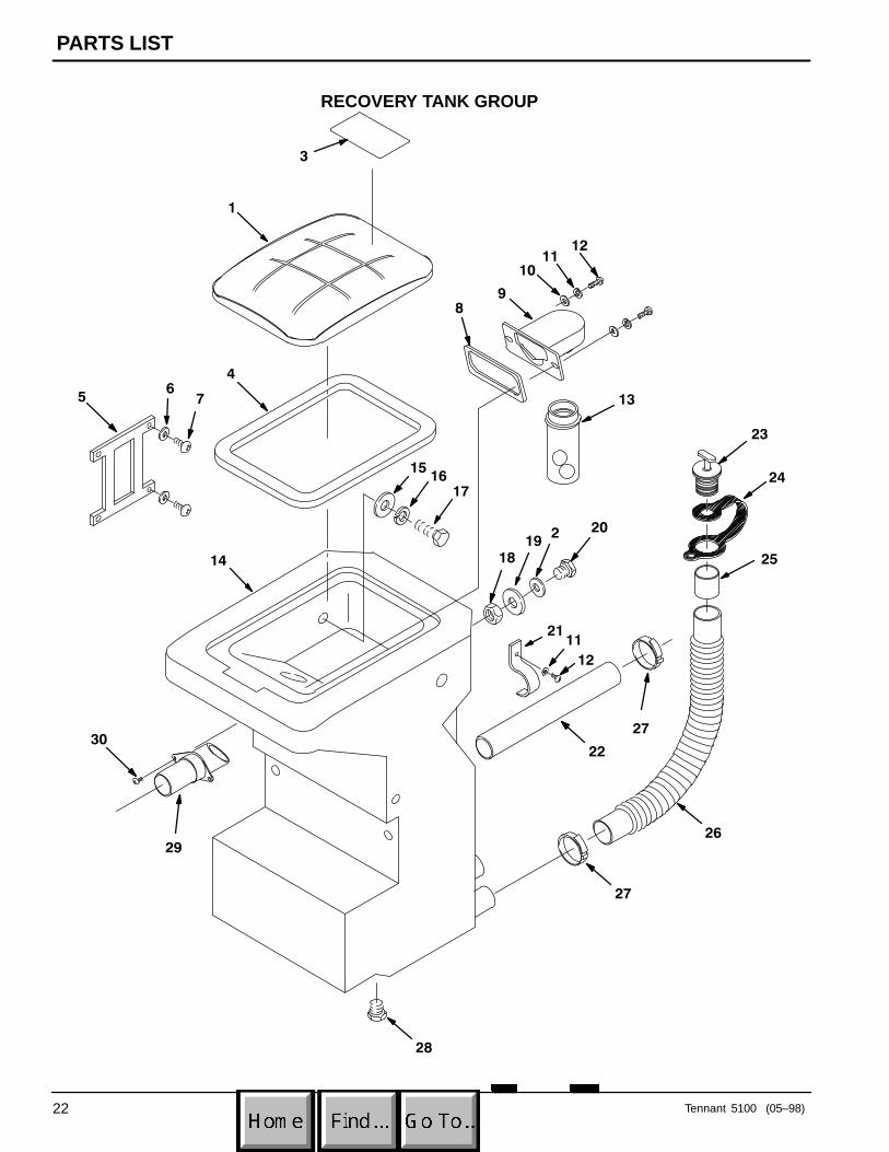
RECOVERY TANK GROUP
3
5
1
10
8
13
1211
9
7
46
23
24
25
20
18
15
19
2111
12
22
26
27
28
14
29
30
1716
2
27
PARTS LIST
Tennant 5100 (01–00) 23
RECOVERY TANK GROUP
REF PART # DESCRIPTION QTY.
1 630055 �COVER, TANK 1
2 601437 WASHER, NYLON 1
3 630420 DECAL, FLAMM. MAT’L 1
4 630367 �GASKET, REC. TANK 1
5 630056 STRAP, TANK COVER 1
6 630390 WASHER, FLAT 4
7 3701.6 SCREW, #6X3/8 4
8 630255 GASKET, FLOAT MOUNT 1
9 630053 MOUNT, FLOAT CAGE 1
10 140000 WASHER, FLAT 2
11 140016 WASHER, LOCK 3
12 600385 SCREW, M06X1.0x20MM 3
13 630052 �FLOAT CAGE W/BALL 1
14 609203 TANK, RECOVERY, TEAL 1
15 140027 WASHER, FLAT 2
REF PART # DESCRIPTION QTY.
16 140015 WASHER, LOCK 2
17 200607491 SCREW, M08X25MM 2
18 603418 NUT 1
19 14194 WASHER, RUBBER 1
20 603417 SCREW, 5/8–11X1 1
21 601462 CLAMP 1
22 240177 TUBE, BASE INLET 1
23 621324 PLUG, EXPANSION 1
24 578441 STRAP, DRAIN HOSE 1
25 630394 SLEEVE, DRAIN HOSE 1
26 601459 HOSE, DRAIN 1 1/2X15” 1
27 140307 CLAMP 2
28 630147 PLUG, 3/4 NPT 1
29 160485 �ADAPTER, HOSE 1
30 200070382 SCREW, M05X10MM 2
� RECOMMENDED STOCK ITEMS
PARTS LIST
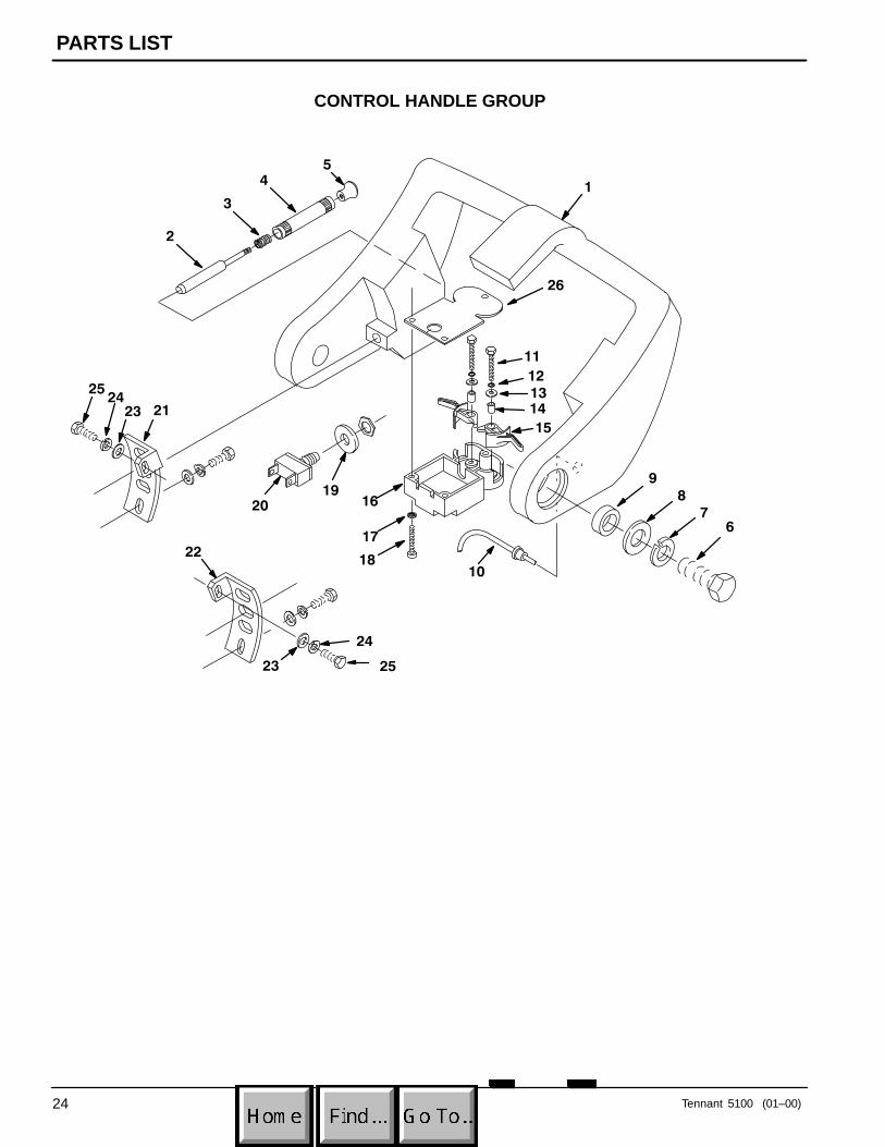
Tennant 5100 (01–00)24
CONTROL HANDLE GROUP
21
4
3
2
5
1
8
121314
11
15
1619
20
17
18
9
67
10
23
24
25
22
2324
25
26
PARTS LIST
Tennant 5100 (01–00) 25
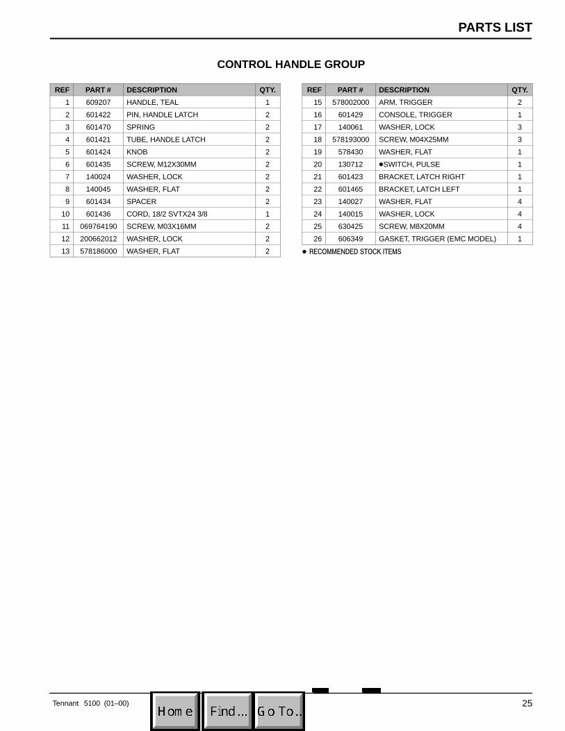
CONTROL HANDLE GROUP
REF PART # DESCRIPTION QTY.
1 609207 HANDLE, TEAL 1
2 601422 PIN, HANDLE LATCH 2
3 601470 SPRING 2
4 601421 TUBE, HANDLE LATCH 2
5 601424 KNOB 2
6 601435 SCREW, M12X30MM 2
7 140024 WASHER, LOCK 2
8 140045 WASHER, FLAT 2
9 601434 SPACER 2
10 601436 CORD, 18/2 SVTX24 3/8 1
11 069764190 SCREW, M03X16MM 2
12 200662012 WASHER, LOCK 2
13 578186000 WASHER, FLAT 2
REF PART # DESCRIPTION QTY.
15 578002000 ARM, TRIGGER 2
16 601429 CONSOLE, TRIGGER 1
17 140061 WASHER, LOCK 3
18 578193000 SCREW, M04X25MM 3
19 578430 WASHER, FLAT 1
20 130712 �SWITCH, PULSE 1
21 601423 BRACKET, LATCH RIGHT 1
22 601465 BRACKET, LATCH LEFT 1
23 140027 WASHER, FLAT 4
24 140015 WASHER, LOCK 4
25 630425 SCREW, M8X20MM 4
26 606349 GASKET, TRIGGER (EMC MODEL) 1
� RECOMMENDED STOCK ITEMS
PARTS LIST
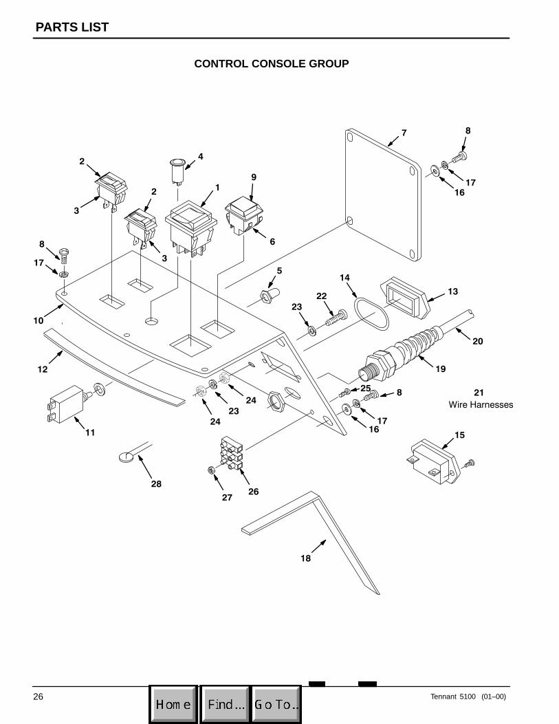
Tennant 5100 (01–00)26
CONTROL CONSOLE GROUP
12
6
3
4
7
9
8
11
12
8
10
1716
16
17
13
14
17
18
2
15
8
5
20
19
Wire Harnesses
21
3
2324
24
2322
25
2627
28

PARTS LIST
Tennant 5100 (01–00) 27
CONTROL CONSOLE GROUP
REF PART # DESCRIPTION QTY.
1 602670 �SWITCH, DPST 1
2 578720 BOOT, ROCKER SWITCH 2
3 578 005 000 �SWITCH, ROCKER 2
4 130691 �LIGHT, GRN INDICATOR 1
5 578734 BOOT, CIRCUIT BREAKER 1
6 603410 �SWITCH, MOMENTARY GREEN 1
7 601415 PANEL 1
8 578141000 SCREW, M5X10MM 9
9 130765 BOOT, PUSH BUTTON 1
10 601492 PANEL, CONSOLE 1
11 582510 �BREAKER, CIRCUIT 4.5AMP 1
12 601497 GASKET, 7.25” 2
13 222519 PLUG, HOUR METER 1
14 603224 O–RING 1
15 604745 �METER, HOUR (OPTIONAL) 1
16 140011 WASHER, FLAT 6
REF PART # DESCRIPTION QTY.
17 140018 WASHER, LOCK 9
18 601498 GASKET, 8” 2
19 130167 CORD GRIP 1
20 600396 CORD, POWER 75’/23M 1
N/S 130125 TERMINAL RING, POWER CORD 1
N/S 281004001 TERMINAL, POWER CORD 2
21 604702 HARNESS, WIRE 1
22 578302000 SCREW 1
23 200655016 WASHER, LOCK 2
24 140297 NUT, HEX 2
25 140946 SCREW, 6–32X1 (EMC MODEL) 1
26 130005 STRIP, TERMINAL 25A(EMC MODEL)
1
27 140534 NUT, 6–32 (EMC MODEL) 1
28 606344 VARISTOR S14K 275 (EMC MODEL) 3
� RECOMMENDED STOCK ITEMS
PARTS LIST
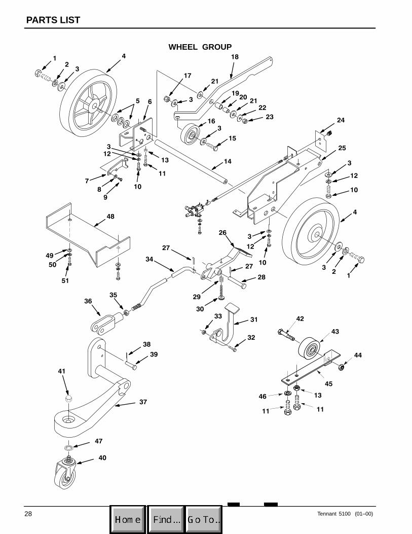
Tennant 5100 (01–00)28
WHEEL GROUP1
23
4
5
17
3
18
1920
2122
23
14
3
15
16
13
11
6
10
123
98
7
24
3
25
12
10
4
1
32
13
10
12
326
27
28
31
32
3330
29
34
27
3536
37
39
38
21
11
41
40
11
46
42
43
44
45
47
48
51
50
49
PARTS LIST
Tennant 5100 (01–00) 29
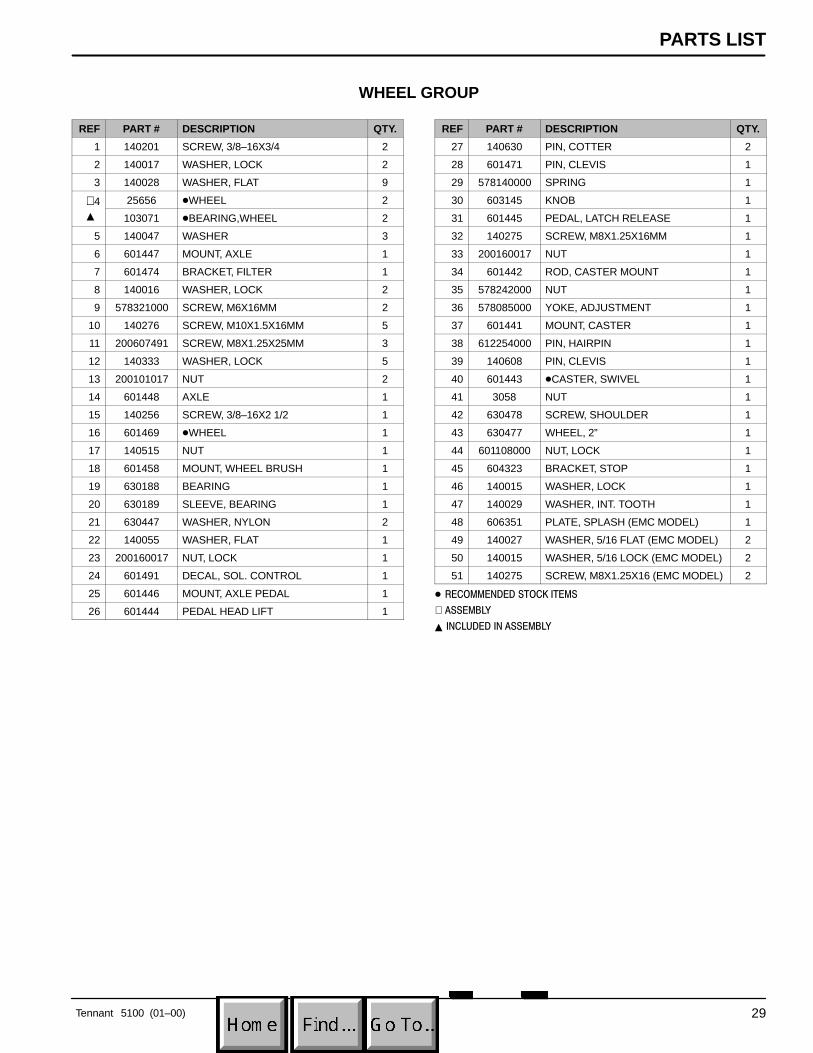
WHEEL GROUP
REF PART # DESCRIPTION QTY.
1 140201 SCREW, 3/8–16X3/4 2
2 140017 WASHER, LOCK 2
3 140028 WASHER, FLAT 9
∇ 4 25656 �WHEEL 2∇ 4�4 103071 �BEARING,WHEEL 2
5 140047 WASHER 3
6 601447 MOUNT, AXLE 1
7 601474 BRACKET, FILTER 1
8 140016 WASHER, LOCK 2
9 578321000 SCREW, M6X16MM 2
10 140276 SCREW, M10X1.5X16MM 5
11 200607491 SCREW, M8X1.25X25MM 3
12 140333 WASHER, LOCK 5
13 200101017 NUT 2
14 601448 AXLE 1
15 140256 SCREW, 3/8–16X2 1/2 1
16 601469 �WHEEL 1
17 140515 NUT 1
18 601458 MOUNT, WHEEL BRUSH 1
19 630188 BEARING 1
20 630189 SLEEVE, BEARING 1
21 630447 WASHER, NYLON 2
22 140055 WASHER, FLAT 1
23 200160017 NUT, LOCK 1
24 601491 DECAL, SOL. CONTROL 1
25 601446 MOUNT, AXLE PEDAL 1
26 601444 PEDAL HEAD LIFT 1
REF PART # DESCRIPTION QTY.
27 140630 PIN, COTTER 2
28 601471 PIN, CLEVIS 1
29 578140000 SPRING 1
30 603145 KNOB 1
31 601445 PEDAL, LATCH RELEASE 1
32 140275 SCREW, M8X1.25X16MM 1
33 200160017 NUT 1
34 601442 ROD, CASTER MOUNT 1
35 578242000 NUT 1
36 578085000 YOKE, ADJUSTMENT 1
37 601441 MOUNT, CASTER 1
38 612254000 PIN, HAIRPIN 1
39 140608 PIN, CLEVIS 1
40 601443 �CASTER, SWIVEL 1
41 3058 NUT 1
42 630478 SCREW, SHOULDER 1
43 630477 WHEEL, 2” 1
44 601108000 NUT, LOCK 1
45 604323 BRACKET, STOP 1
46 140015 WASHER, LOCK 1
47 140029 WASHER, INT. TOOTH 1
48 606351 PLATE, SPLASH (EMC MODEL) 1
49 140027 WASHER, 5/16 FLAT (EMC MODEL) 2
50 140015 WASHER, 5/16 LOCK (EMC MODEL) 2
51 140275 SCREW, M8X1.25X16 (EMC MODEL) 2
� RECOMMENDED STOCK ITEMS
∇ ASSEMBLY
� INCLUDED IN ASSEMBLY
PARTS LIST
Tennant 5100 (05–98)30
PAD DRIVER GROUP
19
1
20
18
16
17
2
3
4
15
5
23
22
6
7
8
24
12
25
26
21
14
13
27
29 28
30
27
31
910
11
33
32
PARTS LIST
Tennant 5100 (01–00) 31
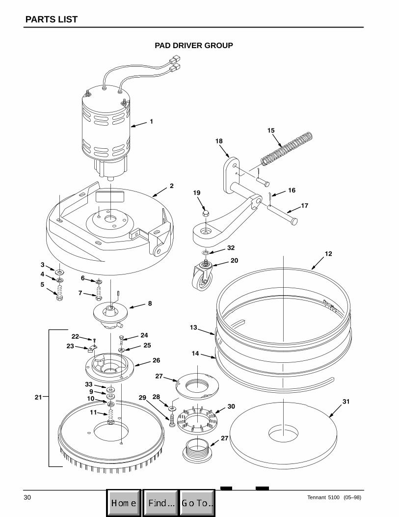
PAD DRIVER GROUP
REF PART # DESCRIPTION QTY.
∇ 1 603151 �MOTOR, BRUSH 230V .6HP 1
� 190311 �CARBON BRUSH 4� 630609 GEARBOX 1� 140632 KEY 1
2 601440 HEAD CASTING 1
3 140028 WASHER, FLAT 4
4 140333 WASHER, LOCK 4
5 140276 SCREW, M10X1.5X16MM 4
6 140017 WASHER, LOCK 4
7 140202 SCREW, 3/8–16X1 4
8 601449 HUB, BRUSH DRIVE 1
9 140027 WASHER, FLAT 1
10 140015 WASHER, LOCK 1
11 140219 SCREW, 5/16–18X1 1
12 601493 �SKIRT, SPLASH GUARD 1
13 601495 ASM., SKIRT BAND 1
14 603147 BUMPER, EXTRUSION 2.5’
15 603148 SPRING 1
16 612254000 PIN, HAIRPIN 1
17 069764083 PIN, CLEVIS 1
REF PART # DESCRIPTION QTY.
18 601441 MOUNT, CASTER 1
19 3058 NUT 1
20 601443 CASTER, SWIVEL 1
∇ 21 370000 ASM., BRUSH 17”NYLON (OPTION-AL)
1
370002 ASM., BRUSH 17” GRIT (OPTIONAL) 1
370007 ASM., BRUSH 17” POLY (OPTIONAL) 1
370003 ASM., PAD DRIVER 17” (OPTIONAL) 1
�22 603439 SCREW, #6X5/16 4
�23 603438 PLATE, WEAR 2
�24 578580 SCREW, M06X35MM 3
�25 140000 WASHER, FLAT 3
�26 601453 �PLATE, CLUTCH 1
�27 630473 �CENTERLOCK 1
�28 140007 WASHER, FLAT 3
�29 200070351 SCREW, M4X025MM 3
�30 630472 RETAINER, BRUSH PAD 1
31 NA PAD 1
32 140029 WASHER, INT. TOOTH 1
33 140028 WASHER, FLAT 1
� RECOMMENDED STOCK ITEMS
∇ ASSEMBLY
� INCLUDED IN ASSEMBLY
PARTS LIST
Tennant 5100 (05–98)32
PLUMBING GROUP
1
2
3
4
6
7
8
5
7
7
7
9
10
11
13
12
15
16
14
17
18
719
22
23
20
21
Cordset
24
PARTS LIST
Tennant 5100 (01–00) 33
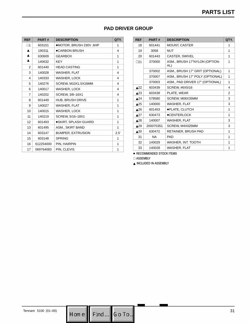
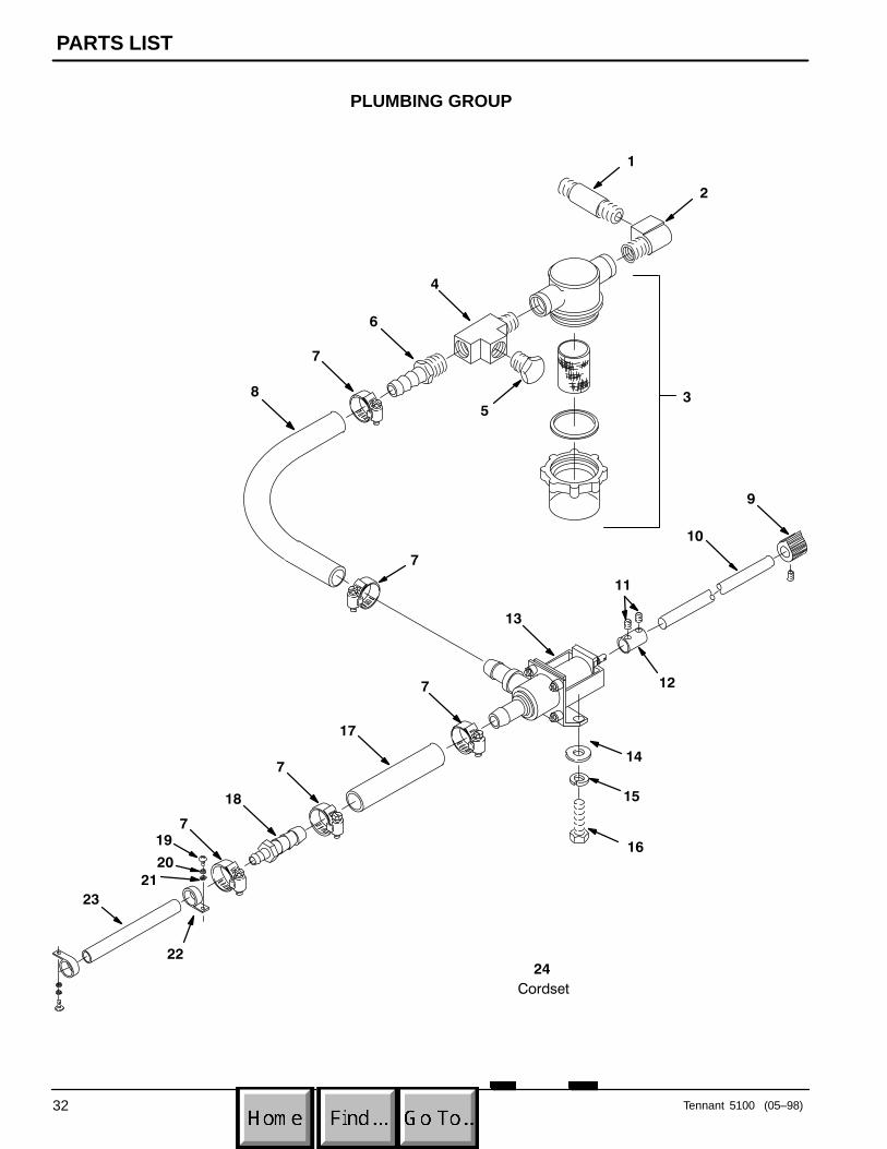
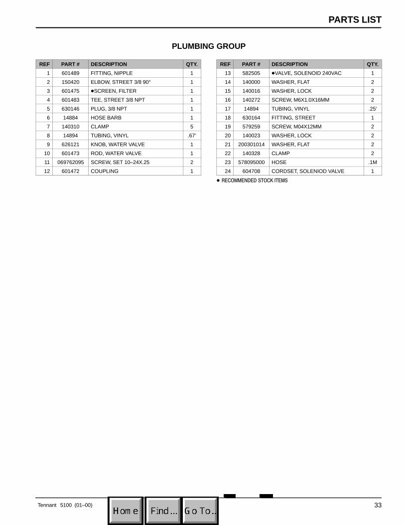
PLUMBING GROUP
REF PART # DESCRIPTION QTY.
1 601489 FITTING, NIPPLE 1
2 150420 ELBOW, STREET 3/8 90° 1
3 601475 �SCREEN, FILTER 1
4 601483 TEE, STREET 3/8 NPT 1
5 630146 PLUG, 3/8 NPT 1
6 14884 HOSE BARB 1
7 140310 CLAMP 5
8 14894 TUBING, VINYL .67’
9 626121 KNOB, WATER VALVE 1
10 601473 ROD, WATER VALVE 1
11 069762095 SCREW, SET 10–24X.25 2
12 601472 COUPLING 1
REF PART # DESCRIPTION QTY.
13 582505 �VALVE, SOLENOID 240VAC 1
14 140000 WASHER, FLAT 2
15 140016 WASHER, LOCK 2
16 140272 SCREW, M6X1.0X16MM 2
17 14894 TUBING, VINYL .25’
18 630164 FITTING, STREET 1
19 579259 SCREW, M04X12MM 2
20 140023 WASHER, LOCK 2
21 200301014 WASHER, FLAT 2
22 140328 CLAMP 2
23 578095000 HOSE .1M
24 604708 CORDSET, SOLENIOD VALVE 1
� RECOMMENDED STOCK ITEMS
PARTS LIST
Tennant 5100 (01–00)34
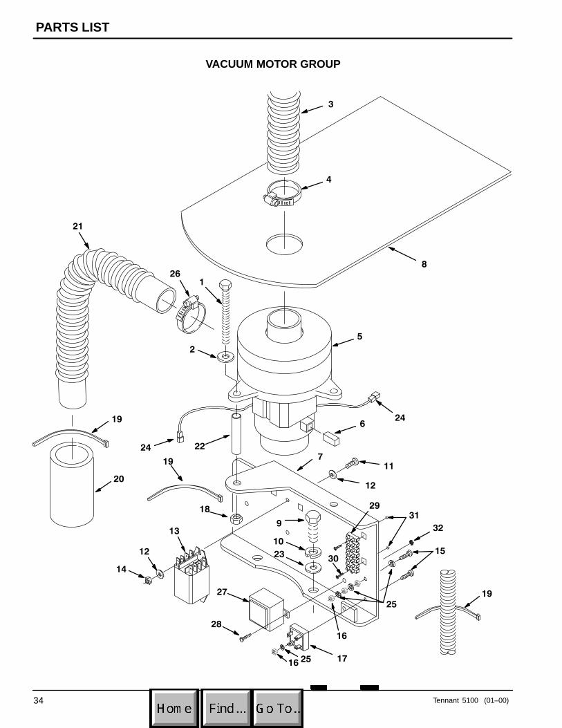
VACUUM MOTOR GROUP
3
4
5
21
261
2
22
19
19
20
9
1013
18
14
6
7
23
24
24
8
11
12
1512
16
1716 25
1925
28
27
31
30
29
32
PARTS LIST
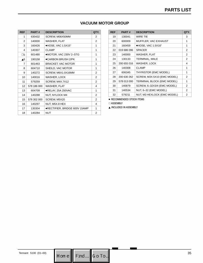
Tennant 5100 (01–00) 35
VACUUM MOTOR GROUP
REF PART # DESCRIPTION QTY.
1 630432 SCREW, M06X50MM 2
2 140000 WASHER, FLAT 2
3 160426 �HOSE, VAC 1.5X15” 1
4 140307 CLAMP 1
∇ 5 601480 �MOTOR, VAC 230V 2–STG 1
�6 190158 �CARBON BRUSH 2/PK 1
7 601463 BRACKET, VAC MOTOR 1
8 604710 SHEILD, VAC MOTOR 1
9 140272 SCREW, M6X1.0X16MM 2
10 140016 WASHER, LOCK 2
11 579259 SCREW, M4X.7X12 2
12 578 186 000 WASHER, FLAT 4
13 604709 �RELAY, 25A 250VAC 1
14 140288 NUT, NYLOCK M4 2
15 578 302 000 SCREW, M5X20 2
16 140297 NUT, M5X.8 HEX 4
17 130304 �RECTIFIER, BRIDGE 600V 15AMP 1
18 140284 NUT 2
REF PART # DESCRIPTION QTY.
19 130041 WIRE TIE 3
20 600009 MUFFLER, VAC EXHAUST 1
21 160459 �HOSE, VAC 1.5X16” 1
22 019 686 096 SPACER 2
23 140000 WASHER, FLAT 2
24 130133 TERMINAL, MALE 2
25 200 655 016 WASHER, LOCK 4
26 140308 CLAMP 1
27 606345 THYRISTOR (EMC MODEL) 1
28 200 630 262 SCREW, M3X.5X10 (EMC MODEL) 2
29 578 013 000 TERMINAL BLOCK (EMC MODEL) 1
30 140879 SCREW, 6–32X3/4 (EMC MODEL) 2
31 140534 NUT, 6–32 (EMC MODEL) 2
32 579211 NUT, M3 HEXLOCK (EMC MODEL) 2
� RECOMMENDED STOCK ITEMS
∇ ASSEMBLY
� INCLUDED IN ASSEMBLY
PARTS LIST
Tennant 5100 (05–98)36
SQUEEGEE GROUP
8
4
3
2
5
7
6
11
12
13
1
9
10
10
4
7
14
15
1617
1819
13
2021
22
2324
25
26
27
2824
29
30
29
PARTS LIST
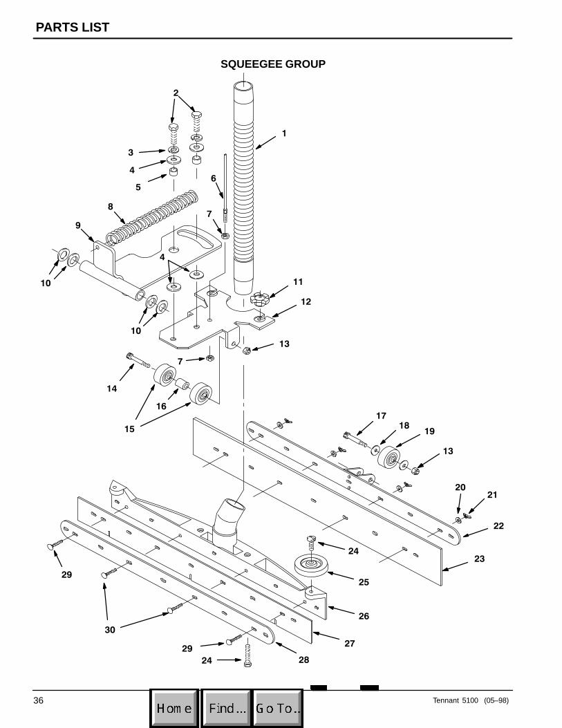
Tennant 5100 (01–00) 37
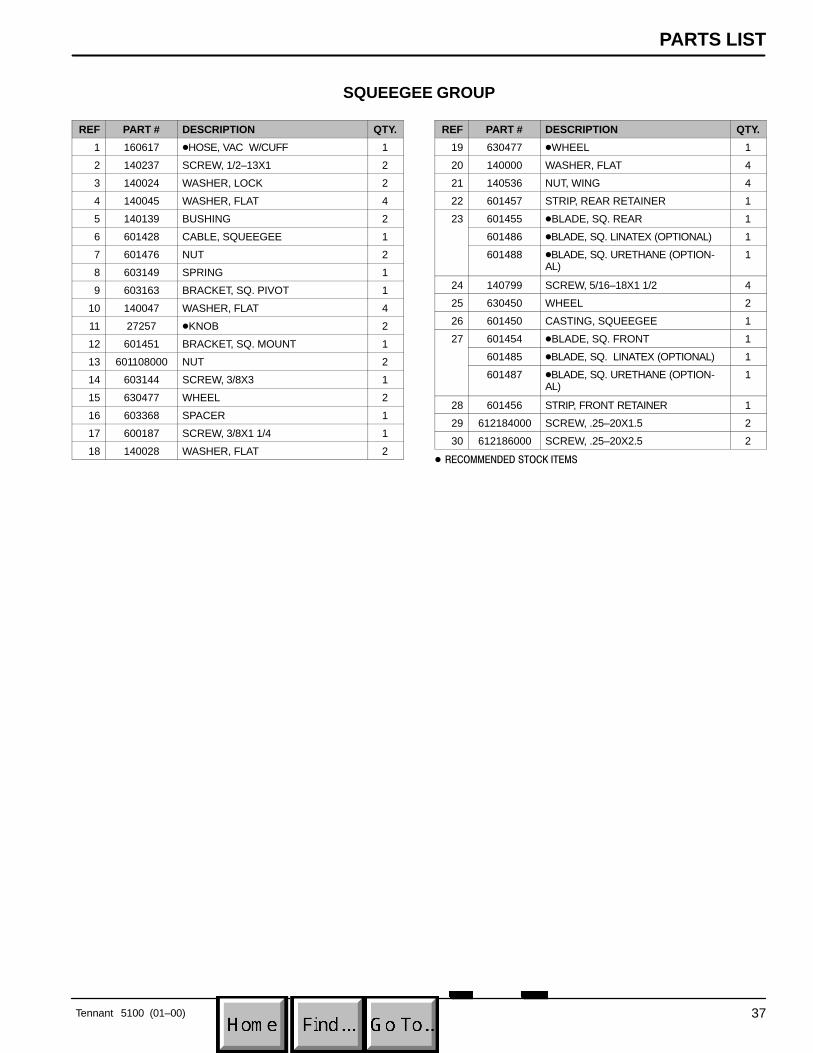
SQUEEGEE GROUP
REF PART # DESCRIPTION QTY.
1 160617 �HOSE, VAC W/CUFF 1
2 140237 SCREW, 1/2–13X1 2
3 140024 WASHER, LOCK 2
4 140045 WASHER, FLAT 4
5 140139 BUSHING 2
6 601428 CABLE, SQUEEGEE 1
7 601476 NUT 2
8 603149 SPRING 1
9 603163 BRACKET, SQ. PIVOT 1
10 140047 WASHER, FLAT 4
11 27257 �KNOB 2
12 601451 BRACKET, SQ. MOUNT 1
13 601108000 NUT 2
14 603144 SCREW, 3/8X3 1
15 630477 WHEEL 2
16 603368 SPACER 1
17 600187 SCREW, 3/8X1 1/4 1
18 140028 WASHER, FLAT 2
REF PART # DESCRIPTION QTY.
19 630477 �WHEEL 1
20 140000 WASHER, FLAT 4
21 140536 NUT, WING 4
22 601457 STRIP, REAR RETAINER 1
23 601455 �BLADE, SQ. REAR 1
601486 �BLADE, SQ. LINATEX (OPTIONAL) 1
601488 �BLADE, SQ. URETHANE (OPTION-AL)
1
24 140799 SCREW, 5/16–18X1 1/2 4
25 630450 WHEEL 2
26 601450 CASTING, SQUEEGEE 1
27 601454 �BLADE, SQ. FRONT 1
601485 �BLADE, SQ. LINATEX (OPTIONAL) 1
601487 �BLADE, SQ. URETHANE (OPTION-AL)
1
28 601456 STRIP, FRONT RETAINER 1
29 612184000 SCREW, .25–20X1.5 2
30 612186000 SCREW, .25–20X2.5 2
� RECOMMENDED STOCK ITEMS

OPTIONS
Tennant 5100 (01–00)38
OPTIONAL KITSREF PART # DESCRIPTION QTY.
603169 �KIT, ES� (EXTENDED SCRUB) 1
603170 �KIT, WAND PUMP 1
REF PART # DESCRIPTION QTY.
603168 �KIT, ES� & WAND PUMP 1
603330 �KIT, HOUR METER 1
ES� KIT
7
1
2
3
4
33
7
6
8
1012 1311
16 1715
18
7
14
19
9
7
2928
3027
31
32
22
21
20
21
25
22
7
25
24
23
26
5
34
35
OPTIONS
Tennant 5100 (01–00) 39
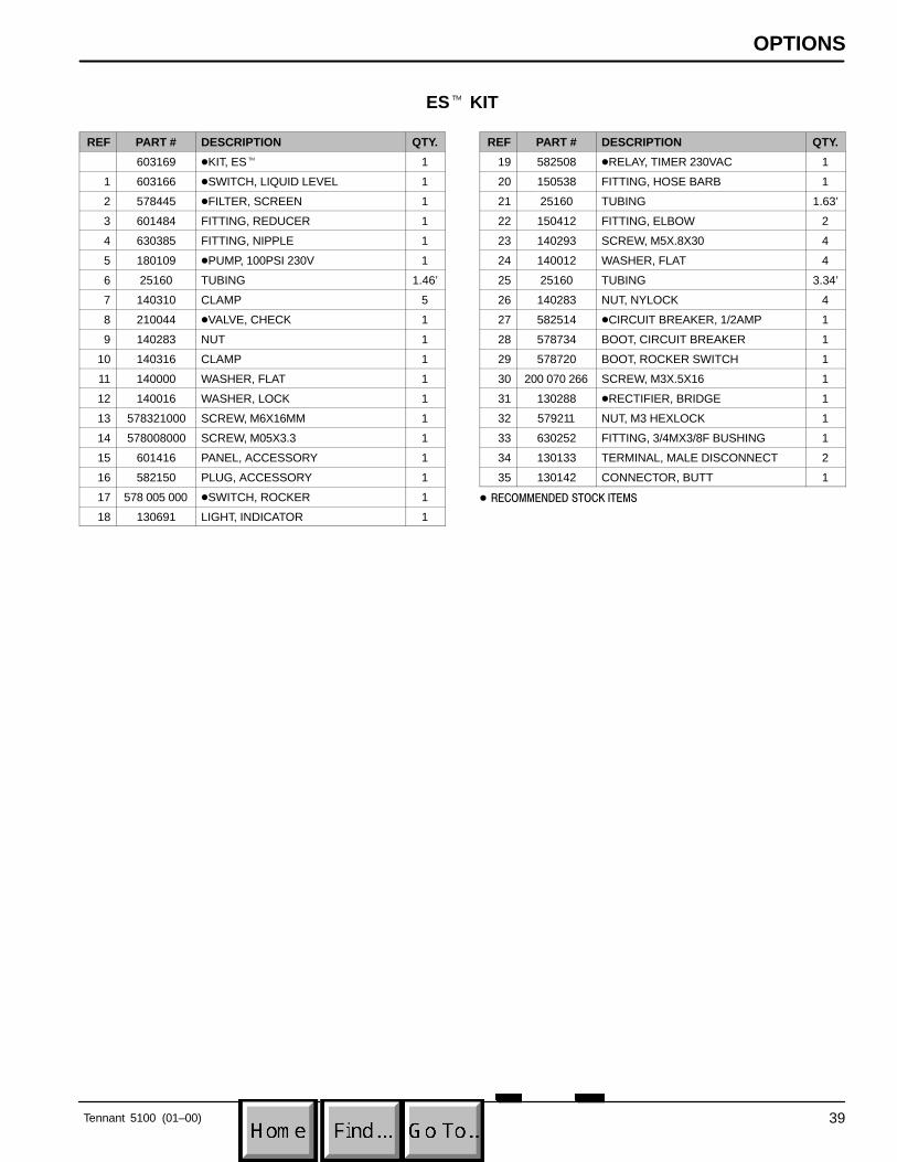
ES� KIT
REF PART # DESCRIPTION QTY.
603169 �KIT, ES� 1
1 603166 �SWITCH, LIQUID LEVEL 1
2 578445 �FILTER, SCREEN 1
3 601484 FITTING, REDUCER 1
4 630385 FITTING, NIPPLE 1
5 180109 �PUMP, 100PSI 230V 1
6 25160 TUBING 1.46’
7 140310 CLAMP 5
8 210044 �VALVE, CHECK 1
9 140283 NUT 1
10 140316 CLAMP 1
11 140000 WASHER, FLAT 1
12 140016 WASHER, LOCK 1
13 578321000 SCREW, M6X16MM 1
14 578008000 SCREW, M05X3.3 1
15 601416 PANEL, ACCESSORY 1
16 582150 PLUG, ACCESSORY 1
17 578 005 000 �SWITCH, ROCKER 1
18 130691 LIGHT, INDICATOR 1
REF PART # DESCRIPTION QTY.
19 582508 �RELAY, TIMER 230VAC 1
20 150538 FITTING, HOSE BARB 1
21 25160 TUBING 1.63’
22 150412 FITTING, ELBOW 2
23 140293 SCREW, M5X.8X30 4
24 140012 WASHER, FLAT 4
25 25160 TUBING 3.34’
26 140283 NUT, NYLOCK 4
27 582514 �CIRCUIT BREAKER, 1/2AMP 1
28 578734 BOOT, CIRCUIT BREAKER 1
29 578720 BOOT, ROCKER SWITCH 1
30 200 070 266 SCREW, M3X.5X16 1
31 130288 �RECTIFIER, BRIDGE 1
32 579211 NUT, M3 HEXLOCK 1
33 630252 FITTING, 3/4MX3/8F BUSHING 1
34 130133 TERMINAL, MALE DISCONNECT 2
35 130142 CONNECTOR, BUTT 1
� RECOMMENDED STOCK ITEMS
OPTIONS
Tennant 5100 (05–98)40
WAND PUMP KIT
6
54
2
3
2
1
13
29
12
11
212
8
7
10
1415
16
17
23
18
22
21
20
19
25
24
OPTIONS
Tennant 5100 (01–00) 41
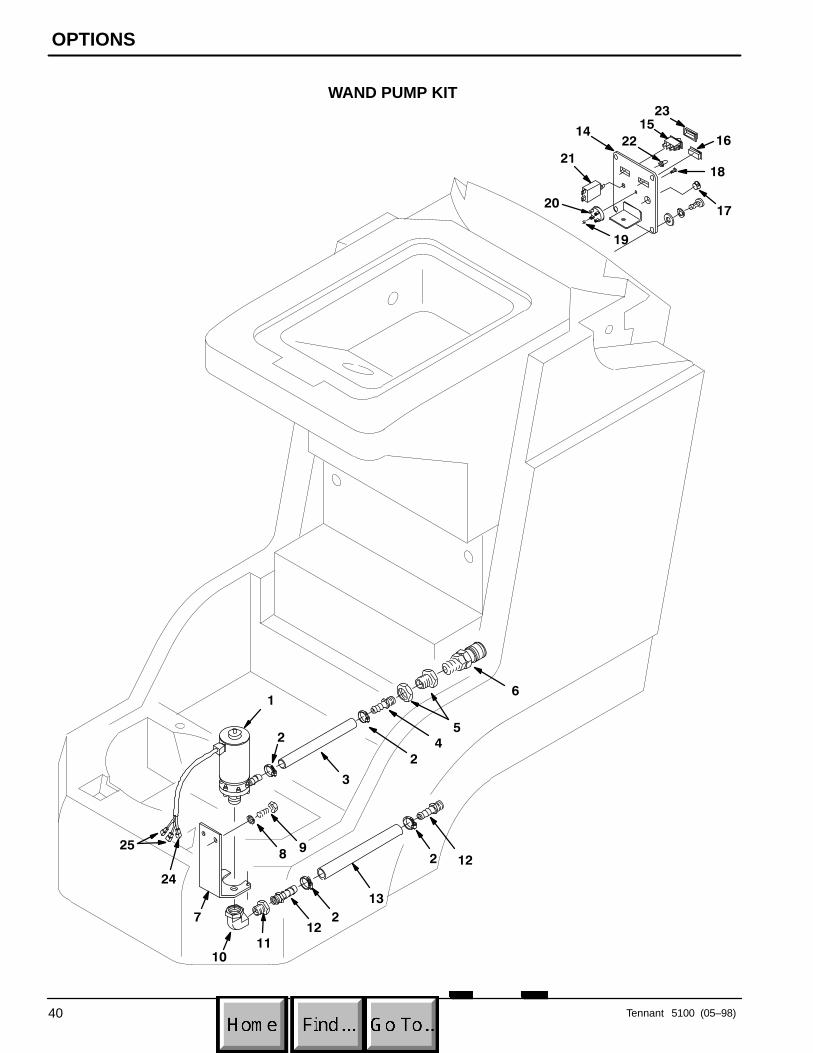
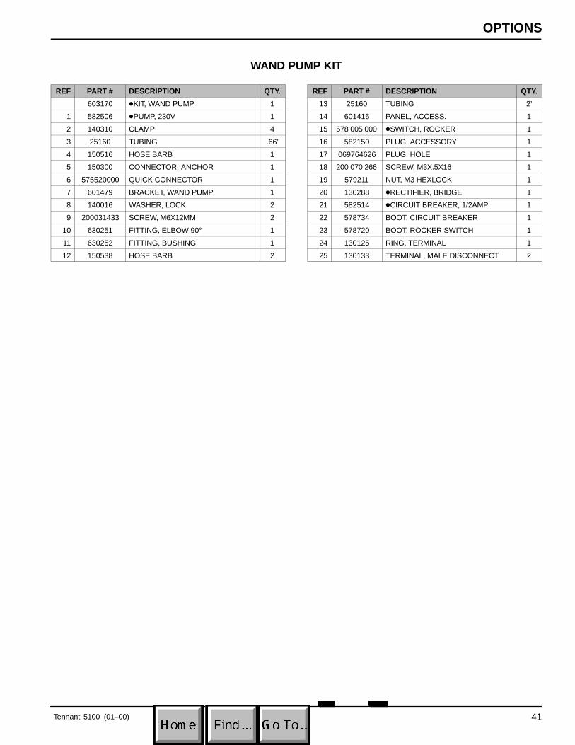
WAND PUMP KIT
REF PART # DESCRIPTION QTY.
603170 �KIT, WAND PUMP 1
1 582506 �PUMP, 230V 1
2 140310 CLAMP 4
3 25160 TUBING .66’
4 150516 HOSE BARB 1
5 150300 CONNECTOR, ANCHOR 1
6 575520000 QUICK CONNECTOR 1
7 601479 BRACKET, WAND PUMP 1
8 140016 WASHER, LOCK 2
9 200031433 SCREW, M6X12MM 2
10 630251 FITTING, ELBOW 90° 1
11 630252 FITTING, BUSHING 1
12 150538 HOSE BARB 2
REF PART # DESCRIPTION QTY.
13 25160 TUBING 2’
14 601416 PANEL, ACCESS. 1
15 578 005 000 �SWITCH, ROCKER 1
16 582150 PLUG, ACCESSORY 1
17 069764626 PLUG, HOLE 1
18 200 070 266 SCREW, M3X.5X16 1
19 579211 NUT, M3 HEXLOCK 1
20 130288 �RECTIFIER, BRIDGE 1
21 582514 �CIRCUIT BREAKER, 1/2AMP 1
22 578734 BOOT, CIRCUIT BREAKER 1
23 578720 BOOT, ROCKER SWITCH 1
24 130125 RING, TERMINAL 1
25 130133 TERMINAL, MALE DISCONNECT 2