Embed Size (px)
Citation preview

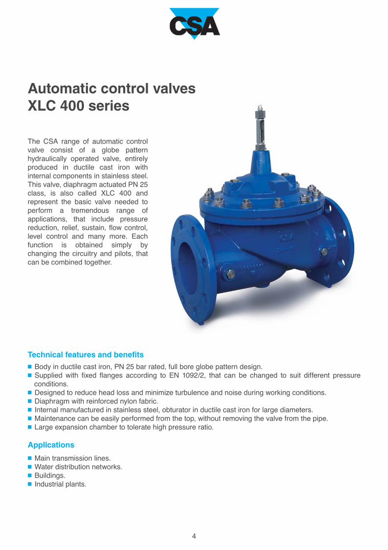
Automatic control valves
XLC 400 series

2
The company was founded in 1987 by transforming the former CSA, which was a trading company dealing
with pipes and valves for water networks, into a manufacturing company, through the research and
realization of pillar fire hydrants. Since then many other products have been added.
The history of our company is characterised by years of technical and commercial research, which have
enabled us to offer a complete range of valves designed for controlling, regulating and protecting the
pipelines under pressure in both waterworks and sewage lines as well as fire hydrants.
Our many industrial patents and innovative technical solutions, together with modern and attractive style of
design, have made it possible to differentiate our products from those offered by competitors and have
allowed us to become a point of reference in our sector.
Flexibility and reliability have been the key points of CSA’s rapid growth over the last few years. We are
perfectly aware that we are managing the world’s most precious resource and, motivated by this
responsibility and the commitment towards our customers, we have dedicated ourselves to constantly
improving our products, placing them at the highest levels of quality.
Quality
In the manufacturing business today, quality is the
fundamental requirement for achieving and main-
taining a growing market share.
For this reason we have always aimed at developing
a synergy between the various sectors of the com-
pany and thus ensuring:
-quick and precise answers;
-evaluation of data received and immediate re-
sponse;
-rigorous control of incoming and outgoing products.
Since 1998 CSA is certified according to regulation
ISO 9001 by RINA (Italian Naval Registry) recently
converted into ISO 9001/2008.
3
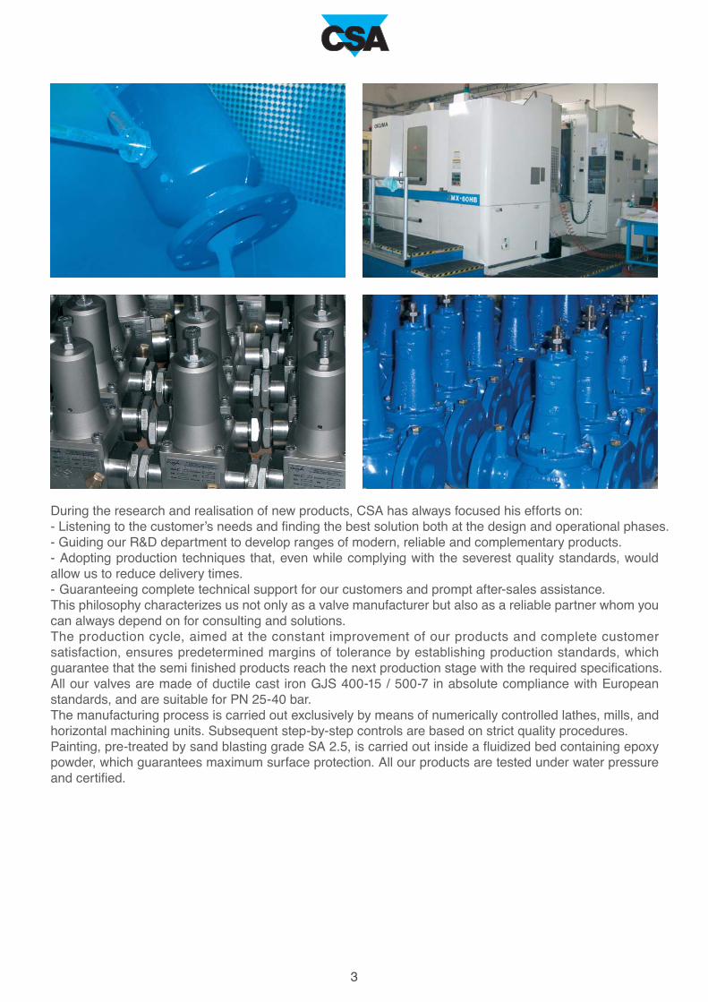
During the research and realisation of new products, CSA has always focused his efforts on:
- Listening to the customer’s needs and finding the best solution both at the design and operational phases.
- Guiding our R&D department to develop ranges of modern, reliable and complementary products.
- Adopting production techniques that, even while complying with the severest quality standards, would
allow us to reduce delivery times.
- Guaranteeing complete technical support for our customers and prompt after-sales assistance.
This philosophy characterizes us not only as a valve manufacturer but also as a reliable partner whom you
can always depend on for consulting and solutions.
The production cycle, aimed at the constant improvement of our products and complete customer
satisfaction, ensures predetermined margins of tolerance by establishing production standards, which
guarantee that the semi finished products reach the next production stage with the required specifications.
All our valves are made of ductile cast iron GJS 400-15 / 500-7 in absolute compliance with European
standards, and are suitable for PN 25-40 bar.
The manufacturing process is carried out exclusively by means of numerically controlled lathes, mills, and
horizontal machining units. Subsequent step-by-step controls are based on strict quality procedures.
Painting, pre-treated by sand blasting grade SA 2.5, is carried out inside a fluidized bed containing epoxy
powder, which guarantees maximum surface protection. All our products are tested under water pressure
and certified.
4
Automatic control valves XLC 400 series
The CSA range of automatic control
valve consist of a globe pattern
hydraulically operated valve, entirely
produced in ductile cast iron with
internal components in stainless steel.
This valve, diaphragm actuated PN 25
class, is also called XLC 400 and
represent the basic valve needed to
perform a tremendous range of
applications, that include pressure
reduction, relief, sustain, flow control,
level control and many more. Each
function is obtained simply by
changing the circuitry and pilots, that
can be combined together.
Technical features and benefits
Body in ductile cast iron, PN 25 bar rated, full bore globe pattern design.
Supplied with fixed flanges according to EN 1092/2, that can be changed to suit different pressure
conditions.
Designed to reduce head loss and minimize turbulence and noise during working conditions.
Diaphragm with reinforced nylon fabric.
Internal manufactured in stainless steel, obturator in ductile cast iron for large diameters.
Maintenance can be easily performed from the top, without removing the valve from the pipe.
Large expansion chamber to tolerate high pressure ratio.
Applications
Main transmission lines.
Water distribution networks.
Buildings.
Industrial plants.

1
2
1A
2A
5
The standard version of mobile block and sealing seat, depicted above, includes the obturator, diaphragm
and a special gasket holder designed to guarantee the maximum accuracy also during the low opening of
the valve. The mobile block with this version is guided in two points, on the cap and on the seat.
The AC system is obtained by means of a special seat and device which improves the guiding of the entire
block, yet increasing the allowable pressure ratio and valve’s performances, also in case of low flow rate
avoiding vibrations and noise.
Body in ductile cast iron
Upper flat in painted steel/stainless steel
Spring in stainless steel
Position indicator in stainless steel or brass
Seat in stainless steel
Gasket holder in stainless steel
Shaft in stainless steel
1. Gasket holder in stainless steel
2. Seat in stainless steel
1. Anti-cavitation V-port
2. Seat in stainless steel for anti-cavitation system
Diaphragm in neoprene nylon reinforced
Technical features
Standard version of mobile block and sealing seat
AC version for low flow stability and cavitation prevention

6
Operating principle on-off mode
Operating principle modulating mode
Valve opening
When the valve is set to modulate a
restriction is required between the
upstream pressure and control
chamber, in addition to a modulat-
ing device as shown in the picture.
If the latter is entirely open the pres-
sure inside the control chamber will
be relieved, allowing for the com-
plete opening of the valve.
Valve modulating
During working conditions if the
modulating device is throttled,
reducing the flow passage through
it, pressure will be applied inside the
control chamber making the valve’s
mobile block reacting accordingly
on the main valve XLC 400.
Valve closing
I f the modulat ing dev ice is
completely closed, all the upstream
pressure will be diverted into the
control chamber. The mobile block
will therefore be pushed down on
the obturator, producing the inter-
ruption of flow through the XLC 400.
Valve opening
If the pressure inside the control
chamber is put in communication
with the atmosphere the entire
upstream pressure will act on the
obturator, pushing it upwards
allowing the complete opening of
the valve.
Valve modulating
During working conditions if the
control chamber is isolated from the
upstream pressure the valve will
remain in the same posit ion,
therefore producing the head loss
corresponding to such opening
percentage.
Valve closing
If the control chamber is put in com-
munication with the upstream pres-
sure, thanks to the difference in
area between the upper flat with
diaphragm, larger that the obturator
underneath, the valve will close
completely.

1
2
3
4
5
6
7
8
9
7
The unit flow control “GR.I.F.O.” is a device, designed for modulation, that includes all the necessary
functions required for the proper operation of CSA control valves. Entirely built in stainless steel, its
compact design makes the circuit easy to be maintained and at the same time allows for a tremendous
range of regulations.
GR.I.F.O. is composed of the following:
- a filter, with fine mesh in stainless steel AISI 316, to protect the hydraulic circuitry from possible dirt;
- three needles in stainless steel with check valves, responsible for the regulation of the main valve’s
response time, opening and closing speed independently from each other;
- filtered and unfiltered pressure ports.
Valve opening
If the downstream pressure value
becomes lower than the pilot’s set
point the passage through the latter
will increase, thus relieving pres-
sure out of the main valve chamber
XLC 400 with consequent opening
as shown in the picture above.
Valve modulating
As a consequence of gradual
change and variation in demands
the pilot will keep adjusting, this is
to regulate the flow in and out of the
main chamber. The XLC 400 will
then follow the movements of the
pilot producing the necessary
head-loss required for the down-
stream pressure reduction.
Valve closing
If the downstream pressure value
becomes higher than the pilot’s set
point the passage through the pilot
will decrease, thus conveying flow
and pressure to the main chamber
of the XLC 400 valve with conse-
quent closure as shown in the
picture above.
GR.I.F.O. 3/8G PN 25
Operating principle modulating mode - pressure reduction
1. Closing speed regulation
2. Opening speed regulation
3. Adjustable orifice regulation
4. Unfiltered 1/8 G port
5. 3/8 G port
6. 3/8 G port
7. 3/8 G port
8. Filtered 1/8 G port
9. Filter

8
Installation layoutThe picture depicted below shows the recommended installation layout of the CSA XLC 410.
The sectioning devices and by-pass are very important for maintenance operations, as well as the filter to
prevent dirt from reaching the control valve. The direct acting pressure reducer CSA Mod. VRCD is the best
choice on the by-pass due to long periods of inactivity. A pressure relief, CSA model VSM or XLC 420,
must be present to prevent under any circumstances rise in pressure on the downstream line.
The CSA XLC 410 control valve will reduce and
stabilize the downstream pressure to a preset
value, regardless of variations in demand and
upstream pressure fluctuations.
Most popular configurations
XLC 410-FR
XLC 410-ND
XLC 412
XLC 415
downstream pressure reducing with back-
flow prevention
downstream pressure reducing stabilizing
valve with programmer and two set points
downstream pressure reducing and up-
stream pressure sustaining valve
downstream pressure reducing stabilizing
valve with solenoid control
Downstream pressure
reducing stabilizing valve
Mod. XLC 410

9
Pressure management
valve
Mod. XLC 410-T
The CSA XLC 410-T pressure reducing valve,
working in combination with a controller, will auto-
matically maintain and reduce the downstream
pressure either at the valve location or at the
critical point according to the flow rate variations,
whose values are preset and adjustable all the
time with a dedicated web interface.
Installation layoutThe picture below shows the recommended installation layout of XLC 410-T, showing the valve and the
controller along with flow measurement and pressure measurement devices, necessary for the data
acquisition and working principle. A by-pass with CSA XLC 410, air valves and pressure relief valve are
also recommended for better performances and reliability of the system.

10
The CSA XLC 420 control valve will sustain, if
installed in-line, and relief if installed in derivation
from the main line, the upstream pressure to a
pre-set value regardless of variations in demand.
Upstream pressure
sustaining-relief valve
Mod. XLC 420
Installation layoutThe picture depicted below shows the recommended installation layout of the CSA XLC 420, used as a
pressure relief in derivation from the main line to protect a pumping station. The sectioning device is very
important for maintenance operations, whenever possible a filter too is needed to prevent dirt from
reaching the control valve. The set point should always remain within 0,5-1 bar above the maximum steady
state pressure value of the pumps.
Most popular configurations
XLC 420-FR
XLC 421
XLC 424
XLC 425
upstream pressure relief/sustaining valve
with back-flow prevention
upstream pressure relief surge anticipating
control valve
combination of upstream pressure sustain-
ing and min.-max. level control valve
upstream pressure sustaining-relief valve
with solenoid control

11
Most popular configurations
XLC 431
XLC 434
XLC 435
pressure reducing flow control valve
flow control valve with minimum-maximum
level control
flow control valve with solenoid control
Flow rate automatic
control valve
Mod. XLC 430
The CSA XLC 430 flow control valve will
automatically limit the flow to a preset value,
regardless of pressure variations. In case of flow
rate lower than the required set point the valve will
be fully opened. For the proper installation the
flanged orifice, supplied with the valve, must be
installed at least 5 DN downstream.
Installation layoutThe picture below shows the recommended layout of the CSA XLC 430, flow control valve. The flange
orifice, calculated and machined according to the project’s requirements, is linked to the valve’s pilot and
has to be installed 5 DN downstream for the best performance and accuracy. The variation on the flow rate
set point value, obtained by adjusting the pilot, is ±32%.

12
Most popular configurations
XLC 440-FR
XLC 445
minimum-maximum level control valve with
back-flow prevention system
minimum-maximum level with solenoid
control valve
Minimum-Maximum
level control valve
Mod. XLC 440
The CSA XLC 440 minimum-maximum level
control valve will automatically operate a on-off
regulation to maintain the tank level within an
adjustable range, going from approximately 15 cm
up to 4 m. Thanks to a CSA needle valve the
reaction time can be adjusted, to prevent water
hammer effects during the closing phase.
Installation layoutThe picture below shows the recommended layout of the CSA XLC 440, minimum-maximum level control
valve. The connection between the valve and the pilot is obtained by means of two pipes, one linked to the
upstream pressure and the other to the chamber. The stilling tank allows for the proper control without
accessing directly to the tank. The valve is supplied with the CSA minimum-maximum pilot system
adjustable with a range between 0,15 and 4 m.

13
On-off solenoid
control valve
Mod. XLC 450
The CSA XLC 450 solenoid control valve will
either open or close in response to a signal from
remote or by an external controller. Thanks to a
CSA needle valve the reaction time can be
adjusted, to prevent water hammer effects during
the closing phase.
Most popular configurations
XLC 450-P
Installation layoutThe solenoid control valve XLC 450 can be used whenever the on-off regulation is needed, the impulse is
received by external equipments, sensors. The picture below shows a way of using CSA XLC 450 to
control the tank in connection with a switch, sensing the level variation. The valve is usually supplied with
the manual opening and closing circuit, to allow for regulations even in case of power failure.
on-off solenoid control valve with battery
operated programmer

14
Step by step solenoid
control valve
Mod. XLC 453
The CSA XLC 453 step by step solenoid control
valve, usually installed in combination with a PLC
or managed directly from the remote monitoring
system, will perform a regulation in response to
the signals sent to the solenoid valves. Thanks to
a CSA needle valve, the reaction time can be
adjusted to prevent water hammer effects, during
the modulating/closing phase. The valve, as
shown in the picture, can be supplied with an
additional circuit for emergency situations of
manual opening and closing.
Installation layoutThe picture below shows the CSA XLC 453 installed in combination with a flow meter and linked to CSA
PLC. The latter will constantly send impulses to the valve’s solenoids to make it throttle as required. The
purpose is to maintain the same flow regardless of pressure variations, or obtain a pressure management
function according to variations in demand to reduce water loss and leakage. Another common application
of XLC 453 is to regulate the water level of tanks, where the PLC is connected to sensors.

15
Constant level
control valve
Mod. XLC 460
The CSA XLC 460 constant level control valve will
automatically maintain the tank level within a
range of approximately 15 cm. Thanks to a CSA
needle valve the reaction time can be adjusted, to
prevent water hammer effects during the closing
phase. It is important to follow the instructions
enclosed in the set up and installation manual, for
the proper layout and minimum pressure required.
Installation layoutThe picture below shows the recommended installation layout of XLC 460, linked to the pilot through a
single pipe, two pipes in case of the version with stainless steel pilots. The filter is always needed upstream
to prevent dirt from entering the main valve, affecting the performance. A minimum pressure of 0,4 bar is
always needed on the pilot to make the valve work properly.
Most popular configurations
XLC 426
XLC 460-
rotoway
XLC 465
upstream pressure sustaining level control
valve
constant level control valve with stainless
steel pilot
constant level control valve with on-off
solenoid control

16
High sensitivity altitude
control valve
Mod. XLC 470
The CSA XLC 470 altitude control valve will
maintain the level of a water tower or a tank,
regardless of upstream pressure variations, acting
with an accuracy of few cm of water column.
The modulating control ensures a smooth
regulation and absence of water hammer, as the
valve will react proportionally to the variations in
demand.
Installation layoutThe picture below shows the recommended installation layout of XLC 470, where the control is obtained
without any external piping and simply through a pilot sensing the static pressure coming from the water
tower. A minimum of 1,8 meters static pressure, in addition to head loss during valve’s opening, will
be needed to make this model work properly.
Most popular configurations
XLC 427
XLC 470-FR
XLC 475
upstream pressure sustaining altitude
control valve
altitude control valve with back-flow
prevention mechanism
altitude valve with on-off solenoid control

17
Excess flow automatic
control valve
Mod. XLC 480
The CSA XLC 480 burst contro l va lve,
hydraulically operated without any other auxiliary
device, will sense an excess in flow diverting the
upstream pressure to the main control chamber,
and causing a complete closure, to be manually
reset after that. As long as the flow rate remains
below the set point, preset and adjustable, the
valve will remain fully open minimizing head loss.
Installation layoutThe valve XLC 480 may cause pressure surge upon closure depending on the location, fluid velocity,
differential pressure. A pressure relief valve installed upstream, CSA mod. VSM or fast acting VRCA is
therefore recommended, along with a pressure sustaining valve CSA mod. XLC 420 or VSM on the
by-pass line during maintenance operation. CSA anti hammer air valves mod. FOX 3F RFP are also
needed for air control and water hammer protection during the valve closure and the pipe filling.
Most popular configurations
XLC 481
XLC 480-FR
XLC 485
burst control and pressure reducing valve
burst flow and flow prevention mechanism
burst flow and solenoid control valve
18
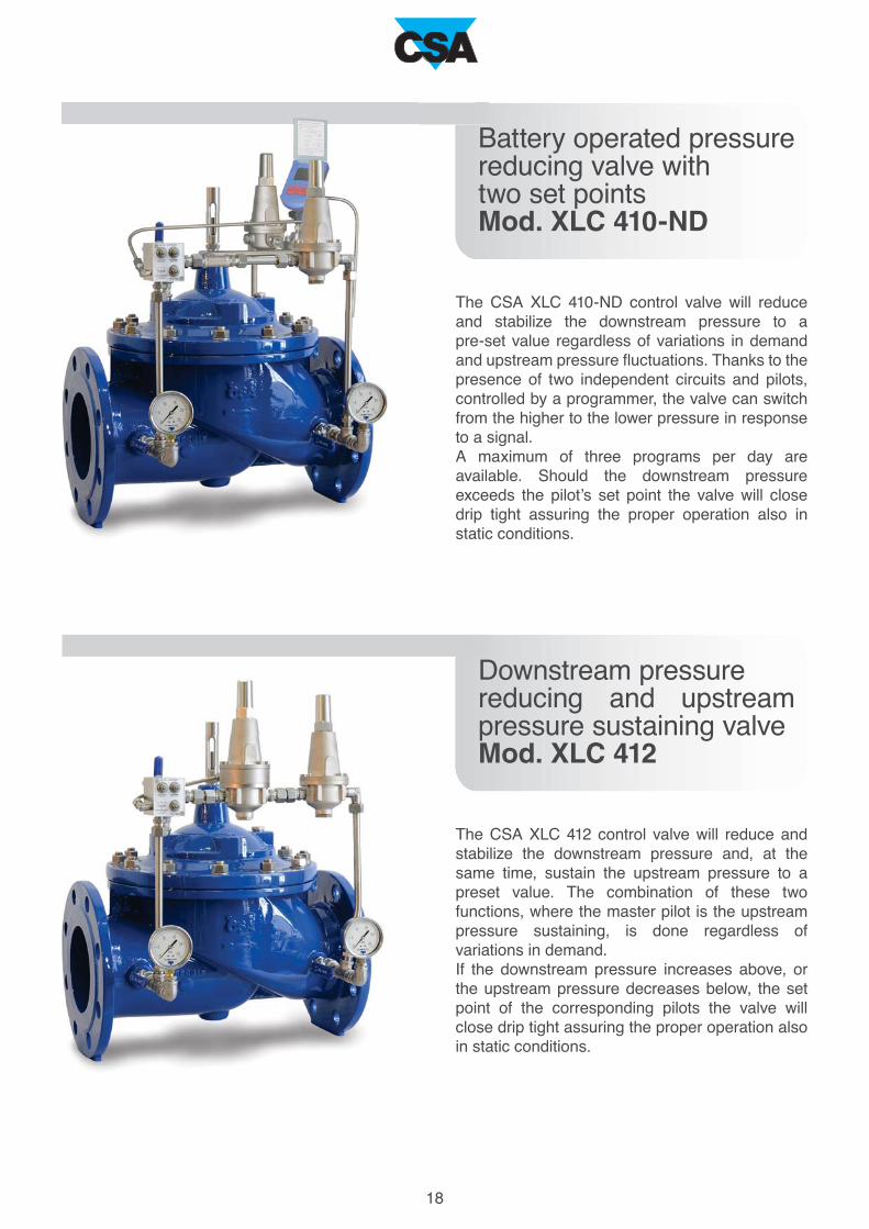
Battery operated pressure
reducing valve with
two set points
Mod. XLC 410-ND
The CSA XLC 410-ND control valve will reduce
and stabilize the downstream pressure to a
pre-set value regardless of variations in demand
and upstream pressure fluctuations. Thanks to the
presence of two independent circuits and pilots,
controlled by a programmer, the valve can switch
from the higher to the lower pressure in response
to a signal.
A maximum of three programs per day are
available. Should the downstream pressure
exceeds the pilot’s set point the valve will close
drip tight assuring the proper operation also in
static conditions.
Downstream pressure
reducing and upstream
pressure sustaining valve
Mod. XLC 412
The CSA XLC 412 control valve will reduce and
stabilize the downstream pressure and, at the
same time, sustain the upstream pressure to a
preset value. The combination of these two
functions, where the master pilot is the upstream
pressure sustaining, is done regardless of
variations in demand.
If the downstream pressure increases above, or
the upstream pressure decreases below, the set
point of the corresponding pilots the valve will
close drip tight assuring the proper operation also
in static conditions.

19
Downstream pressure
reducing stabilizing valve
with solenoid control
Mod. XLC 415
The CSA XLC 415 control valve will reduce and
stabilize the downstream pressure to a preset
value regardless of variations in demand and
upstream pressure fluctuations. Thanks to a
solenoid the valve will be able to open or close
completely, in response to a signal sent from
remote or by a controller. Should the downstream
pressure exceeds the pilot’s set point the valve will
close drip tight, assuring the proper operation also
in static conditions.
Upstream pressure relief
surge anticipating
control valve
Mod. XLC 421
The CSA XLC 421 control valve, installed in
derivation from the main line, will act as a
pressure relief of the upstream pressure. Thanks
to another pilot, in case of pump failure the valve
will sense the drop in pressure and, as a
consequence of that, the chamber will be put in
communication with the atmosphere, before the
rise in pressure coming from the second phase of
the transient. For the proper sizing and water
hammer analysis please contact CSA.
20
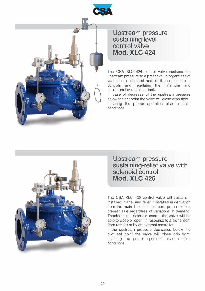
Upstream pressure
sustaining level
control valve
Mod. XLC 424
The CSA XLC 424 control valve sustains the
upstream pressure to a preset value regardless of
variations in demand and, at the same time, it
controls and regulates the minimum and
maximum level inside a tank.
In case of decrease of the upstream pressure
below the set point the valve will close drop-tight
ensuring the proper operation also in static
conditions.
Upstream pressure
sustaining-relief valve with
solenoid control
Mod. XLC 425
The CSA XLC 425 control valve will sustain, if
installed in-line, and relief if installed in derivation
from the main line, the upstream pressure to a
preset value regardless of variations in demand.
Thanks to the solenoid control the valve will be
able to close or open, in response to a signal sent
from remote or by an external controller.
If the upstream pressure decreases below the
pilot set point the valve will close drip tight,
assuring the proper operation also in static
conditions.

21
Pressure reducing
flow automatic
control valve
Mod. XLC 431
The CSA XLC 431 pressure reducing flow control
valve automatically reduces and stabilizes the
downstream pressure to a preset value and, at
the same time, it limits the flow to a requested
set point, regardless of pressure variations. If
the downstream pressure rises above the
downstream pilot setting, the valve will close
drop tight to ensure the proper operation also
in static conditions. For the proper installation
the flanged orifice, supplied with the valve, must
be installed at least 5 DN downstream.
Flow control valve with
minimum-maximum
level control
Mod. XLC 434
The CSA XLC 434 level regulation flow control
valve limits the flow to a requested set point,
regardless of pressure variations. At the same
time, thanks to a three ways on-off level control
pilot CSA mod. Rotoway, she controls the
minimum-maximum level inside a tank.
During the opening phase of the pilot, in case
of flow rate lower than the set point the valve
will be fully opened. For the proper installation
the flanged orifice, supplied with the valve, must
be placed at least 5 DN downstream.
Please consult CSA technical support for the
proper sizing and minimum pressure needed to
ensure the best performance of this valve.
22
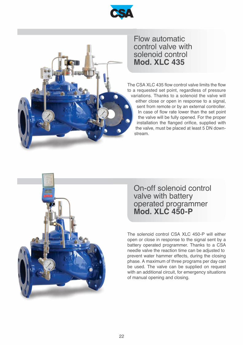
Flow automatic
control valve with
solenoid control
Mod. XLC 435
The CSA XLC 435 flow control valve limits the flow
to a requested set point, regardless of pressure
variations. Thanks to a solenoid the valve will
either close or open in response to a signal,
sent from remote or by an external controller.
In case of flow rate lower than the set point
the valve will be fully opened. For the proper
installation the flanged orifice, supplied with
the valve, must be placed at least 5 DN down-
stream.
On-off solenoid control
valve with battery
operated programmer
Mod. XLC 450-P
The solenoid control CSA XLC 450-P will either
open or close in response to the signal sent by a
battery operated programmer. Thanks to a CSA
needle valve the reaction time can be adjusted to
prevent water hammer effects, during the closing
phase. A maximum of three programs per day can
be used. The valve can be supplied on request
with an additional circuit, for emergency situations
of manual opening and closing.

23
Constant level control
valve with on-off
solenoid control
Mod. XLC 465
The CSA XLC 465 constant level control
valve automatically maintains the tank
level within a range of approximately 15 cm,
and in combination with a solenoid, also enables a
on-off control in response to a signal from remote
or by a controller. Thanks to a CSA needle valve
the reaction time can be adjusted, to prevent water
hammer effects during the closing phase. It is
important to follow the instructions enclosed in the
set up and installation manual for the proper layout
and minimum pressure required.
Constant level
automatic
control valve
Mod. XLC 460 - rotoway
The CSA XLC 460-rotoway constant level control
valve will automatically maintain the tank level
within a range of approximately 15 cm, by means
of a three ways pilot entirely built in stainless steel.
Thanks to a CSA needle valve the reaction time
can be adjusted to prevent water hammer effects
during the closing phase. It is important to follow
the instructions enclosed in the set up and
installation manual, for the proper layout and
minimum pressure required.

200 m
m
81 mm
1
2
3
4
5
6
7
8
9
10
11
12
13
14
15
16
17
5
4
3
6
17
10
1
14
7
16
2
9
11
12
13
8
15
N.
24
The Microstab MRV model is a two ways direct acting downstream pressure reducing-stabilizing valve. Diaphragm operated, the
MRV will maintain an outlet pressure, preset and adjustable, to a fixed value regardless of variation of the upstream pressure and
demand. This product is normally used for the regulation of XLC 400 and 300 series and, due to its high sensitivity and accuracy,
materials and long lasting performances, as a stand-alone for water distribution systems, industrial installation, buildings.
Supplied with a wide choice of optional materials and spring range, MRV is available with the PN 16 and 25 bar versions.
Direct acting pressure reducing-stabilizing valve Mod. Microstab MRV
Body
Cover
Hood
Regulating screw
Nut
Spring guide
Spring
Self-locking nut
Upper flat
Diaphragm
Obturator holder
Sealing seat
Gasket holder
Plane gasket
Tap
O-ring
Screw
nickel-plated bronze/st. steel
nickel-plated bronze/st. steel
stainless steel
stainless steel
stainless steel
stainless steel
painted steel 52SiCrNi5/st. st.
stainless steel
stainless steel
neoprene
stainless steel
stainless steel
stainless steel
NBR
stainless steel
NBR
stainless steel
The list of materials and components is subject to changes without notice.
Spring
blue
red
Higher values available on request.
Pressure range [bar]
0,7 - 7
1,5 - 15
Design and testing in accordance with EN 1074.
Treated water maximum 70°C.
Minimum pressure : 0,5 bar in
addition to head loss.
Maximum pressure: 25 bar.
Kv equal to 0,82 m3/h.
Recommended flow rate: 0,5 m3/h.
Weight 1,55 Kg.
Normally supplied with 3/8" F.
Component Material
Downstream pressure adjustment
Standard
Working conditions Technical data

225 m
m
81 mm
1
2
3
4
5
6
7
8
9
10
11
12
13
14
15
16
17
18
19
20
21
22
23
24
6
5
8
3
9
10
15
19
1
11
22
24
17
18
16
20
21
14
2
12
7
13
4
23
N.
25
The Microstab MSM model is a two ways direct acting upstream pressure sustaining-relief valve. Diaphragm operated, the MSM
will maintain an inlet pressure, preset and adjustable, to a fixed value regardless of variation of the downstream pressure and
demand. This product is normally used for the regulation of XLC 400 and 300 series and, due to its high sensitivity and accuracy,
materials and long lasting performances, as a stand-alone unit for water distribution systems, industrial installation, buildings.
Supplied with a wide choice of optional materials and spring range, MSM is available with the PN 16 and 25 bar versions.
Direct acting pressure sustaining-relief valveMod. Microstab MSM
Body
Cover
Hood
Regulating screw
Nut
Spring guide
Spring
Self-locking nut
Upper flat
Diaphragm
Diaphragm lower disk
O-ring
Shaft
O-ring
Intermediate body
O-ring
Gasket container
Gasket
Screw
Sealing seat
Tap
Tap
O-ring
Screws
nickel-plated bronze/st. steel
nickel-plated bronze/st. steel
stainless steel
stainless steel
stainless steel
stainless steel
painted steel 52SiCrNi5/st. st.
stainless steel
stainless steel
neoprene
stainless steel
NBR
stainless steel
NBR
stainless steel
NBR
stainless steel
NBR
stainless steel
stainless steel
stainless steel
stainless steel
NBR
stainless steel
The list of materials and components is subject to changes without notice.
Spring
blue
red
Higher values available on request.
Pressure range [bar]
0,7 - 7
1,5 - 15
Treated water maximum 70°C.
Minimum pressure : 0,5 bar in
addition to head loss.
Maximum pressure: 25 bar.
Design and testing in accordance with EN 1074.
Kv equal to 0,9 m3/h.
Recommended flow rate: 0,5 m3/h.
Weight 2,23 Kg.
Normally supplied with 3/8" F.
Component Material
Upstream pressure adjustment
Standard
Working conditions Technical data
215 m
m
90 mm
1
2
3
4
5
6
7
8
9
10
11
12
13
14
15
16
17
18
19
20
6
5
3
9
10
15
19
1
11
20
16
18
17
14
2
12
8
7
13
4
N.
26
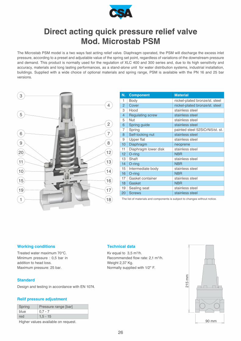
The Microstab PSM model is a two ways fast acting relief valve. Diaphragm operated, the PSM will discharge the excess inlet
pressure, according to a preset and adjustable value of the spring set point, regardless of variations of the downstream pressure
and demand. This product is normally used for the regulation of XLC 400 and 300 series and, due to its high sensitivity and
accuracy, materials and long lasting performances, as a stand-alone unit for water distribution systems, industrial installation,
buildings. Supplied with a wide choice of optional materials and spring range, PSM is available with the PN 16 and 25 bar
versions.
Direct acting quick pressure relief valveMod. Microstab PSM
Body
Cover
Hood
Regulating screw
Nut
Spring guide
Spring
Self-locking nut
Upper flat
Diaphragm
Diaphragm lower disk
O-ring
Shaft
O-ring
Intermediate body
O-ring
Gasket container
Gasket
Sealing seat
Screws
nickel-plated bronze/st. steel
nickel-plated bronze/st. steel
stainless steel
stainless steel
stainless steel
stainless steel
painted steel 52SiCrNi5/st. st.
stainless steel
stainless steel
neoprene
stainless steel
NBR
stainless steel
NBR
stainless steel
NBR
stainless steel
NBR
stainless steel
stainless steel
The list of materials and components is subject to changes without notice.
Spring
blue
red
Higher values available on request.
Pressure range [bar]
0,7 - 7
1,5 - 15
Treated water maximum 70°C.
Minimum pressure : 0,5 bar in
addition to head loss.
Maximum pressure: 25 bar.
Design and testing in accordance with EN 1074.
Kv equal to 3,5 m3/h.
Recommended flow rate: 2,1 m3/h.
Weight 2,37 Kg.
Normally supplied with 1/2" F.
Component Material
Relif pressure adjustment
Standard
Working conditions Technical data

1
2
3
4
5
6
7
8
9
10
11
12
13
14
15
16
17
18
19
20
21
N.
19
5 18
4
3
20
17
10
1
14
7
16
2
9
11
12
13
8
6
21
15
200 m
m
81 mm
27
The Microstab MLP model is a two ways direct acting flow control valve. Diaphragm operated, the MLP will limit the maximum
flow rate, preset and adjustable, to a fixed value regardless of upstream pressure variations. This product is normally used for the
regulation of XLC 400 and 300 series and, due to its high sensitivity and accuracy, materials and long lasting performances, as
a stand-alone unit for water distribution systems, industrial installation, buildings. Supplied with a wide choice of optional
materials, and available with the PN 16 and 25 bar version, MLP is provided with a flow rate regulation chart for on-site
adjustments according to the compression of the spring.
Flow control valveMod. Microstab MLP
The list of materials and components is subject to changes without notice.
Treated water maximum 70°C.
Minimum pressure : 0,5 bar in
addition to head loss.
Maximum pressure: 25 bar.
Design and testing in accordance with EN 1074.
Component Material
Body
Cover
Hood
Driving screw
Nut
Spring guide
Spring
Self-locking nut
Upper flat
Diaphragm
Obturator holder
Sealing seat
Gasket holder
Plane gasket
Tap
O-ring
Screw
Water tight spacer
O-ring
O-ring
Stop pin
nickel-plated bronze/st. steel
nickel-plated bronze/st. steel
stainless steel
stainless steel
stainless steel
stainless steel
stainless steel
stainless steel
stainless steel
neoprene
stainless steel
stainless steel
stainless steel
NBR
stainless steel
NBR
stainless steel
stainless steel
stainless steel
stainless steel
stainless steel
Kv equal to 0,9 m3/h.
Weight 1,65 Kg.
Normally supplied with 3/8" F.
Standard
Working conditions
Technical data

240 m
m
140 mm
1
2
3
4
5
6
7
8
9
10
11
12
13
14
15
16
17
18
19
20
21
22
23
24
25
26
2
7
3
11
15
25
10
17
9
1
24
13
26
14
16
18
12
4
6
5
8
19
20 21
23 22
N.
28
The Microstab MPZ model is a two ways direct acting altitude valve with remote sensing intermediate chamber. Diaphragm
operated, the MRV will maintain a preset and adjustable tank level , whose static value is sensed through a pressure port, with
an accurate and proportional modulating effect acting against the spring force located on the cover. This product is normally used
for the regulation of XLC 470 control valves, designed for proportional level control. Supplied with a wide choice of optional
materials and spring range, MPZ can also be used as independent altitude level control valve.
High sensitivity altitude pilotMod. Microstab MPZ
Body
Cover
Hood
Regulating screw
Nut
Spring guide
Spring
Self-locking nut
Upper flat
Diaphragm
Diaphragm lower disk
O-ring
Shaft
O-ring
Upper flange
Lower flange
O-ring
Obturator holder
Sealing seat
Gasket holder
Plane gasket
Tap
O-ring
Screws
Screws
Screws and O-rings
nickel-plated bronze/st. steel
nickel-plated bronze/st. steel
stainless steel
stainless steel
stainless steel
stainless steel
painted steel 52SiCrNi5/st. st.
stainless steel
stainless steel
neoprene
stainless steel
NBR
stainless steel
NBR
nickel-plated brass/st. steel
nickel-plated brass/st. steel
NBR
stainless steel
stainless steel
stainless steel
NBR
stainless steel
NBR
stainless steel
stainless steel
stainless steel and NBR
The list of materials and components is subject to changes without notice.
Spring
blue
red
Different values available on request.
Treated water maximum 70°C.
Minimum pressure : 0,5 bar in
addition to head loss.
Maximum pressure: 25 bar.
Design and testing in accordance with EN 1074.
Kv equal to 0,82 m3/h.
Weight 4,65 Kg.
Normally supplied with 3/8" F.
Component Material
Level adjustment [m]
3,8 - 18
6 - 40
Level adjustment
Standard
Working conditions Technical data

1
2
3
4
5
6
7
8
9
10
6
4
3
8
9
10
5
7
1
2N.
42,5
60 mm
58 m
m
60 mm
1
2
3
4
5
6
7
8
9
10
11
12
13
14
15
16
5
3
2
7
12
13
11
10
4
6
8
9
16
1
15
14
N.
A3
A2
Mod. A2
Mod. A3
29
Body
Cover
Spring
Nut
Disk
Diaphragm
Obturator
Plane gasket
Screw
Screws
stainless steel
stainless steel
stainless steel
stainless steel
stainless steel
neoprene
stainless steel
NBR
stainless steel
stainless steel
Design and testing in accordance with EN 1074.Treated water maximum 70°C.
Maximum pressure: 25 bar.
Component Material
Body
Cover
Nut
Disk
Diaphragm
Disk
O-ring
Spring
Shaft
Gasket
Obturator
Gasket
Guiding nut
Lower seat
O-ring
Screws
stainless steel
stainless steel
stainless steel
stainless steel
neoprene
stainless steel
NBR
stainless steel
stainless steel
NBR
stainless steel
NBR
stainless steel
stainless steel
NBR
stainless steel
The list of materials and components is subject to changes without notice.
Component Material
The CSA hydraulic auxiliary valves also called flow accelerators are available in a two and three ways versions, namely A2 and
A3, depending on the application and on the valve size for which it is required. This unit is a diaphragm actuated valve, operated
in response to pressure applied to its control chamber, designed to be used on the circuits of the CSA XLC control valves series
in order to enhance hydraulic capacity increasing at the same time performances and reliability.
Used for a wide number of applications, the CSA A2 and A3 stand out for long lasting performances due to the choice of high
quality materials and its design features.
Two and three ways flow acceleratorsMod. A2 and A3
A2 Kv: 1,4 m3/h.
A3 globe pattern Kv: 0,93 m3/h.
A3 angle pattern Kv: 1,1 m3/h.
A2 weight: 0,58 Kg. A3 weight: 0,74 Kg.
Normally supplied with 3/8" F.
StandardWorking conditions
Technical data

1
2
3
4
5
6
N.
1
2
3
4
5
3
1
2
5
4
4
2
5
3 6
1
N.
A
A
24
27
A [mm]
82
110
180
30
Upper part
Central part
Lower part
Glass pipe
Air release valve 1/8 G
O-ring
stainless steel
stainless steel
stainless steel
Pyrex glass
stainless steel
NBR/EPDM/Viton
The list of materials and components is subject to changes without notice.
Component Material
The CSA position indicator Mod. CSPV is designed to visually and easily display the valve position. The valve’s stem shows the
opening percentage of the valve moving into a transparent Pyrex tube with a solid stainless steel/nickel plated brass housing.
This one, open on two opposite sides for a clear vision, is provided with a manual air release system on top in order to allow air
release during set up and maintenance. Supplied as a standard position indicator tool for CSA valves in two versions (the second
one for DN 300-400), the Mod. CSPV can be replaced by the linear 4-20 mA or on-off position transmitters.
Visual position indicatorMod. CSPV
Upper part
Lower part
Glass pipe
Pin
O-ring
stainless steel
stainless steel
Pyrex glass
stainless steel
NBR/EPDM/Viton
Design and testing in accordance with EN 1074.
Treated water maximum 70°C.
Maximum pressure: 25 bar.
Component Material
Valve DN
from 50 to 125
from 150 to 250
from 300 to 400
Weight [Kg]
0,23
0,27
0,36For DN 300 - 400
For DN 300 - 400
For DN 50 - 250
For DN 50 - 250
Weight and dimensions
Standard
Working conditions
1
2
3
4
5
6
7
8
9
10
11
12
N.
1
3
3
2
7
7
5
6
9
8
10
6
5
4
8
11 12
170 m
m
140 mm
31
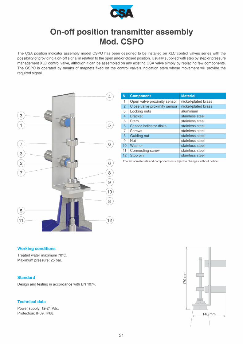
The CSA position indicator assembly model CSPO has been designed to be installed on XLC control valves series with the
possibility of providing a on-off signal in relation to the open and/or closed position. Usually supplied with step by step or pressure
management XLC control valve, although it can be assembled on any existing CSA valve simply by replacing few components.
The CSPO is operated by means of magnets fixed on the control valve’s indication stem whose movement will provide the
required signal.
On-off position transmitter assemblyMod. CSPO
Open valve proximity sensor
Close valve proximity sensor
Locking nuts
Bracket
Stem
Sensor indicator disks
Screws
Guiding nut
Nut
Washer
Connecting screw
Stop pin
nickel-plated brass
nickel-plated brass
aluminium
stainless steel
stainless steel
stainless steel
stainless steel
stainless steel
stainless steel
stainless steel
stainless steel
stainless steel
The list of materials and components is subject to changes without notice.
Design and testing in accordance with EN 1074.
Treated water maximum 70°C.
Maximum pressure: 25 bar.
Component Material
Power supply: 12-24 Vdc.
Protection: IP69, IP68.
Standard
Working conditions
Technical data

1
2
3
4
5
6
7
8
9
10
11
12
13
14
15
3
4
2
4
3
5
12
13
10
15
14
6
9
10
11
8
7
1
11
N.
265 m
m
110 mm
32
The linear position transmission system model CSPL has been designed to be installed on XLC control valves series with the
possibility of providing a 4-20 mA output in relation to the opening percentage. Usually supplied with step by step or pressure
management XLC control valve, although it can be assembled on any existing CSA valve simply by replacing few components.
The CSPL is operated by means of a magnet fixed on the control valve’s indication stem whose movement will impart the required
signal.
Contactless linear position transducer with magnetostrictive technology - Mod. CSPL
Position transducer
Bracket
Bracket connections
Screws
Magnet
Magnet support
Screws
Nuts
Screw
Stem
Guiding nut
Nut
Washer
Connecting screw
Stop pin
aluminium
stainless steel
aluminium
stainless steel
stainless steel
stainless steel
stainless steel
stainless steel
stainless steel
stainless steel
stainless steel
stainless steel
stainless steel
stainless steel
stainless steel
The list of materials and components is subject to changes without notice.
Design and testing in accordance with EN 1074.
Treated water maximum 70°C.
Maximum pressure: 25 bar.
Power supply: 24 Vdc ± 20%.
Output signal: 4-20 mA.
Protection: IP67.
Component Material
Standard
Working conditions
Technical data
1
2
3
4
5
6
7
8
N.
200
370 mm
5
6
7
3
4
S
MC
1
2
6
8
5
33
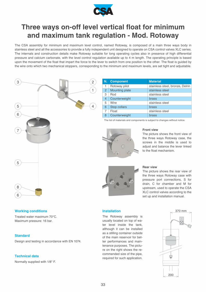
The CSA assembly for minimum and maximum level control, named Rotoway, is composed of a main three ways body in
stainless steel and all the accessories to provide a fully independent unit designed to operate on CSA control valves XLC series.
The internals and construction details make Rotoway suitable for long operating cycles also in presence of high differential
pressure and calcium carbonate, with the level control regulation available up to 4 m length. The operating principle is based
upon the movement of the float that impart the force to the lever to switch from one position to the other. The float is guided by
the wire onto which two mechanical stoppers, corresponding to the minimum and maximum levels, are set tight and adjustable.
Three ways on-off level vertical float for minimum and maximum tank regulation - Mod. Rotoway
Rotoway pilot
Mounting plate
Rod
Counterweight
Wire
Stop collars
Float
Counterweight
stainless steel, bronze, Delrin
stainless steel
stainless steel
brass
stainless steel
brass
stainless steel
brass
The list of materials and components is subject to changes without notice.
Design and testing in accordance with EN 1074.
Treated water maximum 70°C.
Maximum pressure: 16 bar.
Front viewThe picture shows the front view of
the three ways Rotoway case, the
screws in the middle is used to
adjust and balance the lever linked
to the float mechanism.
Rear viewThe picture shows the rear view of
the three ways Rotoway case with
pressure port connections, S for
drain, C for chamber and M for
upstream, used to operate the CSA
XLC control valves according to the
set up and installation manual.
Normally supplied with 1/8" F.
Component Material
The Rotoway assembly is
usually located on top of wa-
ter level inside the tank,
although it can be installed
as a stilling container outside
of the main reservoir for bet-
ter performances and main-
tenance purposes. The pictu-
re on the right shows the re-
commended size of the pipe,
required for such application.
Installation
Standard
Working conditions
Technical data

3
N.
1
2
3
4
5
6
7
8
9
10
11
12
13
14
15
16
17
18
19
20
17
14
6
8
16
10
11
7
9
19
15
18
1
12
13
5
8
4
2
20
34
Technical details
Component
Body
Cap
Position indicator
Position indicator o-ring
Upper flat o-ring
Obturator o-ring
Indicator stem
Main shaft
Guide ring
Spring
Locking nut
Upper flat
Diaphragm
Obturator
Plane gasket
Gasket holder
Seat
Seat o-ring
Pressure outlet taps
Studs, nuts and washers
Standard material
ductile cast iron GJS 500-7 or GJS 450-10
ductile cast iron GJS 500-7 or GJS 450-10
s.s. AISI 303 (nickel-plated brass from DN 300)
NBR
NBR
NBR
stainless steel AISI 303
stainless steel AISI 303
bronze CuSn5Zn5Pb5
stainless steel AISI 302
stainless steel AISI 304
painted steel Fe 37
neoprene-Nylon
AISI 303 (DN 50-65), Fe 37, GJS 500-7 (from DN 150)
NBR
stainless steel AISI 303 (304 from DN 150)
stainless steel AISI 303 (316 from DN 150)
NBR
stainless steel AISI 316
stainless steel AISI 304
Optional
stainless steel AISI 303
EPDM/Viton
EPDM/Viton
EPDM/Viton
stainless steel AISI 316
stainless s. AISI 304/316
stainless steel AISI 316
stainless s. AISI 304/316
stainless s. AISI 304/316
stainless steel AISI 316
stainless steel AISI 316
EPDM/Viton
stainless steel AISI 316
The list of materials and components is subject to changes without notice.

35
A
B
C
D
E
40,6
15
40,6 68
15 18
100 169
21 27
187
27
410 662
43 56
1126 1504
70 84
2682
111
0,6 1,0 2,3 5,2 37141,5 2,5 9,4 21
3,9 6,6 16 35 2509810 16 63 140
1,0 1,8 4,3 9,5 70272,7 4,6 17 39
8,8 15 35 80 56522022 37 141 317
13 23 54 123 87934335 60 219 494
0 2 4 6 128 101 3 5 117 9
5
15
20
10
25
1 3 4 5 6 7 8 20 40 60 80 2000200 400 600 8002 10
40/50 DN (mm)65 80 150 200 250 300 400100 125
30 1000100 300
0,01
0,02
0,03
0,04
0,05
0,06
0,07
0,08
0,2
0,3
0,4
0,5
0,6
0,7
0,8
1
0,1
2
40DN (mm)
Kv (m3/h)
50 65 80 100 125 150 200 250 300 400
Min.
Max.
DN (mm)
Min.
50 65 80 100 125 150 200 250 300 400
Max.
Max.
Technical data
Downstream (bar)
Upstream
(bar)
Head loss coefficient
Kv coefficient representing the flow rate
which is flowing through the valve fully
open, and producing a head loss of 1 bar.
Cavitation chart
The cavitation phenomenon is very impor-
tant during the proper valve sizing process
since it may lead to substantial damages,
in addition to vibration and noise. The
cavitation chart has to be used to deter-
mine whether the intersection of the line,
connecting upstream and downstream
pressure conditions, lies within one of the
5 zones to be identified as follows:
- A: Out of the possible working condi-
tions;
- B: Recommended working conditions;
- C: Incipient cavitation;
- D: Damage cavitation;
- E: Choked and unpredictable condi-
tions, please consult CSA for further
assistance.
Stroke (mm)
Pressure relief
Flow rate (l/s) Recommended
Low head loss
(0,1-0,15 bar)
Recommended flow rate
The following chart shows the recommended flow rate for the proper sizing of XLC 400 control valves.
Head loss chart
The chart indicates the head loss of XLC
400 automatic control valves fully open
versus flow rate in l/s.

3
N.
1
2
3
4
5
6
7
8
9
10
11
12
13
14
15
16
17
18
19
20
19
14
8
16
10
11
7
9
1
15
17
18
12
13
8
4
2
20
36
6
5
Technical details - Anti-cavitation version
Component
Body
Cap
Position indicator
Position indicator o-ring
Upper flat o-ring
Obturator o-ring
Indicator stem
Main shaft
Guide ring
Spring
Locking nut
Upper flat
Diaphragm
Obturator
Plane gasket
Anti-cavitation V-port
Seat for anti-cavitation system
Seat o-ring
Pressure outlet taps
Studs, nuts and washers
Standard material
ductile cast iron GJS 500-7 or GJS 450-10
ductile cast iron GJS 500-7 or GJS 450-10
s.s. AISI 303 (nickel-plated brass from DN 300)
NBR
NBR
NBR
stainless steel AISI 303
stainless steel AISI 303
bronze CuSn5Zn5Pb5
stainless steel AISI 302
stainless steel AISI 304
painted steel Fe 37
neoprene-Nylon
AISI 303 (DN 50-65), Fe 37, GJS 500-7 (from DN 150)
NBR
stainless steel AISI 303 (304 from DN 150)
stainless steel AISI 303 (316 from DN 150)
NBR
stainless steel AISI 316
stainless steel AISI 304
Optional
stainless steel AISI 303
EPDM/Viton
EPDM/Viton
EPDM/Viton
stainless steel AISI 316
stainless s. AISI 304/316
stainless steel AISI 316
stainless s. AISI 304/316
stainless s. AISI 304/316
stainless steel AISI 316
stainless steel AISI 316
EPDM/Viton
stainless steel AISI 316
The list of materials and components is subject to changes without notice.
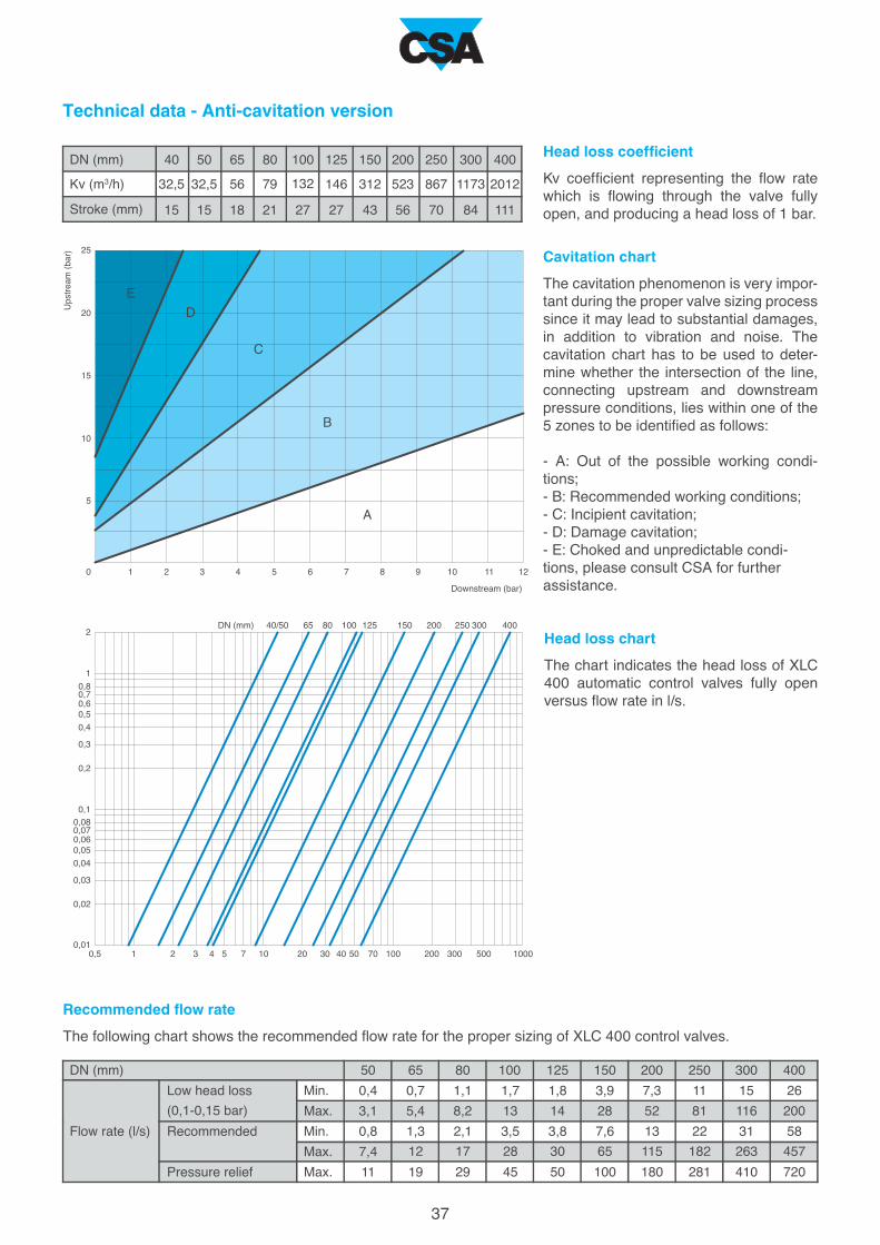
A
B
C
D
E
0 2 4 6 128 101 3 5 117 9
5
15
20
10
25
0,5 72 3 4 10 20 30 40 1000100 200 300 5001 5
40/50DN (mm) 65 80 150 200 250 300 400100 125
50 70
0,01
0,02
0,03
0,04
0,05
0,06
0,07
0,08
0,2
0,3
0,4
0,5
0,6
0,7
0,8
1
0,1
2
32,5 32,5
15
DN (mm)
Kv (m3/h) 56 79
15 18
132 146
21 27
312
27
523
43 56
867 1173
70 84
2012
111
Min.
Max.
DN (mm)
Min.
50 65 80 100 125 150 200 250 300 400
37
0,4 0,7 1,7 3,9 26111,1 1,8 7,3 15
3,1 5,4 13 28 200818,2 14 52 116
0,8 1,3 3,5 7,6 58222,1 3,8 13 31
7,4 12 28 65 45718217 30 115 263
11 19 45 100 72028129 50 180 410Max.
Max.
40 50 65 80 100 125 150 200 250 300 400
Downstream (bar)
Upstream
(bar)
Technical data - Anti-cavitation version
Head loss coefficient
Kv coefficient representing the flow rate
which is flowing through the valve fully
open, and producing a head loss of 1 bar.
Cavitation chart
The cavitation phenomenon is very impor-
tant during the proper valve sizing process
since it may lead to substantial damages,
in addition to vibration and noise. The
cavitation chart has to be used to deter-
mine whether the intersection of the line,
connecting upstream and downstream
pressure conditions, lies within one of the
5 zones to be identified as follows:
- A: Out of the possible working condi-
tions;
- B: Recommended working conditions;
- C: Incipient cavitation;
- D: Damage cavitation;
- E: Choked and unpredictable condi-
tions, please consult CSA for further
assistance.
Stroke (mm)
Head loss chart
The chart indicates the head loss of XLC
400 automatic control valves fully open
versus flow rate in l/s.
Pressure relief
Flow rate (l/s) Recommended
Low head loss
(0,1-0,15 bar)
Recommended flow rate
The following chart shows the recommended flow rate for the proper sizing of XLC 400 control valves.
100
90
80
70
60
50
40
30
20
10
0 10 20 30 40 50 60 70 80 90 100
Kv (%)
10
9
8
7
6
5
4
3
2
1
0
100
90
80
70
60
50
40
30
20
10
0
200 40 60 80 100 120 140 160 180
38
Percentage valv
e openin
g (%
)
Recom
mended w
orkin
g area
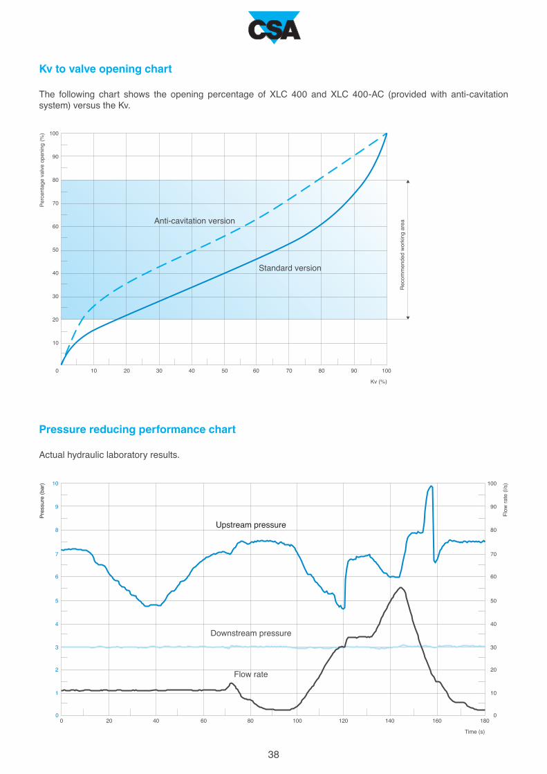
Kv to valve opening chart
The following chart shows the opening percentage of XLC 400 and XLC 400-AC (provided with anti-cavitation
system) versus the Kv.
Pressure reducing performance chart
Actual hydraulic laboratory results.
Anti-cavitation version
Upstream pressure
Downstream pressure
Flow rate
Standard version
Pressure (bar)
Flo
w rate (l/s)
Time (s)

50
40
DN
230
(mm)
A
(mm)
B
(mm)
C
(mm)
D
(mm)
E
(mm) (Kg)
162 83 233 30
65
100
150
400
250
80
125
200
300
230
290
350
480
1100
730
310
400
600
850
162
194
260
370
895
570
218
304
454
710
83
93
118
150
310
213
100
135
180
242
233
255
316
431
870
620
274
383
523
670
30
30
30
30
40
40
30
30
30
40
18
18
23,5
39
84
960
264
28
47
138
405
A
C
ØBE
D
39
The dimension E in the picture above refers only to applications where it is necessary to add a flanged orifice down-
stream or upstream of the valve, for example for flow control or cavitation prevention.
Working conditions
Treated filtered water with a maximum temperature of 70°C.
Minimum pressure on the pilot : 0,5 bar plus head loss.
Maximum pressure : 25 bar.
Available size and pattern
DN 40-DN 400 globe pattern.
Standard
Designed in compliance with EN 1074.
Pressure rating 25 bar.
Flanges according to EN 1092/2 (different drilling standard
on request).
Epoxy painting applied through FBT technology blue RAL 5005.
Technical data
The CSA XLC 400 and 400-AC series represent the state of the art of hydraulic engineering. Designed with Euro-
pean certified ductile iron and produced with potable water approved components only, XLC line of control valves
can be supplied with 4-20 mA position transmitter of the opening percentage, or on-off sensors. Turbines and power
generation systems combined with CSA electronic equipments and solutions are available on request.
Weight

40
Nuts in stainless steel
Indicator stem in stainless steel
Position indicator O-ring in NBR, EPDM or Viton
Position indicator in stainless steel or brass and Pyrex glass
Guide ring in bronze or stainless steel
Cap in ductile cast iron
Washers in stainless steel
Washer in stainless steel
Upper flat in painted or stainless steel
Locking nut in stainless steel
Spring in stainless steel
Obturator O-ring in NBR, EPDM or Viton
Diaphragm in nylon reinforced neoprene
Upper flat O-ring in NBR, EPDM or Viton
Gasket holder in stainless steel
Plane gasket in NBR
Obturator in ductile cast iron, painted or stainless steel
Seat O-ring in NBR, EPDM or Viton
Seat in stainless steel
Shaft in stainless steel
Body in ductile cast iron
Studs in stainless steel
Spare parts breakdown
Pressure outlet taps in stainless steel

41
Washer in stainless steel
Locking nut in stainless steel
Spare parts breakdown - Anti-cavitation version
Nuts in stainless steel
Indicator stem in stainless steel
Position indicator in stainless steel or brass and Pyrex glass
Guide ring in bronze or stainless steel
Cap in ductile cast iron
Washers in stainless steel
Upper flat in painted or stainless steel
Spring in stainless steel
Obturator O-ring in NBR, EPDM or Viton
Diaphragm in nylon reinforced neoprene
Upper flat O-ring in NBR, EPDM or Viton
Anti-cavitation V-port in stainless steel
Plane gasket in NBR
Obturator in ductile cast iron, painted or stainless steel
Seat O-ring in NBR, EPDM or Viton
Seat for anti-cavitation system in stainless steel
Shaft in stainless steel
Studs in stainless steel
Position indicator O-ring in NBR, EPDM or Viton
Body in ductile cast iron
Pressure outlet taps in stainless steel

42
Designed to reproduce real conditions of modern water distribution systems the CSA testing facility is able
to assess the dynamic performances of automatic control valves, direct acting pressure control valves, air
valves and anti water hammer valves.
Provided with a high capacity booster pumps station, and linked to an advanced high frequency pressure
transducers and flow meters, the testing rig allows for a real time visualization of pressure and flow
evolutions. Water hammer events can also be simulated and recorded to prove the efficacy of CSA fast
acting relief valve, in addition to level control for which, using an auxiliary stilling tank, a part of the pipeline
system is entirely dedicated.
The PLC and control station allows for the operation of step by step and solenoid operated valves to
determine the sensitivity of such kind of application and pressure management solutions. Thanks to this
important and powerful tool valves can be customized, simulated and set according to the project
requirements assuring the perfect performance and accuracy.
The testing process
All our valves undergo severe tests according to EN standards to ensure they are mechanically resistent,
watertight, and high performing. After testing every valve is identified by means of a metallic tag or sticker,
and duly registered and certified.
Advanced testing facilities

43
Water hammer analysisCSA Hyconsult
CSA Hyconsult was founded to provide
designers and consultants, involved in the
design of water distribution and sewage
systems, with accurate and unique technical
support.
CSA Hyconsult has specialized in hydraulic
modelling and transients analysis, entirely
through the use of modern computational tools
and advanced algorithms. Simulations are
essential to predict system responses to events
under a wide range of conditions without
disrupting the actual system.
Using simulations, problems can be anticipated
in possible or existing situations, and solutions
can be evaluated in order to invest time, money
and material in the most productive manner.
Research and innovation
CSA has always regarded knowledge as being
indispensable for the kind of research that
consistently feeds innovation at all levels. The
R&D department at CSA constantly strives to
improve product performance and continually
searches for new solutions to meet our
customer's needs. Twenty years of experience
in valve design and sizing, supported by
advanced computational tools, cooperation
with external entities at the highest level, and
test facilities for the verification of theoretical
results which are available for our customers,
guarantee our professionalism and reliability.

CSA s.r.l. - Strada San Giuseppe, 15 - località Ponteghiara
43039 Salsomaggiore Terme (PR) - Italy
TEL. +39.0524.523978 - FAX +39.0524.524031
www.csasrl.it - [email protected] Rev. 2
- 3/
2015