Embed Size (px)
Citation preview
Automatic Railway Gate Control
1. INTRODUCTION
Present project is designed using AT89C51 microcontroller
to avoid railway accidents happening at unattended railway gates,
if implemented in spirit. This project utilizes two powerful IR
transmitters and two receivers; one pair of transmitter and
receiver is fixed at up side (from where the train comes) at a level
higher than a human being in exact alignment and similarly the
other pair is fixed at down side of the train direction. Sensor
activation time is so adjusted by calculating the time taken at a
certain speed to cross at least one compartment of standard
minimum size of the Indian railway. We have considered 5
seconds for this project. Sensors are fixed at 1km on both sides of
the gate. We call the sensor along the train direction as ‘foreside
sensor’ and the other as ‘aft side sensor’. When foreside receiver
gets activated, the gate motor is turned on in one direction and
the gate is closed and stays closed until the train crosses the gate
and reaches aft side sensors. When aft side receiver gets activated
motor turns in opposite direction and gate opens and motor
stops. Buzzer will immediately sound at the fore side receiver
activation and gate will close after 5 seconds, so giving time to
Automatic Railway Gate Control
drivers to clear gate area in order to avoid trapping between the
gates and stop sound after the train has crossed.
The same principle is applied for track switching.
Considering a situation wherein an express train and a local train
are traveling in opposite directions on the same track; the express
train is allowed to travel on the same track and the local train has
to switch on to the other track. Two sensors are placed at the
either sides of the junction where the track switches. If there’s a
train approaching from the other side, then another sensor placed
along that direction gets activated and will send an interrupt to
the controller. The interrupt service routine switches the track.
Indicator lights have been provided to avoid collisions. Here the
switching operation is performed using a stepper motor.
Assuming that within a certain delay, the train has passed the
track is switched back to its original position, allowing the first
train to pass without any interruption. This concept of track
switching can be applied at 1km distance from the stations.
Automatic Railway Gate Control
2. WHAT IS A GATE CONTROL
Railways being the cheapest mode of transportation
are preferred over all the other means .When we go through the
daily newspapers we come across many railway accidents
occurring at unmanned railway crossings. This is mainly due to the
carelessness in manual operations or lack of workers. We, in this
project has come up with a solution for the same. Using simple
electronic components we have tried to automate the control of
railway gates. As a train approaches the railway crossing from
either side, the sensors placed at a certain distance from the gate
detects the approaching train and accordingly controls the
operation of the gate. Also an indicator light has been provided to
alert the motorists about the approaching train.
Automatic Railway Gate Control
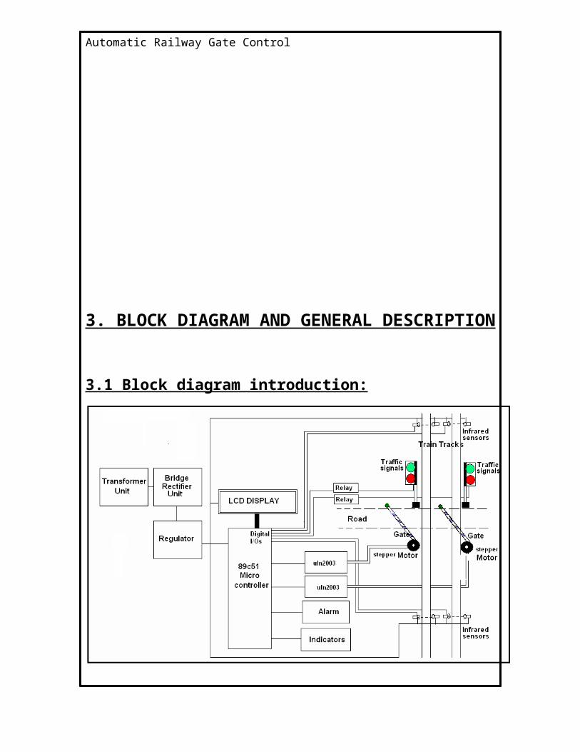
3. BLOCK DIAGRAM AND GENERAL DESCRIPTION
3.1 Block diagram introduction:
The general block diagram of unmanned railway gate control, the
various blocks of this are:
1. Power supply unit
2. Gate control unit
3. Track changing unit
4. LCD Message display unit
Automatic Railway Gate Control
This project uses AT89C51 microcontroller for programming and
operation. And ULN2003 driver.
The Block diagram consists of the power supply, which
is of single-phase 230V ac. This should be given to step down
transformer to reduce the 230V ac voltage to lower value. i.e., to
9V or 18V ac this value depends on the transformer inner winding.
The output of the transformer is given to the rectifier circuit. This
rectifier converts ac voltage to dc voltage. But the voltage may
consist of ripples or harmonics.
To avoid these ripples, the output of the rectifier is
connected to filter. The filter thus removes the harmonics. This is
the exact dc voltage of the given specification. But the controller
operates at 5V dc and the relays and driver operates at 12V dc
voltage. So the regulator is required to reduce the voltage.
Regulator 7805 produces 5V dc and regulator 7812 produces 12V
dc. Both are positive voltages.
The supply from 7805 regulator is used for the purpose of
track changing which consists of a stepper motor driven with
ULN2003 the current driver chip. The supply of 12v is given to
drive the stepper motor for the purpose of gate control. Through
uln2003
Automatic Railway Gate Control
4. OPERATION:
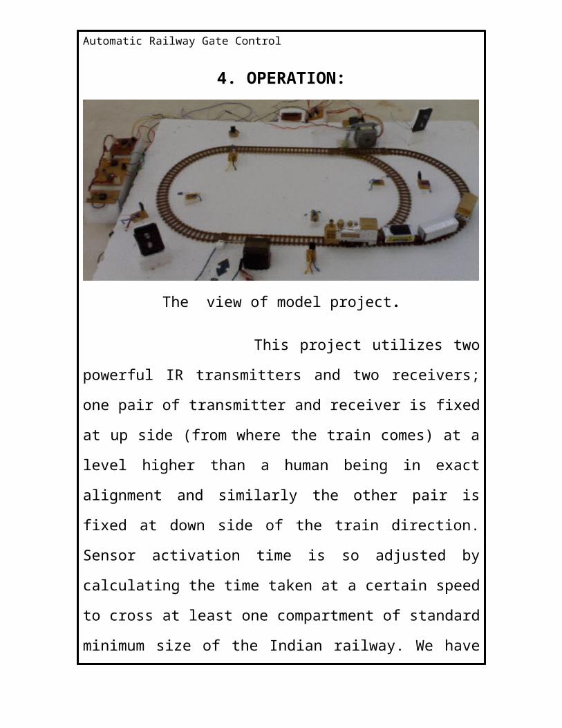
The view of model project.
This project utilizes two powerful IR transmitters and two
receivers; one pair of transmitter and receiver is fixed at up side
(from where the train comes) at a level higher than a human
being in exact alignment and similarly the other pair is fixed at
down side of the train direction. Sensor activation time is so
adjusted by calculating the time taken at a certain speed to cross
at least one compartment of standard minimum size of the Indian
railway. We have considered 5 seconds for this project. Sensors
are fixed at 1km on both sides of the gate. We call the sensor
along the train direction as ‘foreside sensor’ and the other as ‘aft
side sensor’. When foreside receiver gets activated, the gate
motor is turned on in one direction and the gate is closed and
Automatic Railway Gate Control
stays closed until the train crosses the gate and reaches aft side
sensors. When aft side receiver gets activated motor turns in
opposite direction and gate opens and motor stops. Buzzer will
immediately sound at the fore side receiver activation and gate
will close after 5 seconds, so giving time to drivers to clear gate
area in order to avoid trapping between the gates and stop sound
after the train has crossed.
The same principle is applied for track switching.
Considering a situation wherein an express train and a local train
are traveling in opposite directions on the same track; the express
train is allowed to travel on the same track and the local train has
to switch on to the other track. Two sensors are placed at the
either sides of the junction where the track switches. If there’s a
train approaching from the other side, then another sensor placed
along that direction gets activated and will send an interrupt to
the controller. The interrupt service routine switches the track.
Indicator lights have been provided to avoid collisions. Here the
switching operation is performed using a stepper motor.
Assuming that within a certain delay, the train has passed the
track is switched back to its original position, allowing the first
Automatic Railway Gate Control
train to pass without any interruption. This concept of track
switching can be applied at 1km distance from the stations.
In this project Atmel 89c51 Micro controller Integrated Chip
plays the main role. The program for this project is embedded in
this Micro controller Integrated Chip and interfaced to all the
peripherals. The timer program is inside the Micro controller IC to
maintain all the functions as per the scheduled time. The Liquid
crystal Display (LCD) is interfaced to Atmel 89c51 Micro controller
to display the message, stepper motors are used for the purpose
of gate control and track changing interfaced with current drivers
chip ULN2003 it’s a 16 pin ic.
Infrared sensors are used in this for the detection of
the train when ever it sends a signal to microcontroller the
stepper motor should operate or message will be displayed on
LCD. It consists of units called transmitter and receiver circuit.
Infrared sensor circuit consists of IC555 timer C 555
is used to construct an astable multivibrator which has two quasi-
stable states. It generates a square wave of frequency 38 kHz and
amplitude 5Volts. It is required to switch ‘ON’ the IR LED.
Automatic Railway Gate Control
A stepper motor is a widely used device that
translates electrical pulses into mechanical movement. They
function as their name suggests - they “step” a little bit at a time.
The software is written in C-language and is dumped
to the microcontroller to run the project.
Operation of this project can be explained through three units:
1. Gate control unit
2. Track changing unit
3. Announcement unit
4. Two trains opposite on same track case
Automatic Railway Gate Control
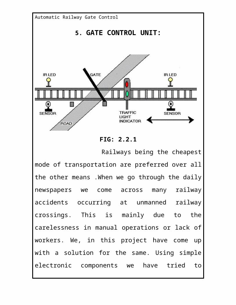
5. GATE CONTROL UNIT:
FIG: 2.2.1
Railways being the cheapest mode of transportation are
preferred over all the other means .When we go through the daily
newspapers we come across many railway accidents occurring at
unmanned railway crossings. This is mainly due to the
carelessness in manual operations or lack of workers. We, in this
project have come up with a solution for the same. Using simple
electronic components we have tried to automate the control of
railway gates. As a train approaches the railway crossing from
either side, the sensors placed at a certain distance from the gate
detects the approaching train and accordingly controls the
operation of the gate. Also an indicator light has been provided to
alert the motorists about the approaching train.
Automatic Railway Gate Control
The above figure shows the gate controlling unit block
diagram. Its operation can be explained through that.
As the figure shows it consists of two pairs of infrared
sensors placed at two sides of gate. They should keep at a
distance of 9 cm (2km in usual case) from the gate. and a stepper
motor is used for the purpose of the gate closing and opening.
Interfaced to the ULN2003.
When train reaches the sensor, it is detected by IR sensors
placed 9 cm before the station and led in the sensor will glow
because the 555 timer works into quasi state of operation. such
that the IR LED should glow till the timer works in quasi state i.e.,
when train passes away the sensors it again into normal state
then it receives 5v at terminals that pin at the 89c51 terminal
goes high which enables the power to the stepper motor to rotate
in steps which drives gate to close similarly when it reaches the
second pair of sensors it senses and send the signal to the
microcontroller to enable the current driver to open the gate by
rotating the stepper motor in steps to get back in to original
position.
Automatic Railway Gate Control
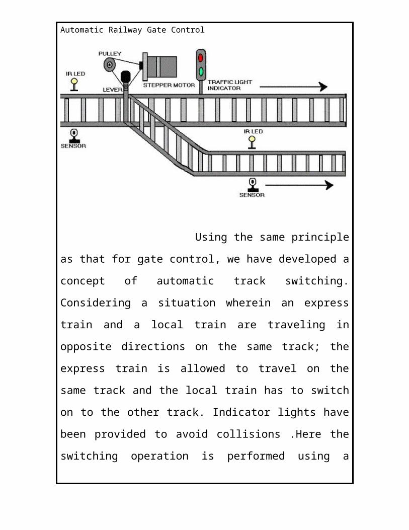
6. TRACK CHANGING UNIT
Using the same principle as that for gate control, we
have developed a concept of automatic track switching.
Considering a situation wherein an express train and a local train
are traveling in opposite directions on the same track; the express
train is allowed to travel on the same track and the local train has
to switch on to the other track. Indicator lights have been
provided to avoid collisions .Here the switching operation is
performed using a stepper motor. In practical purposes this can
be achieved using electromagnets.
Automatic Railway Gate Control
For the ease of description we are considering
only two plat forms thus this can be implemented to any number
of platforms. When train reaches the platform before a 10cm
distance apart a set of sensors are placed to detect the train and
two pair of sensors are placed on each of track at platforms.
When the train is at the first pair of sensors it sends a signal to
microcontroller to know the availability of plat form. Here after
checking availability microcontroller operates stepper motor to
change the track. The mechanism is arranged as shown in fig. but
in this case the track changing is done due to second sensor that
used to open the gate.
It consists of 5v driven stepper motor, ULN 2003
current driver chip and pulley for track changing mechanism.
6.1 Announcement unit:
Usually, announcement made at the station for the
information of train arrival and departure. In this model we are
using a buzzer for the announcement and LCD for the purpose of
display message. LCD is interfaced to 89C51 microcontroller.
Automatic Railway Gate Control
The announcement and display message is according
to the second sensor which should be used for the purpose of
gate opening.
6.2 Train arrival detection::
Detection of train approaching the gate can be sensed
by means of sensors R1, R2, R3&R4 placed on either side of the
gate. In particular direction of approach, R1 is used to sense the
arrival; R3 is used to sense the departure of the train. In the same
way R4&R2 senses arrival and departure in the other direction.
Train arrival and departure sensing can be achieved by means of
relay technique. A confined part of parallel track is supplied with
positive voltage and ground. As wheels of the train, is made up of
aluminum which is a conducting material, it shorts two parallel
tracks. When the wheels of the train moves over it, both tracks
are shorted to ground and this acts as a signal to microcontroller
(89C51) indicating train arrival. The train detection in the other
direction is done in the same way by the sensors R1 & R4. These
sensors are placed five kilometers before the gate.
6.3 warning for road users:
At that moment the train arrival is sensed on either of the
gate, road users are warned about the train approach by RED
Automatic Railway Gate Control
signal placed to caution the road users passing through the
gate .RED signal appears for the road user, once the train cuts the
relay sensor placed before the 5Kms before the gate .A buzzer is
for train, when there is any obstacle; signal is made RED for train
in order to slow done its speed before 5km from gate.
6.4 Train departure detection:
Detection of train is also done using relay techniques as
explained the head of train arrival detection. Sensor R3&R2
respectively considering direction of train approach do train
departure.
A message is displayed on LCD when train reaches
the platform. Sensed by IR sensors.
6.5 Future enhancement:
In our technique though it has many merits, but still the
power supply of 223V AC POWER is required for functioning of the
motor. It can be avoided with the help of a battery charged by a
Solar Cell. Since solar energy is an inexhaustible natural source of
energy.
6.6 Two trains opposite on same track:
We know that the rate of accidents increasing day by day, in
this because failure of mechanism at track changing two trains
coming on same track. This can also happens some times due to
Automatic Railway Gate Control
human negligence. This can avoided by using the following
unmanned detection for two trains coming on same track case.
In our model of project, we are using the gate controlling
pair of sensors to execute this method. i.e., when two trains are
coming same track at that location the two sensors will operate at
a time i.e., two 555 timers of circuit are driven in to quasi stable
state and thus corresponding two buzzer will operate at a time
and two IR LED will operate and hence signal sends to micro
processor to operate the stepper motor at tack changing.
The components that we use in order to execute are stepper
motor 5v, ULN2003, AT89C51 AND IR sensors.
6.7 Initial signal display:
Signals are placed near gate each at a specified distance.
Train may be approaching gate at either direction so all four
signals are made RED initially to indicate gate is OPENED and
vehicles are going through gate. The road user signals are made
GREEN so that they freely move through gate. Buzzer is OFF since
there is no approach of train and users need not be warned.
Automatic Railway Gate Control
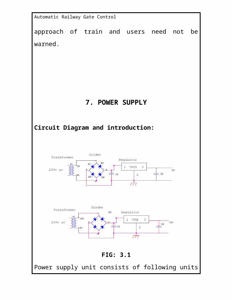
7. POWER SUPPLY
Circuit Diagram and introduction:
FIG: 3.1
Power supply unit consists of following units
7.1 Step down transformer
7.2 Rectifier unit
7.3 Input filter
7.4 Regulator unit
7.5 Output filter
Automatic Railway Gate Control
7.1 STEPDOWN TRANSFORMER
The Step down Transformer is used to step down the main
supply voltage from 230V AC to lower value. This 230 AC voltage
cannot be used directly, thus it is stepped down. The Transformer
consists of primary and secondary coils. To reduce or step down
the voltage, the transformer is designed to contain less number of
turns in its secondary core. The output from the secondary coil is
also AC waveform. Thus the conversion from AC to DC is essential.
This conversion is achieved by using the Rectifier Circuit/Unit.
7.2 RECTIFIER UNIT:
The Rectifier circuit is used to convert the AC voltage into its
corresponding DC voltage. There are Half-Wave, Full-Wave and
bridge Rectifiers available for this specific function. The most
important and simple device used in Rectifier circuit is the diode.
The simple function of the diode is to conduct when forward
biased and not to conduct in reverse bias.
The Forward Bias is achieved by connecting the diode’s
positive with positive of the battery and negative with battery’s
negative. The efficient circuit used is the Full wave Bridge rectifier
circuit. The output voltage of the rectifier is in rippled form, the
ripples from the obtained DC voltage are removed using other
Automatic Railway Gate Control
circuits available. The circuit used for removing the ripples is
called Filter circuit.
7.3 INPUT FILTER:
Capacitors are used as filter. The ripples from the DC
voltage are removed and pure DC voltage is obtained. And also
these capacitors are used to reduce the harmonics of the input
voltage. The primary action performed by capacitor is charging
and discharging. It charges in positive half cycle of the AC voltage
and it will discharge in negative half cycle. So it allows only AC
voltage and does not allow the DC voltage. This filter is fixed
before the regulator. Thus the output is free from ripples.
7.4 REGULATOR UNIT:
7805 Regulator
Regulator regulates the output voltage to be always
constant. The output voltage is maintained irrespective of the
fluctuations in the input AC voltage. As and then the AC voltage
changes, the DC voltage also changes. Thus to avoid this
Regulators are used. Also when the internal resistance of the
power supply is greater than 30 ohms, the output gets affected.
Thus this can be successfully reduced here. The regulators are
Automatic Railway Gate Control
mainly classified for low voltage and for high voltage. Further they
can also be classified as:
i) Positive regulator
1---> input pin
2---> ground pin
3---> output pin
It regulates the positive voltage.
ii) Negative regulator
1---> ground pin
2---> input pin
3---> output pin
It regulates the negative voltage.
7.5 OUTPUT FILTER:
The Filter circuit is often fixed after the Regulator circuit.
Capacitor is most often used as filter. The principle of the
capacitor is to charge and discharge. It charges during the positive
half cycle of the AC voltage and discharges during the negative
half cycle. So it allows only AC voltage and does not allow the DC
voltage. This filter is fixed after the Regulator circuit to filter any of
the possibly found ripples in the output received finally. Here we
used 0.1µF capacitor. The output at this stage is 5V and is given to
the Microcontroller.
Automatic Railway Gate Control
8. MICROCONTROLLER
8.1 Introduction:
A computer-on-a-chip is a variation of a microprocessor,
which combines the processor core (CPU), some memory, and I/O
(input/output) lines, all on one chip. The computer-on-a-chip is
called the microcomputer whose proper meaning is a computer
using a (number of) microprocessor(s) as its CPUs, while the
concept of the microcomputer is known to be a microcontroller. A
microcontroller can be viewed as a set of digital logic circuits
integrated on a single silicon chip. This chip is used for only
specific applications.
Automatic Railway Gate Control
8.2 ADVANTAGES OF USING A MICROCONTROLLER OVER
MICROPROCESSOR:
A designer will use a Microcontroller to
1. Gather input from various sensors
2. Process this input into a set of actions
3. Use the output mechanisms on the Microcontroller to do
something useful
4. RAM and ROM are inbuilt in the MC.
5. Cheap compared to MP.
6. Multi machine control is possible simultaneously.
Examples:
8051, 89C51 (ATMAL), PIC (Microchip), Motorola (Motorola),
ARM Processor, Applications:
Cell phones, Computers, Robots, Interfacing to two pc’s.
8.3 89c51 Microcontroller IC
The AT89C51 is a low-power, high-performance CMOS 8-bit
microcomputer with 4Kbytes of Flash programmable and erasable
read only memory (PEROM). The device is manufactured using
Atmel’s high-density nonvolatile memory technology and is
Automatic Railway Gate Control
compatible with the industry-standard MCS-51 instruction set and
pin out. The on-chip Flash allows the program memory to be
reprogrammed in-system or by a conventional nonvolatile
memory programmer. By combining a versatile 8-bit CPU with
Flash on a monolithic chip, the Atmel AT89C51 is a powerful
microcomputer, which provides a highly-flexible and cost-
effective solution to many embedded control applications. The
AT89C51 provides the following standard features: 4Kbytes of
Flash, 128 bytes of RAM, 32 I/O lines, two 16-bit timer/counters, a
five vector two-level interrupt architecture, a full duplex serial
port, on-chip oscillator and clock circuitry. In addition, the
AT89C51 is designed with static logic for operation down to zero
frequency and supports two software selectable power saving
modes. The Idle Mode stops the CPU while allowing the RAM,
timer/counters, serial port and interrupt system to continue
functioning. The Power-down Mode saves the RAM contents but
freezes the oscillator disabling all other chip functions until the
next hardware reset.
Automatic Railway Gate Control
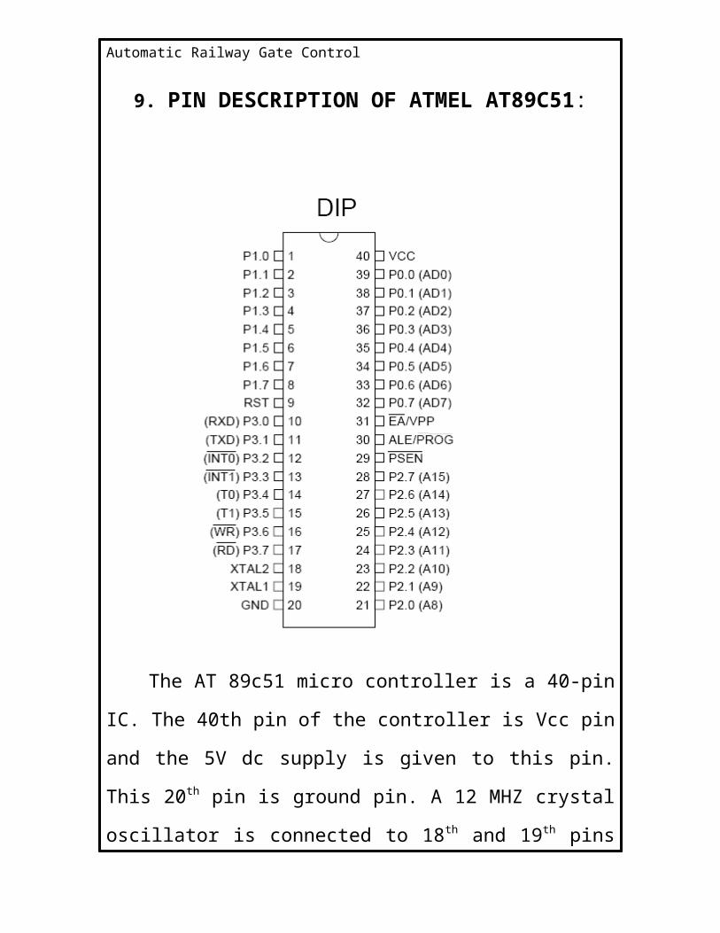
9. PIN DESCRIPTION OF ATMEL AT89C51:
The AT 89c51 micro controller is a 40-pin IC. The 40th pin of
the controller is Vcc pin and the 5V dc supply is given to this pin.
This 20th pin is ground pin. A 12 MHZ crystal oscillator is
connected to 18th and 19th pins of the AT 89c51 micro controller
Automatic Railway Gate Control
and two 22pf capacitors are connected to ground from 18th and
19th pins. The 9th pin is Reset pin.
9.1 Port 0
Port 0 is an 8-bit open-drain bi-directional I/O port. As an
output port, each pin can sink eight TTL inputs. When 1s are
written to port 0 pins, the pins can be used as high impedance
inputs. Port 0 may also be configured to be the multiplexed low
order address/data bus during accesses to external program and
data memory. In this mode P0 has internal pull-ups. Port 0 also
receives the code bytes during Flash programming, and outputs
the code bytes during program verification. External pull-ups are
required during program verification.
9.2 Port 1
Port 1 is an 8-bit bi-directional I/O port with internal pull-
ups. The Port 1 output buffers can sink/source four TTL inputs.
When 1s are written to Port 1 pins they are pulled high by the
internal pull-ups and can be used as inputs. As inputs, Port 1 pins
that are externally being pulled low will source current (IIL)
because of the internal pull-ups. Port 1 also receives the low-
order address bytes during Flash programming and verification.
Automatic Railway Gate Control
9.3 Port 2
Port 2 is an 8-bit bi-directional I/O port with internal pull-
ups. The Port 2 output buffers can sink/source four TTL inputs.
When 1s are written to Port 2 pins they are pulled high by the
internal pull-ups and can be used as inputs. As inputs Port 2 pins
that are externally being pulled low will source current (IIL)
because of the internal pull-ups. Port 2 emits the high-order
address byte during fetches from external program memory and
during accesses to external data memory that uses 16-bit
addresses (MOVX @ DPTR). In this application, it uses strong
internal pull-ups when emitting 1s. During accesses to external
data memory that uses 8-bit addresses (MOVX @ RI), Port 2 emits
the contents of the P2 Special Function Register. Port 2 also
receives the high-order address bits and some control signals
during Flash programming and verification.
9.4 Port 3
Port 3 is an 8-bit bi-directional I/O port with internal pull-
ups. The Port 3 output buffers can sink/source four TTL inputs.
When 1s are written to Port 3 pins they are pulled high by the
internal pull-ups and can be used as inputs. As inputs, Port 3 pins
that are externally being pulled low will source current (IIL)
Automatic Railway Gate Control
because of the pull-ups. Port 3 also serves the functions of various
special features of the AT89C51 as listed below:
Port Pin Alternate Functions
P3.0 RXD (serial input port)
P3.1 TXD (serial output port)
P3.2 INT0 (external interrupt 0)
P3.3 INT1 (external interrupt 1)
P3.4 T0 (timer 0 external input)
P3.5 T1 (timer 1 external input)
P3.6 WR (external data memory write strobe)
P3.7 RD (external data memory read strobe)
Port 3 also receives some control signals for Flash programming
and verification.
9.5 RST
Reset input. A high on this pin for two machine cycles while
the oscillator is running resets the device.
9.6 ALE/PROG
Address Latch Enable output pulse for latching the low byte
of the address during accesses to external memory. This pin is
also the program pulse input (PROG) during Flash programming.
Automatic Railway Gate Control
In normal operation ALE is emitted at a constant rate of 1/6 the
oscillator frequency, and may be used for external timing or
clocking purposes. Note, however, that one ALE pulse is skipped
during each access to external Data Memory. If desired, ALE
operation can be disabled by setting bit 0 of SFR location 8EH.
With the bit set, ALE is active only during a MOVX or MOVC
instruction. Otherwise, the pin is weakly pulled high. Setting the
ALE-disable bit has no effect if the micro controller is in external
execution mode.
9.7 PSEN
Program Store Enable is the read strobe to external program
memory. When the AT89C51 is executing code from external
program memory, PSEN is activated twice each machine cycle,
except that two PSEN activations are skipped during each access
to external data memory.
9.8 EA/VPP
External Access Enable. EA must be strapped to GND in
order to enable the device to fetch code from external program
memory locations starting at 0000H up to FFFFH. Note, however,
that if lock bit 1 is programmed, EA will be internally latched on
reset. EA should be strapped to VCC for internal program

Automatic Railway Gate Control
executions. This pin also receives the 12-volt programming enable
voltage (VPP) during Flash programming, for parts that require 12-
volt VPP.
9.9 XTAL1
Input to the inverting oscillator amplifier and input to the
internal clock operating circuit.
9.10 XTAL2
It is the output from the inverting oscillator amplifier.
Automatic Railway Gate Control
10. CONCLUSION
A new approach for improving safety at LCs on IR has been
suggested. Formats have been given to maintain records of LC
inventories, accident/incident reports. Each LC should be assigned
a hazard rating and the priority of safety enhancement works be
decided accordingly. A regular assessment of safety performance
should be done. This approach should be able to bring down the
rising trend in accidents at LCs.
Automatic Railway Gate Control
11. REFERENCES
1. Kenneth.J.Ayala”The 89C51 Microcontroller
Architecture programming and Applications”, Pen ram
International.
2. D.Roychoudary and Sail Jain”L.I.C”, New Age
International.
3. “Principles of Electronics” by V.K.MEHTA.
4. “Communication Systems” by Simon Hawkins.
Automatic Railway Gate Control
ABSTRACT
Aim of this project is control the unmanned
rail gate automatically using embedded platform. Today often we
see news papers very often about the railway accidents
happening at un- attended railway gates. Present project is
designed to avoid such accidents if implemented in spirit.
This project utilizes two powerful IR transmitter
and two receivers, one pair of transmitter and receiver is fixed at
upside (from the train comes) at a level higher than human being
in exact alignment and similarly other pair is fixed at down side of
the train direction sensor activation time is so adjusted by
calculating the time taken at a certain speed to cross at least one
compartment of standard minimum size of the Indian railway,
normally 5 seconds.
The sensors are fixed at 1000 meters on both
sides of the gate, we call fore side sensor pair for common
towards gate train, and aft side sensors for the train just Crosses
the gate. When train cross the fore side sensor it gives signal to
the gate receiver to close the gate. The buzzer is activated to clear
the gate area for drivers about 5 seconds. Gate motor is turned
on in one direction and gate is closed, and stay closed till train
Automatic Railway Gate Control
crosses the gate and reaches aft side sensors when aft side
receiver get activated motor turns in opposite direction and gate
opens and motor stops .
If there is any problem in the gate means it will
operate red signal on both side fro the driver indication.
Train arrival and departure sensing can be achieved
by means of Relay techniques. When the wheels of the train
moves over, both tracks are shorted to ground and this acts as a
signal to microcontroller (89C51) indicating train arrival. RED
signal appears for the road user, once the train cuts the relay
sensor placed before the 5Kms before the gate .A buzzer is made
on as a pre cautionary measure for the road users.
Automatic Railway Gate Control
CONTENTS
1. INTRODUCTION 01
2. WHAT IS A GATE CONTROL 03
3. BLOCK DIAGRAM AND GENERAL DESCRIPTION 04
4. OPERATION 06
5. GATE CONTROL UNIT 10
6. TRACK CHANGING UNIT 12
6.1 Announcement unit 13
6.2 Train arrival detection 14
6.3 warning for road users 14
6.4 Train departure detection 15
6.5 Future enhancement 15
6.6 Two trains opposite on same track 15
6.7 Initial signal display 16
7. POWER SUPPLY 17
7.1 STEPDOWN transformer 18
7.2 Rectifier Unit 18
7.3 Input Filter 19
7.4 Regulator unit 19
7.5 Output Filter 20
8. MICROCONTROLLER 21
8.1 Introduction 21
8.2 ADVANTAGES OF USING A MICROCONTROLLER OVER
MICROPROCESSOR 22
Automatic Railway Gate Control
8.3 89c51 Microcontroller IC 22
9. PIN DESCRIPTION OF ATMEL AT89C51 24
9.1 Port 0 25
9.2 Port 1 25
9.3 Port 2 26
9.4 Port 3 26
9.5 RST 27
9.6 ALE/PROG 27
9.7 PSEN 28
9.8 EA/VPP 28
9.9 XTAL1 29
9.10 XTAL2 29
10. CONCLUSION 30
11. REFERENCES 31