Embed Size (px)
Citation preview

AUTOMATIC COMPOSITION OF SEMANTIC WEB SERVICES WITH THE ABDUCTIVE EVENT CALCULUS
A THESIS SUBMITTED TO THE GRADUATE SCHOOL OF NATURAL AND APPLIED SCIENCES
OF MIDDLE EAST TECHNICAL UNIVERSITY
BY
ESRA KIRCI
IN PARTIAL FULFILLMENT OF THE REQUIREMENTS FOR
THE DEGREE OF MASTER OF SCIENCE IN
COMPUTER ENGINEERING
SEPTEMBER 2008

AUTOMATIC COMPOSITION OF SEMANTIC WEB SERVICES WITH THE ABDUCTIVE EVENT CALCULUS
submitted by ESRA KIRCI in partial fulfillment of the requirements for the degree of Master of Science in Computer Engineering Department, Middle East Technical University by, Prof. Dr. Canan Özgen ____________________ Dean, Graduate School of Natural and Applied Sciences Prof. Dr. Volkan Atalay ____________________ Head of Department, Computer Engineering Assoc.Prof.Dr. Nihan Kesim Çiçekli Supervisor, Computer Engineering Dept., METU ____________________ Examining Committee Members: Prof. Dr. Mehmet Tolun ____________________ Computer Engineering Dept., Çankaya Üniversity Assoc.Prof.Dr. Nihan Kesim Çiçekli ____________________ Computer Engineering Dept., METU Assoc.Prof.Dr. Ali Do�ru ____________________ Computer Engineering Dept., METU Assoc.Prof.Dr. Ahmet Co�ar ____________________ Computer Engineering Dept., METU Asst. Prof. Dr. Pınar �enkul ____________________ Computer Engineering Dept., METU
Date: 03.09.2008

iii
I hereby declare that all information in this document has been
obtained and presented in accordance with academic rules and ethical
conduct. I also declare that, as required by these rules and conduct, I
have fully cited and referenced all material and results that are not
original to this work.
Name, Last name : Esra Kırcı
Signature :

iv
ABSTRACT
AUTOMATIC COMPOSITION OF SEMANTIC WEB SERVICES
WITH THE ABDUCTIVE EVENT CALCULUS
Esra Kırcı
M.Sc., Department of Computer Engineering
Supervisor: Assoc. Prof. Dr. Nihan Kesim Çiçekli
September 2008, 178 pages
In today's world, composite web services are widely used in service oriented
computing, web mashups and B2B Applications etc. Most of these services
are composed manually. However, the complexity of manually composing
web services increase exponentially with the increase in the number of
available web services, the need for dynamically created/updated/discovered
services and the necessity for higher amount of data bindings and type
mappings in longer compositions. Therefore, current highly manual web
service composition techniques are far from being the answer to web service
composition problem. Automatic web service composition methods are
recent research efforts to tackle the issues with manual techniques. Broadly,
these methods fall into two groups: (i) workflow based methods and (ii)
methods using AI planning. This thesis investigates the application of AI
planning techniques to the web service composition problem and in
v
particular, it proposes the use of the abductive event calculus in this domain.
Web service compositions are defined as templates using OWL-S ("OWL for
Services"). These generic composition definitions are converted to Prolog
language as axioms for the abductive event calculus planner and solutions
found by the planner constitute the specific result plans for the generic
composition plan. In this thesis it is shown that abductive planning
capabilities of the event calculus can be used to generate the web service
composition plans that realize the generic procedure.
Keywords: Automatic Web Service Composition, OWL-S, Abductive Event
Calculus, Semantic Web Services

vi
ÖZ
ANLAMSAL ÖRÜN SERV�SLER�N�N ÇIKARIMSAL OLAY CEB�R� �LE
OTOMAT�K B�RLE��M�
Esra Kırcı
Yüksek Lisans, Bilgisayar Mühendisli�i Bölümü
Tez Yöneticisi: Doçent. Dr. Nihan Kesim Çiçekli
Eylül 2008, 178 sayfa
Günümüzde servis odaklı mimarinin, örün mashup'ları ve B2B uygulamaların
artmasıyla örün a�ı servisleri birle�imleri de geni� bir kullanım alanına sahip
olmu�tur. Bu örün a�ı servis birle�imlerinin büyük bir ço�unlu�u el ile
yapılmaktadır. Ancak bu i�lemin karma�ıklı�ı uygun örün servislerinin
sayısındaki artı�, devingen olarak olu�turulmu�/güncellenmi�/bulunmu� örün
servislerine olan gereksinim ve daha yüksek oranda veri ba�lama ve tür
e�leme ihtiyacı sebepleriyle gün geçtikçe artmaktadır. Dolayısıyla
günümüzde kullanılan el ile örün servisi birle�tirme yöntemleri bu problemin
cevabı olmaktan çok uzaktır. Bu sebeple son yıllarda otomatik örün servisi
birle�tirme metodlarının geli�tirilmesi için ara�tırmalar sürdürülmektedir. Bu
metodlar genel olarak iki ana sınıfta toplanabilir: (i) i� akı�ı temelli metodlar
ve (ii) yapay zeka ile planlama içeren metodlar. Bu tezde yapay zeka
planlama tekniklerinin örün servisi birle�imi problemine nasıl

vii
uygulanabilece�i ara�tırılmı� ve özellikle çıkarımsal olay cebirinin bu
alandaki kullanılabilirli�i irdelenmi�tir. Örün servisi birle�imleri OWL-S
("Servisler için OWL") dili ile �ablonlar halinde tanımlanmı� ve bu tanımlar
Prolog dilinde çıkarımsal olay cebiri planlayıcısının kullanabilece�i
aksiyomlara çevrilmi�tir. Bu aksiyomları kullanan planlayıcının buldu�u
çözümler, genel örün servisi birle�imi planının özel çözümlerini içeren kümeyi
olu�turmaktadır. Bu tezde olay cebirinin çıkarımsal planlama yeteneklerinin
genel örün servisi birle�imi yordamı için çözüm te�kil edecek planları
olu�turma amacıyla kullanılabilece�i gösterilmi�tir.
Anahtar Kelimeler: Otomatik Örün Servisi Birle�imi, OWL-S, Çıkarımsal Olay
Cebiri, Anlamsal Örün A�ları

viii
To My Parents

ix
ACKNOWLEDGMENTS
First and foremost I wish to express my sincerest gratitude and appreciation
to my supervisor, Assoc. Prof. Dr. Nihan Kesim Çiçekli, who has supported
me throughout my thesis with her encouragement, friendship, advice,
patience and knowledge. One could not wish for a better or friendlier
supervisor. I would have been lost without her.
Words fail to express my gratitude to my family, who raised me with their
caring, endless love and inseparable support and who taught me honesty
and the importance of working while always trying to be beneficial for my
country and for the whole world since I was a child.
I wish to thank M.Onur Özorhan, whose endless love, dedication and
persistent confidence in me has taken the load off my shoulders. His
strength, determination and support encouraged me throughout this work,
enabling me to get through the difficult times.
Finally, I wish to thank my best friend Simge Sarıgül for all the emotional
support, comradeship, entertainment, and caring she provided. I have always
felt very lucky for having the chance of getting to know her.

x
TABLE OF CONTENTS
ABSTRACT………………………………………………………………………...iv
ÖZ…………………………………………………………………………………...vi
ACKNOWLEDGEMENTS………………………………………………………...ix
TABLE OF CONTENTS…………………………………………………………...x
LIST OF FIGURES……………………………………………………………….xiii
CHAPTER
1. INTRODUCTION.................................................................................... 1 2. RELATED WORK................................................................................... 7
2.1 Web Services............................................................................... 7 2.1.1 Introduction to Web Services Model......................................... 7 2.1.2 Types of Web Services ............................................................ 9 2.1.3 Web Services Standards........................................................ 10
2.2 Web Service Discovery.............................................................. 15 2.2.1 UDDI Registries ..................................................................... 15 2.2.2 Specialized Portals and Search Engines ............................... 16 2.2.3 Peer to Peer (P2P) Methods .................................................. 17
2.3 Web Service Composition.......................................................... 17 2.3.1 Illustrative Examples .............................................................. 19 2.3.2 Techniques for Web Service Composition ............................. 20 2.3.3 Automated Web Service Composition.................................... 22
2.4 OWL-S....................................................................................... 30 2.4.1 Service Profile ........................................................................ 31 2.4.2 Process Model ....................................................................... 32 2.4.3 Service Grounding ................................................................. 34 2.4.4 Service Composition with OWL-S .......................................... 35
2.5 Event Calculus........................................................................... 39 2.5.1 The Formalism, Predicates and Axioms of the Event Calculus 39
2.6 Planning with the Event Calculus............................................... 44 2.6.1 Basic Concepts ...................................................................... 44 2.6.2 The Abductive Theorem Prover (ATP) ................................... 45
xi
3. EVENT CALCULUS AND WEB SERVICE COMPOSITION.................. 50 3.1 Architecture of the System......................................................... 50 3.2 Advantages of Using Event Calculus......................................... 51 3.3 Representation of Web Service Composition in Event Calculus 53
3.3.1 Representation of Web Services............................................ 53 3.3.2 Representation of Composition .............................................. 55 3.3.3 Representation of Control Flow.............................................. 58 3.3.4 Representation of Data Flow Between Web Services............ 61
3.4 Plan Generation with Abductive Theorem Prover (ATP)............ 62 3.4.1 Advantages of ATP ................................................................ 62 3.4.2 Plan Generation Example ...................................................... 62 3.4.3 Communication with the Real World ...................................... 63 3.4.4 Service Execution During Planning ........................................ 64
4. OWL-S TO EVENT CALCULUS TRANSLATION.................................. 67 4.1 Translation of the Goal State ..................................................... 68 4.2 Translation of Atomic Services .................................................. 69 4.3 Translation of Composite Services ............................................ 71
4.3.1 Translation of the Sequence Control Construct...................... 72 4.3.2 Translation of the Any-Order Control Construct ..................... 74 4.3.3 Translation of the Choice Control Construct........................... 76 4.3.4 Translation of the Split Control Construct............................... 77 4.3.5 Translation of the Split-Join Control Construct ....................... 78 4.3.6 Translation of the If-Then-Else Control Construct .................. 79
4.4 Translation of the Preconditions ................................................ 81 5. IMPLEMENTATION.............................................................................. 84
5.1 Web Interface ............................................................................ 84 5.2 OWL-S Parsing.......................................................................... 86
5.2.1 OWL-S API............................................................................. 87 5.2.2 CMU OWL-S API ................................................................... 87
5.3 Graphical Representation .......................................................... 88 5.4 Generation of Prolog code......................................................... 90
5.4.1 Incremental Prolog Code Generator ...................................... 90 5.4.2 Process Model Based Prolog Generator................................ 91
5.5 Input and Output Bindings ......................................................... 93 5.6 Simple Compositions ................................................................. 96 5.7 Recursive Compositions ............................................................ 98 5.8 Handling Preconditions............................................................ 100 5.9 Invocation and Plan Generation............................................... 101
5.9.1 JPL Library ........................................................................... 101 5.9.2 Calls from Prolog to Java ..................................................... 102 5.9.3 Calls from Java to Prolog ..................................................... 106 5.9.4 Input Types .......................................................................... 108

xii
5.9.5 Service Discovery at Execution Time................................... 109 5.9.6 Plan Selection ...................................................................... 110 5.9.7 Execution Mode ................................................................... 112
5.10 System Performance ............................................................... 114 5.10.1 Network Delays .................................................................... 114 5.10.2 RDF Parsing......................................................................... 117 5.10.3 JPL Calls and Prolog............................................................ 118
6. CONCLUSION AND FUTURE WORK................................................ 119 6.1 Summary and Conclusions...................................................... 119 6.2 Future Work............................................................................. 122
REFERENCES .......................................................................................... 124
APPENDICES ........................................................................................... 134
A. SEQUENCE EXAMPLE..................................................................... 134 B. EXAMPLE IN TRAVEL DOMAIN........................................................ 143 C. PERFORMANCE CHARTS ............................................................... 164
xiii
LIST OF FIGURES
Figure �1.1 Web Service Framework .............................................................. 8 Figure �1.2 SOAP message containing a header block and a body.............. 13 Figure �1.3 The Framework of the Service Composition System.................. 23 Figure �1.4 Planning Graph........................................................................... 29 Figure �1.5 OWL-S Model ............................................................................. 31 Figure �1.6 How the Event Calculus Functions ............................................. 41 Figure �1.7 Event Calculus Predicates.......................................................... 41 Figure �1.8 (a) Total order plan (b) Partial order plan ................................... 44 Figure �1.9 Abductive Theorem Proving ....................................................... 47 Figure �3.1 The System Architecture ............................................................ 51 Figure �3.2 Representation of a Single Web Service .................................... 53 Figure �3.3 Graphical Representation of a Simple Composite Process ........ 55 Figure �3.4 Representation of A Simple Composition ................................... 56 Figure �3.5 Graphical Representation of a Recursive Composite Process ... 57 Figure �3.6 Simple Composition with Any-Order Control Construct .............. 65 Figure �4.1 OWL-S Representation of an Atomic Service............................. 70 Figure �4.2 Event Calculus Representation of an Atomic Service................. 71 Figure �4.3 A Composition with the Sequence Construct in OWL-S ............. 73 Figure �4.4 Translation of Sequence to Event Calculus................................ 74 Figure �4.5 A Composition with the Any-Order Construct in OWL-S............. 75 Figure �4.6 Translation of Any-Order to Event Calculus ............................... 76 Figure �4.7 Translation of Choice to Event Calculus..................................... 77 Figure �4.8 Translation of Split to Event Calculus ......................................... 77 Figure �4.9 Translation of Split-Join to Event Calculus ................................. 78 Figure �4.10 A Composition with the If-Then-Else Construct in OWL-S........ 80 Figure �4.11 Translation of If-Then-Else to Event Calculus........................... 80 Figure �4.12 A Precondition Example in OWL-S........................................... 82 Figure �4.13 Translation of Precondition to Event Calculus .......................... 82 Figure �4.14 Body of the Precondition Event ................................................ 83 Figure �5.1 OWL-S File/URL Upload Step .................................................... 85 Figure �5.2 OWL-S Composition: Graphical Representation Step................ 90 Figure �5.3 Prolog Code Display................................................................... 93 Figure �5.4 A Sample Output Binding in OWL-S........................................... 94

xiv
Figure �5.5 A Simple Composition in OWL-S................................................ 96 Figure �5.6 A Simple Composition Axiom in Prolog ...................................... 97 Figure �5.7 A Recursive Composition ........................................................... 99 Figure �5.8 Prolog for An Atomic Process with a Simple Precondition........ 102 Figure �5.9 JPL Method Definitions in Event Calculus ................................ 104 Figure �5.10 JPL Call of an If Condition in an If-Then-Else Process ........... 106 Figure �5.11 JPL Call to a Composition from Java...................................... 107 Figure �5.12 OWL-S Composition Input Screen.......................................... 109 Figure �5.13 Plan Selection Step ................................................................ 111 Figure �5.14 Plan Execution Step ............................................................... 113 Figure �5.15 Execution Output Step............................................................ 114 Figure �5.16 Local vs. Remote Resource Usage ........................................ 116 Figure �5.17 Distribution of Delays in a Choice Type of Composition ......... 117 Figure �5.18 JPL Delays for a Sample Any-Order Composition.................. 118 Figure �C.1 Performance Charts................................................................. 165

1
CHAPTER 1
INTRODUCTION
In the early days of computing, organizations were monolithic and focused
on static and centralized applications. Changes were perceived as problems
disrupting the normal flow, schedule, budget etc, and they should be
avoided. But nowadays the world is much more dynamic and fast
organizational responses to rapidly changing intra and extra organizational
requirements are needed. The need for changing the systems quickly
according to the context gives rise to the usage of off-the-shelf components.
Web service technology gains importance in this context as one of the most
prominent paradigms for building complex web based applications.
According to the IBM web service tutorial [�67] the definition of web services
is as follows: “Web services are a new breed of web application. They are
self-contained, self-describing, modular applications that can be published,
located, and invoked across the web. Web services perform functions, which
can be anything from simple requests to complicated business processes. …
Once a Web service is deployed, other applications (and other web services)
can discover and invoke the deployed service.” Web services architecture is
loosely coupled and service oriented. The Web Service Description

2
Language (WSDL) [�13] is used to describe the interface of the service. It
uses the XML format to describe the methods provided by a web service,
including input and output parameters, data types and the transport protocol,
which is typically HTTP, to be used. The Universal Description Discovery and
Integration standard (UDDI) [�74] is used to publish details about a service
provider, the services that are stored and the opportunity for service
consumers to find service providers and web service details. The Simple
Object Access Protocol (SOAP) [�24] is used for XML formatted information
exchange among the entities involved in the web service model.
One drawback of WSDL is that, it does not supply the specification of what
happens when a web service is used in a machine interpretable way. To
make use of a web service, a software agent needs a computer-interpretable
description of the service, and the means by which it is accessed. Semantic
web provides some answers to this problem. The semantic web is a set of
technologies for representing, and publishing computer-interpretable
structured information on the web. Standard languages including the
resource description framework (RDF), RDF schemas (RDFS), and the web
ontology language (OWL) have been developed for enabling the creation of
ontologies for any domain and the instantiation of these ontologies in the
description of specific web components. In an environment of semantically
annotated services, users who need to achieve certain goals could be
assisted by software agents which automatically identify and, if necessary,
dynamically compose services in order to accomplish the user's goals, which
may be either explicitly stated or derived from the situation the user is in. In
order to use semantic web techniques to automate dealings with web
services, OWL-S have been developed. OWL-S [�34] is an ontology of service
concepts that supplies a web service designer with a core set of markup
3
language constructs for describing the properties and capabilities of a web
service in an unambiguous, computer-interpretable form. OWL-S allows for
the description of a web service in terms of a Profile, which tells "what the
service does", a Process Model, which tells "how the service works", and a
Grounding, which tells "how to access the service". These semantically rich
descriptions enable automated machine reasoning over service and domain
descriptions, thus supporting automation of service discovery, composition,
and execution, and reducing manual configuration and programming efforts.
Moving onto the web service composition problem, sometimes no single web
service can satisfy the user’s requirement. In this case, there arises a need
to combine existing services so that the combination would fulfill the user’s
requirement. The service oriented architecture is based on this idea. It is
possible to create applications by combining the convenient web services
together. Recursive compositions can be created by using a composite
service as an individual service contained in the composition. To define such
an application, a flow specification is needed to describe in which order
messages have to be exchanged between the services. There are many flow
specification languages for web services like BPEL4WS [�15] and WSCI [�3].
The composition should be defined manually using these languages, but
there are some problems about it. First, the amount of available web services
is too much, and they can be created and updated on the fly. Thus the
composition system needs to detect the updating at runtime and the decision
should be made based on the up-to-date information. In addition, the web
services are usually developed by different organizations that use different
models for presenting the properties of the services. This requires the
processing of semantic information about the services, for finding the

4
suitable service and composing it. Handling these issues manually in a short
time with human intervention is beyond the human capability. Thus the ability
to efficiently select and compose web services seamlessly and dynamically
in runtime becomes an important issue, which is the so called problem of
automated web services composition. Given a repository of service
descriptions and a service request, the web service composition problem
involves finding multiple web services that can be put together in correct
order of execution to obtain the desired service [�14]. Finding a web service
that can fulfill the request alone is referred to as web service discovery
problem [�42]. When it is impossible for one web service to fully satisfy the
request, one has to compose multiple web services, in sequential or parallel,
preferably in an automated fashion [�14].
The web service composition problem is similar to the AI planning problem in
many ways, which for over three decades, has investigated the problem of
how to synthesize complex behaviors given an initial state, an explicit goal
representation, and a set of possible state transitions. It is often assumed
that a business process or application is associated with some explicit
business goal definition that can guide a planning-based composition tool to
select the right service [�37]. Both the planning problem and composition
problem seek a (possibly partially) ordered set of operations that would lead
to the goal starting from an initial state (or situation). Also, like actions in
planning domain, compositions have web services which have parameters,
preconditions, results and effects. Hence AI planning is a very suitable and
attractive method for the web service composition problem.
There is a considerable amount of work on automated web service
composition with AI planning techniques. Viewing the composition problem

5
as an AI planning problem, different planners are employed for the solution
[�32, �36, �37,�42, �44, �46]. The techniques introduced so far are using the
situation calculus, the Planning Domain Definition Language (PDDL), rule-
based planning, the theorem proving and others. For instance, the STRIPS
[�19] is the first major AI planning system to describe actions in terms of their
preconditions and effects. The Graphplan [�10] is a general-purpose planner
for STRIPS-style domains using graph algorithms. Given a problem
statement, Graphplan uses a backward search to extract a plan and allows
for partial ordering among actions. As the satisfiability approach for the
planning problems, the SATPlan algorithm [�29] is a greedy local search
method that translates a planning problem into propositional axioms and
finds a model that corresponds to a valid plan [�42].
In this thesis, it is shown that the abductive planning capabilities of the event
calculus [�50] has the necessary features to be used for the solution of web
service composition problem. Our tool constitutes a proof of concept showing
this. It is shown that the composition problem can be represented and solved
completely in a logical framework, taking the advantage of its declarative
behaviour and clear semantics, which enables the easy development and
solution of the problem. When the composition is represented as event
calculus axioms, it is possible to apply planning methods of the event
calculus given the initial state and goal state. Abduction is used in planning,
and the necessary steps for reaching the goal state are found by the planner.
The generic web service composition template is to be provided by the user,
and our tool generates a set of possible execution plans which would satisfy
the goal on execution. The generic composition definitions are represented in
OWL-S, which enables the definition of semantic information of the
composite service and the individual services included in the composite

6
service. The inputs, outputs, preconditions and effects of the services are
provided by the OWL-S and the composition is translated to event calculus
framework. In the planning process, web service discovery is needed to
guide the plans and also, after the user selects one of the generated plans
for execution, the composite service is to be executed. Both of the discovery
and execution parts are out of the scope of this thesis, so the role of these
parts are simulated.
The rest of the thesis is organized as follows. Chapter 2 gives insight
information about web services, OWL-S and the event calculus. Also current
technologies and techniques for the solution of web service discovery and
composition problems are presented. Chapter 3 presents the abductive
implementation of the event calculus and the usage of it in web service
composition problem to generate the composition plans automatically. In
Chapter 4, methods to translate service descriptions in OWL-S to event
calculus axioms are presented. The implementation of our solution is
described in Chapter 5. Finally, conclusions and possible future work are
presented in Chapter 6.
7
CHAPTER 2
RELATED WORK
In this chapter, some background information on Web services, Web service
discovery/composition methods, OWL-S and Event Calculus is provided. The
purpose of this chapter is to describe the basic concepts, introduce the
necessary terminology, and present relevant definitions.
2.1 Web Services
2.1.1 Introduction to Web Services Model
According to W3C (World Wide Web Consortium) definition in the Web
Services Architecture document [�11], Web services are software systems
designed to support interoperable machine-to-machine interaction over a
network. They are considered as self-contained, self-describing, modular
applications that can be published, located, and invoked across the Web
[�58]. As the current Web enables users to connect to applications, the web
services enable applications to connect to other applications in a way that it
provides an interface for applications to publish their functions or messages
to the rest of the world so that other applications can use them across the

8
Web. Web services are therefore a key technology in enabling business
models to move from B2C (Business to Consumer) to B2B (Business to
Business) [�21].
There are three roles in the Web service model to accomplish the above
task, namely the service provider, the service requestor and the service
registry. The service provider publishes the service description to the service
registry. This description includes the format for requests and responses for
the service. The service requester then finds the service description via the
service registry. The description of the service in the registry contains
sufficient information for the service requestor to bind to the service provider
to use the service. So after the requestor finds the service it needs, the
service registry fullfills its task and the remaining interaction is carried over
between the service requestor and the service provider themselves. vFigure
2.1 shows a graphical representation of this traditional web service model.
Figure �1.1 Web Service Framework

9
2.1.2 Types of Web Services
Web services can be categorized in three groups according to their uses:
1. Web services as reusable application components: There are
common patterns that are used by different applications. Web
services can be used for those common parts so that each application
would not need to contain the common job, instead they can use the
Web service fulfilling that functionality. The ideal case is that, there will
only be one type of each application component, and anyone can use
it in their application.
2. Web services for connecting existing software: Web services help
solve the interoperability problem by giving different applications a
way to link their data. Using Web services one can exchange data
between different applications and different platforms.
3. Web services as parts of a bigger Web service: Usually Web
services should be connected to each other as a workflow to meet the
user’s needs. This is known as the Web service composition problem
and will be investigated in Section 2.3.
Web services can also be categorized according to the task performed inside
them. There are two categories falling into this group:
1. Information-Providing Web services: These services can be
defined as services that return information only about the initial state,
and do not have any world-altering effects. Most services of this kind
are stateless, i.e they only provide information about the current state
of the world, but do not change that state. Services such as flight
information providers, map services, temperature sensors, and
cameras can be given as examples of this kind.

10
2. World-Altering Web services: If a Web service has an effect on its
domain after the execution, it is accepted to be a World-Altering Web
Service [�5]. Services such as flight-booking programs, sensor
controllers, and a variety of e-commerce and business-to-business
services can be given as examples of this kind.
2.1.3 Web Services Standards
Web services may be defined and running on diverse environments. They
can be mapped to any implementation language, platform, object model, or
messaging system. In order to provide interoperability among applications
and Web services, some standards are defined. Firstly, Web services have
an interface described in a machine-processable format (specifically WSDL).
Other systems interact with the Web service in a manner defined by its
description using SOAP messages, typically conveyed using HTTP with an
XML serialization in conjunction with other Web-related standards [�25].
These standards have lowered costs and shortened development timelines.
The following sections provide more detailed descriptions of these standards.
2.1.3.1 WSDL (Web Services Description Language)
The web services description language (WSDL) [�13] has been developed for
the necessity of a standard way of defining services. It is an XML-based
language for describing Web services and methods of interacting with them
along with the message format and protocol details. A WSDL document
defines “services” as collections of network endpoints, or “ports” [�13], and
defines “binding” as a common mechanism used to attach a specific protocol
or data format or structure to an abstract message, operation, or endpoint,
which allows the reuse of abstract definitions. This “binding” mechanism is in
practice likely to be another XML-based standard, SOAP [�24].

11
There are two different kinds of users for WSDL documents:
• The developer: During development of an application that will use a
web service, the developer needs to know the interface to the service
that the application will bind to.
• The application: When the application is running it needs details of a
specific implementation of that service so that it can bind to it.
WSDL describes four critical pieces of data in the definition of Web services
[�28]:
• Datatype information for all message requests and message
responses.
• Interface information describing all publicly available functions.
• Binding information about the transport protocol to be used.
• Address information for locating the specified service.
It uses the following elements for these definitions [�13]:
• Types: A container for data type definitions using some type system
(such as XSD).
• Message: An abstract, typed definition of the data being
communicated.
• Operation: An abstract description of an action supported by the
service.
• Port Type: An abstract set of operations supported by one or more
endpoints.
• Binding: A concrete protocol and data format specification for a
particular port type.
• Port: A single endpoint defined as a combination of a binding and a
network address.

12
• Service: A collection of related endpoints.
2.1.3.2 SOAP
SOAP [�24] is a standard communication protocol for XML-based information
exchange between distributed applications. The acronym “SOAP” once stood
for “Simple Object Access Protocol” but SOAP Version 1.2 [�24] doesn't
define "SOAP" as an acronym anymore since it is considered to be
misleading. SOAP specifies the format of the request and response XML
documents and provides a platform for a distributed processing model where
communication is between applications or Web services via Internet. This
distributed processing model can support many message exchange patterns
such as one-way messages, request/response interactions and peer-to-peer
conversations.
SOAP is based on XML and consists of three parts: a SOAP envelope
(describing what's in the message and how to process it); a set of encoding
rules, and a convention for representing RPCs (Remote Procedure Calls)
and responses. SOAP messages can be carried by a variety of network
protocols; such as HTTP, SMTP, FTP, RMI/IIOP, or a proprietary messaging
protocol, but mainly HTTP is used for message exchange. There is a
standard way of encoding WSDL messages in SOAP to achieve
interoperability. By definition, SOAP is a stateless, one-way message
exchange paradigm; but applications can create more complex interaction
patterns by combining such one-way exchanges.
According to the SOAP Version 1.2 specification, SOAP messaging
framework consists of the following items:

13
• The SOAP processing model defining the rules for processing a
SOAP
• The SOAP Extensibility model defining the concepts of SOAP features
and SOAP modules
• The SOAP underlying protocol binding framework describing the rules
for defining a binding to an underlying protocol that can be used for
exchanging SOAP messages between SOAP nodes.
• The SOAP message construct defining the structure of a SOAP
message.
The details of these items can be found in [�24].
SOAP has an extensibility mechanism which can be used to add capabilities
found in richer messaging environments. Some example features with which
SOAP may be extended may be "reliability", "security", "correlation" and
“routing". Also SOAP may be extended with some message exchange
patterns such as request/response, one-way, and peer-to-peer
conversations.
The following example from [�24] shows a sample notification message
expressed in SOAP. <env:Envelope xmlns:env="http://www.w3.org/2003/05/soap-envelope"> <env:Header> <n:alertcontrol xmlns:n="http://example.org/alertcontrol"> <n:priority>1</n:priority> <n:expires>2001-06-22T14:00:00-05:00</n:expires> </n:alertcontrol> </env:Header> <env:Body> <m:alert xmlns:m="http://example.org/alert"> <m:msg>Pick up Mary at school at 2pm</m:msg> </m:alert> </env:Body> </env:Envelope>
Figure �1.2 SOAP message containing a header block and a body

14
2.1.3.3 UDDI (Universal Description, Discovery and Integration)
UDDI [�74] is a platform independent registry system that provides a
standardized way for publishing and discovering services over the Internet. It
is an open industry initiative, sponsored by OASIS [�72]. UDDI is itself a web
service which uses World Wide Web Consortium (W3C) and Internet
Engineering Task Force (IETF) internet standards such as XML, HTTP, and
DNS protocols; and can be accessed via SOAP from an application that
wishes to discover web services. UDDI specifies interfaces for applications to
publish and discover web services. WSDL can be considered as the main
interface but a UDDI entry actually contains more than just a WSDL interface
and implementation, it can also include further metadata such as quality of
service parameters, payment mechanisms, security and keywords for
resource discovery. UDDI discovery mechanisms can be classified as both
keyword and table-based.
There are three main parts of UDDI:
• White Pages: Contact information about the businesses that
developed the Web services is listed.
• Yellow Pages: Web services are organized according to their
categories.
• Green Pages: Technical details of offered services (WSDL
descriptions) are given.
With these standards we have the infrastructure to publish (WSDL, UDDI),
find (WSDL, UDDI) and bind (WSDL, SOAP) web services in an
interoperable manner.
15
2.2 Web Service Discovery
Web service discovery is "the act of locating a machine processable
description of a Web service that may have been previously unknown and
that meets certain functional criteria" [�11]. Generally speaking, the need for
web service discovery could emerge in two phases: development phase and
execution phase [�22].
In the development phase the designer of the composition or an intelligent
software agent discovers the services that will be necessary to build a
composition. In the execution phase, instances of services matching a
specific interface will be discovered, to replace or assist services already in a
composition.
The challanges in service discovery are the heterogenity of the descriptions,
ontological and vocabulary related disagreements and the scattered
distribution of service providers.
There are several approaches to web service discovery, these are:
centralized Universal Description, Discovery and Integration (UDDI)
registries, specialized portals, search engines and peer to peer methods [�6].
2.2.1 UDDI Registries
UDDI is an open industry initiative supervised by OASIS [�72] and has been
proposed as a core web service standard in 2000. UDDI specification
includes APIs to allow querying and publishing information to the registry, the
data model for services to be stored on the registry. Being a centralized and
16
XML based corporate information repository, UDDI registries were planned
to be the key indexes for publicly available web services.
Since 2006, most of the publicly available UDDI registries have been
discontinued and UDDI has been mostly used as an internal repository within
the company networks [�6]. The main reasons for the less than expected
popularity of UDDI are: (i) the need for keywords, service name and manual
selection of discovered services, (ii) lack of coverage of the web services
available publicly (iii) the simplicity of the available search tools (iv) lack of
correlations between web services and quality of service information.
There are several approaches trying to incorporate the semanticity of OWL-S
with the keyword based capabilities and centralized indexing of UDDI by
adding OWL-S descriptions to UDDI registries [�56].
2.2.2 Specialized Portals and Search Engines
There are specialized portals and search engines for web services discovery
like XMethods, BindingPoint, Web Service List and StrikeIron [�6]. Most of
these web sites allow the manual registration of services, and some of them
also have intelligent crawlers for web service indexing themselves. Search
engines such as Google also index web service descriptor documents. Using
text search methods an agent can search through WSDL and OWL-S
documents to find services required.
Even though the traditional search engines have a much larger database of
service descriptions in contrast to specialized portals, there are no
specialized query methods for the service description documents. To
improve the performance of search engines in web service discovery, web

17
service providers can use standardized vocabularies such as eClass [�66]
and search engine providers can implement different searching and
processing routines for WSDL/OWL-S files.
2.2.3 Peer to Peer (P2P) Methods
P2P overlay networks provide infrastructures for routing information between
the nodes of a decentralized environment. In a P2P web service discovery
environment, the nodes of the network may also be the publishers of the
services they index. Proposed P2P systems for web service discovery
include CAN [�47], Pastry [�49] and Chord [�57].
In the P2P overlay systems nodes are assigned id numbers from a global
address space. Each peer in the network stores information about the
network to appropriately route queries. Peers consult their lookup tables
when a query is received and route the query to an appropriate peer that
stores the queried key [�22].
The advantage of P2P service discovery is that the users can access more
up-to-date web services, since the hosts in the P2P network can publish and
update their web services dynamically.
2.3 Web Service Composition
Recently, many companies and organizations prefer to implement just their
core business, and outsource other applications they use by making use of
web services over the Internet. So it has become an important issue
finding/selecting the right web services to fulfill the given goal and integrating

18
them easily and efficiently. But this task has become more difficult because
of the poliferation of web services. It becomes even more difficult when there
is no web service capable of satisfying the functionality required by the user,
but there should be a combination of existing web services in order to fulfill
the request. The problem of combining multiple web services to satisfy a
single task is called web services composition problem, and a considerable
amount of research has been done on it in academia and in industry [�46].
Manual, semi-automated and automated solutions are proposed to the
problem. In manual solutions, the user generates the workflow, finds the
services and sends them to the execution engine. However due to the
increase on the number of services it becomes more and more diffucult for
users to deal with locating the exact services and integrating them. Semi-
automated techniques facilitates user tasks by making suggestions for
service selection, however the user is still responsible for constructing the
workflow and making service selection from a short list [�28]. Automatic
techniques aim to select, combine, integrate and execute web services to
achieve a user’s objective automatically.
Service composition in general can be differentiated into synthesis and
orchestration [�31]. Synthesis refers to generating a plan how to achieve a
desired behavior by combining the abilities of multiple services. In contrast,
orchestration refers to coordinating the control and data flow among the
various components when executing that plan [�31]. Orchestration is an
important problem that is complementary to synthesis. Examples of "service
composition" approaches referring to orchestration include [�45, �8]. In this
thesis, focus is on automatic synthesis.

19
2.3.1 Illustrative Examples
The following is a motivating example for web service composition problem
from [�42]: Suppose there are two web services available: (1) findRestaurant:
returns a name, phone number, and address of the closest restaurant
provided a zip code and food preference; and (2) findDirection returns driving
direction and a map image provided a start and destination addresses.
“Sylvie” visits “State College, PA” on a business trip and stays in the
“Atherton” hotel at “100 Atherton Ave, 16801, PA.” Now, she wants to find a
Thai restaurant near the hotel along with a driving direction. We can see that
neither of two web services can satisfy the request alone. findRestaurant can
find a Thai restaurant near the hotel, but cannot provide a driving direction.
On the other hand, the web service findDirection can give a direction from
one location to another, but cannot locate a restaurant. Therefore, one has to
combine both web services to jointly satisfy the request as follows: (1) invoke
findRestaurant(“16801”, “Thai”) to get the address of the closest restaurant,
say “410 S. Allen St. 16802, PA”; and (2) invoke the web service
findDirection(“100 Atherton Ave, 16801, PA”, “410 S. Allen St. 16802, PA”) to
get the driving direction.
Some other examples posed to be solved with the help of automatic web
service composition techniques are [�5]:
• Traveling Domain: It is the domain of trip planning systems that offer
to query and book transportation and accommodation according to
user-defined constraints [�27]. A typical problem of this domain is to
plan a trip for a conference attendance with constraints like the date
and place of the conference, preferences for certain hotels or airlines
[�37].
20
• Appointment Scheduling Domain: It is the domain of schedule
organizing systems that offer multiple appointments according to user
constraints. A typical instance is arranging a schedule after a visit to a
doctor that involves tasks of prescription filling in pharmacy, diagnostic
tests in different medical test centers and a final follow-up meeting
with the doctor [�9].
• Commercial Sale Domain: It is the domain of electronic sale system
that offers purchasing of items according to customer constraints or
quality of service (QoS) [�60] parameters. For instance a customer
wants to buy a microprocessor but s/he does not want to know where
or how to buy the item [�36].
2.3.2 Techniques for Web Service Composition
As the need for the web services composition is grown, several techniques
have been risen up for this area. There are several composition languages
that have been proposed for defining the web services composition, such as
BPML [�2], IBM's WSFL [�26, �33], Microsoft's draft of XLANG [�59], and
Business Process Execution Language for Web Services (BPEL4WS) [�1].
Almost all of these flow languages use/extend WSDL as the web service
definition language.
XLANG models the entities as services and specifes interaction among their
operations using contract construct. The details of how a service performs its
work are given in the behaviour section using any of sequential, concurrent,
conditional, loop and non-deterministic constructs. The main differences
between XLANG and WSFL are that XLANG does not provide for separate
control and data link specification, and it has support for delay and rollback-
recovery (called compensation) of operations.

21
BPEL descriptions are XML documents, which describe the roles involved in
the message exchange, supported port types and orchestration, and
correlation information as aspects of a process. BPEL4WS is a service
composition model, which supports both, composition and coordination
protocols. It also consists of an activity-based component model, an
orchestration model that allows the definition of structured activities, XML
schema data types, a service selection model and a mechanism for
exception, event and compensation handling. BPEL4WS has become a
standard for defining the business process for the Web services composition
later.
Despite all these efforts, web service composition is still a very complex and
challenging task, and dealing with it manually is beyond the human
capability. The problems with it can be listed as follows [�46]: First, the
number of services available over the web increases dramatically during the
recent years, and one can expect to have a huge web service repository to
be searched. Second, web services can be created and updated on the fly,
thus the composition system needs to detect the updating at runtime and the
decision should be made based on the up to date information. Third, web
services can be developed by different organizations, which use different
models to describe the services, but, there does not exist a universal
language to define and evaluate the web services in an identical means.
Therefore, building composite web services with an automated or
semiautomated tool is a very critical issue.
Before performing a web service composition, some basics to enable service
composition have to be performed. Six different issues that have a large
impact on service composition have been identified: Coordination,

22
transaction, context, conversation modelling, execution monitoring,
infrastructure. Details can be found in [�17].
Web service composition methods can be grouped according to the following
categories of composition strategies:
• Static or dynamic composition strategies
• Model driven service composition
• Business rule driven service composition
• Declarative service composition
• Automated or manual service composition
• Small or large scale composition
• Compositions using simple or complex operator
• Template-based, interface-based, and logic-based systems
We will investigate the automated service composition methods in the
following section. Details about the other categories can be found in [�42], [�17]
and [�20].
2.3.3 Automated Web Service Composition
Automated web service composition allows service consumers to generate
and change the composition structure on the fly and adapt it to changing
conditions. Despite its difficulties, dynamic service composition provides
several benefits to the emerging applications, namely, flexibility, adaptability,
and availability. It accelerates rapid application development, service reuse,
and complex service creation.

23
2.3.3.1 Web Services Composition Framework
A general framework for automated web services composition is proposed in
[�46] and depicted in Figure 2.3.
Figure �1.3 The Framework of the Service Composition System
This composition system has two kinds of participants, service provider and
service requester. The service providers propose Web services for use. The
service requesters consume information or services offered by service
providers. The translator translates between the external languages used by
the participants and the internal languages used by the process generator.
For each request, the process generator tries to generate a plan that
composes the available services in the service repository to fulfill the
request. If more than one plan is found, the evaluator evaluates all plans and
proposes the best one for execution. The execution engine executes the plan
and returns the result to the service provider. Then the provider sends the
result to the requestor.

24
2.3.3.2 Automatic Web Service Composition Methods
For automatic composition of web services, several techniques have been
proposed, which define how the process generator in Figure 2.3 generates
the process. The automation in this context means that either the method
can generate the process model automatically, or the method can locate the
correct services if an abstract process model is given [�46]. These methods
can be grouped under two categories: Workflow based and AI planning
based methods. These categories will be explained in the following sections
with example methods for each group.
2.3.3.2.1 Workflow Based Composition Techniques
When composing web services, the business logic of the client is
implemented by several services. The definition of the service composition
includes a set of atomic services with the control/data flow information
among them. This is analogous to workflow management, where the
application logic is realised by composing autonomous applications. The
current achievements on flexible workflow, automatic process adaption and
cross-enterprise integration provide the means for automated web services
composition as well. In addition, the dynamic workflow methods provide the
means to bind the abstract nodes with the concrete resources or services
automatically [�46].
There are two kinds of workflow generation techniques [�46]:
• Static Workflow Generation: With this technique, the abstract
process model should be provided by the client prior to planning. The
abstract process model includes a set of tasks and their data

25
dependency. Each task contains a query clause that is used to search
the real atomic web service to achieve the task. In this technique, only
the selection and binding of atomic web service is done automatically.
Most commonly, the process model is provided to the tool as a graph,
but methods are also included using a language to represent the
model. This language may be a commonly used standard or may be
specifically defined for the tool in question.
EFlow [�12] uses static workflow generation methods where a
composite process is modelled as a graph manually and may be
updated dynamically. The graph may include service, decision and
event nodes. The tasks in the workflow are however not semantically
annotated. Automatic discovery of web services is based on a
definition contained in each service node in the graph.
• Dynamic Workflow Generation: With this technique the process
model is also created automatically in addition to the selection and
binding of atomic services. In this case, the client should specify the
constraints of the composition. More information on this technique can
be found in [�40] and [�16]. These research are based on homogenous
environments and require no mediation amongst services.
2.3.3.2.2 AI Planning Based Composition Techniques
Given a set of goals and a set of process specifications, it is possible to
derive a sequence of process instances which can accomplish those goals
using AI planning methods. AI planning methods are widely used for the web
service composition problem. The reason for this is the great similarity
26
between these two fields, and the high maturity level of the AI planning
methods. Both the planning problem and composition problem seek a
(possibly partially) ordered set of operations that would lead to the goal
starting from an initial state (or situation). Operations of the planning domain
are actions (or events) and operations of the composition domain are the
web services [�14�14]. To apply AI planning methods to automatic web service
composition problem, services are represented as actions having
parameters, preconditions, results and effects; and service composition is
treated like a planning problem. With this approach each web service is first
translated to a planning operator, the objective is expressed as a logical
condition, and the planner generates a plan which is essentially a sequence
of web service instances; that is, a sequential composition that causes the
goal condition to be true upon execution [�54]. The AI planning methods are
used when the requester has no process model but has a set of constraints
and preferences; hence the process model can be generated automatically
by the program [�46].
Using AI planning techniques for web services composition introduces some
challenges which are defined in [�32] as follows: The traditional planning
systems assume that the planner begins with complete information about the
world. However, in web service composition problem, most of the information
(if it is available) must be acquired from the web services, or may require
prior use of such information-providing services. In many cases, however, it
is not feasible or practical to execute all the information-providing services up
front to form a complete initial state of the world. Some other challenges can
be found in [�54].

27
Viewing the composition problem as an AI planning problem, different
planners are employed for the solution. Here, some of the existing work are
highlighted.
• Situation Calculus: In [�37], McIlraith and others presented a method
to compose web services by applying logical inferencing techniques
on predefined plan templates. This technique focuses on the process-
centric description of services as actions that are applicable in states.
The states of the world and the world-altering actions are modeled as
Golog programs, and the information-providing services are modeled
as external functions calls made within those programs. Golog is a
logic programming language built on top of the situation calculus and
it supports specification and execution of complex actions in
dynamical systems. Semantic representations of state, actions, goals
are needed for composing services. The service capabilities are
annotated in DAML-S/RDF and then manually translated into Prolog.
The goal is stated as a Prolog-like query and the answer to that query
is a sequence of world-altering actions that achieves the goal, when
executed in the initial state of the world. During the composition
process, however, it is assumed that no world-altering services are
executed. Instead, their effects are simulated in order to keep track of
the state transitions that will occur when they are actually executed.
� Hierarchical Task Network Planning: An approach using HTN
planning was proposed in [�55], facilitating the SHOP2 system [�41].
This approach is based on the relationship between OWL-S used for
describing web services and Hierarchical Task Networks as in HTN
Planning. OWL-S processes are translated into tasks to be achieved

28
by the SHOP2 planner, and SHOP2 generates a collection of atomic
process instances that achieves the desired functionality. The
advantage of the approach is its ability to deal with very large problem
domains [�44], and authors claim that the HTN planner is more efficient
than other planning languages, such as Golog.
� PDDL: PDDL, the “Planning Domain Definition Language" [�23], is a
widely accepted language for expressing planning problems and
domains. It allows to describe the requirements of planning domains
and the capabilities of planners in a uniform way. This enables to
easily select the best suited planner for a particular composition task.
The structure of it is also very similar to DAML-S. For web service
composition, DAML-S descriptions could be translated to PDDL
format, so that different planners could be exploited for further service
synthesis. A PDDL based tool for automatic web service composition
is presented in [�43]. The tool transforms web service composition
problems into AI planning problems and delegates them to the
planners most suitable for the particular planning task.
• Graph Based Planning: Generally, the graph based planning
consists of two interleaved phases: extending the planning graph, and
searching for plans. A planning graph is a directed leveled graph as in
Figure 2.4 [�62].
Graphplan [�10] is the first planning algorithm using a planning graph. It
consists of two kinds of alternating levels, state levels and service
levels. The first level consists of initial states. The second level
consists of services whose preconditions are present in the first level.
The third level consists of the states appearing in the first level and

29
the states brought by the services in the second level as their effects.
In this way the graph is extended by state levels and service levels
alternatively.
Figure �1.4 Planning Graph
When the graph reaches a level where all goal states are present, the
algorithm searches for plans. Graphplan uses a backward search to
extract a plan and allows for partial ordering among actions. A valid
plan is a subgraph satisfying some conditions [�10].
� Estimated Regression Planning: Estimated-Regression is a
planning technique in which the situation space is searched with the
guide of a heuristic that makes use of backward chaining in a relaxed

30
problem space [�36]. A regression planner starts with a state satisfying
the goal and searches for action instances that bring the planner
closer to the initial state. To apply this method to composition domain,
the estimatedregression planner called Optop [�36] translates the
composition problem to a PDDL planning problem and tries to solve it.
As an instance of the General-WSC procedure, a state is a situation in
Optop, which is essentially a partial plan. The solution function checks
whether the current situation satisfies the conjunction of the goal
literals given to the planner as input, and the children-of function
computes a regression-match graph and returns the successors of the
current situation [�4].
2.4 OWL-S
OWL -short for Web Ontology Language- is a semantic markup language for
publishing and sharing ontologies on the World Wide Web according to W3C
[�7]. It is used as the language for defining compositions in this thesis.
OWL-S -formerly DAML-S- is built on OWL, and is used for describing
semantic web services. OWL-S has been developed within the
DARPA/DAML program and currently is a W3C recommendation. OWL-S is
serialized using RDF/XML syntax.
The need for OWL-S arose with the emergence of semantic web. With
semantic web, software agents will be able to access content on the web
easily. Software agents should also be able to discover, invoke, compose
and monitor services on the Web easily, with a high level of automation [�34].

31
This need can be fulfilled by OWL-S, which provides constructs for defining
semantic web services that can be interpreted easily by computers.
An OWL-S specification for a web service can be formed of three main parts,
which are:
• Profile: for service advertisement and discovery
• Process: for describing service's operation model in detail
• Grounding: for disclosing technical details on how to communicate
with the service.
Figure �1.5 OWL-S Model
2.4.1 Service Profile
Service profile section of an OWL-S documents is aimed for both human
reading and service seeking agents, and includes service name, description
and contact information about the publisher. This part does not directly
32
contribute to the semantics of the service description, unless software agents
use text mining techniques.
A service-seeking agent or a matchmaking agent assisting a service-seeking
agent can use the service profile to see whether the service meets its needs
[�34].
Service profile includes a “serviceCategory” section, which refers to an
ontology of services that are offered. High level services can include
classification on top of industry taxonomies (i.e. NAICS [�71]). A sample
profile specification for an airline company is provided below:
<profile:serviceCategory> <addParam:UNSPSC rdf:ID="UNSPSC-category"> <profile:value>Travel Agent</profile:value> <profile:code>90121500</profile:code> </addParam:UNSPSC> </profile:serviceCategory> Using process ontology, service profiles can model inputs, outputs,
preconditions and effects (hereafter called IOPEs) of the related process.
These IOPEs, just like the profile itself are useful until the service selection is
made, because once the service is selected the client will use the Process
Model of the service to interact with it, thus the Process Model in a way
subsumes the information contained in the Service Profile.
2.4.2 Process Model
Process model of the service describes how a software agent can interact
with the service. An atomic process is a service which responds with a set of
outputs when provided a set of inputs in a single step. A composite process

33
is a set of services in which the client advances its state by communicating
with sub-processes step by step.
There are two main types of services: information providing and world
altering services, as defined in Section 2.1.2. While inputs and outputs are
used to model information providing services, preconditions and effects are
used to model world altering services.
The process model includes the set of inputs and outputs of each service.
For composite service definitions, the input-output bindings are also provided
to describe the data flow of the composition (i.e. where a service's output is
the input of another service). Input/output bindings carry an important role in
service composition since all the connectivity relies on them. A sample
output binding is provided below:
<process:OutputBinding> <process:toParam rdf:resource="#PreferredFlightItinerary"/> <process:valueSource> <process:ValueOf>
<process:theVar rdf:resource="#BookFlight_PreferredFlightItinerary"/>
<process:fromProcess rdf:resource="#PerformBookFlight"/> </process:ValueOf> </process:valueSource> </process:OutputBinding>
In the above example, BookFlight_PreferredFlightItinerary output from the
atomic PerformBookFlight process is bind to PreferredFlightItinerary output
of the current composite process.
Process model also contains the preconditions and outputs for the included
services. These constructs can be described in logical languages such as
34
DRS (Discourse Representation Structures), SWRL (Semantic Web Rule
Language) or KIF (Knowledge Interchange Format) [�73]. A sample
precondition with SWRL is provided below: <expr:expressionBody rdf:parseType="Literal"> <swrl:AtomList> <rdf:first> <swrl:ClassAtom> <swrl:classPredicate rdf:resource="#LoggedIn"/> <swrl:argument1 rdf:resource="#AcctName"/> </swrl:ClassAtom> </rdf:first> <rdf:rest rdf:resource="&rdf;#nil"/> </swrl:AtomList> </expr:expressionBody>
In the above example, the condition examines whether the given account
name variable is logged in, by checking its class.
Preconditions are meant to be evaluated in the client side, and limit the
range of inputs and states that are to be used while invoking a service. When
the preconditions of a process are met and inputs are provided, the
associated outputs and effects (as a couple called “results”) in the process
should occur.
Composite processes and control constructs are also specified in the
process model, which are examined in detail in Section 2.4.4 below.
2.4.3 Service Grounding
The grounding part of the OWL-S description contains the wiring information
for the given service. Communication protocols, message formats, url
addresses and port numbers are specified in this part.

35
Since OWL-S 1.1, grounding specification targets WSDL 1.1. The grounding
specifications are made in WsdlGrounding element, which is just a collection
of WsdlAtomicProcessGrounding elements. Each instance of
WsdlAtomicProcessGrounding denotes a one to one correspondence
between an atomic process defined in OWL-S and a WSDL operation.
2.4.4 Service Composition with OWL-S
There are three types of processes in OWL-S: atomic processes, simple
processes and composite processes. The atomic processes are services that
can be directly invoked with groundings, and they do not contain any sub-
processes. They execute at a single step.
A simple process is an abstraction of a process, atomic or composite. It does
not contain a grounding, therefore it is not executable. The reason for a
simple process is to enable easier planning for software agents. In the
OWL-S description, a simple process can be realized by an atomic process
or expanded to a composite process.
Composite processes are composed of atomic or other composite
processes, via control constructs such as Sequence, If-Then-Else, Split-Join
etc. These control constructs are defined in OWL-S process ontology. A
composite process is not a program that gets automatically invoked by itself
once the inputs for the initial process are provided, rather the client can
follow the steps described by the composition with the specified inputs to get
the expected outputs. The types of compositions available in OWL-S are
examined in the next section.

36
2.4.4.1 Sequence
A Sequence construct lists a series of atomic or composite processes to be
executed in the specified order. A sample process with Sequence structure is
provided below: <process:composedOf> <process:Sequence> <process:components> <process:ControlConstructList> <list:first> <process:Perform rdf:ID="PerformProcess1"> <process:process rdf:resource="#Process1" /> </process:Perform> </list:first> <list:rest> <process:ControlConstructList> <list:first> <process:Perform rdf:ID="PerformProcess2"> <process:process rdf:resource="#Process2" /> </process:Perform> </list:first> <list:rest rdf:resource="&shadow-rdf;#nil" /> </process:ControlConstructList> </list:rest> </process:ControlConstructList> </process:components> </process:Sequence> </process:composedOf>
In the above example, a composite process with a Sequence of two
processes is decribed (data flow is intentionally left out). The client is
expected to invoke Process1 and Process2 in the given order.
2.4.4.2 If-Then-Else
The If-Then-Else construct has an if condition, then case and else case. The
if condition can be represented in one of the aforementioned logical
languages. A sample If-Then-Else construct is provided below. In this
example, the TestVariable is tested whether it is of the TestClassPredicate

37
class, and if it is, Then process, if not the Else process is executed by the
client.
<process:If-Then-Else> <process:ifCondition> <expr:SWRL-Condition> <rdfs:label>IfCondition</rdfs:label> <rdfs:comment>This condition is an if condition</rdfs:comment> <expr:expressionBody rdf:parseType="Literal"> <swrl:AtomList> <rdf:first> <swrl:ClassAtom> <swrl:classPredicate rdf:resource="#TestClassPredicate"/> <swrl:argument1 rdf:resource="#TestVariable" /> </swrl:ClassAtom> </rdf:first> <rdf:rest rdf:resource="&rdf;#nil" /> </swrl:AtomList> </expr:expressionBody> </expr:SWRL-Condition> </process:ifCondition> <process:then> <process:Perform rdf:ID="PerformThen"> <process:process rdf:resource="#Then" /> </process:Perform> </process:then> <process:else> <process:Perform rdf:ID="PerformElse"> <process:process rdf:resource="#Else" /> </process:Perform> </process:else> </process:If-Then-Else>
2.4.4.3 Split
Split, is an asynchronous construct, which contains a bag of processes
instead of a list of processes to be executed. When a Split composition is
invoked, all the processes in the construct are scheduled for execution at the
same time and the composite process is completed right after the
scheduling. The responses of the individual processes in the Split bag are
not waited.

38
2.4.4.4 Split+Join
Split+Join is a similar construct to a Split construct in the sense that it
contains a bag of processes, and does not have an ordering amongst the
processes it contains, but unlike the Split construct it carries a synchronous
nature. The Split+Join composite process returns response when each and
every individual process returns response.
2.4.4.5 Any-Order
In an Any-Order composition, an unspecified ordering is made within a bag
of processes that are defined by the composition, and all the responses of
the child processes are awaited by the composite processes. This construct
is different than a Split+Join construct since the execution of the individual
services can not be concurrent, they can not overlap, and different from the
Sequence construct since the ordering of the bag of services is not specified
explicitly, they can be executed in any order the client requests.
<process:composedOf> <process:Any-Order> <process:components> <process:ControlConstructBag> <list:first> <process:Perform rdf:nodeID="Perform1" /> </list:first> <list:rest> <process:ControlConstructBag> <list:first> <process:Perform rdf:nodeID="Perform2" /> </list:first> <list:rest rdf:resource="&list;#nil" /> </process:ControlConstructBag> </list:rest> </process:ControlConstructBag> </process:components> </process:Any-Order> </process:composedOf>

39
In the above example, the processes contained in Perform1 and Perform2
are executed in any order the client requests.
2.4.4.6 Choice
The Choice construct specifies a bag of services, from which the client
should select one and execute. This construct is useful in the cases where
identical services are replicated and defined for backup or redundancy
purposes.
2.4.4.7 Repeat-Until and Repeat-While
Both of these iterable constructs provide a way to re-initiate service calls until
a condition becomes true or false. Repeat-While tests the condition and
proceeds with the operation and stops if the condition becomes false.
Repeat-Until does the operation, tests the condition and stops if the condition
becomes true. Since the condition test is made after the operation in the
Repeat-Until construct, the related service is invoked at least once.
2.5 Event Calculus
2.5.1 The Formalism, Predicates and Axioms of the Event
Calculus
In situation calculus [�35], a changing world is represented by a discrete and
strictly ordered sequence of "snapshots", each representing the complete
state of the world at a given instant. It is hard to represent partially ordered or
simultaneous events, or continuous change in situation calculus because of
this structure. To overcome this problem, several new formalisms were
developed. The introduction of the event calculus from Kowalski and Sergot
[�30] is one such formalism. It is a logic programming paradigm for
40
representing events (or actions) and their effects, especially in database
applications [�53]. Here, actions/events mean the activities which have an
effect on the fluents in the world around them, and fluents are properties that
can hold or not hold. A number of alternative formulations, implementations
and applications of the Event Calculus have sprung up, aiming to
accommodate constructs intended to enhance the expressiveness of event
calculus. These new dialects have been developed in a number of logic
programming forms; in classical logic , in modal logic and as an “action
description language”. In these forms, event calculus is extended in the
context of many different areas including planning, abductive reasoning, etc
[�38]. One such extension is introduced by Murray Shanahan in [�52, �53]. In
the event calculus described by Kowalski and Sergot, all change is discrete.
But it needs to be extended to be able to represent continuously changing
quantities. [�52] presents such an extension and the event calculus version
discussed here will be this version. It is based on first-order predicate
calculus with circumscription, and is capable of representing a variety of
phenomena, including actions with indirect effects, actions with non-
deterministic effects, compound actions, concurrent actions, and continuous
change. This version also presents a straightforward solution to the frame
problem.
The event calculus can be defined as a logical mechanism that infers what’s
true when given what happens when and what actions do. The “what
happens when” part is the plan (temporal ordering, sequence of Happens(…)
and a description of the initial state); and the “what actions do” part is the
domain dependent sentences and information about the effects of actions.
The “what actions do” part describes the effects of events described in “what
happens when” part. Figure 2.6 from [�53] shows this graphically.

41
Figure �1.6 How the Event Calculus Functions
In the event calculus, some predicates are used in order to define the theory
of a specific problem domain, i.e for saying what happens when, for
describing the initial situation, for describing the effects of actions, and for
saying which fluents hold at what times. Figure 2.7 [�5] lists some of these
predicates.
Figure �1.7 Event Calculus Predicates

42
The “what happens when” part in Figure 2.6 corresponds to the predicates
“Initially” and “Happens”; the “what actions do” part corresponds to the
“Initiates” and “Terminates” predicates; and “what’s true when” part
corresponds to the “HoldsAt” predicate.
Event Calculus representations consist fundamentally of the following
constructs [�61]:
1. Domain dependent sentences: Sentences which explain the effects
of actions and provide information about initial states:
Initiates(�,�,�): Action � initiates fluent � at some time point �
Terminates(�,�,�): Action � terminates fluent � at some time point �
2. Domain independent axioms: These axioms are the heart of the
event calculus. They define which fluents hold and do not hold at
specific time points. The definitions of these axioms are as follows.
• The predicates Clipped/Declipped define a time frame for a fluent
that is overlapping with the time frame of an event which
initiates/terminates or releases this fluent respectively [�5]. Relevant
axioms are:
Clipped(t1,f,t4) � ∃a,t2,t3 [ Happens(a,t2,t3) ∧ t1 < t3 ∧ t2 < t4 ∧
[ Terminates(a,f,t2) ∨ Releases(a,f,t2)] ]
Declipped(t1,f,t4) � ∃a,t2,t3 [ Happens(a,t2,t3) ∧ t1 < t3 ∧ t2 < t4
∧ [ Initiates(a,f,t2) ∧ Releases(a,f,t2)] ]

43
• The axioms that define whether a fluent holds since the initial state
are as follows. A fluent holds at some time t if it was initially true and
has not been terminated (clipped):
HoldsAt(f,t) � Initially(f) ∧ ¬Clipped(0,f t)
A fluent does not hold at some time t if it was initially held but was
terminated (declipped):
¬HoldsAt(f,t) � Initially(f) ∧ Declipped(0,f,t)
• The axioms that define whether a fluent holds or not at a specific
time are as follows. A fluent holds at some time t3 if an event
happens before t3 which initiates the fluent and the fluent is not
terminated during the event (clipped):
HoldsAt(f,t3) � Happens(a,t1,t2) ∧ Initiates(a,f,t1) ∧ t2 < t3 ∧
¬Clipped(t1,f,t3)
A fluent does not hold at some time t3 if an event happens before t3
which terminates the fluent and the fluent is not initiated during the
event (declipped):
¬HoldsAt(f,t3) � Happens(a,t1,t2) ∧ Terminates(a,f,t1) ∧ t2 <t3 ∧
¬Declipped(t1,f,t3)
3. Goal: Goals indicate specific times when certain events occurred.
They are a finite conjunction of HoldsAt(…) predicates and optionally
Happens(…) clauses.
4. Narrative: A finite sequence of Happens(…) predicates and temporal
orderings, such as “t1<t2” meaning that t1 occurs before t2.
5. Initial situation: It is used to describe the state of fluents at the initial
time. The initial situation is not mandatory.

44
Initallyp(�): Fluent � initially holds at the start time point.
6. Uniqueness of names: This defines a common sense rule that
actions are unique and are not identical to other actions.
2.6 Planning with the Event Calculus
2.6.1 Basic Concepts
A plan is a sequence of actions that allows you to achieve a desired goal.
There are two kinds of plans:
1. Total ordered plans: The sequence of actions in the plan are totally
ordered, so no parallel execution is possible.
2. Partial ordered plans: They consist of a partially ordered list of
actions, that are either ordered before or after another and some
actions are unordered, so parallelism is supported.
Figure 2.8 illustrates graphical representations of these kinds of plans.
Figure �1.8 (a) Total order plan (b) Partial order plan
The event calculus supplies a logical foundation for deductive, abductive,
and inductive reasoning in the following ways [�53]:

45
• Deduction: In a deductive task, “what happens when” and “what
actions do” are given and “what’s true when” are required. Deductive
tasks include temporal projection or prediction, where the outcome of
a known sequence of actions is sought.
• Abduction: In an abductive task, “what actions do” and “what’s true
when” are supplied, and “what happens when” is required. In other
words, a sequence of actions is sought that leads to a given outcome.
Examples of such tasks include temporal explanation or postdiction,
certain kinds of diagnosis, and planning.
• Induction: In an inductive task, “what’s true when” and “what happens
when” are supplied, and “what actions do” is required. In this case,
we’re seeking a set of general rules, a theory of the effects of actions,
that accounts for observed data. Inductive tasks include certain kinds
of learning, scientific discovery, and theory formation.
2.6.2 The Abductive Theorem Prover (ATP)
The event calculus has been used mainly for deductive reasoning in
database applications. Developing a notation to represent actions and
change is the fundamental issue with AI planning. The event calculus
representation is suitable for this, and Kave Eshghi was the first to show that
the event calculus could be used for planning using abduction instead of
deduction [�18]. Shanahan further improved this by encoding the event
calculus axioms in meta-level and presented this meta-interpreter planning
system written in Prolog language in [�50] as an abductive theorem prover
(ATP) which is a second order logical prover. Several other abductive event
calculus planners were developed. In this thesis the one Shanahan
described in [�50], and extended in [�5] to cover issues related with service
composition will be used since it goes beyond the work of its predecessors.

46
For the plan generation phase, the initial state and the goal clause are
defined and provided to the planner and abduction is used for finding out the
plans as web service compositions to reach the goal. The abductive theorem
prover (ATP) returns a set of time stamped events that would lead the plan
from the initial state to the goal. Multiple plans are found with the help of
backtracking mechanism of Prolog. The generated plans are sets of events
represented by happens predicates and the temporal relationship between
them represented by before predicates.
2.6.2.1 Generation of Plans
ATP takes a list of goal clauses and tries to find out a plan that contains the
narrative. It tries to solve the goal list proving the elements one by one.
Abductive planning continues until all axioms which are unified with goal
clauses are proved.
During the resolution, abducible predicates, which are before and happens,
are stored in a residue to keep the record of the narrative. This process is
depicted in Figure 2.9 [�5].
The axioms for the process are not directly written as implications but they
are defined inside the predicate axiom in order to gain control of the
abduction process. By adding a meta-level predicate this way, normal flow of
Prolog is altered and an extra degree of control is added which makes it
possible to adjust the order in which the subgoals of holds_at are solved. For
example, although the initiates predicate is resolved immediately, further
work on the sub-goals of initiates is postponed until the resolution on
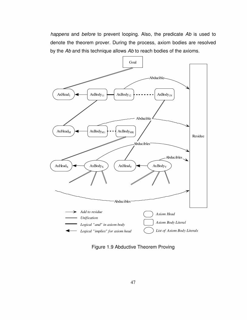
47
happens and before to prevent looping. Also, the predicate Ab is used to
denote the theorem prover. During the process, axiom bodies are resolved
by the Ab and this technique allows Ab to reach bodies of the axioms.
Goal
AxHead1 AxBody11 AxBody1N
AxHeadM AxBodyM 1 AxBodyMK
Residue
AxBody12
Abducible
Abducible
AxHeadX AxBodyX AxHeadY AxBodyY
Abducibles
Abducibles
Abducibles
Add to residue
Unification
Logical "and" in axiom body
Logical " implies" for axiom head
Axiom Head
Axiom Body Literal
List of Axiom Body Literals
Figure �1.9 Abductive Theorem Proving
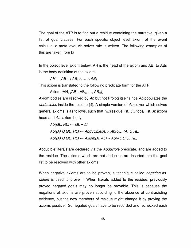
48
The goal of the ATP is to find out a residue containing the narrative, given a
list of goal clauses. For each specific object level axiom of the event
calculus, a meta-level Ab solver rule is written. The following examples of
this are taken from [�5].
In the object level axiom below, AH is the head of the axiom and AB1 to ABN
is the body definition of the axiom:
AH � AB1 ∧ AB2 ∧ … ∧ AB3
This axiom is translated to the following predicate form for the ATP:
Axiom (AH, {AB1, AB2, …, ABN})
Axiom bodies are resolved by Ab but not Prolog itself since Ab populates the
abducibles inside the residue [�5]. A simple version of Ab solver which solves
general axioms is as follows, such that RL:residue list, GL: goal list, A: axiom
head and AL: axiom body:
Ab(GL, RL) � GL = ∅
Ab({A} U GL, RL) � Abducible(A) ∧ Ab(GL, {A} U RL)
Ab({A} U GL, RL) � Axiom(A, AL) ∧ Ab(AL U G, RL)
Abducible literals are declared via the Abducible predicate, and are added to
the residue. The axioms which are not abducible are inserted into the goal
list to be resolved with other axioms.
When negative axioms are to be proven, a technique called negation-as-
failure is used to prove it. When literals added to the residue, previously
proved negated goals may no longer be provable. This is because the
negations of axioms are proven according to the absence of contradicting
evidence, but the new members of residue might change it by proving the
axioms positive. So negated goals have to be recorded and rechecked each
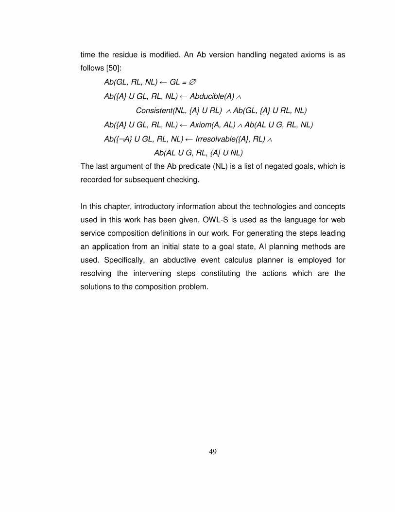
49
time the residue is modified. An Ab version handling negated axioms is as
follows [�50]:
Ab(GL, RL, NL) � GL = ∅
Ab({A} U GL, RL, NL) � Abducible(A) ∧
Consistent(NL, {A} U RL) ∧ Ab(GL, {A} U RL, NL)
Ab({A} U GL, RL, NL) � Axiom(A, AL) ∧ Ab(AL U G, RL, NL)
Ab({¬A} U GL, RL, NL) � Irresolvable({A}, RL) ∧
Ab(AL U G, RL, {A} U NL)
The last argument of the Ab predicate (NL) is a list of negated goals, which is
recorded for subsequent checking.
In this chapter, introductory information about the technologies and concepts
used in this work has been given. OWL-S is used as the language for web
service composition definitions in our work. For generating the steps leading
an application from an initial state to a goal state, AI planning methods are
used. Specifically, an abductive event calculus planner is employed for
resolving the intervening steps constituting the actions which are the
solutions to the composition problem.
50
CHAPTER 3
EVENT CALCULUS AND WEB SERVICE COMPOSITION
The event calculus, described in the previous chapter, serves as the
framework for representing the web service compositions and applying
abductive theorem proving techniques. In this chapter, methods for achieving
these issues will be investigated.
3.1 Architecture of the System
In our system, generic web service composition definitions are taken, and
they are translated to event calculus domain for finding the possible plan set
with the abductive planner. A subset of OWL-S ontology is used as the
language for the generic composition definition. The generic composition
definition is translated to event calculus axioms in Prolog language as
compound events. The abductive planner in event calculus generates the
plans which would lead the user to the desired goal on execution. Figure 3.1
shows the architecture of our system graphically
In the planning process, the planner is in a continuous interaction with the
real world to get the available services which can be used in the plan in order
to achieve the goal. The plan acquires its structure step by step with this

51
information on the discovered services. In a single step of planning, a
separate plan is generated for each discovered service for the step in
question. The list of generated plans is then presented to the user in an
interactive graphical user interface for selection of the preferred plan for
execution. The preferred plan is then executed with the parameters provided
by the user, and the goal is reached.
Figure �3.1 The System Architecture
The web service discovery and execution parts are out of the scope of this
thesis, so only primitive structures are implemented for them in this thesis.
The translation from OWL-S to event calculus will be explained in Chapter
IV, and the implementation details of this architecture are explained in
Chapter V. In this chapter, it will be shown how abductive planning
capabilities of the event calculus can be used to solve the web service
composition problem.
3.2 Advantages of Using Event Calculus
The planning problem in the event calculus is formulated in simple terms as
follows [�14]: Given the domain knowledge containing possible events in that
52
domain and how the fluents are affected from those events (i.e. a conjunction
of specific axioms happens, initiates, terminates for that domain), the event
calculus axioms (i.e. holdsAt, clipped, declipped) and a goal state (e.g.
holdsAt(f,t)), the abductive theorem prover generates the plan which is a
conjunction of (i.e. abducible literals) time stamped happens predicates and
temporal ordering predicates. The event calculus provides an elegant way to
represent the changes of the world through actions. The choice of event
calculus as the domain for planning is motivated by both practical and formal
needs, and gives several advantages. The primary advantage is that, the
event calculus ontology has the necessary properties and components to
represent a generic composition description, making it possible to map the
description to the logical representation in its domain. The event calculus
ontology includes an explicit time structure that enables it to express the
temporal ordering of the events included in the composition. It is possible to
represent totally ordered or partially ordered sets of events with the capability
to express concurrency, or sequential ordering of events. Another advantage
is that, the semantics of non-functional requirements can be represented in
event calculus enabling the transfer of preconditions/effects of web services
involved in the composition. Also, it is possible to define conditional
constructs for the representation of conditional components belonging to the
generic composition definition. So, in this thesis the abductive event calculus
planner (ATP) described in [�50], and extended in [�5] will be used for
representing the generic composition definition and generating a composite
process as the output of planning.
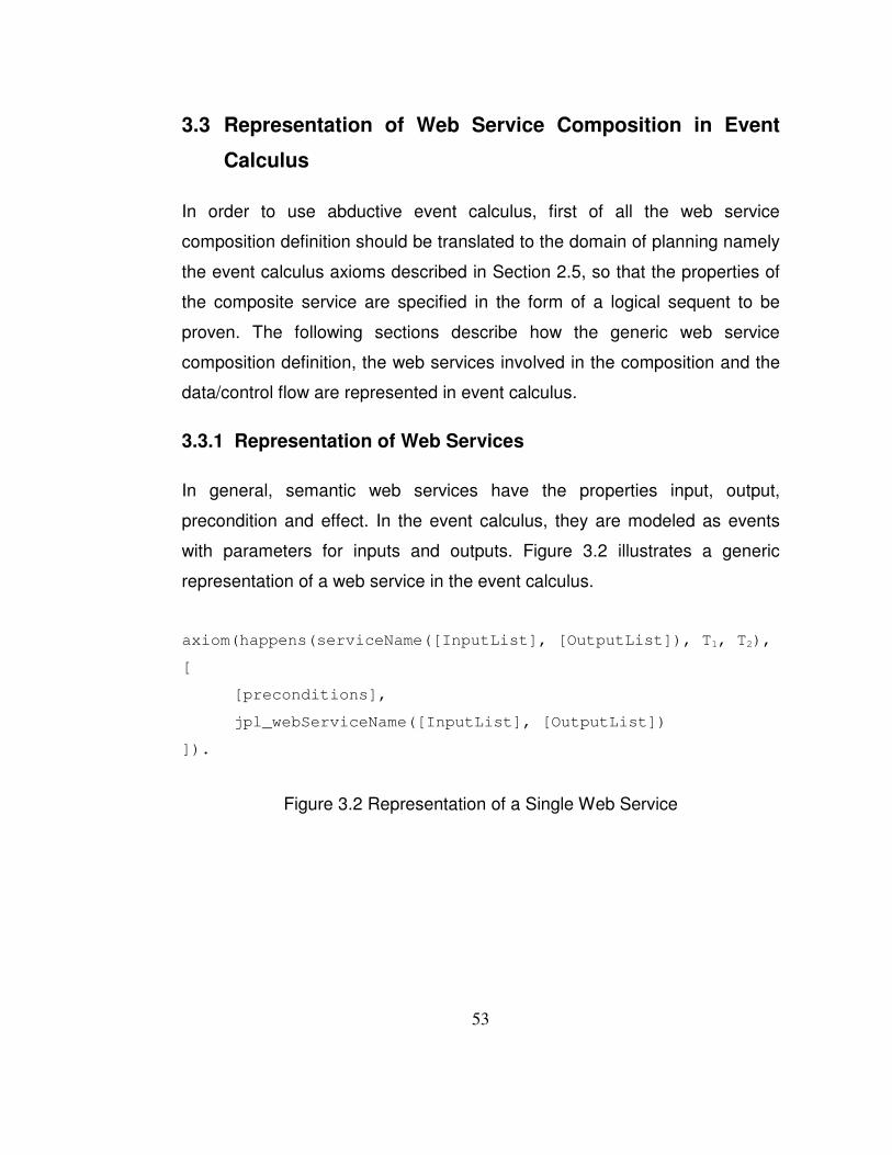
53
3.3 Representation of Web Service Composition in Event
Calculus
In order to use abductive event calculus, first of all the web service
composition definition should be translated to the domain of planning namely
the event calculus axioms described in Section 2.5, so that the properties of
the composite service are specified in the form of a logical sequent to be
proven. The following sections describe how the generic web service
composition definition, the web services involved in the composition and the
data/control flow are represented in event calculus.
3.3.1 Representation of Web Services
In general, semantic web services have the properties input, output,
precondition and effect. In the event calculus, they are modeled as events
with parameters for inputs and outputs. Figure 3.2 illustrates a generic
representation of a web service in the event calculus.
axiom(happens(serviceName([InputList], [OutputList]), T1, T2),
[
[preconditions],
jpl_webServiceName([InputList], [OutputList])
]).
Figure �3.2 Representation of a Single Web Service
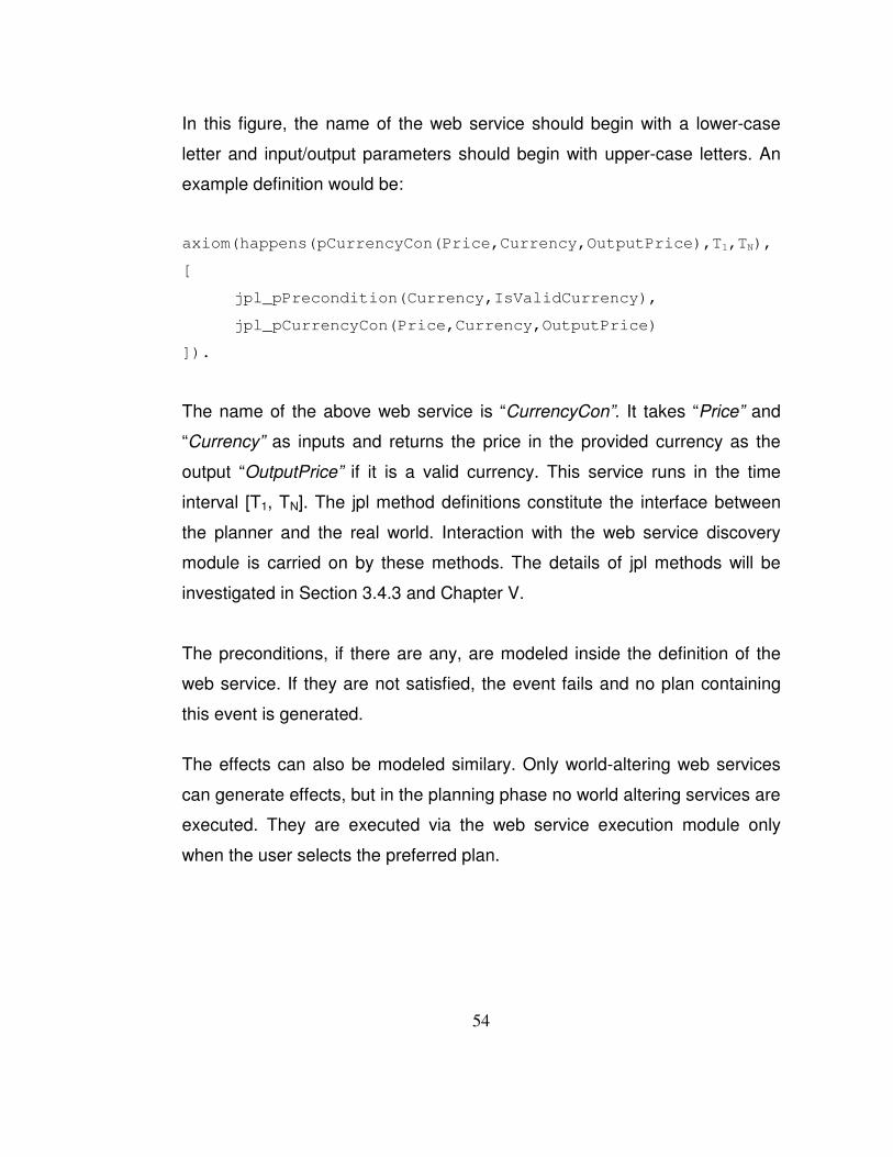
54
In this figure, the name of the web service should begin with a lower-case
letter and input/output parameters should begin with upper-case letters. An
example definition would be:
axiom(happens(pCurrencyCon(Price,Currency,OutputPrice),T1,TN),
[
jpl_pPrecondition(Currency,IsValidCurrency),
jpl_pCurrencyCon(Price,Currency,OutputPrice)
]).
The name of the above web service is “CurrencyCon”. It takes “Price” and
“Currency” as inputs and returns the price in the provided currency as the
output “OutputPrice” if it is a valid currency. This service runs in the time
interval [T1, TN]. The jpl method definitions constitute the interface between
the planner and the real world. Interaction with the web service discovery
module is carried on by these methods. The details of jpl methods will be
investigated in Section 3.4.3 and Chapter V.
The preconditions, if there are any, are modeled inside the definition of the
web service. If they are not satisfied, the event fails and no plan containing
this event is generated.
The effects can also be modeled similary. Only world-altering web services
can generate effects, but in the planning phase no world altering services are
executed. They are executed via the web service execution module only
when the user selects the preferred plan.
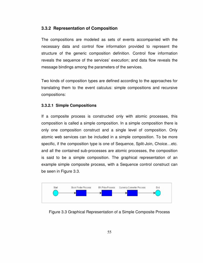
55
3.3.2 Representation of Composition
The compositions are modeled as sets of events accompanied with the
necessary data and control flow information provided to represent the
structure of the generic composition definition. Control flow information
reveals the sequence of the services’ execution; and data flow reveals the
message bindings among the parameters of the services.
Two kinds of composition types are defined according to the approaches for
translating them to the event calculus: simple compositions and recursive
compositions:
3.3.2.1 Simple Compositions
If a composite process is constructed only with atomic processes, this
composition is called a simple composition. In a simple composition there is
only one composition construct and a single level of composition. Only
atomic web services can be included in a simple composition. To be more
specific, if the composition type is one of Sequence, Split-Join, Choice…etc.
and all the contained sub-processes are atomic processes, the composition
is said to be a simple composition. The graphical representation of an
example simple composite process, with a Sequence control construct can
be seen in Figure 3.3.
Figure �3.3 Graphical Representation of a Simple Composite Process

56
In Figure3.3, the simple composite web service is named “BookPrice” and it
gives the price of a book in the desired currency. It is composed of three
atomic web services which are supposed to run sequentially. The first
service finds the ISBN of the book whose name is provided by the user, the
second service finds the price of the book with the provided ISBN from the
first service, and the third service converts the found price to the desired
currency.
In the event calculus, a simple composite process is modeled as a
compound event which contains the declarations of the participating atomic
web services as simple events. The atomic web services are declared in a
timely fashion for expressing control flow according to the type of
composition. The definitions of atomic web services should also be added to
the model as individual events as described in the previous section.
An example axiom for a simple process definition in the event calculus is as
follows:
axiom(happens(pBookPrice(Currency, BookName), T1, TN),
[
happens(pBookFinder(BookName, BookInfo), T2, T2),
happens(pBNPrice(BookInfo, Price), T3, T3),
happens(pCurrencyCon(Price, Currency, OutPrice),T4, T4),
before(T1, T2),
before(T2, T3),
before(T3, T4),
before(T4, TN)
]).
Figure �3.4 Representation of A Simple Composition

57
The events for individual services, i.e “pBookFinder”, “pBNPrice” and
“pCurrencyCon” and relevant jpl methods should also be defined as in Figure
3.2.
3.3.2.2 Recursive Compositions
If a composite process includes another composite process as one of its
subprocesses, then this composition is called a recursive composition. In
recursive compositions, there are multiple levels of composite processes in
contrast to simple compositions. The graphical representation of an example
recursive composite process can be seen in Figure 3.5.
Figure �3.5 Graphical Representation of a Recursive Composite Process
In Figure 3.5, the main, or the outermost composition is the recursive
composition structured according to the composition control construct
Sequence containing four more compositions: one Split-Join (marked with
pink), one If-Then-Else (marked with yellow), and two other Sequence
(marked with arrows) types. The blue recktangles represent the atomic
services.
In a simple composition there is only one composite axiom representing the
composite event, whereas in the recursive composition there are as many

58
composite axioms as the composite process count. Each composite process
should be axiomatized according to its type and the indvidual processes
contained in it. The axiom for the recursive composition includes the
declarations of the contained atomic and/or composite web services. Each
contained composite process should also be axiomatized in a recursive
fashion until there remain only atomic web services to be represented as
individual events.
The structure of the axioms for recursive compositions is the same as the
simple one’s depicted in Figure 3.4. The only difference between the
representations is that, for the recursive compositions, the contained axioms
corresponding to the contained composite web services also need to be
defined as the main recursive composition axiom. The details and examples
will be provided in Chapter V.
3.3.3 Representation of Control Flow
In the event calculus, the temporal relationships between the web services
defining the flow of control of the generic composition definition are
represented by the predicate before. As the name implies, “before (T1, T2)”
means that T1 is a former timestamp in timeline than T2. It is possible to
model sequential and concurrent activities with this predicate. This enables
the total and partial ordering of events for the planning process. Also it is
possible to represent conjunctions, disjunctions and temporal iterations as
well [�48].
There are two types of events according to their durations. First group
contains events occuring in an instant and do not have a significant duration.
They are represented as:

59
happens(E1, T1) or
happens(E1, T1, T1)
Second group contains the events having a duration bounded by start and
finish times of the event, and are represented as:
happens(E1, T1, T2).
For the second group the predicate before (T1, T2) is included implicitly.
There is no need to define it again.
3.3.3.1 Modelling Sequential Activities
The sequential activity is modeled as follows for the first and second groups.
For the first group:
happens(E1, T1),
happens(E2, T2),
before(T1, T2)
For the second group:
happens(E1, T1, T2),
happens(E2, T3, T4),
before(T2, T3)
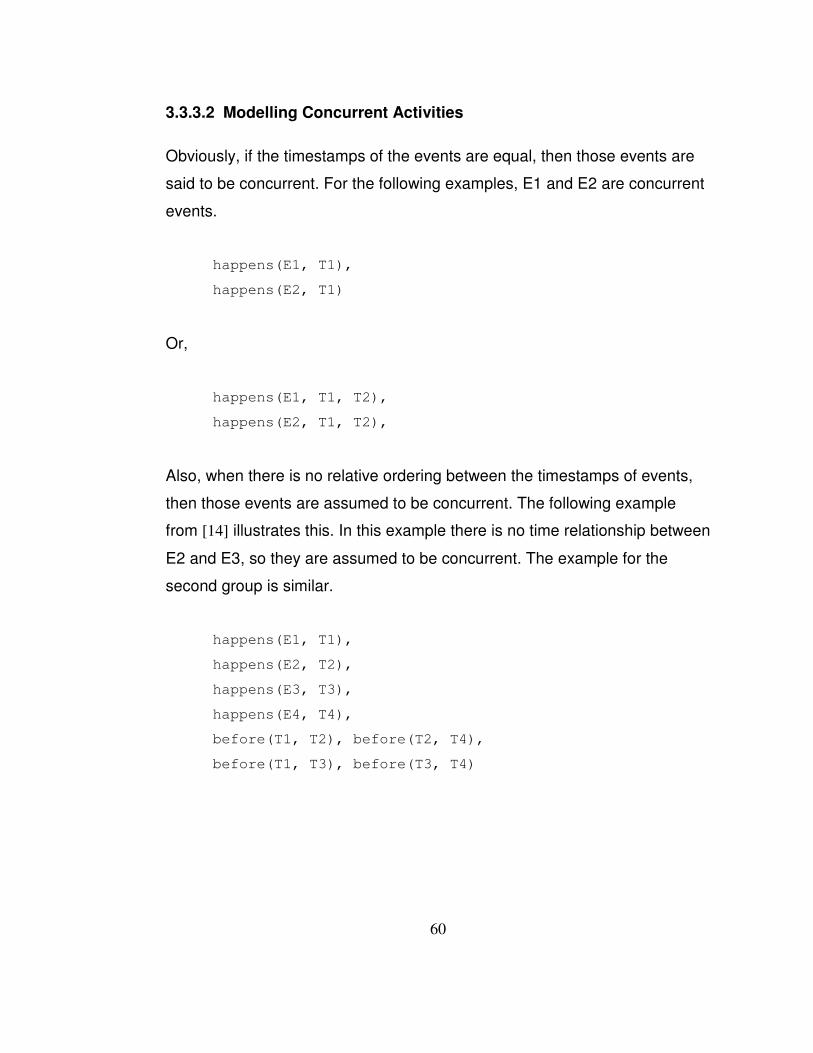
60
3.3.3.2 Modelling Concurrent Activities
Obviously, if the timestamps of the events are equal, then those events are
said to be concurrent. For the following examples, E1 and E2 are concurrent
events.
happens(E1, T1),
happens(E2, T1)
Or,
happens(E1, T1, T2),
happens(E2, T1, T2),
Also, when there is no relative ordering between the timestamps of events,
then those events are assumed to be concurrent. The following example
from [�14] illustrates this. In this example there is no time relationship between
E2 and E3, so they are assumed to be concurrent. The example for the
second group is similar.
happens(E1, T1),
happens(E2, T2),
happens(E3, T3),
happens(E4, T4),
before(T1, T2), before(T2, T4),
before(T1, T3), before(T3, T4)

61
3.3.4 Representation of Data Flow Between Web Services
As a result of web service compositions’ nature, outputs of atomic or
composite processes can be the inputs of other processes in the
composition. The individual web services comprised in the composition
operate as autonomous and separate entities being executed on the servers
they are hosted and they are not subject to a form of centralized monitoring.
But the composition itself is supposed to be executed by the client owning
the composition. As a result, the wiring of the input/output parameters
between the atomic or composite web services should be handled also in the
side owning the composition.This is necessary in order not to lose the path
for the flow of data between the services and invoke the services with the
inputs dynamically obtained in the runtime.
In the event calculus, this data flow is handled via parameter names of the
events. In a specific axiom, all the variable names which point to a certain
value should have the same name. For example, in Figure 3.4, the second
input parameter “BookName” of the composite service “pBookPrice” is used
also as the input for “pBookFinder” process. The same naming of the
parameter ensures that the input of the composite process “pBookPrice” will
be provided to the process “pBookFinder” as its input. Also, the parameter
“BookInfo” is declared both in “pBookFinder” and “pBNPrice” processes. This
means the output of the first process “BookInfo” will be the input of the
second process.
Using the techniques described in this section, a comprehensive
representation of the generic composition definition in the event calculus can
be maintained. Having this representation in hand, it is possible to apply the
abductive planning techniques for generating the list of possible plans for the

62
generic composition. The following section describes how the planning is
accomplished for a composition defined in event calculus.
3.4 Plan Generation with Abductive Theorem Prover (ATP)
In this thesis, the Abductive Theorem Prover is used as a planner in the
event calculus framework in the planning phase. The theoretical grounding of
planning with ATP has been given in Section 2.6. In this section, the
advantages of using ATP and an example illustrating how the plans are
generated with it will be presented in addition to some issues about planning
in our tool.
3.4.1 Advantages of ATP
The advantages of ATP can be summarized as follows [�51]: It supports
reasonably complex event calculus plans. It tackles the issue of hierarchical
planning. The event calculus formalism used is not just a logic program, but
is specified in first-order predicate calculus augmented with circumscription.
It can handle actions with context-dependent effects; and since it uses
abduction to solve initiates and terminates goals, the planner is both sound
and complete.
3.4.2 Plan Generation Example
A simple example showing how abduction can be used in planning will be
shown here. With the use of abduction, the planner generates a sequence of
actions leading from an initial state to a final state.

63
In the example from [�39], given that Nathan was not awake and then he was
awake, it is possible to abduce that he woke up with ATP. In order to perform
abduction with ATP, first a file containing the relevant event calculus axioms
are created. In our case the file, named sleep.pl contains the following:
axiom(initiates(wake_up(X),awake(X),T),[]).
axiom(terminates(fall_asleep(X),awake(X),T),[]).
axiom(initially(neg(awake(nathan))),[]). abducible(dummy).
executable(wake_up(X)). executable(fall_asleep(X)).
Then Prolog is started and event calculus planner and sleep.pl files are
consulted (loaded) to it. Then the following query is issued to Prolog:
abdemo([holds_at(awake(nathan),t)],R).
Given the above axioms and goal, the event calculus planner produces the
following plan:
R = [[happens(wake_up(nathan), t1, t1)], [before(t1, t)]]
It is found out by abduction that, Nathan should perform the action
“wake_up” before time t in order to satisfy the situation that he was awake at
time t.
3.4.3 Communication with the Real World
In the planning process, the planner is in a continuous interaction with the
real world to get the available services which can be used in the plan in order
to achieve the goal. Since the plan generation is a dynamic process, in every
step of the planning process where an atomic web service is to be

64
processed, there needs to be an interaction with the real world to get the
information about the discovered services. The interaction is with the web
service discovery module, which, in theory, takes the semantic descriptions
of atomic web services included in the generic composition definition, and
returns the set of convenient and available web services as a result of its
internal discovery mechanism. This communication is achieved through jpl
method definitions, that provide an interface between the planning process
and the discovery module. There is a single jpl method for each event
representing an atomic web service. That single jpl method manages all the
necessary data transfers and transformations. It provides the semantic
information of the services needed by the planner, provided the inputs are
taken from the user. The plans are generated and listed with this gathered
information including service name and parameters.
Once the user selects the preferred plan, the next phase of planning begins.
In this phase, the information providing services included in the selected plan
are executed, and the results are shown to the user. This execution is also
handled via jpl calls. The jpl method definitions handle the case where there
is more than one output of the atomic service description, and also there is
more than one web service found by the discovery module for the event in
question. This dynamic structure will presented in Chapter V.
3.4.4 Service Execution During Planning
In the plan generation phase, the inputs defined in the generic composition
definition are provided by the user and the outputs of the individual atomic
services are taken after the execution of the found services provided by the
discovery module. The services executed in the planning phase and guiding

65
the plan generation process are only information-providing web services. The
world-altering services are not executed, because changing the state of the
world would result in unwanted harm unless the plan in question is not
selected by the user for execution. For example, it may be desired querying
the price of a book from a set of web services in order to find the cheapest
one, but buying the book, which has a world-altering effect, needs
confirmation from the user. The plan containing the step for buying the book
should be selected by the user explicitly and confirmed for execution.
When there are multiple services found by the discovery engine, a separate
plan for each of them is generated. Also, for multiple steps having multiple
discovered services, combinations of the found services are taken. Consider
the following generic composition definition given in Figure 3.7. This
composition is a simple composition having “Any-Order” structure as the
control construct. In this service, the execution order of the services does not
matter, so plans including the found services in any order are valid.
Figure �3.6 Simple Composition with Any-Order Control Construct
For this composition, assume that there are two services found for the “Zip
Code Finder Process” Z1, Z2; and one service for the “Book Finder Process”

66
B1. In this case, ATP will generate plans including Z1 and B in any order, and
also including Z2 and B in any order. There will be four plans as folows:
Plan 1 - Step 1: B, Step 2: Z1
Plan 2 - Step 1: B, Step 2: Z2
Plan 3 - Step 1: Z1, Step 2: B
Plan 4 - Step 1: Z2, Step 2: B
In this chapter, the plan generation phase with the generic composition
definition provided in event calculus has been explained. But in our system,
generic compositions are defined in OWL-S. The composition structure as
well as the user constraints should be declared in OWL-S files and provided
to our system. Next chapter presents the methods for translating generic
compositions in OWL-S to the event calculus domain.

67
CHAPTER 4
OWL-S TO EVENT CALCULUS TRANSLATION
In our system, a subset of OWL-S ontology is used as the language for
generic composition definitions, which are the specifications for how to
compose a sequence of atomic process executions. It is possible to define
the composition abstractly using the process model part of OWL-S. The
grounding information is not needed in our system, since the exact services
will be discovered and provided by the service discovery module. The profile
part is not needed either, but it would be beneficial for the discovery module.
The abstraction mechanism of OWL-S helps service discovery engines to
easily understand the properties of the composition. The advantage of using
OWL-S is that, it is possible to express the composition structure and the
interaction scenarios of the services (data/control flow) as well as the
necessary information for the discovery of the composite service and the
atomic services included in the composition. The generic composite services
are translated to event calculus axioms automatically with our tool. In this
chapter, we will show how to encode a composite process composition
problem as an abductive event calculus planning problem, so that our tool
can be used with OWL-S web services descriptions to automatically
generate a composition of web services calls.

68
4.1 Translation of the Goal State
A plan is a set of events resulting in the goal state on execution. The plans
are returned by the planner as answers to the query declaring the goal state.
The query for the abductive theorem prover, stating the goal situation is
defined as an event calculus axiom as follows.
abdemo([holds_at(pCompositeProcessPlanned(InputList), t)], R).
Here, the lower-case letter “p” is added as a prefix to the name since the
predicates should begin with a lower-case letter. Also, the word “Planned” is
attached to the name of the composite process as a suffix. It could be
another word either; the point here is that the name should be different from
the original process name.
This query reveals the set of plans which satisfy the
“pCompositeProcessPlanned” predicate at time t with the input list (InputList)
of the composite process provided by the user. An actual query example
would be as follows.
abdemo([holds_at(pBookPriceProcessPlanned('YTL',
'Madam Bovary'),t)],R).
The predicate “pCompositeProcessPlanned” is a construct for linking the
goal state to the main process axiom. It is used as follows:
initiates(pCompositeProcess(InputList), pCompositeProcessPlanned(InputList), T).
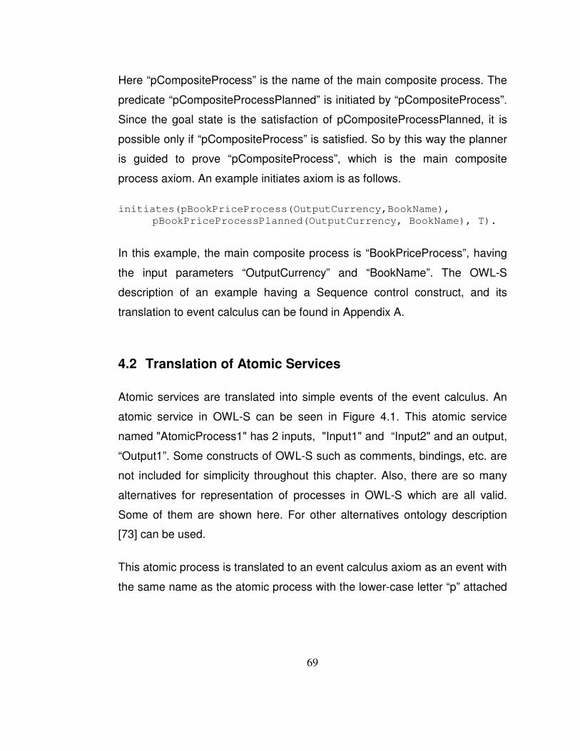
69
Here “pCompositeProcess” is the name of the main composite process. The
predicate “pCompositeProcessPlanned” is initiated by “pCompositeProcess”.
Since the goal state is the satisfaction of pCompositeProcessPlanned, it is
possible only if “pCompositeProcess” is satisfied. So by this way the planner
is guided to prove “pCompositeProcess”, which is the main composite
process axiom. An example initiates axiom is as follows.
initiates(pBookPriceProcess(OutputCurrency,BookName),
pBookPriceProcessPlanned(OutputCurrency, BookName), T).
In this example, the main composite process is “BookPriceProcess”, having
the input parameters “OutputCurrency” and “BookName”. The OWL-S
description of an example having a Sequence control construct, and its
translation to event calculus can be found in Appendix A.
4.2 Translation of Atomic Services
Atomic services are translated into simple events of the event calculus. An
atomic service in OWL-S can be seen in Figure 4.1. This atomic service
named "AtomicProcess1" has 2 inputs, "Input1" and “Input2" and an output,
“Output1”. Some constructs of OWL-S such as comments, bindings, etc. are
not included for simplicity throughout this chapter. Also, there are so many
alternatives for representation of processes in OWL-S which are all valid.
Some of them are shown here. For other alternatives ontology description
[�73] can be used.
This atomic process is translated to an event calculus axiom as an event with
the same name as the atomic process with the lower-case letter “p” attached

70
as a prefix. The inputs and outputs of the process are the parameters of the
event with upper-case letters.
<process:AtomicProcess rdf:ID="AtomicProcess1"> <rdfs:label> AtomicProcess1 </rdfs:label> <process:hasInput> <process:Input rdf:ID="Input1">
<process:parameterType rdf:datatype="&xsd;#anyURI">&xsd;#string
</process:parameterType> </process:Input> </process:hasInput> <process:hasInput>
<process:Input rdf:ID="Input2"> <process:parameterType rdf:datatype="&xsd;#anyURI">&xsd;#string </process:parameterType> </process:Input>
</process:hasInput> <process:hasOutput>
<process:Output rdf:ID="Output1 "> <process:parameterType rdf:datatype="&xsd;#anyURI">&xsd;#string </process:parameterType> </process:Output>
</process:hasOutput> </process:AtomicProcess>
Figure �4.1 OWL-S Representation of an Atomic Service
The inputs of the event are instantiated with the inputs provided by the user,
and outputs are the results of the execution of the actual information-
providing services. The time interval in which the service is active is
described by the time tags “T1, TN” which are the last two parameters. They
are used to cache results for operations. If operations are not cached
according to their time points then different effect axioms of the same atomic

71
process would be associated with different outputs which might result
conflicting effects when the world altering web service operations are
invoked to collect outputs [�14]. The translation of the atomic process in
Figure 4.1 can be seen in Figure 4.2.
axiom(happens(pAtomicProcess1(Input1,Input2,Output1),T1, TN),
[
jpl_pAtomicProcess1(Input1,Input2,Output1)
]).
Figure �4.2 Event Calculus Representation of an Atomic Service
4.3 Translation of Composite Services
Composite processes are composed of subprocesses, and specify
constraints on the ordering and conditional execution of the subprocesses.
The constraints are captured by the “composedOf" property in OWL-S, which
is required for a composite process [�73], and they are similar to standard
workflow structures. Composite processes are constructed using control
constructs and references to processes are called “Perform”s in OWL-S
ontology. Performs may be references to atomic or composite processes,
and they are composed using other “ControlConstruct”s. The minimal initial
set of control constructs according to [�73] includes Sequence, Split, Split +
Join, Any-Order, Condition, If-Then-Else, Iterate, Repeat-While and Repeat-
Until. These constructs are translated into compound events in the event
calculus framework. The subprocesses in a composition can be either atomic
or composite processes. So, the translation of the control constructs is
recursively applied to the processes until all composite processes are
replaced with the corresponding axioms that contain atomic processes as

72
stated in [�14]. The translation of some of the flow control constructs into the
event calculus axioms is presented in the following sections. The Repeat-
While and Repeat-Until constructs are not within the scope of this thesis, so
their translations are not included. The abstract and more generic
formulations for the translations can be found in [�5].
4.3.1 Translation of the Sequence Control Construct
When the Sequence construct is used, all the sub-processes contained in it
are to be executed sequentially in order. An example composite process
definition containing a Sequence control construct can be seen in Figure 4.3.
There two sub-processes in this definition. The inputs, outputs, bindings and
some other OWL-S constructs are omitted for simplicity. A real composition
including most of the control constructs with their comprehensive definitions
can be found in Appendix B.
The translation is accomplished through the use of compound events in the
event calculus which contain sub-events [�14]. The sequence of events is
triggered from the body of the compound event and the ordering between
them is ensured with the “before” predicate, satisfying the ordering in the
OWL-S definition. The event calculus axiom which is the translation of the
composition in Figure 4.3 is given in Figure 4.4.
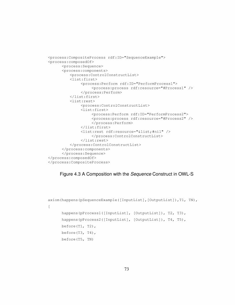
73
<process:CompositeProcess rdf:ID="SequenceExample"> <process:composedOf>
<process:Sequence> <process:components> <process:ControlConstructList> <list:first> <process:Perform rdf:ID="PerformProcess1"> <process:process rdf:resource="#Process1" /> </process:Perform> </list:first> <list:rest> <process:ControlConstructList> <list:first> <process:Perform rdf:ID="PerformProcess2"> <process:process rdf:resource="#Process2" /> </process:Perform> </list:first> <list:rest rdf:resource="&list;#nil" /> </process:ControlConstructList> </list:rest> </process:ControlConstructList> </process:components> </process:Sequence>
</process:composedOf> </process:CompositeProcess>
Figure �4.3 A Composition with the Sequence Construct in OWL-S
axiom(happens(pSequenceExample([InputList],[OutputList]),T1, TN),
[
happens(pProcess1([InputList], [OutputList]), T2, T3),
happens(pProcess2([InputList], [OutputList]), T4, T5),
before(T1, T2),
before(T3, T4),
before(T5, TN)

74
]).
Figure �4.4 Translation of Sequence to Event Calculus
4.3.2 Translation of the Any-Order Control Construct
According to the OWL-S process ontology, Any-Order control construct
allows the sub-processes contained in it to be executed in some unspecified
order but not concurrently. The sub-processes are specified in a structure
named “ControlConstructBag”. Execution and completion of all components
is required. The execution of processes in an Any-Order construct cannot
overlap, i.e. atomic processes cannot be executed concurrently and
composite processes cannot be interleaved. An example composition with
Any-Order construct can be seen in Figure 4.5.
<process:CompositeProcess rdf:ID="AnyOrderExample"> <process:composedOf>
<process:Any-Order> <process:components> <process:ControlConstructBag> <list:first>
<process:Perform rdf:ID="PerformProcess1"> <process:process rdf:resource="#Process1" /> </process:Perform>
</list:first> <list:rest>
<process:ControlConstructList> <list:first> <process:Perform rdf:ID="PerformProcess2">
<process:process rdf:resource="#Process2" /> </process:Perform>
</list:first> <list:rest rdf:resource="&list;#nil" /> </process:ControlConstructList> </list:rest> </process:ControlConstructBag>
</process:components> </process:Any-Order>
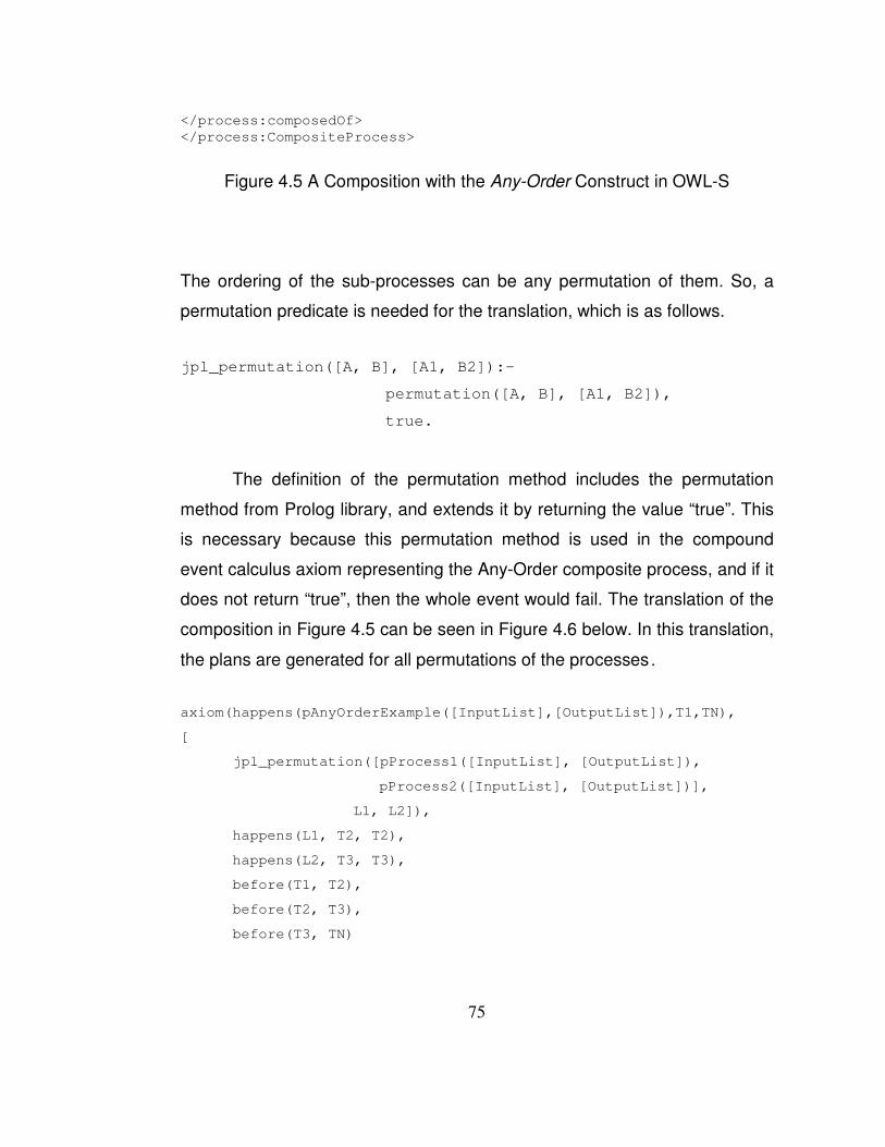
75
</process:composedOf> </process:CompositeProcess>
Figure �4.5 A Composition with the Any-Order Construct in OWL-S
The ordering of the sub-processes can be any permutation of them. So, a
permutation predicate is needed for the translation, which is as follows.
jpl_permutation([A, B], [A1, B2]):-
permutation([A, B], [A1, B2]),
true.
The definition of the permutation method includes the permutation
method from Prolog library, and extends it by returning the value “true”. This
is necessary because this permutation method is used in the compound
event calculus axiom representing the Any-Order composite process, and if it
does not return “true”, then the whole event would fail. The translation of the
composition in Figure 4.5 can be seen in Figure 4.6 below. In this translation,
the plans are generated for all permutations of the processes.
axiom(happens(pAnyOrderExample([InputList],[OutputList]),T1,TN),
[
jpl_permutation([pProcess1([InputList], [OutputList]),
pProcess2([InputList], [OutputList])],
L1, L2]),
happens(L1, T2, T2),
happens(L2, T3, T3),
before(T1, T2),
before(T2, T3),
before(T3, TN)
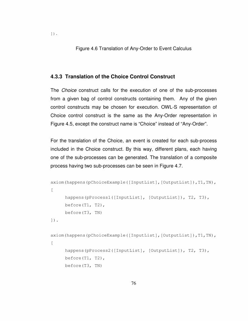
76
]).
Figure �4.6 Translation of Any-Order to Event Calculus
4.3.3 Translation of the Choice Control Construct
The Choice construct calls for the execution of one of the sub-processes
from a given bag of control constructs containing them. Any of the given
control constructs may be chosen for execution. OWL-S representation of
Choice control construct is the same as the Any-Order representation in
Figure 4.5, except the construct name is “Choice” instead of “Any-Order”.
For the translation of the Choice, an event is created for each sub-process
included in the Choice construct. By this way, different plans, each having
one of the sub-processes can be generated. The translation of a composite
process having two sub-processes can be seen in Figure 4.7.
axiom(happens(pChoiceExample([InputList],[OutputList]),T1,TN),
[
happens(pProcess1([InputList], [OutputList]), T2, T3),
before(T1, T2),
before(T3, TN)
]).
axiom(happens(pChoiceExample([InputList],[OutputList]),T1,TN),
[
happens(pProcess2([InputList], [OutputList]), T2, T3),
before(T1, T2),
before(T3, TN)
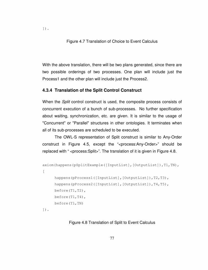
77
]).
Figure �4.7 Translation of Choice to Event Calculus
With the above translation, there will be two plans generated, since there are
two possible orderings of two processes. One plan will include just the
Process1 and the other plan will include just the Process2.
4.3.4 Translation of the Split Control Construct
When the Split control construct is used, the composite process consists of
concurrent execution of a bunch of sub-processes. No further specification
about waiting, synchronization, etc. are given. It is similar to the usage of
"Concurrent" or "Parallel" structures in other ontologies. It terminates when
all of its sub-processes are scheduled to be executed.
The OWL-S representation of Split construct is similar to Any-Order
construct in Figure 4.5, except the “<process:Any-Order>” should be
replaced with “ <process:Split>”. The translation of it is given in Figure 4.8.
axiom(happens(pSplitExample([InputList],[OutputList]),T1,TN),
[
happens(pProcess1([InputList],[OutputList]),T2,T3),
happens(pProcess2([InputList],[OutputList]),T4,T5),
before(T1,T2),
before(T1,T4),
before(T1,TN)
]).
Figure �4.8 Translation of Split to Event Calculus

78
As seen in the translation, a Split process immediately completes when the
sub-processes are scheduled, but not already executed. The completion of
executions of them is not waited and it is not checked whether the sub-
processes execute and terminate successfully. Split is somewhat similar to
an asynchronous method call.
4.3.5 Translation of the Split-Join Control Construct
Compositions with the Split-Join construct consist of concurrent execution of
a bunch of sub-processes. Unlike Split construct, it is used for ensuring that
the component processes are completed within the time segment of the
composite process. A Split-Join process waits until all its sub-processes are
completed their executions.
The OWL-S description is similar to the one for Any-Order in Figure 4.5. The
translation of it is given in Figure 4.9.
axiom(happens(pSplitJoinExample([InputList],[OutputList]),T1,TN),
[
happens(pProcess1([InputList],[OutputList]),T2,T3),
happens(pProcess2([InputList],[OutputList]),T4,T5),
before(T1,T2),
before(T1,T4),
before(T3,TN),
before(T5,TN),
]).
Figure �4.9 Translation of Split-Join to Event Calculus

79
The completion of sub-processes within the main axiom's time interval is
ensured by the last two “before” predicates in Figure 4.9.
4.3.6 Translation of the If-Then-Else Control Construct
The If-Then-Else control construct consists of a condition, a “then” and an
optional “else” process. Its semantics is to test the condition, if it is true, do
the then process, if it is false, do the else process if it exists. The OWL-S
description including the if-condition definition defined in SWRL can be seen
in Figure 4.10 and its translation can be seen in Figure 4.11.
<process:CompositeProcess rdf:ID="IfThenElseExample"> <process:composedOf> <process:If-Then-Else> <process:ifCondition>
<expr:SWRL-Condition rdf:resource="#SWRLCondition1"/> </process:ifCondition> <process:then rdf:resource="#ThenProcess"/> <process:else rdf:resource="#ElseProcess"/> </process:If-Then-Else> </process:composedOf>
<expr:SWRL-Condition rdf:ID="SWRLCondition1"> <expr:expressionBody rdf:parseType="Literal"> <swrl:AtomList>
<rdf:first> <swrl:BuiltinAtom> <swrl:builtin rdf:resource="&swrlb;#lessThan" />
<swrl:arguments> <rdf:List>
<rdf:first rdf:resource="#Input1" /> <rdf:rest> <rdf:List> <rdf:first rdf:resource="#Input2" /> <rdf:rest rdf:resource="&rdf;#nil" /> </rdf:List> </swrl:arguments> </swrl:BuiltinAtom> </rdf:first> <rdf:rest rdf:resource="&rdf;#nil" /> </swrl:AtomList> </expr:expressionBody> </expr:SWRL-Condition>

80
</process:CompositeProcess>
Figure �4.10 A Composition with the If-Then-Else Construct in OWL-S
axiom(happens(pIfThenElseExample([InputList],[OutputList]),T1, TN),
[
happens(jpl_pIfCondition([InputList]), T2, T3),
happens(pThenCase([InputList],[OutputList]), T4, T5),
before(T1, T2),
before(T3, T4),
before(T5, TN),
]).
axiom(happens(pIfThenElseExample([InputList],[OutputList]),T1, TN),
[
happens(jpl_pElseCondition([InputList]), T2, T3),
happens(pElseCase([InputList],[OutputList]), T4, T5),
before(T1, T2),
before(T3, T4),
before(T5, TN),
]).
Figure �4.11 Translation of If-Then-Else to Event Calculus
Since in the planning time, the input parameters from the user are not
instantiated with the inputs of the composition, and as a result it is not known
whether the if-condition would hold or not, plans for both possibilities are
generated. Two event calculus axioms are generated for ensuring this: one
for the “then” case and one for the “else” case. This is done to show user the

81
possible execution paths. When the user selects one of the plans from the
list containing plans for all discovered services, s/he in fact declares which
discovered service s/he would prefer. On execution, if the “Then” case is
selected, and the if-condition fails, the execution would fail.
4.4 Translation of the Preconditions
An example precondition definition can be seen in Figure 4.12. In this
precondition, SWRL is chosen as the language for specifying the condition.
The condition is whether Input1 is less-than Input2. The inputs are either
provided by the user or by another service as its outputs. The source of them
are specified by the binding declarations which are not shown here. Those
bindings should be handled before the translation to event calculus, because
the parameters representing the same variables should have the same
names in the event calculus. <process:CompositeProcess rdf:ID="PreconditionExp"> ... <process:hasPrecondition>
<expr:SWRL-Condition rdf:ID="lessThan"> <expr:expressionLanguage rdf:resource="&expr;#SWRL" /> <expr:expressionBody rdf:parseType="Literal"> <swrl:AtomList> <rdf:first> <swrl:BuiltinAtom> <swrl:builtin rdf:resource="&swrlb;#lessThan" /> <swrl:arguments> <rdf:List> <rdf:first rdf:resource="Input1" /> <rdf:rest> <rdf:List> <rdf:first rdf:resource="Input2" /> <rdf:rest rdf:resource="&rdf;#nil" /> </rdf:List> </rdf:rest> </rdf:List> </swrl:arguments> </swrl:BuiltinAtom> </rdf:first> <rdf:rest rdf:resource="&rdf;#nil" /> </swrl:AtomList>

82
</expr:expressionBody> </expr:SWRL-Condition>
</process:hasPrecondition> ... </process:CompositeProcess>
Figure �4.12 A Precondition Example in OWL-S
This precondition is translated to a simple event in event calculus, which is
appended to the beginning of the event to which this precondition belongs. If
the precondition does not hold, the event fails in the first step, so that no plan
containing this event is generated. The translation can be seen in Figure
4.13.
axiom(happens(pPreconditionExp([InputList],[OutputList]),T1, TN),
[
jpl_pPrecondition([InputList]),
...
[Other Event/Events and Temporal Orderings]
...
]).
Figure �4.13 Translation of Precondition to Event Calculus
The body of the precondition is defined in the precondition event as shown in
Figure 4.14.
jpl_pPrecondition ([InputList]):-
atom_number (Input1, Arg1),
atom_number (Input2, Arg2),
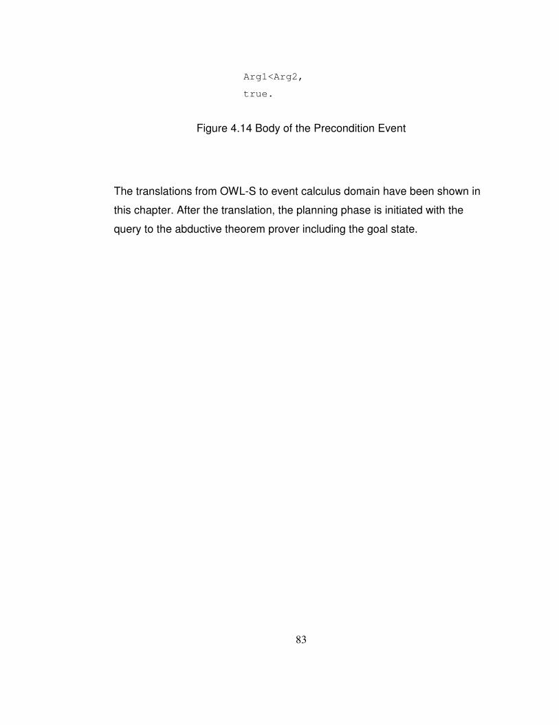
83
Arg1<Arg2,
true.
Figure �4.14 Body of the Precondition Event
The translations from OWL-S to event calculus domain have been shown in
this chapter. After the translation, the planning phase is initiated with the
query to the abductive theorem prover including the goal state.
84
CHAPTER 5
IMPLEMENTATION
The implementation part of our system mostly consists of Java language, as
a web based J2EE application. The front-end is developed using HTML,
JSP, JavaScript and CSS technologies. In the back-end, Java and Prolog
languages are used. The created WAR artifact can be deployed to a J2EE
container; in our case JBoss was used.
For OWL-S parsing, two different parsers -MindSwap's OWL-S API [�63] and
CMU's OWL-S Parser [�70] are used. For the interaction between the Prolog
code and Java code, namely to call Prolog code from within Java, the JPL
library [�68] is used. Java Universal Network/Graph Framework (JUNG) [�69] is
used for the graphical representation of the generic compositions. The
modules of the system are examined in detail below.
5.1 Web Interface
Our system is a web based application, and can be accessible via most
browsers, including Firefox and Internet Explorer. The composition process
in the system is divided into 6 steps with an easy to use HTML front-end.

85
Using the front-end, the user can provide the system with a generic service
composition, see the graphical representation of the composition, select
plans for the composition with matching services, and run a simulated
execution of the given composition with selected services.
Figure 5.1 shows the screen for providing the generic composition. The user
can either upload an OWL-S file or provide the URL of the OWL-S file.
Figure �5.1 OWL-S File/URL Upload Step

86
5.2 OWL-S Parsing
Off-the-shelf OWL-S APIs are used to parse OWL-S files. These APIs are
MindSwap OWL-S API and CMU OWL-S API. The main reason behind using
two libraries is that none of the currently available APIs are able to parse
every type of valid OWL-S document successfully. For instance MindSwap
OWL-S API does not have full support for SWRL expressions, and CMU
OWL-S API can not operate with input-output bindings successfully.
When the user provides a file or a URL of an OWL-S file to the system,
OWL-S parsers are used to parse the given OWL-S documents. For the file
resources MindSwap OWL-S API, for the URL resources, CMU OWL-S API
is used. The aim of parsing is to determine a common, easily navigable and
recursive business model containing all the necessary data for the processes
involved in the composition.
While parsing OWL-S files, the IOPE information is extracted from each of
the participating processes, and added to the Process business object. The
types of the inputs and outputs are also stored within the object. The names
of the inputs and outputs will be changed to reflect input/output bindings in a
future phase.
Apart from IOPE information, each composite process object also contains
composition type information. The business model for the process object is
recursive. Hence a composite process object with the composition type
Sequence has an array of child processes, reflecting the execution order of
the children in the Sequence construct.
87
After parsing OWL-S to generate the process model, the parsers are used to
extract meaningful content for the end-users to see on the front-end. These
include the description of the service composition, the labels for the inputs
outputs, the type of the composition constructs used etc.
5.2.1 OWL-S API
OWL-S API is a library by Maryland Information and Network Dynamics Lab
Semantic Web Agents Project (Mindswap) which provides methods to read
from, write to OWL-S service descriptions. The API also provides a built-in
Service Execution Engine to execute atomic services and certain composite
services with WSDL or UPnP groundings. The supported composite services
are limited to Sequence, Unordered and Split.
OWL-S API has limited support for preconditions and effects. As of version
1.0.1, built-in SWRL parsing is not provided. There are certain cases where
one can reach the same OWL-S class or property by following two different
programmatic paths and face with two different objects, with certain non-
matching fields.
OWL-S parser cannot parse every OWL Full document validated by
WonderWeb OWL Ontology validator [�76] either.
5.2.2 CMU OWL-S API
CMU OWL-S API is a library developed by the Software Agents Group of the
Carnegie Mellon University. CMU OWL-S API provides routines to parse and
88
read the OWL-S service descriptions. As of version 1.1 of the API there's a
solid model tier to navigate through the OWL-S document easily.
Since the model is more intuitive to navigate, creating business objects to
construct Prolog code becomes easier. The API provides routines to parse
OWL-S descriptions located at files, URLs and etc. However the source
stream selection is important, since there are cases where even though the
OWL-S description located at a URL is easily parsed by the API, the same
content cannot be parsed when the source of the stream is a local file.
The problem with CMU OWL-S API is that there's no practical and/or reliable
way of traversing input and output bindings declared in an OWL-S service
description.
There are conflicting libraries between the dependencies of the described
APIs. Therefore the configuration of the implementation becomes important
when both of these libraries are necessary in the same project. In the
implementation phase of this thesis application server's class loader has
been examined and configured properly to operate both libraries within the
application. However a better and easier approach is to opt for only one of
these APIs.
5.3 Graphical Representation
The graphical representation of the composition is necessary to let the user
know what kind of a workflow is to be executed with the given generic
service description. To enable a better viewing experience, a left to right

89
ordering is used, with arrows showing time dependencies and pointing to
nodes from the initial start node, to the end node.
When an arrow is split from a node this means that a Split/Split+Join
construct or an If-Then-Else construct is encountered. In the second case,
the condition stated in the if-condition is parsed and displayed to the user in
a meaningful way, so that the user can understand what will happen if the
generic composition provided is executed. As specified earlier, conditions
can be specified in several logical languages including SWRL, DRS and KIF.
In our implementation, SWRL conditions are supported due to the higher
popularity of the language.
The Java Universal Network/Graph framework JUNG is used to display the
graphical representation. The processes are displayed as vertices in a graph,
and the transitions for the perform structures are displayed as edges. The
graph constructed with JUNG is then exported to a Graphics Interchange
Format (GIF) image and displayed in the browser to the user.
Since one instance of the application might generate multiple files for a
single user or concurrent users, the naming of the GIF files is important in
the web application. The files are named after the id of the session used by
the current user, and the time of image generation request in milliseconds
precision. A sample graphical representation for an If-Then-Else composition
is illustrated in Figure 5.2.

90
Figure �5.2 OWL-S Composition: Graphical Representation Step
5.4 Generation of Prolog code
The generation of Prolog code is the third step in the process of Event
Calculus based Web Service Composition, and is made after the OWL-S file
is parsed. Since there are two different OWL-S parsers, there are also two
different Prolog code generation routines.
5.4.1 Incremental Prolog Code Generator
The first type of Prolog code generator used is an incremental code
generator, and is paired with the MindSwap OWL-S API. The incremental
Prolog generator generates the code as the parser starts parsing the file, and
91
starts embedding Prolog axioms for the processes as the children are
parsed.
For instance, if a process “A” with sequential child processes “C1” and “C2”
are determined, the axiom A containing C1 and C2 is generated right away,
and appended to the buffer. There is no look-ahead approach within the
incremental generator. The Prolog code generated does not change whether
C1 is an atomic process or a composite If-Then-Else statement.
This approach brings certain restrictions on how the compositions and
preconditions are expressed. For instance a precondition for a child process
cannot be placed before the reference to the axiom of the process; it should
be placed within the axiom of the child process. In a similar fashion, If-Then-
Else constructs cannot be externalized to form a relatively flat and easy to
trace code, they should be embedded within the axiom containing the
constructs.
The incremental builder also has several drawbacks in input-output bindings,
since it requires a pre-mapped set of inputs and outputs to work with or an
intelligent code generator which will continuously detect bindings and alter
previously generated code to reflect the actual process.
5.4.2 Process Model Based Prolog Generator
The second type of Prolog code generator is a process model based code
generator, which makes use of an already parsed process to generate the
code, with all the information at hand. This code generator is used with the
CMU OWL-S API.
92
The process model is generated by the CMU OWL-S API as a recursive tree
structure, where the leaves of the tree are the processes, and the branches
of the tree are the transitions between the processes. The preconditions,
input-output bindings and types of the child processes are all known priori
when such a model is used.
The process model based Prolog generator can generate all the static
declarations for axioms and JPL calls at one pass, therefore no additional
passes for the generated code is necessary. The input-output mappings can
be made on the generated process model prior to code generation so that
the generator will not make any additional passes.
The process model based Prolog generator is a more robust code generator
than the incremental code generator, since it works on a pre-processed and
parsed model with more information available at every step.
An individual process object contains a reference to the list of child
processes it has, the inputs and outputs of itself, the composition type of the
process, and the preconditions applicable to the process. The input-output
lists for the composite processes also include inputs and outputs of the child
processes. This is a necessary step since when a child process returns an
output, this output should be made visible to the processes at the same level
as the composite process, and Prolog does not support global variables.
The generated Prolog is displayed to the users on the web interface for
informative purposes as below:

93
Figure �5.3 Prolog Code Display
5.5 Input and Output Bindings
In a web service composition, inputs of atomic or composite processes can
be the outputs of other processes in the composition. For instance, if process
A with inputs i1 and i2 and outputs o1 and o2 is invoked before process B
with inputs i3 and i4 and outputs o3 and o4, and i4 is bound to o2 (the output
of process A), the process B should be invoked with an input dynamically
obtained in the runtime.
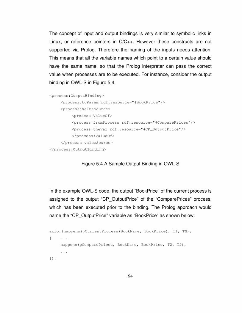
94
The concept of input and output bindings is very similar to symbolic links in
Linux, or reference pointers in C/C++. However these constructs are not
supported via Prolog. Therefore the naming of the inputs needs attention.
This means that all the variable names which point to a certain value should
have the same name, so that the Prolog interpreter can pass the correct
value when processes are to be executed. For instance, consider the output
binding in OWL-S in Figure 5.4.
<process:OutputBinding>
<process:toParam rdf:resource="#BookPrice"/>
<process:valueSource>
<process:ValueOf>
<process:fromProcess rdf:resource="#ComparePrices"/>
<process:theVar rdf:resource="#CP_OutputPrice"/>
</process:ValueOf>
</process:valueSource>
</process:OutputBinding>
Figure �5.4 A Sample Output Binding in OWL-S
In the example OWL-S code, the output “BookPrice” of the current process is
assigned to the output “CP_OutputPrice” of the “ComparePrices” process,
which has been executed prior to the binding. The Prolog approach would
name the “CP_OutputPrice” variable as “BookPrice” as shown below:
axiom(happens(pCurrentProcess(BookName, BookPrice), T1, TN),
[ ...
happens(pComparePrices, BookName, BookPrice, T2, T2),
...
]).

95
Since the names of the variables are changed when the Prolog code is
generated, the inputs and outputs displayed later in the plan display phase
also change. This might lead to misunderstandings on the user side, i.e. the
user who expects an output with the name “reservation_id” would get an
output with the name “output_id”. Different approaches exist for input and
output bindings.
The output bindings are processed in a bottom up manner whereas the input
bindings are processed in a top down manner. The names of the outputs of
the main composition are propagated up. The names of the inputs of sub-
processes are changed based on the names of the outputs of the previously
executed processes. A simple example for variable naming & binding
scenario is provided below:
OWL-S Process Descriptions:
Process A has inputs i1 and i2, and outputs o1 and o2.
Process B has inputs i3 and i4, and outputs o3 and o4.
Composite process C has inputs i5, i6 and i7, and outputs o5, o6, o7.
OWL-S Input & Output Bindings:
The input bindings are between i5 and i1, i6 and i2, i7 and i3, and o1 and i4
The output bindings are between o5 and o2, o6 and o3 and o7 and o4
Prolog Variable Naming:
Process A has inputs i5 and i6, outputs o1 and o5
Process B has inputs i7 and o1, outputs o6 and o7
Composite process C has inputs i5, i6 and i7, and outputs o5, o6, o7

96
5.6 Simple Compositions
Since Prolog does not provide a class structure equivalent to object oriented
languages, handling simple compositions is easier. A sample simple
composition is given in Figure 5.5.
<process:CompositeProcess rdf:about="#BookPriceProcess">
<process:composedOf>
<process:Any-Order>
<process:components>
<process:ControlConstructBag>
<list:first>
<process:Perform rdf:nodeID="Any-Order-Perform1" />
</list:first>
<list:rest>
<process:ControlConstructBag>
<list:first>
<process:Perform rdf:nodeID="Any-Order-Perform2" />
</list:first>
<list:rest rdf:resource="&list;#nil" />
</process:ControlConstructBag>
</list:rest>
</process:ControlConstructBag>
</process:components>
</process:Any-Order>
</process:composedOf>
Figure �5.5 A Simple Composition in OWL-S

97
The above composition is of type Any-Order, and simply references two
atomic processes that can be called with any desired order.
For a simple composition, the generated Prolog code consists of four main
parts: First part contains the static declarations for the Abductive Planner;
second part contains the description of the simple composite process; third
part contains the individual atomic process declarations including their JPL
references; and the last part contains the JPL declarations for the contained
atomic processes
The invocation ordering of the atomic processes is made within the
description of the simple composite process (the second part described
above), based on the type of the composition. A sample ordering is given in
Figure 5.6.
axiom( happens(pSequenceProcess(Input1, Input2, Output), T1, TN),
[ happens(pSequenceProcess1(Input1, OutputP1), T2, T2),
happens(pSequenceProcess2(Input2, OutputP2), T3, T3),
happens(pSequenceProcess3(OutputP1, OutputP2, Output),T4,T4),
before(T1, T2),
before(T2, T3),
before(T3, T4),
before(T4, TN)
] ).
Figure �5.6 A Simple Composition Axiom in Prolog
The above process shows the composite process “pSequenceProcess”
which is formed by three atomic processes, with several input-output
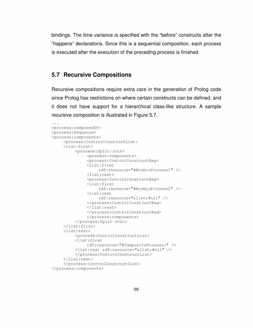
98
bindings. The time variance is specified with the “before” constructs after the
“happens” declarations. Since this is a sequential composition, each process
is executed after the execution of the preceding process is finished.
5.7 Recursive Compositions
Recursive compositions require extra care in the generation of Prolog code
since Prolog has restrictions on where certain constructs can be defined, and
it does not have support for a hierarchical class-like structure. A sample
recursive composition is illustrated in Figure 5.7. ... <process:composedOf> <process:Sequence> <process:components> <process:ControlConstructList> <list:first> <process:Split-Join> <process:components> <process:ControlConstructBag> <list:first rdf:resource="#AtomicProcess1" /> <list:rest> <process:ControlConstructBag> <list:first rdf:resource="#AtomicProcess2" /> <list:rest rdf:resource="&list;#nil" /> </process:ControlConstructBag> </list:rest> </process:ControlConstructBag> </process:components> </process:Split-Join> </list:first> <list:rest> <process:ControlConstructList> <list:first rdf:resource="#CompositeProcess1" /> <list:rest rdf:resource="&list;#nil" /> </process:ControlConstructList> </list:rest> </process:ControlConstructList> </process:components>

99
</process:Sequence> </process:composedOf> ... <process:CompositeProcess rdf:ID="CompositeProcess1"> <process:composedOf> <process:If-Then-Else> <process:ifCondition/> <process:then> <process:Sequence> <process:components> <process:ControlConstructList/> </process:components> </process:Sequence> </process:then> <process:else> <process:Sequence> <process:components> <process:ControlConstructList/> </process:components> </process:Sequence> </process:else> </process:If-Then-Else> </process:composedOf> </process:CompositeProcess> ...
Figure �5.7 A Recursive Composition
In the given example, the currently described process is a composite,
Sequence process. As the first step it includes a Split-Join between two
atomic processes. As the second step, it has a reference to a composite
process, which is an If-Then-Else type of composite process. The then and
else cases of the If-Then-Else processes can still be composite processes.
Note that for simplicity, these processes and several required constructs are
omitted.
In a recursive composition there are four buffers to which the code generator
appends Prolog code. These buffers are similar to the four main parts of

100
code generated for simple compositions. The main difference between the
approaches is that, in a simple composition there is only one composite
axiom, whereas in the recursive composition the composite axiom count is
equal to the composite process count. Also, the static declarations are not
made per composite process, but rather per Prolog file.
Also the linear code generation approach is not possible with recursive
compositions, because the “external” and “JPL” definitions have to be
altogether in the code. Therefore these definitions are appended to their own
buffers during code generation. When the code generation is completed, all
the buffers are merged to a single Prolog file.
5.8 Handling Preconditions
This thesis focuses on arithmetic preconditions, defined as SWRL
expressions. However, a similar approach can be taken to handle different
preconditions.
Each precondition is treated as another process with the SWRL inputs and a
boolean output. The process declaration of the precondition precedes the
declaration of the actual process the precondition is bound to. If the
precondition fails, the whole axiom including the precondition fails.
If a process A with inputs i1 and i2 and output o1, has a precondition P which
contains an SWRL condition “i1 'not equals' i2”, an imaginary precondition
process with inputs i1 and i2 and output p1 is generated before A, which
controls i1 and i2's equality, and returns false as p1 when they are equal
since the tested condition is i1 and i2's inequality.

101
A special case is present for the If-Then-Else conditions, where the process
in the Then or Else clauses depend on the condition specified in the If
construct. For such cases two instances of composite process definitions
containing the If-Then-Else process is necessary: one which executes the
then case, and the other which executes the else case; then case testing the
if-condition, else case testing the “not” if-condition.
5.9 Invocation and Plan Generation
Once the Prolog code is generated, it has to be invoked with the parameters
provided by the user for both plan simulation and execution purposes. The
invocation step is again done via the web interface, with HTML input fields.
The details of the invocation and plan generation phase are outlined below.
5.9.1 JPL Library
The Java Interface to Prolog (JPL) library is used for the two-way Prolog –
Java communication in which both Java calls Prolog, and Prolog calls Java.
It is used both to access Prolog codes generated to feed the code with the
inputs provided by the user from the web interface, and to access a stub web
service discovery and invocation engine. The details of the calls made, and
certain code samples for the calls are provided in this section.

102
5.9.2 Calls from Prolog to Java
Prolog to Java calls are made from within dynamically generated Prolog files,
for service discovery, service invocation and condition evaluation purposes
during plan generation and execution phases.
For both composite and atomic processes, the Prolog code generated by the
code generator is grounded with a JPL call. The Prolog code generated for a
sample atomic process with a simple precondition is provided in Figure 5.8.
axiom(initiates(pProcessGeneric(Input1,Input2), pProcessPlanned(Input1, Input2), T), [ ] ). axiom(happens(pProcessGeneric(Input1, Input2), T1, TN), [ happens(pProcess(Input1, Input2, Output1), T2, T3), before(T1, T2), before(T3, TN) ] ). axiom(happens(pProcess(Input1, Input2, Output1), T1, TN), [ jpl_pProcessPrecondition(Input1, Input2), jpl_pProcess(Input1, Input2, Output1) ]).
Figure �5.8 Prolog for An Atomic Process with a Simple Precondition
The JPL calls in this composition are defined as shown in Figure 5.9.

103
ex_WebService(jpl_pProcessPrecondition(_,_)). ex_WebService(jpl_pProcess(_,_,_)). jpl_pProcessPrecondition(Input1, Input2) :- atom_number(Input1, Arg1), atom_number(Input2, Arg2), Arg1<Arg2, true. jpl_pProcess(Input1, Input2, Output1) :- jpl_new('tr.edu.metu.prolog.WebServiceInvocation', [], WSI), jpl_list_to_array([Input1, Input2], InputArray), jpl_call(WSI,invokeService,['pProcess',InputArray],OutputArray), (OutputArray == @(null) -> OutputList = [] ; jpl_array_to_list(OutputArray, OutputList)), length(OutputList,Length), ( Length==1 -> [A] = OutputList, (A == @(null) -> TempList1 = [] ; jpl_array_to_list(A, TempList1)), WholeList = [TempList1]; ( Length==2 -> [A,B] = OutputList, (A == @(null) -> TempList1 = [] ; jpl_array_to_list(A, TempList1)), (B == @(null) -> TempList2 = [] ; jpl_array_to_list(B, TempList2)), WholeList = [TempList1, TempList2]; ( Length==3 -> [A,B,C] = OutputList, (A == @(null) -> TempList1 = [] ; jpl_array_to_list(A, TempList1)), (B == @(null) -> TempList2 = [] ; jpl_array_to_list(B, TempList2)), (C == @(null) -> TempList3 = [] ; jpl_array_to_list(C, TempList3)), WholeList = [TempList1, TempList2, TempList3]; ( Length==4 -> [A,B,C,D] = OutputList, (A == @(null) -> TempList1 = [] ; jpl_array_to_list(A, TempList1)), (B == @(null) -> TempList2 = [] ; jpl_array_to_list(B, TempList2)), (C == @(null) -> TempList3 = [] ; jpl_array_to_list(C, TempList3)), (D == @(null) -> TempList4 = [] ;
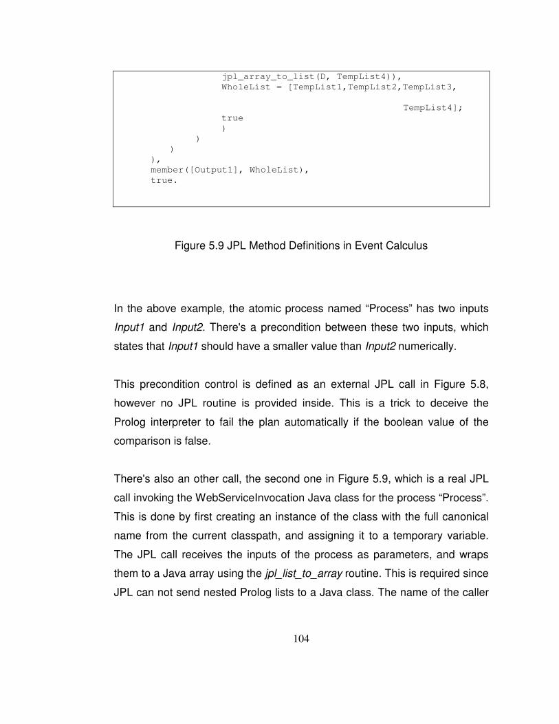
104
jpl_array_to_list(D, TempList4)), WholeList = [TempList1,TempList2,TempList3, TempList4]; true ) ) ) ), member([Output1], WholeList), true.
Figure �5.9 JPL Method Definitions in Event Calculus
In the above example, the atomic process named “Process” has two inputs
Input1 and Input2. There's a precondition between these two inputs, which
states that Input1 should have a smaller value than Input2 numerically.
This precondition control is defined as an external JPL call in Figure 5.8,
however no JPL routine is provided inside. This is a trick to deceive the
Prolog interpreter to fail the plan automatically if the boolean value of the
comparison is false.
There's also an other call, the second one in Figure 5.9, which is a real JPL
call invoking the WebServiceInvocation Java class for the process “Process”.
This is done by first creating an instance of the class with the full canonical
name from the current classpath, and assigning it to a temporary variable.
The JPL call receives the inputs of the process as parameters, and wraps
them to a Java array using the jpl_list_to_array routine. This is required since
JPL can not send nested Prolog lists to a Java class. The name of the caller

105
process, and the Java array created is then wrapped as a list and fed to the
invokeService method of the WebServiceInvocation class.
Additional pieces of information could be passed to the invokeService
method to enable better service discovery in the runtime, however for the
scope of this thesis, simply the process name is used as a distinguisher.
An array of output lists is then received and via certain JPL and Prolog tricks
the array is converted to a list of lists. The service invocation method returns
multiple output lists, since more than one service might be discovered with
the along passed information, and each of these services may return their
own outputs.
Prolog should handle all the outputs for the given services, however a direct
“array of arrays” conversion is not provided in JPL, hence the manual
routine. For the scope of this thesis, a set of 4 distinct services are supported
per each discovery, and unlimited outputs are supported for each process.
In the last step the member operator is used to enumerate the output lists
against the outputs of the process (which are listed in a Prolog list in the
order defined in the OWL-S composition).
A second type of Prolog to Java call is made for SWRL conditions specified
in the If case of If-Then-Else compositions. This is a selected approach since
evaluating an SWRL condition in Prolog takes considerably larger effort than
evaluating the condition in Java. A sample JPL call made for an If evaluation
is provided in Figure 5.10.

106
jpl_ifCondition(IfOperator, Input1, Input2, IfResult) :-
jpl_new('tr.edu.metu.prolog.WebServiceInvocation', [], WSI),
jpl_list_to_array([IfOperator, Input1, Input2], InputArray),
jpl_call(WSI, evaluateIf, [InputArray], OutputArray),
(OutputArray == @(null) -> OutputList = [] ;
jpl_array_to_list(OutputArray, OutputList)),
member(IfResult, OutputList),
IfResult.
Figure �5.10 JPL Call of an If Condition in an If-Then-Else Process
In the above example, there's an if condition which takes Input1 and Input2
literals as inputs, and operates with IfOperator over those inputs. The if
operator is parsed from the SWRL expression in the OWL-S file, and
provided to the Java class for condition evaluation. Sample condition
operators include “less than”, “equal”, “not equal” etc.
5.9.3 Calls from Java to Prolog
Java to Prolog interaction with JPL calls are made from the web application,
to pass the inputs provided by the user to the Prolog engine. The abductive
event calculus planner and the dynamically generated Prolog code for the
composition are both consulted to a Prolog session. Then the Prolog query is
created with the user inputs and fed to JPL to generate all possible plans for
the currently selected composition.
Results of the query are received via a Hashmap in JPL result object
hierarchy. Each entry in the Hashmap denotes a possible plan for the user

107
query. These entries are then parsed with the plan visualizer to be displayed
on the web.
A sample code snippet is provided in Figure 5.11.
Query consultEventCalculus = new Query("consult", new Term[] { new Atom(eventCalculusPlanner.getAbsolutePath()) }); consultEventCalculus.query(); Query consultDynamicProlog = new Query("consult", new Term[] { new Atom(dynamicProlog.getAbsolutePath()) }); consultDynamicProlog.query(); Query query = new Query(prologQuery); results = query.allSolutions();
Figure �5.11 JPL Call to a Composition from Java
In the above sample, firstly the event calculus library is loaded, and then the
dynamically generated Prolog code is loaded to the Prolog interpreter. Lastly
the Prolog query generated with the inputs of the user is sent to the
interpreter, and the results are requested. A sample Prolog query is as
follows:
abdemo([holds_at(pProcessPlanned("UserInput1","UserInput2"),t)], R).
108
In the above example, the inputs “UserInput1” and “UserInput 2” are two
Strings provided by the user of the system from the web interface for
execution.
5.9.4 Input Types
The intermediate step between Prolog generation and execution is the
interactive input request screen. In this screen, the inputs required by the
process are requested from the user. The screen contains the names of the
inputs and hints the processes within the composition that will use the input.
This way it is easier for the user to provide values for fields with non-
descriptive and generic names like “Date” or “Name”.
A second feature is different field handlers for certain inputs. By default, each
input is provided a text-field accepting alphanumeric characters. However,
for known types like Date, Time and Password, date-time pickers and
password fields are also provided. This way, the user does not have to type
in everything manually.
The decision for specific field handlers are given based on two factors, first
one being the type attribute of the field. If the type of a field is Date, an
immediate positive signal is given for a Date field handler. However, not
every field type is known apriori by the application, therefore field names are
also parsed. This way missing field types are also handled, for instance if an
input has the label “Expiration Date”, and its type is “String” in the OWL-S
file, the application will still provide a Date field handler for this input. A
sample user input screen of the web application is shown in Figure 5.12.

109
Figure �5.12 OWL-S Composition Input Screen
5.9.5 Service Discovery at Execution Time
Neither the OWL-S description nor the generated Prolog code includes any
grounding information, thus to plan the composition, discovery for the
services matching the given specifications is necessary. Since service
discovery is beyond the scope of this thesis, this part is simulated with a
service discovery stub.
110
The JPL calls in the generated Prolog code carry the following information
about the services that are to be discovered: the name of the process, the
number and names of the inputs and outputs. Further information like the
type of the inputs and outputs, the preconditions, quality of service
requirements, labels of IOPEs and descriptions of processes can also be
provided to service discovery engine, for a better semantic discovery.
The current service discovery engine responds to discovery queries with a
pre-established set of services suitable for the set of processes that have
been tested for demo purposes.
5.9.6 Plan Selection
After the inputs are at hand, and the necessary services are discovered via
the service discovery engine, the generated Prolog code returns plans for the
given generic service composition. The number of plans returned by the
abductive planner depends on the number of services discovered and the
type of the composition at hand.
For instance, for a “Choice” type of composition, the amount of plans is at
least the number of processes in the Choice construct. Permutations
regarding the available services, types of composition(s) are all handled by
Prolog.
The user is then provided a set of plans, which contain an ordering with the
name of the processes that will be executed. The inputs provided by the user
are also embedded in the plans, for a better understanding of what will
happen if the composition is executed. Since no execution has been
performed yet, the generated plans do not contain any real outputs, rather
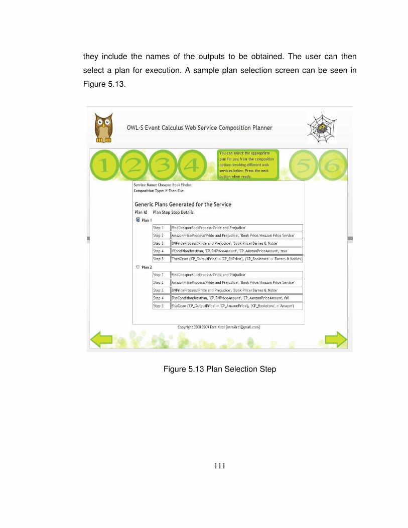
111
they include the names of the outputs to be obtained. The user can then
select a plan for execution. A sample plan selection screen can be seen in
Figure 5.13.
Figure �5.13 Plan Selection Step

112
5.9.7 Execution Mode
In the execution mode, the services in the plan which are selected by the
user in the previous step are executed in the order specified in the plan.
Service execution is beyond the scope of this thesis, therefore the outputs
obtained are simulated outputs, and do not differ based on the given input.
To differentiate world-altering and information-providing services, the
execution mode takes one step for the information-providing services and
two steps for the world-altering services. For the information providing
services, after the plan selection, the actual service is executed and the
outputs of it are shown immediately. For the world-altering services and
composite services containing at least one world-altering service as a child,
in the first step of execution mode, after the plan selection, simulated outputs
are displayed to the user. The user has to proceed one more step to execute
the actual service and see the actual outputs of it for these type of services.
A sample execution step is illustrated in Figure 5.14.

113
Figure �5.14 Plan Execution Step
After the plan execution step, the user selects the plan to be executed, and
the outputs obtained from that plan are listed on a separate screen for
execution confirmation, and a better viewing experience, as in Figure 5.15.

114
Figure �5.15 Execution Output Step
5.10 System Performance
The performance of the system is affected by many factors. The system runs
in a J2EE server, and main reasons for the delays are network overheads,
RDF parsing and Prolog invocation via Java.
5.10.1 Network Delays
Most OWL-S documents include namespace and import declarations to
external resources. The OWL-S parsers need to download the referenced
resources via their provided paths. Even though this necessity seems fair
115
theoretically, in practice it yields to long download delays. Since certain
resources referred by the OWL-S descriptions are either no longer present or
hosted at different locations, even longer delays are encountered with
timeouts.
To provide a better user experience with the download of these resources,
local mechanisms should be used whenever possible. Throughout the
implementation of this thesis, the productive environment for the web
application had several DNS mappings and a local HTTP server to decrease
delays with widely used imports.
As an example, the resource “http://www.w3.org/2000/01/rdf-schema” is
mapped as “rdfs” entity in valid OWL-S documents. Normally, the parser tries
to navigate to the server “www.w3.org” and to the folder “2000/01/rdf-
schema”. Since external Domain Name Servers correctly respond with the IP
“128.30.52.51” to the name server query for “www.w3.org”, the OWL-S
parsers try to connect to this server. To disable this, a DNS record can be
inserted to the hosts file of the operating system. When this record is
created, an external DNS query is not even necessary. In a Linux
environment this can be achieved by inserting “127.0.0.1 www.w3.org” line to
“/etc/hosts” file.
Since parsers now try to connect to the localhost to download the required
file, the file and folder structure should be created properly for a successful
download. Apache2 WWW Server has been used in this case. In the WWW
root of Apache2, the “2000/01” folder hierarchy is created and “rdf-schema”
document is placed exactly as the same folder structure as in www.w3.org.

116
As a final step, an additional trick is necessary in the Java code since the
Java Virtual Machine (JVM) has its own DNS caching mechanism, which
caches an address forever once it has been looked up. This poses a problem
since www.w3.org or any other address could have been cached via JVM
prior to this project. To prevent this JVM DNS caching,
“networkaddress.cache.ttl” Java system property should be set to “0”.
Figure 5.16 illustrates the OWL-S parsing delays for locally hosted vs.
remote resources.
Figure �5.16 Local vs. Remote Resource Usage
Apart from the complex and CPU intensive If-Then-Else compositions, there
are 3 to 5 times performance gains with the usage of locally hosted
resources. More detailed comparison charts are provided in the Appendix C.

117
5.10.2 RDF Parsing
Since OWL-S documents are in RDF format, these documents should be
parsed via the OWL-S APIs to create the business model. The parsing takes
quite less time in contrast with the experienced network delays.
Total time:
10422ms
Total time:
1145ms
Figure �5.17 Distribution of Delays in a Choice Type of Composition
Figure 5.17 depicts the time distribution of tasks in a sample composition for
the first three steps of the application. When local (cached) resources are
used for OWL-S parsing, the total time required for the Prolog generation
decreases dramatically, however the percentage of OWL-S parsing still
increases. This is because the “Image Processing” step also does an amount
of OWL-S parsing to generate a business model for the composition, and
that step also takes less time when resources are local.

118
5.10.3 JPL Calls and Prolog
The system uses SWI Prolog, and Java Interface to Prolog to bind to the
generated Prolog codes. Individual JPL calls are not as expensive as running
Prolog code from an editor visually. The cost of a Prolog call is shown in
Figure 5.18.
Figure �5.18 JPL Delays for a Sample Any-Order Composition
As illustrated above, there are three types of JPL delays: firstly the Prolog file
consultation, secondly invocation and thirdly parsing of JPL results. The most
expensive operation is consulting a Prolog file (888ms in the above
example), however this step needs to be executed only once. A consulted
Prolog file can be used many times with different Prolog queries.
119
CHAPTER 6
CONCLUSION AND FUTURE WORK
6.1 Summary and Conclusions
In this thesis, an approach and its implementation are presented for the
automated composition of semantic web services problem. The applicable
scenario for our approach is that, given a generic web service composition
definition, our system generates plans as compositions including available
services matching the requirements of the generic composition definition.
The inputs needed by the composition are provided by the user, and after the
planning phase the user is able to select a plan from the generated list of
possible plans and execute it with the provided inputs.
A subset of OWL-S ontology is used for generic web service composition
definitions. OWL-S process model has the necessary features for defining
the structure of the composition with its semantic information. The generic
composition definition in OWL-S includes:
• The definitions for the composite services and the atomic services
included in them with their inputs, outputs, preconditions and effects,

120
• The data flow and binding information for the parameters of services,
• The control flow information which characterizes the structure of the
composition and temporal relationship between the included services.
The composition is defined similar to a workflow structure with these
elements. Profile and grounding parts of OWL-S are not needed for our
framework, but profile definition is displayed to the user if it exists. Also it
may be beneficial for the discovery phase, which is not covered in this work.
The generic service compositions are provided to our system via uploading
the actual OWL-S file, or providing the necessary URL. Then our framework
reads in the generic composition definition and displays the graphical
representation of it for a better understanding of the composition. Then the
inputs needed by the composition are taken from the user and the planning
phase begins.
Abductive planning capability of the event calculus, which is a logical
formalism for the description of actions and their effects in dynamic
environments, is used for planning. The generic composition in OWL-S is
converted to the event calculus axioms in Prolog language. Then a goal
situation is given and plans, which constitute the necessary middle steps
between the initial state and the goal state, are generated by the abductive
theorem prover in the event calculus to reach that goal. In the plan
generation phase, the abductive planner communicates with the web service
discovery module and gets the properties of the atomic services matching
the atomic events in the composition whenever such an event is encountered
in the planning process. After the plans are generated, there are two steps
before the execution of the composition. First, the plans including just the

121
names of the discovered services and names of the parameters belonging to
those services are presented to the user. In this step, the user can select the
plan including the actual services which s/he prefers. Second, after the user
selects the preferred plan and presses the Next button, the information-
providing services included in the selected plan are executed and the plan is
again shown to the user for confirmation before executing the whole plan
with the world-altering services.
In some cases, when the information-providing service has an input which is
an output of a world-altering service, the information-providing service is not
executed either. The outputs of it are simulated as if it is a world-altering
service.
The event calculus is used as a middleground for the execution phase as
well as for the planning phase. The only difference is that, in the planning
phase, the abductive theorem prover is connected with the discovery
module; whereas in the execution phase, it is connected with the execution
module. In the planning and execution phases, the preconditions are also
checked, and the service takes place in the plan or is executed only if its
preconditions are satisfied.
Our tool provides the first web service composition platform using abductive
event calculus as the framework for planning. As a proof of concept, it is
shown that, it is possible to represent composite processes defined in OWL-
S in event calculus domain automatically in a lossless manner. Also, it is
shown that the event calculus, which is declarative and has clear semantics,
is a very suitable platform for web service composition problem, because of
the ease in plan generation. Unlike methods using the situation calculus, our
122
tool can differentiate between the information-providing and world-altering
services, and treats them according to their nature without making any
assumptions.
6.2 Future Work
In our framework, the service discovery and execution modules are
simulated. As a future work, these modules can be replaced with the actual
discovery and execution components and integrated to our system. Also,
currently our system does not handle conditional outputs. The event calculus
axioms are generated dynamically just after the OWL-S file is provided to the
system, and these axioms include the definitions of the services including the
inputs and outputs of them. The number of outputs of a service should be
static and match with the event calculus definition of that service for the
planner to work successfully. Another layer can be added as a future work to
handle conditional outputs as well.
Our system takes ready OWL-S files as generic composition definitions.
Another component for creating the OWL-S files dynamically according to
the user’s needs can be integrated to our system as another future work.
This component may gather the user’s needs graphically and generate the
corresponding OWL-S file.
In the screen used for taking the input values from the user in the web
module, which can be seen in Figure 5.12, custom input fields are shown
only for a limited number of types of inputs. Only the fields for the date-time
picker and password are currently handled. The usual textbox is displayed
for all other types of inputs. This can be improved to handle also the types

123
such as credit card, telephone number, bollean values, currency, only-
numeric etc.
In our tool, performance loss is mainly due to the delay in Java-Prolog
interface and to the effort spent to make the plans coming ATP more
representable in a human-readable format. If ATP could be implemented in
Java, in such a way that the plans from it are generated in a more
representable way, such as a graph, the performance would increase vastly
and the effort to develep a program using ATP would be so much easier.
Only the primitive types string and integer are handled in ATP due to the
restrictions of Prolog. A layer can be put in between Java and Prolog in order
to enable passing other complex types to the planner.
Another future work might include handling all types of conditions written in
SWRL to use the full power of it. Our tool handles only numeric values for the
conditions. SWRL has some other built-in structures for strings, boolean
values, date, time, duration, URIs and lists. Extensions can be made for
handling these other structures.

124
REFERENCES
1. Andrews, T., Curbera, F., Dholakia, H., and Goland, Y., Business Process Execution Language for Web Services, Version http://www.ibm.com/developerworks/library/specification/ws-bpel/, 2003.
2. Arkin, A., Business Process Modeling Language, Version 1.0, Business Management Initiative, http://www.bpmi.org/, August 2008.
3. Arkin A., Askary S., Fordin S., Jekeli W., Kawaguchi K., Orchard D.,
Pogliani S., Riemer K., Struble S., Takaci-Nagy P., Trickovic I., and Zimek S., Web Service Choreography Interface (WSCI) 1.0. Published on the World Wide Web by BEA Systems, Intalio, SAP, and Sun Microsystems, 2002.
4. Au, T.C., Kuter, U., and Nau, D., Web Service Composition with Volatile Information, International Semantic Web Conference, 2005.
5. Aydin, O., Automated Web Services Composition with the Event Calculus, M.S. Thesis, METU, 2005.
6. Bachlechner, D., Lausen, H., Siorpaes, K., Fensel, D., Web Service Discovery-A Reality Check, Third Annual European Semantic Web Conference ESWC'06, 2006.
7. Bechhofer, S., Harmelen, F., Hendler, J., Horrocks, I., McGuinness, D.L., Patel-Schneider, P.F., and Stein, L.A., OWL Web Ontology Language Reference, W3C Recommendation 10 February 2004,
125
W3C Technical Reports and Publications, http://www.w3.org/TR/owl-ref/, August 2008.
8. Benatallah, B., Sheng, Q.Z., Ngu, A.H.H., and Dumas, M., Declarative Composition and Peer-to-Peer Provisioning of Dynamic Web Services, Proc. of the 18th Int. Conf. on Data Engineering (ICDE'02), 2002.
9. Berners-Lee, T., Hendler, J., and Lassila, O., The Semantic Web, Scientific American Magazine, 2001.
10. Blum, A., and Furst, M., Fast Planning Through Planning Graph Analysis, Proceedings of the 14th International Joint Conference on Artificial Intelligence - IJCAI95, pp. 1636–1642, 1995.
11. Booth, D., Haas, H., McCabe, F., Newcomer, E., Champion, M., Ferris, C., and Orchard, D., Web Services Architecture, W3C Working Group Note 11 February 2004, W3C Technical Reports and Publications, http://www.w3.org/TR/ws-arch/, August 2008.
12. Casati, F., Ilnicki, S., and Jin, L., Adaptive and Dynamic Service Composition in eFlow, Proceedings of 12th Int. Conference on Advanced Information Systems Engineering(CAiSE), 2000.
13. Christensen, E., Curbera, F., Meredith, G., and Weerawarana, S., Web Services Description Language (WSDL) 1.1, W3C Note 15 March 2001, W3C Technical Reports and Publications, http://www.w3.org/TR/wsdl/, August 2008.
14. Aydin, O., Cicekli, N.K., Cicekli, I., Automated Web Services
Composition with Event Calculus, Proceedings of the 8th International Workshop in \Engineering Societies in the Agents World" (ESAW07), 2007.
126
15. Curbera F., Goland Y., Klein J., Leymann F., Roller D, Thatte S., and Weerawarana S., Business Process Execution Language for Web Service (BPEL4WS) 1.0., Published on the World WideWeb by BEA Corp., IBM Corp. and Microsoft Corp., August 2002.
16. Davulcu, H., Kifer, M., Pokorny, L., Ramakrishnan, C.R., Ramakrishnan, I.V., and Dawson, S., Modelling and Analysis of Interactions in Virtual Enterprises, RIDE, pp. 12-18, 1998.
17. Dustdar, S., and Schreiner, W., A Survey on Web Services Composition, Int. J. Web Grid Serv. 1 (1), pp. 1–30, 2005.
18. Eshghi, K., Abductive Planning with Event Calculus, Proceedings of the 5th International Conference and Symposium on Logic Programming, MIT Press, pp. 562--579, 1988.
19. Fikes, R. E. and Nilsson, N. J., STRIPS: a new approach to the
application of theorem proving to problem solving, Artificial Intelligence, 2(3-4): pages 189-208, 1971.
20. Fujii, K., and Suda, T., Component Service Model with Semantics (CoSMoS): A new Component Model for Dynamic Service Composition, Proceedings of Applications and the Internet Workshops (SAINTW’04), pp. 348-355, 2004.
21. Gardner, T., An Introduction to Web Services, Ariadne Issue 29, http://www.ariadne.ac.uk/issue29/gardner, August 2008
22. Garofalakis, J., Panagis, Y., Sakkopoulos, E., and Tsakalidis, A., Web Service Discovery Mechanisms: Looking for a Needle in a Haystack, International Workshop on Web Engineering, 2004.
23. Ghallab, M., Howe, A., Knoblock, C., McDermott, D., Ram, A., Veloso, M., Weld, D., and Wilkins, D., PDDL: The Panning Domain Definition Language, AIPS-98 Planning Committee, 1998.
127
24. Gudgin, M., Hadley, M., Mendelsohn, N., Moreau, J.J., Nielsen, H.F.,
Karmarkar, A., and Lafon, Y., SOAP Version 1.2 Part 1: Messaging Framework (Second Edition), W3C Recommendation 27 April 2007, W3C Technical Reports and Publications, http://www.w3.org/TR/soap12-part1/, August 2008
25. Haas, H., and Brown, A., Web Services Glossary, W3C Working Group Note 11 February 2004, W3C Technical Reports and Publications, http://www.w3.org/TR/ws-gloss/, August 2008
26. Huang, Y., and Walker, D.W., Extensions to Web Service Techniques for Integrating Jini into a Service-Oriented Architecture for the Grid, ICCS 2003, LNCS2659, pp. 254-263, 2003.
27. Hull, R., Hill, M., and Berardi, D., Semantic Web Services Usage Scenario: e-Service Composition in a Behavior based Framework, http://www.daml.org/services/use-cases/language/, August 2008
28. Karagoz, F., Application of Schema Matching Methods to Semantic Web Service Discovery, M.S. Thesis, Dept. of Computer Engineering, METU, Ankara, 2006.
29. Kautz, H., and Selman, B., Planning as satisfiability, In Proceedings of
the 10th European Conference on Artificial Intelligence, 359–363. Wiley, 1992.
30. Kowalski, R. A., and Sergot, M.J., A Logic-Based Calculus of Events, New Generation Computing, Vol. 4(1), pp. 67-95, 1986.
31. Kuster, U., Stern, M., and Konig-Ries, B., A Classification of Issues and Approaches in automatic Service Composition, 1st Int. Workshop on Engineering Service Compositions (WESC05) at ICSOC, 2005.

128
32. Kuter, U., Sirin, E., Parsia, B., Nau, D., and Hendler, J., Information Gathering During Planning for Web Service Composition, Proc. of ICAPS-P4WGS 2004, 2004.
33. Leymann, F., Web Service Flow Language (WSFL 1.0), IBM Software Group, Retrieved August 2008, from http://www.ibm.com/software/solutions/webservices/pdf/WSFL.pdf, 2001.
34. Martin, D., Burstein, M., Hobbs, J., Lassila, O., McDermott, D.,
McIlraith, S., Narayanan, S., Paolucci, M., Parsia, B., Payne, T., Sirin, E., Srinivasan, N., and Sycara, K., OWL-S: Semantic Markup for Web Services, W3C Member Submission 22 November 2004, Acknowledged Member Submissions to W3C, http://www.w3.org/Submission/OWL-S/, August 2008
35. McCarthy, J., Situations, Actions and Casual Laws, Stanford Artificial Intelligence Project: Memo 2, 1963.
36. McDermott, D., Estimated-Regression Planning for Interactions with Web Services, Sixth International Conference on AI Planning and Scheduling, AAAI Press, 2002.
37. McIlraith, S. A., and Son, T.C., Adapting Golog for Composition of Semantic Web Services, Proceedings of Eighth International Conference on Principles of Knowledge Representation and Reasoning, pp. 482-493, 2002.
38. Miller, R., and Shanahan, M., Some Alternative Formulations of the Event Calculus, Computational Logic: Logic Programming and Beyond, Springer-Verlag, pp. 452-490, 2002.
39. Mueller, Erik T., Commonsense Reasoning, pp. 42-43, 2006.

129
40. Mueller, R., Greiner, U., and Rahm, E., Agentwork: A Workflow System Supporting Rule-Based Workflow Adaptation, Journal of Data and Knowledge Engineering, 2004.
41. Nau, D., Au, T.C., Ilghami, O., Kuter, U., Murdock, W., Wu, D., and Yaman, F., SHOP2: An HTN Planning System, JAIR Volume 20, pp. 379–404, 2003.
42. Oh, S.C., Lee, D., and Kumara, S., A Comparative Illustration of AI Planning-based Web Service Composition, ACM SIGecom Exchanges, 5(5), pp. 1-10, 2006.
43. Peer, J., A PDDL Based Tool for Automatic Web Service Composition, PPSWR’ 04: Proceedings of Second International Workshop on Principles and Practice of Semantic Web Reasoning, pp. 149–163, 2004.
44. Peer, J., Web Service Composition as AI Planning - a Survey, Technical report, Univ. of St. Gallen, March 2005.
45. Pistore, M., Bertoli, P., Barbon, F., Shaparau, D., and Traverso, P., Planning and Monitoring Web Service Composition, Proc. of the 14th Int. Conf. on Automated Planning and Scheduling (ICAPS 2004), 2004.
46. Rao, J., and Su, X., A Survey of Automated Web Service Composition Methods, Proceedings of First International Workshop on Semantic Web Services and Web Process Composition, pp 43-54, 2004.
47. Ratnasamy, S., Francis, P., Handley, M., Karp, R., and Shenker, S., A
Scalable Content-Addressable Network, Proceedings of ACM SIGCOMM`01 Conference, pp. 161–172, 2001.
130
48. Rouached, M., and Godart, C., An Event Based Model for Web Service Coordination, 2nd International Conference on Web Information Systems and Technologies - WEBIST 2006, 2006.
49. Rowstron, A., and Druschel, P., Pastry: Scalable, Decentralized Object Location, and Routing for Large-Scale Peer-to-Peer Systems, Lecture Notes In Computer Science, 2001.
50. Shanahan, M.P., An Abductive Event Calculus Planner, The Journal of Logic Programming, Vol. 44(1-3), pp. 207--240, 2000.
51. Shanahan, M.P., Event Calculus Planning Revisited, Proceedings 4th European Conference on Plannning (ECP 97), Springer-Verlag Lecture Notes in Artificial Intelligence no. 1348, pages 390-402, 1997.
52. Shanahan, M., Representing Continuous Change in the Event Calculus, Proceedings of ECAI'90 Conference, Stockholm, pp. 598--603, 1990.
53. Shanahan, M. P., The Event Calculus Explained, Artificial Intelligence Today, Springer-Verlag Lecture Notes in Artificial Intelligence no. 1600, Springer-Verlag, pp. 409--430, 1999.
54. Sirin, E., Combining Description Logic Reasoning with AI Planning for Composition of Web Services, PhD Thesis, Faculty of the Graduate School of the University of Maryland, , 2006.
55. Sirin, E., Parsia, B., Wu, D., Hendler, J., and Nau, D., HTN planning for web Service Composition Using SHOP2, Journal of Web Semantics, pp. 377–396, 2004.
56. Srinivasan, N., Paolucci, M., and Sycara, K., An Efficient Algorithm for OWL-S Based Semantic Search in UDDI, Lecture Notes in Computer Science, 2005.

131
57. Stoica, I., Morris, R., Karger, D., Kaashoek, F., and Balakrishnan, H., Chord: A Scalable Peer-to-Peer Lookup Service for Internet Applications, Proceedings of ACM SIGCOMM’01 Conference, pp. 149–160, 2001.
58. Su, X., and Rao, J., A Survey of Automated Web Service Composition
Methods, In Proceedings of First International Workshop on Semantic Web Services and Web Process Composition, SWSWPC 2004, pp. 43--54, 2004.
59. Thatte, S., XLANG: Web Services for Business Process Design, Microsoft Corporation, Retrieved August 2008, From http://www.gotdotnet.com/team/xml wsspecs/xlang-c/default.htm, 2001.
60. Verma, K., Sheth, A., Miller, J., and Aggarwal, R., Semantic Web Services Usage Scenario: Dynamic QoS based Supply Chain, Retrieved August 2008, From http://www.daml.org/services/use-cases/architecture/.
61. Wilk, J., Russo, A., and Cunningham, M.J., Dynamic Workflow Pulling the Strings, Distinguished Project (MEng), Department of Computing, Imperial Collage London, 2004.
62. Zhang, J.F., and Kowalczyk, R., Agent-based Dis-graph Planning Algorithm for Web Service Composition, International Conference on Computational Inteligence for Modelling Control and Automation and International Conference on Intelligent Agents Web Technologies and International Commerce (CIMCA'06), pp. 258, 2006.
63. Carnegie Mellon University, OWL-S API, Retrieved August 2008, From http://projects.semwebcentral.org/projects/owl-s-api/.

132
64. The DARPA Agent Markup Language Homepage, Bravo Air Profile Example for OWL-S 1.1, Retrieved August 2008, From http://www.daml.org/services/owl-s/1.1/BravoAirProfile.owl.
65. The DARPA Agent Markup Language Homepage, Bravo Air Process Example for OWL-S 1.1, Retrieved August 2008, From http://www.daml.org/services/owl-s/1.1/BravoAirProcess.owl.
66. eCl@ss, The International Standard for the Classification of Products and Services, Retrieved August 2008, From http://www.eclass-online.com/.
67. D. Tidwell, Web Services—The Web's Next Revolution, IBM tutorial,
2000.
68. JPL - Java Interface to Prolog, Retrieved August 2008, From
http://www.swi-prolog.org/packages/jpl/java_api/index.html.
69. JUNG - Java Universal Network/Graph Framework, Retrieved August 2008, From http://jung.sourceforge.net/.
70. Maryland Information and Network Dynamics Lab, Semantic Web Agents Project (MindSwap) OWL-S API, Retrieved August 2008, From http://www.mindswap.org/2004/owl-s/api/.
71. North American Industry Classification System, NAICS, Retrieved August 2008, From http://www.census.gov/epcd/www/naics.html.
72. OASIS, Organization for the Advancement of Structured Information Standards, Retrieved August 2008, From http://www.oasis-open.org/.

133
73. The DARPA Agent Markup Language Homepage, Process Ontology for OWL-S 1.1, Retrieved August 2008, From http://www.daml.org/services/owl-s/1.1/Process.owl.
74. UDDI, Universal Description, Discovery and Integration, The UDDI Technical White Paper, Retrieved August 2008, From http://www.uddi.org/pubs/Iru_UDDI_Technical_White_Paper.pdf, September 2000.
75. Wikipedia, Web Ontology Language, Retrieved August 2008, From http://en.wikipedia.org/wiki/Web_Ontology_Language.
76. myGrid Team, WonderWeb OWL Ontology Validator, Retrieved August 2008, From http://www.mygrid.org.uk/OWL/Validator.

134
APPENDIX A
SEQUENCE EXAMPLE
A composition example with Sequence control construct in OWL-S, and its
translation to the Event Calculus in Prolog are provided below respectively.
<?xml version="1.0" encoding="windows-1254"?> <!DOCTYPE uridef[ <!ENTITY rdf "http://www.w3.org/1999/02/22-rdf-syntax-ns"> <!ENTITY rdfs "http://www.w3.org/2000/01/rdf-schema"> <!ENTITY owl "http://www.w3.org/2002/07/owl"> <!ENTITY xsd "http://www.w3.org/2001/XMLSchema"> <!ENTITY service "http://www.daml.org/services/owl-s/1.1/Service.owl"> <!ENTITY profile "http://www.daml.org/services/owl-s/1.1/Profile.owl"> <!ENTITY process "http://www.daml.org/services/owl-s/1.1/Process.owl"> <!ENTITY grounding "http://www.daml.org/services/owl-s/1.1/Grounding.owl"> <!ENTITY expr "http://www.daml.org/services/owl-s/1.1/generic/Expression.owl"> <!ENTITY swrl "http://www.w3.org/2003/11/swrl"> <!ENTITY swrlb "http://www.w3.org/2003/11/swrlb"> <!ENTITY list "http://www.daml.org/services/owl-s/1.1/generic/ObjectList.owl"> <!ENTITY concepts "http://www.daml.org/services/owl-s/1.1/Concepts.owl"> <!ENTITY this "http://localhost:801/owl-s/Sequence.owl"> ]> <rdf:RDF xmlns:rdf="&rdf;#" xmlns:rdfs="&rdfs;#" xmlns:owl="&owl;#" xmlns:xsd="&xsd;#" xmlns:service="&service;#" xmlns:profile="&profile;#" xmlns:process="&process;#" xmlns:grounding="&grounding;#" xmlns:expr="&expr;#"
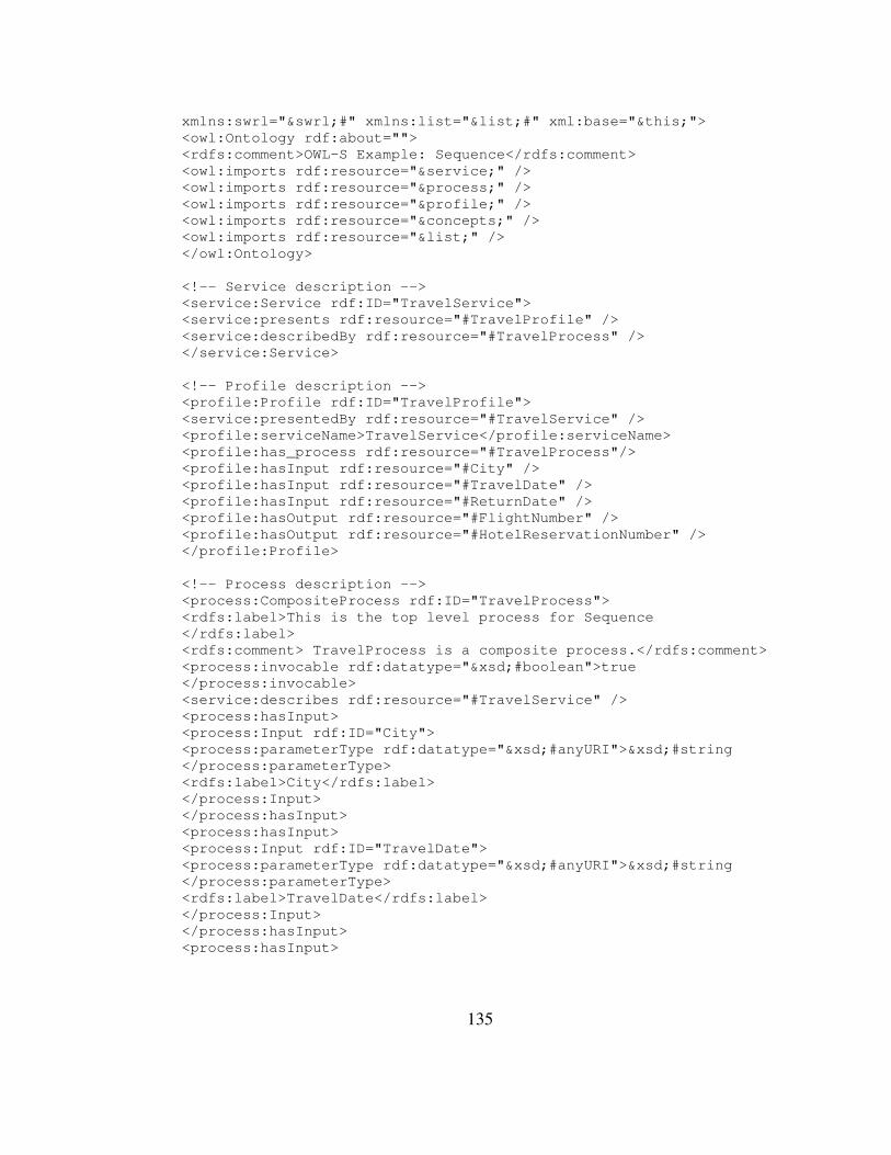
135
xmlns:swrl="&swrl;#" xmlns:list="&list;#" xml:base="&this;"> <owl:Ontology rdf:about=""> <rdfs:comment>OWL-S Example: Sequence</rdfs:comment> <owl:imports rdf:resource="&service;" /> <owl:imports rdf:resource="&process;" /> <owl:imports rdf:resource="&profile;" /> <owl:imports rdf:resource="&concepts;" /> <owl:imports rdf:resource="&list;" /> </owl:Ontology> <!-- Service description --> <service:Service rdf:ID="TravelService"> <service:presents rdf:resource="#TravelProfile" /> <service:describedBy rdf:resource="#TravelProcess" /> </service:Service> <!-- Profile description --> <profile:Profile rdf:ID="TravelProfile"> <service:presentedBy rdf:resource="#TravelService" /> <profile:serviceName>TravelService</profile:serviceName> <profile:has_process rdf:resource="#TravelProcess"/> <profile:hasInput rdf:resource="#City" /> <profile:hasInput rdf:resource="#TravelDate" /> <profile:hasInput rdf:resource="#ReturnDate" /> <profile:hasOutput rdf:resource="#FlightNumber" /> <profile:hasOutput rdf:resource="#HotelReservationNumber" /> </profile:Profile> <!-- Process description --> <process:CompositeProcess rdf:ID="TravelProcess"> <rdfs:label>This is the top level process for Sequence </rdfs:label> <rdfs:comment> TravelProcess is a composite process.</rdfs:comment> <process:invocable rdf:datatype="&xsd;#boolean">true </process:invocable> <service:describes rdf:resource="#TravelService" /> <process:hasInput> <process:Input rdf:ID="City"> <process:parameterType rdf:datatype="&xsd;#anyURI">&xsd;#string </process:parameterType> <rdfs:label>City</rdfs:label> </process:Input> </process:hasInput> <process:hasInput> <process:Input rdf:ID="TravelDate"> <process:parameterType rdf:datatype="&xsd;#anyURI">&xsd;#string </process:parameterType> <rdfs:label>TravelDate</rdfs:label> </process:Input> </process:hasInput> <process:hasInput>

136
<process:Input rdf:ID="ReturnDate"> <process:parameterType rdf:datatype="&xsd;#anyURI">&xsd;#string </process:parameterType> <rdfs:label>ReturnDate</rdfs:label> </process:Input> </process:hasInput> <process:hasOutput> <process:Output rdf:ID="FlightNumber"> <process:parameterType rdf:datatype="&xsd;#anyURI">&xsd;#string </process:parameterType> <rdfs:label>FlightNumber</rdfs:label> </process:Output> </process:hasOutput> <process:hasOutput> <process:Output rdf:ID="HotelReservationNumber"> <process:parameterType rdf:datatype="&xsd;#anyURI">&xsd;#string </process:parameterType> <rdfs:label>HotelReservationNumber </rdfs:label> </process:Output> </process:hasOutput> <process:hasResult> <process:Result> <process:withOutput> <process:OutputBinding> <process:toParam rdf:resource="#FlightNumber" /> <process:valueSource> <process:ValueOf> <process:fromProcess rdf:resource="#PerformFindFlight" /> <process:theVar rdf:resource="#FindFlight_FlightNumber" /> </process:ValueOf> </process:valueSource> </process:OutputBinding> </process:withOutput> </process:Result> </process:hasResult> <process:hasResult> <process:Result> <process:withOutput> <process:OutputBinding> <process:toParam rdf:resource="#HotelReservationNumber" /> <process:valueSource> <process:ValueOf> <process:fromProcess rdf:resource="#PerformFindHotel" /> <process:theVar rdf:resource="#FindHotel_HotelReservationNumber" /> </process:ValueOf> </process:valueSource> </process:OutputBinding> </process:withOutput> </process:Result> </process:hasResult>

137
<process:composedOf> <process:Sequence> <process:components> <process:ControlConstructList> <list:first> <process:Perform rdf:ID="PerformFindFlight"> <process:process> <process:AtomicProcess rdf:ID="FindFlight"> <rdfs:label>FindFlight</rdfs:label> <rdfs:comment>Finds an available flight</rdfs:comment> <process:hasInput> <process:Input rdf:ID="FindFlight_City"> <process:parameterType rdf:datatype="&xsd;#anyURI">&xsd;#string </process:parameterType> </process:Input> </process:hasInput> <process:hasInput> <process:Input rdf:ID="FindFlight_TravelDate"> <process:parameterType rdf:datatype="&xsd;#anyURI">&xsd;#string </process:parameterType> </process:Input> </process:hasInput> <process:hasInput> <process:Input rdf:ID="FindFlight_ReturnDate"> <process:parameterType rdf:datatype="&xsd;#anyURI">&xsd;#string </process:parameterType> </process:Input> </process:hasInput> <process:hasOutput> <process:Output rdf:ID="FindFlight_FlightNumber"> <process:parameterType rdf:datatype="&xsd;#anyURI">&xsd;#string </process:parameterType> </process:Output> </process:hasOutput> </process:AtomicProcess> </process:process> <process:hasDataFrom> <process:InputBinding> <process:toParam rdf:resource="#FindFlight_City" /> <process:valueSource> <process:ValueOf> <process:fromProcess rdf:resource="&process;#TheParentPerform" /> <process:theVar rdf:resource="#City" /> </process:ValueOf> </process:valueSource> </process:InputBinding> </process:hasDataFrom> <process:hasDataFrom> <process:InputBinding> <process:toParam rdf:resource="#FindFlight_TravelDate" /> <process:valueSource>

138
<process:ValueOf> <process:fromProcess rdf:resource="&process;#TheParentPerform" /> <process:theVar rdf:resource="#TravelDate" /> </process:ValueOf> </process:valueSource> </process:InputBinding> </process:hasDataFrom> <process:hasDataFrom> <process:InputBinding> <process:toParam rdf:resource="#FindFlight_ReturnDate" /> <process:valueSource> <process:ValueOf> <process:fromProcess rdf:resource="&process;#TheParentPerform" /> <process:theVar rdf:resource="#ReturnDate" /> </process:ValueOf> </process:valueSource> </process:InputBinding> </process:hasDataFrom> </process:Perform> </list:first> <list:rest> <process:ControlConstructList> <list:first> <process:Perform rdf:ID="PerformFindHotel"> <process:process> <process:AtomicProcess rdf:ID="FindHotel"> <rdfs:label>FindHotel</rdfs:label> <rdfs:comment>Finds an available hotel</rdfs:comment> <process:hasInput> <process:Input rdf:ID="FindHotel_City"> <process:parameterType rdf:datatype="&xsd;#anyURI">&xsd;#string </process:parameterType> </process:Input> </process:hasInput> <process:hasInput> <process:Input rdf:ID="FindHotel_TravelDate"> <process:parameterType rdf:datatype="&xsd;#anyURI">&xsd;#string </process:parameterType> </process:Input> </process:hasInput> <process:hasInput> <process:Input rdf:ID="FindHotel_ReturnDate"> <process:parameterType rdf:datatype="&xsd;#anyURI">&xsd;#string </process:parameterType> </process:Input> </process:hasInput> <process:hasOutput> <process:Output rdf:ID="FindHotel_HotelReservationNumber"> <process:parameterType rdf:datatype="&xsd;#anyURI">&xsd;#string </process:parameterType> </process:Output>
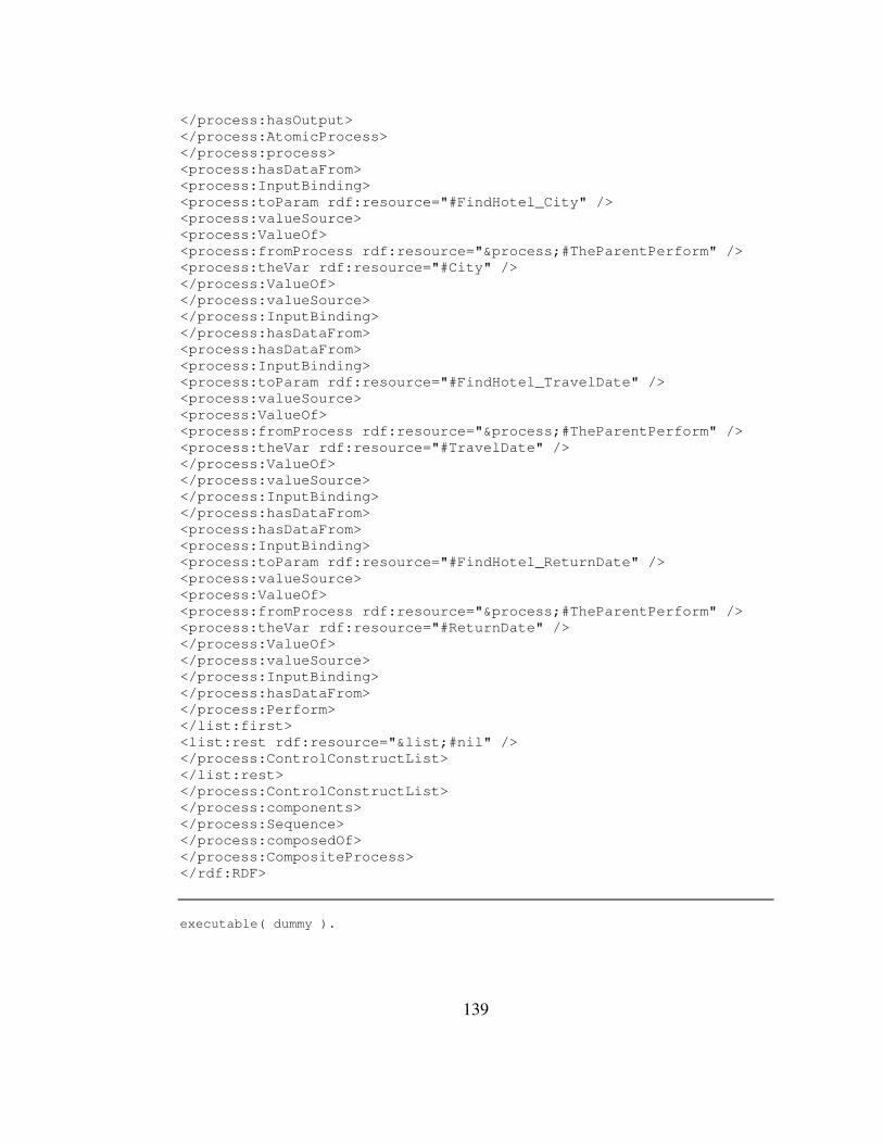
139
</process:hasOutput> </process:AtomicProcess> </process:process> <process:hasDataFrom> <process:InputBinding> <process:toParam rdf:resource="#FindHotel_City" /> <process:valueSource> <process:ValueOf> <process:fromProcess rdf:resource="&process;#TheParentPerform" /> <process:theVar rdf:resource="#City" /> </process:ValueOf> </process:valueSource> </process:InputBinding> </process:hasDataFrom> <process:hasDataFrom> <process:InputBinding> <process:toParam rdf:resource="#FindHotel_TravelDate" /> <process:valueSource> <process:ValueOf> <process:fromProcess rdf:resource="&process;#TheParentPerform" /> <process:theVar rdf:resource="#TravelDate" /> </process:ValueOf> </process:valueSource> </process:InputBinding> </process:hasDataFrom> <process:hasDataFrom> <process:InputBinding> <process:toParam rdf:resource="#FindHotel_ReturnDate" /> <process:valueSource> <process:ValueOf> <process:fromProcess rdf:resource="&process;#TheParentPerform" /> <process:theVar rdf:resource="#ReturnDate" /> </process:ValueOf> </process:valueSource> </process:InputBinding> </process:hasDataFrom> </process:Perform> </list:first> <list:rest rdf:resource="&list;#nil" /> </process:ControlConstructList> </list:rest> </process:ControlConstructList> </process:components> </process:Sequence> </process:composedOf> </process:CompositeProcess> </rdf:RDF>
executable( dummy ).

140
abducible(dummy). :- use_module(library(jpl)). %abdemo([holds_at(pTravelProcessPlanned(ReturnDate, TravelDate, City), t)], R). axiom(initiates(pTravelProcess(ReturnDate, TravelDate, City),pTravelProcessPlanned(ReturnDate, TravelDate, City), T), [ ] ). axiom(happens(pTravelProcess(ReturnDate, TravelDate, City), T1, TN), [ happens(pFindFlight(ReturnDate, TravelDate, City, FlightNumber), T2, T3), happens(pFindHotel(ReturnDate, TravelDate, City, HotelReservationNumber), T4, T5), before(T1, T2), before(T3, T4), before(T5, TN) ] ). %Atomic Process Prolog:FindFlight %Atomic Process Prolog:FindHotel %%% INDIVIDUAL AXIOMS %%% axiom(happens(pFindFlight(ReturnDate, TravelDate, City, FlightNumber), T1, TN), [ jpl_pFindFlight(ReturnDate, TravelDate, City, FlightNumber) ]). axiom(happens(pFindHotel(ReturnDate, TravelDate, City, HotelReservationNumber), T1, TN), [ jpl_pFindHotel(ReturnDate, TravelDate, City, HotelReservationNumber) ]). %%% EX_WEBSERVICE DECLARATIONS %%% ex_WebService(jpl_pFindFlight(_,_,_,_)). ex_WebService(jpl_pFindHotel(_,_,_,_)). %%% JPL METHOD DEFINITIONS %%% jpl_pFindFlight(ReturnDate, TravelDate, City, FlightNumber) :- jpl_new('tr.edu.metu.prolog.WebServiceInvocation', [], WSI), jpl_list_to_array([ReturnDate, TravelDate, City], InputArray), jpl_call(WSI, invokeService, ['pFindFlight', InputArray], OutputArray), (OutputArray == @(null) -> OutputList = [] ; jpl_array_to_list(OutputArray, OutputList)), length(OutputList,Length), ( Length==1 -> [A] = OutputList, (A == @(null) -> TempList1 = [] ; jpl_array_to_list(A, TempList1)), WholeList = [TempList1]; ( Length==2 -> [A,B] = OutputList, (A == @(null) -> TempList1 = [] ;

141
jpl_array_to_list(A, TempList1)), (B == @(null) -> TempList2 = [] ; jpl_array_to_list(B, TempList2)), WholeList = [TempList1, TempList2]; ( Length==3 -> [A,B,C] = OutputList, (A == @(null) -> TempList1 = [] ; jpl_array_to_list(A, TempList1)), (B == @(null) -> TempList2 = [] ; jpl_array_to_list(B, TempList2)), (C == @(null) -> TempList3 = [] ; jpl_array_to_list(C, TempList3)), WholeList = [TempList1, TempList2, TempList3]; ( Length==4 -> [A,B,C,D] = OutputList, (A == @(null) -> TempList1 = [] ; jpl_array_to_list(A, TempList1)), (B == @(null) -> TempList2 = [] ; jpl_array_to_list(B, TempList2)), (C == @(null) -> TempList3 = [] ; jpl_array_to_list(C, TempList3)), (D == @(null) -> TempList4 = [] ; jpl_array_to_list(D, TempList4)), WholeList = [TempList1, TempList2, TempList3, TempList4]; true ) ) ) ), member([FlightNumber], WholeList), true. jpl_pFindHotel(ReturnDate, TravelDate, City, HotelReservationNumber) :- jpl_new('tr.edu.metu.prolog.WebServiceInvocation', [], WSI), jpl_list_to_array([ReturnDate, TravelDate, City], InputArray), jpl_call(WSI, invokeService, ['pFindHotel', InputArray], OutputArray), (OutputArray == @(null) -> OutputList = [] ; jpl_array_to_list(OutputArray, OutputList)), length(OutputList,Length), ( Length==1 -> [A] = OutputList, (A == @(null) -> TempList1 = [] ; jpl_array_to_list(A, TempList1)), WholeList = [TempList1]; ( Length==2 -> [A,B] = OutputList, (A == @(null) -> TempList1 = [] ; jpl_array_to_list(A, TempList1)), (B == @(null) -> TempList2 = [] ; jpl_array_to_list(B, TempList2)), WholeList = [TempList1, TempList2]; ( Length==3 ->

142
[A,B,C] = OutputList, (A == @(null) -> TempList1 = [] ; jpl_array_to_list(A, TempList1)), (B == @(null) -> TempList2 = [] ; jpl_array_to_list(B, TempList2)), (C == @(null) -> TempList3 = [] ; jpl_array_to_list(C, TempList3)), WholeList = [TempList1, TempList2, TempList3]; ( Length==4 -> [A,B,C,D] = OutputList, (A == @(null) -> TempList1 = [] ; jpl_array_to_list(A, TempList1)), (B == @(null) -> TempList2 = [] ; jpl_array_to_list(B, TempList2)), (C == @(null) -> TempList3 = [] ; jpl_array_to_list(C, TempList3)), (D == @(null) -> TempList4 = [] ; jpl_array_to_list(D, TempList4)), WholeList = [TempList1, TempList2, TempList3, TempList4]; true ) ) ) ), member([HotelReservationNumber], WholeList), true.

143
APPENDIX B
EXAMPLE IN TRAVEL DOMAIN
A generic composition in travel domain including various control constructs is
provided below. First the OWL-S file, then its translation to the Event
Calculus domain in Prolog will be provided.
<?xml version="1.0" encoding="windows-1254"?> <!DOCTYPE uridef[ <!ENTITY rdf "http://www.w3.org/1999/02/22-rdf-syntax-ns"> <!ENTITY rdfs "http://www.w3.org/2000/01/rdf-schema"> <!ENTITY owl "http://www.w3.org/2002/07/owl"> <!ENTITY xsd "http://www.w3.org/2001/XMLSchema"> <!ENTITY service "http://www.daml.org/services/owl-s/1.1/Service.owl"> <!ENTITY profile "http://www.daml.org/services/owl-s/1.1/Profile.owl"> <!ENTITY process "http://www.daml.org/services/owl-s/1.1/Process.owl"> <!ENTITY grounding "http://www.daml.org/services/owl-s/1.1/Grounding.owl"> <!ENTITY expr "http://www.daml.org/services/owl-s/1.1/generic/Expression.owl"> <!ENTITY swrl "http://www.w3.org/2003/11/swrl"> <!ENTITY swrlb "http://www.w3.org/2003/11/swrlb"> <!ENTITY list "http://www.daml.org/services/owl-s/1.1/generic/ObjectList.owl"> <!ENTITY concepts "http://www.daml.org/services/owl-s/1.1/Concepts.owl"> <!ENTITY this "http://localhost:801/owl-s/Sequence.owl"> ]> <rdf:RDF xmlns:rdf="&rdf;#" xmlns:rdfs="&rdfs;#" xmlns:owl="&owl;#" xmlns:xsd="&xsd;#" xmlns:service="&service;#" xmlns:profile="&profile;#" xmlns:process="&process;#" xmlns:grounding="&grounding;#" xmlns:expr="&expr;#" xmlns:swrl="&swrl;#" xmlns:list="&list;#" xml:base="&this;"> <owl:Ontology rdf:about=""> <rdfs:comment>OWL-S Example: Sequence</rdfs:comment> <owl:imports rdf:resource="&service;" /> <owl:imports rdf:resource="&process;" /> <owl:imports rdf:resource="&profile;" /> <owl:imports rdf:resource="&concepts;" /> <owl:imports rdf:resource="&list;" />

144
</owl:Ontology> <!-- Service description --> <service:Service rdf:ID="TravelService"> <service:presents rdf:resource="#TravelProfile" /> <service:describedBy rdf:resource="#TravelProcess" /> </service:Service> <!-- Profile description --> <profile:Profile rdf:ID="TravelProfile"> <service:presentedBy rdf:resource="#TravelService" /> <profile:serviceName>TravelService</profile:serviceName> <profile:has_process rdf:resource="#TravelProcess" /> <profile:hasInput rdf:resource="#City" /> <profile:hasInput rdf:resource="#TravelDate" /> <profile:hasInput rdf:resource="#ReturnDate" /> <profile:hasInput rdf:resource="#ShouldRentACar" /> <profile:hasOutput rdf:resource="#RemoteTransportationReservationNumber" /> <profile:hasOutput rdf:resource="#HotelReservationNumber" /> <profile:hasOutput rdf:resource="#TransportationReservationNumber" /> </profile:Profile> <!-- Process description --> <process:CompositeProcess rdf:ID="TravelProcess"> <rdfs:label> This is the top level process for Sequence</rdfs:label> <rdfs:comment> TravelProcess is a composite process.</rdfs:comment> <process:invocable rdf:datatype="&xsd;#boolean"> true </process:invocable> <service:describes rdf:resource="#TravelService" /> <process:hasInput> <process:Input rdf:ID="City"> <process:parameterType rdf:datatype="&xsd;#anyURI">&xsd;#string </process:parameterType> <rdfs:label>City</rdfs:label> </process:Input> </process:hasInput> <process:hasInput> <process:Input rdf:ID="TravelDate"> <process:parameterType rdf:datatype="&xsd;#anyURI">&xsd;#string </process:parameterType> <rdfs:label>TravelDate</rdfs:label> </process:Input> </process:hasInput> <process:hasInput> <process:Input rdf:ID="ReturnDate"> <process:parameterType rdf:datatype="&xsd;#anyURI">&xsd;#string </process:parameterType> <rdfs:label>ReturnDate</rdfs:label> </process:Input> </process:hasInput> <process:hasInput> <process:Input rdf:ID="ShouldRentACar"> <process:parameterType rdf:datatype="&xsd;#anyURI">&xsd;#boolean </process:parameterType> <rdfs:label>ShouldRentACar</rdfs:label> </process:Input> </process:hasInput>
145
<process:hasOutput> <process:Output rdf:ID="RemoteTransportationReservationNumber"> <process:parameterType rdf:datatype="&xsd;#anyURI">&xsd;#string </process:parameterType> <rdfs:label>RemoteTransportationReservationNumber </rdfs:label> </process:Output> </process:hasOutput> <process:hasOutput> <process:Output rdf:ID="HotelReservationNumber"> <process:parameterType rdf:datatype="&xsd;#anyURI">&xsd;#string </process:parameterType> <rdfs:label>HotelReservationNumber </rdfs:label> </process:Output> </process:hasOutput> <process:hasOutput> <process:Output rdf:ID="TransportationReservationNumber"> <process:parameterType rdf:datatype="&xsd;#anyURI">&xsd;#string </process:parameterType> <rdfs:label>TransportationReservationNumber </rdfs:label> </process:Output> </process:hasOutput> <process:hasResult> <process:Result> <process:withOutput> <process:OutputBinding> <process:toParam rdf:resource="#RemoteTransportationReservationNumber" /> <process:valueSource> <process:ValueOf> <process:fromProcess rdf:resource="#PerformFindRemoteTransportation" /> <process:theVar rdf:resource="#FindRemoteTransportation_RemoteTransportationReservationNumber" /> </process:ValueOf> </process:valueSource> </process:OutputBinding> </process:withOutput> </process:Result> </process:hasResult> <process:hasResult> <process:Result> <process:withOutput> <process:OutputBinding> <process:toParam rdf:resource="#HotelReservationNumber" /> <process:valueSource> <process:ValueOf> <process:fromProcess rdf:resource="#PerformFindHotel" /> <process:theVar rdf:resource="#FindHotel_HotelReservationNumber" /> </process:ValueOf> </process:valueSource> </process:OutputBinding> </process:withOutput> </process:Result> </process:hasResult> <process:hasResult>

146
<process:Result> <process:withOutput> <process:OutputBinding> <process:toParam rdf:resource="#TransportationReservationNumber" /> <process:valueSource> <process:ValueOf> <process:fromProcess rdf:resource="#PerformFindLocalTransportation" /> <process:theVar rdf:resource="#FindLocalTransportation_TransportationReservationNumber" /> </process:ValueOf> </process:valueSource> </process:OutputBinding> </process:withOutput> </process:Result> </process:hasResult> <process:composedOf> <process:Sequence> <process:components> <process:ControlConstructList> <list:first> <process:Perform rdf:ID="PerformFindRemoteTransportation"> <process:process> <process:CompositeProcess rdf:ID="FindRemoteTransportation"> <rdfs:label> FindRemoteTransportation</rdfs:label> <rdfs:comment> FindRemoteTransportation</rdfs:comment> <process:hasInput> <process:Input rdf:ID="FindRemoteTransportation_City"> <process:parameterType rdf:datatype="&xsd;#anyURI">&xsd;#string </process:parameterType> </process:Input> </process:hasInput> <process:hasInput> <process:Input rdf:ID="FindRemoteTransportation_TravelDate"> <process:parameterType rdf:datatype="&xsd;#anyURI">&xsd;#string </process:parameterType> </process:Input> </process:hasInput> <process:hasInput> <process:Input rdf:ID="FindRemoteTransportation_ReturnDate"> <process:parameterType rdf:datatype="&xsd;#anyURI">&xsd;#string </process:parameterType> </process:Input> </process:hasInput> <process:hasOutput> <process:Output rdf:ID="FindRemoteTransportation_RemoteTransportationReservationNumber"> <process:parameterType rdf:datatype="&xsd;#anyURI">&xsd;#string </process:parameterType> </process:Output> </process:hasOutput> <process:composedOf> <process:Choice> <process:components> <process:ControlConstructBag> <list:first> <process:Perform rdf:ID="PerformFindFlight"> <process:process>

147
<process:AtomicProcess rdf:ID="FindFlight"> <rdfs:label>FindFlight</rdfs:label> <rdfs:comment>FindFlight</rdfs:comment> <process:hasInput> <process:Input rdf:ID="FindFlight_City"> <process:parameterType rdf:datatype="&xsd;#anyURI">&xsd;#string </process:parameterType> </process:Input> </process:hasInput> <process:hasInput> <process:Input rdf:ID="FindFlight_TravelDate"> <process:parameterType rdf:datatype="&xsd;#anyURI">&xsd;#string </process:parameterType> </process:Input> </process:hasInput> <process:hasInput> <process:Input rdf:ID="FindFlight_ReturnDate"> <process:parameterType rdf:datatype="&xsd;#anyURI">&xsd;#string </process:parameterType> </process:Input> </process:hasInput> <process:hasOutput> <process:Output rdf:ID="FindFlight_RemoteTransportationReservationNumber"> <process:parameterType rdf:datatype="&xsd;#anyURI">&xsd;#string </process:parameterType> </process:Output> </process:hasOutput> </process:AtomicProcess> </process:process> <process:hasDataFrom> <process:InputBinding> <process:toParam rdf:resource="#FindFlight_City" /> <process:valueSource> <process:ValueOf> <process:fromProcess rdf:resource="&process;#TheParentPerform" /> <process:theVar rdf:resource="#City" /> </process:ValueOf> </process:valueSource> </process:InputBinding> </process:hasDataFrom> <process:hasDataFrom> <process:InputBinding> <process:toParam rdf:resource="#FindFlight_TravelDate" /> <process:valueSource> <process:ValueOf> <process:fromProcess rdf:resource="&process;#TheParentPerform" /> <process:theVar rdf:resource="#TravelDate" /> </process:ValueOf> </process:valueSource> </process:InputBinding>
148
</process:hasDataFrom> <process:hasDataFrom> <process:InputBinding> <process:toParam rdf:resource="#FindFlight_ReturnDate" /> <process:valueSource> <process:ValueOf> <process:fromProcess rdf:resource="&process;#TheParentPerform" /> <process:theVar rdf:resource="#ReturnDate" /> </process:ValueOf> </process:valueSource> </process:InputBinding> </process:hasDataFrom> <process:hasDataFrom> <process:InputBinding> <process:toParam rdf:resource="#FindFlight_RemoteTransportationReservationNumber" /> <process:valueSource> <process:ValueOf> <process:fromProcess rdf:resource="&process;#TheParentPerform" /> <process:theVar rdf:resource="#RemoteTransportationReservationNumber" /> </process:ValueOf> </process:valueSource> </process:InputBinding> </process:hasDataFrom> </process:Perform> </list:first> <list:rest> <process:ControlConstructBag> <list:first> <process:Perform rdf:ID="PerformFindBus"> <process:process> <process:AtomicProcess rdf:ID="FindBus"> <rdfs:label> FindBus</rdfs:label> <rdfs:comment> Bike</rdfs:comment> <process:hasInput> <process:Input rdf:ID="FindBus_City"> <process:parameterType rdf:datatype="&xsd;#anyURI">&xsd;#string </process:parameterType> </process:Input> </process:hasInput> <process:hasInput> <process:Input rdf:ID="FindBus_TravelDate"> <process:parameterType rdf:datatype="&xsd;#anyURI">&xsd;#string </process:parameterType> </process:Input> </process:hasInput> <process:hasInput> <process:Input rdf:ID="FindBus_ReturnDate"> <process:parameterType rdf:datatype="&xsd;#anyURI">&xsd;#string </process:parameterType> </process:Input>

149
</process:hasInput> <process:hasOutput> <process:Output rdf:ID="FindBus_RemoteTransportationReservationNumber"> <process:parameterType rdf:datatype="&xsd;#anyURI">&xsd;#string </process:parameterType> </process:Output> </process:hasOutput> </process:AtomicProcess> </process:process> <process:hasDataFrom> <process:InputBinding> <process:toParam rdf:resource="#FindBus_City" /> <process:valueSource> <process:ValueOf> <process:fromProcess rdf:resource="&process;#TheParentPerform" /> <process:theVar rdf:resource="#City" /> </process:ValueOf> </process:valueSource> </process:InputBinding> </process:hasDataFrom> <process:hasDataFrom> <process:InputBinding> <process:toParam rdf:resource="#FindBus_TravelDate" /> <process:valueSource> <process:ValueOf> <process:fromProcess rdf:resource="&process;#TheParentPerform" /> <process:theVar rdf:resource="#TravelDate" /> </process:ValueOf> </process:valueSource> </process:InputBinding> </process:hasDataFrom> <process:hasDataFrom> <process:InputBinding> <process:toParam rdf:resource="#FindBus_ReturnDate" /> <process:valueSource> <process:ValueOf> <process:fromProcess rdf:resource="&process;#TheParentPerform" /> <process:theVar rdf:resource="#ReturnDate" /> </process:ValueOf> </process:valueSource> </process:InputBinding> </process:hasDataFrom> <process:hasDataFrom> <process:InputBinding> <process:toParam rdf:resource="#FindBus_RemoteTransportationReservationNumber" /> <process:valueSource> <process:ValueOf> <process:fromProcess rdf:resource="&process;#TheParentPerform" /> <process:theVar rdf:resource="#RemoteTransportationReservationNumber" />
150
</process:ValueOf> </process:valueSource> </process:InputBinding> </process:hasDataFrom> </process:Perform> </list:first> <list:rest rdf:resource="&list;#nil" /> </process:ControlConstructBag> </list:rest> </process:ControlConstructBag> </process:components> </process:Choice> </process:composedOf> </process:CompositeProcess> </process:process> <process:hasDataFrom> <process:InputBinding> <process:toParam rdf:resource="#FindRemoteTransportation_City" /> <process:valueSource> <process:ValueOf> <process:fromProcess rdf:resource="&process;#TheParentPerform" /> <process:theVar rdf:resource="#City" /> </process:ValueOf> </process:valueSource> </process:InputBinding> </process:hasDataFrom> <process:hasDataFrom> <process:InputBinding> <process:toParam rdf:resource="#FindRemoteTransportation_TravelDate" /> <process:valueSource> <process:ValueOf> <process:fromProcess rdf:resource="&process;#TheParentPerform" /> <process:theVar rdf:resource="#TravelDate" /> </process:ValueOf> </process:valueSource> </process:InputBinding> </process:hasDataFrom> <process:hasDataFrom> <process:InputBinding> <process:toParam rdf:resource="#FindRemoteTransportation_ReturnDate" /> <process:valueSource> <process:ValueOf> <process:fromProcess rdf:resource="&process;#TheParentPerform" /> <process:theVar rdf:resource="#ReturnDate" /> </process:ValueOf> </process:valueSource> </process:InputBinding> </process:hasDataFrom> </process:Perform> </list:first> <list:rest> <process:ControlConstructList> <list:first> <process:Perform rdf:ID="PerformFindHotel"> <process:process> <process:AtomicProcess rdf:ID="FindHotel"> <rdfs:label> FindHotel</rdfs:label>
151
<rdfs:comment> Finds an available hotel</rdfs:comment> <process:hasInput> <process:Input rdf:ID="FindHotel_City"> <process:parameterType rdf:datatype="&xsd;#anyURI">&xsd;#string </process:parameterType> </process:Input> </process:hasInput> <process:hasInput> <process:Input rdf:ID="FindHotel_TravelDate"> <process:parameterType rdf:datatype="&xsd;#anyURI">&xsd;#string </process:parameterType> </process:Input> </process:hasInput> <process:hasInput> <process:Input rdf:ID="FindHotel_ReturnDate"> <process:parameterType rdf:datatype="&xsd;#anyURI">&xsd;#string </process:parameterType> </process:Input> </process:hasInput> <process:hasOutput> <process:Output rdf:ID="FindHotel_HotelReservationNumber"> <process:parameterType rdf:datatype="&xsd;#anyURI">&xsd;#string </process:parameterType> </process:Output> </process:hasOutput> </process:AtomicProcess> </process:process> <process:hasDataFrom> <process:InputBinding> <process:toParam rdf:resource="#FindHotel_City" /> <process:valueSource> <process:ValueOf> <process:fromProcess rdf:resource="&process;#TheParentPerform" /> <process:theVar rdf:resource="#City" /> </process:ValueOf> </process:valueSource> </process:InputBinding> </process:hasDataFrom> <process:hasDataFrom> <process:InputBinding> <process:toParam rdf:resource="#FindHotel_TravelDate" /> <process:valueSource> <process:ValueOf> <process:fromProcess rdf:resource="&process;#TheParentPerform" /> <process:theVar rdf:resource="#TravelDate" /> </process:ValueOf> </process:valueSource> </process:InputBinding> </process:hasDataFrom> <process:hasDataFrom> <process:InputBinding> <process:toParam rdf:resource="#FindHotel_ReturnDate" /> <process:valueSource> <process:ValueOf> <process:fromProcess rdf:resource="&process;#TheParentPerform" /> <process:theVar rdf:resource="#ReturnDate" /> </process:ValueOf>
152
</process:valueSource> </process:InputBinding> </process:hasDataFrom> </process:Perform> </list:first> <list:rest> <process:ControlConstructList> <list:first> <process:Perform rdf:ID="PerformFindLocalTransportation"> <process:process> <process:CompositeProcess rdf:ID="FindLocalTransportation"> <rdfs:label> FindLocalTransportation</rdfs:label> <rdfs:comment> FindLocalTransportation</rdfs:comment> <process:hasInput> <process:Input rdf:ID="FindLocalTransportation_ShouldRentACar"> <process:parameterType rdf:datatype="&xsd;#anyURI">&xsd;#boolean </process:parameterType> </process:Input> </process:hasInput> <process:hasInput> <process:Input rdf:ID="FindLocalTransportation_City"> <process:parameterType rdf:datatype="&xsd;#anyURI">&xsd;#string </process:parameterType> </process:Input> </process:hasInput> <process:hasInput> <process:Input rdf:ID="FindLocalTransportation_TravelDate"> <process:parameterType rdf:datatype="&xsd;#anyURI">&xsd;#string </process:parameterType> </process:Input> </process:hasInput> <process:hasInput> <process:Input rdf:ID="FindLocalTransportation_ReturnDate"> <process:parameterType rdf:datatype="&xsd;#anyURI">&xsd;#string </process:parameterType> </process:Input> </process:hasInput> <process:hasOutput> <process:Output rdf:ID="FindLocalTransportation_TransportationReservationNumber"> <process:parameterType rdf:datatype="&xsd;#anyURI">&xsd;#string </process:parameterType> </process:Output> </process:hasOutput> <process:composedOf> <process:If-Then-Else> <process:ifCondition> <expr:SWRL-Condition> <rdfs:label> ShouldRentACar</rdfs:label> <rdfs:comment> ShouldRentACar</rdfs:comment> <expr:expressionBody rdf:parseType="Literal">

153
<swrl:AtomList> <rdf:first> <swrl:ClassAtom> <swrl:classPredicate rdf:resource="#1" /> <swrl:argument1 rdf:resource="#ShouldRentACar" /> </swrl:ClassAtom> </rdf:first> <rdf:rest rdf:resource="&rdf;#nil" /> </swrl:AtomList> </expr:expressionBody> </expr:SWRL-Condition> </process:ifCondition> <process:then> <!-- FIXME Then --> <!-- FindLocalTransportation_TransportationReservationNumber binding necessary --> <process:Sequence> <process:components> <process:ControlConstructList> <list:first> <process:Perform rdf:ID="PerformFindCar"> <process:process> <process:AtomicProcess rdf:ID="FindCar"> <rdfs:label> FindCar</rdfs:label> <rdfs:comment> Car</rdfs:comment> <process:hasInput> <process:Input rdf:ID="FindCar_City"> <process:parameterType rdf:datatype="&xsd;#anyURI">&xsd;#string </process:parameterType> </process:Input> </process:hasInput> <process:hasInput> <process:Input rdf:ID="FindCar_TravelDate"> <process:parameterType rdf:datatype="&xsd;#anyURI">&xsd;#string </process:parameterType> </process:Input> </process:hasInput> <process:hasInput> <process:Input rdf:ID="FindCar_ReturnDate"> <process:parameterType rdf:datatype="&xsd;#anyURI">&xsd;#string </process:parameterType> </process:Input> </process:hasInput> <process:hasOutput> <process:Output rdf:ID="FindCar_TransportationReservationNumber"> <process:parameterType rdf:datatype="&xsd;#anyURI">&xsd;#string </process:parameterType> </process:Output> </process:hasOutput> </process:AtomicProcess>

154
</process:process> </process:Perform> </list:first> <list:rest rdf:resource="&list;#nil" /> </process:ControlConstructList> </process:components> </process:Sequence> </process:then> <process:else> <!-- FIXME Else --> <process:Sequence> <process:components> <process:ControlConstructList> <list:first> <process:Perform rdf:ID="PerformFindBicycle"> <process:process> <process:AtomicProcess rdf:ID="FindBicycle"> <rdfs:label> FindBicycle</rdfs:label> <rdfs:comment> Bike</rdfs:comment> <process:hasInput> <process:Input rdf:ID="FindBicycle_City"> <process:parameterType rdf:datatype="&xsd;#anyURI">&xsd;#string </process:parameterType> </process:Input> </process:hasInput> <process:hasInput> <process:Input rdf:ID="FindBicycle_TravelDate"> <process:parameterType rdf:datatype="&xsd;#anyURI">&xsd;#string </process:parameterType> </process:Input> </process:hasInput> <process:hasInput> <process:Input rdf:ID="FindBicycle_ReturnDate"> <process:parameterType rdf:datatype="&xsd;#anyURI">&xsd;#string </process:parameterType> </process:Input> </process:hasInput> <process:hasOutput> <process:Output rdf:ID="FindBicycle_TransportationReservationNumber"> <process:parameterType rdf:datatype="&xsd;#anyURI">&xsd;#string </process:parameterType> </process:Output> </process:hasOutput> </process:AtomicProcess> </process:process> </process:Perform> </list:first> <list:rest rdf:resource="&list;#nil" /> </process:ControlConstructList> </process:components> </process:Sequence>

155
</process:else> </process:If-Then-Else> </process:composedOf> </process:CompositeProcess> </process:process> <process:hasDataFrom> <process:InputBinding> <process:toParam rdf:resource="#FindLocalTransportation_City" /> <process:valueSource> <process:ValueOf> <process:fromProcess rdf:resource="&process;#TheParentPerform" /> <process:theVar rdf:resource="#City" /> </process:ValueOf> </process:valueSource> </process:InputBinding> </process:hasDataFrom> <process:hasDataFrom> <process:InputBinding> <process:toParam rdf:resource="#FindLocalTransportation_TravelDate" /> <process:valueSource> <process:ValueOf> <process:fromProcess rdf:resource="&process;#TheParentPerform" /> <process:theVar rdf:resource="#TravelDate" /> </process:ValueOf> </process:valueSource> </process:InputBinding> </process:hasDataFrom> <process:hasDataFrom> <process:InputBinding> <process:toParam rdf:resource="#FindLocalTransportation_ReturnDate" /> <process:valueSource> <process:ValueOf> <process:fromProcess rdf:resource="&process;#TheParentPerform" /> <process:theVar rdf:resource="#ReturnDate" /> </process:ValueOf> </process:valueSource> </process:InputBinding> </process:hasDataFrom> <process:hasDataFrom> <process:InputBinding> <process:toParam rdf:resource="#FindLocalTransportation_ShouldRentACar" /> <process:valueSource> <process:ValueOf> <process:fromProcess rdf:resource="&process;#TheParentPerform" /> <process:theVar rdf:resource="#ShouldRentACar" /> </process:ValueOf> </process:valueSource> </process:InputBinding> </process:hasDataFrom> </process:Perform> </list:first> <list:rest rdf:resource="&list;#nil" /> </process:ControlConstructList> </list:rest> </process:ControlConstructList> </list:rest> </process:ControlConstructList>

156
</process:components> </process:Sequence> </process:composedOf> </process:CompositeProcess> </rdf:RDF>
executable( dummy ). abducible(dummy). :- use_module(library(jpl)). %abdemo([holds_at(pTravelProcessPlanned(ShouldRentACar, ReturnDate, TravelDate, City), t)], R). axiom(initiates(pTravelProcess(ShouldRentACar, ReturnDate, TravelDate, City),pTravelProcessPlanned(ShouldRentACar, ReturnDate, TravelDate, City), T), [ ] ). axiom(happens(pTravelProcess(ShouldRentACar, ReturnDate, TravelDate, City), T1, TN), [ happens(pFindRemoteTransportation(ReturnDate, TravelDate, City,
RemoteTransportationReservationNumber), T2, T3), happens(pFindHotel(ReturnDate, TravelDate, City,
HotelReservationNumber), T4, T5), happens(pFindLocalTransportation(ReturnDate, TravelDate, City,
ShouldRentACar, TransportationReservationNumber), T6, T7), before(T1, T2), before(T3, T4), before(T5, T6), before(T7, TN) ] ). axiom(happens(pFindRemoteTransportation(ReturnDate, TravelDate, City, RemoteTransportationReservationNumber), T1, TN), [ happens(pFindFlight(ReturnDate, TravelDate, City,
RemoteTransportationReservationNumber), T2, T3), before(T1, T2), before(T3, T4), before(T3, TN) ] ). axiom(happens(pFindRemoteTransportation(ReturnDate, TravelDate, City, RemoteTransportationReservationNumber), T1, TN), [ happens(pFindBus(ReturnDate, TravelDate, City,
RemoteTransportationReservationNumber), T2, T3), before(T1, T2), before(T3, T4), before(T3, TN)

157
] ). axiom(happens(pFindLocalTransportation(ReturnDate, TravelDate, City, ShouldRentACar, TransportationReservationNumber), T1, TN), [ jpl_pFindLocalTransportationIfcondition('1', ShouldRentACar),
happens(pFindCar(ReturnDate, TravelDate, City, TransportationReservationNumber),T2, T3),
before(T1,T2), before(T3,TN)
] ). axiom(happens(pIfCondition(ReturnDate, TravelDate, City, ShouldRentACar, TransportationReservationNumber), T1, TN), [ jpl_pFindLocalTransportationIfcondition('1', ShouldRentACar), ]). axiom(happens(pFindLocalTransportation(ReturnDate, TravelDate, City, ShouldRentACar, TransportationReservationNumber), T1, TN), [ jpl_pFindLocalTransportationElsecondition('1', ShouldRentACar),
happens(pFindBicycle(ReturnDate, TravelDate, City, TransportationReservationNumber), T2, T3),
before(T1,T2), before(T3,TN)
] ). axiom(happens(pElseCondition(ReturnDate, TravelDate, City, ShouldRentACar, TransportationReservationNumber), T1, TN), [
not(jpl_pFindLocalTransportationIfcondition('1', ShouldRentACar)),
]). %Composite Process Prolog:FindRemoteTransportation %Atomic Process Prolog:FindFlight %Atomic Process Prolog:FindBus %Atomic Process Prolog:FindHotel %Composite Process Prolog:FindLocalTransportation %Atomic Process Prolog:FindCar %Atomic Process Prolog:FindBicycle %%% INDIVIDUAL AXIOMS %%% axiom(happens(pFindFlight(ReturnDate, TravelDate, City, RemoteTransportationReservationNumber), T1, TN), [ jpl_pFindFlight(ReturnDate, TravelDate, City, RemoteTransportationReservationNumber) ]). axiom(happens(pFindBus(ReturnDate, TravelDate, City, RemoteTransportationReservationNumber), T1, TN), [

158
jpl_pFindBus(ReturnDate, TravelDate, City, RemoteTransportationReservationNumber) ]). axiom(happens(pFindHotel(ReturnDate, TravelDate, City, HotelReservationNumber), T1, TN), [ jpl_pFindHotel(ReturnDate, TravelDate, City, HotelReservationNumber) ]). axiom(happens(pFindCar(ReturnDate, TravelDate, City, TransportationReservationNumber), T1, TN), [ jpl_pFindCar(ReturnDate, TravelDate, City, TransportationReservationNumber) ]). axiom(happens(pFindBicycle(ReturnDate, TravelDate, City, TransportationReservationNumber), T1, TN), [ jpl_pFindBicycle(ReturnDate, TravelDate, City, TransportationReservationNumber) ]). %%% EX_WEBSERVICE DECLARATIONS %%% ex_WebService(jpl_pFindFlight(_,_,_,_)). ex_WebService(jpl_pFindBus(_,_,_,_)). ex_WebService(jpl_pFindHotel(_,_,_,_)). ex_WebService(jpl_pFindLocalTransportationIfcondition(_,_)). ex_WebService(jpl_pFindLocalTransportationElsecondition(_,_)). ex_WebService(jpl_pFindCar(_,_,_,_)). ex_WebService(jpl_pFindBicycle(_,_,_,_)). %%% JPL METHOD DEFINITIONS %%% jpl_pFindFlight(ReturnDate, TravelDate, City, RemoteTransportationReservationNumber) :- jpl_new('tr.edu.metu.prolog.WebServiceInvocation', [], WSI), jpl_list_to_array([ReturnDate, TravelDate, City], InputArray), jpl_call(WSI, invokeService, ['pFindFlight', InputArray], OutputArray), (OutputArray == @(null) -> OutputList = [] ; jpl_array_to_list(OutputArray, OutputList)), length(OutputList,Length), ( Length==1 -> [A] = OutputList, (A == @(null) -> TempList1 = [] ; jpl_array_to_list(A, TempList1)), WholeList = [TempList1]; ( Length==2 -> [A,B] = OutputList, (A == @(null) -> TempList1 = [] ; jpl_array_to_list(A, TempList1)),

159
(B == @(null) -> TempList2 = [] ; jpl_array_to_list(B, TempList2)), WholeList = [TempList1, TempList2]; ( Length==3 -> [A,B,C] = OutputList, (A == @(null) -> TempList1 = [] ; jpl_array_to_list(A, TempList1)), (B == @(null) -> TempList2 = [] ; jpl_array_to_list(B, TempList2)), (C == @(null) -> TempList3 = [] ; jpl_array_to_list(C, TempList3)), WholeList = [TempList1, TempList2, TempList3]; ( Length==4 -> [A,B,C,D] = OutputList, (A == @(null) -> TempList1 = [] ; jpl_array_to_list(A, TempList1)), (B == @(null) -> TempList2 = [] ; jpl_array_to_list(B, TempList2)), (C == @(null) -> TempList3 = [] ; jpl_array_to_list(C, TempList3)), (D == @(null) -> TempList4 = [] ; jpl_array_to_list(D, TempList4)), WholeList = [TempList1, TempList2, TempList3, TempList4]; true ) ) ) ), member([RemoteTransportationReservationNumber], WholeList), true. jpl_pFindBus(ReturnDate, TravelDate, City, RemoteTransportationReservationNumber) :- jpl_new('tr.edu.metu.prolog.WebServiceInvocation', [], WSI), jpl_list_to_array([ReturnDate, TravelDate, City], InputArray), jpl_call(WSI, invokeService, ['pFindBus', InputArray], OutputArray), (OutputArray == @(null) -> OutputList = [] ; jpl_array_to_list(OutputArray, OutputList)), length(OutputList,Length), ( Length==1 -> [A] = OutputList, (A == @(null) -> TempList1 = [] ; jpl_array_to_list(A, TempList1)), WholeList = [TempList1]; ( Length==2 -> [A,B] = OutputList, (A == @(null) -> TempList1 = [] ; jpl_array_to_list(A, TempList1)), (B == @(null) -> TempList2 = [] ; jpl_array_to_list(B, TempList2)), WholeList = [TempList1, TempList2]; (
160
Length==3 -> [A,B,C] = OutputList, (A == @(null) -> TempList1 = [] ; jpl_array_to_list(A, TempList1)), (B == @(null) -> TempList2 = [] ; jpl_array_to_list(B, TempList2)), (C == @(null) -> TempList3 = [] ; jpl_array_to_list(C, TempList3)), WholeList = [TempList1, TempList2, TempList3]; ( Length==4 -> [A,B,C,D] = OutputList, (A == @(null) -> TempList1 = [] ; jpl_array_to_list(A, TempList1)), (B == @(null) -> TempList2 = [] ; jpl_array_to_list(B, TempList2)), (C == @(null) -> TempList3 = [] ; jpl_array_to_list(C, TempList3)), (D == @(null) -> TempList4 = [] ; jpl_array_to_list(D, TempList4)), WholeList = [TempList1, TempList2, TempList3, TempList4]; true ) ) ) ), member([RemoteTransportationReservationNumber], WholeList), true. jpl_pFindHotel(ReturnDate, TravelDate, City, HotelReservationNumber) :- jpl_new('tr.edu.metu.prolog.WebServiceInvocation', [], WSI), jpl_list_to_array([ReturnDate, TravelDate, City], InputArray), jpl_call(WSI, invokeService, ['pFindHotel', InputArray], OutputArray), (OutputArray == @(null) -> OutputList = [] ; jpl_array_to_list(OutputArray, OutputList)), length(OutputList,Length), ( Length==1 -> [A] = OutputList, (A == @(null) -> TempList1 = [] ; jpl_array_to_list(A, TempList1)), WholeList = [TempList1]; ( Length==2 -> [A,B] = OutputList, (A == @(null) -> TempList1 = [] ; jpl_array_to_list(A, TempList1)), (B == @(null) -> TempList2 = [] ; jpl_array_to_list(B, TempList2)), WholeList = [TempList1, TempList2]; ( Length==3 -> [A,B,C] = OutputList, (A == @(null) -> TempList1 = [] ; jpl_array_to_list(A, TempList1)), (B == @(null) -> TempList2 = [] ;

161
jpl_array_to_list(B, TempList2)), (C == @(null) -> TempList3 = [] ; jpl_array_to_list(C, TempList3)), WholeList = [TempList1, TempList2, TempList3]; ( Length==4 -> [A,B,C,D] = OutputList, (A == @(null) -> TempList1 = [] ; jpl_array_to_list(A, TempList1)), (B == @(null) -> TempList2 = [] ; jpl_array_to_list(B, TempList2)), (C == @(null) -> TempList3 = [] ; jpl_array_to_list(C, TempList3)), (D == @(null) -> TempList4 = [] ; jpl_array_to_list(D, TempList4)), WholeList = [TempList1, TempList2, TempList3, TempList4]; true ) ) ) ), member([HotelReservationNumber], WholeList), true. jpl_pFindLocalTransportationIfcondition(I1, IShouldRentACar) :- atom_number(I1, Arg1), atom_number(IShouldRentACar, Arg2), Arg1==Arg2, true. jpl_pFindLocalTransportationElsecondition(I1, IShouldRentACar) :- atom_number(I1, Arg1), atom_number(IShouldRentACar, Arg2), not(Arg1==Arg2), true. jpl_pFindCar(ReturnDate, TravelDate, City, TransportationReservationNumber) :- jpl_new('tr.edu.metu.prolog.WebServiceInvocation', [], WSI), jpl_list_to_array([ReturnDate, TravelDate, City], InputArray), jpl_call(WSI, invokeService, ['pFindCar', InputArray], OutputArray), (OutputArray == @(null) -> OutputList = [] ; jpl_array_to_list(OutputArray, OutputList)), length(OutputList,Length), ( Length==1 -> [A] = OutputList, (A == @(null) -> TempList1 = [] ; jpl_array_to_list(A, TempList1)), WholeList = [TempList1]; ( Length==2 -> [A,B] = OutputList, (A == @(null) -> TempList1 = [] ; jpl_array_to_list(A, TempList1)), (B == @(null) -> TempList2 = [] ;

162
jpl_array_to_list(B, TempList2)), WholeList = [TempList1, TempList2]; ( Length==3 -> [A,B,C] = OutputList, (A == @(null) -> TempList1 = [] ; jpl_array_to_list(A, TempList1)), (B == @(null) -> TempList2 = [] ; jpl_array_to_list(B, TempList2)), (C == @(null) -> TempList3 = [] ; jpl_array_to_list(C, TempList3)), WholeList = [TempList1, TempList2, TempList3]; ( Length==4 -> [A,B,C,D] = OutputList, (A == @(null) -> TempList1 = [] ; jpl_array_to_list(A, TempList1)), (B == @(null) -> TempList2 = [] ; jpl_array_to_list(B, TempList2)), (C == @(null) -> TempList3 = [] ; jpl_array_to_list(C, TempList3)), (D == @(null) -> TempList4 = [] ; jpl_array_to_list(D, TempList4)), WholeList = [TempList1, TempList2, TempList3, TempList4]; true ) ) ) ), member([TransportationReservationNumber], WholeList), true. jpl_pFindBicycle(ReturnDate, TravelDate, City, TransportationReservationNumber) :- jpl_new('tr.edu.metu.prolog.WebServiceInvocation', [], WSI), jpl_list_to_array([ReturnDate, TravelDate, City], InputArray), jpl_call(WSI, invokeService, ['pFindBicycle', InputArray], OutputArray), (OutputArray == @(null) -> OutputList = [] ; jpl_array_to_list(OutputArray, OutputList)), length(OutputList,Length), ( Length==1 -> [A] = OutputList, (A == @(null) -> TempList1 = [] ; jpl_array_to_list(A, TempList1)), WholeList = [TempList1]; ( Length==2 -> [A,B] = OutputList, (A == @(null) -> TempList1 = [] ; jpl_array_to_list(A, TempList1)), (B == @(null) -> TempList2 = [] ; jpl_array_to_list(B, TempList2)), WholeList = [TempList1, TempList2]; (
163
Length==3 -> [A,B,C] = OutputList, (A == @(null) -> TempList1 = [] ; jpl_array_to_list(A, TempList1)), (B == @(null) -> TempList2 = [] ; jpl_array_to_list(B, TempList2)), (C == @(null) -> TempList3 = [] ; jpl_array_to_list(C, TempList3)), WholeList = [TempList1, TempList2, TempList3]; ( Length==4 -> [A,B,C,D] = OutputList, (A == @(null) -> TempList1 = [] ; jpl_array_to_list(A, TempList1)), (B == @(null) -> TempList2 = [] ; jpl_array_to_list(B, TempList2)), (C == @(null) -> TempList3 = [] ; jpl_array_to_list(C, TempList3)), (D == @(null) -> TempList4 = [] ; jpl_array_to_list(D, TempList4)), WholeList = [TempList1, TempList2, TempList3, TempList4]; true ) ) ) ), member([TransportationReservationNumber], WholeList), true.

164
APPENDIX C
PERFORMANCE CHARTS
Some system performance analysis charts are provided below.

165
�
Figure C.1 Performance Charts�