Embed Size (px)
Citation preview
Automatic Calibration of Ultra Wide Band Tracking Systems UsingA Mobile Robot: A Person Localization Case-study
Alessio Canepa, Zeynab Talebpour and Alcherio Martinoli
Abstract—Ultra Wide Band (UWB) is an emerging technologyin the field of indoor localization, mainly due to its high perfor-mances in indoor scenarios and relatively easy deployment. How-ever, in complex indoor environments, its positioning accuracymay drastically decrease due to biases introduced when emittersand receivers operate in Non Line-of-Sight (NLOS) conditions.This undesired phenomenon can be attenuated by creating, apriori, a map of the measurement error in the environment, thatcan be exploited at a later stage by a localization algorithm.In this paper, the error map is the result of a calibrationprocess, which consists of collecting several measurements ofthe localization system at different locations in the environment.This work proposes the leveraging of mobile robots in order toautomatize the calibration process with the ultimate purpose ofimproving UWB-based people localization in a realistic indoorenvironment. The whole process exploits existing algorithms inthe field of robot localization conveniently adapted in orderto address our use case and technology. Experiments in realenvironments of incrementally increasing complexity show howthe average localization accuracy can be improved up to 50% byadopting this method.
Index Terms—Localization, Calibration and Identification.
I. INTRODUCTION
Nowadays, the ability to track objects and people is ofessential importance for an ever increasing number of appli-cations. So far, the revolution brought by Global PositioningSystem (GPS) has indeed been able to satisfy this need in openenvironments, with an average accuracy of 5 m using consumergrade devices [1]. Over the recent years, the relocations ofmany activities from outdoor to indoor environments, togetherwith the advent of new technologies, has opened the doors tothe new field of indoor localization, where Global NavigationSatellite Systems (GNSS) in general are not suitable.
Most indoor localization systems are based on radio tech-nologies such as WLAN, Bluetooth, RFID and UWB. One keycharacteristic of such technologies is that unlike camera-basedsystems, they do not require Line-of-Sight (LOS) between thetracking sensors and the tracked objects. Given the focus ofthis work, we review the radio-based indoor tracking literaturedistinguishing in particular between the non-fingerprinting andfingerprinting-based approaches. A survey on mathematicalmethods for indoor localization can be found in [2].
Non fingeprinting-based solutions such as [3], [4] are capableof computing the position of the target without any kind of apriori information. Most common systems of this kind measurethe distance between the target and one or multiple basestations through RSS (Received Signal Strength) readings of aWLAN network. As an example, in [4] a WLAN RSS-basedlocalization algorithm is presented that achieves roughly 70 cmof accuracy in a dense multi-room environment. However, thesesolutions are affected by unpredictable signal attenuation whichsignificantly compromise their accuracy in real scenarios.
Fingerprinting-based solutions adopted in many studies suchas [5]–[7], significantly improve the tracking accuracy byusing scene analysis techniques. In the first phase which isoffline, several measurements of the localization system calledfingerprints are collected at various reference locations in orderto create a “radio map” of the environment. In the second phasewhich is online, the previously collected data is exploited by alocalization algorithm.
A fingerprinting-based probabilistic approach for UWBlocalization, proposed by Prorok et al. [8] is a key referencefor this work and will be analyzed in the next section. Wenote that in this paper, the term fingerprinting differs fromwhat is commonly used in the literature, while followingthe same principles. In this work, during the off-line phaseof fingerprinting, error models for individual grid cells areextracted. These models are then used in the online phasefor assigning weights to corresponding position candidates.In other words, there exists a mapping between any givenposition and an error model which will be used for weightingthe importance of that position candidate.
Between all the radio-based tracking systems, our workfocuses on UWB. As shown by the comparisons carried outby Rejane et al. [9] and Disha et al. [10] on indoor positioningtechnologies, UWB is particularly interesting due to severalreasons, including high accuracy, material penetrability, largecoverage and scalability. A recent survey on the topic can befound in [11].
The basic architecture of an UWB localization system ismade up of two components:• Tags: movable sensors attached to the entity to be tracked;
usually battery powered.• Anchors: sensors placed at known locations; used as a
reference to compute the position of the tags.Radio signals, in the form of pulses, are exchanged between
the tracked tag and multiple anchors. On the basis of thisprinciple, various measurement models exist [12]. Among them,we cite the Time Difference of Arrival (TDOA) and the Timeof Arrival (TOA). The former calculates the time difference ofarrival of the signal to the different anchors, the latter calculateseach tag-anchor distance on the basis of the signal travel time.In both cases, the tag’s position is estimated by fusing all themeasurements with a localization algorithm [12].
In outdoor environments, modern UWB localization systemsmanage to achieve centimeter-scale accuracy in areas as largeas thousands of square meters [13]. On the contrary, in indoorenvironments, these systems are affected by signal attenuationsand multi-path phenomena, which are particularly strong inNon-Line-Of-Sight (NLOS) conditions, that means the presenceof obstacles on the tag-anchor path. For this reason, most ofthe literature in this field tends to avoid very complex scenarios
2017 International Conference on Indoor Positioning and Indoor Navigation (IPIN), 18-21 September 2017, Sapporo, Japan
or the number of anchors is increased to eliminate or minimizethe occurrence of NLOS. However, even with these precautions,the final accuracy of these systems is hardly better than 0.2 m.In the following paragraphs we will briefly mention some ofthe relevant state of the art in this topic, which give an ideaof the level of accuracy achievable in different setups.
Segura et al. [14] developed a self-positioning system basedon UWB TDOA measurements, composed of an UWB receiverboard mounted on a robot, and three external UWB emitterbeacons at fixed locations. The positioning accuracy is tested(statically) at five different locations in a relatively simpleexperimental space with artificially added obstacles. Theymeasured errors in the order of 0.20 m in the regions withNLOS.
A more real and complex environment has been considered inthe work of Stelios et al. [15]. They tested the performance of acommercial UWB positioning system in an indoor environmentwhere at each location only two anchors out of four had LOSconditions with the tag. The accuracy of the system, which infull LOS conditions is roughly 0.15 m, dropped to 1.26 m intheir scenario.
In a recent study [16], Eryildirim et al. propose a localizationalgorithm based on an Extended Target Gaussian MixtureBernoulli filter that has been tested by fusing the data ofmultiple UWB sensors. Their algorithm requires multiplesensors to be placed on the target and is capable of handlingthe occlusions for one or more of the UWB tags very well.Occlusions can easily happen for a single tag placed on ahuman’s body and the use of multiple tags alleviates thisproblem to a large extent. Their tests have been carried outin an indoor open environment (5 m × 7 m), with a walkingperson carrying six UWB tags on his body. Results show greatimprovements over the single UWB readings, up to 15 cmof accuracy. However, we underline that the use of multipleUWB tags as well as the deployment in an open space play asignificant role in improving the tracking accuracy.
Tiemann et al. [17] addressed the problem of NLOS rangingerrors rejection from a lower level perspective. Instead offiltering the range measurements, they worked directly on rawUWB channel impulse response (CIR), using a special devicethat provides that kind of data. They performed NLOS rejectionby setting a threshold on the ratio of the first path comparedto the power of the cumulated CIR. The positioning accuracyof their system consisting of eight anchors and one tag, isunder 10 cm in the horizontal plane and under 20 cm in thethree-dimensional space for 95% of the measurements.
A more statistical approach has been adopted by Jimenez etal. [18], who used a Bayesian filter implemented with a particlefilter and a measurement model that takes into account badmeasurements and outliers. In particular, they model the TOArange measurement error as a multimodal probability densityfunction calibrated with sparse measurements.
A similar approach for UWB-based RTLS is that of Prorokand Martinoli [8], who proposed, for TDOA systems, anapproach based on creating a priori the map of the TDOAmeasurement error, consisting of several position-dependentmultimodal PDFs, in the scenario of interest. They useda commercial UWB localization system, which gives the
possibility to access the raw TDOA measurements. The needto perform a very fine grained fingerprinting, in order toachieve a more accurate error model and, therefore, localizationperformances, makes this process extremely time consumingto be carried out manually. For this reason, they used mobilerobots equipped with an UWB tag. During this phase, theposition of the robots was accurately tracked by an overheadcamera system [19]. At a later stage, the same robots werelocalized using the live UWB’s measurements processed by aMonte Carlo Localization algorithm (MCL) that exploits theerror map previously created, together with odometry and alow-cost infrared-based inter-robot relative positioning system.The environment they used is a small laboratory with artificiallyadded obstacles in order to create NLOS conditions. Comparingthe native localization performances of the commercial UWBsystem they used with those obtained by the fingerprinting-based approach, they measured up to 30% of improvement andan average error in the range of 10-13 cm.
A. Contributions
The robustness and the high performance achieved by [8],make this approach very interesting for the case of a peoplelocalization in realistic conditions. However, this new scenariointroduces several additional disturbances and makes the use ofprecise tracking tools such as overhead cameras less suitable forthe fingerprinting phase. In our research, we started from theapproach introduced in [8] and developed a method that bringsthe advantages of their fingerprinting-based approach, withappropriate modifications, to the field of UWB indoor peoplelocalization in realistic scenarios. Instead of focusing just onthe final system’s accuracy, like most of the literature in thisfield does, our method takes into account factors concerningits real feasibility in common scenarios, such as the cost of thehardware used and the time required for setting up the wholelocalization system.
Here we summarize the key points of our work, and weunderline the differences with [8], along with our contributions:
• Our goal is to use a localization algorithm, calibratedthrough fingerprint measurements, in order to improve theperformance of a people localization system using UWBtechnology.
• The UWB system we use in our experiments is TOA-based, instead of TDOA-based. To be more precise, weperform two-way unsynchronized ranging (UR) in ourexperiments as opposed to one-way cable synchronizedranging (CSR). This makes our system approximately tentimes cheaper than one based on CSR, and much easierto install, since it does not need synchronization cablesbetween the anchors, at the cost of having less accuracy.
• The fingerprinting is performed autonomously by a mobilerobot which is capable of self-localizing and navigatingin a known environment. This solution avoids the use ofoverhead cameras which are typically not available in real-istic scenarios and would require prior clearance becauseof privacy issues. Moreover, it gives the possibility toschedule automatic fingerprinting sessions which could beperformed, for example, overnight in a real environment.
2
2017 International Conference on Indoor Positioning and Indoor Navigation (IPIN), 18-21 September 2017, Sapporo, Japan
• Unlike [8], the fingerprinting data are at the end used in asetting that is partially different from the one where theywere collected. During the fingerprinting phase, the tagwas mounted on a robot, whereas, the system was testedfor person tracking with the person carrying the tag on hishead. This factor introduces additional disturbance, sincethe behavior of the UWB signal at a specific locationmight not be exactly the same if the measuring tag isplaced on a robot or on a person’s head.
• We perform the localization of a person without usingany additional source of data (e.g., odometry) using onlythe UWB system measurements. Compared to the case ofrobot’s localization, the absence of odometry represents asignificant disadvantage.
• Our tests are performed in realistic multi-room environ-ments instead of a laboratory arena.
II. MATERIALSA. UWB Real Time Localization System
The UWB RTLS we used in our work is the Eliko’s KioRanging. This solution which is based on a Decawave chipset,makes use of UR and requires four anchors. This choice hascome after a thorough comparison with the Ubisense Series7000 system which, despite better performance in LOS condi-tions, had a worse performance in multi-room environments[20]. The same result has been obtained by Jimenez et al.in [18], who compared in a very large industrial environmentthe Decawave, Ubisense and BeSpoon technologies, findingout that the first solution is by far the best, in particular, inNLOS conditions.In the Eliko’s solution, the tag “pings” alternatively all theanchors and waits for a response, then it calculates the roundtrip time of the signal and, from this, the tag-anchor distance.This 2-way UR mechanism makes the system less accuratethan those based on CSR and TDOA [21]. On the other hand, ithas a much lower cost, and does not need any synchronizationbetween the anchors, avoiding the use of synchronization cables,as CSR systems need. Moreover, the Kio Ranging system doesnot require any calibration procedure, apart from measuringthe 3D coordinates of the anchors in the environment. Thephysical characteristics of these devices make them extremelyportable and easy to mount in a variety of environments. Theirdimensions are 85 mm × 55 mm × 18 mm and they weightless than 20 g.
In the system’s version we used, the tag outputs the measuredtag-anchors distances via a serial interface at a rate of 4 Hz.The user needs its own machine and localization algorithm inorder to calculate the tag’s position estimate.
Two different methods have been implemented in this work.The first one performs trilateration, and requires the 3Dpositions of the anchors and the four tag-anchor distancesas the input. In other words, it finds the least squares solutionof the system of the following equations:√
(x− xu)2 + (y − yu)2 + (z − zu)2 = ru (1)
where u indicates the anchor, x, y and z are the unknowncoordinates of the tag, xu, yu and zu are the coordinates ofthe u-th anchor and ru is the measured tag-anchor distance.
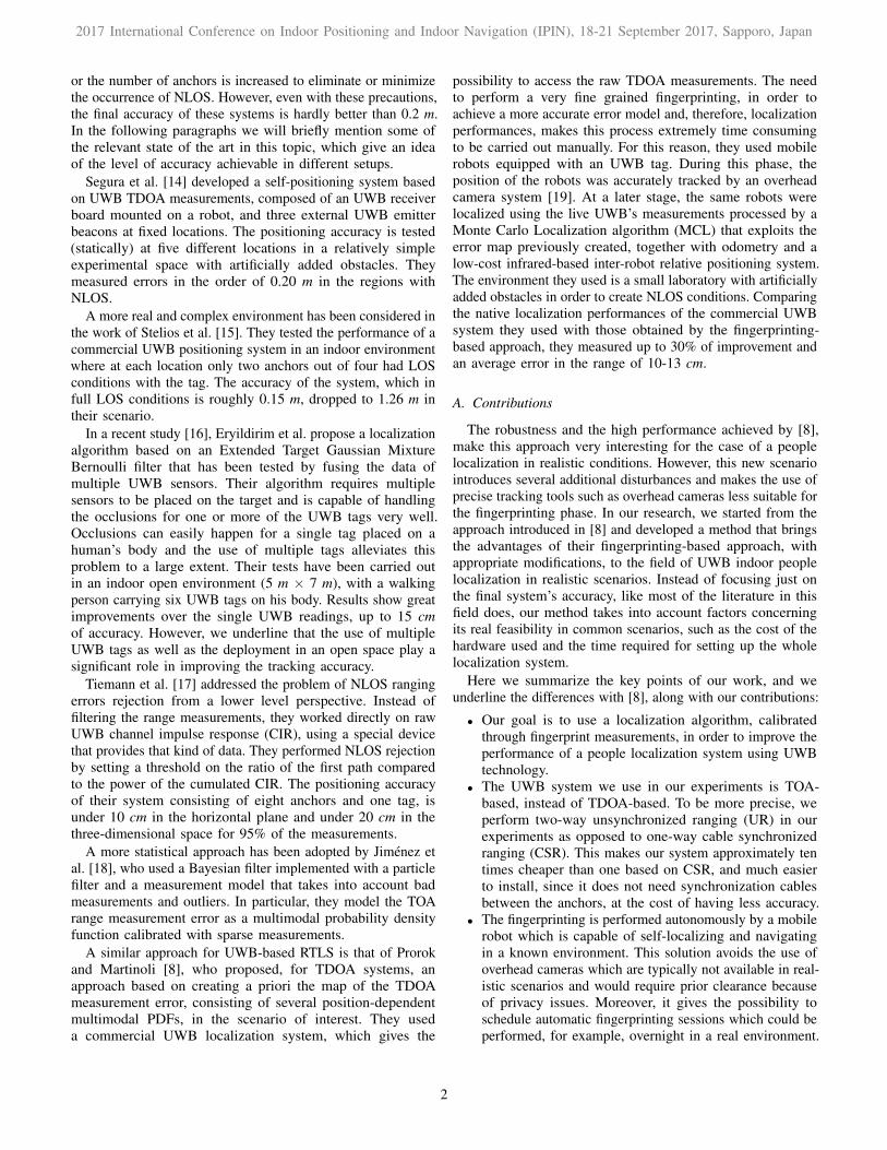
(a) (b)
Fig. 1: a) Robotic platform (MBot) used in our experiments toperform the automatic fingerprinting. b) Graphical view of therobot’s position estimation with AMCL. The blue dot is theposition estimate, while the red dots represent the measurementsof the laser range finders.
The second localization algorithm is the Monte CarloLocalization (MCL) [22]. The main advantage of this methodis that it is capable of exploiting the data of the fingerprintingphase and, for this reason, its performances will be comparedto those of the trilateration algorithm in order to evaluate theimprovements brought by our fingerprinting-based method. Thedetails of this method will be explained in Sec. III.
B. Robot
The robotic platform used in this work is shown in Fig. 1(a).This robot is called MBot [23] and has been developed withinthe FP7 European project MOnarCH (Multi-Robot CognitiveSystems Operating in Hospitals1). It is an omni-directionaldrive robot with an approximately round footprint of 0.65 m indiameter and a height of 0.98 m. It is provided with two laserrange finders placed on the lower part, between the base and therest of the robot, on both the front and the back for providingfull coverage. Two batteries give the robot an autonomy ofapproximately five hours, depending on the usage. The UWBtag can be connected via USB to the robot’s computer, whichruns Ubuntu desktop 12.04 and ROS Hydro. There exist anumber of software modules that compose the underlyinglayers of the robotic platform and provide functionalities suchas self-localization and navigation.
The robot’s self-localization feature has fundamental impor-tance in our work. It is based on AMCL (Adaptive Monte CarloLocalization) [24], a probabilistic localization algorithm for arobot moving in 2D. AMCL, a variation to the MCL abovementioned, provides an estimate of the position and orientationof the robot by matching the measurements of the laser rangefinders with a known map of the environment (see Fig. 1(b))and considering the odometry data. We underline that AMCLhas proven to be very robust against unknown obstacles likepeople (the laser range finders can detect only the legs), bagson the floor and closed/open doors. In the environment of ourtests we measured an average self-localization accuracy in theorder of 20 cm.
1http://monarch-fp7.eu/
3
2017 International Conference on Indoor Positioning and Indoor Navigation (IPIN), 18-21 September 2017, Sapporo, Japan
III. METHOD
Our method is an extension of [8] in order to address theproblem of people localization in a realistic environment. Itconsists of three main steps: (i) robotic fingerprinting, (ii)creation of the error map, (iii) localization. In this section, wewill explain the mentioned steps in more detail.
A. Robotic fingerprintingIn this phase, UWB measurements at multiple locations in
the scenario of interest need to be collected. Making use of aUR-based UWB system, each measurement mt is in the formof a pair (ru, xr), where ru is the tag-anchor distance and xris the position where the measurement has been taken, i.e., theposition of the robot performing the fingerprinting at that time.
As mentioned earlier, in [8] the ground-truth of the robotis measured through overhead cameras. The use of overheadcameras to get xr has several limitations: first of all, in a realscenario where multiple rooms have to be scanned, occlusionsand limited field of view may call for several cameras, whichare expensive, need precise calibration, and have to be allconnected to a central computer; secondly, the installation ofthis kind of system in a public environment may be faced withprivacy issues.
Consequently, we use the robot localization data to obtain xr.Although this does not provide the same accuracy as overheadcameras, the AMCL-based self-localization system of the robotis a good compromise between accuracy and usability in real-world scenarios.
When performing the fingerprinting the tag was mounted ona structure on the top of the robot, at an overall height of 170 cm.For better performances, different heights should be considered.The consequence of taking all the measurements at a fixedheight is that the accuracy of the error map will be maximumfor the localization of a person of that height. The fingerprintingpath was previously coded in the robot, so that it could follow itautomatically. The navigation capabilities of the robot allowedit to adapt the fingerprinting path in case of obstacles. Every30 cm, the robot stopped and took measurements at differentorientations, rotating around its vertical axis.
B. Error mapThe output of the first phase is a large quantity of UR
(range) measurements for each anchor and for many differentpositions and orientations in the environment. The goal of thesecond phase is to process this data in order to obtain a mapof the error. Our error map is divided into squared regions(1 m × 1 m) and describes the expected UR measurement error(ranging error) in each grid cell and for each anchor.
In more details, this error is described in the form of itsprobability density function (PDF). The PDF is computed start-ing from a general error model, in the form of a parametrizederror PDF, whose parameters are chosen in order to best fitour measurements.
The error model has been defined starting from [25] as amultimodal PDF. We can formulate it as follows:
p(∆r;θ) = pN (∆r) · PL + plnN (∆r − µN ) · (1− PL) (2)
where p(∆r;θ) indicates the probability density function ofmeasuring an error ∆r, pN (·) is a normal distribution of mean
0 1 2 3 4 50
0.2
0.4
0.6
0.8
1
1.2
Error [m]
Error PDF
PD
F
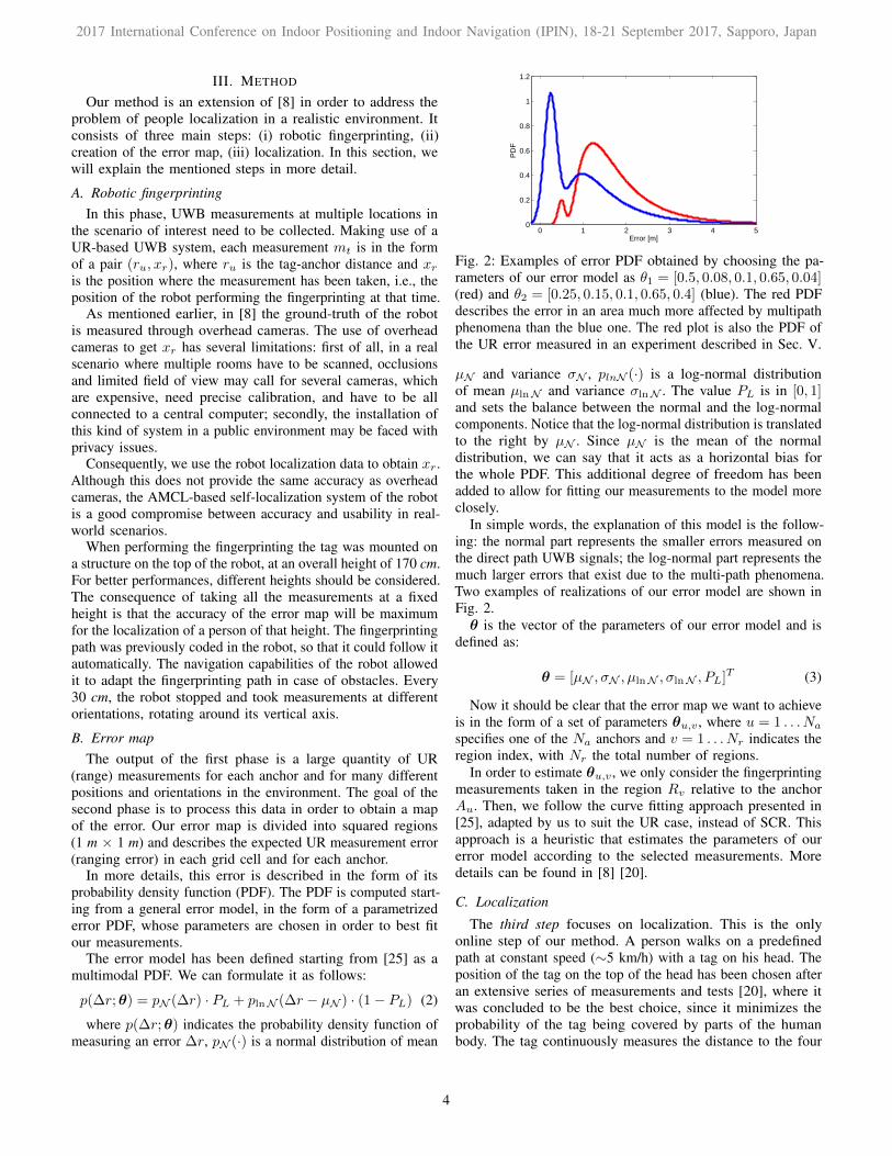
Fig. 2: Examples of error PDF obtained by choosing the pa-rameters of our error model as θ1 = [0.5, 0.08, 0.1, 0.65, 0.04](red) and θ2 = [0.25, 0.15, 0.1, 0.65, 0.4] (blue). The red PDFdescribes the error in an area much more affected by multipathphenomena than the blue one. The red plot is also the PDF ofthe UR error measured in an experiment described in Sec. V.
µN and variance σN , plnN (·) is a log-normal distributionof mean µlnN and variance σlnN . The value PL is in [0, 1]and sets the balance between the normal and the log-normalcomponents. Notice that the log-normal distribution is translatedto the right by µN . Since µN is the mean of the normaldistribution, we can say that it acts as a horizontal bias forthe whole PDF. This additional degree of freedom has beenadded to allow for fitting our measurements to the model moreclosely.
In simple words, the explanation of this model is the follow-ing: the normal part represents the smaller errors measured onthe direct path UWB signals; the log-normal part represents themuch larger errors that exist due to the multi-path phenomena.Two examples of realizations of our error model are shown inFig. 2.θ is the vector of the parameters of our error model and is
defined as:
θ = [µN , σN , µlnN , σlnN , PL]T (3)
Now it should be clear that the error map we want to achieveis in the form of a set of parameters θu,v , where u = 1 . . . Na
specifies one of the Na anchors and v = 1 . . . Nr indicates theregion index, with Nr the total number of regions.
In order to estimate θu,v , we only consider the fingerprintingmeasurements taken in the region Rv relative to the anchorAu. Then, we follow the curve fitting approach presented in[25], adapted by us to suit the UR case, instead of SCR. Thisapproach is a heuristic that estimates the parameters of ourerror model according to the selected measurements. Moredetails can be found in [8] [20].
C. Localization
The third step focuses on localization. This is the onlyonline step of our method. A person walks on a predefinedpath at constant speed (∼5 km/h) with a tag on his head. Theposition of the tag on the top of the head has been chosen afteran extensive series of measurements and tests [20], where itwas concluded to be the best choice, since it minimizes theprobability of the tag being covered by parts of the humanbody. The tag continuously measures the distance to the four
4
2017 International Conference on Indoor Positioning and Indoor Navigation (IPIN), 18-21 September 2017, Sapporo, Japan
anchors at an update rate of 4 Hz. Its measurements are readthrough its serial interface and stored for later processing.According to [8], an estimate of the tag’s position is obtainedusing MCL [22]. This algorithm uses a particle filter whereeach particle x[i] represents a position in three dimensions andits weight w[i] is computed considering the UWB measurementand the error map. We configured the height of the particlesaccording to the person’s height, which in our case is 170cm. The number of particles used by the particle filter M , isconfigurable and sets the balance between performance andcomputational complexity. In our case, 500 particles have beenused.
Algorithm 1 shows how MCL works in our application. First,the Initialization is performed by sampling the positionof the particles from a bidimensional Gaussian distributioncentered on the supposed person’s starting point. If the startingpoint is unknown, MCL can be initialized by spreading theparticles uniformly over the environment. After initializationeach particle has weight w0 = 1/M .
Then, the Update function uses the set of UR measuresMt = {rt,1 . . . rt,Na}, taken at time t from all the anchors, toupdate the weights of the particles according to equations
∆rt,u = |Au − x[i]t | − rt,u (4)
w[i]t =
Na∏u=1
p(∆rt,u; θu,v) (5)
where Au is the known position of the u-th anchor and θu,vis the vector of the parameters that characterize the error PDFassociated to the same u-th anchor in the region Rv, givenx[i]t ∈ Rv. At the end of the Update function, the positionUp of the person is estimated as the weighted average of allthe particles.
The next step is the Sample function: a resamplingalgorithm is used to select which particles to keep and whichto discard, according to their weight. In our case, we used thelow variance resampling algorithm explained in [26].
Finally, the Move function corresponds to the prediction stepof MCL, which aims at changing the position of the particlesaccording to the predicted next position of the tracked object.If available, for instance on a robotic platform, odometry dataare used in this step: the particles are moved according to themeasured translation of the robot. The lack of odometry datamakes people localization much more challenging. Despiteseveral methods such as the Kalman predictor can be usedto predict the movement of a person even without externaldata, in our case we consider the movement of the person ascompletely random, but limited in speed. For this reason theMove function simply applies a zero-mean Gaussian noise tothe 2D position of each particle. The variance σ2 of this noisehas to be chosen according to the sample rate of the algorithmand the supposed maximum speed of the person. In our casewe set σ2 = 0.25.
In order to test the improvements brought by the use of thefingerprinting data, the localization is computed independentlyusing directly the trilateration algorithm explained in SectionII-A (without fingerprinting) and the MCL (calibrated with
Algorithm 1 MCL
1: Initialization2: for t = 1 to ∞ do3: Xt = ∅4: for i = 1 to M do5: w
[i]t ← Update(Mt, x
[i]t )
6: Xt ← Xt ∪ 〈x[i]t , w[i]t 〉
7: end for8: Up =
∑i w
[i]x[i]∑i w
[i]
9: for i = 1 to M do10: x[i]t ← Sample(Xt)
11: x[i]t+1 ← Move(x[i]t )
12: end for13: end for
fingerprinting). The same UWB UR measurements collectedin our tests were used as input for both algorithms.
IV. SETUP AND EXPERIMENTS
We considered two different scenarios of incrementallyincreasing complexity and scope (see Fig. 3). For simplicitywe will call them (E1) and (E2). The area of the testingenvironment for (E1) is approximately 100 m2 while for (E2)it is three times larger. In some locations of (E2) we haveup to four walls between the tag and an anchor. This is anextremely challenging condition for a radio-based localizationsystem. Moreover, in (E2) we have on the left-hand side ofthe corridor (refer to the scheme in Fig. 3) several metalliccabinets, that challenge the UWB system even more. However,all the walls are non-bearing.
We tested also the case of bearing walls in the line between atag and an anchor and we noticed that this condition makes theperformance of the system drastically decrease, probably dueto the metallic structural elements they have inside. The choiceof such realistic scenarios is given by our goal of consideringa real use case with a limited number of anchors in order tokeep the cost and complexity of the overall system low, eventhough we know it has a negative impact on the localizationaccuracy. The anchors, indicated in the figures with letter A,have been installed at an height of 2.51 m, close to the ceiling.Their position has been measured in our coordinate systemvery accurately with the help of a laser meter.
For the fingerprinting phase, the robot has been programmedin order to autonomously scan the environment. Roughly1200 measurements per squared meter have been taken, at12 orientations around the vertical axis.
During the localization phase a person was walking witha tag on his head along the path indicated by the blue line.In order to record the UR measurements outputted by thetag, the person was walking carrying a bag with a laptopconnected via USB to the tag. The groundtruth of the personhas been computed by precisely measuring the time taken bythe person to walk between the various checkpoints at constantspeed. Although, it is theoretically possible to compute thelocalization estimate online, we did it offline on the basis ofthe measurements collected.
5
2017 International Conference on Indoor Positioning and Indoor Navigation (IPIN), 18-21 September 2017, Sapporo, Japan
x [m]
y [m
]
Measurements on inter−rooms path
−1 0 1 2 3 4 5 6 7 8 9 10 11 12 13 14 150
1
2
3
4
5
6
7
8
9
(a) (E1) - Trilateration algorithm
x [m]
y [m
]
Eliko UWB − Particle filter
−1 0 1 2 3 4 5 6 7 8 9 10 11 12 13 14 150
1
2
3
4
5
6
7
8
9
Anchor DStart
(b) (E1) - MCL calibrated with fingerprints
x [m]
y [m
]
−8 −6 −4 −2 0 2 4 6
0
2
4
6
8
10
12
14
16
18
20
22
24
(c) (E2) - Trilateration algorithm
x [m]
y [m
]
−8 −6 −4 −2 0 2 4 6
0
2
4
6
8
10
12
14
16
18
20
22
24
(d) (E2) - MCL calibrated with fingerprints
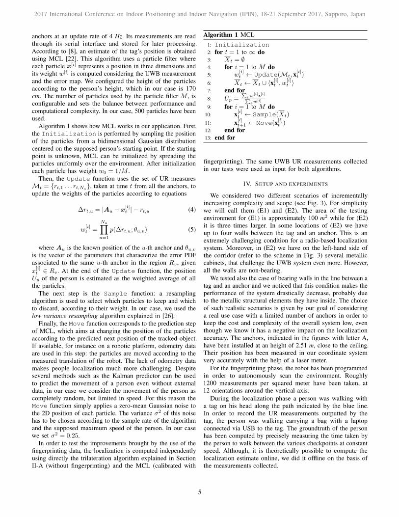
Fig. 3: Tracking results on first (a-b) and second (c-d) scenarios using the trilateration (a-c) and MCL calibrated with fingerprints(b-d). The blue line is the path of the walking person, while the red lines show the error between the location estimates andtheir corresponding true positions. Notice how, particularly in the second segment of the path, the accuracy is higher using thefingerprinting-calibrated method.
To have an idea about the accuracy of camera-based trackingsolutions compared to the UWB localization methods used inthis study, we have made assessments using a marker-basedtracking system (SwisTrack) [19] with an overhead camera, anda marker-less solution used in [27] with an omni-directionalceiling mounted-camera. The covering area of the two methodswere substantially smaller for a single camera compared to thearea covered by the UWB solution. A realistic estimate of themaximum error across the entire arena is in the order of 0.02 mand 0.2 m for the aforementioned marker-based and marker-less solutions, respectively (refer to Sec. V for comparison).An obvious benefit of using UWB systems is the ability toovercome the field of view limitations of camera-based trackingsystems. In this study, we were only allowed to use camerasin the laboratory area due to privacy issues. In general, it canhappen in many cases that the entire environment cannot becovered by overhead cameras and hence UWB systems have asignificant advantage therein.
V. RESULTS
Fig. 3a and 3b compare the results obtained in the firstscenario using the trilateration algorithm (a) and MCL cal-ibrated through fingerprinting (b). The red lines show thecorrespondence between the true position of the person andthe estimated one. Let us start our analysis of the resultsconsidering the first environment (E1). We can clearly see that,using trilateration, in the second segment of the path the erroris particularly high, reaching the maximum value of 3.75 m,while in the rest of the path the average error is 0.36 m.
The red curve of Fig. 2 shows, as resulted by the finger-printing process, the UR error PDF measured in the secondsegment of the path in (E1), with respect to anchor D. Theinterpretation of this PDF is that in the second segment ofthe path, the distance between the tag and the anchor D ismeasured with a high positive bias. This behavior is probablydue to the presence of multiple walls on the direct path betweenthese two transceivers. This fact also justifies the right bias ofthe location estimates, as observed in Fig. 3a.
6
2017 International Conference on Indoor Positioning and Indoor Navigation (IPIN), 18-21 September 2017, Sapporo, Japan
0 1 2 3 40
20
40
60
80
100
Error [m]
CD
F [%
]
MCL E1MCL E2Trilat. E1Trilat. E2
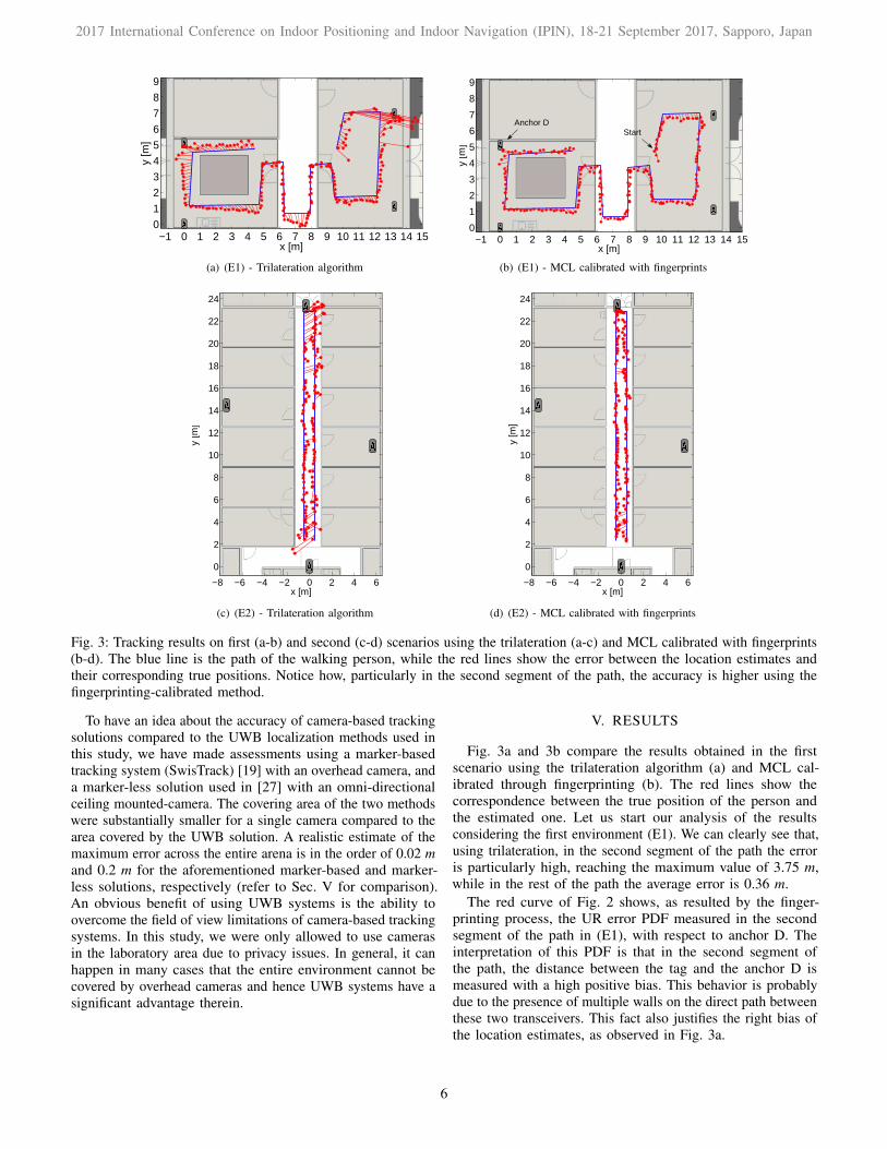
Fig. 4: Cumulative distribution function (CDF) of the errormeasured in the two scenarios (E1,E2) using the trilaterationalgorithm and MCL calibrated via robotic fingerprinting. Noticethat with the latter method, the errors above one meter arecompletely cancelled.
Using the MCL algorithm that exploits the fingerprintingdata, we obtained the results shown in Fig. 3b. In particular, wecan see that we had a great improvement in the second segmentof the path, were the right bias has disappeared and the errorhas reached the same level as the rest of the path. Consideringthe whole path, the mean error decreased from 0.51 m to 0.25m, that is roughly 50% of improvement. However, given thenon-uniform distribution of the error, in Fig. 4 we show itsCumulative Distribution Function (CDF), which gives a betteroverview of the improvements achieved.
The error CDF shows that our method is less effective againsterrors lower than 0.30 m, while it works very well againsthigher errors. This behavior is due to approximations introducedby our general UR error model, the usage of the ground-truth provided by AMCL, the assumption of Gaussian uniformmotion model of the human, limited number of measurementsin the fingerprinting phase, etc. For many applications, suchas people escorting with robots, localizing a person in a circleof 0.50 m radius is sufficient. Considering this value as ourthreshold, we measured that our method increased the numberof measurements below this threshold from 70% to 98% usingonly a single tag.
The results for the second scenario, are shown in Fig. 3cand 3d. The anchors are still indicated with the letter “A”. Wejust considered the central corridor and not the rooms, since itis sufficiently complex for our needs.
Comparing the results obtained using the trilateration al-gorithm and fingerprinting-calibrated MCL, we noticed that,similar to the first scenario, most of the improvements havebeen brought in the areas which were affected by higher errors:in our case at the top and bottom parts of the map. In thecentral part of the map, we measured better performances giventhe lower number of obstacles in the tag-anchor line. The meanerror, along the whole path, in the trilateration and MCL casesare respectively 0.48 m and 0.25 m, confirming an improvementof roughly 50%. The CDF of the error for both the algorithmsin this second scenario are shown as the dotted lines, in Fig. 4.Notice that the use of fingerprinting-calibrated MCL made thepercentage of localization errors below 0.50 m increase from76% to 94%. Table I summarizes the results discussed so far.
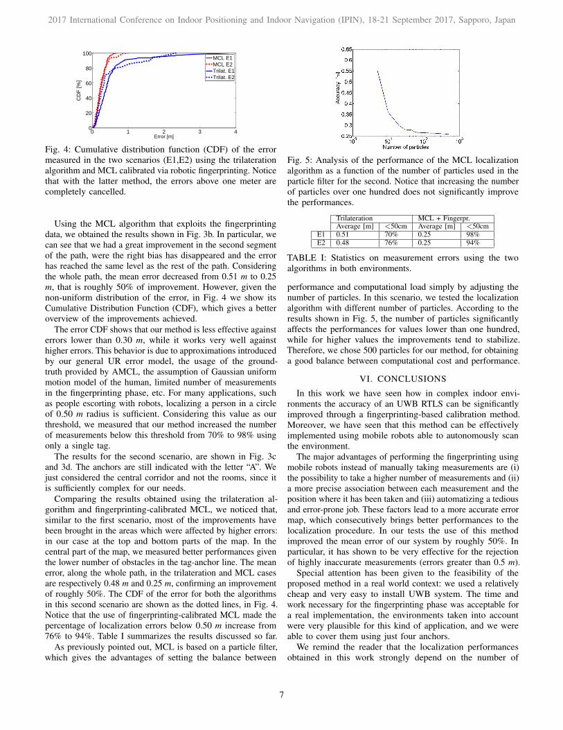
As previously pointed out, MCL is based on a particle filter,which gives the advantages of setting the balance between
Fig. 5: Analysis of the performance of the MCL localizationalgorithm as a function of the number of particles used in theparticle filter for the second. Notice that increasing the numberof particles over one hundred does not significantly improvethe performances.
Trilateration MCL + Fingerpr.Average [m] <50cm Average [m] <50cm
E1 0.51 70% 0.25 98%E2 0.48 76% 0.25 94%
TABLE I: Statistics on measurement errors using the twoalgorithms in both environments.
performance and computational load simply by adjusting thenumber of particles. In this scenario, we tested the localizationalgorithm with different number of particles. According to theresults shown in Fig. 5, the number of particles significantlyaffects the performances for values lower than one hundred,while for higher values the improvements tend to stabilize.Therefore, we chose 500 particles for our method, for obtaininga good balance between computational cost and performance.
VI. CONCLUSIONS
In this work we have seen how in complex indoor envi-ronments the accuracy of an UWB RTLS can be significantlyimproved through a fingerprinting-based calibration method.Moreover, we have seen that this method can be effectivelyimplemented using mobile robots able to autonomously scanthe environment.
The major advantages of performing the fingerprinting usingmobile robots instead of manually taking measurements are (i)the possibility to take a higher number of measurements and (ii)a more precise association between each measurement and theposition where it has been taken and (iii) automatizing a tediousand error-prone job. These factors lead to a more accurate errormap, which consecutively brings better performances to thelocalization procedure. In our tests the use of this methodimproved the mean error of our system by roughly 50%. Inparticular, it has shown to be very effective for the rejectionof highly inaccurate measurements (errors greater than 0.5 m).
Special attention has been given to the feasibility of theproposed method in a real world context: we used a relativelycheap and very easy to install UWB system. The time andwork necessary for the fingerprinting phase was acceptable fora real implementation, the environments taken into accountwere very plausible for this kind of application, and we wereable to cover them using just four anchors.
We remind the reader that the localization performancesobtained in this work strongly depend on the number of
7
2017 International Conference on Indoor Positioning and Indoor Navigation (IPIN), 18-21 September 2017, Sapporo, Japan
measurements taken during the fingerprinting phase and on theaccuracy of the robot self-localization system. Improving thesetwo factors would probably lead to even better results. In areal-world scenario, considerable changes in the environmentin terms of number of humans, the height at which the tagis placed, placement or removing of large metallic objects,etc., may require recalibration of the localization algorithm.Although this entails additional effort, thanks to the automationof the proposed method, the recalibration process can beperformed fairly quickly. The approach presented in thispaper can be easily extended to work in three dimensions.Providing the robots with multiple sensors in order to collectdata at different heights can be a solution which will notcause the fingerprinting process to take more time. Instead,the computational power needed for MCL will significantlyincrease, given the larger number of particles that must beconsidered.
In conclusion, our work has shown how UWB, an emergingtechnology in the field of RTLS, can be combined with mobilerobots and state-of-the-art localization algorithms to provide acomplete, cheap and feasible people tracking solution, able toreach an accuracy of approximately 0.25 m even in realisticindoor scenarios.
ACKNOWLEDGEMENTS
We thank all the people of the DISAL lab at EPFL and, inparticular, Jose Nuno Pereira, for their support given to thiswork. We are also grateful to Amanda Prorok, whose workinspired this research and who gave useful hints on how toapproach a field she has a lot of experience in. Finally, we arealso immensely grateful to Rodrigo Ventura for his assistanceand contribution to the navigation components of the softwarestack of MOnarCH.
REFERENCES
[1] M. G. Wing, A. Eklund, and L. D. Kellogg, “Consumer-grade globalpositioning system (gps) accuracy andrreliability,” Journal of forestry,vol. 103, no. 4, pp. 169–173, 2005.
[2] F. Seco, A. Jimenez, C. Prieto, J. Roa, and K. Koutsou, “A surveyof mathematical methods for indoor localization,” Intelligent SignalProcessing, pp. 9–14, 2009.
[3] I. Sharp and K. Yu, “Enhanced least-squares positioning algorithm forindoor positioning,” IEEE Transactions on Mobile Computing, vol. 12,no. 8, pp. 1640–1650, 2013.
[4] J. Yang and Y. Chen, “Indoor localization using improved rss-basedlateration methods,” in IEEE Global Telecommunications Conference,2009, pp. 1–6.
[5] V. Honkavirta, T. Perala, S. Ali-Loytty, and R. Piche, “A comparativesurvey of wlan location fingerprinting methods,” in 6th IEEE Workshopon Positioning, Navigation and Communication, pp. 243–251, 2009.
[6] K. Kaemarungsi and P. Krishnamurthy, “Modeling of indoor positioningsystems based on location fingerprinting,” in Twenty-third Annual JointConference of the IEEE Computer and Communications Societies, vol. 2,pp. 1012–1022, 2004.
[7] P. Bahl and V. N. Padmanabhan, “Radar: An in-building RF-based userlocation and tracking system,” in Nineteenth Annual Joint Conference ofthe IEEE Computer and Communications Societies. Proceedings, vol. 2,pp. 775–784, 2000.
[8] A. Prorok and A. Martinoli, “Accurate indoor localization with Ultra-Wide Band using spatial models and collaboration,” The InternationalJournal of Robotics Research, vol. 33, no. 4, pp. 547–568, 2014.
[9] D. Rejane, V. Thierry, and B. Adrien Van Den, “Comparison ofindoor localization systems based on wireless communications,” WirelessEngineering and Technology, 2011.
[10] A. Disha, “A comparative analysis on indoor positioning techniquesand systems,” International Journal of Engineering Research andApplications, vol. 3, pp. 1790–1796, 2013.
[11] A. Alarifi, A. Al-Salman, M. Alsaleh, A. Alnafessah, S. Al-Hadhrami,M. A. Al-Ammar, and H. S. Al-Khalifa, “Ultra-Wide Band indoorpositioning technologies: Analysis and recent advances,” Sensors, vol. 16,no. 5, p. 707, 2016.
[12] S. Gezici and H. V. Poor, “Position estimation via Ultra-Wide Bandsignals,” Proceedings of the IEEE, vol. 97, no. 2, pp. 386–403, 2009.
[13] M. Yavari and B. G. Nickerson, “Ultra wide band wireless positioningsystems,” Dept. Faculty Comput. Sci., Univ. New Brunswick, Fredericton,NB, Canada, Tech. Rep. TR14-230, 2014.
[14] M. Segura, H. Hashemi, C. Sisterna, and V. Mut, “Experimentaldemonstration of self-localized ultra wide band indoor mobile robotnavigation system,” in International Conference on Indoor Positioningand Indoor Navigation, pp. 1–9, 2010.
[15] M. A. Stelios, A. D. Nick, M. T. Effie, K. M. Dimitris, and S. C.Thomopoulos, “An indoor localization platform for ambient assisted livingusing UWB,” in Proceedings of the 6th ACM International Conferenceon Advances in Mobile Computing and Multimedia, pp. 178–182, 2008.
[16] A. Eryildirim and M. B. Guldogan, “A gaussian mixture bernoulli filterfor extended target tracking with application to an localization system,”Digital Signal Processing, vol. 57, pp. 1–12, 2016.
[17] J. Tiemann, F. Schweikowski, and C. Wietfeld, “Design of an UWBindoor-positioning system for UAV navigation in gnss-denied environ-ments,” in Indoor Positioning and Indoor Navigation (IPIN), 2015International Conference on, pp. 1–7, IEEE, 2015.
[18] A. R. J. Ruiz and F. S. Granja, “Comparing Ubisense, BeSpoon, andDecaWave UWB location systems: Indoor performance analysis,” IEEETransactions on Instrumentation and Measurement, 2017.
[19] T. Lochmatter, P. Roduit, C. Cianci, N. Correll, J. Jacot, and A. Martinoli,“Swistrack-a flexible open source tracking software for multi-agentsystems,” in 2008 IEEE/RSJ International Conference on IntelligentRobots and Systems, pp. 4004–4010, 2008.
[20] A. Canepa, “Methods for ultra wide band indoor localization using roboticfingerprinting in complex environments,” Master’s thesis, Politecnico diTorino and Ecole Polytechnique Federale de Lausanne, DISAL-MP26,2015.
[21] C. Zhang, M. Kuhn, B. Merkl, A. E. Fathy, and M. Mahfouz, “Accurateuwb indoor localization system utilizing time difference of arrivalapproach,” in IEEE Radio and Wireless Symposium, 2006.
[22] S. Thrun, W. Burgard, and D. Fox, Probabilistic robotics. MIT press,2005.
[23] J. Messias, R. Ventura, P. Lima, J. Sequeira, P. Alvito, C. Marques,and P. Carrico, “A robotic platform for edutainment activities in apediatric hospital,” in IEEE International Conference on AutonomousRobot Systems and Competitions, pp. 193–198, IEEE, 2014.
[24] D. Fox, “Kld-sampling: Adaptive particle filters,” in Advances in neuralinformation processing systems, pp. 713–720, 2001.
[25] A. Prorok, P. Tome, and A. Martinoli, “Accommodation of NLOS forultra-wideband TDOA localization in single and multi-robot systems,”in Proceedings of the International Conference on Indoor Positioningand Indoor Navigation, DOI:10.1109/IPIN.2011.6071927, 2011.
[26] S. Thrun, W. Burgard, and D. Fox, Probabilistic Robotics. MIT press,2005.
[27] Z. Talebpour, D. Viswanathan, R. Ventura, G. Englebienne, and A. Marti-noli, “Incorporating perception uncertainty in human-aware navigation: Acomparative study,” in IEEE Int. Symp. on Robot and Human InteractiveCommunication, 2016.
8