Embed Size (px)
Citation preview

MADE IN THE U.S.A.
W-37 ABGAUTOMATIC BAND GRINDER
RIGHT ACHINE
OPERATOR'S MANUAL

W-37 ABG
�
Revised 9-2012
LIMITED WARRANTYThis machine is warranted against defects in workmanship and materials under normal use and proper maintenance, for one year after date of purchase from WRIGHT MACHINE TOOL CO. Any part which is determined to be defective in material or workmanship and returned to WRIGHT MACHINE TOOL CO., shipping costs prepaid will be repaired or replaced, at WRIGHT MACHINE TOOL CO. option.
WRIGHT MACHINE TOOL CO., INC. Phone (541) 942-3712365 Palmer Avenue Fax (541) 942-0730Cottage Grove, Oregon 97424
Contents
LIMITED WARRANTY ...................................................................................................................... �GENERAL SAFETY RULES............................................................................................................. 2SPECIFICATIONS ............................................................................................................................ 3FEATURES ....................................................................................................................................... 4OPTIONS ......................................................................................................................................... 5COMMON REPLACEMENT PARTS ................................................................................................ 5PRE SETUP ..................................................................................................................................... 5BAND GUIDE ASSEMBLY ............................................................................................................... 6OPERATION ..................................................................................................................................... 7DRESSING THE GRINDING WHEEL.............................................................................................8BAND GUIDE BAR ASSEMBLY ....................................................................................................... 9GRINDING WHEEL ADJUSTMENT ............................................................................................... �0MAINTENANCE ............................................................................................................................. ��TROUBLE SHOOTING .................................................................................................................. ��FRONT VIEW OF HEAD ASSEMBLY ............................................................................................ �2SIDE VIEW OF HEAD ASSEMBLY ................................................................................................ �3FRONT VIEW OF CLAMP / INDEX AREA ASSEMBLY ................................................................. �4CLAMP PIVOT ASSEMBLY ............................................................................................................ �5FIXED CLAMP JAW ASSEMBLY ................................................................................................... �6MOVABLE CLAMP JAW ASSEMBLY ............................................................................................. �7INDEX PAW ASSEMBLY ................................................................................................................ �8HEAD ACTUATOR ASSEMBLY ..................................................................................................... �9PRIMARY INDEX ARM ASSEMBLY ............................................................................................... 20ELECTRICAL SCHEMATIC ............................................................................................................ 23

W-37 ABG
2
Revised 9-2012
GENERAL SAFETY RULESFailure to follow the Safety Rules and other basic precautions, may result in
serious injury.
Always use eye protection: When operating this machine, eye protection should be worn. Grinding particles and the possibility of wheel breakage make eye protection necessary. Also face or dust mask if operation is dusty. Use adequate ventilation.
Use ear protection: If operation is creating excessive noise.
Disconnect power: To machine when NOT in use.
Keep clear: Of grinding wheels and pinch points when machine is running.
Saws are sharp: Wear appropriate personal protective equipment when handling saw blades.
Mounting of wheels: Should only be done by persons with mechanical aptitude and good knowledge of mounting, care, and inspection of grinding wheels. Wheels must be rated for the RPM of the machine.
Dress properly: Do not wear loose clothing or jewelry. Nonskid foot wear is recom-mended. Wear protective hair covering to contain long hair.
Avoid dangerous environments: Don’t use in wet location. Keep work area well lit. Do not use this machine in the presence of flammable liquid or gasses.
Keep children away: Do not let VISITORS contact this machine.
Keep work area clean: Cluttered areas invite accidents.
All electrical covers: Must be in place before applying electrical power to this ma-chine. Electrical service must be locked out prior to removing any electrical covers or machine guards. Access to electrical components must be restricted to trained personnel only to avoid possible electrical shock.
Voltage greater: Than specified on name plate can result in serious injury to user.
Follow safety precautions: For wheels, coolant and material being ground. These items must also be compatible. This information is available on the Safety Data sheet for each of these products.

W-37 ABG
3
Revised 9-2012
SPECIFICATIONS
STANDARD VOLTAGE: ��5 Volt, � Phase, 60 HZ
OPTIONAL VOLTAGE: 230 Volt, � Phase, 50 HZ
SHIPPING WEIGHT: �20 lbs. (each box is 60 lbs.)
CRATE SIZE: L �8" X W �8" X H �8" (2 boxes)
AIR REQUIREMENTS: N / A
STANDARD SAW SIZE: �" - 3"
OPTIONAL SAW SIZE: �/2" - �"
RANGE OF HOOK ANGLE: 0 to �5 Degrees
SPINDLE MOTOR: �/8 H.P., � Phase, 3000 R.P.M. Motor
CAM MOTOR: �/20 H.P., � Phase, 30 R.P.M. Motor
W-37 ABG
4
Revised 9-2012
Features The W-37 ABG achieves cost effective automatic sharpening of narrow band saws. Saws that have been considered disposable now can be resharpened many times, which greatly reduces saw cost. Operation is simple and the total labor per resharpening is only a few minutes.
The "W-37 ABG" features include:- Straight Line Head Movement- Ball Linear Slide- Built In Saw Support- Quick Open Clamp Jaws- Adjustable Clamp Drag- Precision Cams- Simple to Operate- Excellent Sharpness- Low Maintenance- Quick Setup
Notice W-37 ABG series products and the information in this user guide are the proprietary property of Wright Machine Tool Co. Inc. or its licensors and may not be copied, disclosed, or used for any purpose not expressly authorized by the user thereof.
Wright Machine Tool Co. Inc. is constantly seeking ways to improve its entire product line of machinery, and therefor reserves the right to change this manual and hardware mentioned therein at any time without notice.
In no event will the provider of this equipment be liable for any incidental, consequential, or special damages of any kind or nature whatsoever, including but not limited to lost profits arising from or in any way connected with the use of the equipment or this user manual.
Safety First!
TECHNICAL Bench mountable, the W-37 ABG is a compact, self contained package with band supports built in. One cam set for a single tooth shape comes standard with the machine. Cam changing time is less than five minutes allowing many band shapes to be sharpened. Built to give years of trouble free service with sealed ball bearings used through out. Straight line movement on the grinding head assures correct tooth geometry as the grind wheel diameter changes.

W-37 ABG
5
Revised 9-2012
OPTIONS
Band Support with 30" Extension W-�256-20Small Bands Support for �/2" to �" Bands Call for Details
COMMON REPLACEMENT PARTS
Finger Arm Pivot Bearing W-�89Ramp Follower W-�268Feed Finger Arm Assy. W-�267-AFinger Arm Spring/Head Pivot Spring W-384Fixed Clamp Jaw W-�26�Movable Clamp Jaw W-�260Cam Follower W-�88Saw Guide W-�259Bearing Sleeve W-282Bearing Bushing W-283Grinding Wheel V-�8
PRE SETUP
MOUNTING GRINDING WHEELSAll grinding wheels must be rated for the RPM of this machine. Wheels ex-
posed to higher than rated RPM are dangerous.Mounting of the grinding wheel should only be done by persons with mechanical apti-tude and good knowledge of mounting, care, and inspection of grinding wheels.
W-37 ABG
6
Revised 9-2012
Automatic Band Grinder
The W-37 ABG is designed to profile grind narrow band saw blades. The tooth shape is determined by the cam set that is installed on the machine. If other tooth shapes are required a different cam set will be necessary. Cams can be purchased to accommodate most tooth shapes. Include a sample of the tooth shape when ordering these cams.
The standard machine is set up to grind a �0 degree hook angle. If other angles are required please specify at time of purchase.
Band Guide Assembly
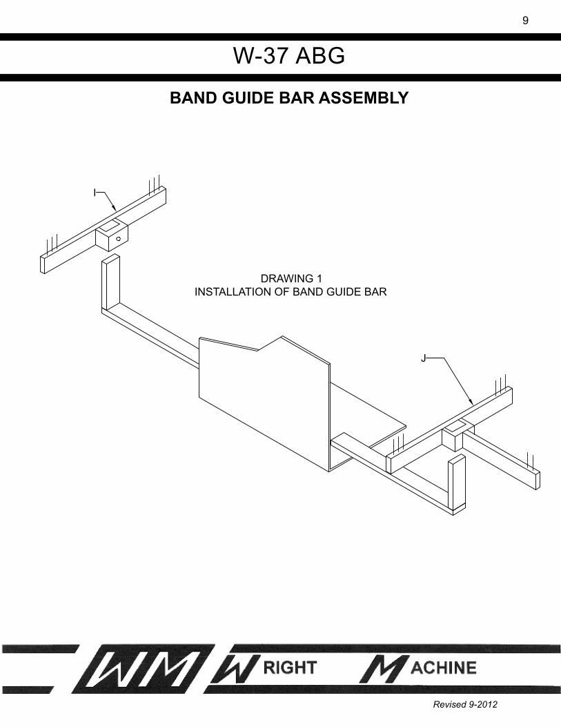
�. Install band guide bar as shown in drawing #� using the two 5/�6 bolts that are included.
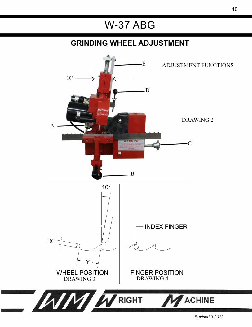
2. Install the grinding head at an approximately �0 degree angle as shown in drawing #2. Lock the head by firmly tightening handle (A).
3. The W-37 ABG must be mounted to work surface before using.
4. Install grinding wheel on the machine. All wheels used on this machine must be rated for at least 3500 R.P.M.
Warning
Eye protection must be worn when operating this machine. Grinding wheels can explode and caution must be used when operating this machine.

W-37 ABG
7
Revised 9-2012
OPERATION�. Use protractor to set hook angle. This angle must match specified angle for cam. Use clamp for 0 degree.
2. Install the band in the guide bars with the band running between the roller guides. Band must be level. Use protractor to level band with clamp.
3. Adjust knob (B) on drawing #2 until the band gullet is aligned with the index finger as shown on drawing #4.
4. Adjust band guide (J) drawing #� until the band is level. Be sure that part # W-�268 rides on fixed jaw when index is full forward.
5. Now adjust band guide (I) drawing #� until there is a �/8" clearance between the bottom of the band and top of the guide. This step is most important because we can only support the band in two points. If both band guides are contacting the saw, the grind will be erratic because the back of the band is not straight.
6. Start the gear motor and grinding head. Adjustment (C) drawing #2 controls the amount of material that is removed from the face of the tooth, (X) on drawing #3.
7. Knob (D) controls the amount of material that is removed from the back and gullet of the tooth, (Y) on drawing #3.
8. Do not overheat the band when sharpening. If the band is turning blue on the cutting edge or bottom of the gullet, it will soften the band or cause it to crack.
Note: Tooth shape is determined by cam design, wheel shape and the angle the band travels under the wheel. To grind the tooth shape that the cam is designed for, requires the wheel to be dressed on a full radius and the band must be set horizontal.
W-37 ABG
8
Revised 9-2012
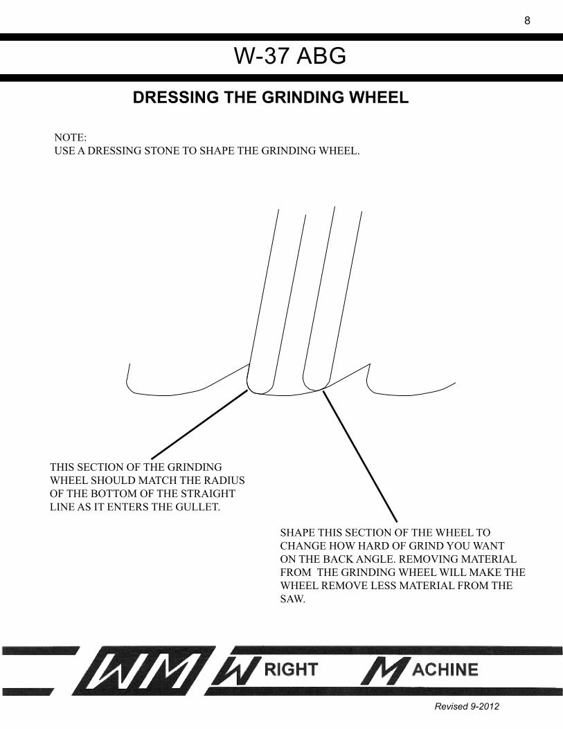
DRESSING THE GRINDING WHEEL
SHAPE THIS SECTION OF THE WHEEL TO CHANGE HOW HARD OF GRIND YOU WANT ON THE BACK ANGLE. REMOVING MATERIAL FROM THE GRINDING WHEEL WILL MAKE THE WHEEL REMOVE LESS MATERIAL FROM THE SAW.
THIS SECTION OF THE GRINDING WHEEL SHOULD MATCH THE RADIUS OF THE BOTTOM OF THE STRAIGHT LINE AS IT ENTERS THE GULLET.
NOTE:USE A DRESSING STONE TO SHAPE THE GRINDING WHEEL.
W-37 ABG
9
Revised 9-2012
BAND GUIDE BAR ASSEMBLY
DRAWING �INSTALLATION OF BAND GUIDE BAR
J
I
W-37 ABG
�0
Revised 9-2012
GRINDING WHEEL ADJUSTMENT
DRAWING 2
ADJUSTMENT FUNCTIONSE
B
C
A
D
X
Y
10°
INDEX FINGER
FINGER POSITIONWHEEL POSITIONDRAWING 4DRAWING 3
10°

W-37 ABG
��
Revised 9-2012
MAINTENANCE Care should be taken when cam cover is removed. Do not allow any grinding grit to enter. Be sure that cams are clean and dry and cam followers are regularly maintained.
TROUBLE SHOOTING
CAUTION: DISCONNECT FROM POWER BEFORE OPENING ANY COVER.
Machine will not start with switch on.
�. No power to machine. Is machine plugged in? 2. Check for tripped breaker or blown fuse on outlet.
Band rises as machine cycles.
�. Check to see if band is level and that the band guides are in proper position. 2. Check the runway under the band clamp and adjust properly.
Machine runs but will not go through it's cycle.
�. Inspect the cam and cam followers. Make sure that the cam rotates fully and that the followers are making full contact with the cam 2. Cam drive motor is defective. If other problems arise please call us for technical advice. 1 (541) 942-3712.

W-37 ABG
�2
Revised 9-2012
FRONT VIEW OF HEAD ASSEMBLY

W-37 ABG
�3
Revised 9-2012
SIDE VIEW OF HEAD ASSEMBLY
W-501HEAD ARM
W-505 GUIDE
W-506 GUIDE ROD
W-508TOMSON SHAFT
F-1491
4-20 X 3-12 SHCS
W-1273LOCKUP
F-1571
4-20 SHOULDER BOLT
W-502WHEEL GUARD
W-537PIVOT PIN
F-1105
16-18 X 3 4 SHCS
W-1251-1BASE
W-37 ABG
�4
Revised 9-2012
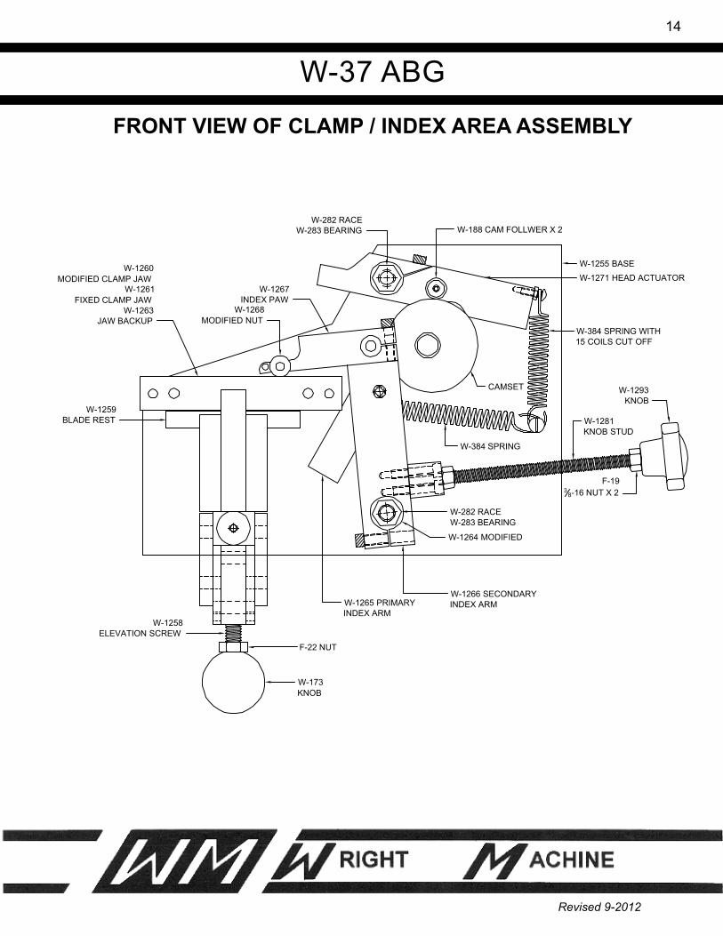
FRONT VIEW OF CLAMP / INDEX AREA ASSEMBLY
W-1293KNOB
F-193
8-16 NUT X 2
W-1281KNOB STUD
W-384 SPRING WITH15 COILS CUT OFF
W-384 SPRING
W-1255 BASE
W-188 CAM FOLLWER X 2W-282 RACE
W-283 BEARING
W-1271 HEAD ACTUATORW-1267
INDEX PAWW-1268
MODIFIED NUT
W-1260MODIFIED CLAMP JAW
W-1261FIXED CLAMP JAW
W-1263JAW BACKUP
CAMSET
W-1259BLADE REST
W-1258ELEVATION SCREW
W-173KNOB
F-22 NUT
W-1265 PRIMARYINDEX ARM
W-1266 SECONDARYINDEX ARM
W-282 RACEW-283 BEARING
W-1264 MODIFIED
W-37 ABG
�5
Revised 9-2012
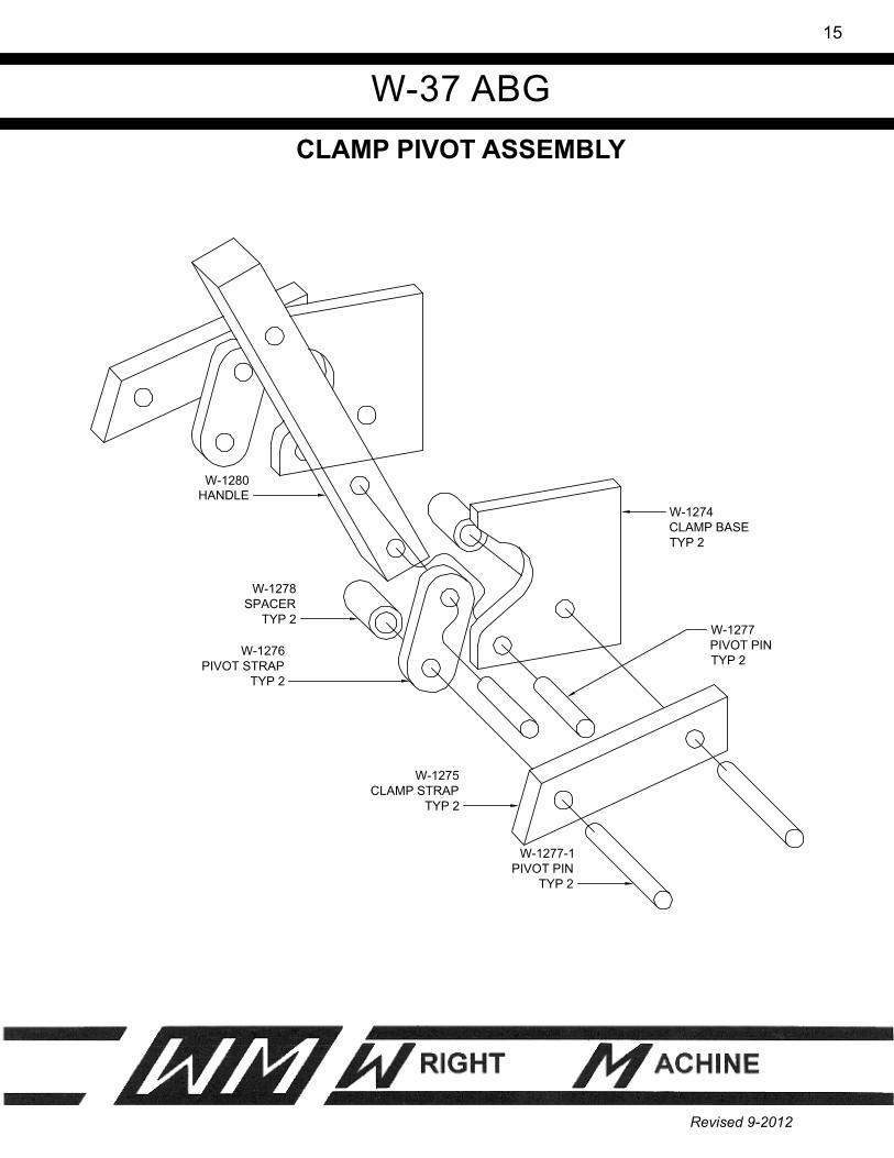
CLAMP PIVOT ASSEMBLY
W-1278SPACER
TYP 2
W-1277-1PIVOT PIN
TYP 2
W-1275CLAMP STRAP
TYP 2
W-1274CLAMP BASETYP 2
W-1276PIVOT STRAP
TYP 2
W-1277PIVOT PINTYP 2
W-1280HANDLE

W-37 ABG
�6
Revised 9-2012
FIXED CLAMP JAW ASSEMBLY
F-107TYP 2
W-1261INNER CLAMP JAW
W-1262JAW SPACER
F-404
F-110
W-537 PIVOT PIN
F-25TYP 2
W-1255BASE

W-37 ABG
�7
Revised 9-2012
MOVABLE CLAMP JAW ASSEMBLY
W-1263JAW BACK UP
W-1260OUTSIDE JAW
F-106 X 2
F-399 X 2

W-37 ABG
�8
Revised 9-2012
INDEX PAW ASSEMBLYW-1267-A
F-104 14-20 X 1 SHCS
W-1267INDEX PAW
W-189CAM FOLLOWER
F-10214-20 X 34 SHCS
W-1268MODIFIED NUT
F-4203
16 X 1 DOWL PIN

W-37 ABG
�9
Revised 9-2012
HEAD ACTUATOR ASSEMBLY
F-61MWASHER
W-188BEARING
W-61MWASHER
F-35814-20 X 34 BHCS
F-33810-24 X 5
8 RND HD SLOT SCREW
W-384-2SPRING
F-1110-24 NUT
F-10114-20 X 58 SHCS
W-1271HEAD ACTUATOR

W-37 ABG
20
Revised 9-2012
PRIMARY INDEX ARM ASSEMBLY
W-188BEARING
W-61MWASHER
F-35814-20 X 34 BHCS
F-33810-24 X 58 RND HD SLOT SCREW
W-384SPRING
W-437WASHER
W-667WASHER
F-15838 SHOULDER BOLT
W-1265PRIMARY INDEX ARM
W-37 ABG
2�
Revised 9-2012
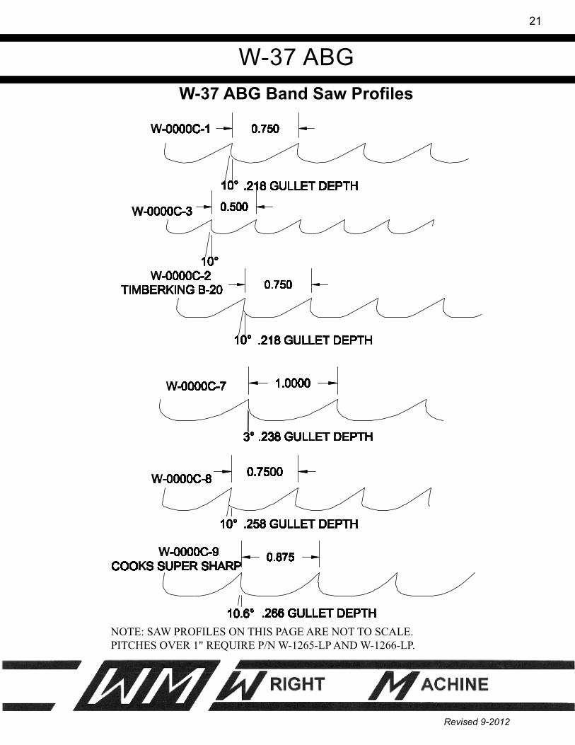
W-37 ABG Band Saw Profiles
NOTE: SAW PROFILES ON THIS PAGE ARE NOT TO SCALE.PITCHES OVER 1" REQUIRE P/N W-1265-LP AND W-1266-LP.

W-37 ABG
22
Revised 9-2012
NOTE: SAW PROFILES ON THIS PAGE ARE NOT TO SCALE.PITCHES OVER 1" REQUIRE P/N W-1265-LP AND W-1266-LP.
W-37 ABG Band Saw Profiles
W-37 ABG
23
Revised 9-2012
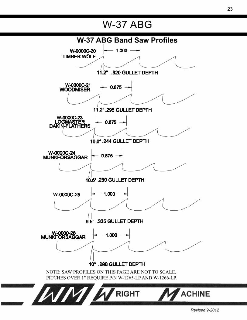
NOTE: SAW PROFILES ON THIS PAGE ARE NOT TO SCALE.PITCHES OVER 1" REQUIRE P/N W-1265-LP AND W-1266-LP.
W-37 ABG Band Saw Profiles

W-37 ABG
24
Revised 9-2012
NOTE: SAW PROFILES ON THIS PAGE ARE NOT TO SCALE.PITCHES OVER 1" REQUIRE P/N W-1265-LP AND W-1266-LP.
W-37 ABG Band Saw Profiles

W-37 ABG
25
Revised 9-2012
ELECTRICAL SCHEMATIC
115VPLUG
WIRE NUT
WIRE NUT
W-517
SWITCHW-193
BLK
BLK
ORNBRN
WHT
BLUWHT
W-520
GRN
SPINDLE MOTOR

W-37 ABG
26
Revised 9-2012
2 POLE SWITCH
GREEN FROM CORDTO GROUND
BLACK FROM CORD
WHITE FROM CORD
W-1291GEAR MOTOR

W-37 ABG
27
Revised 9-2012
INDEXSymbols2 POLE SWITCH 24
AAIR REQUIREMENTS 3Assembly 6
BBAND GUIDE BAR ASSEMBLY 9
Ccam 6CAM MOTOR 3CLAMP / INDEX AREA 12, 14CLAMP PIVOT 15COMMON REPLACEMENT PARTS 5CRATE SIZE 3
Eear protection 2ELECTRICAL SCHEMATIC 22eye protection 2
FFeatures 4Feed Finger 5Finger Arm 5Finger Arm Pivot Bearing 5Finger Arm Spring 5FIXED CLAMP JAW 16Fixed Clamp Jaw 5
GGENERAL SAFETY RULES 2GRINDING WHEEL ADJUSTMENT 10GRINDING WHEELS 5grinding wheels 2

W-37 ABG
28
Revised 9-2012
IndexHHEAD ACTUATOR 18HOOK ANGLE 3
IINDEX PAW 17
LLarge Bore Option 5Large Saw Option 5LIMITED WARRANTY 1
MMAINTENANCE 10MOUNTING GRINDING WHEELS 5MOVABLE CLAMP JAW 16Movable Clamp Jaw 5
OOPERATION 7OPTIONAL SAW SIZE 3OPTIONAL VOLTAGE 3OPTIONS 5
Pprecautions 2PRE SET UP 5PRIMARY INDEX ARM 19
RR.P.M. 3, 6Ramp Follower 5
SSAFETY 2SHIPPING WEIGHT 3SPECIFICATIONS 3SPINDLE MOTOR 3STANDARD SAW SIZE 3STANDARD VOLTAGE 3

W-37 ABG
29
Revised 9-2012
IndexTTECHNICAL 4Topping Wheel 5TROUBLE SHOOTING 10
VVOLTAGE 3
WWARRANTY 1Wheels 2