Embed Size (px)
Citation preview
EN
7.7
22.3
/08.
17
1
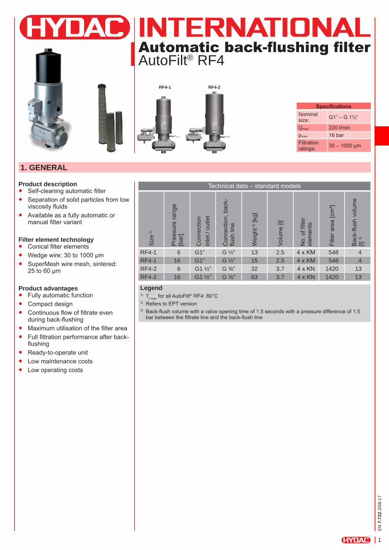
Automatic back-flushing filter AutoFilt® RF4
Product description ● Self-cleaning automatic filter ● Separation of solid particles from low
viscosity fluids ● Available as a fully automatic or
manual filter variant
Filter element technology ● Conical filter elements ● Wedge wire: 30 to 1000 µm ● SuperMesh wire mesh, sintered:
25 to 60 µm
Product advantages ● Fully automatic function ● Compact design ● Continuous flow of filtrate even
during back-flushing ● Maximum utilisation of the filter area ● Full filtration performance after back-
flushing ● Ready-to-operate unit ● Low maintenance costs ● Low operating costs
1. GENERAL
Technical data – standard models
Siz
e 1)
Pre
ssur
e ra
nge
[bar
]
Con
nect
ion
Inle
t / o
utle
t
Con
nect
ion,
bac
k-flu
sh li
ne
Wei
ght 2
) [kg
]
Volu
me
[l]
No.
of fi
lter
elem
ents
Filte
r are
a [c
m²]
Bac
k-flu
sh v
olum
e [l]
3)
RF4-1 6 G1” G ½” 13 2.5 4 x KM 548 4RF4-1 16 G1” G ½” 15 2.5 4 x KM 548 4RF4-2 6 G1 ½” G ¾” 32 3.7 4 x KN 1420 13RF4-2 16 G1 ½” G ¾” 63 3.7 4 x KN 1420 13
Legend1) Ts max for all AutoFilt® RF4: 80°C2) Refers to EPT version3) Back-flush volume with a valve opening time of 1.5 seconds with a pressure difference of 1.5
bar between the filtrate line and the back-flush line
SpecificationsNominal size: G1” – G 1½”
Qmax: 220 l/minpmax: 16 barFiltration ratings: 30 – 1000 µm
RF4-1 RF4-2
EN
7.7
22.3
/08.
17
2
2. FUNCTION
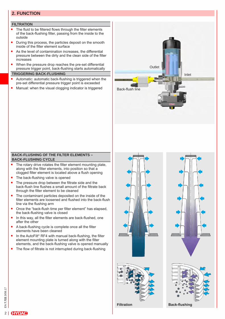
FILTRATION ● The fluid to be filtered flows through the filter elements
of the back-flushing filter, passing from the inside to the outside
● During this process, the particles deposit on the smooth inside of the filter element surface
● As the level of contamination increases, the differential pressure between the dirty and the clean side of the filter increases
● When the pressure drop reaches the pre-set differential pressure trigger point, back-flushing starts automatically
BACK-FLUSHING OF THE FILTER ELEMENTS – BACK-FLUSHING CYCLE ● The rotary drive rotates the filter element mounting plate,
along with the filter elements, into position so that a clogged filter element is located above a flush opening
● The back-flushing valve is opened ● The pressure drop between the filtrate side and the
back-flush line flushes a small amount of the filtrate back through the filter element to be cleaned
● The contaminant particles deposited on the inside of the filter elements are loosened and flushed into the back-flush line via the flushing arm
● Once the “back-flush time per filter element” has elapsed, the back-flushing valve is closed
● In this way, all the filter elements are back-flushed, one after the other
● A back-flushing cycle is complete once all the filter elements have been cleaned
● In the AutoFilt® RF4 with manual back-flushing, the filter element mounting plate is turned along with the filter elements, and the back-flushing valve is opened manually
● The flow of filtrate is not interrupted during back-flushing
TRIGGERING BACK-FLUSHING ● Automatic: automatic back-flushing is triggered when the
pre-set differential pressure trigger point is exceeded ● Manual: when the visual clogging indicator is triggered
Filtration Back-flushing
Outlet
Back-flush line
Inlet
EN
7.7
22.3
/08.
17
3
3. SPECIAL FEATURES
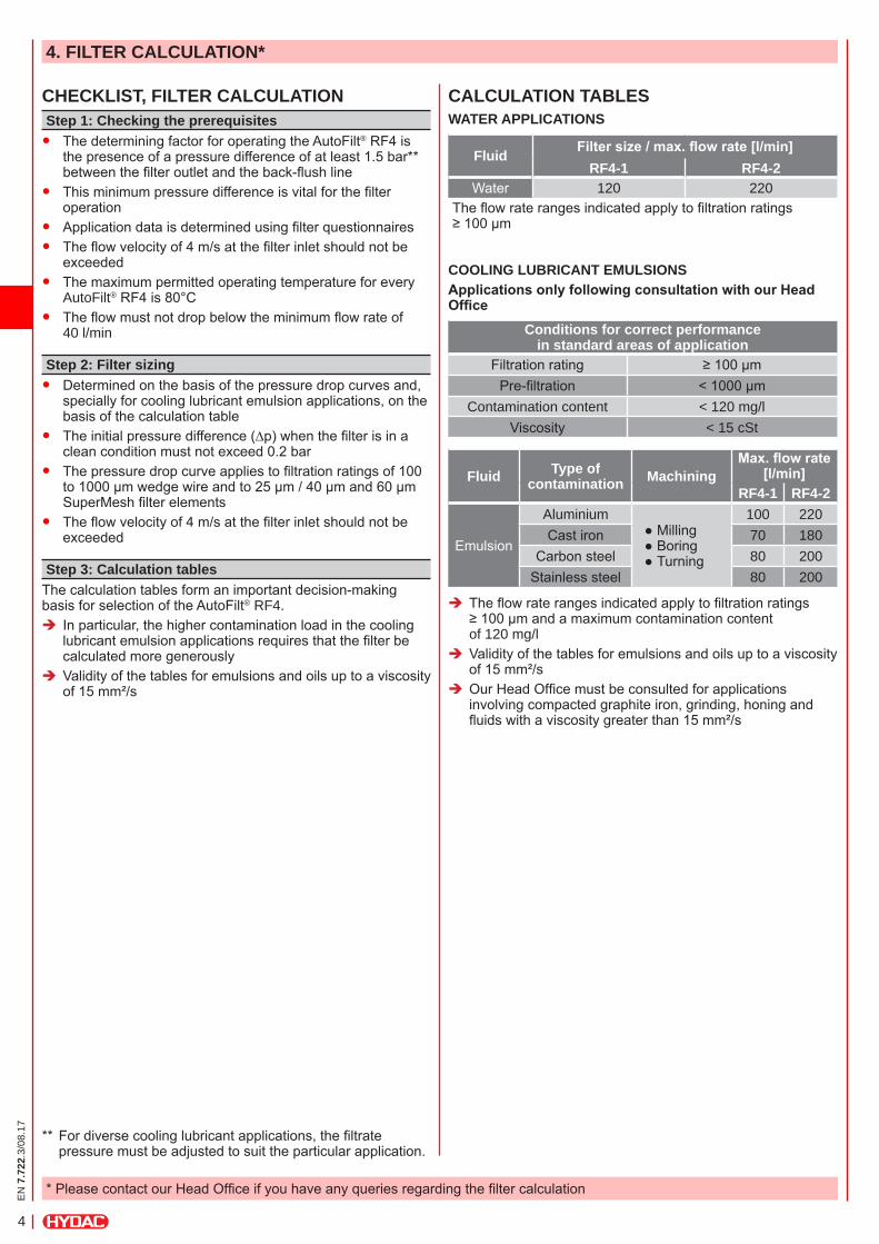
FILTER ELEMENT TECHNOLOGYConical filter elementsRobust wedge wire or SuperMesh filter elements made from stainless steel are used in the HYDAC AutoFilt® RF4 automatic back-flushing filter. The conical shape of the filter elements provides maximum efficiency during filtration and optimum effectiveness during back-flushing.SuperFlush non-stick coatingFor waste-water treatment applications, the filter elements can also be given a special non-stick coating (SuperFlush).Advantages of the SuperFlush coating:
● Unique coating technology ● Available for conical filter elements ● Prevents particle build-up on the filter element surface ● Gel-like particles do not adhere to the filter element surface ● Reduces biofouling ● Increases the service life ● Increases effectiveness
Wedge wire SuperMesh –Wire mesh, sintered, with or without support structure
With WithoutSuperFlush
Non-stick coating for filter elements
Efficiency of back-flushing
Filter elements: cylindrical vs. conical
low high
ISOKINETIC FILTRATION AND BACK-FLUSHINGThe conical shape and alignment of the filter elementsallow uniform flow, resulting in a low pressure drop and effective cleaning of the filter elements.Advantages:
● Fewer back-flushing cycles ● Lower back-flushing losses
PULSE-AIDED BACK-FLUSHINGIn the EPT control types, the filter element to be back-flushed remains in the flushing position for only a few seconds. Rapid opening of the back-flushing valve generates a pressure surge in the filter element openings, providing an additional cleaning effect to the back-flushing process.
SMALL BACK-FLUSH VOLUMES DUE TO CYCLIC CONTROL
In the EPT control types, the back-flushing valve opens and closes during back-flushing of each filter element.
EN
7.7
22.3
/08.
17
4
4. FILTER CALCULATION*
* Please contact our Head Office if you have any queries regarding the filter calculation
CHECKLIST, FILTER CALCULATIONStep 1: Checking the prerequisites ● The determining factor for operating the AutoFilt® RF4 is
the presence of a pressure difference of at least 1.5 bar** between the filter outlet and the back-flush line
● This minimum pressure difference is vital for the filter operation
● Application data is determined using filter questionnaires ● The flow velocity of 4 m/s at the filter inlet should not be
exceeded ● The maximum permitted operating temperature for every
AutoFilt® RF4 is 80°C ● The flow must not drop below the minimum flow rate of
40 l/min
Step 2: Filter sizing ● Determined on the basis of the pressure drop curves and,
specially for cooling lubricant emulsion applications, on the basis of the calculation table
● The initial pressure difference (∆p) when the filter is in a clean condition must not exceed 0.2 bar
● The pressure drop curve applies to filtration ratings of 100 to 1000 µm wedge wire and to 25 µm / 40 µm and 60 µm SuperMesh filter elements
● The flow velocity of 4 m/s at the filter inlet should not be exceeded
Step 3: Calculation tablesThe calculation tables form an important decision-making basis for selection of the AutoFilt® RF4.
Î In particular, the higher contamination load in the cooling lubricant emulsion applications requires that the filter be calculated more generously
Î Validity of the tables for emulsions and oils up to a viscosity of 15 mm²/s
CALCULATION TABLESWATER APPLICATIONS
Fluid Filter size / max. flow rate [l/min]RF4-1 RF4-2
Water 120 220The flow rate ranges indicated apply to filtration ratings ≥ 100 µm
COOLING LUBRICANT EMULSIONSApplications only following consultation with our Head Office
Conditions for correct performance in standard areas of application
Filtration rating ≥ 100 µmPre-filtration < 1000 µm
Contamination content < 120 mg/lViscosity < 15 cSt
Fluid Type of contamination Machining
Max. flow rate [l/min]
RF4-1 RF4-2
Emulsion
Aluminium ● Milling ● Boring ● Turning
100 220Cast iron 70 180
Carbon steel 80 200Stainless steel 80 200
Î The flow rate ranges indicated apply to filtration ratings ≥ 100 µm and a maximum contamination content of 120 mg/l
Î Validity of the tables for emulsions and oils up to a viscosity of 15 mm²/s
Î Our Head Office must be consulted for applications involving compacted graphite iron, grinding, honing and fluids with a viscosity greater than 15 mm²/s
** For diverse cooling lubricant applications, the filtrate pressure must be adjusted to suit the particular application.
EN
7.7
22.3
/08.
17
5
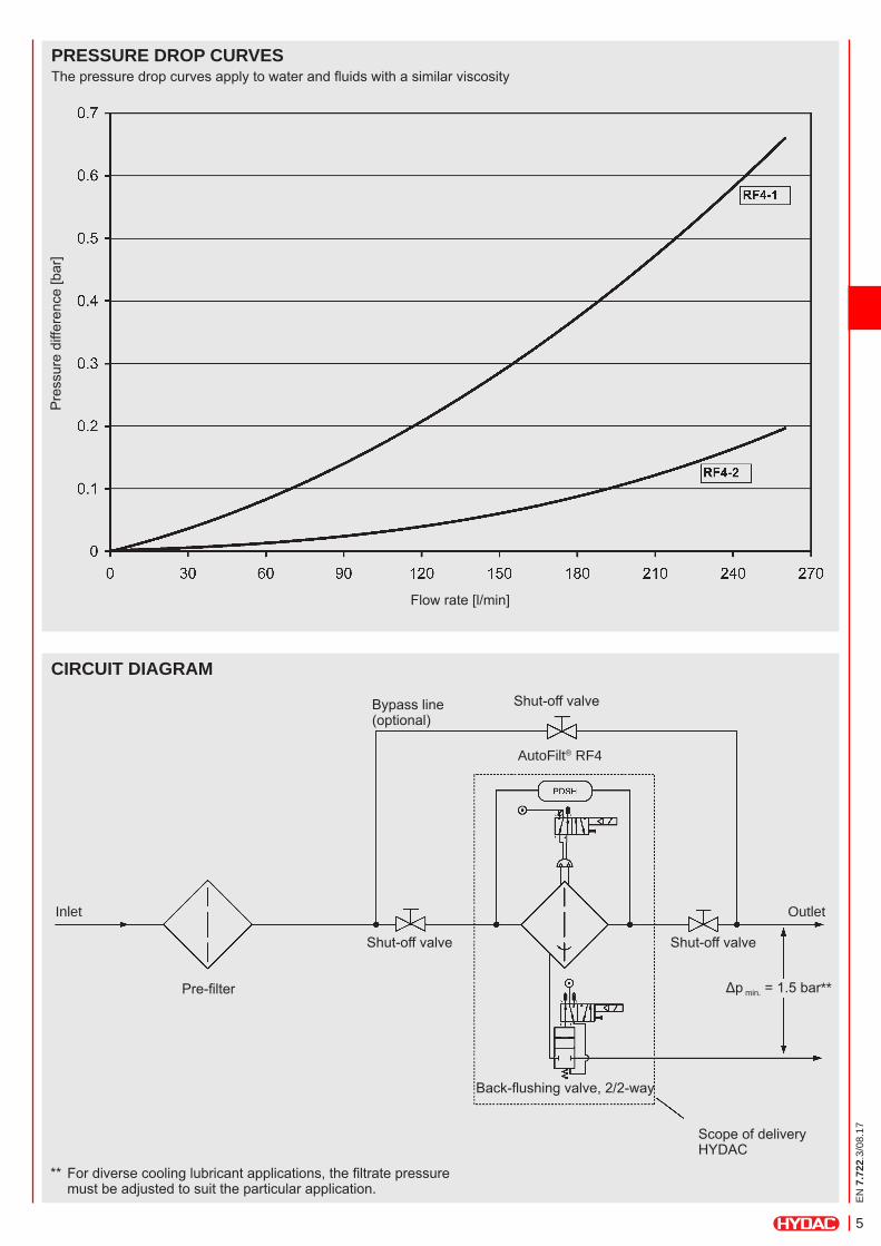
PRESSURE DROP CURVESThe pressure drop curves apply to water and fluids with a similar viscosity
CIRCUIT DIAGRAM
Shut-off valveBypass line (optional)
AutoFilt® RF4
Inlet Outlet
Shut-off valve
Pre-filter
Shut-off valve
Δp min. = 1.5 bar**
Back-flushing valve, 2/2-way
Scope of delivery HYDAC
Pre
ssur
e di
ffere
nce
[bar
]
Flow rate [l/min]
** For diverse cooling lubricant applications, the filtrate pressure must be adjusted to suit the particular application.
EN
7.7
22.3
/08.
17
6
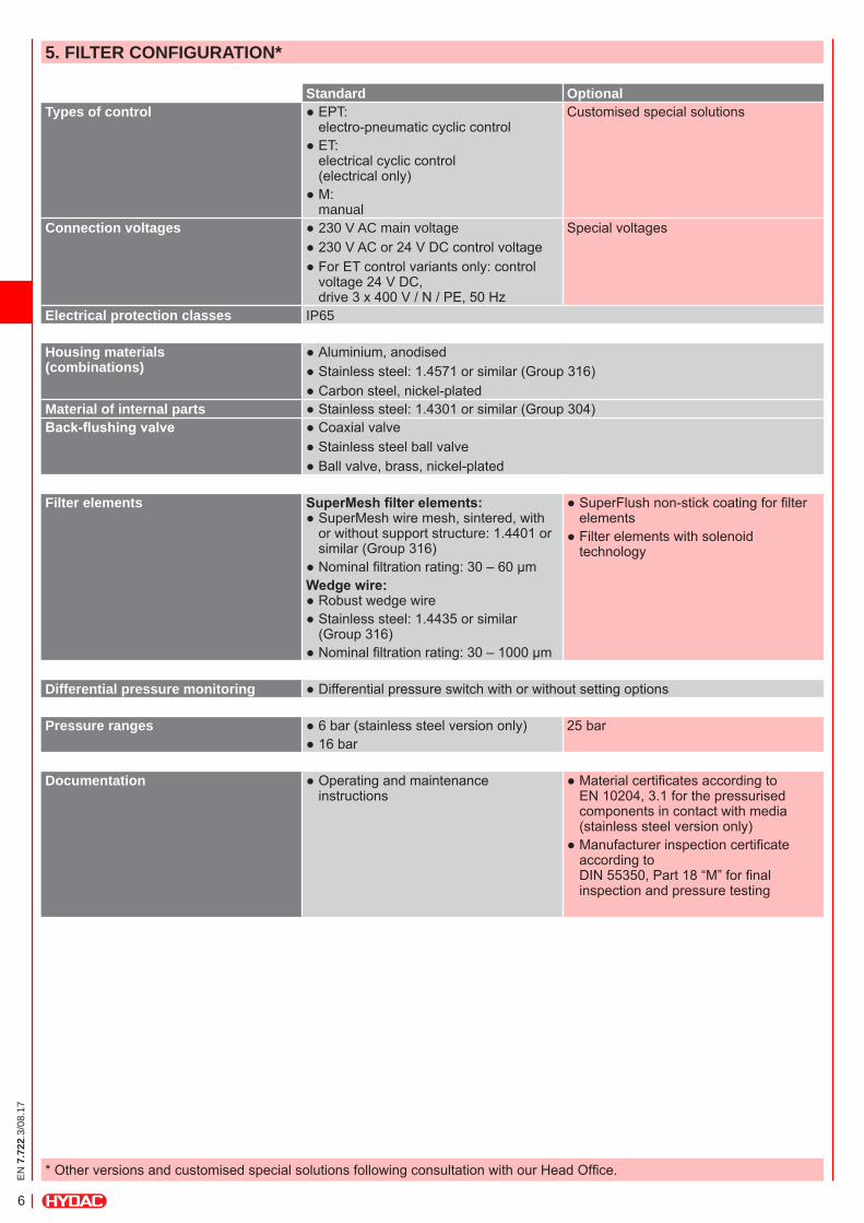
* Other versions and customised special solutions following consultation with our Head Office.
5. FILTER CONFIGURATION*
Standard OptionalTypes of control ● EPT:
electro-pneumatic cyclic control ● ET: electrical cyclic control (electrical only)
● M: manual
Customised special solutions
Connection voltages ● 230 V AC main voltage ● 230 V AC or 24 V DC control voltage ● For ET control variants only: control voltage 24 V DC, drive 3 x 400 V / N / PE, 50 Hz
Special voltages
Electrical protection classes IP65
Housing materials (combinations)
● Aluminium, anodised ● Stainless steel: 1.4571 or similar (Group 316) ● Carbon steel, nickel-plated
Material of internal parts ● Stainless steel: 1.4301 or similar (Group 304)Back-flushing valve ● Coaxial valve
● Stainless steel ball valve ● Ball valve, brass, nickel-plated
Filter elements SuperMesh filter elements: ● SuperMesh wire mesh, sintered, with or without support structure: 1.4401 or similar (Group 316)
● Nominal filtration rating: 30 – 60 µmWedge wire:
● Robust wedge wire ● Stainless steel: 1.4435 or similar (Group 316)
● Nominal filtration rating: 30 – 1000 µm
● SuperFlush non-stick coating for filter elements
● Filter elements with solenoid technology
Differential pressure monitoring ● Differential pressure switch with or without setting options
Pressure ranges ● 6 bar (stainless steel version only) ● 16 bar
25 bar
Documentation ● Operating and maintenance instructions
● Material certificates according to EN 10204, 3.1 for the pressurised components in contact with media (stainless steel version only)
● Manufacturer inspection certificate according to DIN 55350, Part 18 “M” for final inspection and pressure testing
EN
7.7
22.3
/08.
17
7
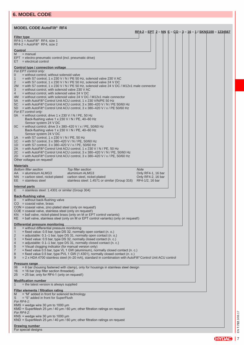
MODEL CODE AutoFilt® RF4RF4-2 – EPT 2 – NN E – CO – 3 – 16 – 1 / SKNS100 – 1234567
Filter type RF4-1 = AutoFilt® RF4, size 1 RF4-2 = AutoFilt® RF4, size 2
Control M = manual EPT = electro-pneumatic control (incl. pneumatic drive) ET = electrical control
Control type / connection voltage For EPT control only: 0 = without control, without solenoid valve 1 = with S7 control, 1 x 230 V / N / PE 50 Hz, solenoid valve 230 V AC 2 = with S7 control, 1 x 230 V / N / PE 50 Hz, solenoid valve 24 V DC 2M = with S7 control, 1 x 230 V / N / PE 50 Hz, solenoid valve 24 V DC / M12x1 male connector 3 = without control, with solenoid valve 230 V AC 4 = without control, with solenoid valve 24 V DC 4M = without control, with solenoid valve 24 V DC / M12x1 male connector 5A = with AutoFilt® Control Unit ACU control, 1 x 230 V/N/PE 50 Hz 5C = with AutoFilt® Control Unit ACU control, 3 x 380–420 V / N / PE 50/60 Hz 5D = with AutoFilt® Control Unit ACU control, 3 x 380–420 V / x / PE 50/60 Hz For ET control only: 0A = without control, drive 1 x 230 V / N / PE, 50 Hz Back-flushingvalve1x230V/N/PE,40–60Hz Sensor system 24 V DC 0C = without control, drive 3 x 380–420 V / x / PE, 50/60 Hz Back-flushingvalve1x230V/N/PE,40–60Hz Sensor system 24 V DC 1A = with S7 control, 1 x 230 V / N / PE, 50 Hz 1C = with S7 control, 3 x 380–420 V / N / PE, 50/60 Hz 1D = with S7 control, 3 x 380–420 V / x / PE, 50/60 Hz 2A = with AutoFilt® Control Unit ACU control, 1 x 230 V / N / PE, 50 Hz 2C = with AutoFilt® Control Unit ACU control, 3 x 380–420 V / N / PE, 50/60 Hz 2D = with AutoFilt® Control Unit ACU control, 3 x 380–420 V / x / PE, 50/60 Hz Othervoltagesonrequest!
Materials Bottom filter section Top filter section Note AA = aluminium ALMG3 aluminium ALMG3 Only RF4-1, 16 bar NN = carbon steel, nickel-plated carbon steel, nickel-plated Only RF4-2, 16 bar EE = stainless steel stainless steel: 1.4571 or similar (Group 316) RF4-1/2, 16 bar
Internal parts E = stainless steel: 1.4301 or similar (Group 304)
Back-flushing valve 0 =withoutback-flushingvalve CO = coaxial valve, brass CON=coaxialvalve,zinc-platedsteel(onlyonrequest!) COE=coaxialvalve,stainlesssteel(onlyonrequest!) KN = ball valve, nickel-plated brass (only on M or EPT control variants) KE =ballvalve,stainlesssteel(onlyonMorEPTcontrolvariants)(onlyonrequest!)
Differential pressure monitoring 0 =withoutdifferentialpressuremonitoring 1 =fixedvalue:0.5bar,typeDS32,normallyopencontact(n.o.) 2 = adjustable: 0.1–1 bar, type DS 31, normally open contact (n. o.) 3 =fixedvalue:0.5bar,typeDS32,normallyclosedcontact(n.c.) 4 = adjustable: 0.1–1 bar, type DS 31, normally closed contact (n. c.) 5 =Visualcloggingindicator(formanualversiononly) 7 =fixedvalue0.5bar,typeVL1GW(aluminium),normallyclosedcontact(n.c.) 8 =fixedvalue0.5bar,typePVL1GW(1.4301),normallyclosedcontact(n.c.) 9 = 2 x HDA 4700 stainless steel (4–20 mA), standard in combination with AutoFilt® Control Unit ACU control
Pressure range 06 =6bar(housingfastenedwithclamp),onlyforhousingsinstainlesssteeldesign 16 =16bar(topfiltersectionthreaded) 25 =25bar,onlyforRF4-1(onlyonrequest!)
Modification number 1 = the latest version is always supplied
Filter elements / filtration rating M =“M”addedinfrontforsolenoidtechnology S = “S” added in front for SuperFlush For RF4-1: KMS=wedgewire30µmto1000µm KMD=SuperMesh25µm/40µm/60µm;otherfiltrationratingsonrequest For RF4-2: KNS =wedgewire30µmto1000µm KND=SuperMesh25µm/40µm/60µm;otherfiltrationratingsonrequest
Drawing number Forspecialdesigns
6. MODEL CODE
EN
7.7
22.3
/08.
17
8
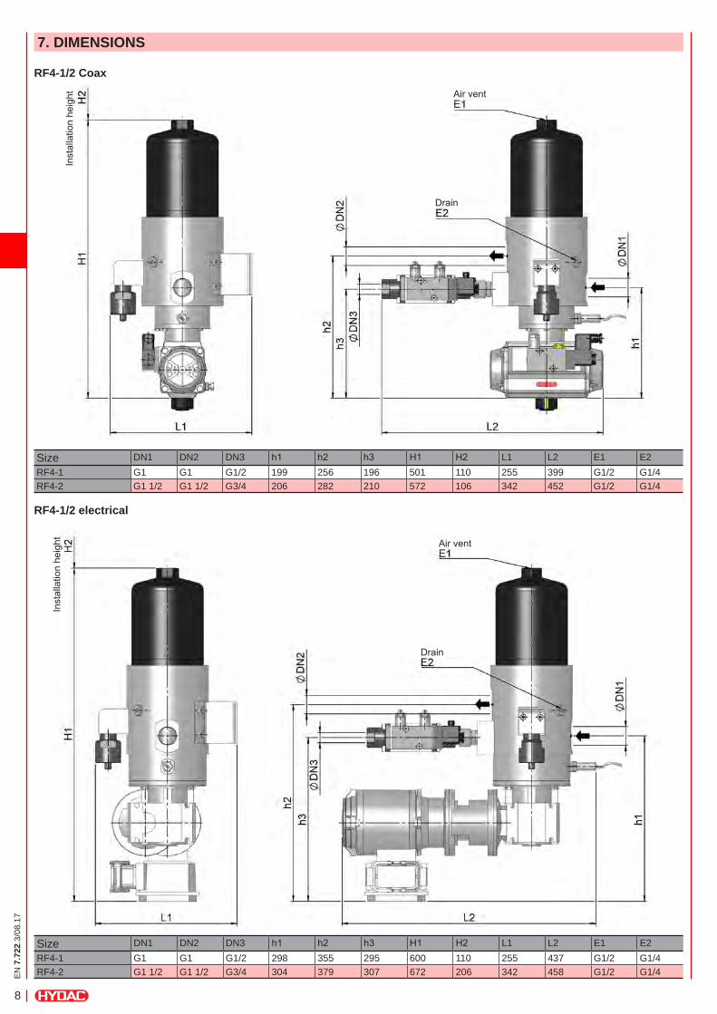
7. DIMENSIONS
RF4-1/2 Coax
RF4-1/2 electrical
Inst
alla
tion
heig
htIn
stal
latio
n he
ight
Air vent
Size DN1 DN2 DN3 h1 h2 h3 H1 H2 L1 L2 E1 E2RF4-1 G1 G1 G1/2 199 256 196 501 110 255 399 G1/2 G1/4RF4-2 G1 1/2 G1 1/2 G3/4 206 282 210 572 106 342 452 G1/2 G1/4
Size DN1 DN2 DN3 h1 h2 h3 H1 H2 L1 L2 E1 E2RF4-1 G1 G1 G1/2 298 355 295 600 110 255 437 G1/2 G1/4RF4-2 G1 1/2 G1 1/2 G3/4 304 379 307 672 206 342 458 G1/2 G1/4
Air vent
Drain
Drain
EN
7.7
22.3
/08.
17
9
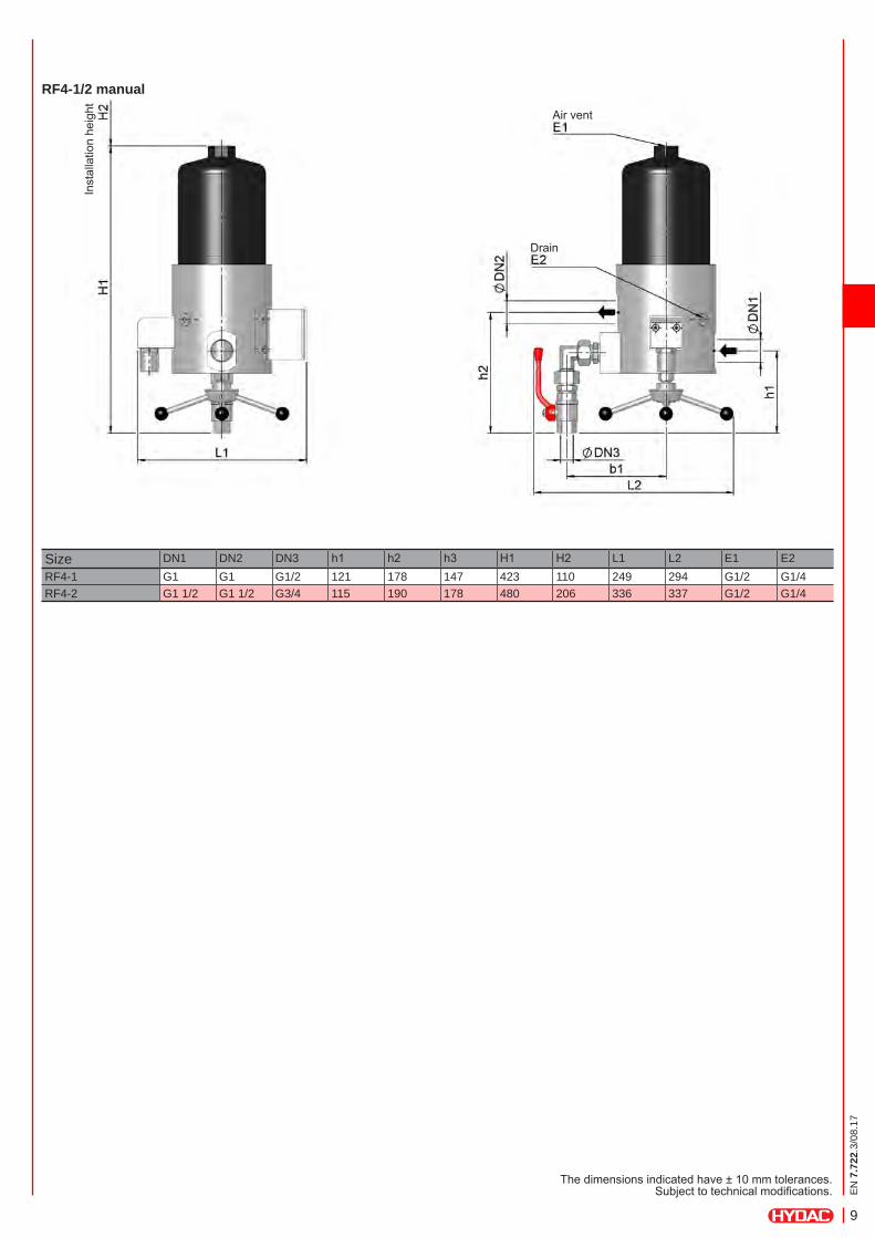
Inst
alla
tion
heig
ht
The dimensions indicated have ± 10 mm tolerances. Subject to technical modifications.
Size DN1 DN2 DN3 h1 h2 h3 H1 H2 L1 L2 E1 E2RF4-1 G1 G1 G1/2 121 178 147 423 110 249 294 G1/2 G1/4RF4-2 G1 1/2 G1 1/2 G3/4 115 190 178 480 206 336 337 G1/2 G1/4
RF4-1/2 manual
Air vent
Drain

EN
7.7
22.3
/08.
17
10
NOTEThe information in this brochure relates to the operating conditions and applications described. For applications and/or operating conditions not described, please contact the relevant technical department. Subject to technical modifications.
Process Technology GmbH Am Wrangelflöz 1 D-66538 Neunkirchen Tel.: +49 (0)6897 - 509-1241 Fax: +49 (0)6897 - 509-1278 Internet: www.hydac.com E-mail: [email protected]