Embed Size (px)
Citation preview

Automatic Air ValvesFor raw and potable water
For domestic and industrial sewage
Technical information for project planners and technicians

2
This page is intentionally left blank.

3
Table of contents Page
1. The purpose of aerating and air release 42. The points of aerating and air release 43. The ways of aerating and air release 53.1 Ways of functioning 53.1.1 Functioning of H-TEC air valve Model 987 (here type 2”): 53.1.2 Functioning of H-TEC air valve Model 986: 54. Types of air valves 64.1 AV Model 987 - Air valve (single orifice / double orifice) 64.2 AV Model 986 - Air valve (with cup seal) 64.3 AVS Model 992 and Model 985 – Air valve set 74.3.1 Description of AVS Model 992 Description of AVS Model 985 (diaphragm) 74.3.2 Installation above and below ground 74.4 Accessories 84.4.1 Surface box for below ground installation of air valve set Model 992 84.4.2 Drainage element for air valve set Model 992 84.4.3 Manhole cover and ring for air valve set Model 985 84.4.4 Indicator plates for air valve 84.4.5 Flushing and water tapping set (for air valve set Model 992) 85. Rating of valve size 95.1 Rating of valve size 95.2 Rating according to the flow performance diagram 106. Installation 116.1 Design of the connection 116.2 Air valves in plants and manholes 116.3 H-TEC air valve set, the logical further development of the air valve 126.4 Shortening of air valve set Model 992 on site 126.5 AVS - installation in existing manholes 126.6 AVS - installation in ground water 126.7 AVS - installation in flood areas 136.8 AVS for waste water in ground water areas 136.9 AV for water treatment plants 136.10 AV for sterilization plants 136.11 AV upstream and AV downstream of control valves 136.12 AV in fire extinguishing systems 146.13 AV upstream and downstream of reductions 146.14 AV on waste water head pipes with automatic aeration 146.15 AV on waste water vacuum pipes 146.16 Insulation 147. Pressure testing 158. Functional testing and maintenance 158.1 Reasons for maintenance 158.2 Maintenance intervals 158.3 Important maintenance work 158.3.1 Maintenance of air valve set Model 992 168.3.2 Maintenance of AVS Model 985 179. Specification 189.1 Air valves 189.2 Air valve sets 199.3 Air valve with stand pipe base 199.4 Accessories 2010. Safety hints 2011. References 20

4
2. The points of aerating and air release
The Air Valve Releases air from the pipeline: accumulations of air must be expected where the operating pressure is lower than in neighbouring pipeline sections:
a) at each geodesic high point b) at each hydraulic high point c) at long ascending or descending pipe sections (recommended installation in intervals of approx. 0.5 mile/800 m) d) downstream of pumps and upstream of throttling points
The Air Valve admits the required amount of air: at each spot of the pipeline where negative pressure must be expected, such as:
e) downstream of quick-acting valves (pipe fracture safety valves PFSV)
1. The purpose of aerating and air release
A water transport system is to be kept in an operating condition as stable as possible by taking the appropriate measures.
Inclusions of air may have considerable negative effects on a pipeline system, such as:
- longer running time pumps - higher energy input, shorter lifecycle of pumps - pressure fluctuations - reduction of flow - water hammer - pipe breakage - dry running of pumps
The possibility of air entering into a pipeline system cannot be eliminated entirely. Already the air dissolved in the water proper may turn gaseous under certain pressure and temperature conditions. Even larger quan- tities of air will get into the pipeline system during maintenance work. These amounts of air will collect at cer- tain points from where they have to be carried off by means of the appropriate valves (see below illustration).
On the other hand, the lack of air may also lead to failures. Negative pressure will be created when wa- ter flows off too fast. This is mostly the case when pipes get drained or when pipe fractures occur, as well as in case of pumps being disconnected or downstream of quick-acting valves such as pipe fracture safety val- ves, where the flow of water is stopped abruptly, thus creating a negative pressure between the valve and the head of water being discharged. In this case sufficient air must be admitted to the pipeline through the air val- ve to limit the negative pressure and prevent damage to the pipeline.
Moreover, there are accumulations of gas in waste water because of processes of decay and because of the deliberate blowing in of air.
This implies the following requirements on air valves:
- releasing minor amounts of air under operating pressure - releasing major amounts of air - admitting major amounts of air
b
RBS
ea b
cd
c
c
a b

5
3. The ways of aerating and air release
large cross sectionA = 1.488 in2
small cross sectionA = 0.003 in2
3.1.2 Functioning of H-TEC air valve Model 986:
(This valve is also installed in air valve set Model 985)
Medium: potable water and waste water
Releasing minor amounts of air:During operation of a pipe-line releasing is effected via the small cross section.
Aerating:During draining of a pipeline aeration is effected via the large cross section.
Closing: After venting the valve closes auto-matically.
Releasing major amounts of air:During filling a pipeline re-leasing is effected via the large cross section.
Releasing minor amounts of air:During operation of a pipe-line the venting cross sec-tion will be opened as far as necessary.
Aerating:During draining of a pipeline aeration is effected via the who-le aeration cross sec-tion.
Closing: After venting the val-ve closes automati-cally.
Releasing major amounts of air:For filling a pipeline the whole venting cross section is available.
3.1.1 Functioning of H-TEC air valve Model 987 (here type 2”):
Medium: potable water
3.1 Ways of functioning
A = 0.744 in2 A = 0 ..... 0.744 in2

6
• Improved air intake and release capacity• Very high air release during operation continuously variable from 0 to 250 psi / 16 bar• High-grade materials• Easy maintenance• Excellent UV resistance• Only for air release or air intake - on request• 350 psi / PN 25 - on request
HaVent®, the new performance generation
Air release capacity during pipeline filling
The air release capacity is 106.000 gal/h even at a dif-ferential pressure of 1.45 psi / 0,1 bar
Air release during operation The air release capacity over 26.500 gal/h even at a differential pressure of 29 psi / 2 bar
Aeration of pipeline
The air intake capacity is approx. 79.500 gal/h at a negative pressure of -1.45 psi / -0,1 bar
Possible connections
• Female thread 2“• Male thread 2“• Flange 4“• Flange other nominal width on request!
Air
rel
ease
cap
acit
y Q
(m
3/h
)
Differential pressure (bar) Differential pressure (bar)
Negative pressure (bar)
Air
rel
ease
cap
acit
y Q
(m
3/h
)A
ir in
take
cap
acit
y (m
3/h
)
Ventilation on highest level for water pipelines

7
Large outlet cross section for maximum air release and intake capacity during pipeline filling or drainingA = 2.3 in2
Large air release cross section for reliable air release during operationAmax. = 0.3 in2
High-grade enclosure of aluminium
Robust float of foamed plastics
Flow control for optimized closing
Valve mechanism
• No loose components
• Can be taken out in one piece
• Easy cleaning
• Easy exchange of wear parts if required
Technical features

8
NPT 2”: for large amounts of air NPT 1”: for small amounts of air
4.1 Model 987 - Air Valve (single orifice / double orifice)
Materials: Body POM Seat CuZn35Pb3AsFloat POMValve gasket EPDMUV cap PEInsect protective grid ss316
Technical data: NP 2” NP 1”
Test pressure (body) body 350 psi / 24 bar body 350 psi / 24 bar
Operating pressure standard: 14.5-250 psi / 0,8 - 17.2 bar standard: 11.6 - 250 psi alternative: 1.5 - 87 psi alternative: 1.5 - 87 psi
Opening cross section 1.448 in2 / 0.003 in2 0.003 in2
Max. air release capacity 50.190 gal/h 2.377 gal/h
Connection female thread 2” or flange female thread 1”
Insect protective grid yes no
Weight 5.1 lbs / 2,35 kg 1.65 lbs / 0.75 kg
4.2 Model 986 - Air Valve (with cup seal)
Materials:
Body fluidized bed epoxy powder coated alternatively SS 316
Body nut with screen POM / 1.4301
Float POM
Valve body - bonnet POM
O-ring 160 x 6 NBR
Outlet elbow with strainer PE 100 / SS 316
Technical data:
Test pressure (body) body 350 psi / 24 bar
Operating range 0 -250 psi / 0 – 16 bar
Opening cross section 0.75 in2 / 480 mm2
Max. air release capacity 230 m3/h / 60.760 gal/h
Connection female thread 2” or Flange 2“ - 8“
other flanges on request
Media raw and potable water domestic and industrial waste water
Large amounts of air
can be released under
operating pressure
due to infinitely
variable operation!
4. Types of Air Valves
Features:
infinitely variable
operation from 0 bar onward
seat not in contact with the medium
suitable for parallel operation
large orifice= prevents contamination
= high air release capacity even under operating pressure
On request: valve with ventilate-function only

9
4.3.1 Description of Air Valve Set, Model 992 Medium: potable water
stand pipe of stainless steel replaces the chamber and permits easy main-tenance of the air valve
H-TEC 2” – air valve
high-grade materials such as POM for the body, bronze for the seats and EPDM for sealings ensure corrosion resistance and permanent function (maintenance see item 6.)
drain-off fitting
hood with air vent slots
automatic shut-off function via initial spring tension ensures sealing even at 0 psi
insect protective grid
additional elongated holes permit shortening by 100 mm
Description of Air Valve Set Model 985 (diaphragm) Medium: potable water and waste water
Above ground(PCD)
2.5 ft / 0,75 m3.3 ft / 1,00 m4.1 ft / 1,25 m4.9 ft / 1,50 m
L Spigot end
2.7 ft / 815 mm3.7 ft / 1115 mm4.5 ft / 1365 mm5.3 ft / 1615 mm
L Flange
2.5 ft / 755 mm3,5 ft / 1055 mm4.3 ft / 1305 mm5.1 ft / 1555 mm
Below ground(PCD)
3.3 ft / 1,00 m4.1 ft / 1,25 m4.9 ft / 1,50 m5.7 ft / 1,75 m
Pipe cover depth:
4.3.2 Installation above and below ground
An Air Valve Set can be installed both above ground and below ground. The above ground type will be used wherever the valve shall be installed in open terrain.
above ground below ground
air valve
cover
chamber cylinder
operating rod
shut-off facility with blank of stainless steel
BAIO® spigot end 3“ or flange 3“
drain-off fitting (optional: can be closed via end fitting)
Both Air Valve Sets are available with flange 3 or BAIO® spigot end. When using a BAIO® spigot end please apply a dirt cover and locking ring (see specification of accessories).
4.3 Model 992 and Model 985 – Air Valve Set
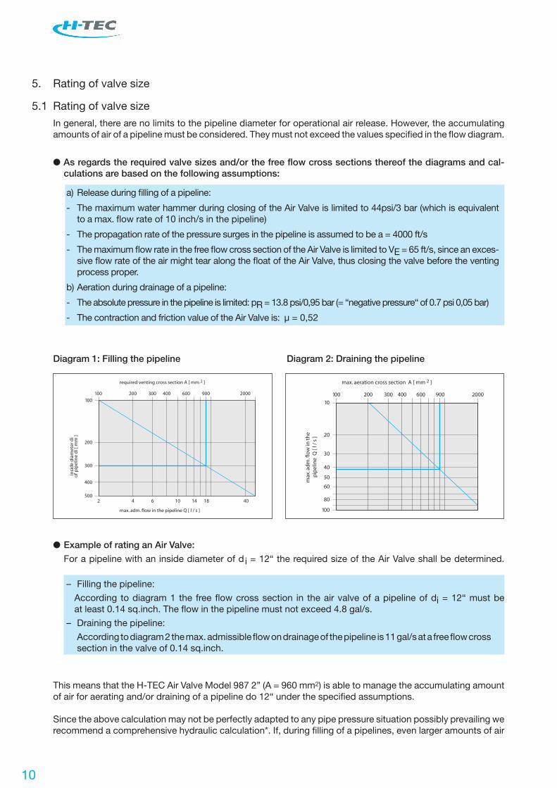
Diagram 1: Filling the pipeline
200
insi
de
dia
met
er d
io
f pip
elin
e d
i [ m
m ]
100 300 400 600 900 2000100
200
300
400
50042 6 10 14 18 40
required venting cross section A [ mm 2 ]
max. adm. flow in the pipeline Q [ l / s ]
Diagram 2: Draining the pipeline
Example of rating an Air Valve:
For a pipeline with an inside diameter of di = 12“ the required size of the Air Valve shall be determined.
– Filling the pipeline:
According to diagram 1 the free flow cross section in the air valve of a pipeline of di = 12“ must be at least 0.14 sq.inch. The flow in the pipeline must not exceed 4.8 gal/s.
– Draining the pipeline:
According to diagram 2 the max. admissible flow on drainage of the pipeline is 11 gal/s at a free flow cross section in the valve of 0.14 sq.inch.
This means that the H-TEC Air Valve Model 987 2” (A = 960 mm2) is able to manage the accumulating amount of air for aerating and/or draining of a pipeline do 12“ under the specified assumptions.
Since the above calculation may not be perfectly adapted to any pipe pressure situation possibly prevailing we recommend a comprehensive hydraulic calculation*. If, during filling of a pipelines, even larger amounts of air
5. Rating of valve size
5.1 Rating of valve size
In general, there are no limits to the pipeline diameter for operational air release. However, the accumulating amounts of air of a pipeline must be considered. They must not exceed the values specified in the flow diagram.
As regards the required valve sizes and/or the free flow cross sections thereof the diagrams and cal- culations are based on the following assumptions:
a) Release during filling of a pipeline:
- The maximum water hammer during closing of the Air Valve is limited to 44psi/3 bar (which is equivalent to a max. flow rate of 10 inch/s in the pipeline)
- The propagation rate of the pressure surges in the pipeline is assumed to be a = 4000 ft/s
- The maximum flow rate in the free flow cross section of the Air Valve is limited to VE = 65 ft/s, since an exces- sive flow rate of the air might tear along the float of the Air Valve, thus closing the valve before the venting process proper.
b) Aeration during drainage of a pipeline:
- The absolute pressure in the pipeline is limited: pR = 13.8 psi/0,95 bar (= “negative pressure“ of 0.7 psi 0,05 bar)
- The contraction and friction value of the Air Valve is: µ = 0,52
10

11
5.2 Rating according to the flow performance diagram
The following diagram shows the interrelation between air release and aeration capacity of the valve at a given overpressure / negative pressure in the valve.
Explanation by way of examples:
a) Air release capacity of AV 1” at 73 psi / 5 bar: ≈ 1.590 gal/h
b) Air release capacity of AV 987 – 2” at 0.7 psi / 0,05 bar: ≈ 47.500 gal/h
c) Air release capacity of AV 987 – 2” at 73 psi / 5 bar: ≈ 2.000 gal/h (as the big orifice is closed because of the air flow)
d) Air intake capacity of AV 987 – 2”: ≈ 145.300 gal/h
must be expected, air release may also be performed manually. In this case a flushing and water tapping set is installed in the H-TEC Air Valve Set. However, other air release devices such as hydrants, may be used, too.
12
6. Installation
The points of installation are usually the relative or absolute high points of the pipeline. Because of the regular checks that are necessary they shall be easily accessible and not be situated in highly frequented traffic areas. Ho- wever, the correct place of installation is more important (e.g. high point).
6.1 Design of the connection
The nominal width of the supply line shall be as large as possible and should be equivalent to at least the val- ve size. This pipeline should run vertical from the pipeline to the valve. The dimension of the upstream shut-off valve, too, should be equivalent to at least the valve size. The largely dimensioned supply line to the valve ser- ves the purpose of collecting the air carried along with the water from the main line at this point to be then discharged by the valve.
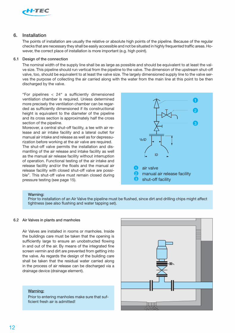
“For pipelines < 24“ a sufficiently dimensioned ventilation chamber is required. Unless determined more precisely the ventilation chamber can be regar-ded as sufficiently dimensioned if its constructional height is equivalent to the diameter of the pipeline and its cross section is approximately half the cross section of the pipeline.Moreover, a central shut-off facility, a tee with air re-lease and air intake facility and a lateral outlet for manual air intake and release as well as for depressu-rization before working at the air valve are required.The shut-off valve permits the installation and dis-mantling of the air release and intake facility as well as the manual air release facility without interruption of operation. Functional testing of the air intake and release facility and/or the floats and the manual air release facility with closed shut-off valve are possi-ble”. This shut-off valve must remain closed during pressure testing (see page 15).
Warning:Prior to installation of an Air Valve the pipeline must be flushed, since dirt and drilling chips might affect tightness (see also flushing and water tapping set).
air valvemanual air release facilityshut-off facility
2
3
1
2
3
Air Valves are installed in rooms or manholes. Inside the buildings care must be taken that the opening is sufficiently large to ensure an unobstructed flowing in and out of the air. By means of the integrated fine screen vermin and dirt are prevented from getting into the valve. As regards the design of the building care shall be taken that the residual water carried along in the process of air release can be discharged via a drainage device (drainage element).
6.2 Air Valves in plants and manholes
Warning:
Prior to entering manholes make sure that suf-ficient fresh air is admitted!
1

13
Conventional manhole H-TEC Air Valve Set
6.3 H-TEC Air Valve Set, the logical further development of the air valve
Advantages of H-TEC air valve set:
– low costs – no access of manhole required – integrated shut-off element – maintenance work easy and time-saving
No danger because of access to manhole!
6.4 Shortening of Air Valve Set Model. 992 on site
Both the above ground and the below ground version of the Air Valve Set may require shortening on site be- cause of unexpected changes of the pipe cover depth. According to the drawing the operating tube (with the marking) and the stand pipe of stainless steel are cut by 4“. Make sure to produce a straight cut edge.
6.5 Installation in existing manholes
Air Valve Sets can also be installed in existing manholes. They are mounted on the pipeline instead of the old air valve. The manhole is backfilled with bulk material, thus avoiding future maintenance of the manhole. Moreover, the valve can be installed and dismantled from above for testing and maintenance.
bulkmaterial

14
6.6 Installation in ground water
If rising ground water exceeds the level of the drain- off fitting dirty water may be sucked into the pipeline during aeration. The drain-off fitting must be closed or a back flow preventer must be installed. (This is not included in the standard scope of supply and must be ordered separately). In both cases it must be en- sured by regular inspection of the Air Valve Set that no groundor rain water can accumulate in the Air Valve Set. If required,the water must be pumped out by means of a handpump.
Warning: Penetrating ground or rain water may be sucked into the pipeline in case of negative pressure. Contamination and germs may be carried in.
6.7 Installation in flood areas
In flood areas the length of the AVS shall be rated such that the hood with the air vent slots is approx 1.5 ft above the water level to be expected to prevent any dirty water from penetrating the Air Valve Set.
The drain-off fitting must be closed. (This is not in- cluded in the standard scope of supply and must be prepared on site).
Warning: Penetrating ground or rain water may be sucked into the pipeline in case of negative pressure. Contamination and germs may be carried in.
6.8 For waste water in ground water areas
The drain-off fitting must be closed, e.g. by means of a pipe and end fitting, to prevent waste water from emerging into the soil.
15
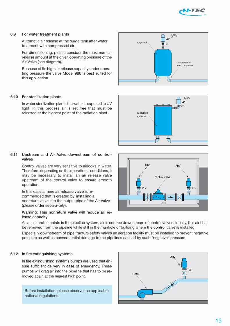
6.9 For water treatment plants
Automatic air release at the surge tank after water treatment with compressed air.
For dimensioning, please consider the maximum air release amount at the given operating pressure of the Air Valve (see diagram).
Because of its high air release capacity under opera- ting pressure the valve Model 986 is best suited for this application.
surge tank
compressed airfrom compressor
6.10 For sterilization plants
In water sterilization plants the water is exposed to UV light. In this process air is set free that must be released at the highest point of the radiation plant. radiation
cylinder
6.11 Upstream and Air Valve downstream of control- valves
Control valves are very sensitive to airlocks in water. Therefore, depending on the operational conditions, it may be necessary to install an air release valve upstream of the control valve to ensure smooth operation.
In this case a mere air release valve is re- commended that is created by installing a nonreturn valve into the output pipe of the Air Valve (please order separa-tely).
Warning: This nonreturn valve will reduce air re- lease capacity!
As at all throttle points in the pipeline system, air is set free downstream of control valves. Ideally, this air shall be removed from the pipeline while still in the manhole or building where the control valve is installed.
Especially downstream of pipe fracture safety valves an aeration facility must be installed to prevent negative pressure as well as consequential damage to the pipelines caused by such “negative” pressure.
6.12 In fire extinguishing systems
In fire extinguishing systems pumps are used that en- sure sufficient delivery in case of emergency. These pumps will drag air into the pipeline that has to be re- moved again at the nearest high point.
Before installation, please observe the applicable national regulations.
ARV
ARV
16
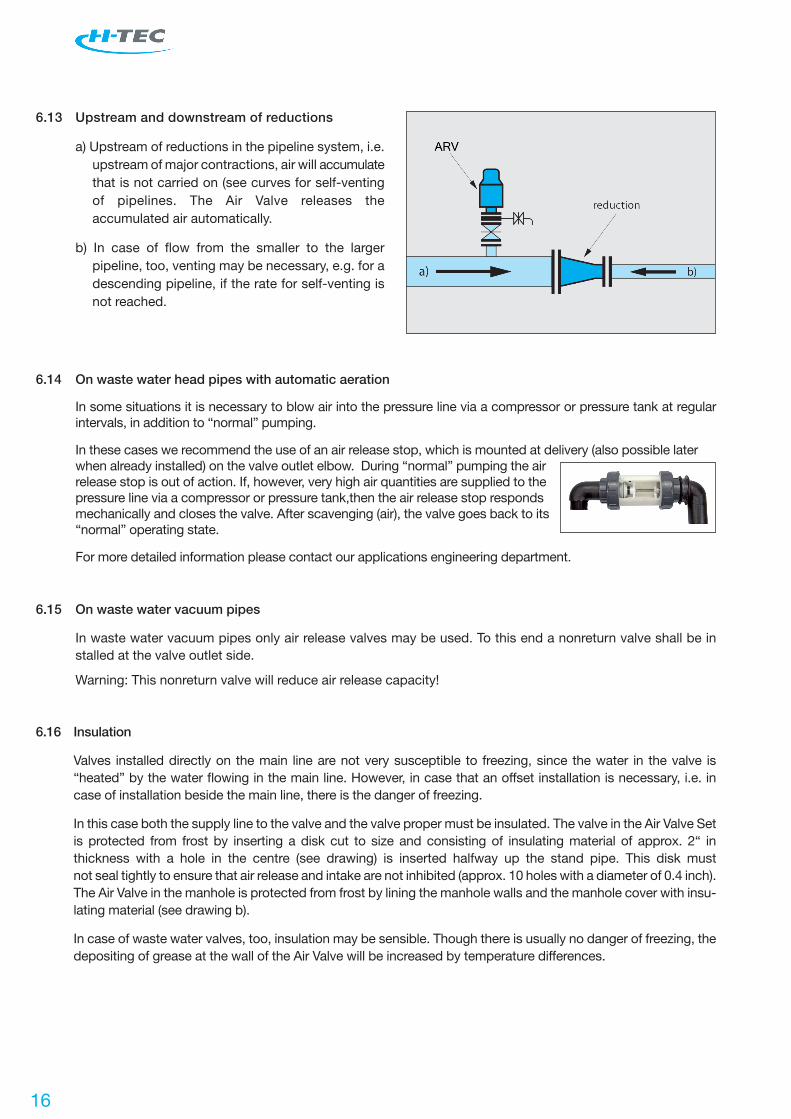
6.13 Upstream and downstream of reductions
a) Upstream of reductions in the pipeline system, i.e. upstream of major contractions, air will accumulate that is not carried on (see curves for self-venting of pipelines. The Air Valve releases the accumulated air automatically.
b) In case of flow from the smaller to the larger pipeline, too, venting may be necessary, e.g. for a descending pipeline, if the rate for self-venting is not reached.
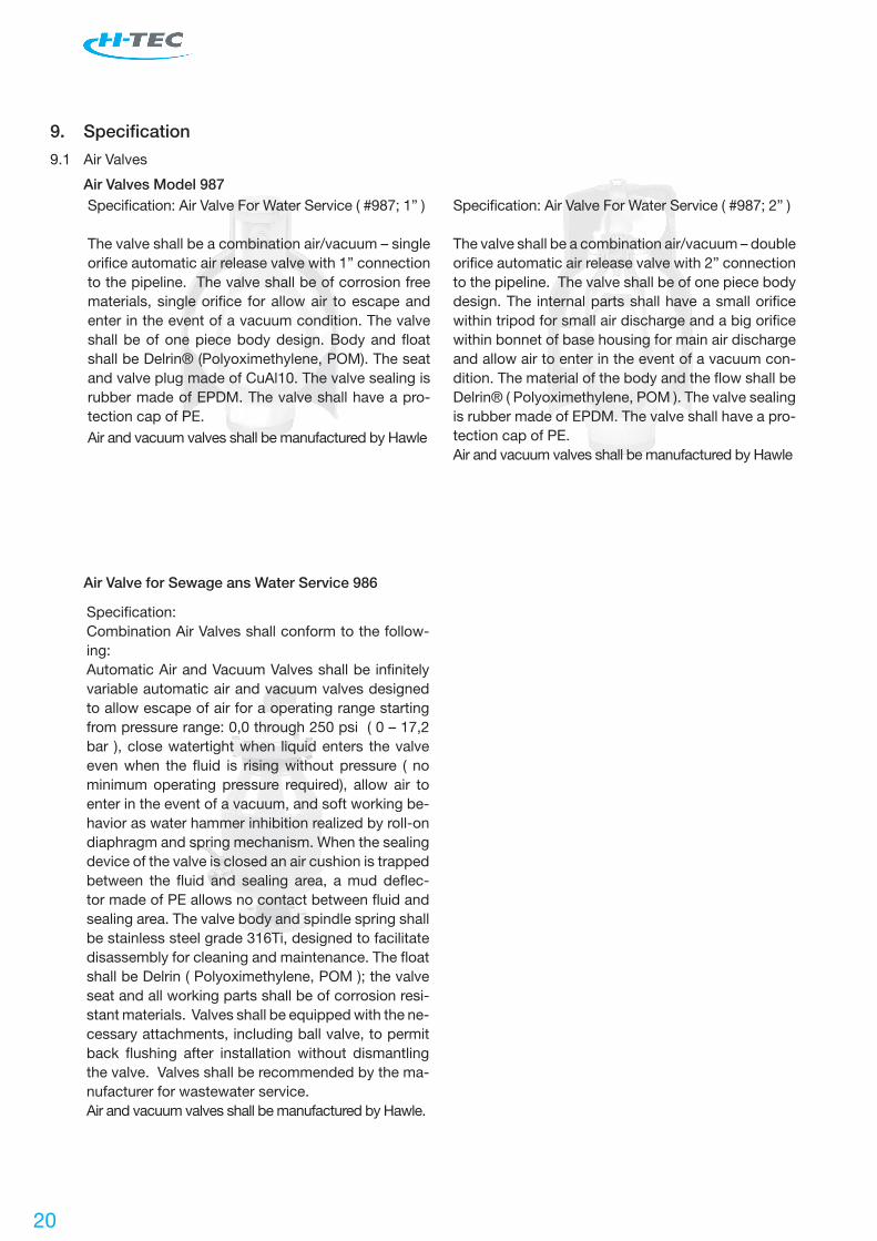
6.14 On waste water head pipes with automatic aeration
In some situations it is necessary to blow air into the pressure line via a compressor or pressure tank at regular intervals, in addition to “normal” pumping.
In these cases we recommend the use of an air release stop, which is mounted at delivery (also possible later when already installed) on the valve outlet elbow. During “normal” pumping the air release stop is out of action. If, however, very high air quantities are supplied to the pressure line via a compressor or pressure tank,then the air release stop responds mechanically and closes the valve. After scavenging (air), the valve goes back to its “normal” operating state.
For more detailed information please contact our applications engineering department.
6.15 On waste water vacuum pipes
In waste water vacuum pipes only air release valves may be used. To this end a nonreturn valve shall be in stalled at the valve outlet side.
Warning: This nonreturn valve will reduce air release capacity!
6.16 Insulation
Valves installed directly on the main line are not very susceptible to freezing, since the water in the valve is “heated” by the water flowing in the main line. However, in case that an offset installation is necessary, i.e. in case of installation beside the main line, there is the danger of freezing.
In this case both the supply line to the valve and the valve proper must be insulated. The valve in the Air Valve Set is protected from frost by inserting a disk cut to size and consisting of insulating material of approx. 2“ in thickness with a hole in the centre (see drawing) is inserted halfway up the stand pipe. This disk must not seal tightly to ensure that air release and intake are not inhibited (approx. 10 holes with a diameter of 0.4 inch). The Air Valve in the manhole is protected from frost by lining the manhole walls and the manhole cover with insu- lating material (see drawing b).
In case of waste water valves, too, insulation may be sensible. Though there is usually no danger of freezing, the depositing of grease at the wall of the Air Valve will be increased by temperature differences.

17
Drawing a Drawing b
Air Valves installed in the open, for example below bridges, must also be insulated to be frost-resistant. In this case, insulation may be effected, for example, by backfilling the surface box with polystyrene chips. To discharge splash water a drainage pipe leading from the Air Valve into the open must be installed.
insulation
ø approx. 10 mminsulation
7. Pressure testing
Prior to delivery H-TEC air valves are tested, including functional testing at max. operating pressure and body testing at 1,5 times the operating pressure.
Prior to pressure testing of pipelines with Air Valve Set and/or Air Valve Sets the shut-off device must be clo- sed, otherwise the pipeline may be vented during the pressure test, rendering the result of the pressure test useless.
AV: Close shut-off device upstream of the valve.
AVS 992: Take Air Valve out of the Air Valve Set – the integrated shut-off device of the set closes automatically.
AVS 985: Close shut-off device by means of half turn.

18
8. Functional testing and maintenance
b c
a
Open surface box
Loosen screw a
Take off hood
Loosen screw b
Take out spindle support c
Maintenance of Air Valve 2”: - Clean body and seats - Blow out valve bore by means of compressed air (see also sectional view item 3.1.1)
Maintenance of Air Valve 1”: - Screw out seat and blow through - Clean valve seal (see also sectional view item 3.1.1)
On start-up of the valve once again (perform above steps in reverse order) venting must be clearly audible (loud hiss) during screwing in of the spindle support. Otherwise the procedure has to be repeated.
Pull out valve by means
of operating tube
Simultaneously the foot
valve closes the system
at the bottom
0
30
1545
8.1 Reasons for maintenance
Almost all potable waters and waste waters carry along suspended particles and tend to sedimentation. In waste water there are also grease deposits and larger foreign bodies accumulating in the Air Valve. To avoid malfunctions caused by dirt Air Valves must be checked and maintained, if necessary, at regular intervals.
8.2 Maintenance intervals
H-TEC recommends regular checks of Air Valves for potable water are demanded at least every 12 months. The exact maintenance interval depends on the quality of the water. The first maintenance will be done after 3 to 6 months after start-up and serves as a first reference value for further testing intervals. In case of waste water the maintenance intervals must be adapted to the conditions of the pipeline. Usually, the first Air Valves of a series of several valves are contaminated most heavily. There are no generally applica- ble rules for maintenance intervals.
8.3 Important maintenance work
This information leaflet can show only the most important steps of maintenance. Please follow our maintenan- ce instructions and comply with the safety hints.
Prior to working at air valves the valve must be shut off via gate valve and unpressurized via an appropriate
valve. Air valves represent one of the few automatic connections between the pipeline system and the ambien-
ce. Therefore, they have to be checked at regular intervals. (see also [2]).
8.3.1 Maintenance of Air Valve Set Model 992

19
8.3.2 Maintenance of Air Valve Set Model 985
All maintenance and service work can be done from the road surface, thus avoiding the dangers involved with entering manholes. The Air Valve can be flushed without being dismantled via the two flushing ports (5a / 5b). To this end hoses must be connected to the two flushing ports (5a / 5b) in such a way that the inside pressure is released safely after opening the ball valves (4 / 6). Flushing is performed by passing water from 5a to 5b, possibly adding some clea- ning agent.
4. Put the valve (7) onto the bayonet coupling from abo- ve and lock it clockwise. Put the 3/2-way ball valve (6) back in place and tighten the screwed unions manually until the connections are tight. Put on the operating tube (3). Close the ball valve of the lower flushing orifice (4). Slowly open the shut-off valve (12) below the air valve (counterclockwise). After opening offset the operating tube again by 180° (safety func- tion against automatic unlocking of the Air Valve). Visual inspection of all connections and flushing ori- fices.
If there are any foreign bodies in the valve that cannot be flushed out via the bottom flushing orifice, the valve should be dismantled, opened, and the foreign body be removed. To this end proceed as follows:
1. Take off the cover (1) from the chamber cylinder (2). Close the shut-off valve by means of the offset opera- ting tube (3) by a half turn (clockwise). – The operating tube must be offset by 180° before!
Warning: Even after closing the shut-off valve the air valve is pressurized, therefore open the ball val- ve (4) on the lateral flushing pipe carefully and only after mounting a hose at the flushing port provided for this purpose (5b). Discharge any emerging waste wa- ter safely. Dismantle the 3/2-way ball valve (6). To this end loosen the screwed union.
2. Pull the operating tube (3) upward and out of the air valve set. Turn the valve (7) counterclockwise until the bayonet coupling (8) is loosened. Pull the valve up- ward and out of the chamber cylinder (2) at the two eye bolts (9) by means of a suitable lifting tool. Any residual water is discharged via the drainage device. If this is not desired, install an end fitting (13) and pump out the “chamber”.
3. Open the body screws (10). Clean the valve inside (use a cleaning solution, if required, in case of persi- stent dirt, let the agent work itself in for a while, befo- re cleaning by means of a brush). Screw the valve bonnet (11) back on again, making sure that the toro- idal sealing ring is fitting properly. Prior to installation of the Air Valve clean all sealing surfaces.
13
8
12
9
2
3
5b
6
1
11
10
4
5a
7
20
9. Specification
9.1 Air Valves
Air Valves Model 987Specification: Air Valve For Water Service ( #987; 1” )
The valve shall be a combination air/vacuum – single orifice automatic air release valve with 1” connection to the pipeline. The valve shall be of corrosion free materials, single orifice for allow air to escape and enter in the event of a vacuum condition. The valve shall be of one piece body design. Body and float shall be Delrin® (Polyoximethylene, POM). The seat and valve plug made of CuAl10. The valve sealing is rubber made of EPDM. The valve shall have a pro-tection cap of PE.Air and vacuum valves shall be manufactured by Hawle
Specification: Air Valve For Water Service ( #987; 2” )
The valve shall be a combination air/vacuum – double orifice automatic air release valve with 2” connection to the pipeline. The valve shall be of one piece body design. The internal parts shall have a small orifice within tripod for small air discharge and a big orifice within bonnet of base housing for main air discharge and allow air to enter in the event of a vacuum con-dition. The material of the body and the flow shall be Delrin® ( Polyoximethylene, POM ). The valve sealing is rubber made of EPDM. The valve shall have a pro-tection cap of PE.Air and vacuum valves shall be manufactured by Hawle
Air Valve for Sewage ans Water Service 986
Specification: Combination Air Valves shall conform to the follow-ing:Automatic Air and Vacuum Valves shall be infinitely variable automatic air and vacuum valves designed to allow escape of air for a operating range starting from pressure range: 0,0 through 250 psi ( 0 – 17,2 bar ), close watertight when liquid enters the valve even when the fluid is rising without pressure ( no minimum operating pressure required), allow air to enter in the event of a vacuum, and soft working be-havior as water hammer inhibition realized by roll-on diaphragm and spring mechanism. When the sealing device of the valve is closed an air cushion is trapped between the fluid and sealing area, a mud deflec-tor made of PE allows no contact between fluid and sealing area. The valve body and spindle spring shall be stainless steel grade 316Ti, designed to facilitate disassembly for cleaning and maintenance. The float shall be Delrin ( Polyoximethylene, POM ); the valve seat and all working parts shall be of corrosion resi-stant materials. Valves shall be equipped with the ne-cessary attachments, including ball valve, to permit back flushing after installation without dismantling the valve. Valves shall be recommended by the ma-nufacturer for wastewater service.Air and vacuum valves shall be manufactured by Hawle.

21
Automatic air valve with standpipe of stainless steel (replacing a shaft), BAIO® spigot end or flanged con-nection drilled, of Ductile Iron (GJS-400), high-quality corrosion protection by fluidized bed epoxy powder coating inside and outside. The valve shall be a com-bination air/vacuum – double orifice automatic air release valve. The valve shall be of one piece body design. The internal parts shall have a small orifice within tripod for small air discharge and a big orifice within bonnet of base housing for main air discharge and allow air to enter in the event of a vacuum con-dition. The material of the body and the flow shall be Delrin® ( Polyoximethylene, POM ). The valve sealing is rubber made of EPDM. Standpipe of stainless steel suitable for above ground and underground installati-on, standpipe with drain-off fitting. Air and vacuum valves shall be manufactured by Hawle.
9.2 Air Valve sets
Automatic Air Valve Set ( #992 ) Valve with Shaft for
Underground Installation
Automatic Air and Vacuum Valves shall be infinitely variable automatic air and vacuum valves designed to allow escape of air for a operating range starting from pressure range: 0,0 through 250 psi ( 0 – 17,2 bar ), close watertight when liquid enters the valve even when the fluid is rising without pressure ( no minimum operating pressure required), allow air to enter in the event of a vacuum, and soft working behaviour as water hammer inhibition realized by roll-on diaphragm and spring mechanism. When the sealing device of the valve is closed an air cushion is trapped between the fluid and sealing area, a mud deflector made of PE allows no contact between fluid and sealing area. The valve body and spindle spring shall be stainless steel grade 316Ti, designed to fa-cilitate disassembly for cleaning and maintenance. The float shall be Delrin ( Polyoximethylene, POM ); the valve seat and all working parts shall be of cor-rosion resistant materials. Valves shall be equipped with the necessary attachments, including ball valve, to permit back flushing after installation without dis-mantling the valve. Valves shall be recommended by the manufacturer for wastewater service. The air valve set is provided with a PE shaft repla-cing a manhole, a shut-off device with a steel plate of hard-rolled stainless steel and straight-through bore when open, two maintenance outlets with hose connection and ball valve, lateral outlet for waste air with PE elbow as swivelling device equipped with additional protection grid, drain-off fitting at the shaft bottom. After closing the shut-off device by integra-ted operating tool and removal of the upper ball valve the air valve can be taken out of the shaft for main-tenance purposes. Valves shall be recommended by the manufacturer for wastewater service.Air and vacuum valves shall be manufactured by Hawle
Air Valve Set for Operating Range 0 – 250 psi /
0 – 17,2 bar ( #985 )

22 23
Component 80 Material
1 Spigot end 80 GGG 40, fluidized bed epoxy powder coated
2 Shut-off facility GGG 40, fluidized bed epoxy powder coated
3 Air Valve steel, St. 37 – fluidized bed epoxy powder coated
4 Chamber cylinder PE
5 Cover PE
6 Three-way ball valve PVC
7 Hose coupling PA 6 GF 25
8 Ball valve stainless steel
9 Operating rod square steel St. 37 – fluidized bed epoxy powder coated
10 Bottom plate sheet steel St. 37 – fluidized bed epoxy powder coated
11 Drain-off fitting GGG 40, fluidized bed epoxy powder coated
Accessories
12 End fitting (please observe surcharge!) POM
13 Manhole cover GGG 40, bituminized
Manhole ring GG 24, bituminized
Drawing representing Air Valve Set with BAIO® spigot end 3“
Air Valve Set Model 985 with spigot endAir Valve Set Model 985 with flange Air Valve Set Model 985 with PE tailMedium: raw and potable water, domestic and industrial waste waterOperating range: 0 – 16 bar

Automatic Air Valve Set Model 992 with spigot endAutomatic Air Valve Set Model 992 with flange Automatic Air Valve Set Model 992 with PE tailMedium: potable waterOperating pressure: 14.5 - 250 PSI (0,1 – 6 bar) and 1.5 - 87 PSI (0,1 - 6 bar)
Component Material
1.1 Inlet flange GGG 40
1.2.1 Fitting GGG 40
1.2.2 O-ring NBR
1.2.3 Grip ring POM
1.3 O-ring NBR
1.4 Sealing flange Rg 7
1.5 Foot valve POM
1.6 Spring case MS 58
1.7 Pressure spring stainless steel
1.8 Hexagon screw M 10 x 35 DIN 933 stainless steel
2.1 Bonnet POM
2.2 O-ring NBR
2.3 Seat CuZn35Pb3As / EPDM
2.3.1 Hexagon screw stainless steel
2.4 Locking plate stainless steel
2.5 Locknut MS 58
2.6.1 Bottom part of body POM
2.6.2 Air valve support POM
2.7.1 Float bottom part POM
2.7.2 Ballast EPDM
2.7.3 Float top part POM / EPDM
2.7.4 Sealing screw stainless steel
2.7.5 Fan type lock washer stainless steel
2.8.1 Sealing cover POM
2.8.2 Seat for sealing cover EPDM
2.8.3 O-ring NBR
2.9 O-ring NBR
2.10 Hexagon nut stainless steel
2.11 Washer stainless steel
2.12 Hexagon socket bolt stainless steel
2.13 O-ring NBR
2.14 Insect protective grid stainless steel
3 Operating tube stainless steel
4 Centring cap GGG 400
4.1 Hexagon screw M 8 x 10 DIN 931 stainless steel
5 Stand pipe stainless steel
6 Lock ring GGG 40
7 Hexagon bolt M 16 x 50 DIN 931 stainless steel
8 Hexagon nut M 16 DIN 934 stainless steel
9 Washer stainless steel
10 Sealing EPDM
11 Cover EPDM
12 Spindle support GGG 40
13 Operating screw Ms 58
14 Hood PE
15 Hexagon screw M 8 x 60 DIN 931 stainless steel
16 Washer stainless steel
17 Drain pipe PE
The following abbreviations are used:
AV = air valve
AVS = air valve set
ARV = air release valve
17

Edition September 2009- Subject to change
1700 Enterprise Way, Suite 116 – Marietta, GA 30067 – Phone +1 770-818-0670 – Fax: +1 770-818-0671