Embed Size (px)
Citation preview
-
Model AD-29A Automatic Air Spray Gun and Can Marking System
Part 107 979A
NORDSON CORPORATION. AMHERST, OHIO. USA
21’-454d TECHNICAL PUBLICATION Nordson Corporation l Finishing Equipment Division
ISSUED 4/85
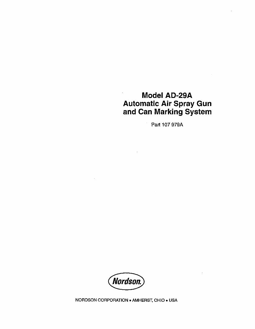
CONTENTS
SUPERSEDES
Description ........................... 21-15-l.
Specifications .......................... -2
Theory of Operation ...................... -4
Installation ............. ; ............. -5
Operation ........................... -7
Maintenance .......................... -8
Troubleshooting ......................... -9
Disassembly ........................... -10
Exploded View .......................... -12
AD-29A Gun Parts List ..................... 713
System Parts List ........................ -15
-.
-
LITHO U S A.
0 NO&on Nordson corporation TECHNICAL PUBLICATION 21-15-l Finishing Equipment Division, Amherst, Ohio 44001
SUPERSEDES ISSUED 4185
NORDSON
CAN MARKING SYSTEM
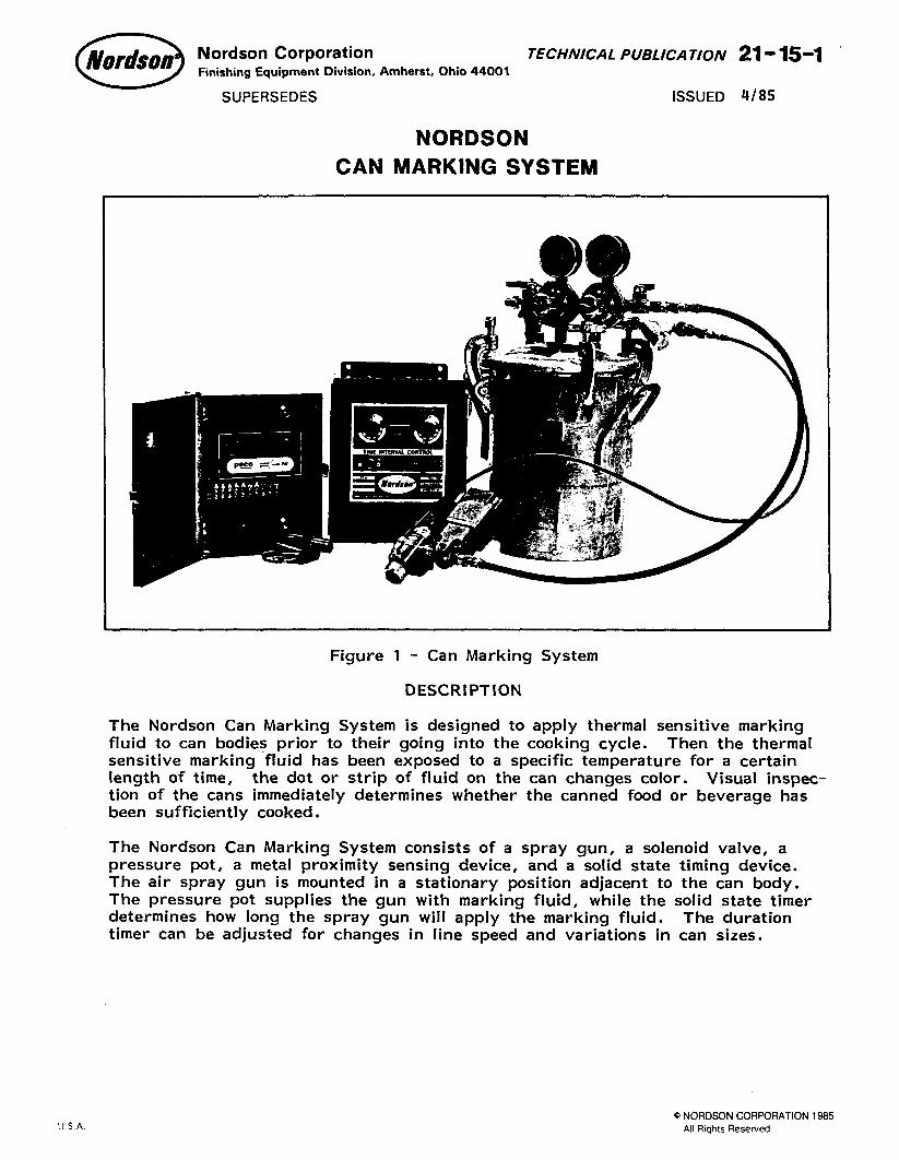
Figure 1 - Can Marking System
DESCRIPTION
The Nordson Can Marking System is designed to apply thermal sensitive marking
fluid to can bodies prior to their going into the cooking cycle. Then the thermal sensitive marking fluid has been exposed to a specific temperature for a certain length of time, the dot or strip of fluid on the can changes color. Visual inspec- tion of the cans immediately determines whether the canned food or beverage has been sufficiently cooked.
The Nordson Can Marking System consists of a spray gun, a solenoid valve, a pressure pot, a metal proximity sensing device, and a solid state timing device. The air spray gun is mounted in a stationary position adjacent to the can body.
The pressure pot supplies the gun with marking fluid, while the solid state timer determines how long the spray gun will apply the marking fluid. The duration timer can be adjusted for changes in line speed and variations in can sizes.
lITHO USA. Q NORDSON CORPORATION 1985
All Rights Reserved
21-15-2 TECHNICAL PUBLICATION Nordson Corporation l Finishing Equipment Division
ISSUED 4185 SUPERSEDES
SPECIFICATIONS
U.S.A. METRIC
Operating Temperature Ambient
Operating Air Pressure 2
- Pot 10-40 PSIG .7-2.8 kg/cm
Operating Air Pressure - Gun 45-70 PSIG 3.2-4.9 kg/cm 2
Air Consumption - Gun Depends on appli- cation 2 SCFM maximum
.944 Iiters/sec.
Electrical Requirements - Controls 115 VAC, SO/SO Hz., 50 watts
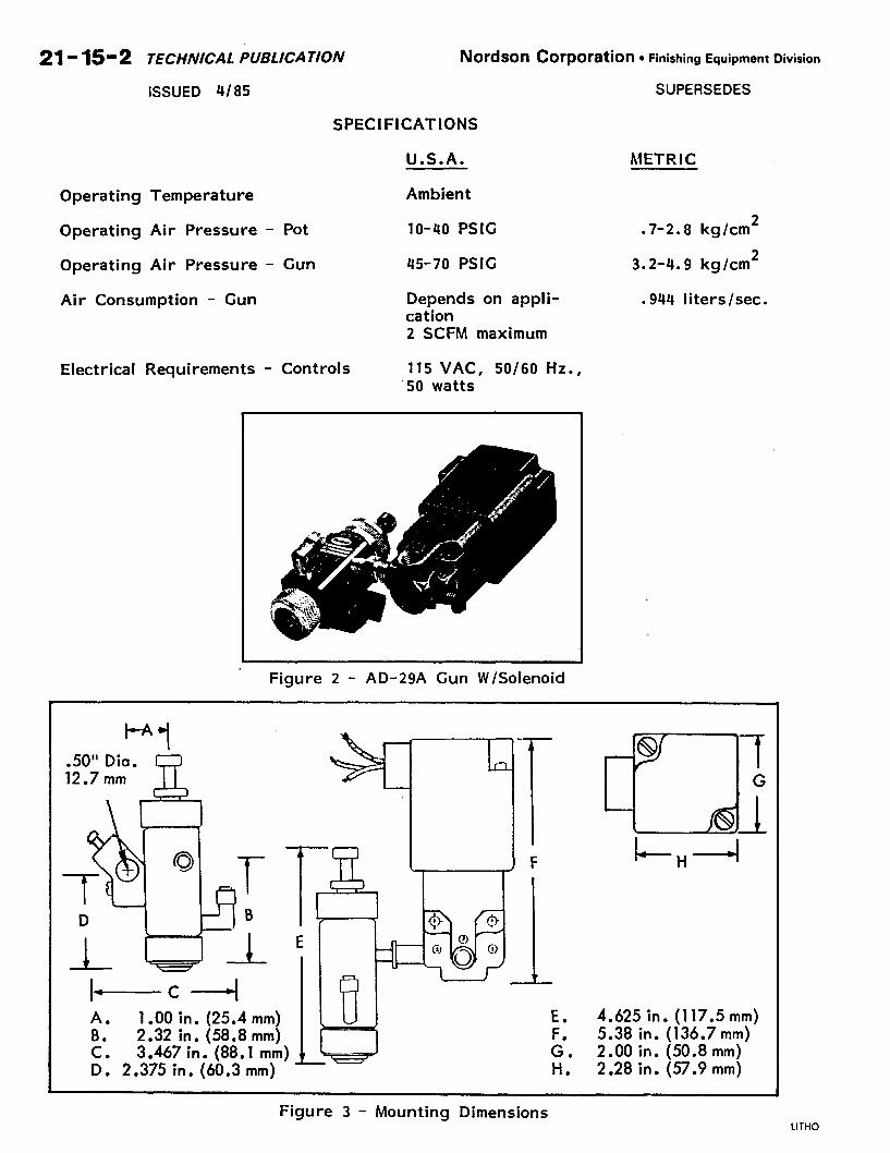
Figure 2 - AD-29A Gun W/Solenoid
I- c4 A. 1 .OO in. (25.4 mm) U E. B. 2.32 in. (58.8 mm)
LW
F. c. 3.467 in. (88.1 mm) G. D. 2.375 in. (60.3 mm) Ii.
4.625 in. (117.5 mm) 5.38 in. (136.7mm) 2.00 in. (50.8 mm) 2.28 in. (57.9 mm)
-
Figure 3 - Mounting Dimensions LITHO U.S.A.
0 NO&on Nordson corporation TECHNICAL PUBLICATION 21- 15-3 Finishing Equipment Division, Amherst, Ohio 44001
SUPERSEDES ISSUED 4/85
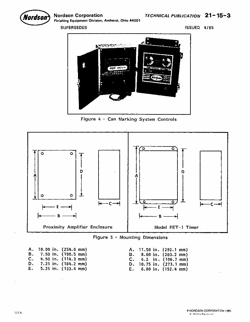
Figure 4 - Can Marking System Controls
b-c-4
Proximity Amplifier Enclosure
r D
I - +--+I
Model FET-1 Timer
Figure 5 - Mounting Dimensions
A. 10.00 in. (254.0 mm) A. 11.50 in. (292.1 mm) B. 7.50 in. (190.5 mm) B. 8.00 in. (203.2 mm) c. 4.50 in. (114.3 mm) c. 4.2 in. (106.7 mm) D. 7.25 in. (184.2 mm) D. 10.75 in. (273.1 mm) E. 5.25 in. (133.4 mm) E. 6.00 in. (152.4 mm)
:ITHO U S A. Q NORDSON CORPORATlON 1985
All R,-htc F)ecor~md
21- 15-4 TECHNICAL PUBLICATION Nordson COtpOratiOn l Finishing Equipment Division
ISSUED 4185 SUPERSEDES
Proximity AD-29A
Dua I Regulators
Main Air SUPP’Y
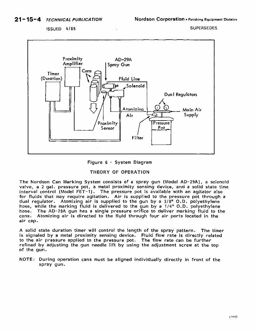
Figure 6 - System Diagram
THEORY OF OPERATION
The Nordson Can Marking System consists of a spray gun (Model AD-29A), a solenoid valve, a 2 gal. pressure pot, a metal proximity sensing device, and a solid state time interval control (Model FET-1). The pressure pot is available with an agitator also
for fluids that may require agitation. Air is supplied to the pressure pot through a dual regulator. Atomizing air is supplied to the gun by a 3/8” O.D. polyethylene hose, while the marking fluid is delivered to the gun by a l/4” 0. D. polyethylene hose. The AD-29A gun has a single pressure orifice to deliver marking fluid to the cans. Atomizing air is directed to the fluid through four air ports located in the air cap.
A solid state duration timer will control the length of the spray pattern. The timer is signaled by a metal proximity sensing device. Fluid flow rate is directly related to the air pressure applied to the pressure pot. The flow rate can be further refined by adjusting the gun needle lift by using the adjustment screw at the top of the gun.
NOTE: During operation cans must be aligned individually directly in front of the spray gun.
LITHO U.S A.
Nordson Corporation TECHNICAL PUBLICATION 21- Is-5 . Finishing Equipment Division, Amherst, Ohio 44001
SUPERSEDES ISSUED 4/85
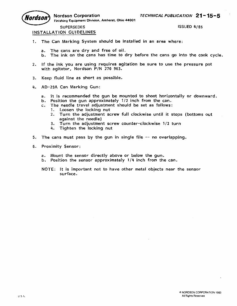
INSTALLATION GUIDELINES
1. The Can Marking System should be installed in an area where:
a. The cans are dry and free of oil. b. The ink on the cans has time to dry before the cans go into the cook cycle.
2. If the ink you are using requires agitation be sure to use the pressure pot with agitator, Nordson P/N 270 963.
3. Keep fluid line as short as possible.
4. AD-29A Can Marking Gun:
a. It is recommended the gun be mounted to shoot horizontally or downward.
b. Position the gun approximately l/2 inch from the can. c. The needle travel adjustment should be set as follows:
1. Loosen the locking nut 2. Turn the adjustment screw full clockwise until it stops (bottoms out
against the needle) 3. Turn the adjustment screw counter-clockwise l/2 turn 4. Tighten the locking nut
5. The cans must pass by the gun in single file -- no overlapping.
6. Proximity Sensor:
a. Mount the sensor directly above or below the gun. b. Position the sensor approximately l/4 inch from the can.
NOTE: It is important not to have other metal objects near the sensor surface.
L”i’:J IJ S A.
.
Q NORDSON CORPORATION 1985 All Rights Reserved
21-15-6 TECHNICAL PUBLICATION Nordson COrpOratbn l Finishing Equipment Division
ISSUED 4/85 SUPERSEDES INSTALLATION
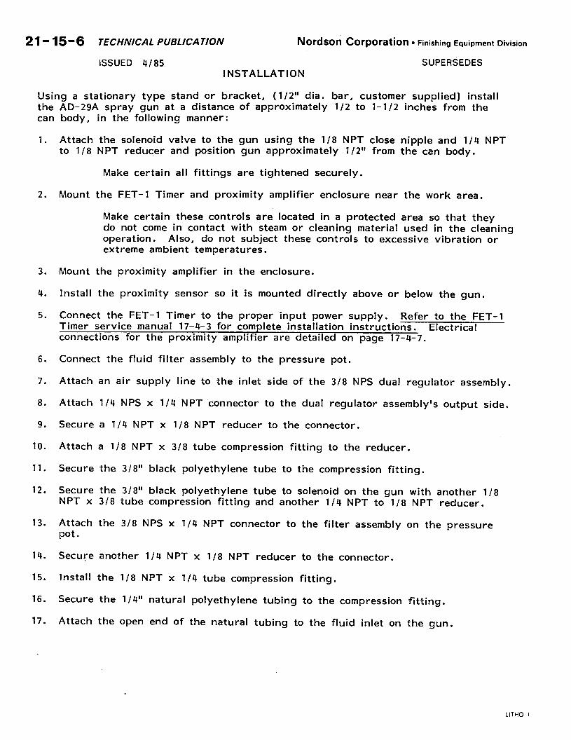
Using a stationary type stand or bracket, (l/2” dia. bar, customer supplied) install
the AD-29A spray gun at a distance of approximately l/2 to l-1/2 inches from the can body, in the following manner:
1. Attach the solenoid valve to the gun using the l/8 NPT close nipple and l/4 NPT to l/8 NPT reducer and position gun approximately l/2” from the can body.
Make certain all fittings are tightened securely.
2. Mount the FET-1 Timer and proximity amplifier enclosure near the work area.
Make certain these controls are located in a protected area so that they do not come in contact with steam or cleaning material used in the cleaning operation. Also, do not subject these controls to excessive vibration or extreme ambient temperatures.
3. Mount the proximity amplifier in the enclosure.
4. Install the proximity sensor so it is mounted directly above or below the gun.
5. Connect the FET-1 Timer to the proper input power supply. Refer to the FET-1 Timer service manual 17-4-3 for complete installation instructions. Electrical connections for the proximity amplifier are detailed on page 17-4-7.
6. Connect the fluid filter assembly to the pressure pot. -_
7. Attach an air supply line to the inlet side of the 3/8 NPS dual regulator assembly.
8. Attach l/4 NPS x l/4 NPT connector to the dual regulator assembly’s output side.
9. Secure a l/4 NPT x l/8 NPT reducer to the connector.
10. Attach a l/8 NPT x 3/8 tube compression fitting to the reducer.
11. Secure the 3/8” black polyethylene tube to the compression fitting.
12. Secure the 3/8” black polyethylene tube to solenoid on the gun with another l/8 NPT x 3/8 tube compression fitting and another l/4 NPT to l/8 NPT reducer.
13. Attach the 3/8 NPS x l/4 NPT connector to the filter assembly on the pressure pot.
14. Secure another l/4 NPT x l/8 NPT reducer to the connector.
15. Install the 118 NPT x l/4 tube compression fitting.
16. Secure the l/S” natural polyethylene tubing to the compression fitting.
17. Attach the open end of the natural tubing to the fluid inlet on the gun.
LITHO U.S.A.
Nordson Corporation TECHNICAL PUBLICATION 21- 15-7 Finishing Equipment Division, Amherst, Ohio 44001
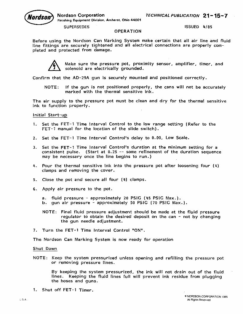
SUPERSEDES ISSUED 4/85 OPERATION
Before using the Nordson Can Marking System make certain that all air line and fluid line fittings are securely tightened and all electrical connections are properly com-
pleted and protected from damage.
A 5 Make sure the pressure pot, proximity sensor, amplifier, timer, and solenoid are electrically grounded.
Confirm that the AD-29A gun is securely mounted and positioned correctly.
NOTE: If the gun is not positioned properly, the cans will not be accurately marked with the thermal sensitive ink.
The air supply to the pressure pot must be clean and dry for the thermal sensitive ink to function properly.
Initial Start-up
1. Set the FET-1 Time Interval Control to the low range setting (Refer to the FET-1 manual for the location of the slide switch).
2. Set the FET-1 Time Interval Control’s delay to 0.00, Low Scale.
3. Set the FET-1 Time Interval Control’s duration at the minimum setting for a consistent pulse. (Start at 0.25 -- some refinement of the duration sequence
may be necessary once the line begins to run.)
4. Pour the thermal sensitive ink into the pressure pot after loosening four (4) clamps and removing the cover.
5. Close the pot and secure all four (4) clamps.
6. Apply air pressure to the pot.
a. fluid pressure - approximately 20 PSIC (45 PSIG Max.). b. gun air pressure - approximately 50 PSIC (70 PSIG Max.).
NOTE: Final fluid pressure adjustment should be made at the fluid pressure regulator to obtain the desired deposit on the can - not by changing the gun needle adjustment.
7. Turn the FET-1 Time Interval Control llON’l.
The Nordson Can Marking System is now ready for operation
Shut Down
NOTE: Keep the system pressurized unless opening and refilling the pressure pot or removing pressure lines.
By keeping the system pressurized, the ink will not drain out of the fluid lines. Keeping the fluid lines full will prevent ink residue from plugging the hoses and guns.
1. Shut off FET-1 Timer.
Q, NORDSON CORPORATION 1985 All Rights Reserved
21-15-8 TECHNICAL PUBLICATION
ISSUED 4/85
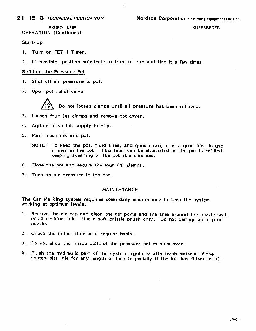
OPERATION (Continued)
Nordson COrpO!‘atiOn l Finishing Equipment Division
SUPERSEDES
Start-Up
1. Turn on FET-1 Timer.
2. If possible, position substrate in front of gun and fire it a few times.
Refillina the Pressure Pot
1. Shut off air pressure to pot.
2. Open pot relief valve.
A T 0 es Do not loosen clamps until all pressure has been relieved.
3. Loosen four (4) clamps and remove pot cover.
4. Agitate fresh ink supply briefly.
5. Pour fresh ink into pot.
NOTE: To keep the pot, fluid lines, and guns clean, it is a good idea to use a liner in the pot. This liner can be alternated as the pot is refilled keeping skimming of the pot at a minimum.
6. Close the pot and secure the four (4) clamps.
7. Turn on air pressure to the pot.
MAINTENANCE
The Can Marking system requires some daily maintenance to keep the system working at optimum levels.
1. Remove the air cap and clean the air ports and the area around the nozzle seat of all residual ink. nozzle.
Use a soft bristle brush only. Do not damage air cap or
2. Check the inline filter on a regular basis.
3. Do not allow the inside walls of the pressure pot to skim over.
4. Flush the hydraulic part of the system regularly with fresh material if the system sits idle for any length of time (especially if the ink has fillers in it).
LITHO U.S A.
Nordson Corporation TECHNICAL PUBLICATION 21-15-g Finishing Equipment Division, Amherst, Ohio 44001
SUPERSEDES ISSUED 4/85
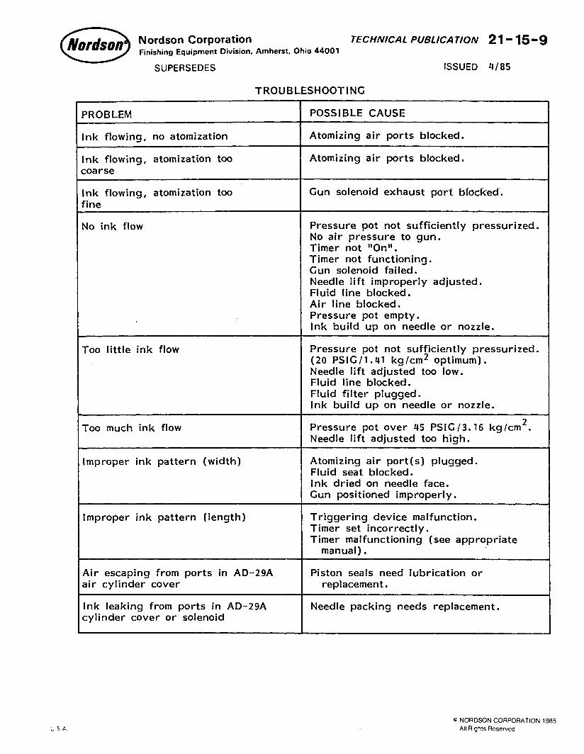
TROUBLESHOOTING
PROBLEM POSSIBLE CAUSE
Ink flowing, no atomization Atomizing air ports blocked.
Ink flowing, atomization too Atomizing air ports blocked.
soarse
Ink flowing, atomization too Gun solenoid exhaust port blocked.
fine
No ink flow Pressure pot not sufficiently pressurized. No air pressure to gun. Timer not ‘IOn? Timer not functioning. Gun solenoid failed. Needle lift improperly adjusted. Fluid line blocked. Air line blocked. Pressure pot empty. Ink build up on needle or nozzle.
Too little ink flow Pressure pot not sufficiently pressurized. (20 PSIG / 1.41 kg /cm2 optimum). Needle lift adjusted too low. Fluid line blocked. Fluid filter plugged. Ink build up on needle or nozzle.
Too much ink flow Pressure pot over 45 PSIW3.16 kg/cm2. Needle lift adjusted too high.
Improper ink pattern (width) Atomizing air port(s) plugged. Fluid seat blocked. Ink dried on needle face. Gun positioned improperly.
Improper ink pattern (length) Triggering device malfunction. Timer set incorrectly. Timer malfunctioning (see appropriate
manual).
Air escaping from ports in AD-29A air cylinder cover
Ink leaking from ports in AD-29A cylinder cover or solenoid
Piston seals need lubrication or replacement.
Needle packing needs replacement.
-
@ NORDSON CORPORATION 1985 All Rights Reserved
21- 159 10 TECHNICAL PUBLICATION Nordson COrpOratiOn l Finishing Equipment Division
ISSUED Q/85 SUPERSEDES
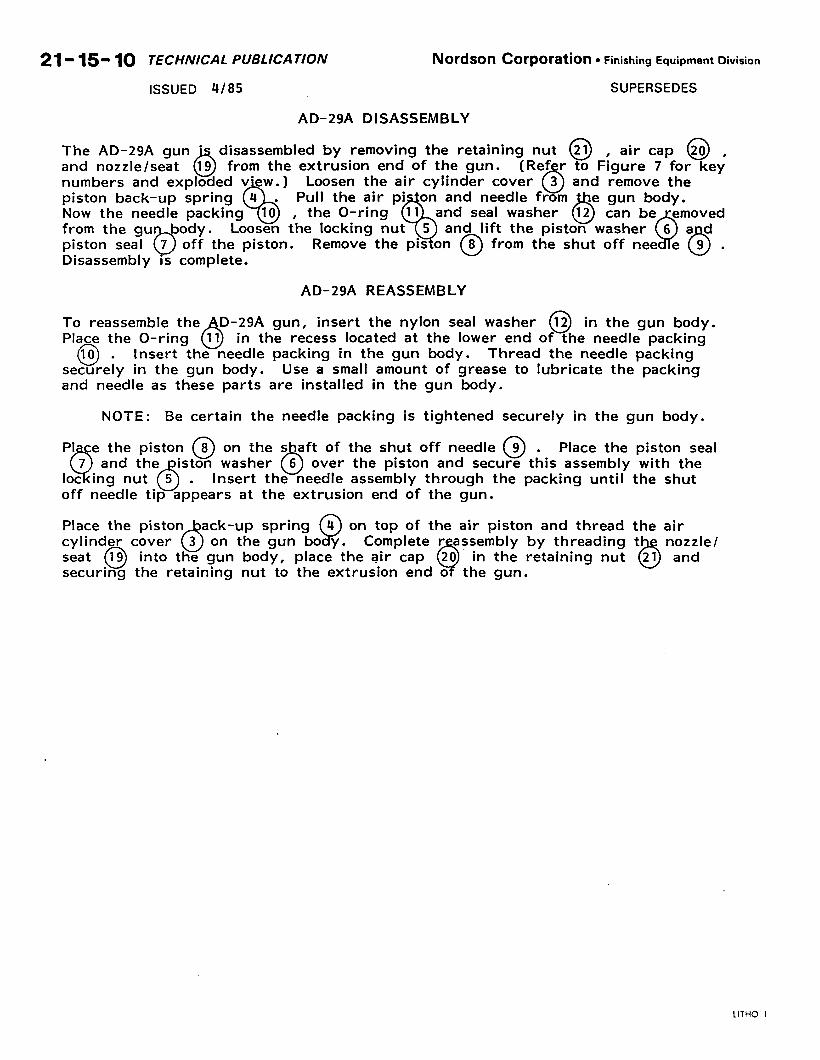
-- AD-29A DISASSEMBLY
The AD-29A gun ’ disassembled by removing
and nozzle/seat from the extrusion end of the gun.
numbers and Loosen the air cylinder
AD-29A REASSEMBLY
To reassemble the D-29A gun, insert the nylon seal washer 12 in the gun body. Place the O-ring
0 0
Q 11 in the recess located at the lower end of the needle packing
10 . Insert the needle packing in the gun body. Thread the needle packing
securely in the gun body. Use a small amount of grease to lubricate the packing and needle as these parts are installed in the gun body.
NOTE: Be certain the needle packing is tightened securely in the gun body.
the shaft of the shut off needle @ .
0 Place the piston seal
6 over the piston and secure this assembly with the Insert the needle assembly through the packing until the shut
at the extrusion end of the gun.
Place the piston ack-up cylinder cover
0 6
on top of the air piston and thread the air 3 on the gun Complete r assembly by threading
seat 19 into the gun body, place the air cap 20 in the retaining nut 6 securing the retaining nut to the extrusion end o the gun.
-.
-
LITHO U.S.A.
Nordson Corporation TECHNICAL PUBLICATION 21115- 11 Finishing Equipment Division, Amherst, Ohio 44001
SUPERSEDES ISSUED f+/85
RESERVED FOR FUTURE USE
-
@ NORDSON CORPORATION 1985
All Rtghts Reserved
2.1,15- 12 TECHNICAL PUBLICATION Nordson Corporation l Finishing Equipment Division
ISSUED f+/85 SUPERSEDES
21
14
-
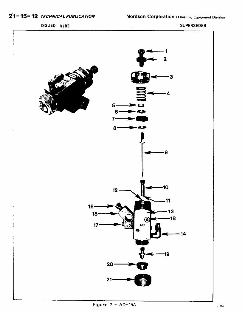
Figure 7 - AD-29A LITHO U.S A.
--
a NO&On Nordson Corporation TECHNICAL PUBLICATION 219 159 13 Finishing Equipment Division, Amherst, Ohio 44001
SUPERSEDES
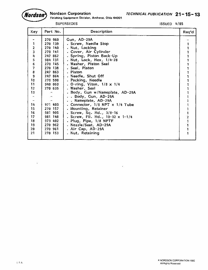
Key Part No. Description
270 960 Gun, AD-29A
1 270 139 . Screw, Needle Stop 2 270 140 . Nut, Locking 3 270 141 . Cover, Air Cylinder 4 247 862 . Spring, Piston Back-Up 5 984 131 . Nut, Lock, Hex, l/4-28 6 270 145 . Washer, Piston Seal 7 270 138 . Seal, Piston 8 247 863 Piston 9 247 864 : Needle, Shut Off
10 270 598 . Packing, Needle 11 940 060 . O-ring, Viton, l/8 x l/4 12 270 635 . Washer, Seal 13 . Body, Gun w/Nameplate, AD-29A
. . Body, Gun, AD-29A Nameplate, AD-29A
14 971 403 1 Connector, l/8 NPT x l/4 Tube 15 270 157 . Mounting, Retainer 16 981 905 . Screw, Sq. Hd., 3/8-16 17 981 148 . Screw, Fil. Hd., lo-32 x l-1/4 18 973 402 Plug, Pipe, l/8 NPTF 19 270 962 : Nozzle/Seat, AD-29A 20 270 961 . Air Cap, AD-29A 21 270 153 . Nut, Retaining
ISSUED W85
Req’d
1 1 1 1 1 1 1 1 1 1 1 1 1 1 1 1 1 1 2 1 1 1 1
-
@ NORDSON CORPORATION 1985 All Rights Reserved
21- 15- 14 TECHNICAL PUBLICATION Nordson COrpOratiOtl l Finishing Equipment Division
ISSUED Q/85 SUPERSEDES
‘5
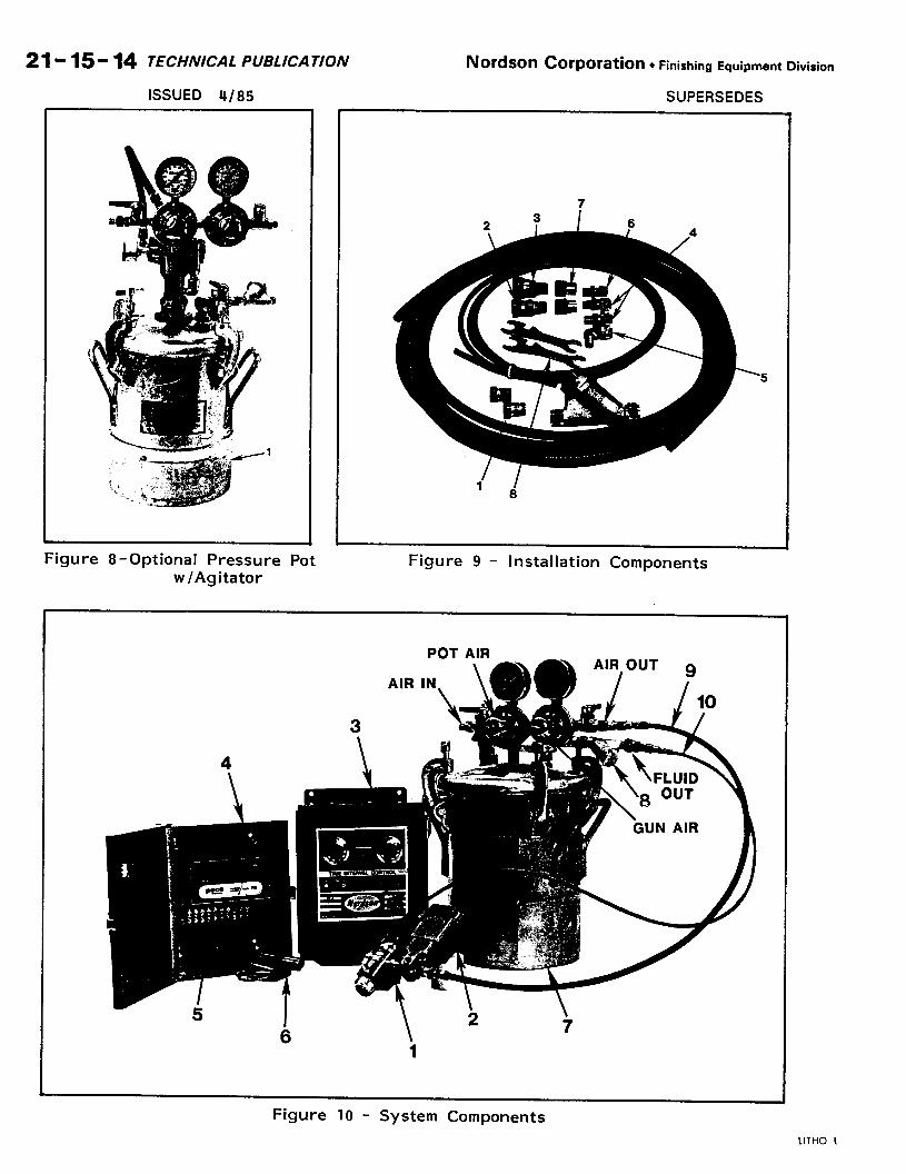
Figure 8-Optional Pressure Pot Figure 9 - Installation Components w/Agitator
POT AIR
-
Figure 10 - System Components
LITHO U.S.A.
.--
0 NO&On Nordson Corporation TECHNICAL PUBLlCATlON 2 I- 15 - 15 Finishing Equipment Division, Amherst, Ohio 44001
SUPERSEDES ISSUED 4/85
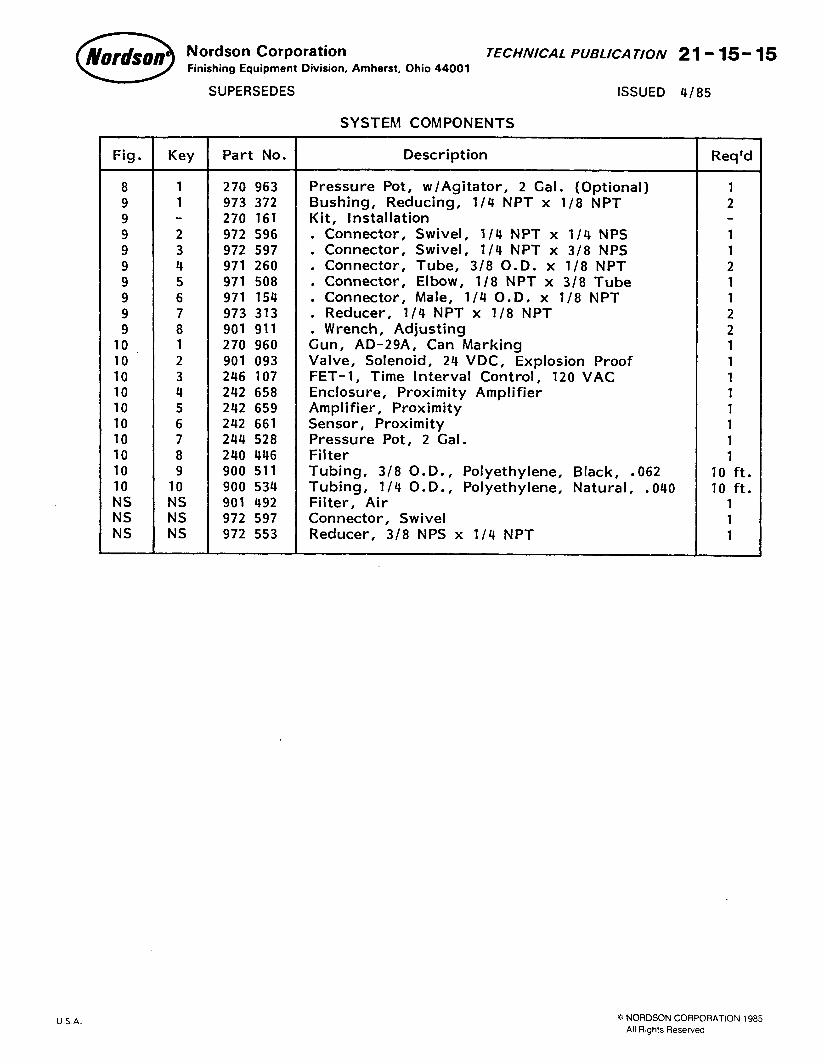
SYSTEM COMPONENTS
Fig. Key Part No. Description Req’d
8 1 270 963 Pressure Pot, w/Agitator, 2 Gal. (Optional) 1 9 1 973 372 Bushing, Reducing, l/4 NPT x l/8 NPT 2 9 - 270 161 Kit, Installation
9 2 972 596 . Connector, Swivel, l/4 NPT x l/4 NPS 1
9 3 972 597 Connector, Swivel, l/4 NPT x 318 NPS 1
9 4 971 260 : Connector, Tube, 3/8 O.D. x l/8 NPT 2 9 5 971 508 . Connector, El bow, 118 NPT x 318 Tube 1
9 6 971 154 . Connector, Male, 114 O.D. x l/8 NPT 1
9 7 973 313 . Reducer, l/4 NPT x l/8 NPT 2 9 8 901 911 Wrench, Adjusting 2
10. 1 270 960 Gun, AD-29A, Can Marking 1
10 2 901 093 Valve, Solenoid, 24 VDC, Explosion Proof 1 10 3 246 107 FET-1, Time Interval Control, 120 VAC 1 10 4 242 658 Enclosure, Proximity Amplifier 1 10 5 242 659 Amplifier, Proximity 1 10 6 242 661 Sensor, Proximity 1 10 7 244 528 Pressure Pot, 2 Gal. 1 10 8 240 446 Filter 1 10 9 900 511 Tubing, 3/8 O.D., Polyethylene, Black, .062 10 ft. 10 10 900 534 Tubing, l/4 O.D., Polyethylene, Natural, .040 10 ft. NS NS 901 492 Filter, Air 1 NS NS 972 597 Connector, Swivel 1 NS NS 972 553 Reducer, 3/8 NPS x l/4 NPT 1
.-
LITHO U S A. @ NORDSON CORPORATION 1985
All Rights Reserved