Embed Size (px)
Citation preview

Automated Valves:Optimization of ProcessControl and Profits
Günter Öxler

2
Table of Contents
Introduction . . . . . . . . . . . . . . . . . . . . . . . . . . . . . . . . . . . . . . . . . . . . . . . . . . . . . . . . . . . . . . . . . . . . . . . . . . . . . . . . . . . . 3
How to prepare butterfly valves with pneumatic part turn actuator for shipment and storage . . . . . . . . . . . . . . . 4
Horizontal or vertical – is there a difference? . . . . . . . . . . . . . . . . . . . . . . . . . . . . . . . . . . . . . . . . . . . . . . . . . . . . . . . . 6
Double eccentric Butterfly Valves – the real difference in valve design and valve performance in detail . . . . . . . . 7
Process Control Valve operation under power shut-down / black-out conditions . . . . . . . . . . . . . . . . . . . . . . . . . . 9
Scotch Yoke or Rack-and-Pinion pneumatic part-turn actuator? . . . . . . . . . . . . . . . . . . . . . . . . . . . . . . . . . . . . . . . . 11
How to design process valves with adjustable speed control for the opening and closing sequence . . . . . . . . . 13
How to operate valves absolutely fail-safe without a power supply or control system . . . . . . . . . . . . . . . . . . . . 15
Manual operation and manual override – are they really necessary? . . . . . . . . . . . . . . . . . . . . . . . . . . . . . . . . . . . 17
Saving costs: pneumatic actuation in water and wastewater technology . . . . . . . . . . . . . . . . . . . . . . . . . . . . . . . . 19
Simplify Your Process Control Solution Example given for a valve control solution in a batching system for printer ink! . . . . . . . . . . . . . . . . . . . . . . . . . . . . . . . . . . . . . . . . . 24

3
Introduction
Automated Valves: Optimization of Process Control and ProfitsValves, both manual and automated, are important capital equipment components of many industries. Wherever goods andmaterials are manufactured, processed, or packaged, the process more frequently than not relies on fluid automationcomponents. Process industries (including chemicals, petroleum refining, food and beverages, pulp and paper), resourceindustries (including crude petroleum and natural gas production and mining), public utility industries (including electric, gas,co-generation, water, sewage and sanitation), as well as construction industries, bottling and dispensing, laundry, andcountless more rely on a variety of valves to control both their process flow and their profits.
Valves typically account for somewhere between 5 and 10% of capital spending in most end-use sectors. This criticalinvestment requires proper engineering optimization. Selecting a valve best suited for the unique application at hand canresult in greater production efficiency, lower emissions and leakage, decreased maintenance and downtime, lower installationcosts, and overall productivity improvement.
Companies across the process, resource, and public utility industries are realizing the financial, operational, and evenenvironmental benefits of automated valves. In order to stay competitive in the global marketplace, these companies aremodernizing and automating their production processes and increasing their operating efficiencies. By transitioning frommanual to automated valve systems, these companies experience the immediate and long-lasting impact that automatedvalves have on the ease of use, reliability, speed, and cost-effectiveness of their flow processes.
Ease of Use• Automated valves regulate flow systems according to pre-set values. They do not, therefore, require further
proportional balancing and they require less repeat maintenance to monitor and re-calibrate.
Reliability• Properly engineered fluid automation products often result in improved repeatability, flow rates, and throughput.
Speed• Valves that perform closer to spec the first time and every time allow for a faster pace of operations.• The reliability of automated valves reduces the chances of unplanned plant outages or downtime.
Cost Effectiveness• Automated valves often only need to be installed at terminals, and not at distribution lines, branches and risers.
This cuts down on installation costs.• Purchase of standard valves in conjunction with sensors and actuators can mean buying unnecessary features.• Automated valves often result in decreased maintenance costs and reduced power consumption.
Selecting the right automated valve for your particular application is determined by a number of factors and requires acompany knowledgeable of both their products and your needs. The pressure, viscosity, corrosiveness, degree of acceptableresistance to flow, frequency of valve use, scale of operation, precision of control required, safety, acceptable leakage rates,and many other factors determine which valves are suitable for a given environment.
We, at Assured Automation, are happy to provide this selection of articles written by Günter Öxler to assist engineers,plant managers, and companies in the selection of the proper automated components. Mr. Öxler has a long history in thevalve industry. He graduated in Process Engineering and Mechanical Engineering in Stuttgart, Germany, holds an MBA degreein VWA as well as a Controlling degree and is a REFA Specialist.
Assured Automation is a leading value-added distributor of automated valves and flow meters. Our trained technicians andcustomer support representatives can help you select the type of valve that best suits your unique application needs. In addition,our online valve-configurator can help you determine the optimum fit for pipe size, pressure rating, corrosion resistance, and more.
Advanced automated valves that are constructed from top-grade materials, like those sold by Assured Automation, canhelp your company perform to spec and realize maximum plant efficiency and profit.

F
How to prepare butterfly valves
with pneumatic part turn actuator
for shipment and storage
This time I want to come back
to the topic - storage and
shipping of valves, as I have
received several mails asking
for a simple and cheap
solution to eliminate trouble
and work on the job-site
during installation,
commissioning and start-up
procedures – especially on
butterfly valves with a soft seat
where one faces lots of
problems such as sticking,
blocking the disc and finally
failures because of this, as
there are defects in the liner
due to mechanical impact.
irst of all this does not really
matter when using double acting
pneumatic actuators or manual
drives and electric actuators as one can
easily keep the valve open a few
degrees after the final pressure /
function testing in the workshop.
So, as explained in previous write ups,
open the valve slightly so that the
rubber liner is no longer under
compression and the disc does not
overlap the face-to-face dimension of
the butterfly valve followed by packing
and shipment.
If it’s on fail-safe butterfly valve either
fail-to-close and/or fail-to-open one
has the problem that either the liner is
under full compression (the springs
inside the actuator keep the disc
closed against the full differential
pressure ∆p) or the springs keep the valve and disc respectively in the fully
open position.
Neither situation is really acceptable
for supply / deliver y to the job-site.
The liner will be stuck to the disc in
the closed position and will be
damaged and/or the disc kept in the
open position and subject to
mechanical damage during handling.
Once again we can imagine a shipment
from Asia to Europe or the other way
round. The valve sets are tested and
packed followed by shipment by sea
which takes a minimum of 6 weeks,
including customs clearance. After that
the valves may be stored in the
warehouse of a stockist or on the job-
site for fur ther installation. This can be
for weeks, months or even years.
Again we have several choices to
eliminate damage of the valves e.g. we
can adjust the spring return actuators
in a way that the end-position
adjustment inside the actuators will be
blocked before the disc touches the
liner – BUT this requires skilled and
trained people as mechanical work
with adjustment has to be done on the
site, plus testing equipment as the
pressure & function test has to be
done once again to guarantee a
proper and perfect functioning of the
valve sets which is also ver y time
intensive.
It’s a serious problem, especially in
countries and/or job sites where there
are not the valve specialists available to
do those adjustments, re-adjustments
and so on, and subject to lots of
failures during commissioning and star
t-up. The valve is no longer tight which
means leakage and can also run into
the danger of cavitation or closes too
tightly so that the torque of the
Figure 1 Figure 2
4

2 December 2008
MANUFACTURER’S VOICE
actuator is no longer able to overcome
the break-away force of the valve –
both situations are unacceptable as
they reduce the lifetime of the valves
and related equipment tremendously.
It´s a small issue with a high impact
and there are some simple actions I
would suggest to take to easily
eliminate these problems.
It doesn´t really matter if it´s a fail-to-
open or a fail-to close valve set with
pneumatic actuator. We just have to
block the rotation of the disc in a
position that prevents the valve disc
from closing / compressing the liner
and /or the disc from staying fully
open.
Additionally we have to make sure that
it is easily removed by untrained
people on site without damaging any
par t of the unit, as well as getting it
cheaply or, let’s say, for the lowest cost
possible.
In the following pictures you can see a
possible solution which blocks the
rotation of the actuator shaft – my
main focus is always to influence a
function where it star ts.
Do not block the valve as there are
couplings in between with tolerances
and, finally, anything which blocks the
disc from rotation will lead to damage
to the liner and/or the disc.
The red disc (Figure 1) you can see on
top of the actuator or the bracket
(Figure 2) can be easily made of
plywood or any other cheap material,
just to withstand the spring forces.
With the pin attached to the
disc/bracket you can easily adjust the
rotation angle and block the valve’s
rotation in the end, an appropriate
angle of roughly 90° – 5° degrees =
85° to fix the rotating pistons at that
point = angle α at which the disc is
just off-set from the rubber-liner and
does not overlap the face-to-face size
of the valve.
You do not even have to fix the red
disc as it is held and clamped by the
spring force.
After installation in the pipe on-site it is
only necessar y to open the valve,
remove the disc and that´s it. The valve
is working perfectly!
Meet Günter Öxler
Günter Öxler has a
long history within
the valve industry. He
graduated in Process
Engineering and
Mechanical
Engineering in
Stuttgart, Germany, holds a MBA degree
in VWA as well as a Controlling degree
and is a REFA Specialist. For more than
25 years, Günter Öxler has worked for
several companies in the valve business,
companies such as J.M.Voith GmbH
(Hydropower and Paper Machinery),
Erhard GmbH (R+D Process Valves and
project engineering), and Festo AG & Co.
KG (Project Manager and Project Engineer
Process Automation). He is also member
of the IWA, ISA, and VDI German
Engineer and he is multilingual
as he speaks 5 languages, among which
are German, English, French, Italian and
Spanish. Günter can be contacted under:
5

I
SOLIDS & SLURRIES
Horizontal or vertical – is
there a difference?
In my editorial in the June 2008
issue of Valve World, I asked a
question with regard to the
difference between horizontally or
vertically applied butterfly valves.
Within our office, there were two
schools of thought. The first was
that it would make sense to have
pump outlet to avoid
problems caused by
pressure imbalance over
the valve disc due to
the different fluid
velocity. This can cause
large vibrations in pipe
work and damage to
the valve,” star ts Mr
Mr Günter Öxler,
Festo Didactic
GmbH & Co. KG.
lifetime of the liner /
disc. In a horizontal
installation, all the
contaminants are
flushed out when the
valves are slightly
opened – as soon as
there is a slight flow of
the media.
Mr Mark
Goodfellow, Valve
Sales Limited.
two ways of application and the
second was that it would not
matter in which way a valve is
applied and that vertical was
chosen for whatever reasons. So I
asked you, our valued readers, to
help me out with this question
and give me, or rather us, a clear
and comprehensible answer.
n the course of the last two months we
have received several emails from you
with answers to this question. Basically, all
emails had the same content which was:Yes,
there is a difference and there is also a
specific reason for having some valves
horizontally applied and others ver tically.
Amongst those who sent in an answer
were Mr Günter Öxler, from Festo
Didactic GmbH & Co. KG, and Mr Mark
Goodfellow, from Valve Sales Limited. We
spoke with them and asked them to
explain the different installations to us.
Goodfellow and he continues: “Other
damages can occur when ver tical
applications are combined with
contaminated liquids, for example water
or oil containing sand, gravels, rust, lime
and so on. The settling sediment will
gather around the bottom bearing and
this works like a sandpaper between disc
and liner. This reduces the lifetime and
eventually results in a leaking valve.” Mr
Öxler adds: “Another problem which can
occur with ver tical installations is due to
the size of the butterfly valve. If the valve
is ver y big, approx > DN 200, there can
be as well a significant axial force, initiated
by the weight of the disc and the stem,
working in the direction of the bottom
liner area with a similar result. If these
valves are now installed horizontally you
eliminate both negative influences on the
Easier maintenance Sometimes, however, there is another
reason for horizontal applications of
butterfly valves, especially on eccentric
butterfly valves. “If, for example, one is
dealing with a bigger sized double flanged
and double eccentric valves, about > DN
1200 then usually those valves are
supplied with an exchangeable sealing and
/ or seat ring which is normally installed on
the disc,” explains Mr Öxler and he
concludes: “For future maintenance actions
– requiring the exchange of the sealing /
seat – it is not necessar y to remove the
valve from the pipeline anymore. The
maintenance crew can go inside, after
reduced pressure and drained line, with
the valve fully open and exchange the seat
/ sealing ver y quickly and easily.”
Contaminated liquids “A concentric butterfly valve with a disc
in a horizontal or ver tical plane in a
straight length of pipe will not create a
problem and hydraulically will make no
difference. However, care must be taken
with shaft orientation when installing a
concentric disc butterfly valve
downstream of a bend, reducer and
Several examples of correct and incorrect applications of butterfly valves in flow systems, taken from
Tomoe Valve Company Installation Operating and Maintenance manual.
6

June 2009 1
Double eccentric Butterfly Valves the real difference in valve design and valve
performance in detail
The double eccentric Butterfly
Valve design is nowadays a
very common design for
double flanged Butterfly
Valves as it needs a certain
face-to-face dimension. In the
following discussion we will
find out what are the special
design criteria we have to
look on to avoid insufficient
performance of a Butterfly
Valve we purchased. The
attached drawing / picture
shows a typical double
eccentric Butterfly Valve
(see figure 1.)
So first of all – what does it mean,
“double eccentric”? It means that the valve sealing and the shaft
axis are separated in 2 directions / levels (see
figure 2.)
The picture shows exactly the 2 dimensional
distance of the shaft axis to the valve axis –
where the deviation is A + B.
The reason for this design is:
• To allow a fully circular and uninterrupted
sealing around the disc (wafer type valve as
centric type valves have the shaft going
directly through the sealing / seat area) which
is the A eccentricity.
• Additionally the 2nd eccentricity which
allows the disc to fully separate from the seat
as soon as a turning angle of roughly
5 degrees is made – which leads directly to
less friction and therefore less wear & tear of
the sealing and the seat – the result is a
much longer lifetime than for a centric type.
The basics must, of course, refer to standard
qualifications of the manufacturing company as
there is a certification according to ISO 9001
and the market specific standards for the
different countries such as AWWA standard
for butterfly valves to be used in drinking water
lines for example. There are multiple standards
for nearly every single use of the valves.
These standards are related to the material of
the body, disc & rubber, the composition of the
coating to be in line with drinking water
regulations and approvals and so on.
But what is not clearly described in these
standards are those details referring to the
design or to a proper function throughout a
complete lifetime which could be expected
such as a design-life for ON-OFF valves of 50
years.
As my first topic I want to point out that it is
important to view the internal streamlined
geometrical design of the valve body. Especially
view and inspect in detail the area around the
seat – where the sealing takes place between
the valve body and valve disc (see figure.3). We
need to take care that this geometry has no
sudden interruption, edges or cavities where
the water flow has an “abnormal” flow
direction and is not streamlined.
7

2 June 2009
THE MANUFACTURER’S VOICE
The red ovals show the area of interest – the
example shows a perfect streamlined shape /
design where there is no step, edge or similar
to interrupt the flow and create turbulences,
erosion or cavitation.
The next point of interest for us is the
connection between disc and shaft (see
Figure 4).
According to good practice in machine
engineering we avoid, as far as possible, a
connection between rotating parts by means
of a pin whether cylindrical, conical or
whatever.
Meet Günter Öxler
The reason why is very simple as a pinned
connection cannot take as much shear force
created by the torque as a keyed shaft
connection.
Just think of a valve in a water pressure line
and imagine a water hammer situation? Or
even more damaging, the blocking of the disc
during the closing action by a wooden stick or
similar part and the overstress created in the
shaft/disc connection.
In addition we have to think about the
exchange of spare parts!
A pinned connection always requires a
combined drilling of disc and shaft in 1
machining step where a proper machined
keyway always fits with different counterparts
= exchangeability is guaranteed – of course it
might be a little more expensive but what is it
worth to increase the safety?
What is more in our mind than a perfect sealing with zero leakage for the medium? Right, so we also need to have a special look at
this detail. As with all eccentric butterfly valves
it is a complete round shaped sealing with no
interruption (see figures 1 – 4). What has to be
the absolute priority in this function is the
friction we create with the design – plus – the
required compression of the sealing in the
closed position and finally a proper adjustability
in the closed position according to the existing
media pressure to reach maximum lifetime of
the sealing and, along with that, a minimum
torque requirement for the actuating system.
An optimum in design is a stainless seat in the
valve body. This can be either rolled in or
welded, both technologies having advantages
and disadvantages, combined with a profile
rubber ring attached (not an O-ring as the
compression is too high) and hold in place
with a clamping ring. For the clamping ring
make sure that it is adjustable in the
compression of the profile ring (see Figure 5).
With the space “X” prepared in the sealing
arrangement the compression of the sealing
ring is possible and results in a force F which
then gives the appropriate compression against
the media pressure.
The performance of this valve is much higher
than a non-adjustable one and results in such
advantages as extended lifetime compared with
the lowest possible torque which reduces the
investment in automation equipment like
gearboxes and actuators.
The final topic for this subject is the shaft
sealing which separates the media from the
environment/outside area.
Proper design usually has a separation of the 2
functions “bearing” & “sealing” (see Figure6).
The bearing is done using a common design
and material selection – but needs to be
maintenance free – no greasing & lubrication
must be necessary / allowed.
Sealing is made, for example, with a complete
set of O-rings “caged” in an assembly set so
that an exchange is made possible without
removing or disassembling the shaft – shown in
part no.1.
The only problem with this design is, that in the
case of removing the drive (gearbox,
pneumatic/electric actuator) the complete
cage, including the o-rings, will be blown out by
the media pressure with resultant leakage.
To prevent this, the good design incorporates
clamping of the cage set to avoid these
problems, making maintenance and refurbishing
quite simple and easy.
Summary
Günter Öxler has a long histor y within the valve industr y. He
graduated in Process Engineering and Mechanical Engineering
in Stuttgar t, Germany, holds a MBA degree in VWA as well
as a controlling degree and is a REFA specialist. For more
than 25 years, Günter has worked for several companies in
the valve business. He is also a member of the IWA, ISA and
VDI German Engineer.
Günter can be contacted under [email protected]
A butterfly does not make a butterfly valve
and, when designing butterfly valves not only
as centric but as eccentric, double and triple
eccentric it´s not easy to select the right
valve, but more difficult. With this description I
hope I have given you a guideline – especially
for double eccentric butterfly valves – so that,
as an end-user, you will have more
understanding to help in selecting the right
technology.
8

www.valve-world.net March 2010 1
If we consider a process installation –for example a water treatment plant,refinery, sugar processing plant and
so on – we face problems if thereshould be, for any reason, a failure inthe power supply. It could be due toelectricity failure e.g. as a result ofweather conditions or a drop in thepower supply, pneumatic air failurecaused by faulty design, air tubedamage and so on. This ar ticle looks atsome current technologies and wherewe need to take care by designing andselecting the appropriate technology.The design of electric actuators for processcontrol valves is based on more than 50years’ experience in the field so we alreadyhave more or less advanced featuresavailable.All actuators are fitted with a manualoverride.These are either designed for permanentuse (see figure 1) or with infrequent use(see figure 2).The correct actuators need to be selectedfor their intended use.We need toascertain whether the actuator will beused frequently for manual operation orjust once in a while.For the design of the electric drives manualoverride I do not intend to go into this toodeeply in this article as it is a well knowntechnology (please feel free to contact meby e-mail, however, if you would like me toreturn to this topic in a later issue of ValveWorld).A more neglected field has been thepneumatic process actuator side.Generally, pneumatic energy itself is asecondary level energy which can bestored for a certain period and is, by itself,more or less failsafe.Therefore manyinstallations rely on the stored compressedair to have the process under control, evenduring a power failure in the aircompressor system for several hours.Thisis definitely the best solution to stabilise a
Process Control Valve operationunder power shut-down / black-out conditions
process in asafety position– there is nodoubt about that!Just imagine havingto set a number of pneumaticactuators manually in a safetyposition?Nevertheless there are some reasons toconsider manual overrides in addition!After several years in the process business,every one of us has had experience duringcommissioning of there being no electricityavailable – which means waiting until thepower for the pneumatic drives becomesavailable – “OR” – having a manualoverride on the individual actuatorsavailable to at least have the possibility ofadjusting the process actuators togetherwith the valves and/or do segment wisestart-up of the process itself by openingand closing the process valves manually.Another reason, whilst we are talking“PRO” manual override, is a malfunction ofthe equipment itself – this could be adamaged piece of air supplypipe/tube, damaged connection
thread / fitting, maintenance on thevalve set having no air supply available
to name but some.Because of the reason described above –pneumatic air being a secondary levelenergy – the manual override was notalways not considered to be very importantand therefore the solutions weren´t madevery sophisticated – until now!Mainly they were made by adding just asimple gearbox between the Process Valveand the actuator (see figure 3).This solution offers a manual hand-wheel,but it does have several problems such as:• alignment failures as we see 3 interfaceswith adding tolerances to the verticalalignment
Figure 2
Figure 3
Figure 1
9

THE MANUFACTURER’S VOICE
Figure 4
Figure 5
• size matters• requires a clutch to engage/disengage thegearbox
• material selection for corrosiveatmospheres
• price & costs for the whole unit and• last, but not least, the problem of using inexplosive areas
Another option in the past was to simplyattach a manual lever to the actuatorshaft – which causes severe damage tothe drive shaft of the actuator, especially ifthe shaft is made of aluminium orequivalent materials – therefore I do notpropose to look too deeply at thistechnology (see the application figure 4 ina palm oil application). Some may say itwill increase the spare-part supply!Lately we have seen in the market a betteroption which goes in the direction of thee-drives, a perfectly incorporated manualoverride inside the pneumatic drive itself(see figure-5).This option eliminates theproblems usually
caused by the gearbox version.The force to “PUSH” & “PULL” theactuator in either “ON” or “OFF” positionis directly indicated on the piston withoutthe fluctuation failures and with a muchsmaller space demand and easy access (seeFigure-6).This version is also applicable for thedouble acting as well as for the singleacting drives with spring return fail-safeaction.No wear & tear on the shaft withunacceptable side load to thevalve/actuator drive shaft assembly.Careful note must be taken on thetechnique inside the actuator.Special attention must be give to the wayof indicating the force of the manual driveto the piston!The design must be done in a way so thatthe force is indicated to most of thesurface of the piston so as to avoid
Figure 6
damage to thematerial as itoccurs by punctualimplementation!Explosive safety isguaranteed as well andmaintenance is not excessivefor those units.The advantages are immediately evident:• small size extension of the valve/actuatorset
• limited force indicated by the hand-wheel – no possible damage to the valveand actuator
• visual direct indication of the position• low friction losses during operation(manual)
• no additional corrosion problems• an explosive safe unit as per basic lay-outof the actuator and many more...
There is, however, one disadvantage whichneeds a special mention:As with all these solutions, the hand-wheelmust be set after the manual operation inthe neutral position to guarantee theautomatic function afterwards. Failure todo this will result in the loss of the setvalve operation.It is essential to bring the manual unit tothe “NEUTRAL” position.One possibility could be to apply a limitswitch to the “NEUTRAL” position which isconnected to the process control systemto avoid a malfunction after the operation!This will be the perfect solution if amanual override is necessary for properfunctioning of the process with all the usualand required possibilities we see regardingfunction, reliability, corrosion protectionand explosive safety.
10

November 2008 1
FFiigguurree..33
Scotch Yoke or Rack-and-Pinion pneumatic part-turn actuator?
Further to one of my previous
discussions regarding
pneumatic part-turn actuators,
in this issue I would like to
take the opportunity to report
on the best choice between the
different technical solutions
offered by pneumatic part-turn
actuators.
By Günter Öxler
from any material to be used for the shaft
– just think of the difference in machining
stainless steel teeth and/or aluminium
teeth on a shaft? Difficult if we look at
hobbing and a pressure balanced shaft –
so called floating shaft (see figure 2) –
which makes the shaft blow out safely and
reduces the wear & tear tremendously.
The result is a wider material selection for
the shaft as only turning & drilling is
necessary and a perfect solution with low
wear and tear. All the used materials can
be selected according to the operating
If we talk about wear & tear we should
not underestimate the abrasion within the
gear transmission. The aluminium par ticles,
together with the oil / grease inside the
actuator, form a grinding paste which
results in a even faster damage of the
actuator and, in the worst case, as well
the abrasives infiltrate the compressed air
system and damage upstream/
downstream components such as
solenoid valves; valve terminals etc.
Once again we have to consider that
when using pressure dependant sealing
rings and/or slide rings with conditions and can be hardened – just graphite/Teflon compound material a
lubrication of the air is no longer
necessary so that the effect of having
abrasives inside the actuator is less
destructive as well as a reduction in the
maintenance (refilling & draining of oil).
The lever arrangement is responsible for
the different output torque compared to
a rack-and-pinion actuator (linear,
constant torque cur ve) (see figure 4).
Figure.1
Basically the so called scotch yoke
actuator delivers the transmission from a
linear movement into a rotary action,
known as par t-turn action, by means of a
lever arrangement (see figure 1).
No gear shaft, no gear rack on the piston.
This makes the machining independent
Figure.2
think on the cam disk in combination with
the bearing pin in the piston (see figure 3).
Frequently those actuators will reach a
lifecycle time of millions of cycles. My
experience shows an application with 50
Mio cycles within 6 months (glass bottle
production line).
The diagram shows the exact difference
in effective output torque in both
actuator systems. It is impor tant to note
that the scotch yoke actuator delivers a
20% higher break-away torque from the
zero position – where any soft seated
valve requires the highest available torque
11

2 November 2008
(e.g. Butterfly Valves) whereas, along the
rotar y movement, the available torque
goes down to a value 45% lower after
50% travel and increases at the end
slightly to 75% of the star ting torque
which benefits the torque requirement of
soft seated ball valves.
The benefit for the user is either a smaller
actuator or a higher break away torque
considering the same diameter of the
piston in the actuator – resulting in cost
benefit and space saving.
Figure.4
Why two different systems? Most of the suppliers will define the two
different actuator systems in a way that
uses rack-and-pinion actuator for
CONTROL purposes – because of its
linearity, and the scotch-yoke actuator for
ON-OFF applications as the scotch-yoke
actuator is unable to hold intermediate
positions. If we look on a common torque
cur ve of a butterfly or ball valve, (as seen
in figure 5), we will see that these valves
have a reduced torque demand during
the travel – resulting from the balanced
tendency to open or close initiated by the
media stream and the circumstance that
75% of the torque requirement in a soft
seated valve is generated by the seat.
But please do not forget about the
previously mentioned design criteria: “NO
O-Ring sealing as a dynamic sealing”. The
best option is a pressure dependant lip
sealing as it delivers the least possible
leakage. Second best is a combination of
an O-Ring with a graphite/PTFE slide ring
which reduces the friction in a slip-stick
effect (see figure 6). This gives the best
possible result for smooth operation and
precise use of valve-controllers.
Figure.6
Figure.5 There are also, of course, limitations to
the scotch-yoke system.
If it is necessar y to operate 3-way or 4-
way valves which requires a turning angle
of 180° it is not possible to use a scotch
yoke actuator as the lever arrangement
does not allow turning > 95º.
However, considering all the benefits of a
Scotch-Yoke actuator, it is the best choice in
automating valves with a 90º turning angle
such as butterfly, ball and plug valves for
ON-OFF as well as for control applications.
12

THE MANUFACTURER’S VOICE
www.valve-world.net October 2009 1
How to design process valveswith adjustable speed control forthe opening and closing sequence
Practically everyone of usworking in the field and/ordesign of process equipmentwhich includes piping systemsand process valves has hadthe problem of finding thecorrect opening and closingtime for the valves to beincluded in the system. Thecause could be a hammerinside the liquid guided pipingsystem, a need for a slowreaction of the control valve incombination with a fast actionin emergency situations.
Let´s have a look at the technologyavailable for an adjustable speedcharacteristic of any type of
process valve – either linear or rotaryactuated – or if there is a request tohave a different opening & closingspeed (time).Basically when an engineer/designer thinksabout process valve actuation the firstchoice is electric actuators as this has beena common solution for many decades, wellapproved, well implemented and accepted.In the main, if we are talking about electricactuators in the Process Industry these are3-phase AC motors of 400V/50Hz with anenclosure rating of minimum IP67 – whichdirectly goes with a fixed output speed(see some of my previous columns).The e-drives act directly on trapezoidalthreads where they are on linear actuatedvalves, or on shafts (reduction by internalgearboxes inside the actuator) e.g. ButterflyValves.This goes with fixed and longeropening times. Manufacturers of thoseactuators offer a wide range of differentoutput speed ratings such as 11rpm;22rpm; 45rpm and so on. As you can
imagine this means the designer has tocalculate the required speed of everysingle process valve plus actuator to realiseperfect functionality of the process itself.A wrong assumption of the processparameters and/or changing parametersthroughout the lifetime of the processequipment can lead directly to amalfunction caused by too fast or too lowaction of the drivetrain!The only solution togetting this undercontrol is by usingphase controlledelectric actuators butthis is an expensivechoice and the electriccontrol is morecomplicated. Also, it hasthe added problemthat the fastest speedis always connected tomechanical gears whichmeans that, for
instance, a butterfly valve of the sizeDN200 is not able to close with an electricdrive within 1 second or less – theminimum required time is around 5seconds. In some applications there is aneed for fast acting valves.Just think about discharge valves in thefood processing industry with arequirement to remove contaminants like
Figure 1
Figure 2
13

THE MANUFACTURER’S VOICE
Meet Günter Öxler
metal parts; the faster the action is, the lessproduct is lost. Here we are talking about0.2 seconds for 1 circuit!Or take a water supply line with a lengthof 20km – to avoid water hammer youmight need an expensive pressurecalculation to design the perfect opening /closing time of the valve.Using electric drives can be slightlyproblematic and some parameters cannotbe matched at all!An simpler option is to use pneumaticactuators (once again) of the latest andbest technology – see Figure 1. (refer alsoto my previous contributions in ValveWorld Magazine)Remember that compressed air is usuallyfast acting inside piping systems and can becontrolled easily as there will be nocavitation/erosion inside the throttles andflow control devices, and speeds of up to25 metres/sec are achievable as standard.Both drive systems, linear as well as rotarypneumatic drives, are basically linearmoving pistons – pushed by an air cushion.Acting in both directions is carried outsimply by putting compressed air in one ofthe two chambers.The only question now is how to adjustthe speed of the piston movement?Some might say to control the volume ofthe in-flowing air, which is not a bad idea atall.The only problem here is the friction ofthe sealants and bearings – so called slipstick effect – which creates a stepmovement of the drives which is notacceptable.So a better idea is to control the out-flowing air from the reverse side of thepiston so that the piston is restrainedbetween 2 air cushions which will eliminatethe step movement and the reverse actionis “not” throttled by this so called outletcontrol device.This means to control apneumatic actuator we need always 2outlet control devices – see Figure 2.The pictured small outlet control “valve” as
Figure 3
Figure 4
shown in detail in figure 3 is acting in onedirection only – the 2nd line is fully openand does not limit the flowvelocity/quantity and is easily adjustable bymeans of a screwdriver. No electricalcontrol or PLC system is required and it iseasy to use.These small devices are available in all sizeswith threads for any kind of pneumaticdrive and they are available at a pricewhich is far removed from that where wehave to calculate for a phase control on anelectric actuator.Figure 4 shows a part-turn-actuator with 2of these outlet throttle devices to controlboth directions independently whichmeans, for example, opening in 1 secondand closing in 30 seconds.
But that’s not all!In case we need to make changes duringcommissioning or start-up (even yearslater) the closing/opening time of theprocess valve is just as simple by using ascrew driver to re-adjust the outlet controldevice to the appropriate value!If there is a concern that an unauthorisedperson may misuse the device, it can beplaced in a lockable cabinet a few metresaway from the actuator and works just aswell without any reduction in performance!
Next we look at a system which works onpneumatic air.Think of a safety circuit within the steamgeneration.The steam valve is slow moving– opening in 10 seconds and closing in 25seconds.During an emergency shutdown this valvemust close in 1 sec to avoid an out-blowof hot steam and/or over pressure in thevessel.What a challenge!But now with our knowledge of pneumaticair-circuits and control possibilities we finda simple and easy solution: we just by-passthe outlet control valve for the closingcircuit, which usually slows down themovement, by using an additional 3/2 wayvalve connected to the electric circuitand/or to the pressure line, with free outletnon-throttled, and there we go! Theactuator moves in less than 1 sec. to theclosed position of the process valve. Assoon as the system goes back to “normal”working conditions the actuator, incombination with the process valve, isworking as before since the solenoid valveis reset automatically.
14
June 2009 1
T
THE MANUFACTURER
’S VOICE
How to operate valves absolutely fail-safe without a power supply or control system
Water guided pipelines for long
distances for example in turbine
feeding lines, water transmission
lines from dams to water treatment
plants and/or outlets of water
reservoirs, require an absolute
failsafe closing function of control
valves (e.g. butterfly valves, ball
valves & needle valves). These valves
are mostly located in remote areas
where there is no electrical power
and/or control circuit available. With
a so called weight-loaded hydraulic
actuating system and a connected
mechanical detecting system this
function can be realised perfectly.
he basic design is done with an electric
control which is also operable from
remote areas via a PLC or equivalent (see
Figure 1).
But the real speciality of this actuator concept is
used wherever valves have to be firmly closed or
opened even if the energy necessary for operating
the valve (usually electric power) fails.
Weight-loaded hydraulic actuators are equipped
with an "energy reservoir".The operating energy
necessary for closing or opening the valve once, is
always available acting through a weight-loaded
lever.
Valves equipped with a weight-loaded hydraulic
actuator are used as:
• Combined Pump Guard and Non-Return Valve
• Reservoir Level Safety Valve
• Turbine Inlet Safety Device (Emergency)
• Isolating Valve (upstream of the turbine)
• Dump Valve (Emergency Feeding Line in Water
Supply and Fire Extinguishing Plants)
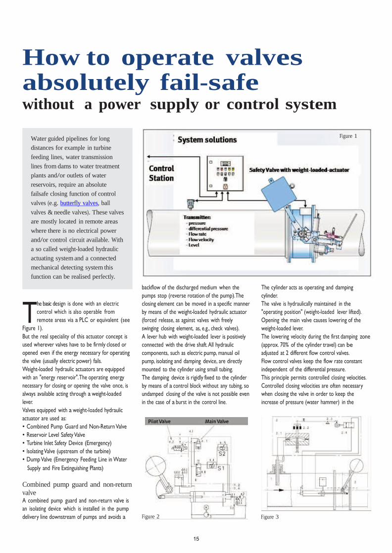
backflow of the discharged medium when the
pumps stop (reverse rotation of the pump).The
closing element can be moved in a specific manner
by means of the weight-loaded hydraulic actuator
(forced release, as against valves with freely
swinging closing element, as, e.g., check valves).
A lever hub with weight-loaded lever is positively
connected with the drive shaft. All hydraulic
components, such as electric pump, manual oil
pump, isolating and damping device, are directly
mounted to the cylinder using small tubing.
The damping device is rigidly fixed to the cylinder
by means of a control block without any tubing, so
undamped closing of the valve is not possible even
in the case of a burst in the control line.
Figure 1 The cylinder acts as operating and damping
cylinder.
The valve is hydraulically maintained in the
"operating position" (weight-loaded lever lifted).
Opening the main valve causes lowering of the
weight-loaded lever.
The lowering velocity during the first damping zone
(approx. 70% of the cylinder travel) can be
adjusted at 2 different flow control valves.
Flow control valves keep the flow rate constant
independent of the differential pressure.
This principle permits controlled closing velocities.
Controlled closing velocities are often necessary
when closing the valve in order to keep the
increase of pressure (water hammer) in the
Combined pump guard and non-return valve A combined pump guard and non-return valve is
an isolating device which is installed in the pump
delivery line downstream of pumps and avoids a
Figure 2 Figure 3
15

2 June 2009
THE MANUFACTURER’S VOICE
Figure 4 Figure 5
pipeline within an admissible range for closing times
as short as possible (see Figure 2).
For compensating the difference in flow rate
between the cylinder chamber on the rod side and
on the piston side and for receiving a small oil
reserve for losses due to leakage the actuator is
equipped with a compensating tank with oil level
sight control.
Mechanical solution with differential
pressure transmitter (Figure 3) At pitostatic tubes, probes, venturi nozzles and
standardized nozzles, flow produces a differential
pressure which can be received at the bores for
pressure measuring of the units.
The differential pressure is proportional to the flow
velocity in the pipeline. This differential pressure is
evaluated in a control device. In case of over-
velocity the control device transmits a mechanical
hydraulic
signal to the pilot valves of the weight-loaded
hydraulic actuator.
Switching over of the pilot valves causes lowering
of the weight-loaded lever and closing of the.
Closing is effected with graded velocity. During the
1st step, the valve is to close as quick as possible in
order to minimize the outflow rate. During the 2nd
step of the travel till CLOSED position), the valve is
closed slowly for avoiding water hammer in the
pipeline.
Mechanical solution with Paddle Trip
Mechanism (Figure 4) Flow produces an impact pressure on the bowl.
This leads to a movement of the paddle trip lever.
This rotation is transmitted through the paddle trip
body to the outside where a weight-loaded lever
runs on a cam disc. After a certain movement of
the paddle trip lever the weight-loaded lever of the
paddle trip mechanism drops from the cam disc.
The rotation of the weight-loaded lever of the
paddle trip mechanism opens a ball valve which is
installed as a pilot valve in the hydraulic circuit of
the weight-loaded hydraulic-actuator. Opening of
the pilot valve causes the valve / actuator to close.
Summary Weight-loaded hydraulic actuators are mounted to
valves which have to perform with high security.
By means of the lifted weight-loaded lever the
operating energy for a single valve movement is
provided for secure action at all times.
Controlled closing velocities allow quick
decrease of the flow in the pipeline so during a
2nd step soft isolating of the pipeline is
guaranteed. Pressure increase in the pipeline can
therefore be safely limited.
Construction using small tubing as well as the use of
control blocks rigidly fixed on the cylinder offer the
security that the closing process of the valve is
damped even in case of a burst in the control line.
The introduced design of the weight-loaded
hydraulic actuator offers various advantages as a
tubeless assembly to avoid damage of fluid-lines
resulting in malfunction, full functionality without
power supply and control connection – therefore
highly fail-safe – allows installations in remote areas
as it can be commissioned and ready to work with
manual pre-setting only.
Can be attached to any valve that requires a part-
turn-action of 90° maximum which is usually a
butterfly, ball or needle valve (Larner Johnson /
Plunger Valves) – see Figure 5 – and works fully
independently. A reset after an emergency
shutdown can be done easily by means of a
manual hydraulic pump.
To avoid impermissible action of personnel all valves
and functions shall be secured by padlock. The last
picture shows assembly as a pump non return valve
(taking over the full function of a check valve) in a
cooling circuit of a refinery in Tubruq / Libya – see
Figure 6 – fully equipped with
additional sensors / limit switches for monitoring in
the control room.
Meet Günter Öxler
Günter Öxler has a long history within the valve industry. He graduated in
Process Engineering and Mechanical Engineering in Stuttgart, Germany,
holds a MBA degree in VWA as well as a Controlling degree and is a
REFA Specialist. For more than 25 years, Günter Öxler has worked for
several companies in the valve business, companies such as J.M.Voith GmbH
(Hydropower and Paper Machinery), Erhard GmbH (R+D Process Valves
and project engineering), and Festo AG & Co. KG (Project Manager and
Project Engineer Process Automation). He is also member of the
IWA, ISA, and VDI German Engineer and he is multilingual as he speaks 5
languages, among which are German, English, French, Italian and Spanish.
Günter can be contacted under: [email protected]
Figure 6
16

September 2009 1
T
THE MANUFACTURER‟S VOICE
Manual operation and manual override – are they really necessary?
Why are engineers asking for
manual operation on drive
systems and what is the
reason for having a manual
override on automated process
valves?
Since process valves are
subject to automation, during
tending, most planning
engineers, operators and
consultants frequently require
a manual override on those
automated process valves. Is it
just an unwillingness to believe
in the technical reliability of
automation and actuating
systems or is there really a
reason to have this option
available?
o find an answer for this
question we look back at the
histor y of the process Industr y
and process automation.
Ever ybody has some concerns when we
talk about an automated system and its
reliability as we all have some knowledge
on power failure in our private lives –
just think about a lightning strike at night
while we are watching an interesting TV-
show. At the ver y least the power supply
to our TV set is cut-off and we have to
sit in candlelight. For most of us it‟s
normal but disturbing that we depend so
highly on those hidden utility supplies in a
black box. So in the case of automated
valves we feel much more comfor table
when there is a possibility available to
have an access to the system where we
can interact “manually” in case of any
failure.
The 20th centur y saw the introduction of
much automation in industrial facilities.
Within the process industries it star ted
mainly after the 2nd World War – with
Electricity!
The first automation of process valves
began with electric actuators. At that
time the reliability of those systems was,
let´s face it, on a low level and the
networks were slightly unstable, so it was
common for the power supply to be
interrupted. To guarantee a control
possibility, even if only a stop / closing or
opening function, it is absolutely
necessar y to have a manual override
available to put the process valve in a fail-
safe position. There is a good chance this
will not be the case if those valves /
actuator are not installed in a safety
circuit where a proper and fast action,
depending on the process parameters, is
required (please see the ar ticle in Valve
Figure 1: Electric actuated process valve
World June 2009: How to operate valves
absolutely fail-safe – without a power
supply or control system).
On the other side the electric actuators
need a manual hand-wheel/override
during adjustment of the process valve
and during commissioning and star t-up of
the process since there is usually no
power available during this condition
and/or for safety reasons (see figure 1 –
electric actuated process valve)
One ver y specialised solution for
ensuring a fail-safe power supply would
be a power pack with batteries on a DC
motor – but that is ver y, ver y expensive
and needs extensive maintenance.
With the progression and boom in
automation in the process industr y
another option for drive systems to
process valves came up –the pneumatic
Figure 2: Pneumatic operated process valve
17

2 September 2009
THE MANUFACTURER‟S VOICE
air-operated system. Definitely it was not
a new technology (we have seen
pneumatic drives for as long as electric
operated systems have been around) but
the „80s of the last centur y saw the latest
improvement influenced by factor y
automation systems – proper and long
lasting compressor devices, dr ying
systems to avoid freezing and corrosion
in the air supply system, absolutely
leakage free air tubing systems (leakage
costs a great deal of money) and finally
slip-stick free sealing systems for devices
such as cylinders and par t-turn actuators.
For the consulting engineers as well as
for the design engineers and operators it
was clear that a manual override – hand-
wheel – available, due to their decades of
experience with electric actuators as the
pneumatic drive system, was just another
way of actuating a process valve.
Mainly it has been and still is just a lack of
information about pneumatic air
automation!
If we look first at the industrial facilities of
the automotive industr y, food industr y
and so on, here nobody will think about
running all these pneumatic actuators
with a hand-wheel as they have never
used electric actuators before because
they were not able to fulfil the needs in
these locations of fast action, high
frequency, long lifetime, corrosion
resistance and, last but not least, fail-
safety! (see Figure 2 – pneumatic
operated process valve)
Wow – what a difference! All the
requirements we have in process
automation are available in factories
within the manufacturing industr y.
Pneumatic air has the advantage that
throughout the factor y (whether it´s
manufacturing or a processing plant) the
medium to run an actuator respective to
a process valve is available anywhere and
the production of the medium is done
somewhere outside the process – which
makes it highly reliable. Additionally no
Figure 3: Pneumatic circuit in process automation
air) and the wonderful thing about
compressed air is that it can be stored in
tanks.
This tank in a process area is the “batter y
pack”, if we compare it to an electrical
system, and feeds the process valve
actuating systems with the compressed
air guaranteeing a proper function along
the designed black-out-condition
coverage which is usually 1 to 2 hrs but
can be extended to several hours and is
just a question of the sizing of the tank.
The whole and complete SCADA
respective PLC systems run on a low
voltage 24V/DC system anyway which
can have a power back-up system of a
small batter y pack in the control room
(see Figure 3 – pneumatic circuit in
process automation)
Such a combination always guarantees
proper control of the system in the case
of power failure without using a single
manual override on a pneumatic actuator
- which is just wasting money and
increasing the need for maintenance of
those installations.
Meet Günter Öxler
Besides that, the installation,
commissioning & star t-up is done
manually with just a wrench for the end
position adjustment (usually done during
installation in the workshop as no torque
adjustment, running direction check is
required).
If the safety related standard requires an
absolute fail-safe function of OPEN,
CLOSE or HOLD it is common to use
spring-return actuators as they do not
even need pneumatic air to reach the
defined safety position!
Comparing a common installation of
electric actuators and a pneumatic
installation as shown in figure 3, the
pneumatic system shows a much higher
availability than an electrically operated
system, even if we do not find any
manual override on the actuator itself.
In the next issue we will focus on the
influence of pneumatics on safety as well
as SiL (Safety integrity Level issues) to
IEC 61511.
high voltage is necessar y inside the
processing area, only an air-pipe network
which is frequently of plastics (if
necessar y steel, stainless steel) plus a low
voltage signal wiring for SCADA systems
and monitoring.
The compressed air is usually supplied
with a pressure between 7 – 8.5 bar and
is produced with redundant compressor
systems (maintenance free as it is oil-free
Günter Öxler has a long histor y within the valve industr y. He
graduated in Process Engineering and Mechanical Engineering
in Stuttgar t, Germany, holds a MBA degree in VWA as well
as a controlling degree and is a REFA specialist. For more
than 25 years, Günter has worked for several companies in
the valve business. He is also a member of the IWA, ISA and
VDI German Engineer.
Günter can be contacted under [email protected]
18

Th e Ma n u fac T u r e r ’ s Vo i c e
Saving costs:pneumatic actuation in water and wastewater technology
This article compares the costs of automation of a Water Treatment Plant between pneumatic and electric Actuator technology for process valves based on quality equipment in process valve manufacturing. It is based on a realistic and near-application example and shows the enormous cost advantage of using pneumatic actuators and automation technology. The comparison is not only based on a direct comparison between electrical actuators versus pneumatic actuators, but includes all equipment and technical infrastructure necessary for automation with one or other actuation technology. This procedure mirrors the way of thinking of a company who is producing both actuators and the complete range of valves as well: only a complete overview of a (automation) project allows the finding of a cost effective and customer-specific system-solution. An important part of this is the completeness of the delivery-program for one or other technology (pneumatic or electrical).The final chapter “Pneumatic energy supply“ gives a brief overview of the most important questions regarding the compressed air supply and compressed air costs.
1. Suppositions for the sample calculationThe basis of the cost comparison is a water treatment plant with 8 fixed bed filters. This example can be projected to many applications in the industrial
and municipal water and wastewater treatment.Characteristics of the Water Treatment Plant:• 8 fixed-bed filter ( e.g. sandfilter,
activated carbon filter)• 7 butterfly valves per filter tank, On-Off
characteristic• Space required by filter plant: 16 x 11m• Media In-line pressure 3 bar• Fully automatic, safe operation is
required
For every filter tank (i.e.: x 8) are installed:1. Raw water influent
Butterfly valve DN 125 2. Filtrate effluent
Butterfly valve DN 1253. Rinsing water feed
Butterfly valve DN 1504. Rinsing air feed
Butterfly valve DN 1005. Sludge water discharge
Butterfly valve DN 2506. (De-)Aeration
Butterfly valve DN 807. Pre-run discharge
Butterfly valve DN 80 Additional for the Whole plant (x2)
8. Raw water distribution Butterfly valve DN 250
The Butterfly Valves are automated either
with pneumatic single acting quarter turn actuators or with electrical actuators
Note:Single acting pneumatic actuators allow opening or closing of valves with an integrated spring pack. That means: even after a breakdown of the supply with electrical energy or compressed air a defined behaviour of the valve is realizable and this way high operational safety is given. When using electrical actuators, this function is only possible when a battery buffered power supply is installed (Costs!).The pneumatic actuators are calculated for a differential pressure of 8.4 bar to make sure that the valves open or close under all possible operating conditions. But the standard and calculated base is a pneumatic pressure of 5.6 bars whereas the supply pressure of the compressor is 8.4 bar. The difference is used as compensational pressure to guarantee several cycles of any specific actuator to run under break-down and / or shut-down conditions of the pneumatic compressor.A defined movement of valves with pneumatic actuators can also be realized with double acting quarter turn actuators, when a single stable solenoid valve and a compressed air reserve tank is used.
19

Th e Ma n u fac T u r e r ’ s Vo i c e
Interpretation of the suppositional prices:• The prices are average market prices of
actuators for contractors• All prices defined without valve – easy
to compare• Prices of the electrical actuator include
the motor-control and cabinet part • A correct comparison of same functions
of electrical installation is only possible this way
• All prices in Euro per piece, based on prices in Germany.
• Total calculation is proven by international contractors and is confirmed
Control of the actuators:• Control with PLC• For controlling the pneumatic actuators
– any state-of-the art valve terminals (or single solenoid valves on a sub-base) are provided e.g. Camozzi, and so on:
1. 4 x cabinet each with 14 x 3/2 monostable Solenoid-valves and each terminal for 2 filters
2. 1 x cabinet with 4 x 3/2 monostable Solenoid-valves
Both alternatives (see below) can be offered with either multi pin (parallel I/O) or Field-Bus-Interface. The valve terminals are completely mounted and inspected, including accessories. Calculated accessories are: Maintenance unit, Fittings, Noise Reducer, Cable and Connectors.
We calculate 2 possible basic installations:1. Conventional wiring by using the parallel
I/O-level (Multi-Pin)2. Up to date solution with Fieldbus
(Profibus, Interbus-S, ...)
Interim Result :The resulting difference is 30591.-€ to the benefit of pneumatic, including higher operational safety by using spring packs in the actuators. Double acting actuators are more economically priced. It is important to be aware of the high robustness, the added explosion-proof abilities and the service and maintenance-free construction of pneumatic actuators. Additionally pneumatic actuators are overload-safe, provide continuous load operation and are designed for 100% operation time. Operation modes like S2, S3 etc and over-
Valve Size P-Actuator P-Accessories * E-ActuatorRaw water DN 125 236 65 894Filtrate DN 125 236 65 894Rinsing water DN 150 372 65 929Rinsing air DN 100 212 65 885Sludge water DN 250 757 65 1078(De-) Aeration DN 80 211 65 885Pre run DN 80 211 65 885Subtotal 2235 455 6450Total for each filter 2690 6450Total for 8 filters in the plant 21520 51600 Raw water distribution (x2) DN 250 757 1078 DN 250 757 1078Subtotal 1515 2156Total 1645 2156 Costs of actuators for complete plant 23165 53756
* P-Accessories = End position switches, Fittings etc.
temperature are not applicable in the case of pneumatic actuators.Additionally, a very important fact to be considered is that all pneumatic actuators come as oil-free actuators. The reason is:• Lubrication inside the air system creates
a slip stick effect inside the actuators in the long term, which causes a step-wise actuation and prevents smooth non-stop running of the actuators. With oiled air control of the actuators is difficult – in the long run impossible.
• Needs constant lubricated air maintenance of the used components including compressors , actuators and solenoid valves.
• Result / requirement: maintenance-free means NON-LUBRICATED air and oil-free compressor systems.
2. Cost estimation2.1 Original costs of the actuators
2.2 Costs for Controlling and Installation by using Parallel I/O-level-wiringListed are the costs for controlling with PLC, installation and mounting of the actuators. The calculated length of cables and tubes result from the supposed size of the filter plant. Fur ther we have supposed, that the cabinets are installed near the filter tanks. Costs for
the cabinet itself are not calculated, only necessary equipment to control the actuators.
Interim Result:The resulting difference is 36116.-€ to the benefit of Pneumatic. This cost advantage is mainly based on the lower quantity of I/O ‚s for controlling the pneumatic actuators with the PLC.Lower quantity of I/O’s means additional reduction of Engineering, Programming and Documentation effor ts. As a result of this, the effor ts to configure the PLC by using pneumatic actuators is lower because less I/O’s have to be designed and configured.Additional advantage for the operator :Less complex plant and plant control and therefore less possibilities to create mistakes/ failure. When designing big plants, fewer I/O’s have more effect on the costs of the PLC and peripheral equipment.
2.3 Costs for Controlling and Installation with FieldbusInterim Result :The automation concept with Fieldbus again shows that pneumatic installation has big advantages compared with electrical installation: the cost advantage
20

Th e Ma n u fac T u r e r ’ s Vo i c e
What is installed Costs per Piece P-Actuators E-ActuatorsActuators -- 23165 53756Valve terminal complete, incl. multi-pin-connector and cable, maintenance unit -- 7200 --PLC installation each with 32 I/O channels1 500 3000 95003-Row cage clamp connector incl. installation 2 360P-Actuators 180 Pcs. 2 1260E-Actuators 580 Pcs.I/O cable in cabinetP-Actuators 6 Pcs. 80 480E-Actuators 19 Pcs. 80 1520Installation time PLC I/O in terminals2
P-Actuators 180 hrs. 35/hr 630E-Actuators 580 hrs. 35/hr 2030Pneumatic ring-pipe 13mm , appr. 80m 5/m 400 --T-Distributor 4 Piece 12.5 50 --P-Subdistributor 8mm , appr. 50m 1/m 50 --Connections P-Actuators 8mm , appr. 120m 1/m 120 --P-Instant-connectors, QuickStar 120 piece 1.50 180 --Plastic-cable tunnel/platform appr. 70m 10/m 700 700Installation time Connector with Limit switch3 35/Hour 210 --Motorcable 5x1,5 appr. 200m 1.5 -- 300Controlcable 15 x 0,75 appr. 200m 3.5 -- 700Motorterminal (58 E-Actuators x 5 terminals ) 2.5 -- 725Incl. Installation, total 290 connections Connect control cables to E-Actuator4 35/hr -- 420Connect Motorcables to E-Actuator5 35/hr -- 350Test I/O cables/tubing (pneum) start up6 50/hr 1200 2600Total 37745 73861
1 P-Actuators : per actuator 2 PLC In (end position) and 1 PLC Out (valve), resulting in 58 actuators = 174 PLC I/O’s. No monitoring signals necessary as pneumatic actuators are overload safe and designed for 100% power-on-time.E-Actuators : Wiring to PLC includes torque, over-temperature and end-position monitoring Resulting I/O’s approx. 10 per Actuator, for 58 Actuators = 580 PLC I/O’s 2 I/O channel x 3 cores x 2 terminalsides x 1 min.P-Actuators 180 channels = 1080min. = 18 hoursE-Actuators 580 channels = 3480min. = 58 hours3 58 P-Actuators x 2 connectors x 3 poles = 180 cores x 1 min. 348min. = 6 hours4 58 E-Actuators x 12 cores x 1 min. = 700min. = 12 hours5 58 E-Actuators x 5 poles x 2 sides (motor + cabinet) = 580 min. = 10 hours6 P-Actuators 174 I/O’s appr. 3 days = 24 hours E-Actuators 580 I/O’s appr. 9 days = 72 hours
is more than twice the advantage of conventional installation.Using Fieldbus reduces the costs for both actuator technologies regarding installation and wiring, improves the monitoring of the system and has a big time advantage in installation when upgrading or modernizing the plant and when optimizing or improving the process. 2.4 Summarising the costsResult:The cost-advantage of the pneumatic solution is factor 1,9 and 2,5 higher than the electric solution.Double acting actuators, instead of using single acting actuators, increase this cost advantage.Comparison Parallel-wiring to Fieldbus:The Fieldbus technique for pneumatic installation has a cost advantage of appr.10 %. This relatively low cost advantage is shown from the comparison between multi-pin-connected valve terminals and Fieldbus connected valve terminals. Please note, the Valve terminals themselves already have a high integration rate. If a single solenoid valve solution were compared with the Fieldbus installation, the cost advantage for Fieldbus would be much higher. The comparison with parallel wiring to Fieldbus installation in the case of electric actuators shows only a small advantage for the Fieldbus system. This is the result of the characteristic of installations with electric actuators, every actuator is a single Fieldbus par ticipant (compare: a valve terminal for up to 26 valves is one par ticipant only).
Additionally pneumatic has the following main advantages:- Small requirement of space- Smaller volume of cabinets- Less complex, “simple“ and robust
technology- Overload-safe and 100% operating time- Higher operational safety by using air as
second energy-supply - Fewer spare parts required- Lower engineering-and programming
costs- Lower maintenance costs- Transparent, easy to manage process
21

Th e Ma n u fac T u r e r ’ s Vo i c e
Kind of installation Single costs P-Actuators E-ActuatorsActuators -- 23165 53756Valve terminals with Fieldbus incl. all connectors and maintenance unit for 7922P-Actuators 27550Fieldbus interface for E-Actuators incl. 475internal x 58 piece PLC Fieldbus-Masterconnection1
P-Actuators 5 participant 900 900E-Actuators 58 participant 1800Fieldbus cable, Copper-cable P-Actuators 50m 2 100E-Actuators 300m 2 600Fieldbus connection valve terminals2 35/hr 35 --Fieldbus connection E-Actuators3 35/hr -- 350Pneumatic ring-pipe 13mm , appr. 80m 10/m 400 --T-Distributor 4 Pieces 12.50 50 --P-Sub-distributor 8mm , appr. 50m 1/m 50 --Connections P-Actuators 8mm, appr. 120m 1/m 120 --P-Quick connectors, QuickStar 120 piece 1.5 180 --Plastic cable tunnel/platform appr. 70m 7/m 490 490Installation time limit switch connector 35/hr 210 --Motorcable 5 x 1,5 appr. 200m 1.50 -- 300Motorterminals (58 E-Actuators each with 5 terminals ) incl. installation 2.5 -- 725Connection Motorcables to E-Actuator 35/hr -- 350Test I/O Cables/Tubing (pneum) Start up4 50/hr 400 1200Total 34022 87121
2.5 Original Costs of Controllable ActuatorsThe valves and actuators in our example work in ON-Off-characteristic. But besides this, applications for controlled actuators (analogous characteristic) are very common. In water treatment plants, industrial wastewater treatment plants and especially in the chemical industry, controlled valves with pneumatic quarter turn actuators are very often used. In our example, the filtrate effluent could be controlled. For controlling a valve, the quar ter turn actuator is equipped with a positioner. Example: Butterfly valve DN 125. Comparison between electric and pneumatic solution:
3. Pneumatic Energy-supplyPneumatic actuators are driven with compressed air and compressed air does not come free. In fact the quality of the compressed air is nearly as important as the quality of an electrical power supply for the long-term maintenance-free working of actuators.The preparation of compressed air should contain:• Compressor with filter• Tank for compressed air• Dryer• Maintenance unit • Installation should have somewhere to drain the condensate.
Dimensioning - how?The following tips are to give direction, to get a feeling for the dimensioning of a compressed air supply.Compressor : The basis for choosing a compressor is the required pressure and air volume of the installation.Finding the effective output of a compressor :1. Specify the maximum consumption
of all compressed air consumers per time unit
(worst case specification, how many actuators at the same time?).
2. Estimate the additional required compressed air consumption for the next 10 years.
3. Calculate leakage (10% for new plants).
Summarizing 1 to 3 is the total
1 Calculation based on Fieldbus Profibus DP, each 32 parts per segment, RS 485, 1,5 Mbaud. The small number of parts involved in pneumatic is the result of using valve terminals, which, in our example, can control up to 26 actuators (14 used in this example).2 Connection to 4 valve terminals each with 2 connectors and 1 valve terminal with 1 connector and 1 connector to PLC Master.10 Connector x 5 min.= 1 hour3 Fieldbus connection to 54 E-Actuators each with 2 connectors + 2 x 1 for the last actuator + 2 for each PLC mastercard = 112 connectors x 5 min. = 560min. = 10 hours4 Configuration of the Fieldbuses, addressing the pieces etc.P-Actuators = 8 hours ( 5 pieces )E-Actuators = 24 hours ( 58 pieces )
22

Th e Ma n u fac T u r e r ’ s Vo i c e
Valve DN Air consumption standardized litre ( NI ) at 6 barRaw-water supply 125 4Filtrate effluent 125 4Rinsing water supply 150 8Rinsing air supply 100 4Sludge water drain 250 15(De-)aeration 80 3Pre-run 80 3Total per filter 41x 8 filter 328 Raw water distribution 250 15 250 15Total raw water distribution 30 Total consumption (all actuators operating at the same time) 358 NISupposition: all valves open once a day, including leakage appr. 800 NI / dayConsumption/minute 0.6 NI / min.
Type of installation Total Pneumatic Total Electric DifferenceParallel wiring using I/O - level 37745 73861 36116Controlling with Fieldbus 34022 87121 53099
Installation P-Actuator E-ActuatorActuator for butterfly valve DN 125 236 1302 1Electro-pneumatic positioner incl. end position feed back, end position switches4- 20 mA I/O 1000Total 1236 1302
Example: Air consumption of a water treatment plant:
1 Controllable E-Actuator incl. gear
requirement of compressed air.For requirements up to 100 m³/h the operating time of the compressor should be a maximum of 50%, the effective air supply is then twice the sum you have found above.Compressed air storage tank: To guarantee a constant pressure in the compressed air supply system as far as possible, a storage (buffer) tank is used. Compressors are often offered with integrated tank.Criteria for the size of a storage tank:• Capacity of the compressor • Air requirement for the complete
installation (including piping)• Maximum allowed pressure difference
in the air supply installation• Safety in case of energy breakdown.
Finding the size of a compressed air buffer tank:Example: The tank to ensure the full supply of our sample-plant for at least 12 hours.Maximum allowed pressure drop: max. from 7 until 6 bar (=∆ p 1 bar).Compressed air requirement / 12 h: 400 lRequired Air-Volume = ∆ p * vwith: ∆ p = differential pressure in barv = volume of storage tank in l Result : 400 l
Costs of producing compressed air :Original costsOperating time of the compressor : 800l/d / 13 l/min. = 62 min/d, appr. 1,5 h/d.
Power supply costs: 0,27 kW x 1,5 h/day x 365 days/a x 0,10 Eur/KWh = appr. 15 Eur/year
Why is a bigger compressor often used?Often additional air is needed, for example to rinse the fixed bed filter with air, to work with a filter press in wastewater systems. But very often the reason is a high uncer tainty in dimensioning the system.
4. ConclusionWe have shown an intelligent pneumatic system for automation of a water treatment plant and the high cost advantage of pneumatic compared to electrical installations. But why is the electrical installation often preferred? It’s important always to look at the whole system. In a tender today it’s usual to divide the electrical par t, the cabinet par t and the single valve-actuator par t. Working this way, the total costs of an electrical system can’t be seen. Pneumatic systems are often seen as a unit and that way seem to be more expensive.
23

April 2010 1
T
T h e M a n u f a c T u r e r ’ s V o i c e
Simplify Your Process Control Solution Example given for a valve control solution in a batching system for printer ink!
This write-up will give you an
idea of where specialized
knowledge and top quality
material is required to fulfill
specific needs in the process
industry. It is not the job of a
process engineer to get the job
done by using more-and-more
electric control equipment - NO
- it is his / our responsibility to
keep it as simple as possible
which makes the system highly
resistant against malfunction
Figure 2 Figure 3
and defects - and absolutely
cost-effective.
As an example to show what
this means I am using a printer
ink mixing & batching machine.
Machines for production –
batch production - of printer ink
are specially designed as they
need very reliable components
with an extraordinary lifetime
and perfect quality. A machine
is only as good as the weakest
component in it (see figure-1).
Figure 1
he parameters out of the
production / batching process
of the ink are not really sensitive
as we mainly talk about ambient
temperature around +20° to + 40°C .
The cycle time is around 1 x / 5
minutes!
Chemical resistance is the major point:
• The standard ink compounds are
not seriously aggressive and basic
elastomere will work.
• It is the cheapest solution - EPDM! (of
course FKM / Viton will do as well, but
increases the costs)
• Problem: only the solvent which gives
the ink the right consistency. For most
of the solvents as well EPDM is the
right choice
Attention: We have to take ver y special care of the
circumstance that the described herein
coaxial valves are fitted with EPDM
Seals - which means these seals are not
able to work with most of the common
lubricants and use with the ink media
also does not allow the use of Silicon
as a lubricant. In maintenance work and
/ or exchange of the sealing sets great
care has to be taken with the issue that
no lubrication is used, otherwise the
seals will expand under the influence of
the lubricant and the coaxial valve will
become stuck within a ver y shor t time
and the seals will be damaged fur ther as
the valve is no longer moving!
In these ink batching machines we find
quite a number of valves:
1. 3-piece stainless steel ball valves –
sizes ranging from 1” up to 2”
2. Ball Valves – 2-piece body with female
thread connection made of brass
from 1/2” up to 2”
3. Coaxial-Valves ranging from ½” up to
2” with EPDM Seals.
4. NAMUR solenoid Valves
Figure 2 shows the installation - inflow - to
one of the various batching stations.
Figure 3 shows a coaxial valve for fast -
ON / OFF action, responsible for opening
and / or closing the media flow. Above
each coaxial valve we can see a standard
24

2 April 2010
T h e M a n u f a c T u r e r ’ s V o i c e
3-piece stainless steel ball valve and, as a
specialty, these ball valves are equipped
with a manual lever in a different position
- and no positioner or process controller
is installed!
The reason for the different positions is
that the batching of the ink requires
almost 10 different media with all having
a different density as well as a different
percentage in the finished batch, so
it is necessary to adjust the inflowing
quantity to the appropriate volume.
During the commissioning and star t-up
of the machiner y all these valves are set
according to the individual requirements
and process parameters of each batching
machine.
Of course this can also be done with
sophisticated process controllers but
this will increase the costs as well as the
Solving these requirements by using an
electronic control system will lead to
many more failure possibilities, at the same
time influencing the possible reachable SiL
- Level. The question of what SiL has to
do with an ink batching machine is a good
one, and the answer is as for the process
itself: use simple, understandable and non-
complex examples to explain an issue.
With the example of the ink batching
machine we can easily understand the
problem we have to solve and the
background. After a proper understanding
of the easier problem we are able to apply
it the same way to much more complex
problems - which is real & practical
Meet Günter Öxler
process engineering.
One more time: keep it as simple as
possible but efficient.
Figure 4
complexity of the control system and
results in a tremendous increase to the
investment in:
• Hardware
• I/O s in the PLC system
• Programming the Software
• And, last but not least, increasing the
maintenance work, stock holding &
much more.
Günter Öxler is a freelancer to the Process Industry and has a long
histor y within the valve industr y. He graduated in Process
Engineering and Mechanical Engineering in Stuttgar t, Germany,
holds a MBA degree in VWA as well as a controlling degree and is
a REFA specialist. For more than 25 years, Günter has worked for
several companies in the valve business. He is also a member of
the IWA, ISA and VDI German Engineer.
Günter can be contacted under [email protected]
25